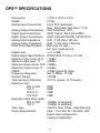
1
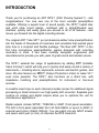
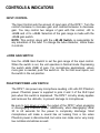
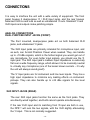
The ART DPS DI/O Preamp System TABLE OF CONTENTS Introduction ........................................................................................... 2 Installation ............................................................................................. 4 AC Power Hookup .............................................................................. 4 Analog Audio Connections .................................................................. 4 Safety Precautions .............................................................................. 4 Controls and Indicators .........................................................................5 Input Control ....................................................................................... 5 +20 dB Gain Switch ............................................................................ 5 Phantom Power +48V Switch ............................................................. 5 Phase Reverse Switch ........................................................................ 6 V3 Variable Valve Voicing Control ................................................... 6 VU Meter ............................................................................................. 7 Output Control .................................................................................... 7 Connections ........................................................................................ 10 Dual Purpose Input Jacks (Front) ...................................................... 10 XLR Input Jacks (Rear)...................................................................... 10 XLR Output Jacks (Rear) .................................................................. 11 ¼” Output Jacks (Rear)...................................................................... 11 Operation ............................................................................................. 14 Warranty Information .......................................................................... 16 Service ................................................................................................. 17 DPS Specifications .......................................................................... 19 -1- INTRODUCTION Thank you for purchasing an ART DPS (DI/O Preamp System) - and congratulations: You now own one of the most versatile preamplifiers available. Offering a superb level of sound quality, the DPS hybrid tube and solid state circuit design, combined with a straightforward user interface, quickly and easily gives you access to all of its features - and moves you forward into the digital recording domain. The original ART Tube MP put professional-caliber tube preamplification into the hands of thousands of musicians and recordists that wanted great tube tone in a compact and flexible package. The New ART DPS is the first tube microphone preamplification system designed with recording musicians in mind. It has been carefully designed, engineered and manufactured to provide you with years of great sound and reliable service. The DPS extends the range of applications by adding V3 (Variable Valve Voicing) which will help you to quickly and easily record a variety of instruments – including drums, keyboards, acoustic and electric guitars, and more. We also feature our OPL (Output Protection Limiter) to make V3 even more powerful. The DPS also functions as a direct box, with impedance matching and preamplification for instrument or line-level sources. A versatile insert loop on each channel provides access for additional signal processing or direct access to our high quality A/D converter. Separate gain controls on analog and digital outputs allow you to optimize the unit for simultaneous applications. Digital outputs include S/PDIF, TOSLINK or ADAT (front panel selectable). The A/D is front panel adjustable from 44.1kHz-96kHz or syncs to ADAT or external word clock (32kHz-100kHz). You can patch into any ADAT stream and select which pair (or ALL) of channels the DPS transmits. -2- The D/O Preamp System also features ART Analog to Digital conversion system and ART Tube Technology similar to that of the ART D/IO. This ensures that when you are going from the analog preamplification to digital, your signal will be as warm and musical as you decide it to be. The DPS does digital right! FEATURES: • Dual Analog VU metering • V3 (Variable Valve Voicing) with OPL (switch selectable) • Over 75 dB of gain • Hand selected 12AX7A dual triode tube • Balanced XLR inputs and outputs • ¼” High impedance Instrument input and ¼” line level output • +48V Phantom Power (switch selectable) • Phase Reverse Switch • Gain (+20dB) Switch • Input Gain Control • Output Level Control • ART A/D Conversion • Lower Noise At Low Gains • ADAT, S/PDIF, TOSLINK Digital Interfaces • 24-bit/96 kHz Operation • Fully shielded all-steel chassis • Designed and developed in the USA -3- INSTALLATION The DPS may be used in a wide variety of applications and environments. In a rack-mountable, all-steel enclosure, the unit is designed for continuous professional use. Mounting location is not critical. However, for greater reliability we recommend that you not place the units on top of power amps or other sources of heat. The tube circuitry needs about a minute to “warm up” from a cold power up. AC POWER HOOKUP The DPS has an internal power supply designed to operate at 115 VAC @ 50 to 60 Hz. Units manufactured for use outside the United States of America have been modified to comply with the required electrical specifications. ANALOG AUDIO CONNECTIONS Audio connections to and from the DPS are balanced XLR (Pin 2 = Hot (+), Pin 3 = Cold (-), Pin 1 = Ground) and unbalanced ¼” (Tip = Hot (+), Sleeve = Ground). We recommend that you switch off the +48V Phantom Power whenever changing connections to the XLR input. The front mounted jacks can act as both a balanced XLR connection, and an unbalanced ¼” connection. SAFETY PRECAUTIONS Warning: To avoid the risk of shock or fire, do not expose this unit to moisture. Refer all servicing to qualified personnel. Do not remove the metal cover; there are no user-serviceable parts inside. When applicable, only use the power adapter that came with this unit or one obtained from ART’s Customer Service Department. -4- CONTROLS & INDICATORS INPUT CONTROL The Input Control sets the amount of input gain of the DPS. Turn the control clockwise to increase gain and counterclockwise to decrease gain. You may control two ranges of gain with this control, +20 to +68dB and +0 to +48dB. Selection of the gain range is made with the +20dB gain switch. NOTE: This control, along with the +20 dB Switch, is responsible for any saturation of the tube. To change the tube character, utilize these 2 controls. +20DB GAIN SWITCH Use the +20dB Gain Switch to set the gain range of the input control. When the switch is out, the unit operates in Normal mode. Depressing the switch adds 20dB of gain. For microphone applications, where more gain is needed, push the switch in. For hot line level inputs, set the switch in the out position. PHANTOM POWER +48V SWITCH The DPS can power any microphone needing +48 volts DC Phantom power. Phantom power is supplied to pins 2 and 3 of the XLR Input jack when this switch is depressed. The DPS circuitry slowly applies and removes the +48volts, to prevent damage to microphones. Be sure to turn down or mute the output of the DPS when engaging or disengaging Phantom power. Additionally, when disengaging, allow 30 to 45 seconds for the power to completely discharge. Most microphones will make a sound like air leaking from a tire when Phantom power is disconnected, but some can make some very nasty low rumbles and whines as well. -5- Dynamic microphones should not be affected or damaged if they are plugged into a line where Phantom power is present. However, if the mic doesn't need it, do not use it. Some things are best left untested! PHASE REVERSE SWITCH The Phase Reverse switch is provided to reverse the phase of the signal. This switch works on Pins 2 and 3 of the XLR output jack and also reverses the polarity of the ¼” output jack. In the Normal position, the signal is in-phase. In the Reverse (or “in”) position, Pins 2 and 3 are reversed and the signal is changed to 180 degrees out of phase. In multiple microphone applications, mic placement can affect the phase of the signals. If two microphones pick up the same signal from different locations, the result can be a hollow or frequency “shifted” sound. In some cases it may sound as if an instrument disappears if it happens to be 180 degrees out of phase. Depressing the Phase switch can remedy this. In general, if your sound is “thin” or “out of position”, try reversing the phase to correct the problem. V3 – VARIABLE VALVE VOICING CONTROL The DPS features ART’s proprietary V3 technology. V3 (which stands for Variable Valve Voicing™), provides optimized reference points to begin the recording process for guitars, bass guitars, synths, acoustic instruments, percussion and more. ART engineers ran our preamplification circuit through a battery of tests and real life studio conditions. Our goal was to create a processor that would allow a user to have presets that were optimized for specific recording applications. We set out to create a preamp that would be nimble enough to handle both violins and kick drums, and everything in between. -6- We wanted to take the guessing out of the equation – and that is how we developed V3™. It’s simple, easy and it works really well. For example, if you are recording an acoustic guitar, V3™ has a preset that has been optimized for that instrument. Once the preset is chosen, the user can even fine tune the signal – which shows the true power of V3™ technology…it’s tweakable. V3™ even features a multi setting, which is useful for a wide variety of applications – like overhead micing, broadcast and field recording. This means that it is now quicker and easier than ever to make great recordings! Musicians want to play, not spend hours adjusting knobs. No other microphone preamp is as user-friendly as the DPS. VU METER The VU Meter gives an analog representation of the DPS tube signal level. Besides showing the average analog level, it is sensitive to attack transients. When not using OPL, the VU Meter is a great indicator of how hard you are running the tube. It also helps in setting a consistent level as you change mics and instrument sources. The VU Meter also reflects the impact of the OPL circuitry on the signal. For example, if the signal is “in the red” on the meter, the meter will reflect the attenuation of the signal when the OPL is activated, and the signal is brought out of the “red”. OUTPUT CONTROL The Output Control sets the output level of the DPS. When the control is fully counterclockwise, there is no output. Turning the control clockwise increases the level of the output signal. When setting the Output level control, refer to the VU Meter for an accurate level leaving the preamp. -7- DIGITAL LEVEL The digital level knobs control the input gain to the digital converters of the DPS™. The purpose of the digital level control is to get the loudest possible signal into the converters before clipping starts to occur. The front mounted clip lights easily notify the user before digital clipping occurs. For the optimal input signal, raise the gain until the digital clip lights just start to flicker, then back off on the digital level by a hair until the clip lights go out. One should most likely test this using the hottest signal they will be using (or use the OPL™ feature on the V3™ setting to get your levels just right.) There are several paths in which audio can reach the digital signal converters. One is the using the analog inputs of the DPS™. When used in said manner, the analog signals of both channels in the DPS™ automatically go into the digital converters. On the back of the DPS™ there is a side chain. One can either send out the signals to an effects processor, such as an ART Dual Levelar for additional compression, and return it to the DPS™ using the rear TRS jacks on the back. One could also patch directly into the returns off the side chain, and patch something directly to the A/D converters. SAMPLE RATE CONTROL This button controls the current sampling rate the DPS™ is working at. By cycling through the various settings, displayed by the upper LED row, one can use a variety of sampling rates. When the ADAT setting is used, the DPS™ syncs to incoming ADAT clock on the ADAT input. If the ADAT LED is blinking, the DPS™ has failed to find a valid ADAT clock. When the LED is solidly lit, it has found an acceptable ADAT clock signal. When EXT is selected, the DPS™ looks to the Word Clock input and synchronizes itself to that. If no word clock signal is present, the LED will blink informing you of that no valid word clock signal is present. -8- Typically, the higher the sample rate, the more accurate the digital conversion is - but frequently, one is limited by the digital recording system being used. Make sure that, when selecting your sampling rate, the digital recording system you are working with is operating at the same rate. ADAT CHANNEL CONTROL This button controls the current ADAT channel the DPS™ is transmitting over. The DPS™ only transmits over ADAT when the sample rate is set to 48kHz (ADAT master clock mode), ADAT (ADAT Slave Clock mode), or EXT (Word Clock Sync mode). By toggling through, one can select to transmit over channels 1-2, 3-4, 5-6, 7-8, or all 8 of them at once. When no lights are on, this means all incoming ADAT channels are bypassed. This is frequently used when the DPS™ is in an ADAT chain, but not currently being used. -9- CONNECTIONS It is easy to interface the unit with a wide variety of equipment. The front panel houses 2 dual-purpose ¼” / XLR input jacks, and the rear houses balanced XLR ins and outs as well as unbalanced ¼” outs. Standard ¼” and XLR inputs and outputs make patching simple. ANALOG CONNECTIONS DUAL PURPOSE INPUT JACKS (FRONT) The front mounted, dual-purpose jacks act as both balanced XLR jacks, and unbalanced ¼” jacks. The XLR Input jacks are primarily intended for microphone input, and as such, can furnish Phantom Power when needed. They can handle up to +19 dBu signals, which is the hottest signal you would get out of any microphone. For even hotter input signals, you should use the ¼” input jack. The XLR Input jack’s medium input impedance is extremely flat over a wide frequency range, which allows it to be musically neutral to virtually any microphone (one of the lesser known secrets – it’s why the unit will always sound good!). The ¼” Input jacks are for instrument and line level inputs. They hav e high input impedance to minimize any loading effects on instrument pickups. They can also handle up to +22 dBu signals for line level signals. XLR INPUT JACKS (REAR) The rear XLR input jacks function the same as the front jacks. They are directly wired together, and both cannot operate simultaneously. If the rear XLR input and its matching front ¼” input are both in use, the DPS will sum the two signals, with the XLR slightly attenuating the ¼” input. This is not normally suggested. - 10 - XLR OUTPUT JACKS (REAR) The XLR Output jacks of the DPS are active balanced. You may use them in an unbalanced configuration without harm to the output circuitry. The XLR outputs can provide a hefty signal level (+28dBu) at a low impedance, so make sure that you do not overdrive equipment with sensitive inputs. When using the DPS™ on the front end of a mixer, go into the mixer’s line in or insert inputs and not necessarily into the mixer’s microphone input, unless the mixer can pad that input’s level. ¼” OU TPUT JACKS (REAR) The ¼” Output jacks are unbalanced and should be used for sending signals to amps, processors, or other unbalanced configurations. Both balanced and unbalanced output connections may be used simultaneously. This is particularly useful when using the DPS as a direct box for instruments or line level signals. Make sure that both pieces of equipment connected to the preamp’s outputs are connected to the same earth ground, beforehand, to avoid electrical shock. If you experience a grounding hum when using both output connectors (one to a console, one to an instrument amp) simultaneously, a ground loop may be the problem. To remedy this problem, disconnect the ground wire (pin 1) from the XLR cable plugged into the preamp’s output. This interrupts the ground path, and therefore breaks the loop. S/PDIF COAX OUT (REAR) The digital coax output jack on the DPS™ is an RCA type that outputs S/PDIF stereo signals over a coaxial shielded cable. The data format is S/PDIF stereo 24 bit data at up to 100kHz sampling rate. - 11 - Due to the wide bandwidth, A R T recommends the use of high quality, low loss, fully shielded cabling for the S/PDIF Coax connection. Note that the S/PDIF out must act as a master. On the digital system you are connecting the S/PDIF cable to make sure the device is set to sync to the incoming S/PDIF signal to ensure a high quality transmission. OPTICAL ADAT INPUT (REAR) The optical input of the DPS™ allows the user to use the DPS™ within an ADAT chain. The DPS™, when set to ADAT mode, synchronizes its sample rate with that of incoming ADAT clock signals. When in ADAT mode or EXT mode, the DPS™ can transmit on channels 1-2, 3-4, 5-6, 7-8, all channels, or merely act as an ADAT through. When the DPS™ is acting on 48 kHz sampling rate, it acts as an ADAT master, and it can only pass through ADAT channels if the source ADAT is in sync with the DPS™. OPTICAL ADAT OUTPUT/TOSLINK (REAR) The optical inputs are used for both TOSLINK and ADAT transmission. To transmit ADAT digital audio, the unit must be in 48 kHz, ADAT, or EXT mode. When in 48 kHz mode, the DPS™ acts as an ADAT master clock, when in ADAT mode the DPS™ syncs to incoming ADAT clock, and when in EXT, the DPS™ syncs to incoming Word Clock. In all 3 of these modes, one may set the ADAT transmission channels. When the output is set to S/PDIF, the DPS™ uses TOSLINK instead of ADAT transmission over the optical connection. WORD CLOCK INPUT (REAR) The BNC connection on the back of the DPS™ is used to synchronize the unit with an incoming Word Clock signal. To allow the DPS™ to sync up with the Word Clock input, set the Sample Rate to EXT. If no valid Word Clock signal is present, the EXT light will blink, notifying the user that it was unable to synchronize. - 12 - ¼” INSERTS (REAR) The DPS has 2 channel inserts that are routed just before the digital converters. The 2 female TRS jacks can be used to send the DPS’ analog signal to an external processing device, and then return the effected signal to the digital converters. The RING of the TRS is used to send the signal out, and the TIP is routed to the digital converters. One could also simply plug the output of a device directly into the insert jacks to directly go into the converters. - 13 - OPERATION The DPS is one of the most versatile preamplification systems available. Through use of the V3 technology, numerous instruments can be processed by the DPS. Simply mic the instrument (if acoustic), amp, speaker, or plug the instrument directly in to take full advantage of V3™ technology. V3 Settings and their applications when processing: When observing the V3 dial from a clockwise perspective, the following settings are: Neutral Settings: These are useful for uncolored, natural reproduction of sound. 6:00 - Neutral Flat 6:45 – Neutral Vocal (Microphone) 7:30 – Neutral Guitar Amplifier 8:15 – Neutral Bass Guitar Warm Settings: These are useful when warming a signal is desired. 9:00 – Warm Electronic Keyboard 9:45 – Warm Electric Guitar 10:30 – Warm Vocal Microphone 11:15 – Warm Valve Warm Settings with OPL: These are useful with high sound pressure levels, close proximity micing, and spiky transients, as well as warming the signal. 12:00 – Warm OPL Multiple Applications 12:45 – Warm OPL Vocal 1:30 – Warm OPL Acoustic Guitar 2:15 – Warm OPL Piano Neutral Settings with OPL: These are useful with high spl’s, close micing and spiky transients, as well as maintaining clarity. 3:00 – Neutral OPL Bass Guitar 3:45 – Neutral OPL Acoustic Guitar 4:30 – Neutral OPL Percussion 5:15 – Neutral OPL Limit - 14 - Using V3 : The V3 presets have been voiced with the intent of being a starting point for the recording process. The key to good recordings is to consider all the variables you will encounter during the process. For example…which microphone are you using? Are you recording a particularly bright guitar into a very trebly guitar amplifier? Are the strings on your acoustic made of metal or nylon? Is the room live or flat? We mention this because V3 is intended as a reference, not a hardand-fast absolute. For your particular applications, your bass guitar may sound better through a non-bass preset. If you need to, give it a twist…you’ll find the setting for the tone you are searching for! The DPS is ideal for use as a DI box. Plug the instrument into either input and use the XLR or ¼” (or both) outputs to connect to your recorder, board or PA system. Because of its low noise, excellent tonal qualities, and high quality digital converters, the DPS is ideal for running mixes through before recording to DAT, ADAT, DAW, or even into your computer. Used as a mastering device, the preamps are capable of adding warmth and gentle tube compression to the signal. Variable Input and Output level controls make the preamps in the DPS ideal for level matching material in postproduction situations…an extremely valuable use! - 15 - WARRANTY INFORMATION Limited Warranty Applied Research and Technology will provide warranty and service for this unit in accordance with the following warrants: Applied Research and Technology, (A R T) warrants to the original purchaser that this product and the components thereof will be free from defects in workmanship and materials for a period of three years from the date of purchase. Applied Research and Technology will, without charge, repair or replace, at its option, defective product or component parts upon prepaid delivery to the factory service department or authorized service center, accompanied by proof of purchase date in the form of a valid sales receipt. Exclusions: This warranty does not apply in the event of misuse or abuse of the product or as a result of unauthorized alterations or repairs. This warranty is void if the serial number is altered, defaced, or removed. A R T reserves the right to make changes in design or make additions to or improvements upon this product without any obligation to install the same on products previously manufactured. A R T shall not be liable for any consequential damages, including without limitation damages resulting from loss of use. Some states do not allow limitations of incidental or consequential damages, so the above limitation or exclusion may not apply to you. This warranty gives you specific rights and you may have other rights, which vary, from state to state. For units purchased outside the United States, an authorized distributor of Applied Research and Technology will provide service. - 16 - SERVICE The following information is provided in the unlikely event that your unit requires service. 1) Be sure that the unit is the cause of the problem. Check to make sure the unit has the proper power supplied, all cables are connected correctly, and the cables themselves are in working condition. 2) If you find the unit to be at fault, write down a complete description of the problem, including how and when the problem occurs. Please write down a description of your complete setup before calling Customer Service. 3) Contact our Customer Service Department at (585) 436-2720 for your Return Authorization number or questions regarding technical assistance or repairs. Customer Service hours are 9:00 AM to 5:30 PM Eastern Time, Monday through Friday. 4) Pack the unit in its original carton or a reasonable substitute. The packing box is not recommended as a shipping carton. Put the packaged unit in another box for shipping. Print the RA number clearly on the outside of the shipping box. Print your return shipping address on the outside of the box. 5) Include with your unit: a return shipping address (we cannot ship to a P.O. Box), a copy of your purchase receipt, a daytime phone number, and a description of the problem. 6) Ship your unit (keep your manual!) to: APPLIED RESEARCH AND TECHNOLOGY 215 TREMONT STREET ROCHESTER, NEW YORK 14608 RA# ____________________ - 17 - Fill in the following information for your reference: Date of purchase ___________________ Purchased from ___________________ Serial number ___________________ - 18 - DPS SPECIFICATIONS Dimensions Weight Analog Input Connections 1.75”H x 19”W x 6.5”D 5.5 lbs. Front: XLR (balanced) Rear: Switchable XLR (bal.)/ ¼” TS, Analog Output Connections XLR (balanced), ¼”TS, Digital Input Connections ADAT Optical, Word Clock BNC Digital Output Connections ADAT Optical/TOSLINK, S/PDIF RCA Analog Input Impedance XLR, ¼” 5K ohms,1M ohm Analog Output Impedance XLR, ¼” 300 ohms,150ohms Word Clock Specifications BNC jack, 5V max., Ext. sync mode source Digital Level -∞ to +10dB Digital Output Specifications S/PDIF RCA 75 ohms, 0.5 Volt Maximum Input Level, XLR +19dBu Maximum Input Level, ¼” +22dBu Maximum Output Level, XLR +28dBu Maximum Output Level, ¼” +22dBu CMRR >75dB (typical @ 1kHz) Frequency Response 5Hz to 50kHz, +/-.1dB Dynamic Range >100dB Total Harmonic Distortion <0.01% (clean), <0.1%(warm) Maximum Gain XLR to XLR 80dB ¼” to ¼” 68dB XLR to ¼” 74dB ¼” to XLR 74dB Equivalent Input Noise (EIN) XLR to XLR -129dBu (A weighted) ¼” to ¼” -105dBu (A weighted) Tube Type 12AX7A, Dual Triode, Hand Selected Power Requirements USA – 110-125V AC / 50-60hz/ 16W Export units configured for country of destination. - 19 - ART maintains a policy of constant product improvement. ART reserves the right to make changes in design or make additions to or improvements upon this product without any obligation to install same on products previously manufactured. Therefore, specifications are subject to change without notice. Applied Research & Technology 215 Tremont Street Rochester, NY 14608 USA (585) 436-2720 (585) 436-3942 (FAX) www.artproaudio.com © 2002 Applied Research & Technology - 20 -