1
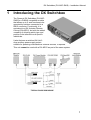
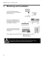
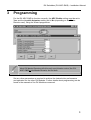
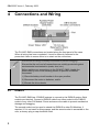
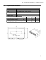
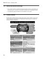
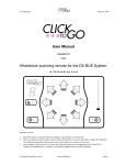
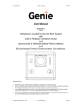
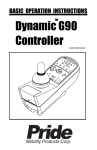
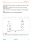
DX Switchbox (DX-ARC-SWB)
Installation Manual
by
GBK62297 Issue 1, February 2003
GBK62297 Issue 1, February 2003
About this Manual
This manual has been designed to help you install and configure a Dynamic DX Switchbox
(DX-ARC-SWB) module for a ‘generic’ brand powerchair. For this reason there are no
guidelines for specific applications, and this should be read in conjunction with the Installation
Manuals for all other DX Modules present in the system.
If there is a specific requirement for your application, please contact Dynamic Controls or one
of the sales and service agents, as we can assist you to configure the DX-ARC-SWB for this
application.
Throughout this manual there are a few symbols that will help you quickly identify the purpose
of the paragraph that follows:
Notes:
Notes provide supporting information for the previous paragraph or
section that should be followed in order to install, configure, and use the
DX-ARC-SWB safely and efficiently.
Warnings:
Warnings provide important information for the previous paragraph or
section that must be followed in order to install, configure, and use the
DX-ARC-SWB safely and efficiently.
The DX-ARC-SWB is not user serviceable. Specialized tools are necessary for the repair of
any DX-ARC-SWB component.
Do not install, maintain or operate this equipment without reading, understanding and
following this manual – including the Safety and Misuse Warnings – otherwise injury or
damage may result.
Due to continuous product improvement Dynamic reserves the right to update this manual.
This manual supersedes all previous issues, which must no longer be used.
Any attempt to gain access to or in any way abuse the electronic components and associated
assemblies that make up the powerchair system renders the manufacturer’s warranty void
and the manufacturer free from liability.
Dynamic and the Dynamic logo are trademarks of Dynamic Controls.
All other brand and product names, fonts, and company names and logos are trademarks or
registered trademarks of their respective companies.
Dynamic owns and will retain all trademark rights and Dynamic or its licensors own and will
retain all copyright, trade secret and other proprietary rights, in and to the documentation.
All materials contained within this manual, in hard-copy or electronic format, are protected by
copyright laws and other intellectual property laws.
© Copyright 2003 Dynamic Controls. All rights reserved.
DX Switchbox (DX-ARC-SWB) – Installation Manual
Contents
1
Introducing the DX Switchbox ............................... 1
2
Mounting and Installation....................................... 2
3
Programming........................................................... 3
4
Connections and Wiring......................................... 4
4.1
4.2
4.3
DXBUS ....................................................................................... 4
Seat Switches............................................................................. 5
Switched Auxiliary Power Supply Output.................................... 5
5
Testing the Installation ........................................... 6
6
Specifications.......................................................... 6
6.1
6.2
7
Electrical Specifications.............................................................. 6
Physical Specifications ............................................................... 7
Appendix.................................................................. 8
7.1
7.2
7.3
7.4
7.5
Intended Use Statement............................................................. 8
Maintenance............................................................................... 9
Warranty..................................................................................... 9
Safety and Misuse Warnings.................................................... 10
Contact Details ......................................................................... 10
GBK62297 Issue 1, February 2003
DX Switchbox (DX-ARC-SWB) – Installation Manual
1
Introducing the DX Switchbox
The Dynamic DX Switchbox (DX-ARCSWB) is a DXBUS compatible module
that allows up to 5 seat functions to be
operated by switches connected to a
DB15 connector. Functionally, it is
equivalent to a DX Actuator Remote
Control (DX-ARC5), but with the added
versatility of allowing switch type and
position to be tailored to suit specific
individuals.
It also features a switched 24-Volt/1Amp auxiliary power supply output
suitable for powering miscellaneous external devices, if required.
This unit cannot be used with a DX-ARC5 as part of the same system.
1
GBK62297 Issue 1, February 2003
2
Mounting and Installation
The DX-ARC-SWB should be
positioned to minimize the length of
the switch wiring.
Secure the unit appropriately. A
removable mounting system can
be implemented if desired using
the supplied mounting kit.
It is preferable that the DX-ARCSWB is mounted in the following
orientations.
Parts supplied with the DX-ARC-SWB: Mounting bracket and screws
DB15 Connector
Molex Plug and pins
Warning:
The DX-ARC-SWB (and associated switches and cabling) is not
waterproof and should be mounted and installed to provide maximum
protection from ingress of fluids and mechanical abuse.
2
DX Switchbox (DX-ARC-SWB) – Installation Manual
3
Programming
For the DX-ARC-SWB to function correctly, the ARC Enable setting must be set to
Yes, and the Joystick Actuators setting set to No (depending on the Master
Remote used), using the Wizard programmer.
Most DX Master Remotes will allow only one Actuator control, the DXARC-SWB or the Master Remote, but not both.
Set any other parameters as required to achieve the desired drive performance
and operation for the other DX Modules. Further details about programming can be
found in the manuals of the DX Modules concerned.
3
GBK62297 Issue 1, February 2003
4
Connections and Wiring
The DX-ARC-SWB connections are located along the front panel of the case.
When all wiring has been completed, it must be securely fastened to the
powerchair frame to ensure there is no strain on the connectors.
Ensure that all wiring is suitably restrained to prevent snagging.
Ensure that the unit and all connections are suitably protected against
environmental contamination (water, dust, etc.).
Before making any connections to the DX-ARC-SWB, disable the
powerchair by one of the following means to prevent accidental
movement:
1) Place the battery circuit breaker in the open position,
2) Disconnect the motor or batteries, and/or
3) Elevate the drive wheels.
4.1
DXBUS
The DX-ARC-SWB has 2 DXBUS sockets to connect to the DXBUS system. Both
sockets are identical. Connect a DXBUS cable from either socket to the DXBUS
socket of any other DX Module. Route and secure the cable to prevent mechanical
damage and snagging.
The second socket can be used to extend the DXBUS to other DX Modules, if
required. If it is not used for this purpose, and the vacant socket is accessible to the
user, a dummy plug or cap should be fitted.
4
DX Switchbox (DX-ARC-SWB) – Installation Manual
4.2
Seat Switches
The switches used to operate the seat functions connect to the unit via the DB15
connector, pin-out as shown below.
‘Normally-open’ switches should be used so the required function operates on
switch closure between the appropriate pin and Common (pin 8 of the connector).
There must be a link between Pins 1 and 8 for the unit to operate!
Warning:
Use appropriate quality assemblies for the installation of the system.
4.3
Switched Auxiliary Power Supply Output
An unregulated 24-Volt/1-Amp (max) power source is
available to power accessory devices if required through
the Molex 2-Pin connector. This output is switched by
the DX System On and Off.
The mating housing and pins are included with the DX-ARC-SWB.
The auxiliary power supply uses the same output as pin 15 of the DB15
connector. The total load of both outputs must not exceed 1 Amp.
5
GBK62297 Issue 1, February 2003
5
Testing the Installation
To ensure that the powerchair meets a minimum level of safety, the following
procedure should be undertaken to ensure that the powerchair operates safely.
This procedure should be carried out in a spacious environment and with due
regard to any possible unexpected powerchair movement in the event of faulty
installation.
1.
Turn the powerchair on by pressing the Power button on the DX Master
Remote.
2.
Check that the green DX-ARC-SWB ‘Status’ light turns on and is
steady (i.e. not flashing).
3.
Operate each seat switch in turn and check for the correct operation of
all seat functions.
4.
Check that all other chair functions operate normally.
6
Specifications
6.1
Electrical Specifications
Min
Nominal
Max
Units
18
24
32
Volts
1
mA
Short Circuit
100
Ohms
2.5
10
mAmps
Open Circuit
∞
Ohms
VBATT
Volts
1
Amps
General
Operating Voltage
Quiescent Current, Off
Actuator Switch Inputs
Switch Closed (ON) Resistance
0
Switch Closed (ON) Current
Switch Open (OFF) Resistance
5000
Auxiliary Power Supply
Output Voltage
Output Current
6
VBATT - 1
DX Switchbox (DX-ARC-SWB) – Installation Manual
6.2
Physical Specifications
Parameter
Material
Aluminium alloy
Finish
Epoxy powder-coated “Rolling Thunder”
Protection Rating
Not rated
Physical Size:
95mm x 61mm x 26mm
Shipping Weight
100g
Min
Nominal
Max
Units
Operating Temperature Range
-25
50
°C
Storage Temperature Range
-40
65
°C
Operating Humidity Range
10
90
%RH
7
GBK62297 Issue 1, February 2003
7
Appendix
7.1
Intended Use Statement
The DX-ARC-SWB is an accessory module intended to enable powered wheelchair
users control of functions supported by the DX System, via ‘normally-open’
momentary switches of type and position determined by the installer.
Device Classification
The DX-ARC-SWB has been classified as a component of a Powered Wheelchair
as detailed in 21 CFR § 890.3860 - Class II Medical Device.
The DX-ARC-SWB has been classified as a component of a Class I medical device
as detailed in the Council Directive 93/42/EEC concerning Medical Devices.
Compliance and Conformance with Standards
DX-ARC-SWB has been designed such that the combination of the wheelchair
controller and the DX-ARC-SWB conforms to the requirements of ISO7176.
However, final conformity of the complete wheelchair system with international and
national standards is the responsibility of the wheelchair manufacturer or installer.
Further, national and international directives require confirmation of EMC
compliance. Since EMC depends on the particular installation, compliance is the
responsibility of the wheelchair manufacturer or installer.
Particular attention should be paid to the wheelchair controller installation
manual(s) with respect to: Product Disclaimer
Electro Magnetic Compatibility
Maintenance
Safety & Misuse warnings
The selection and fail-safe operation of 3rd party equipment is the responsibility of
the installer.
8
DX Switchbox (DX-ARC-SWB) – Installation Manual
7.2
Maintenance
1. All vehicle components should be regularly checked for loose, damaged or corroded
connectors, terminals, or cabling. All cables should be restrained to protect them
from damage. Damaged components should be replaced.
2. All switchable functions on the Dynamic electronics system should be regularly
tested to ensure they function correctly.
3. All Dynamic electronic components should be kept free of dust, dirt and liquids. If
necessary, wipe with a cloth dampened with warm water or alcohol. Do not use
solvents or abrasive cleaners.
4. There are no user-serviceable parts in any Dynamic electronic component. Do not
attempt to open any case, or undertake any repairs, or warranty claims will be
affected.
5. Where any doubt exists, consult your nearest service center or agent.
Warning:
If any component is damaged in any way, or if internal damage may have
occurred (for example by being dropped), have it checked by qualified
personnel before operating.
7.3
Warranty
All equipment supplied by Dynamic Controls is warranted by the company to be
free from faulty materials or workmanship. If any defect is found within the warranty
period, the company will repair the equipment, or at its discretion, replace the
equipment without charge for materials and labour.
This Warranty is subject to the provisions that the equipment:
• has been correctly installed.
• has been thoroughly checked upon completion of installation, and all programmable
options correctly adjusted for safe operation prior to use.
• has been used solely in accordance with this manual.
• has been used solely for the driving of electrically powered wheelchairs in
accordance with the wheelchair manufacturer's recommendations.
• has been properly connected to a suitable power supply in accordance with this
manual.
• has not been subjected to misuse or accident, or been modified or repaired by any
personnel other than those authorized by Dynamic Controls.
9
GBK62297 Issue 1, February 2003
7.4
Safety and Misuse Warnings
• Do not install, maintain or operate this equipment without reading, understanding and
following the proper instructions and manuals, otherwise injury or damage can result.
• Use appropriate quality assemblies for the installation of the system.
7.5
Contact Details
Dynamic has a global network of sales and service centers. Please contact your
nearest Dynamic representative for Sales and/or Service advice, or contact us
directly through our web site:
10