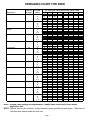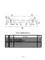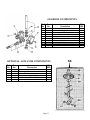
1
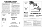
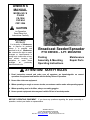
OWNER’S
MANUAL
MODEL NO.’S
CS-694
CS-1094
CSP-694
CSP-1094
CAUTION
For Operation
Read Rules And
Instructions Carefully
STATEMENT
OF POLICY
It is the policy of Worksaver,
Inc. to improve its products
where it is possible and
practical to do so. Worksaver,
Inc. reserves the right to make
changes or improvements in
design and construction at any
time without incurring the
obligation to make these
changes
on
previously
manufactured units.
Broadcast Seeder/Spreader
PTO DRIVEN – 3-PT. MOUNTED
Packing
Assembly & Mounting
Operating Instructions
Maintenance
Repair Parts
ATTENTION! SAFETY RULES
1. Read instruction manual and make sure all operators are knowledgeable on correct
operation of equipment and familiar with the Safety Rules of Operation.
2. Never allow riders on equipment.
3. When operating on rough or uneven terrain, use extreme caution and a safe operating speed.
4. When spreading seed or fertilizer, always use safety goggles.
5. Never operate equipment when anyone is within 50 feet of seeder/spreader.
BEFORE OPERATING EQUIPMENT : If you have any questions regarding the proper assembly or
operation, contact your dealer or representative.
WORKSAVER, INC.
P.O Box 100, Litchfield, IL. 62056-100
Phone: 217-324-5973 Fax: 217-324-3356
Web Site: www.worksaver.com E-mail: [email protected]
To the Owner/Operator/Dealer
All implements with moving parts are potentially hazardous. There is no substitute for a cautious, safe-minded operator who
recognizes the potential hazards and follows reasonable safety practices. The manufacturer has designed this implement to be used
with all its safety equipment properly attached, to minimize the chance of accidents.
BEFORE YOU START!!
Read the safety messages on the implement and shown in your manual. Observe the rules of safety and common sense!
Instructions
TRACTOR REQUIREMENTS
& PREPARATION
ASSEMBLY & MOUNTING
Mount the seeder on your tractor by sliding the
lift arm ball sockets over the seeder pull pins and
secure with linchpins (not furnished). Attach the
center link (not furnished) to the center link
bracket on the seeder using a center link pin (not
furnished), and secure it with a suitable linchpin.
Adjust the center link so that the seeder fan is
parallel to the ground.
The 3-pt. mounted broadcast seeder/spreader
with a PTO drive will fit most Categories I and some
larger Category 0 tractors. Larger Category II
tractors may also be used if the 3-pt. hitch lift arms
will narrow to 26 inches. Bushings will be needed to
fit the Category I (7/8” dia.) lift pins.
NOTE: Some Category 0 tractors have very short
lift arms or 5/8” diameter (Cat. 0) lift arm ball ends.
These tractors are not usually suitable.
NOTE: Use stabilizer bars, adjustable sway
chains, or sway blocks on your tractor lift
arms to keep the seeder/spreader from
swinging side to side. Adjust as tightly as
practical for best performance.
Check the tractor’s 3-pt. hitch.
The hitch
hydraulic system should be able to hold the lift arms
at a set height. If the hydraulic system leaks and
allows the lift arms to drop, then use stay straps to
lock the hitch into position.
Refer to your operator’s manual or dealer for any
adjustments necessary to put the 3-pt. hydraulic lift
system in good working order. (I&T shop manuals
will list most specifications and adjustment
instructions – available from most farm equipment
dealers.)
PTO INSTALLATION
In some cases it may be necessary to shorten
the PTO assembly to match your particular tractor.
The following procedure should be used:
(REFER TO FIG. 1)
Raise the tractor 3-pt. hitch so the input shaft
of the spreader gearbox is in line with the PTO
shaft on the tractor.
NOTE:
The Model CS-694 Seeder/Spreader
weighs 123 pounds and can hold up to 600 pounds
of fertilizer. The tractor needs to be large enough to
handle this possible 723-pound load safely. The
tractor may have to be equipped with front-end
weights to be properly counterbalanced.
Check the shield over the PTO stub shaft. Make
sure it is in good condition and bolted securely to
the tractor. Purchase a new shield if old shield is
damaged or missing.
CAUTION!
Be sure your tractor is in good condition. Read
all the safety precautions and make sure all
tractor operators are familiar with the safety
rules of operation.
PACKING
The CS-94 series of seeder/spreaders are
shipped assembled, except for the PTO drive shaft.
Page 2
CAUTION!
CAUTION!
Measure the distance between the ends of the two
shafts (Dimension “A”, Figure 1). Each half of the PTO
should be equal to dimension “A” minus two (2) inches.
If the driveline must be cut to a shorter length, clamp
driveline in a well-padded vise to prevent damage to the
shield (Figure 3). Cut the plastic shields 1 ½” shorte r
than the shafts.
When attaching PTO yoke to tractor PTO shaft, it is
important that spring-activated locking pin slides
freely and is seated in groove on PTO shaft. A
loose shaft could slip off and result in personal
injury or damage to equipment.
If your tractor has extra long lift arms, it may be
necessary to use a PTO extension so that you can use
the PTO shaft assembly provided. Be sure the PTO
assembly does not close too far (bottom out) if you use
a PTO extension.
Never raise or lower the seeder/spreader so that
the PTO shaft assembly will come apart.
CAUTION!
A heavy load can cause instability in driving a
tractor. Make sure the front of the tractor is
properly counter-balanced with weights. Always
drive slowly – especially around turns. An unstable
tractor could steer badly and possibly tip over,
causing injury or death.
Repeat the procedure to the other driveline half.
Remove all burrs and cuttings.
Apply multi-purpose grease to inside of outer
(female) driveline section. Assemble driveline and
install on tractor and spreader. Pull on each driveline
section to be sure yokes lock into place. Make certain
driveline shielding is in place and in good condition.
NOTE: A PTO driveline that is too long and
“bottoms out” could possibly cause severe damage
to the gearbox. It is VERY IMPORTANT to check the
proper PTO driveline length for your tractor.
Gearboxes damaged by incorrect PTO driveline
length are NOT covered by warranty.
NOTE: The use of a PTO shaft adapter or extension
could require that the PTO driveline be shortened a
considerable amount. If this is done, the driveline
halves may separate when the spreader is lowered
to the ground.
CAUTION!
Do not operate this equipment without shields
properly installed. This is for your protection, and
the manufacturer recommends the use of these
shields at all times.
Page 3
Fertilizers will vary as to weight and quality, which
may require additional adjustment by moving he
individual fan blades. Moving the blade tips forward will
carry more material to the left side. Moving the fan
blade tips back will allow more material to be spread to
the right.
Make small adjustment moves and check spread
after each adjustment.
NOTE: The gearbox is filled with lubricant and sealed
at the factory. If operated and stored properly, the
gearbox will provide a long, trouble-free service life. If
disassembly of the gearbox should ever be required, it
is important that the box be re-filled with a good quality
grease and that the box halves are resealed with a
silicone adhesive.
Obey All
Safety Warnings!
OPERATING INSTRUCTIONS
1.
2.
Right -hand or left-hand reference is determined by
standing at the rear of the seeder/spreader and
facing in the direction of travel of the tractor.
Check the register of the control lever indicator with
the seed gate (material gate). With the seed gate
closed, the control lever should be in its fully raised
position. Control lever setting listed on the spread
charts are to the TOP of the control lever.
The adjustable pointer/stop below the control
lever will point to a different setting as follows:
Top Side
of Control Lever
Pointer/Stop Reading
3.
2
3
4
5
4.5
4.75
6
7.25
DO NOT FILL HOPPER (especially with fertilizer)
and transport over long distances, as it may result in
packing, causing poor or erratic discharge.
4.
FOR BEST RESULTS use palletized fertilizer, as it
has little tendency to lump and causes little or no
dust.
5.
Be sure to sift or break up lumps found in some types
of granular fertilizer before filling hopper.
6.
Do not use on windy days, especially when spreading
fine grass seed.
7.
Be extremely careful if you are spreading herbicides,
as there is the possibility of wind drift or overthrow
into areas where serious crop/shrub damage could
occur.
Always follow instructions on chemical
package.
8.
Raise the seeder/spreader up so the spreader fan is
30-34 inches above the ground. This will give you
the best spreading performance. It is also best if the
seeder/spreader is tilted slightly forward so that the
spreader fan throws slightly upward. (Use the top
link to make this adjustment).
The PTO shaft
assembly should not be at a sharp angle – it should
operate fairly straight or level.
9. Adjust the tension on the control handle so it moves
with some resistance, but will remain where you set
it. Adjust the control handle stop so that at the end of
the field you can shut the seed gate and, after your
turn, re-open to your exact setting.
CAUTION!
Do not attempt to use your fingers to clear a jam.
Accidental closing of the feed gate could shear a finger
off, or leaving the PTO engaged could rotate the
agitator, which could pinch or amputate a finger. Be
sure that the tractor engine is shut off and the PTO
clutch is disengaged before doing any adjustment or
repair.
11. When broadcasting fertilizer, always start vehicle in
motion before opening feed gate. (Do not allow
vehicle to sit stationary with feed gate open). If
fertilizer is accidentally deposited too heavily in a small
area, soak down thoroughly with garden hose or
sprinkler to prevent burning.
SPREADING INSTRUCTIONS
1.
The control handle regulates the opening in the hopper
bottom. The calibrated scale determines the size of the
opening. Place the control lever at the desired setting.
2. The spread chart in this manual is an approximate
guide based on various forward speeds (from 4 mph to
7.5 mph). For accurate spreading, calibrate your
tractor to operate at the desired speed. A calibrated
speedometer is the best and most accurate. If your
tractor does not have a speedometer or its accuracy is
questionable, then you may calibrate in the following
manner:
Set out two markers 88 feet apart. Select proper
gear and adjust throttle speed to give the following
travel time as shown between the markers. NOTE:
You cannot adjust the throttle very much, as you
need to maintain 540 rpm PTO speed. (A plus or
minus 20 rpm could be tolerated).
1 MPH will travel 88 feet in 60 seconds
4 MPH will travel 88 feet in 15 seconds
5 MPH will travel 88 feet in 12 seconds
6 MPH will travel 88 feet in 10 seconds
7.5 MPH will travel 88 feet in 8 seconds
After selecting gear and throttle setting to give
desired speed, mark the throttle position in some
convenient manner. Check PTO speed to make
sure it is near 54 rpm.
3. Check rate chart for suggested setting for material type
to be spread.
4. You are now ready to make a trial run to assure
accurate results. Close the feed gates and put in a predetermined amount of material to be spread. Spread
this and check the results. Make final adjustments to
obtain desired results.
10. If, by chance, the agitator does become jammed,
open the feed gate all the way. By sticking a small
rod through the feed gate, the material jamming the
agitator can be loosened and removed. After the jam
is cleared, reset the feed gate and proceed. Always
stop tractor and disengage PTO before dislodging
material.
CAUTION!
KEEP ALL PERSONS AWAY FROM THE ROTATING
SPREADER FAN AND THE PTO SHAFT!
NEVER
OPERATE WHEN ANYONE IS WITHIN 50 FEET OF
SEEDER/SPREADER
Page 4
2. POOR SPREAD
A. Too much speed (over 560 PTO rpm) can cause
uneven spread.
B. PTO speed too slow (PTO rpm under 520 rpm)
will result in a narrow spread.
C. Bent fan blades.
D. Drive pin sheared or missing on fan hub.
E. Too windy for material being spread.
F. Agitator problems.
Feeding Even”.
Check tips under “Not
G. Operator not spacing spread runs properly for
correct overlap.
For best results, cover area twice over at
one-half recommended material usage rate.
The second time over, run halfway between
first spreading widths or in a criss-cross
pattern.
This method allows the most
complete and even coverage, as well as to
give operator a chance to adjust gate setting
to compensate for too thin or too heavy a
covering the first time over.
Three spreading possibilities
A simple adjustment of the lower level allows directioning
of distribution towards the right side or towards the left
side of the tractor operator.
MAINTENANCE
1. The hopper should be washed after use, especially after
use with corrosive material such as fertilizer, salt, or ice
melting compounds. When dry, oil thoroughly.
H. Seeder/spreader should run level or tilted slightly
forward. Make sure lift arms on tractor are
adjusted so one side is not lower than the other.
2. The gearbox is filled with lubricant and sealed at the
factory. If operated and stored properly, the gearbox will
provide a long, trouble-free service life. If disassembly of
the gearbox should ever be required, it is important that
the box be re-filled with a good quality grease and that
the box halves are resealed with a silicone adhesive.
I.
Running agitator when not spreading can result
in material being ground up and possibly packing
over control gate opening. You can “overagitate” material.
3. Grease PTO universal joints after every 8 hours of
operation.
Lubricate steel tube and shaft so they
telescope freely.
4. Always store seeder/spreader in a clean, dry place.
5. Before using, check to make sure all nuts and bolts are
tight.
6. Paint any bare metal or rusty spots for longer life.
HELPFUL
TROUBLE-SHOOTING TIPS
1. NOT FEEDING EVEN
A. Seed gate opening may be set too close for the
material being spread. To overcome, set the
opening larger and drive faster to obtain same
spread rate.
B. Check material for foreign matter.
C. Check agitator drive pin for shear.
Page 5
The CS-94 Series of seeder/spreaders have a two blade
knife type agitator as standard equipment. An optional long
wheel type agitator is available which will take care of air
pockets in the hopper, mix up the material, and deliver it to
the bottom knife type agitator. Order part number 420758 for
the optional long wheel agitator.
This optional agitator is recommended for use when
spreading powdery fertilizer, salt and sand. It may cause
seed damage if used on grass seed or grain.
SPREADING CHART FOR FERTILIZERS
FERTILIZER TYPE
Coarse Grain Fertilizers
Medium Grain Fertilizers
Fine Grain Fertilizers
Ammonium Nitrate
Urea (Carbamide)
PTO SPREAD TRACTOR QUANITY TO BE SPREAD, IN POUNDS PER ACRE
SPEED WIDTH SPEED
AT CONTROL LEVER SETTING INDICATED
(RPM) IN FEET (MPH)
1.5
2
2.5
3
3.5
4
4.5
5
5.5
40
540
2.5
97 139 246 414 516 640 789 935
5
48
69 129 204 260 320 392 472
7.5
37
53
85 139 175 218 260 323
34
540
2.5
85 122 175 329 467 597 739 825 945
5
51
73 105 170 236 303 376 417 478
7.5
43
62
73 113 163 198 253 286 325
540
26
2.5
60
85 122 204 340 440 551 647 770
5
32
46
61 108 178 224 280 324 396
7.5
21
30
41
93 122 153 193 220 263
540
33
2.5
61 226 377 563 724 896 1052 1242
5
28 116 190 284 366 448 525 622
7.5
23
74 124 191 244 298 352 422
540
28
2.5
77 110 303 458 669 818 1004 1171
5
41
59 150 231 300 411 500 590
7.5
26
37 100 150 221 275 336 392
NOTE:
Spread widths of fertilizer will vary according to type.
Always check actual spread width and application rate.
NOTE:
Spread Chart settings are approximate – always make trial run to check actual application rate.
WARNING
1. Be sure spinner is stopped during hitching.
2. Always keep away from rotating spinner.
3. Never work on top of or inside the hopper
unless tractor engine is shut off.
101023
Page 6
SPREADING CHART FOR SEED
MATERIAL
Alfalfa & Clover
SPREAD TRACTOR
WIDTH
SPEED
IN FEET
(MPH)
26
4
Barley
28
Bluegrass & Bermuda
Grass
18
Brome Grass
10
Fescue & Ryegrass
18
Lespedeza
32
Oats
28
Orchard Grass
12
Rice
33
Rye
33
Sudan Grass
33
Soybeans
40
Wheat
33
5
6
7.5
4
5
6
7.5
4
5
6
7.5
4
5
6
7.5
4
5
6
7.5
4
5
6
7.5
4
5
6
7.5
4
5
6
7.5
4
5
6
7.5
4
5
6
7.5
4
5
6
7.5
4
5
6
7.5
4
5
6
7.5
POUNDS PER ACRE (APPROXIMATE)
AT CONTROL LEVER SETTING INDICATED
1.5
2
2.5
3
3.5
4
4.5
5
14
48
118
11
9
7.5
39
32
26
95
79
63
90
72
60
48
5
3.5
3
2.4
20.5
16.5
13.5
11
7
6
5
4
11
9
7.5
6
11
9
7.5
6
14
11
9
7
37
30
25
20
72
45
36
24
12
9.5
8
6
34
27
22
18
22
18
15
12
45
36
30
24
21
17
14
11
87
70
58
47
58
47
39
31
70
56
46
37
107
86
71
57
151
121
100
81
186
149
124
99
19
15
12
10
74
59
49
39
71
57
48
38
131
105
87
70
140
112
93
75
86
69
57
46
92
74
61
49
253
203
169
135
135
109
90
72
186
149
124
99
227
182
151
121
127
102
85
68
151
121
100
80
150
120
100
80
198
159
147
106
170
136
113
90
111
89
74
59
200
160
133
106
NOTE: Spread Chart settings are approximate – always make a trial run to check actual
application rate.
NOTE: Material can vary as to density, foreign material content, particle size and shape. These factors
will affect both spread width and flow rate.
Page 7
EXPLODED PARTS DRAWING FOR CS SERIES SPREADERS
Page 8
REPAIR PARTS FOR CS SERIES SEEDER/SPREADERS
Ref. No
Part No.
1
2
3
4
5
6
7
8
9
10
11
12
13
14
15
16
17
18
19
20
21
22
23
24
24
24
24
25
26
27
28
29
30
31
32
33
34
35
36
37
38
39
40
41
42
43
44
45
46
420701
420702
420703
420704
420705
420706
420707
420708
420709
420710
420711
420712
420713
420714
420715
420716
420717
420718
420719
420720
420721
420722
420723
420724
420758
420726
420841
420727
420728
420729
420730
420731
420732
420733
420734
420735
420736
420737
420738
420739
420719
420741
420742
420743
420744
420745
420717
420747
420748
Description
Frame, XA
Bolt, Hex Head, M8 x 20, Zinc
Washer, Flat, 8mm, Zinc
Washer, Flat, 10mm, Zinc
Nut, Self-Locking, M10, Zinc
Washer, Bakelite
Lever, Adjustment
Handle, Rubber, 8 x 20
Brace, Right
Bolt, Hex Head, m10 x 65, Zinc
Spring, Pressure
Hair pin
Rod, Flow Adjustment
Block, Fixing
Indicator
Screw, Wing, M6 x 16, Zinc
Nut, Hex, M10, Zinc
Washer,, Lock, 10mm, Zinc
Nut, Hex, M8
Vane, Fan
Bolt, Hex Head, M8 x 16
Rod, Selector, RX-LX
Pin, Connection
Hopper, Steel 250 (6 bu.)
Hopper, Steel 400 (10 bu.)
Hopper, Poly 400 (10 bu.)
Hopper, Poly 250 (6 bu.)
Washer, for Hopper
Bolt, Carriage Head, M10 x 25, Zinc
Bar, Hopper Reinforcement
Nut, Self-locking, M8, Zinc
Agitator
Bolt, Hex Head, M8 x 45, Zinc
Guide Bushing, Agitator
Seed Disc, Upper (2 holes)
Distribution Disc, Lower (3 holes)
Washer, Special
Snap Ring, D.32 E
Spreading Disc (Spinner)
Roll Pin (Special Double)
Nut, Hex, M8, Zinc
Pin, Adjustment
Guard
Brace, Left
Bolt, Hex, M10 x 25, Zinc
Bolt, Hex, M10 x 100, Zinc
Nut, Hex, M10, Zinc
Gearbox, 3-Hole (Complete)
PTO Assembly (Complete)
Page 9
No.
Req'd
1
2
4
7
1
1
1
1
1
1
1
4
1
1
1
1
9
12
8
4
8
1
1
1
1
1
1
1
5
1
1
1
1
1
1
1
1
1
1
1
3
1
1
1
4
3
3
1
1
PTO COMPONENTS
Ref. No
Part No.
46
63
64
65
66
67
68
69
70
420748
420764
420765
420766
420767
170804
3814091
170806
101081
Description
PTO Assembly, Complete
PTO Half, Tractor End
Plastic Shield Assembly, Outer
PTO Half, Implement End
Plastic Shield Assembly, Inner
Yoke, 1-3/8-6B Spline
PTO Cross Repair Kit
Push Pin Repair Kit, Yoke
Decal, Driveline Entanglement
Page 10
No.
Req'd
1
1
1
1
1
2
2
2
1
GEARBOX COMPONENTS
Ref.
No.
Part
No.
45
47
48
49
50
51
52
53
54
55
420747
420749
420750
420751
420752
420753
420754
420755
420756
420719
OPTIONAL AGITATOR COMPONENTS
Ref.
No.
Part
No.
56
57
58
59
60
61
420725
420759
420760
420761
420710
420717
Description
Agitator, Complete
Wheel, Agitator
Washer, Flat, M12
Nut, Self-Locking, M12, Zinc
Bolt, Hex Head, M10 x 65, Zinc
Nut, Hex, M10, Zinc
NO.
REQ.
1
1
2
1
1
1
Page 11
Description
Gearbox, 3-Hole (Complete)
Gearbox Half, Right Hand
Shaft, Output Assembly
Oil Seal, 25 x 37 x 5
Bearing, 6205
Gearbox Half, Left Hand
Bolt, Hex Head, M8 x 45
Snap Ring, D.25 E
Shaft, Input Assembly
Nut, Hex, M8
NO.
REQ.
1
1
1
1
2
1
3
1
1
3
SAFETY PRECAUTIONS
MOST ACCIDENTS OCCUR BECAUSE OF NEGLECT OR CARELESSNESS.
AVOID NEEDLESS ACCIDENTS BY FOLLOWING ALL OF THE SAFETY PRECAUTIONS LISTED BELOW.
1.
Machinery should be operated only by those who
are responsible and are authorized to do so.
2. Stop the engine, lower all equipment, lock the
brakes, and remove the ignition key before
dismounting from the tractor.
3. Never stand between tractor and implement while
tractor is being backed to hitch.
4. Loose fitting clothing should not be worn, to avoid
catching on various parts.
5. Detach implement in area where children normally
do not play.
6. When performing adjustments or maintenance on
an implement, first lower it to the ground or block it
securely at a workable height.
7. Only a qualified operator should be permitted on
tractor when in operation; no riders allowed.
8. Make certain everyone is in the clear before
starting tractor or raising or lowering equipment.
9. Operate the tractor and implement only while
seated in the driver’s seat.
10. Reduce speed when transporting mounted
implement to avoid bouncing and momentary loss
of steering control.
Broadcast
Seeder/Spreader
OWNER’S
MANUAL
MODEL NO.’s
CS-694
CS-1094
CSP-694
CSP-1094
WHEN ORDERING
REPAIR PARTS, ALWAYS
GIVE THE FOLLOWING
INFORMATION:
1. PART NUMBER
2. PART DESCRIPTION
3. MODEL NUMBER
4. NAME OF ITEM
MARCH 2001
11. A heavy load can cause instability of the tractor.
Use extreme care during road travel. Slow down
on turns and watch out for bumps. Tractor may
need front counter-weights to counter-balance
the weight of the implement.
12. Reduce speed on hillsides or curves so there is
no danger of tipping.
13. Avoid driving too close to the edge of ditches or
creeks.
14. Do not transport implement on public toads
without reflectors and slow moving vehicle
emblem in daylight and with approved warning
lights at night and other periods of poor visibility.
15. Due to the width of some implements, use extra
caution on highways, farm roads, and when
approaching gates.
16. Always be sure the implement is in the proper
position for transport.
17. Keep alert and watch the front as well as the rear
when working with the implement.
Please work, drive, play, and live each day with care and
concern for your safety and that of your family and fellow
citizens.
MAKE EVERY DAY
A HOLIDAY
FROM ACCIDENTS
3-Pt. Broadcast Seeder/Spreader
WORKSAVER LIMITED WARRANTY
Worksaver warrants its implements, parts and accessories to be free from defects in
materials and workmanship for a period of six (6) months from the date of purchase. Upon
written approval, Worksaver will repair or exchange without charge any part, which upon
examination by Worksaver or its authorized agent, shall disclose to be defective.
This does not apply to (1) parts that have worn out in normal use, (2) parts broken because
of improper assembly or operation by the customer, (3) parts accidentally damaged, (4) failure
of parts traceable to improper care, (5) parts failing through use of implement for purposes
other than those for which it was designed.
The obligations assumed by Worksaver and the limitations expressed herein are in lieu of
all other warranties expressed or implied.
WORKSAVER, INC.
P.O. Box 100, Litchfield, IL. 62056-0100
Phone: 1-217-324-5973 Fax: 1-217-324-3356
Web Site: www.worksaver.com
E-Mail: [email protected]