1
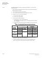
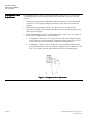
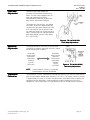
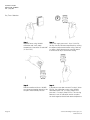
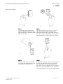
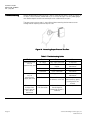
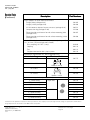
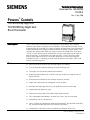
Tec
Technical In
Instruction
Document No. 155-067P25
TH 192-3
Rev. 1, July, 1999
Powers™ Controls
TH 192 DN Day-Night and
TH 192 DNV Day-Night-Vent
Room Thermostat
60
70
80
TH0357R1
70
70
80
DAY
50
POWERS
Desc
escription
The TH 192 DN & DNV thermostats are proportional single output, dual set point,
2-pipe or 3-pipe (high air capacity) sensor controllers. Each thermostat includes a wall
mounting plate for installation in a variety of rough-in terminal boxes. Sensitive bimetals
respond to temperature change to modulate control air through a flapper nozzle. Two
set point dials are provided. When the supply air pressure changes from 18 to 25 psi
(124 to 172 kPa), the thermostat automatically switches from the day to the night set
point respectively. Air connections are made with 5/32” (4 mm) OD plastic tubing,
directly to the thermostat chassis for retrofit applications or with plug-in adapters
(provided with the TH 192 rough-in terminal box or optional accessories) which slide
into the wall mounting plate.
Features
ures
•
Direct and reverse acting for day and night modes (DN models)
•
Two separate adjustable temperature set point indicating dials
•
Two highly sensitive bimetal thermostatic elements
•
Operating mode automatically switches from day to night on change of main air
supply pressure
•
Manual override selector ensures off-hour occupancy comfort
•
Single screw adjustment for changeover switch set point
•
Individual field adjustable sensitivity with graduated scale for each mode
•
Integral field adjustable limit stops
•
Control pressure test port accessible without removing cover
•
Easily replaceable thermometer, set point dials, filters, and restrictor plate
•
Fahrenheit or Celsius set point dials
•
•
Covers available for concealed or exposed thermometers and for either concealed,
key, or exposed knob adjustment and set point adjustment
Standard plastic thermostat covers provide desert beige or white finish
Siemens Building Technologies, Inc.
Landis Division
Technical Instruction
Document No. 155-067P25
Rev. 1, July, 1999
Optional Design
Features
ures
Appli
pplic
lication
•
Fixed temperature limit stops meet government specifications
•
Metal covers available in standard configurations with a variety of finishes
•
Competitor adapter mounting kits available
•
All thermostat chassis available with optional 1/2” large set point adjustment knobs
TH 192 DN & DNV thermostats provide day to night (or weekend) temperature setback
to control pneumatic valve and damper actuators in heating and cooling applications
(Figure 1) such as air conditioners, space heaters, unit ventilators, and air volume
controllers.
The day-night thermostat is particularly useful in locations where all rooms in a zone are
not vacated at the same time. Using time clocks on evenings and weekends to reset
the control system to the night mode ensures optimum energy management. When a
zone is operating in maximum economy mode at night, an occupant can reset an
individual space to day temperature by switching a manual override. During night
control, the TH 192 DNV provides a separate output signal (full air supply) which allows
ventilation to occur.
TH 192 DN & DNV thermostats maintain maximum economy and occupant comfort
automatically as a day progresses from the day time set point (65 to 68°F, 18 to 20°C)
to the night time set point (55 to 60°F, 13 to 16°C). The thermostats are available with
covers that conceal or expose the set point adjustment dials.
Figure 1. Typical TH 192 DN & DNV Thermostat Applic
lications.
Table 1. Typical TH 192 DNV Thermostat Applic
lication.
Page 2
Chassi
ssis Port R2 Pressu
ssure
0 Psig (0 kPa)
Operation Mode (Air Suppl
pply)
Day (S = 18 Psig, 124 kPa)
Switching Relay Conn
onnection
B-D
0 Psig (0 kPa)
Night Occupied
B-D
Full Air Supply
Night (S = 25 Psig, 172 kPa)
A-D
Siemens Building Technologies, Inc.
Landis Division
TH 192 DN Day-Night and DNV Day-Night-Vent Room Thermostat
Technical Instruction
155-067P25
Rev. 1, July, 1999
Piping
Figure 3. TH 192 DNV
Thermostat Conne
nnections.
Figure 2. TH 192 DN
Thermostat Conne
nnections.
Produc
duct Numbers
and Orde
rdering
Information
Chassis
See Table 2 for product number and ordering information on TH 192 DN & DNV
thermostat chassis.
1. Is a Fahrenheit or Celsius scale required?
2. Is the day and night time control direct or reverse acting?
3. Is a separate, full supply output signal required for ventilation control?
4. Where is set point adjustment knob located?
a.
Adjustment knob located at bottom of chassis.
b. Adjustment knob on front with 1/2” large exposed knob.
Table 2. TH 192
192 DN & DNV Thermostat Chassi
ssis Part Numbers.
Chassi
ssis with Wall Plate
Fahrenhei
Celsius
enheit
Exposed
Exposed
Exposed at
Exposed at
Botto
ttom of 1/2” Knob on
ttom of 1/2” Knob on Botto
Cover *
Cover
Cover *
Cover
192-204
192-204K
192-224
192-224K
Two or
Day and Night are
Three Pipe
Direct Acting
Relay
Day and Night are
192-205
192-205K
192-225
192-225K
Conne
onnection
Type
Contr
ontro
trol
Action
Reverse Acting
Day and Night are
Direct Acting
with Night Vent
*
192-206
192-206K
192-226
192-226K
This feature requires a key set point adjustment cover (or key type cover).
See Table 3.
Siemens Building Technologies, Inc.
Landis Division
Page 3
Technical Instruction
Document No. 155-067P25
Rev. 1, July, 1999
Covers
See Table 3 for product number and ordering information on TH 192 DN & DNV
thermostat covers.
1. Is the set point adjustment exposed for customer adjustment or concealed to
prevent alteration of setting?
2. Is the thermometer exposed or concealed?
3. Is the set point indication exposed or concealed behind cover?
4. Is a plastic or zinc cast metal cover required?
a.
Plastic covers order 192-2XX.
b. Metal covers order 192-3XX.
5. Is finish of cover standard or optional?
a.
Standard cover is plastic, desert beige color.
For white plastic cover option, add “W” suffix code to cover part number
(e.g., 192-256W).
b. Optional covers are plastic or metal and available in a variety of colors per
Table 3.
Table 3. TH 192
192 DN & DNV Thermostat Cover Part Numbers.
Cover Conf
onfigur
guration
Set Point
Adjustment
ent
Concealed
Ther
hermometer
Concealed
Set Point
Indicat
cator
Concealed
Exposed
Exposed
Cover Part Number
(See Note 2)
Standard
Standard
Plastic Cover
Metal Cover
192-262
192-362
192-264
192-364
192-269
192-369
Key
(See Note 1)
Concealed
Exposed
192-270
192-370
Key (Night),
Exposed (Day)
(See Note 1)
Exposed
192-271
192-371
1. Key set point adjustment cover required for all thermostat chassis with
optional 1/2” large set point adjustment knobs.
2. To order an optional thermostat cover finish, add the appropriate suffix
letter listed in Table 4 to the end of the part number listed in Table 3.
Page 4
Siemens Building Technologies, Inc.
Landis Division
TH 192 DN Day-Night and DNV Day-Night-Vent Room Thermostat
Technical Instruction
155-067P25
Rev. 1, July, 1999
Table 4. TH 192
192 DN & DNV Thermostat
Suffi
ffix Letters for Optional Cover Part Numbers.
NOTE: For color samples, order color reference guide 152-178P10.
Cover
Cover Finish
Part
Cover
Part
N um b er
Material
N um b er
Material
Suffi
Suffi
ffix
ffix
Lette
Lette
tter
tter
Desert Beige
D
None
Plastic
Metal
(standard)
(optional)
Specifications
#10 Special
Bronze
W
Plastic
(optional)
White
E
Brushed
Electro-plated
Satin Chrome
None
Metal
(standard)
Desert Beige
F
Sierra Gold
A
Metal
(optional)
#1 Silver
G
Brushed
Aluminum
B
#5 Satin Chrome
H
White
C
#7 Light Statuary
Bronze
Control action
Operating ranges
Supply air pressure, maximum
Normal air supply pressure
Day
Night
Sensitivity adjustment
Nominal air consumption, two-pipe
Temperature
Storage temperature
Ambient operating temperature
Temperature response
Dial graduations
Factory settings
Calibration @ 72°F (22°C)
Sensitivity
Limit stop adjustment
Standard cover
Shipping weight
Dimensions
Siemens Building Technologies, Inc.
Landis Division
Cover Finish
See Table 2.
45 to 85°F (7 to 30°C)
30 psi (207 kPa)
18 psi (124 kPa)
25 psi (172 kPa)
1 to 4 psi/°F (12 to 50 kPa/°C)
25 scim (6.8 ml/sec)
-10 to 140°F (-23 to 60°C)
40 to 140°F (4 to 60°C)
0.1°F (0.06°C)
2°F (1°C)
7.5 psi (52 kPa)
2.5 psi/°F (31 kPa/°C)
45 and 85°F (7° and 30°C)
Cycolac, desert beige
0.7 lbs. (0.3 kg)
See Figure 4.
Page 5
Technical Instruction
Document No. 155-067P25
Rev. 1, July, 1999
Access
Accesso
essories
See the following Technical Bulletins for information on accessories.
Technical Bulletin
TB 237 Terminal Kits
TB 213 Aspirator Wall Box Kit
TB 214 Adapter Kits
TB 193 Guard Kit
TB 241 Test Head Kit
TB 167 Restrictors
Document
ent Number
155-244
155-245
155-231
155-222
155-255
155-213
Dimensions
Figure 4. TH 192 DN & DNV Dimensions in Inches (Millim
illimeters).
Operation
Day-Night Operation
The TH 192 DN thermostat is either direct or reverse acting for both day and night
operating modes. In a direct acting thermostat, an increase in temperature increases
the control air pressure and a decrease in temperature decreases the control pressure.
In a reverse acting thermostat, an increase in temperature decreases the control air
pressure and a decrease in temperature increases the control pressure.
The TH 192 DN provides two separate bimetal elements; one for day temperature and
one for night temperature. Each bimetal element operates independently of the other.
Use of two different supply air pressures accomplishes changeover from day to night
temperature. A supply pressure of 18 psi (124 kPa) or 25 psi (172 kPa) positions a
changeover switch so a changeover relay operates in the day or night mode
respectively.
TH0396R1
OUTPUT PRESSURE
15 PSI
(103 KPA)
REVERSE ACTING
7.5PSI
(52 KPA)
3 PSI
(21 KPA)
0
DIRECT ACTING
FACTORY SET
POINT CONDITIONS
45 50 55 60 65 70 75 80 85F
7
13
18
24
30C
TEMPERATURE
Figure 5. TH 192 DN & DNV Input/Output Characteristics.
Page 6
Siemens Building Technologies, Inc.
Landis Division
TH 192 DN Day-Night and DNV Day-Night-Vent Room Thermostat
Manual Selector Switch
A manual selector switch allows an individual thermostat to control at its day setting
even though the remainder of the system is controlling at its night setting.
•
•
•
•
Day-Night-Vent Operation
Technical Instruction
155-067P25
Rev. 1, July, 1999
In the normal AUTO position, the manual selector switch does not interfere with air
passage to the changeover relay.
To manually set the selector switch to the DAY position, push selector in until it
latches and the handle points downward. In the latched DAY position, the manual
selector switch seals off air to the changeover relay.
To manually reset the selector switch, rotate the handle until it unlatches and
returns to the normal AUTO position.
Manual Selector Switch resets automatically when supply pressure changes back to
day time control.
The TH 192 DNV provides a supplementary air line connection at the back of the
thermostat.
NOTE:
This third line feature cannot be added to a TH 192 DN in the field.
The vent line provides either 0 or 25 psi (0 or 172 kPa) pressure via the manual selector
switch to pilot auxiliary controls. For example, a unit ventilator can provide continuous
full day operation when the space is occupied and intermittent night operation when the
space is unoccupied.
TH 192 DN & DNV
Thermostat Details
Figure 6. TH 192 DN & DNV Thermostat Details
ils.
Thermometer
Calibr
libra
bration
1. Use a test thermometer to read the current room temperature.
2. Place a screwdriver in the center of the thermometer assembly (Figure 6). Carefully
rotate thermometer assembly until pointer tip indicates the correct room
temperature.
NOTE:
Siemens Building Technologies, Inc.
Landis Division
Avoid breathing on or touching the bimetal spiral since this influences the
temperature reading.
Page 7
Technical Instruction
Document No. 155-067P25
Rev. 1, July, 1999
Change
ngeover Point
Adjustment
The changeover point is factory set to occur between 19 and 22 psi (131 and 152 kPa).
The changeover point can be field adjustable to occur between 14 and 22 psi (96 and
152 kPa).
1. Connect pressure gauge or manometer to measure supply pressure to thermostat.
Use 30 psi (207 kPa) supply through a positioning switch so pressure can be fully
variable.
2. Determine current change over point. Turn day dial so day and night control
pressures are different. Then note the changeover point on the control gauge as the
supply pressure changes.
3. Remove thermometer for access to changeover adjust screw. Use a 1/16’ Allen Hex
Key to adjust changeover adjust screw as follows:
a.
If changeover is too high, turn off supply pressure and rotate changeover adjust
screw clockwise. One turn decreases changeover point by about 3 psi (20 kPa).
Turn on supply pressure and recheck to verify new changeover point.
b. If changeover is too low, turn off supply pressure and rotate changeover adjust
screw counterclockwise. One turn increases changeover point by about 3 psi (20
kPa). Turn on supply pressure and recheck to verify new changeover point.
Figure 7. Changeover Point Adjustment.
Page 8
Siemens Building Technologies, Inc.
Landis Division
TH 192 DN Day-Night and DNV Day-Night-Vent Room Thermostat
Lim
Limit St
Stop
Adjustment
Technical Instruction
155-067P25
Rev. 1, July, 1999
Thermostat limit stops define the
minimum and maximum thermostat set
points. The limit stops engage in the set
point cam gear teeth and cause
interference between the set point cam
gear and the adjustment knob gear.
To change limit stop settings, use needle
nose pliers to pull limit stop between the
set point cam gear teeth. Rotate limit stop
to its new position. Do not pull limit stop
any more than necessary to clear the gear
teeth. Changing the limit stop position one
gear tooth changes the limit stop setting
by 1-1/3°F (0.7°C).
Figure 8. TH 192 DN & DNV
Limit Stop Adjustments.
Sensitivity
Adjustment
To change thermostat sensitivity, use a flat blade
screwdriver to carefully move the sensitivity slide to
the desired position as follows:
Graduation
closest to the
rigid end of
the bimetal
element
4 psi/°F
(50 kPa/°C)
NOTE:
Thermostat
Calibr
libra
bration
Graduation
closest to the
minimum
(MIN) end of
the bimetal
element
1 psi/°F
(12 kPa/°C)
Figure 9. TH 192 DN & DNV
Sensitivity Adjustment.
If the thermostat sensitivity is adjusted,
the thermostat must be recalibrated.
The thermostat is factory calibrated to a control pressure of 7.5 psi (52 kPa) when the set
point and the ambient temperature are both at 72°F (22°C). The factory sensitivity setting
is approximately 2.5 psi/°F (31 kPa/°C). No adjustments are required if these settings are
appropriate for the application. If the thermostat has been tampered, the sensitivity
changed, or is out of adjustment, use the following steps to re-calibrate the instrument.
Siemens Building Technologies, Inc.
Landis Division
Page 9
Technical Instruction
Document No. 155-067P25
Rev. 1, July, 1999
Day Time Calibration
Page 10
S t ep 1 —
Remove cover using 192-632
calibration tool. Verify room
temperature is between 70 and 80°F
(21 and 27°C).
S t ep 2 —
Verify that supply pressure is 18 psi (124 kPa).
Set day time dial to room temperature by turning
the exposed adjustment knob or using a hex key
as shown. Allow thermostat to stand for about
five minutes to adjust to the new setting.
S t ep 3 —
Moisten needle and insert 192-633
test gauge and needle adapter in the
test port. Read control pressure.
S t ep 4 —
If control pressure does not read 7 to 8 psi (48 to
55 kPa), turn calibration screw using 192-632
calibration tool or 1/8” (3.2 mm) wrench until
pressure is 7 to 8 psi (48 to 55 kPa). The sensing
element is now in calibration and the set point
can be changed to the desired room temperature.
Siemens Building Technologies, Inc.
Landis Division
TH 192 DN Day-Night and DNV Day-Night-Vent Room Thermostat
Technical Instruction
155-067P25
Rev. 1, July, 1999
Night Time Calibration
S t ep 1 —
If not already done, remove cover
using 192-632 calibration tool. Verify
room temperature is between 70 and
80°F (21 and 27°C).
S t ep 2 —
Verify that supply pressure is 25 psi (172 kPa).
Set night time dial to room temperature by
turning the exposed adjustment knob or using a
hex key as shown. Allow thermostat to stand for
about five minutes to adjust to the new setting.
S t ep 3 —
Moisten needle and insert 192-633
test gauge and needle adapter in the
test port. Read control pressure.
S t ep 4 —
If control pressure does not read 7 to 8 psi (48 to
55 kPa), turn calibration screw using 192-632
calibration tool or 1/8” (3.2 mm) wrench until
pressure is 7 to 8 psi (48 to 55 kPa). The sensing
element is now in calibration and the set point
can be changed to the desired room temperature.
Siemens Building Technologies, Inc.
Landis Division
Page 11
Technical Instruction
Document No. 155-067P25
Rev. 1, July, 1999
Troubl
ubleshooting
Before troubleshooting thermostat per Table 5, make certain there is clean dry supply air
at 18 psi (124 kPa) for day control and 25 psi (172 kPa) for night. Use test probe gauge
and needle adapter to measure control pressure at thermostat test port.
The output pressure test port is accessible without removing the thermostat cover
through the 8th opening from the top left side.
Figure 10. Accessing Output Pressu
ssure Test Port.
Table 5. Troubleshooting Guide.
Problem
Control pressure
stays at
approximately zero
Control pressure
stays at
approximately
supply pressure
Excessive air
leakage from
exhaust port on
left side of
thermostat
Page 12
Chec
heck
Air supply
Cause
Low supply pressure
Action
As required
Nozzle or flapper
Dirt on nozzle or
flapper
Clean nozzle or replace
thermostat
Restrictor
Clogged restrictor
Replace restrictor
Calibration
Out of calibration
Recalibrate
Nozzle
Clogged nozzle
Clean nozzle or replace
thermostat
Calibration
Dirt on either supply
or exhaust valve seat
Alternately close and
open nozzle by gently
pushing down the
bimetal
Supply and return
line connection
Connections are
interchanged or
connection to port is
incorrect
As required
Siemens Building Technologies, Inc.
Landis Division
TH 192 DN Day-Night and DNV Day-Night-Vent Room Thermostat
Chassi
ssis Tube
ube
Conne
nnector and
Rest
estrictor Plate
Replacement
Technical Instruction
155-067P25
Rev. 1, July, 1999
1. Remove thermostat chassis from wall. Terminal does not have a ball check valve.
NOTE:
You must close off the supply air. For example, use a connector with the supply
air terminal plugged.
2. Remove two Phillips head screws from connector on back of thermostat chassis. Pull
connector out of recess. If necessary, pry connector loose with a screw driver, but be
careful not to damage restrictor plate and gasket.
3. Remove gasket from under connector. Remove restrictor. Remove second gasket from
under restrictor.
4. Use restrictor replacement kit 192-321 to replace gasket, restrictor, and second gasket.
NOTE:
The restrictor plate is keyed to ensure proper orientation during installation.
5. Remove filters from existing connector and insert in new connector. Or, if filters are
dirty, use restrictor replacement kit 192-321 to replace filters.
6. Use chassis tube connector replacement kit 192-525 to replace connector and
mounting screws.
Servic
vice Parts
The following chart lists accessory parts and tools available for thermostat service.
Description
Dial thermometer (-40 to 140°F, -40 to 60°C) with pocket case
Part Number
141-0573
Basic pneumatic calibration kit with thermometer, gauge, squeeze
bulb, fittings, and case
832-177
Test head kit
832-179
Calibration tools
832-178
Test probe to check pressure with cover on
Needle probe with 1-1/2” diameter gauge 0-30 psig
(0-200 kPa) and calibration/cover wrench
192-633
Needle probe, no gauge (package of five)
192-759
1-1/2” diameter gauge , 0-200 kPa,
back connected 1/8” NPT male
142-0344
1-1/2” diameter compound gauge, 0-30 psig/0-200 kPa,
back connected 1/8” NPT male
142-0373
1-1/2” diameter compound gauge, 0-30 psig/0-200 kPa,
bottom connected 1/8” NPT male.
Replacement for use with 192-633
142-0426
Chassis tube connector replacement kit with mounting screws
(material for 10 thermostats included)
192-525
Restrictor plate replacement kit with filters and gasket
(material for 10 thermostats included)
192-321
Siemens Building Technologies, Inc.
Landis Division
Page 13
Technical Instruction
Document No. 155-067P25
Rev. 1, July, 1999
Servic
vice Parts
(Continued)
Desc
escription
Part Numbers
Plug-in adapters for quick thermostat removal
Straight, blue (package of 20)
192-485
Straight, white (package of 20)
192-486
Air link connects adapters for pressure tests (package of 20)
192-501
Compression ring (package of 100)
141-388
Elbow (provides quick return for wall surface mounting), blue
(package of 20)
192-487
Elbow (provides quick return for wall surface mounting), white
(package of 20)
192-488
20 scim (5.4 ml/sec) restrictors for 1-pipe systems (package of 5).
(1/4 “, 6.4 mm, OD plastic barb unless noted.)
Brass coupling, 1/8” NPT (1 only).
184-040
Coupling
184-116
Tee
184-113
Pre-piped dual tee for dual 1-pipe systems
184-130
Replacement thermometer kits, brown (packages of 5)
Scal
Ther
cale Range
hermostat Model
192-775
TH0443R1
45° to 85°F
10° to 30°C
192-776
Model 3 and Up
192-786
TH0442R1
45° to 85°F
10° to 30°C
192-785
Models 1 and 2
Replacement set point dials (packages of 10)
°F, Direct Acting
Right Side
192-779
°F, Reverse Acting
192-780
°C, Direct Acting
192-783
°C, Reverse Acting
192-784
°F, Direct Acting
Left Side
192-777
°F, Reverse Acting
192-778
°C, Direct Acting
192-781
°C, Reverse Acting
192-782
Information in this publication is based on current specifications. The company reserves the right to make changes in specifications and models as
design improvements are introduced. © 1999 Siemens Corporation
Siemens
ens Build
ilding Techno
hnologi
ogies, Inc.
Landis Division
1000 Deerfield Parkway
Buffalo Grove, IL 60089-4513
USA
Document No. 155-067P25
Printed in the U.S.A. (origin)
Page 14