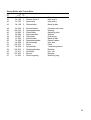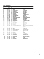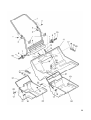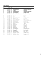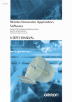
1
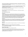
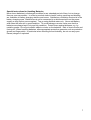
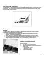
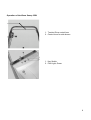
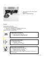
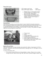
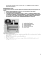
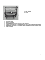
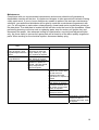
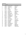
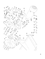
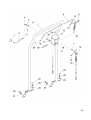
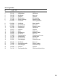
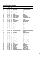
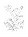
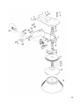
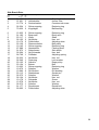
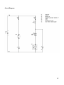
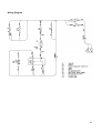
Kleen Sweep 35W
Sweeper
OPERATION
SERVICE
Model
HM35BQP
PARTS
CARE
This manual is furnished with each new MINUTEMAN KLEEN SWEEP 35WTM. This provides
the necessary operating and preventive maintenance instructions. Operators must read and
understand this manual before operating or servicing this machine.
This machine was designed to give you excellent performance and efficiency. For best results
and minimal cost, please follow the general guidelines below:
Operate the machine with reasonable care.
Follow the manufacturers suggested maintenance instructions as provided in this booklet.
Use original Minuteman supplied parts.
Technical Specifications
Dimensions and Weight
Length, Total: 54.72" (1.39mm), Width, Total: 31.78" (840mm)
Height Over Handlebar: 40.57" (1030mm)
Weight, Without Batteries: 208lbs (95kg)
Weight, With Batteries: 342lbs (155kg)
Traveling and Sweeping Performance
Speed, Forward: 3mph (4.83km/h)
Sweeping Width, With Side Broom: 34” (850mm)
Sweeping Capacity With Side Broom, Max.: 36.6 sq. ft (3400m2)
Theoretical Max Rate of Climb: 15% grade
Filter System
Filter Area: 1.5 ft2 (0.139 m2)
Number of Filter Elements: 1 piece
Dust Extractor Fan
Speed: 2500rpm
Broom Roller
Length / Dia.: 28.61/9.84" (700 / 250mm)
Wear Limit (approx.): 9" (230mm)
Speed: 510rpm
Sweeping Track Width: 2" (50mm)
Rows of Bristles: 10
Side Broom
Diameter: 12.25" (47mm)
Speed: 94rpm
Dirt Hopper
Capacity: 12.5 Gal (47liters)
Tires
Caster Wheel, Front, Dia.: 4.92" (125mm)
Rear Wheels, Dia.: 5.9" (150mm)
Electric Drive System
DC-Motor Voltage: 12V
Power Rating / Speed: 550W / .75 Hp
Current Dissipation: 57A
Noise Emission
Sound pressure level: 64dB (A)
2
3
TABLE OF CONTENTS
Operation, Illustration, Spare Parts, and Maintenance
IMPORTANT SAFETY INSTRUCTIONS ............................................................. 5
INSPECTION ................................................................................................................ 6
KLEEN SWEEP 35W – HOW IT WORKS.......................................................................... 8
ASSEMBLY .................................................................................................................. 8
INSTALLING / SERVICING THE BATTERIES ....................................................................... 8
OPERATION OF THE KLEEN SWEEP 35W ....................................................................... 9
CONTROLS........................................................................................................ 10
HOW TO USE THE KLEEN SWEEP 35W ........................................................................ 11
SWEEPING WITH THE KLEEN SWEEP 35W.................................................................... 11
EMPTY DIRT HOPPER ................................................................................................. 12
TRACTION DRIVE ....................................................................................................... 12
REPLACE BROOM ROLLER.......................................................................................... 12
ADJUST SWEEPING TRACK ......................................................................................... 13
REPLACING THE SIDE BROOM ..................................................................................... 13
REPLACING THE SIDE BROOM V-BELT ......................................................................... 14
FILTER SYSTEM – DUST EXTRACTOR .......................................................................... 14
MAINTENANCE ................................................................................................. 16
EXPLODED VIEWS ........................ FEHLER! TEXTMARKE NICHT DEFINIERT.
TRACTION DRIVE ............................................... FEHLER! TEXTMARKE NICHT DEFINIERT.9
TRAVEL DRIVE .......................................................................................................... 23
CHASSIS - COVERING ................................................................................................ 25
STEERING HANDLE .................................................................................................... 29
SWEEP ROLLER WITH TRAVEL DRIVE .......................................................................... 31
FILTER INSTALLATION................................................................................................. 35
LIFTER HOPPER ........................................................................................................ 37
SIDE BRUSH DRIVE .................................................................................................... 39
CIRCUIT DIAGRAM ........................................................................................... 40
WIRING DIAGRAM ............................................................................................ 41
LIMITED WARANTY .......................................................................................... 42
4
IMPORTANT SAFETY INSTRUCTIONS
Operators must read and understand this manual before operating or maintaining this
machine.
Do not operate this machine in flammable or explosive areas.
The following information below may cause a potential hazard to the operator and equipment.
Read this manual carefully and be aware when these conditions can exist. Take necessary
steps to locate all safety devices on the machine and train the personnel operating the
machine. Report any machine damage or faulty operation immediately. Do not use machine
if it is not in proper operating condition.
FOR SAFETY DURING OPERATION:
Keep hands and feet clear of moving parts while machine is in operation.
Make sure all safety devices are in place and operate properly. All covers, doors and latches
must be closed and fastened before use.
During operation, attention should be paid to other persons in the work area and especially if
small children are present.
Electric motors and components can cause an explosion when operated near explosive
materials or vapor. Do not operate this machine near flammable materials such as solvents,
thinners, fuels, grain dust, etc.
Store or park this machine on a level surface only, with parking brake engaged. To prevent
unauthorized use, machine should be stored or parked with the key removed.
This machine is designed for level operation only. Do not operate on ramps or inclines over
15% grade.
This machine is not suitable for picking up hazardous dusts.
Use caution when moving this machine into areas that are below freezing temperatures. Any
water in the tanks or hoses can cause damage to the machine.
FOR SAFETY WHEN SERVICING or MAINTAINING MACHINE:
For safety reasons, the engine hood is equipped with a safety switch. Function of this safety
switch must not be bypassed.
Stop on level surface.
Disconnect the power to the machine when charging batteries or during installation or removal
of brushes.
Avoid moving parts. Do not wear loose jackets, shirts, or sleeves when working on machine.
5
Avoid contact with battery acid. Battery acid can cause burns. When working on or around
batteries, wear protective clothing and safety glasses. Remove metal jewelry. Do not lay tools
or metal objects on top of batteries.
Charging batteries generates explosive gasses. Do not charge batteries when open flames
or sparks are present. Do not smoke. Make sure the charger is turned off before
disconnecting it from the machine.
Charge the batteries in a well-ventilated area with the battery cover removed completely.
Do not clean machine with a pressure washer.
Authorized personnel must perform repairs and maintenance. Use Minuteman supplied
replacement parts.
SAVE THESE INSTRUCTIONS
Proper Use
The Kleen Sweep 35W vacuum sweeper has been designed exclusively for sweeping floor
surfaces, including production facilities, warehouses, parking areas, and pedestrian areas, to
collect dry and moist matter. Whatever sort of use beyond the specified range will be deemed
improper use; the manufacturer cannot be held liable for consequential damage. The term of
proper use also includes compliance with the manufacturer's instructions about operation,
maintenance and repair. The Kleen Sweep 35W may be used, serviced and repaired by
persons only that are familiar with the machine and are aware of possible hazards.
Inspection
Carefully unpack and inspect your Kleen Sweep 35W for shipping damage. Follow unpacking
instructions on shipping pallet. Each unit has been tested and thoroughly inspected before
shipment. Any damage is the responsibility of the delivery carrier who should be notified
immediately.
Electrical
This machine is battery operated and designed to operate on 12 volts DC (2) 6-volt batteries.
Batteries
The recommended batteries are rated 275Ah (Minuteman P/N 956740).
We do not recommend mixing AMP hour capacities. Any alternate battery sets can be used if
they equal physical size and capacity.
Operator Responsibility
Read this manual carefully before operating this machine.
The operator is responsible in taking care of the daily maintenance and check ups of the
machine to keep it in good working condition. The operator must inform the service mechanic
or supervisor when the scheduled maintenance intervals are required as stated in the
MAINTENANCE section of this manual.
6
Special Instructions for Handling Batteries
Never leave batteries in discharged condition for an extended period of time, but re-charge
them as soon as possible. In order to preclude risks to health, eating, smoking and drinking
are forbidden in battery charging stations and rooms. Satisfactory ventilation must exist in the
battery charging area. Batteries must not be connected to or disconnected from the power
supply as long as they are energized. Top up using distilled water only. Never add battery
acid when the cells are in good condition. To avoid leakage currents, make sure that the
batteries are always kept in dry and tidy condition. Protect them against dirtiness, e.g. by
metallic powder. Do not put metallic objects or tools on the batteries. Risk of short circuits and
fuming-off! When handling batteries, wear appropriate protective garments such as protective
gloves and finger-stalls. In particular when checking the acid density, do not use any open
flames (danger of explosion
7
Kleen Sweep 35W – How it Works
The side broom is going to collect dirt out of corners & niches and carries it into the track of the
main broom. Fine dust involved is extracted by a suction fan and held back by a filter. Dustfree only air will exit the machine.
First Operation
Assembly
To reduce the box volume the handlebar is folded forward and the side broom is packed
unassembled. Assemble these items as follows:
• Unfold the handlebar and secure on both sides with the enclosed hex nuts and
washers. Connect the protective caps.
• Mount the screw to connect the traction drive control bow with the control cable.
• Tilt machine back until resting on the handlebar. Attach side broom with bolt. Bolt
should be torque tightened snugly only to avoid damage to the broom hub.
Installing / Servicing the Batteries
B Open the hood
•
Pull the key from the key switch
•
Open the hood lock (1) at the front side with a
screw-driver
– Slot horizontal = close
– Slot vertical = open
•
Tilt the hood upwards
8
Operation of the Kleen Sweep 35W
1. Traction Drive control bow
2. Control lever for side broom
1
2
1. Key Switch
2. Pilot Light, Green
9
1. Hand wheel for broom roller vertical
adjustment
2. Pedal to set parking brake.
Controls
Traction drive control bow
to connect / disconnect wheel drive
• pull bow on handlebar up = engages traction drive
• return bow = disengages traction drive
(machine will stop = safety mode)
Control lever for side broom
Lowers and lifts the side broom
• Lever horizontal = side broom down
• Lever vertical (up) = side broom up
Control lever for dirt hopper
Unlocks the dirt hopper
• Lever RH = unlocked
• Lever vertical (up) = locked
Rotary knob for suction fan flap
Opens and closes the suction fan flap
• Rotate knob CW = close flap
• Rotate knob CCW = open flap
Note: keep suction fan flap closed when working on wet floors or
with wet matter.
10
Key-switch
Turn ignition ON/OFF, secures machine against unauthorized use
0 = OFF
I = ON
Hand wheel for Main Broom Adjustment
Adjust roller brush load (sweeping track width). Best setting is 2”
(50mm).
• Turn Hand wheel CW = Reduced track width (low brush load)
• Turn Hand wheel CCW = Extended track width (high brush
load)
Pilot light, GREEN
Turns ON, when Key switch is ON
Key-switch
Connect and disconnect the drive motor and to secure the machine against unauthorized use.
How to Use the Kleen Sweep 35W
Turn motor ON and OFF
• Turn key-switch to “I“ = electric motor runs
• Turn key-switch to “0“ = electric motor stops
Sweeping with the Kleen Sweep 35W
• Start / switch-on
• Open dust extractor fan flap
Note: always keep dust extractor fan flap closed, when sweeping wet areas or wet matter
• Lower side broom
• Actuate traction drive control bow
• Empty dirt hopper as required
11
Empty Dirt hopper
1 Dirt hopper control lever
3 Bar for dirt hopper wheels
•
•
•
2 Latch
4 Dirt hopper
Depress lever (1) to the right to unlock
Hold dirt hopper by its handle (3) and
pull to the rear, empty hopper
Slide dirt hopper into opening, exert
pressure against latch (2) until click is
audible, to ensure the dirt hopper is
installed in place.
Traction Drive
The traction drive system uses a friction wheel (1) and a V-belt (2) driving the wheel axle.
When actuating the traction drive control lever, the friction wheel arm (3) with its friction wheel
(1) is pressed against the drive shaft (7), thus allowing power transmission. Note: dust
extractor fan and side broom will rotate as soon as motor is running. Keep hands and fingers
away from any moving parts to avoid injury.
1.
2.
3.
4.
5.
6.
7.
Friction wheel
V-belt
Friction wheel arm
Cocking roller for broom roller drive
V-belt for broom roller drive
Control cable for friction wheel arm
Drive shaft for traction drive, broom roller
and side broom drive assy’s.
Replace Broom Roller
The broom roller bears 10 rows of bristles and consists of 4 halves. A new broom is 9.8" dia.
(250mm). The broom roller should be replaced when reaching a dia. of 9" (230 approx. mm) to
function properly.
To remove the broom roller:
• Tilt the Kleen Sweep 35W back on the handlebar, as shown. Remove 4 ea. cylinder
Hexagon screws, rotate roller through 180, and remove cylinder Hexagon screws from
12
the other half. Pull drive pin out of broom shaft. For installation, reverse the above
sequence of operations.
Adjust Sweeping Track
In case of broom roller wear and after replacing the roller broom, adjust sweeping pattern as
follows:
• Start the machine and rotate broom roller for a short period of time (static)
• Lift front end of machine and pull back.
• If adjusted properly, a parallel line of sweep is visible on the ground (sweeping track).
This sweeping track width is adjusted to approx. 2" (50 mm) by rotating the hand wheel
CW or CCW. Sealing strips (1 to 4) have to be inspected for wear in regular intervals
and replaced as required. Sealing strips slightly should touch the ground.
1.
2.
3.
4.
5.
Sealing Strip, Forward
Sealing Strip, Right Hand
Sealing Strip, Rear
Sealing Strip, Left Hand
Broom Roller
Replacing the Side Broom
• Tilt the Kleen Sweep 35W back on its handlebar (also refer to previous section, "replace
broom roller")
• Remove attaching bolt (1) underneath side broom
• Pull-off side broom
• Plug-on new side broom and secure; torque attaching bolt light tight only, to avoid
damage to the broom hub.
13
1 side broom attaching bolt
2 round belt for side broom drive
3 V-belt for broom roller drive
Replacing the Side Broom V-Belt
• Tilt the Kleen Sweep 35W back on its handlebar (refer to section, “Replace Broom
Roller”)
• Remove hood (3 ea. Screws)
• Lift side broom and uncock round belt
• Remove round belt and assemble new one.
• NOTE: Refer to direction arrow.
4 Round belt
5 Pulley
Filter System – Dust Extractor
fine dust in the broom housing is suctioned through a filter module by the dust extractor fan.
The filter module (1) is located in the rear part of the machine and is removed as follows:
14
1. Filter Module
2. Straps
•
•
•
•
•
•
Disconnect Power
Remove dirt hopper
Unhook straps (2) at top end and remove filter module (1)
Carefully shake filter clean or clean with vacuum cleaner (do not damage filter element)
Re-assemble filter module in true position (arrow towards machine) and re-attach straps
Install dirt hopper
15
Maintenance
Compliance with our recommended maintenance and service schedule will guarantee a
dependable machine all the time. It is better and cheaper to take precautions instead of facing
costly repair work. If your in-house facilities are unable to perform the work per maintenance
schedule, your authorized distributor will be glad to conclude a maintenance agreement with
you. For all inquiries or parts orders, always specify chassis and motor numbers as printed on
the data plate. The data plate is located on the left side under the hood of the handlebar. When
performing cleaning or service work or replacing parts, stop the motor, pull ignition key and
disconnect the power. Use adequate tooling for maintenance, servicing and adjustment jobs
only. As far as safety is concerned, spare parts will at least be of the same quality as genuine
parts. When working on the electrical system, disconnect battery plug.
Daily
50
Per Service Hours
100
200
Check broom roller and
Empty dirt hopper, clean
side broom for wear and
the guide edges inside the foreign matter (e.g. Tape,
chassis
Wire), replace as required
Check sweeping track
Charge Batteries
width, adjust as required
Check all sealing strips for
appearance, replace as
required. Strip tips should
slightly tough the floor;
adjust as required
Check drive belts for wheel,
extractor fan, broom roller
and side broom for
appearance and wear,
adjust tension or replace as
required
Check traction drive control
cable, adjust as required
Check dust extractor and
filter system for good seal,
replace as required
Check dust extractor fan
and flap for function
Check dirt hopper lock
Clean Motor, Check carbon
brushes for ease of
movement and wear, clean
as required
16
Exploded views
17
18
Traction Drive
Bild
Item
Rép.
Best.-Nr.
PN
Réf. No.
Stck.
Qty.
Oté.
Teilbezeichnung
Description
1
2
3
4
5
6
7
8
10-450
73-094
05-309
04-290
53-168
53-173
13-512
70-541
5
8
3
1
1
1
2
1
6kt-Schraube
Sperrkantscheibe
6kt-Schraube
Scheibe
Riemenscheibe
Bolzen
Scheibe
Kugellager
Hex. bolt
Detent washer
Hex. bolt
Washer
Belt pulley
Bolt
Washer
Ball bearing
9
10
11
12
13
14
15
16
17
18
19
20
21
22
05-150
15-518
02-223
04-652
74-590
71-224
13-375
101-426
107-492
02-171
05-308
66-168
90-355
74-468
1
3
1
2
1
1
1
1
1
1
6
1
1
1
6kt-Mutter
Paßscheibe
Sicherungsring
Scheibe
Riemenscheibe
Riemen Conti-V
Kontrolleuchte, grün
Glühlampe
Verschlussstopfen
Schlüsselschalter
6kt-Schraube
Lüfterrad
Sicherung
Magnetschalter
Hex. nut
Adjusting shim
Retaining ring
Washer
Belt pulley
Belt conti-V
Pilot lamp, green
Bulb
Plug
Key switch
Hex. bolt
Fan wheel
Fuse
Ignition switch
23
24
25
26
27
28
29
30
31
32
33
34
90-351
15-283
52-591
05-134
32-192
13-383
50-956
90-612
12-632
70-636
02-234
05-426
1
1
2
3
1
2
1
1
2
2
1
1
Sicherungshalter
Klemmblock
Schutzkappe
6kt-Mutter
Halterahmen
6kt-Mutter
Sicherungsgehäuse
Stecksicherung
Sicherungsring
Kugellager
Sicherungsring
Paßfeder
Fuse holder
Clamping block
Protective cap
Hex. nut
Hold frame
Hex. nut
Fuse box
Fuse link
Retaining ring
Ball bearing
Retaining ring
Adjusting spring
19
20
Traction Drive
Bild
Item
Rép.
Best.-Nr.
PN
Réf. No.
35
105-477
36
Stck.
Qty.
Oté.
Teilbezeichnung
Description
1
Batteriewanne
Battery tray
107-555
1
Batteriestecker
Connector
37
39
40
41
92-761
05-375
05-151
08-365
1
8
4
1
Schalter
Scheibe
6kt-Mutter
Gehäuse für Stecker
Switch
Washer
Hex. nut
Plug housing
42
08-364
9
Gehäuse für Hülse
Socket housing
43
44
05-281
55-967
2
1
6kt.Mutter
Flachsteckhülse
Hex. Nut
Flat connector sleeve
45
12-101
6
Kabelbinder
Cable tie
46
71-223
1
Elektromotor
Electro motor
47
12-115
3
Kabelbinder
Cable tie
48
49
53-172
12-628
1
1
Welle
Paßfeder
Shaft
Adjusting spring
50
51
52
53
54
55
56
57
58
59
60
61
63
64
67
68
69
55-715
05-152
02-720
05-373
95-877
05-329
05-333
05-301
05-371
02-218
55-374
02-220
87-667
55-552
12-640
74-589
73-365
2
2
2
2
6
2
4
4
2
1
1
1
4
2
1
1
1
Scheibe
6kt-Mutter
Linsenschraube
Scheibe
Scheibe
6kt-Schraube
6kt-Mutter
6kt-Schraube
Scheibe
6kt.-Schraube
Scheibe
6kt-Mutter
Kohlebürste
Scheibe
Kabelschuh
Schlüssel
Sicherungshalter
Washer
Hex. nut
Fillister-head screw
Washer
Washer
Hex. bolt
Hex. nut
Hex. bolt
Washer
Hex. bolt
Washer
Hex. nut
Carbon brush
Washer
Ring terminal
Key
Fuse holder
21
22
Travel Drive
Bild
Item
Rép.
Best.-Nr.
PN
Réf. No.
1
2
3
4
5
6
7
8
9
10
11
12
13
105-100
85-157
05-303
105-102
04-656
105-101
05-378
02-234
05-308
05-341
52-926
07-244
12-483
14
15
16
17
18
19
20
21
22
Stck.
Qty.
Oté.
Teilbezeichnung
Description
1
1
1
1
2
1
1
1
6
2
4
1
2
Hebel
Gabelkopf
6kt-Schraube
Bolzen
DU-Buchse
Halter
Scheibe
Sicherungsring
6kt-Schraube
Federring
Senkschraube
Sicherungsring
Kugellager
Lever
Fork head
Hex. bolt
Bolt
DU-Bushing
Holder
Washer
Retaining ring
Hex. bolt
Lock washer
Countersunk screw
Retaining ring
Ball bearing
95-878
91-186
95-879
91-184
05-152
92-852
05-373
05-301
52-591
1
1
1
1
4
2
4
4
4
Felgenhälfte
Reifen
Riemenscheibe
Riemen Conti-V
6kt-Mutter
Flanschlager
Scheibe
6kt-Schraube
Schutzkappe
Rim half
Tyre
Belt pulley
Belt conti-V
Hex. nut
Bearing
Washer
Hex. bolt
Protective cap
23
04-159
1
Stützscheibe
Back-up disc
24
25
26
27
28
29
30
31
32
33
34
35
36
37
38
39
40
41
42
43
44
53-150
107-043
10-241
74-008
12-628
107-044
05-335
05-149
15-120
12-568
05-379
105-480
05-431
13-651
04-625
04-643
15-370
105-481
105-482
04-145
107-042
1
1
2
2
1
1
2
2
2
1
1
1
2
2
2
2
1
1
1
2
1
Riemenscheibe
Rad, rechts
Nilos-Ring
Sperrkantscheibe
Paßfeder
Radachse
6kt-Mutter
6kt-Mutter
Scheibe
Paßscheibe
Scheibe
Wippe
Sicherungsring
Stützring
Kugellager
Paßscheibe
Paßscheibe
Winkel, links
Winkel, rechts
Innen ring
Rad, links
Belt pulley
Wheel, R.H.
Nilos-ring
Safety washer
Adjusting spring
Wheel axle
Hex. nut
Hex. nut
Washer
Adjusting shim
Washer
Rocker
Retaining ring
Back-up disc
Ball bearing
Adjusting shim
Adjusting shim
Angle, L.H.
Angle, R.H.
Inside ring
Wheel, L.H.
23
24
Chassis – Covering
Bild
Item
Rép.
1
2
3
4
5
6
7
8
9
10
11
12
13
14
15
16
17
18
19
20
21
22
23
24
25
26
27
28
29
30
31
32
33
34
35
36
37
38
39
40
41
42
43
44
Best.-Nr.
PN
Réf. No.
Stck.
Qty.
Oté.
Teilbezeichnung
85-368 2 Lasche
15-774 4 Senkschraube
04-455 4 Senkschraube
02-923 2 Scharnier
02-169 1 Zündschalter
74-589 1 Schlüssel (Satz)
107-554 1 Haube
105-096 1 Drehriegel
53-879 1 Sicherungsscheibe
105-095 1 Riegelblech
13-512 6 Scheibe
05-301 2 6kt-Schraube
15-467 1 Kugelkopf
53-112 1 Gummibalg
53-111 1 Haltescheibe
73-155 2 Linsenschraube
05-371 6 Scheibe
15-468 3 Senkschraube
15-769 3 Hohlscheibe
07-380 2 Verschlußstopfen
04-144 1 Gewindeplatte
70-541 1 Kugellager
74-008 1 Sperrkantscheibe
107-409 1 Fahrgestell
04-143 1 Haltewinkel
13-512 6 Scheibe
05-301 3 6kt-Schraube
02-168 2 Dichtleiste
05-372 13 Scheibe
04-236 13 Hutmutter
05-341 4 Federring
05-308 8 6kt-Schraube
13-161 4 Schutzkappe
05-375 4 Scheibe
11-211 1 Lenkrolle
105-544 1 Halter
53-101 2 Klemmleiste
105-550 1 Schürze
105-549 1 Strebe
04-283 1 Erdungskette
74-009 4 Sperrkantscheibe
74-036 2 Kabelmuffe
05-373 2 Scheibe
105-548 1 Dichtprofil
Description
Plate
Countersunk screw
Countersunk screw
Hinge
Ignition switch
Key (set)
Hood
Twistlock
Retaining disc
Locking plate
Washer
Hex. bolt
Ball element
Rubber below
Locking disc
Fillister head srew
Washer
Countersunk screw
Hollow disc
Plug
Threaded plate
Ball bearing
Safety washer
Chassis
Locking angle
Washer
Hex. bolt
Sealing tape
Washer
Cap nut
Lock washer
Hex. bolt
Protective cap
Washer
Guide roller
Holder
Clamping strip
Apron
Strut
Earth chain
Detent washer
Grommet
Washer
Seal profil
25
26
Chassis – Covering
Bild
Item
Rép.
Best.-Nr.
PN
Réf. No.
45
46
47
48
49
50
51
52
53
54
55
56
57
58
59
60
61
105-545
05-152
13-383
05-332
05-151
07-423
53-105
53-108
15-280
53-107
70-531
105-547
13-485
73-962
105-546
02-880
05-396
62
63
64
05-311
107-338
05-335
Stck.
Qty.
Oté.
Teilbezeichnung
Description
1
3
2
2
2
4
1
2
2
1
1
1
2
1
1
2
4
Halter
6kt-Mutter
6kt-Mutter
6kt-Mutter
6kt-Mutter
Scheibe
Hebel
Strebe
6kt-Schraube
Platte
Zugfeder
Winkel
Blechschraube
Moosgummi
Winkel
Tülle
Linsenblechschraube
1
1
1
6kt-Schraube
Buchse
6kt-Mutter
Holder
Hex. nut
Hex. nut
Hex. nut
Hex. nut
Washer
Lever
Strut
Hex. bolt
Plate
Pull spring
Angle
Panel screw
Foam rubber
Angle
Bush
Raised countersunk head
screw
Hex. bolt
Bushing
Hex. nut
Aufkleber
Decal
Aufkleber,
Haubenverriegelung
Aufkleber, Gebläse
Motor, Start
Trägerfolie
Aufkleber, Seitenbesen
Aufkleber 12V
Aufkleber, Kehrwalze
Aufkleber,
Bedienungsanleitung
Aufkleber, Pfeil
Aufkleber, drehende Teile
Decal, look guard of hood
105-540
1
73-971
73-972
107-353
300-116
113-269
300-118
107-171
1
1
1
1
1
1
1
300-119
113-159
1
1
Decal, ventilator
Motor, start
Decal
Decal, side broom
Decal, 12V
Decal, Sweeper roller
Decal, instruction manual
Decal
Decal, rotating parts
27
28
Steering Handle
Bild
Item
Rép.
Best.-Nr.
PN
Réf. No.
Stck.
Qty.
Oté.
Teilbezeichnung
Description
1
2
12-223
53-161
1
1
Kugelknopf
Schalthebel
Ball end
Shift lever
3
4
5
6
7
05-152
15-120
07-790
07-244
105-265
1
1
1
2
1
6kt-Mutter
Scheibe
DU-Buchse
Sicherungsring
Lenkholm
Hex. nut
Washer
DU-bushing
Retaining ring
Steering handle
8
9
10
11
105-264
05-302
107-084
53-165
1
1
1
1
Griffbügel
6kt-Schraube
Bowdenzug
Schaltwelle
Bow, handle
Hex. bolt
Bowden cable
Shift shaft
12
13
14
15
16
17
18
19
05-373
53-454
24-660
05-333
15-468
15-769
05-329
52-591
1
1
1
3
1
1
1
1
Scheibe
Splint
Bowdenzug
6kt-Mutter
Senkschraube
Hohlscheibe
6kt-Schraube
Schutzkappe
Washer
Cotter pin
Bowden cable
Hex. nut
Countersunk screw
Hollow disc
Hex. bolt
Protective cap
20
21
22
05-151
74-009
13-161
6
4
2
6kt-Mutter
Sperrkantscheibe
Schutzkappe
Hex. nut
Detent washer
Protective cap
23
24
04-290
04-140
2
2
Scheibe
Gleitlagerbuchse
Washer
Slide bearing bushing
29
30
Sweep Roller with Travel Drive
Bild
Item
Rép.
Best.-Nr.
PN
Réf. No.
Stck.
Qty.
Oté.
Teilbezeichnung
Description
1
2
53-129
05-758
1
3
Riemenscheibe
Spannhülse
Belt pulley
Tensioning sleeve
3
4
5
6
7
8
9
10
07-654
92-852
05-373
05-152
105-510
53-132
91-179
15-774
4
2
4
4
1
1
1
1
Flachrundschraube
Flanschlager
Scheibe
6kt-Mutter
Welle
Riemenscheibe
Riemen Conti-V
Senkschraube
Screw
Bearing
Washer
Hex. nut
Shaft
Belt pulley
Belt conti-V
Countersunk screw
11
12
13
107-113
10-323
12-633
1
2
1
Hebel
Sicherungsring
Kugellager
Lever
Retaining ring
Ball bearing
14
15
16
17
18
19
20
10-670
96-769
107-415
05-372
05-134
53-143
70-531
2
1
1
1
1
1
1
Scheibe
Gleitlager
Bolzen
Scheibe
6kt-Mutter
Platte
Zugfeder
Washer
Slide bearing
Bolt
Washer
Hex. nut
Plate
Pull spring
21
90-607
8
Linsenkopfschraube
22
105-503
1
Kehrwalze
Raised countersunk head
screw
Sweeper roller
23
24
25
26
27
28
29
30
31
32
33
34
35
36
37
38
39
105-512
105-511
105-508
05-375
05-151
02-223
70-541
13-310
53-137
15-280
105-507
12-607
73-355
48-043
90-608
105-502
105-509
1
1
Verstellachse
Drehachse
Besenschwinge, links
Scheibe
6kt-Mutter
Sicherungsring
Kugellager
Sicherungsring
Gewindebolzen
6kt-Schraube
Lasche
Kugelscheibe
6kt.-Mutter
Handrad
Zylinderstift
Besenwelle
Besenschwinge, rechts
Adjusting axle
Axle of rotation
Brushrocker, L.H.
Washer
Hex. nut
Retaining ring
Ball bearing
Retaining ring
Threaded bolt
Hex. bolt
Plate
Ballwasher
Hex. nut
Hand wheel
Cylinder pin
Brush shaft
Brushrocker, R.H.
3
4
2
2
4
1
2
1
1
2
1
2
1
1
31
32
Sweep Roller with Travel Drive
Bild
Item
Rép.
Best.-Nr.
PN
Réf. No.
40
41
42
53-130
91-182
53-135
43
Stck.
Qty.
Oté.
Teilbezeichnung
Description
1
1
1
Riemenscheibe
Riemen Conti-V
Spannrolle
Belt pulley
Belt conti-V
Idler pulley
04-159
2
Stützscheibe
Back-up disc
44
45
46
47
48
49
50
51
52
53
85-546
105-514
90-602
95-924
50-307
15-253
74-009
05-309
105-513
04-562
2
2
2
1
4
1
2
1
1
1
Senkschraube
Gleitlagerbuchse
Paßscheibe
Fächerscheibe
Tellerfeder
Stützscheibe
Sperrkantscheibe
6kt-Schraube
Platte
Spannhülse
Countersunk screw
Bushing
Adjusting shim
Washer
Cup spring
Back-up disc
Detent washer
Hex. bolt
Plate
Tensioning sleeve
54
55
56
57
105-515
07-471
107-557
12-632
1
1
1
1
Gleitlagerbuchse
6kt-Mutter
Buchse
Sicherungsring
Bushing
Hex. nut
Bushing
Retaining ring
33
34
Filter Installation
Bild
Item
Rép.
Best.-Nr.
PN
Réf. No.
1
2
3
4
5
6
7
8
9
10
11
12
13
15-467
69-678
28-228
05-152
05-310
05-375
02-506
69-667
04-680
85-442
69-679
05-151
05-989
14
15
16
17
18
Teilbezeichnung
Description
1
1
1
1
4
5
1
1
1
1
1
4
2
Kugelkopf
Hebel
Profilschiene
6kt-Mutter
6kt-Schraube
Scheibe
Spannstift
Schenkelfeder
Spiralstift
Sicherungsscheibe
Halteplatte
6kt-Mutter
Spannband
Ball element
Lever
Profile bar
Hex. nut
Hex. bolt
Washer
Tightening pin
Spring
Spiral pin
Retaining washer
Hold plate
Hex. nut
Tightening strap
107-276
34-091
74-862
13-512
05-396
2
1
2
6
6
Lasche
Plattenfilter
Tesamoll
Scheibe
Linsenblechschraube
Plate
Plate filter
Tesamoll
Washer
Raised countersunk head
screw
19
20
21
96-152
05-250
02-061
2
1
1
Splint
Sicherungsblech
Stützscheibe
Cotter pin
Locking plate
Back-up disc
22
23
53-156
53-695
1
2
Klappe
Zugfeder
Flap
Pull spring
24
53-157
1
Drehhebel
Turning lever
91-197
53-154
107-105
1
1
1
Saugkanal
Platte
Kreuzgriff
Suction channel
Plate
Star handle
25
26
27
Stck.
Qty.
Oté.
35
36
Lifter Hopper
Bild
Item
Rép.
Best.-Nr.
PN
Réf. No.
Stck.
Qty.
Oté.
Teilbezeichnung
Description
1
2
3
4
5
105-516
55-116
105-517
12-601
105-523
1
2
1
2
2
Bügelgriff
Senkschraube
Träger
Senkschraube
Gummilasche
Bow handle
Countersunk screw
Bracket
Countersunk screw
Rubber strap
6
105-524
1
Gummiabdeckung
Rubber covering
7
8
9
10
11
12
13
14
15
16
17
18
19
20
05-378 2 Scheibe
105-522 2 Rad
74-008 2 Sperrkantscheibe
15-181 2 6kt-Schraube
107-553 1 Schmutzbehälter
10-950 2 Senkschraube
15-769 2 Hohlscheibe
53-160 2 Abstandshülse
53-158 1 Strebe
13-579 6 6kt-Mutter
13-512 17 Scheibe
10-072 5 Scheibe
05-152 9 6kt-Mutter
52-591 2 Schutzkappe
Washer
Wheel
Safety washer
Hex.bolt
Lifter hopper
Countersunk screw
Hollow disc
Spacer sleeve
Strut
Hex. nut
Washer
Washer
Hex. nut
Protective cap
21
22
23
105-521
15-407
105-519
2
4
1
Bügelgriff
6kt-Schraube
Behälter, rechts
Bow handle
Hex. bolt
Hopper, R.H.
24
105-520
1
Behälter, links
Hopper, L.H.
37
38
Side Brush Drive
Bild
Item
Rép.
Best.-Nr.
PN
Réf. No.
Stck.
Qty.
Oté.
Teilbezeichnung
Description
1
2
3
91-194
07-621
15-774
1
3
4
Abdeckhaube
Hohlscheibe
Senkschraube
Covering hood
Hollow disc
Countersunk screw
4
5
02-234
70-636
1
2
Sicherungsring
Kugellager
Retaining ring
Ball bearing
6
7
8
9
10
11
12
13
15
16
17
12-632
91-192
53-117
05-152
10-176
53-120
10-145
67-089
01-073
05-304
96-749
2
1
1
2
2
1
1
1
1
1
1
Sicherungsring
Besenarm
Welle
6kt-Mutter
Paßscheibe
Riemenscheibe
Sicherungsring
Abweisteller
Seitenbesen
6kt-Schraube
Paßfeder
Retaining ring
Brush arm
Shaft
Hex. nut
Adjusting shim
Belt pulley
Retaining ring
Fleeting plate
Side brush
Hex. bolt
Adjusting spring
18
19
20
21
22
23
24
25
26
27
28
29
30
31
32
05-333
05-340
53-122
53-124
10-323
10-670
10-696
53-113
05-372
05-134
10-179
13-579
05-373
91-177
90-602
1
1
2
1
1
1
2
1
1
1
1
1
1
1
1
6kt-Mutter
Federring
Seilrolle
Bolzen
Sicherungsring
Scheibe
DU-Buchse
Steckbolzen
Scheibe
6kt-Mutter
Schraube
6kt-Mutter
Scheibe
Rundriemen
Paßscheibe
Hex. nut
Lock washer
Rope pulley
Bolt
Retaining ring
Washer
DU-bushing
Socket pin
Washer
Hex. nut
Screw
Hex. nut
Washer
Round belt
Adjusting shim
39
Circuit Diagram
40
Wiring Diagram
41
LIMITED WARRANTY
Minuteman International, Inc. warrants to the original purchaser/user that this product is free from defects in workmanship and
materials under normal use and service for a period of one year from date of purchase. In addition, Minuteman International,
Inc. will, at its option, honor labor warranty claims for the first 6 months from date of sale, provided such claims are submitted
through and approved by factory authorized repair stations. Minuteman International, Inc. will, at its option, repair or replace
without charge, except for transportation costs, parts that fail under normal use and service when operated and maintained in
accordance with the applicable operation and instruction manuals.
This warranty does not apply to normal wear, or to items whose life is dependent on their use and care, such as belts, cords,
switches, hoses, rubber parts, electrical motor components or adjustments. Parts not manufactured by Minuteman
International, Inc. such as engines, batteries, battery chargers, hydraulic pumps, and tires are covered by and subject to the
warranties and/or guarantees of their manufacturers. Please contact Minuteman International, Inc. for procedures in warranty
claims against these manufacturers.
Special warning to purchaser -- Use of replacement filters and/or prefilters not manufactured by Minuteman International,
Inc. or its designated licensees, will void all warranties expressed or implied.
A potential health hazard exists without exact original equipment replacement.
All warranteed items become the sole property of Minuteman International, Inc. or its original manufacturer, whichever the
case may be.
Minuteman International, Inc. disclaims any implied warranty, including the warranty of merchantability and the warranty of
fitness for a particular purpose. Minuteman International, Inc. assumes no responsibility for any special, incidental or
consequential damages.
This limited warranty is applicable only in the U.S.A. and Canada, and is extended only to the original user/purchaser of this
product. Customers outside the U.S.A. and Canada should contact their local distributor for export warranty policies.
Minuteman International, Inc. is not responsible for costs or repairs performed by persons other than those specifically
authorized by Minuteman International, Inc. This warranty does not apply to damage from transportation, alterations by
unauthorized persons, misuse or abuse of the equipment, use of non-compatible chemicals, or damage to property, or loss of
income due to malfunctions of the product.
If a difficulty develops with this machine, you should contact the dealer from whom it was purchased.
This warranty gives you specific legal rights, and you may have other rights which vary from state to state. Some states do not
allow the exclusion or limitation of special, incidental or consequential damages, or limitations on how long an implied warranty
lasts, so the above exclusions and limitations may not apply to you.
World Headquarters
Minuteman International, Inc.
111 South Rohlwing Road
Addison, Illinois 60101
Minuteman Canada, Inc.
2210 Drew Road
Mississauga, Ontario
L5S 1B1
(630) 627-6900
(905) 673-3222
FAX (905) 673-5161
FAX (630) 627-1130
Form 988569
Printed in U.S.A.
12/04
42