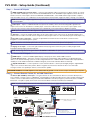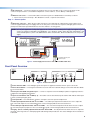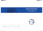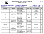
1
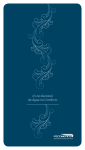
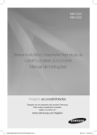
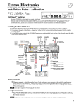
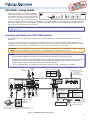
Product Category PVS 405D • Setup Guide The Extron® PVS 405D is a five input, one HDMI output switcher with a built-in audio amplifier and a 3-port Ethernet switch. It is part of the PoleVault®, PlenumVault®, and WallVault® Digital Systems, and is used in conjunction with the Extron PVT digital series of transmitters and Extron speakers. The PVS 405D accepts HDMI and high resolution (RGB) video and audio signals. The RGB input is digitized at the PVT input wallplate. In addition, it has dedicated ports for connecting the optional VoiceLift® system and a Page Sensor unit for facility communications. PVS 405D INPUTS SELECT AUDIO R CONFIG POLEVAULT SWITCHER AUDIO LEVEL ADJUST 1 3 5 2 4 AUX PEAK INPUT VOICELIFT PAGING SENSOR PEAK NORMAL NORMAL SIGNAL SIGNAL SENSITIVITY NOTE: For full installation, configuration, connector wiring, and operation details, see the PVS 405D User Guide, available at www.extron.com. Installing and Cabling the PVS 405D Switcher The PVS 405D may come already pre-mounted in the Extron PMK 560 (Projector Mount Kit) and the PVM 220 (PlenumVault Mount Kit). However, if it is not pre-mounted, to mount the PVS 405D, follow the steps in the system installation guide, supplied with the complete PoleVault, PlenumVault, or WallVault System. Alternatively follow the steps in the relevant Setup Guide for the mounting kit (PMK 560, PVM 220, WMK 160, or USFM 100). Connect the cables to the switcher as shown below. ATTENTION: The PoleVault signal transmission method is specific for PVS 405D switchers working with PVT digital wallplates. DO NOT connect the input ports to an MTP system or to an Ethernet/LAN or data transmission system. NOTES: • The PVS 405D is capable of receiving signals from PVT wallplates located up to 150 feet (45 m) away. • RJ-45 termination must comply with the TIA/EIA T 568A or 568B wiring standards for all connectors. The same standard MUST be used at both ends of all cables. Refer to the PoleVault System Installation Manual for details. The cables supplied with the PoleVault system are terminated to the TIA 568A standard. • The use of shielded cable, such as Extron STP201 or Extron XTP DTP 24 cable, is strongly recommended. Paging Sensor Input Line Out Output (Audio) Audio Output to Speakers Red Black OUTPUT AUDIO OUT L 1/2 3/4 SIG +V HDMI LINK INPUT 5 L PVT IN 6 HDMI/RGB 4 LAN 2 OUT VGA IN RS-232 S G Tx Rx G 10 9 MLC 104 IP Plus RS-232 input MLC wire color To PVS terminal NOTE: You must connect a ground wire between the MLC and PVS. White Violet Drain wire Black Red Tx on RS-232 port Rx on RS-232 port Ground (G) PVS Power Supply (–) PVS Power Supply (+) IR control HDMI Output to Display Device Ground (Gnd) B Receive (Rx) A Transmit (Tx) Transmit (Tx)B Receive (Rx)A B NOTE: If you use cable that has a drain wire, tie the drain wire to ground at both ends. A B MLS PWR RS-232 12V Supplied PVS Switcher External Power Supply (12 VDC, 4 A max.) LAN 3 REMOTE IR SG LAN 1 R AUDIO IN LOCAL OUT S G 3 L Tx AUDIO IN 2 AMPLIFIED AUDIO OUT DO NOT GROUND OR SHORT SPEAKER 4/8 OUTPUTS Ω CLASS 2 WIRING OVER PVT Aux VoiceLift Input Receiver Aux Audio HDMI Connector Input 5 Power Connector HDMI IN VOICELIFT AUX R PVT IN 1 IR OUT PVS 405D Rx 12 PAGING SENSOR +12V IN LINK R 11 8 GROUND SIG Positive (+) Negative (-) GROUND POWER 12V 3A MAX Connect to ports as follows: 1. TCP/IP network 2. MLC controller 3. Optional network device 5 7 INPUTS 3-port 10/100 Ethernet Switch Speaker PVS terminal wire color (left and right) +V Ground +12 VDC input To Supplied PVS Switcher Power Supply (12 VDC, 4 A max.) MLC 104 IP Plus right side panel MLS and Power ports PVT SW HDMI RGB D HDMI or RGB video/audio, Inputs1/2 and 3/4 1 STP cable with RJ-45 connectors Figure 1. PVS 405D Switcher Connections 1 PVS 405D • Setup Guide (Continued) Step 1 — Connect A/V inputs a HDMI and RGB video and audio inputs — Using recommended TP cables (see the Notes re cables on page 1), connect up to four HDMI or RGB input sources via the PVT SW HDMI RGB D or PVT SW HDMI D input wallplates to these two RJ-45 female connectors. These inputs can be four HDMI with embedded audio, or two HDMI and two high resolution computer video and audio sources, or a combination. The front panel input selection button toggles the inputs 1 through 4 as required. NOTE: Each PVT input wallplate supports two input sources. A maximum of two PVT input wallplates can be connected to the PVS 405D. b Audio input — Input 5 is a dedicated-audio only input for an auxiliary, stereo, line-level analog audio signal from an output source such as an iPod device or an MP3 player. Connect the cable from the source to this 5‑pole captive screw connector. The connector can be wired as balanced or unbalanced (see the PVS 405D User Guide for method). NOTE: Input 5 is audio only. No video signals are supported on this input. c Aux input — Connect an auxiliary audio device to this 3-pole captive screw connector. It can be wired for balanced or unbalanced mono audio. Aux audio can be configured to duck program audio or to be mixed with program audio (inputs 1-5). d VoiceLift receiver connection — Connect an optional Extron VoiceLift receiver to this RJ-45 connector for the integration of a VoiceLift Microphone system. NOTE: The Extron VoiceLift Microphone Kit is an optional accessory and must be purchased separately. e Paging sensor input — Connect the optional Extron Priority Page Sensor Kit to this port, to enable program audio interruptions during paging system broadcasts. NOTE: Priority Page Sensor Kits (part numbers 70-1064-01 or 70-619-01) are optional accessories, purchased separately. Step 2 — Connect A/V Outputs f HDMI output — Connect an HDMI capable display or the projector to this female HDMI connector. g Audio Out (line level) — This port is used for connecting an external Extron audio amplifier, a recording podcasting device, or an assistive listening system. It can be configured via RS-232 or USB for fixed or variable audio output (default is variable). It can be wired for balanced or unbalanced signals (see the PVS 405D User Guide for method).. h Amplified Audio Out — Connect speakers to each channel marked “L” and “R” (left and right) using the supplied black 4-pin, 5 mm connector. Wire red to positive, black to negative. Each channel is rated for 25 W at 4 or 8 ohm loads. If using more than one speaker per channel, connect them in parallel. ATTENTION: DO NOT tie L and R outputs to each other and/or to ground as it will short the outputs and damage the amplifier. Step 3 — Connect Remote Control, IR, and LAN Connectors i Remote (RS-232/MLC) control port — The PVS switcher can be controlled via an RS‑232 connection directly from a host computer, a control system, or a MediaLink® Controller (MLC). The MLC provides remote control of input switching and volume. Connect a cable between this port and the MLC MediaLink Controller (see figure 2). The RS-232 protocol is 9600 baud, 8-bit, 1-stop bit, no parity, and no flow control. See the MLC 104 IP Plus User Manual for full details. NOTE: To power the MLC 104 IP Plus wire it directly into the same power supply the switcher uses (see figures 2 and 3). INPUTS OUTPUT AUDIO OUT L 1/2 POWER 12V 3A MAX SIG 3/4 LINK SIG +V HDMI LINK INPUT 5 L PVT IN PAGING SENSOR R PVS 405D AMPLIFIED AUDIO OUT DO NOT GROUND OR SHORT SPEAKER 4/8 OUTPUTS Ω CLASS 2 WIRING VOICELIFT AUX OVER PVT PVT IN Projector R LAN 1 LAN 2 LAN 3 REMOTE IR RS-232 S G Tx Rx G R L RS-232 Ground Rx Tx To Supplied PVS Switcher Power Supply (12 VDC, 4 A max.) IR control IR Out S Ground G Tx Rx IR OUT GROUND RS-232 Transmit (Tx) Tx A Receive (Rx) Receive (Rx) Rx B Transmit (Tx) Ground (Gnd) DISPLAY RS-232/IR G Ground DISPLAY B MLS PWR RS-232 12V A B MLS 2 +12V IN A Tx 3 GROUND 2 DIGITAL I/O Rx 1 Tx CM SCP Rx IR IN A B C D E COMM LINK GROUND MLC 104 IP PLUS GROUND Tx IR OUT DISPLAY RS-232/IR +V OUT GROUND 4 Rx 3 CONFIG +12V IN PC +12 VDC input 2 GROUND VOLUME PRESS TAB WITH TWEEKER TO REMOVE GROUND DVD 1 LAN VCR OFF GROUND ON PWR MLC 104 IP Plus right side panel MLS and Power ports NOTES: • You must connect a ground wire between the MLC and PVS. • If you use cable that has a drain wire, tie the drain wire to ground at both ends. RS-232 12V Figure 2. MLC 104 IP Plus to PVS 405D Connection j IR control port — Connect the wiring from the IR Out port on rear of the MLC to this connector. IR signals on this connector are passed to the connected PVT wallplate for control of devices, such as BluRay or DVD players. k Ethernet connectors — Connect LAN cables to these three ports for 10/100 Ethernet connectivity as follows: 1. TCP/IP network (owner furnished), 2. MLC MediaLink controller, 3. Optional network device Step 4 — Connect power l DC power connector — When all other cables have been connected, plug the cable with the orange captive screw connector (supplied with the power supply) from the 12 VDC power source into this receptacle and apply power. The front panel power LED and an input LED illuminates when the switcher is receiving power. NOTE: Use only the supplied 12 V, 4 A power supply for this switcher. The PVS 405D power supply can support a typical system: for example, a PVS 405D, 2 PVT Wallplates, 2 or 4 speakers, an MLC 104 IP Plus with an IRCM DV+, and a VoiceLift Microphone system. If an additional SCP 104 is used, the MLC 104 IP Plus MUST have its own power supply. SIG 3/4 LINK SIG +V HDMI LINK INPUT 5 L PVT IN PAGING SENSOR PVS 405D AMPLIFIED AUDIO OUT L DO NOT GROUND OR SHORT SPEAKER 4/8 OUTPUTS Ω CLASS 2 WIRING VOICELIFT AUX OVER PVT R PVT IN Included power supply is used for both PVS 405D and MLC 104 IP Plus LAN 1 R LAN 2 LAN 3 REMOTE IR RS-232 S G Tx Rx G A B MLS +12V IN 1/2 POWER 12V 3A MAX R Tx L Rx AUDIO OUT GROUND OUTPUT GROUND INPUTS MLC 104 IP Plus right side panel MLS and Power ports PWR RS-232 12V Figure 3. Power Supply Connections to PVS 405D and MLS 104 IP Plus Front Panel Overview PVS 405D INPUTS SELECT R CONFIG POLEVAULT SWITCHER AUDIO LEVEL ADJUST 1 3 2 4 AUDIO 5 PEAK INPUT AUX VOICELIFT PEAK NORMAL NORMAL SIGNAL SIGNAL PAGING SENSOR SENSITIVITY Heat Shrink Over Drain Wires 1 2 3 4 5 6 7 8 9 10 11 12 Figure 4. Front Panel Features a Power indicator LED — This LED lights green when power is supplied, and amber when in power save mode. b Device Reset button — Pressing this inset button resets the switcher to default settings. See the PVS 405D User Guide for reset mode details. c Front panel mini USB configuration port — Connect a computer to this mini USB port (cable not supplied), for device configuration and upgrading the firmware. d Input selection button and e LEDs (1-5) — The button selects and switches inputs and the LEDs indicate which input is active (current input lights green). f Aux input LED — This LED indicates when the aux input is active for input level adjustment. g Audio input adjustment knobs and h level LEDs — The audio input adjustment knob allows the user to adjust the level of the audio input. The associated LEDs (peak, normal, and signal) indicate the active audio level. i VoiceLift input adjustment knobs and j level LEDs — The VoiceLift level adjustment knob allows the user to adjust the VoiceLift (microphone) input level. The associated LEDs (peak, normal and signal) indicate the active audio level. k Paging Sensor sensitivity adjustment knob and l Status LED — The adjustment knob allows the user to adjust the sensitivity of the Page Sensor to interrupt program audio during facility broadcasts. The status LED lights when a broadcast is detected. 3 PVS 405D • Setup Guide (Continued) Front Panel Operation and Configuring the PVS 405D Switcher For full details of front panel operation and switcher configuration, refer to the PVS 405D User Guide, and the MLC 104 IP Plus User Guide. For VoiceLift and Page Sensor installation and operation details, refer to the VoiceLift System User Guide and the Priority Page Sensor Kit Installation Instructions. All these are available online at www.extron.com. Front Panel Operation 1. 2. 3. To change inputs, press the input button d to sequentially cycle through inputs 1 through 4, (video and audio), and input 5 (audio only). The LEDs e (inputs 1-5) indicate which input is active. The aux input is selectable for configuration only. To do this press and hold the Select button for 3 seconds until the Aux LED lights. To adjust audio input levels, select an input then turn the Input encoder g through 43 positions in 1 dB steps (-18 to +24 dB, default 0). The LEDs h indicate the signal level status (not volume). To adjust VoiceLift microphone level, turn the VoiceLift i through 43 positions in 1 dB steps (-18 to +24 dB, default 0). Front panel LEDs j indicate mic input signal levels. NOTE: On initial switcher power-up the output volume level is automatically adjusted to 80%. 4. To adjust Paging sensitivity, turn the Paging encoder k clockwise to increase, and counter-clockwise to decrease sensitivity. The status LED l illuminates when an announcement from the paging system is detected. The Extron Priority Page Sensor Kits (PPS 35, part number 70-1064-01 or PPS 25, part number 70-619-01) are optional accessories and can be purchased separately. Configuration The PVS 405D switcher can be controlled by a MediaLink Controller (MLC) or by an RS-232 device acting through the MLC. The switcher can be also set up and controlled via a host computer or other device (such as a control system) attached to the rear panel RS-232 remote port of the switcher. The control device (host) can use Extron Simple Instruction Set (SIS™) commands or the Product Configuration Software (PCS) program. See pages 1 and 2 for connection details. NOTE: Configuration can also be completed by connecting a USB cable to the mini USB config. port on the front panel (see c in figure 3). This port uses the same protocol as the rear panel RS-232 port. See the PVS 405D User Guide for full configuration methods using SIS commands. See the Product Configuration Software (PCS) program embedded Help file for configuration methods using PCS. The software and device User Guides and Instructions mentioned in this guide can be found at www.extron.com. Extron Headquarters +1.800.633.9876 (Inside USA/Canada Only) Extron USA - West Extron USA - East +1.714.491.1500+1.919.850.1000 +1.714.491.1517 FAX +1.919.850.1001 FAX Extron Europe +800.3987.6673 (Inside Europe Only) +31.33.453.4040 +31.33.453.4050 FAX Extron Asia +65.6383.4400 +65.6383.4664 FAX Extron Japan +81.3.3511.7655 +81.3.3511.7656 FAX Extron China +86.21.3760.1568 +86.21.3760.1566 FAX Extron Middle East +971.4.299.1800 +971.4.299.1880 FAX © 2014 Extron Electronics All rights reserved. www.extron.com 4 Extron Korea +82.2.3444.1571 +82.2.3444.1575 FAX Extron India 1800.3070.3777 (Inside India Only) +91.80.3055.3777 +91.80.3055.3737 FAX 68-2379-50 Rev. A 01 14