1
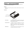
Mobile
Workstation
MW800
Series
ab
Models F5207A, F5217A
User’s Guide
6802976C65-O
@6802976C65@
COMPUTER SOFTWARE COPYRIGHTS
The Motorola products described in this instruction manual may include copyrighted
Motorola computer programs stored in semiconductor memories or other media. Laws in
the United States and other countries preserve for Motorola certain exclusive rights for
copyrighted computer programs, including the exclusive right to copy or reproduce in
any form the copyrighted computer program. Accordingly, any copyrighted Motorola
computer programs contained in the Motorola products described in this instruction
manual may not be copied or reproduced in any manner without the express written
permission of Motorola. Furthermore, the purchase of Motorola products shall not be
deemed to grant either directly or by implication, estoppel or otherwise, any license under
the copyrights, patents or patent applications of Motorola, except for the normal nonexclusive, royalty free license to use that arises by operation of law in the sale of a
product.
COPYRIGHT
Copyright © 2004-2005 Motorola Inc. All rights reserved. No part of this manual may be
transmitted, stored in a retrieval system, or translated into any language or computer
language, in any form or by any means, without the prior written permission of Motorola
Inc.
TRADEMARKS
• Motorola and the Stylized M logo, Private DataTAC, iDEN are registered trademarks
of Motorola Inc.
• Microsoft, Windows and the Windows logo are registered trademarks of Microsoft
Corporation.
• Intel, Pentium are registered trademarks of Intel Corporation.
• The Bluetooth trademarks are owned by their proprietor and used by Motorola, Inc.
under license in the U.S. and other countries.
• Trimble is a registered trademark of Trimble Navigation Limited
• u-Blox is a registered trademark of u-Blox AG.
All other product or service names are the property of their respective owners.
WARRANTY DISCLAIMER
Motorola may add, delete, change, or withdraw, in whole or in part, this document or
software described in this document at any time and without notice. Such document
modifications will be incorporated in new releases of this document on an intermittent
basis. Motorola disclaims any responsibility for labor or material cost involved by
persons outside the company as a result of using this document.
Blank
TABLE OF CONTENTS
Using this Manual
Who Should Use this Manual
Manual Introduction
Related Manuals
On-Line Information
Conventions Used in This Manual
Section 1:
Getting Started..................................................................................................... 1
What is the MW800 Mobile Workstation? ................................................................................................ 1
Getting the MW800 Running .................................................................................................................... 1
Unpacking............................................................................................................................................. 1
Installation and Connecting to Car Battery ........................................................................................... 2
Turning On............................................................................................................................................ 2
Turning Off ........................................................................................................................................... 2
Section 2:
Taking a Look at the MW800 .............................................................................. 3
CPU Box.................................................................................................................................................... 3
Front View ............................................................................................................................................ 3
Rear-Side Components ......................................................................................................................... 4
Bottom-Side Components ..................................................................................................................... 6
Top View .............................................................................................................................................. 6
Display....................................................................................................................................................... 7
Front View ............................................................................................................................................ 7
Bottom-side Components...................................................................................................................... 8
Right-side Components......................................................................................................................... 9
Display Indicators ............................................................................................................................... 10
Keyboard ................................................................................................................................................. 11
Tips ..................................................................................................................................................... 12
Touch pad ........................................................................................................................................... 12
Section 3:
Specifications .................................................................................................... 13
Specifications........................................................................................................................................... 13
Features.................................................................................................................................................... 14
Section 4:
Basic Operations ............................................................................................... 17
Power On ................................................................................................................................................. 17
Normal operation ................................................................................................................................ 17
Extreme Temperature Conditions ....................................................................................................... 17
Discharged Vehicle Battery ................................................................................................................ 18
Power Off ................................................................................................................................................ 18
Normal Operation ............................................................................................................................... 18
Extreme Shut Down ............................................................................................................................ 19
Resetting .................................................................................................................................................. 19
Personal Card........................................................................................................................................... 20
SIM Card ................................................................................................................................................. 20
Volume Control ....................................................................................................................................... 21
Standby .................................................................................................................................................... 21
Section 5:
Installation Tips ................................................................................................. 23
Connection of the MW 800 CPU Box to a Third party Display .............................................................. 23
Connection of MW 800 Display to 3rd Party Personal Computer ............................................................ 23
Tips for F5217A Installation.................................................................................................................... 24
Speed car pulse connection ................................................................................................................. 24
Backward/ Forward connection .......................................................................................................... 24
Section 6:
Maintenance....................................................................................................... 25
Cleaning the Keyboard ............................................................................................................................ 25
Cleaning the Display................................................................................................................................ 25
Section 7:
Getting Assistance from Motorola................................................................... 27
Appendix A: Safety Instructions ............................................................................................ 29
Appendix B: Warranty Information ........................................................................................ 31
Appendix C: FCC Information ................................................................................................ 35
Appendix D: Environmental Specifications .......................................................................... 36
Appendix E: OSD Specifications ........................................................................................... 37
On Screen Display (OSD) Calibration..................................................................................................... 37
OSD Sub-Group Icons ............................................................................................................................. 37
Warning Icons.......................................................................................................................................... 40
Appendix F: Troubleshooting ................................................................................................ 41
Appendix G: Acronyms and Abbreviations .......................................................................... 43
FIGURES AND TABLES
Figure 1. Front View ...................................................................................................................................... 3
Figure 2.F5207A Rear view ........................................................................................................................... 4
Figure 3. F5217A Rear view .......................................................................................................................... 4
Figure 4. Bottom View ................................................................................................................................... 6
Figure 5. Top View......................................................................................................................................... 6
Figure 6. 12.1” Display .................................................................................................................................. 7
Figure 7. 8.4’’ Display................................................................................................................................... 7
Figure 8. 12.1” Display Bottom View ............................................................................................................ 8
Figure 9. 8.4” Display Control Buttons .......................................................................................................... 9
Figure 10. 12.1” Display Control Buttons ...................................................................................................... 9
Figure 11. Keyboad ..................................................................................................................................... 11
Figure 12. Touchpad.................................................................................................................................... 12
Figure 13. Connecting the CPU box to a 3rd Party Display ......................................................................... 23
Figure 14. Connecting the Display box to a PC .......................................................................................... 23
Figure 15. Main OSD Menu ......................................................................................................................... 37
Figure 16. OSD Sub-Group Icons. ............................................................................................................... 38
Figure 17. Connection Warning ................................................................................................................... 40
Figure 18. Mode Error Warning ................................................................................................................... 40
Figure 19. Refresh Rate Warning ................................................................................................................. 40
Table 1. MW800 error messages.................................................................................................................. 41
Table 2. Indications about failure condition ................................................................................................. 42
Table 3. MW800 failures without user notification...................................................................................... 42
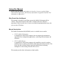
Using this Manual
Before using this manual and products it describes, be sure to read the Safety
instructions in Appendix A, the Warranty information in Appendix B and the FCC
information in Appendix C.
Who Should Use this Manual
This manual is intended for staff that operates the Mobile Workstation 800 in
vehicles. This manual assumes that reader is familiar with basic Windows
operations. If this is not the case, be sure to read the documentation that came with
your version of Windows.
Manual Introduction
The Mobile Workstation 800 (MW800) series is available in two models:
•
F5207- Mobile Workstation
A multipurpose mobile data computer, that can support the simultaneous
operation of two independent applications, each using different display and
keyboard.
•
F5217- Mobile Router
A multipurpose mobile data computer with capability to provide seamless
mobility across a number of dissimilar public and private data networks. This
device has three distinct Ethernet ports and adds the dead reckoning
intelligence to data coming from the GPS receiver.
This manual provides basic information on both models.
This manual is organized as follows:
•
•
•
•
•
•
•
Section 1 provides general information
Section 2 identifies mobile workstation components
Section 3 provides product specifications
Section 4 provides a description of basic operations
Section 5 describes installation tips
Section 6 describes storage and maintenance rules
Section 7 describes how to get assistance from Motorola
The Appendixes contain:
•
•
•
•
•
•
•
Appendix A:
Appendix B:
Appendix C:
Appendix D:
Appendix E:
Appendix E:
Appendix F:
Safety instructions
Warranty information
FCC information
Environmental specifications
On-Screen Display
Troubleshooting
Acronyms and Abbreviations
Related Manuals
This manual describes the MW800 and provides basic knowledge about the device.
Please note that although this manual refers to hardware and software components
supplied with the MW800, it does not provide full component descriptions. For
additional information refer to the following manuals:
•
•
•
Mobile Workstation 800 Series, Owner’s Manual for CPU
- 6802976C60
Mobile Workstation 800 Series, Owner’s Manual for Display - 6802976C75
Mobile Workstation 800 Series, Installation Manual
- 6802967C20
For documentation of software applications supplied with this product, refer to the
help file attached to each application. This manual is designed to supplement the online or context-sensitive help installed with each software component. Please review
this information to ensure proper use of the product.
On-Line Information
For your convenience, the Motorola website provides up-to-date information about
MW800 products. The URL address for the MW800 home page is
http://www.motorola.com.
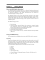
Conventions Used in This Manual
Throughout this publication, you will notice the use of WARNING and CAUTION
marks. These notations are used to emphasize that safety hazards exist, and care must
be taken. Do not proceed beyond a WARNING or CAUTION until the indicated
conditions are fully understood and met.
The following conventions are used throughout this manual:
Italics
Bold
Program ->
Motorola ->
MW800 CPU->
CPU Manager
NOTE:
CAUTION:
WARNING:
Used for emphasis and for new terms.
Used to indicate keyboard keys or application buttons.
Used to designate the location and name of a menu
function. For example, Program -> Motorola -> MW800
CPU-> CPU Manager launch CPU Manager program.
Indicates an operational procedure, practice, or condition to
which you should pay special attention.
Alerts you of conditions, which can result in loss or
corruption of data, or damage to device.
Indicates a potentially hazardous situation, which, if not
avoided, may result in injury. It may also be used to alert
against unsafe practices and property-damage-only
accident hazards.
Blank
1
Section 1:
Getting Started
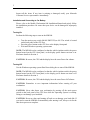
What is the MW800 Mobile Workstation?
The Motorola Mobile Workstation 800 series is Motorola's highest-performing and
most rugged data communication and computing solution. It is specifically designed
for the harsh conditions of the mobile environment-areas not suitable for
conventional laptop or desktop computers.
The MW800 consists of three separate interconnected components: CPU, Display
and Keyboard and can be mounted in dual airbag-equipped vehicles. Using customdesigned cable adapters, the CPU can be connected to the MW800 displays or any
3rd-party LCD, CRT or Flat Screen display. Each component can also be used as a
standalone product.
The MW800 design provides:
•
•
•
•
•
Sealed housing
Protection against extremely high and low temperatures: automatic heating
when temperature drops below freezing point; automatic heat reducing
measures when temperature exceeds high operational limit
Protection against extreme shock and vibration
Withstanding cranking conditions
Easy access to Personal Card (PC) and Radio Subscriber Identity Module
(SIM) card
Getting the MW800 Running
This section guides you through procedures to get the MW800 ready for operation.
Unpacking
Unpack your shipment and check the contents to ensure that you have received all
the specified items. Save the packing carton and anti-static plastic bag for storage
and shipping. Both the shipping carton and the anti-static bags protect the MW800
components from physical and electrostatic damage.
After unpacking the shipping carton, the following items should be found:
•
•
•
•
•
•
•
CPU box
Display
Keyboard
Power cord
CPU-to-Display cable
CD with Windows XP Operating System or Windows 2000 Recovery kit
This User’s Guide
2
Inspect all the items. If any item is missing or damaged, notify your Motorola
Customer Service representative immediately.
Installation and Connecting to Car Battery
Please, refer to the Mobile Workstation 800 Installation Manual and strictly follow
the installation procedure. Be aware that your device can be damaged if improperly
installed.
Turning On
Perform the following steps to turn on the MW800.
•
•
•
Turn the main power switch (MAIN SWITCH) to ON. The switch is located
on the back panel of the CPU box
Press the power button on the CPU box or the display front panel
Wait until Windows operating system starts
NOTE: The MW800 can be configured so that the vehicle ignition switch, the power
button located on the CPU front panel, or the display power button can turn it on.
Find more details in Section 4.
CAUTION: Be aware, the CPU and the display have the same Power On scheme.
Turning Off
Use the Windows operating system Shut Down dialog box to turn off the MW800.
NOTE: The MW800 can be configured so that the vehicle ignition switch, the power
button located on the CPU front panel, or the display power button can turn it off.
Find more details in Section 4.
CAUTION: Be aware, the CPU and the display have the same Power Off scheme.
CAUTION: Remember to save important information before turning off your
workstation.
CAUTION: Never shut down your workstation by turning off the main power
switch on the back panel of the CPU box while the Operating System is working.
Doing so can damage your hard disk.
CAUTION: Be aware, that rapid turning off and on can damage your hard disk. If
you need to turn the MW800 on immediately after turning it off, always wait for the
shut down process to complete.
3
Section 2:
Taking a Look at the MW800
This chapter identifies the external components of each part of the MW800 and
provides a brief functional description.
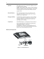
CPU Box
The front side of the CPU box allows user interface with Power button, PC and radio
SIM cards.
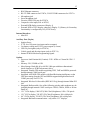
Front View
Power Button
PC & SIM Card Slots
Figure 1. Front View
Power Button
Turns the MW800 power ON and OFF. Note that the main
power switch on the rear CPU panel must be switched on
before using the Power button.
Personal Card slot
A Personal Card (PC) slot enhances the CPU box
performances by enabling the connection of a variety of
personal cards that can be used as storage devices,
modems, etc. The card slot is completely sealed when the
cover is closed.
SIM Card slot
Accepts the SIM card of the internal WWAN radio. The
slot is fully sealed when the cover is closed.
4
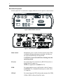
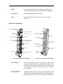
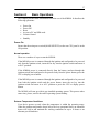
Rear-Side Components
F5207A and F5217A models have slightly different rear-side panels as shown below:
MAIN SWITCH
W-
PWR
GPS
LAN
MIC
SERIAL
AUX
IN
W-WAN
13.8V
AUDIO OUT
VIDEO IN
DISPLAY 1
USB
USB
DISPLAY 2
LAN
FIREWIRE
Figure 2. Model F5207A - Rear View
Figure 3. Model F5217A - Rear View
Main Switch
Maintenance power switch. Use this switch to turn off the
workstation during maintenance operations. In daily use,
the switch should be kept in ON position.
CAUTION: do not switch off before shutting down the
operating system.
Firewire
For connecting a Firewire® device (IEEE1394) such as a
digital camera, scanner, etc.
NOTE: not applicable for model F5217A.
PWR
For connecting the power cord from the vehicle’s battery.
CAUTION: Use a standard Motorola power cable with a
15-Amp fuse.
WWAN
For connecting mini-UHF radio modem antenna for GPRS,
CDMA, iDEN or Private DataTAC radio.
5
Mic In
External input jack for Mono microphone for sound
recording.
Audio Out
For connecting headphones, external speakers with power
amplifier or audio recording device.
Display 1
Connects the CPU to the Display. Carries RGB, USB and
audio to the screen.
Display 2
Connects the CPU to the Display. Carries DVI for flat
screen interface. Also carries RGB, USB and audio to the
screen with additional cable adapters (optional).
NOTE: not applicable for model F5217A.
LAN
For connecting the LAN cable. Includes a Link and Active
indicators.
Serial 1
For connecting a serial device such as Motorola’s VRM
modems, printer, mouse, etc. The connection requires a
COTS (Commercial Off-The-Shelf) cable (not supplied).
Serial 2
Additional serial connection in model F5217A only.
AUX
Connects vehicle ignition switch, General Purpose I/Os (2
In, 2 OUT), additional USB port, internal modem
programming signals as well as 5VDC and car battery
voltage outputs.
NOTE: model F5217A provides vehicle speed and
direction inputs and does not provide additional USB port.
Video In
Composite Video input for connecting external VCR or
video camera.
GPS
Connects GPS antenna to the internal GPS receiver
(optional).
USB
Each port connects a USB 2.0 or USB 1.1 device.
WLAN
Connects RF antenna (SMA) to the (optional) internal
WLAN radio (802.11b/g)
6
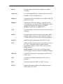
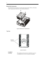
Bottom-Side Components
The Hard Disk Compartment is located at the bottom of the CPU box. The Hard
Disk Compartment contains the removable hard disk drive.
Figure 4. Bottom View – Hard Disk Drive
Top View
Ventilation
Openings
Figure 5. Top View
Ventilation
Openings
The openings ensure proper air circulation to prevent
overheating. Never cover or block these openings.
7
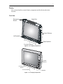
Display
This section identifies external display components and briefly describes their
function.
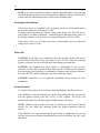
Front View
Hand Grip
Emergency
Button
Control Buttons
Left Speaker
F1
Right Speaker
Function Buttons
F8
Figure 6. 12.1” Display Components
Control
Buttons
Emergency
Button
F1
Function Buttons
F6
Figure 7. 8.4’’ Display Components
Speaker
8
Speakers
The speakers (two in 12.1”, one in 8.4” display) are used
for audio and alert signaling.
NOTE: Adjust speaker volume with the Volume Up/Down
buttons or with the Volume Control program. The Volume
Control program can be found on the Windows task bar
(speaker icon).
Function Buttons
The 8 Function buttons (6 for 8.4”) facilitate specific
operations. The function of each button is set via a preinstalled software application
Emergency Button
Use this button to signal an emergency event to software
emergency application, installed in the workstation. The
Emergency button becomes functional as soon as the
operating system is running.
Touch Panel
The MW800 display is sealed against moisture and has a
dirt resistant touch panel, which can be activated with
either a gloved finger or a stylus pen.
CAUTION: Re-calibration is required when you see a
discrepancy between the touched and displayed positions.
Refer to your system administrator for help.
Bottom-side Components
USB Port 1
Display Power
Cable
CPU-Display USB Port 2
Signal Cable
Figure 8. 12.1” Display Bottom View
9
PWR
For connecting the power cord from the vehicle battery.
Use a standard Motorola power cable with a 15-Amp fuse.
CPU Cable
Connects the display to the CPU box.
USB
Each port connects a USB 1.1 device such a keyboard,
mouse, etc.
Right-side Components
Workstation Power
Indicator
Workstation Power Button
Temperature
Indicator
Suspend Indicator
Screen Back-light
Indicator
Communication Indicator
Workstation Power
Button / Indicator
Temperature
Indicator
Suspend Mode
Communication
Indicator
Screen Back-light On/Off &
Buttons illumination Level
Brightness up/down
Suspend Mode
Button / Indicator
Backlight On / Off &
Indication Intensity
Control
Button / Indicator
Brightness & Volume
up / down Control
Volume up/down
RGB Indicator
On Screen Display (OSD)
Menu
Figure 9. 8.4” Display Control Buttons
On Screen Display
(OSD) Button /
Indicator
Figure 10. 12.1” Display Control Buttons
Power Button
Turns the MW800 power ON and OFF. This button
functions identically as the Power Button on the front panel
of the CPU box. Be aware, the main power switch on the
rear CPU panel, must be switched on before using the
Power Button.
Standby Button
Use this button to go into a low power consumption state
(Standby mode). In Standby mode, the workstation enters a
power-saving mode, turns off the display backlight and
10
slows down the processor speed. The workstation radios
remain powered on.
Backlight Button
Brightness Up/Down
Buttons
Volume Up/Down
Buttons
OSD Menu Button
Turns the LCD backlight ON and OFF; provides five levels
of illumination to the display buttons and indicators.
Increases (the upper button) or decreases (the lower button)
a level of the screen brightness. You can set up to 64
continuous brightness levels. Press firmly for fast
brightness level adjustment.
Increases (the upper button) or decreases (the lower button)
the level of speaker volume. You can tap up to 64
continuous volume levels. To mute the sound, hold down
the Up and Down buttons together for at least one second.
Press firmly for fast volume level increase/decrease.
NOTE: these buttons also serve as navigation buttons for
the OSD
The OSD menu button is used to pop-up the OSD menu
and adjusts the display’s appearance and performance. For
details see Appendix E.
Display Indicators
Power
For 13.8VDC battery:
Steady green: Workstation is on and vehicle power is OK;
Blinks yellow: Vehicle battery is low (10.2 VDC) during
workstation operation;
Steady yellow: Vehicle battery is low (9.4 to 10.3 VDC)
during workstation power up.
For 9VDC battery:
Steady green: Workstation is on and vehicle power is OK;
Steady yellow: Vehicle battery is low (less than 9VDC).
Temperature
Off: Normal Operation
Blinks red: Display temperature is extremely high during
power on.
Blinks yellow: Display temperature is extremely low during
operation.
11
Communication
Off: Normal operation
Steady blue: CPU box to display USB power problem, or
display in programming mode. Check cable connection
Steady yellow: CPU box fails to communicate with the
display.
Steady purple: CPU box to display USB power and
communication problem.
Standby
Off: Normal operation.
Steady green: Workstation is in Standby mode.
Backlight
Off: LCD backlight is on.
Steady blue: LCD backlight is off.
Link
Steady green: Valid input signal from the CPU box.
Steady yellow & green: NO valid input signal from the
CPU box.
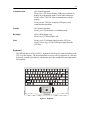
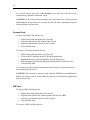
Keyboard
The MW800 has an 85-key USB 1.1 keyboard, which can be connected either to the
CPU or to the display. The keyboard allows access to all key functions of a full size
keyboard; a touch pad with two side-buttons provides standard left and right mouse
functionality.
End
F1
~
Tab
Caps
Lock
F3
F2
@
2
!
1
Q
W
A
Ctrl
#
3
E
S
Z
F5
F4
%
5
6
R
T
Y
F
C
G
V
F8
F7
$
4
D
X
F6
&
7
N
1
M
(
9
8
I
4
J
H
B
8
7
U
F9
0
>
,
.
Ins
A
B
Figure 11. Keyboard
.
F12
Num
Lock
+
=
Back Space
{
[
-
:
;
3
<
Alt
_
P
6
L
2
F11
)
0
9
O
5
K
F10
"
'
+
?
/
Del
}
]
Prt Scr
|
\
Pause
PgUp
Enter
Shift
/
Fn
Esc
12
Tips
•
•
•
To change illumination level of the keyboard backlight, press the Fn key and
tap on the left or right arrow keys. The level of illumination will change
repeatedly from off to maximum in seven steps.
The keyboard incorporates a power saving feature that automatically turns off
the keyboard backlighting after a keyboard illumination time-out is expired.
Striking any key restores backlighting.
To set duration of the keyboard illumination, press the Fn key and tap on the
arrow up or down keys. The up and down arrow keys will repeatedly
increase/decrease the period of illumination in seven steps of 10 minutes
(maximum of 70 minutes).
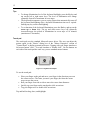
Touch pad
The touch pad uses the standard Microsoft mouse driver. The user can adjust the
pointer speed in the "Basics" dialog box of the "Mouse Properties" section of
"Control Panel" to his/her personal preference. Tapping with your finger simulates a
left mouse button "click". Two taps simulates a "double click". Use the buttons on
each side of the touch pad the same way you use standard mouse buttons.
A
B
Figure 12. Keyboard Touchpad
To use the touch pad:
•
•
•
•
Place your finger on the pad and move your finger in the direction you want
the cursor to move. The faster you move your finger, the faster the cursor
moves across the screen.
Roll your finger from side to side to move the cursor short distances.
Quickly tap your finger on the touch pad to click on an item.
Tap your finger twice to double-click on an item.
Tap and hold to drag, draw, and highlight.
13
Section 3:
Specifications
Specifications
Size
• CPU:
Width: 7.75” (19.7 cm); Depth: 9.45” (24.0 cm); Height: 2.74” (6.95 cm)
• 12.1” Display:
Width: 12.2” (31 cm); Depth: 10.6” (26.9 cm); Height: 2.2” (5.6 cm)
• 8.4” Display:
Width: 9.1” (23.1 cm); Depth: 7.1” (18.1 cm); Height: 1.69” (4.3 cm)
• Keyboard:
Width: 7.75” (19.7 cm); Depth: 9.45” (24.0 cm); Height: 2.74”
Weight
• CPU:
• 12.1” Display:
• 8.4” Display:
• Keyboard:
7.7 pounds (3.5 kg)
8.4 pounds (3.8 kg)
3.3 pounds (1.5 kg)
2.2 pounds (1.0 kg)
Power source
• Vehicle battery, negative ground.
• Voltage Input Variation13.8 VDC ± 20% with no loss of functionality.
• Power loss compensation during engine cranking in standard 13.8 VDC
battery system.
• Current consumption at 13.8 VDC:
! Maximal
5A
! Typical
3.5A (CPU - 1.5A, Display – 2A)
! Standby
0.4 A
! Power off
0.05 A.
• Capability to support 9 VDC vehicle battery.
• Vehicle ignition switch sensing.
• Electrical Transients meet ISO7637-1 standard.
• Car battery voltage (1A maximum) and 5 VDC (1A maximum) power outputs
to peripherals from AUX port. Voltage level at 12VDC output is equal to car
battery voltage input.
Environment
• Storage temperature:
• Operating temperature:
• Humidity:
-40° to 158° F (-40° to +70° C)
-22° to 158° F (-30° to +70° C)
90 to 95% Relative humidity at 50° C for 8 hours
Refer to Appendix E for detailed Environmental specifications.
14
Features
Operating System:
• Windows XP Pro or Windows 2000.
Basic Processor (other options available):
• Intel Pentium M (Centrino) #715 1.5 GHz processor.
Memory (other options available):
• Double data rate (DDR) synchronous expandable dynamic random access
memory (DRAM) 256 MB.
Mass Storage (other options available):
• Hard disk 40 GB, 5400 rpm with three-dimensional shock absorbers.
Keyboard
• 85-key USB keyboard. English only or dual language keyboards are available.
• Access to all the key functions of a full size keyboard
• Touch pad and right and left mouse buttons.
• Backlight control with seven illumination levels
• Backlight duration control
Display
• Two sizes (12.1” and 8.4”), three models (12.1” XGA high brightness&
SVGA standard brightness, 8.4” SVGA standard brightness)
• Color display using TFT technology
• Tempered glass covered by a protective film
• Internal heater, backlight operation in low temperatures.
• LED indicators for alarm reports and workstation status.
• Two speakers on the front of the display panel (one speaker in 8.4” model)
• Two USB 1.1 connectors (second USB port is optional in 8.4”)
• 8 function buttons (6 in 8.4”)
• Volume, brightness, standby and backlight control buttons
• On-Screen Display
• Emergency button
• Workstation power button
Video controller
• Integrated 2D or 3D graphic and multimedia accelerator.
• 32MB Internal CACHE memory
External CPU Interfaces
• 2 USB 2.0 connectors for F5207A, 3 USB 2.0 connectors for F5217A
• PC card slot (Type II)
• SIM card slot
15
•
•
•
•
•
•
•
•
RJ45 Ethernet connector
RS-232 DB9 connector for F5207A, 2 RS-232 DB9 connectors for F5217A
Microphone jack
Stereo headphone jack
Firewire (IEEE1394) port for F5207A
Composite video input (PAL or NTSC)
External RGB display connectors (Display 1)
External RGB or DVI display connector (Display 2) (Primary & Secondary
functionality is configured by OS), F5207A only.
Internal Interfaces
• Mini-PCI
Auxiliary Port (26-pin)
• Ignition Sense
• 4 TTL level I/O ports (two inputs and two outputs)
• Car battery voltage and 5 VDC power outputs (1A max)
• USB 2.0 port signals (only in F5207A)
• Vehicle speed and direction inputs (only in F5217A)
• Internal WWAN Modem Programming signals
Options
• Processor: Intel Pentium M (Centrino) #745 1.8GHz or Celeron M #320 1.3
GHz.
• Memory: 256, 512MB or 1GB.
• Mass Storage: Hard disk 40 or 60 GB, 5400 rpm with three-dimensional
shock absorbers or 2GB Flash memory drive.
• Integrated Trimble GPS module supporting TSIP, TAIP and NMEA protocols
through internal COM2 serial port.
• Integrated ANTARIS GPS module with Dead-Reckoning intelligence on the
GPS data coming from the GPS and NMEA support through internal serial
COM2 port (only for F5217A).
• Integrated Wireless LAN module (IEEE 802.11b/g) through internal Mini-PCI
slot.
• Integrated Radio module. One of the following wireless radio modems may be
installed through internal COM3 serial port: GPRS, CDMA, iDEN or Private
DataTAC.
• 12.1” XGA display, 1200 NIT (1200 Cd/m2) brightness, 1024 x 768 pixels.
• 12.1” SVGA display, 350 NIT (350 Cd/m2) brightness, 800 x 600 pixels.
• 8.4” SVGA display, 350 NIT (350 Cd/m2) brightness, 800 x 600 pixels.
• Integrated Bluetooth communication - only on the 12.1” displays.
16
Blank
17
Section 4:
Basic Operations
This chapter provides basic information about the use of the MW800. It describes the
following operations:
•
•
•
•
•
•
Power On
Power Off
Reset
Access to PC and SIM cards
Volume Control
Standby
Power On
Ensure that the main power switch (MAIN SWITCH) on the rear CPU panel is in the
ON position.
Normal operation
There are a number of ways to start the MW800.
If the MW800 power is connected through the ignition and configured to be powered
only from the ignition switch, insert the car key into the ignition switch and rotate it
to ACC position.
If the MW800 power is connected directly from the battery (and not through the
ignition switch) and configured to be powered only from the power button, press the
CPU or display power button.
If the MW800 power is connected through the ignition and configured to be powered
from both the ignition switch and the power button, insert the car key into the
ignition switch and rotate it to ACC position or press the CPU or display power
button.
The MW800 will start up with its pre-installed operating system. This process takes
some time; please, wait for the end of operating system loading.
Extreme Temperature Conditions
Your device powers up only when the temperature is within the operating range.
When the ambient temperature drops below the low operational limit, an automatic
heater will kick in and maintain the working conditions for up to 16 hours or an
alternate pre-defined time.
18
NOTE: Your device performance might be slightly degraded (both boot up time and
sustained operations) during extreme temperature conditions. Normal operation will
resume when the ambient temperature returns to the operating range.
Discharged Vehicle Battery
If the power source is a standard 13.8V car battery, the device will normally power
up when the voltage level exceeds 10.3 VDC.
If, during normal operation, the battery voltage drops below 10.3 VDC the device
will provide Low Battery indication - workstation power indicator blinks yellow. If
the voltage continues to drop, the device automatically powers off at 8.5 VDC.
If the power source is a 9V battery, the device will normally power up when the
voltage level exceeds 9 VDC.
Power Off
CAUTION: Never shut your workstation down by turning off the main power
switch (MAIN SWITCH) on the back panel of the CPU box while the Operating
System is working. Be aware, this operation may damage your hard disk.
CAUTION: The MW800 shut down scheme is configurable to one of three
selections: via the vehicle ignition switch, from the CPU or Display power button or
from the display power button or a combination of ignition sense and power buttons.
Be aware, the CPU and the display have the same shut down scheme.
CAUTION: Remember to save important information before turning off your
workstation.
Normal Operation
You should always shut your device down from the Windows Shut Down process.
If the MW800 is connected through the ignition and configured to be powered off
from the ignition switch, rotate the car key to OFF position. The device will
automatically shut down when the Ignition shutdown time-out expires.
NOTE: Windows pop-up dialog will warn you about power off from the ignition
switch. You can cancel this operation before the Ignition shutdown time-out
expires.
If the MW800 is not connected through the ignition but is configured to be powered
off only from the power button, momentarily press the Power button. The device will
shut down.
19
CAUTION: If the system does not respond, you can turn the device off by pressing
and holding the power button for 6 seconds or more. Be aware, this hardware power
off may damage your hard disk.
Extreme Shut Down
Some extreme events may cause your device to power off. If any of these events
occurs, you will be warned about it and asked to immediately save your work. The
events are:
•
Internal temperature drops below the low operational limit.
If during operation the ambient temperature exceeds the operating temperature
range or internal temperature drops below the low operational limit for any
reason, the CPU processor eventually powers off. A message ”CPU
temperature is low. The system will shutdown in 3 minutes. Please save
your work” will warn you about this event.
CAUTION: If extremely low temperature is the reason for shut down, never
turn on the device until it warms up to normal operating temperature as
indicated by the temperature LED on the front panel of the MW800 display.
•
Internal temperature exceeds the high operational limit.
If during operation the ambient temperature exceeds the operating temperature
range or internal temperature exceeds the high operational limit for of any
reason, the CPU processor gradually slows down, and eventually powers off.
A message ”CPU temperature is high. The system will shutdown in 3
minutes. Please save your work” will warn you about this event.
CAUTION: If overheating is the reason for shut down, never turn on the
device until it cools down to normal operating temperature.
•
Vehicle battery is discharged
A message ”Vehicle Battery is Low. The system will shutdown in 3
minutes. Please save your work” will warn you about this event.
•
Battery voltage drops below the 8.8V limit for 20 seconds or more.
The device will execute critical shut off and power itself off.
Resetting
You may have to reset the MW800 if an error occurs and the program you are using
locks up. Be aware that the system may have been processing data when it locked up.
If you are sure the system operation has stopped and you cannot use the ‘Restart’
function of the operating system, reset your device. Be aware that resetting will
cause unsaved data to be lost.
20
To reset the device, press the <Ctrl+Alt+Del> keys, and select the Shut Down
option from the Windows shut down screen.
CAUTION: If the system does not respond, you can turn the device off by pressing
and holding the power button for 6 seconds or more. Be aware, this hardware power
off may damage your hard disk.
Personal Card
To insert a Personal Card into the slot:
•
•
•
•
Pull the door latch and open the PC slot door.
Align the card with the slot with the label side up
Insert the card into the slot until it locks in place.
Close the door latch
To remove a Personal Card from the slot:
•
•
•
•
•
Pull the door latch and open the PC slot door.
Click on the PC indicator on the PC Windows application.
Highlight the name of the card and then click the Stop button.
When prompted, press the Eject Button and pullout the card from the slot.
Close the door latch
If you want to use the card again immediately after ejecting it, pull it out about one
inch and then push it back in.
CAUTION: Do not insert or remove a card when the MW800 is in standby mode.
Before you insert or remove a card, make sure that you exit all software applications
that access the card.
SIM Card
To insert a SIM card into the slot:
•
•
•
•
Pull the door latch and open the PC slot door.
Align the card with the slot with the golden SIM side up (TBD)
Insert the card into the slot until it locks in place.
Close the door latch
To remove a SIM Card from the slot:
21
•
•
Pull the door latch and open the PC slot door.
Push the button and pullout the card from the slot.
CAUTION: Inserting/removing SIM card when MW800 is running can corrupt SIM
card information. Please, insert/remove SIM card when MW800 is off.
Volume Control
Adjust the speaker volume with the Volume Up/Down buttons or with the Volume
Control program. The Volume Control program can be found on the Windows task
bar (speaker icon).
When using the Volume Control program note that the “Audio Out” outlet, on the
back panel of the CPU box, is referred to as “Headphones”
The display speakers are referred to as “Volume Control” For example, to assign the
volume control bar to the “Audio Out” outlet, on the back side of CPU box, perform
the following:
•
•
•
Click on the speaker icon on the Windows task bar.
Click on Options and select Properties.
From the Options dialog box, check the Others option and select Headphones
from the drop menu.
NOTE: if your display unit includes a Bluetooth component, this application also
allows commutation of audio stream to the Bluetooth device.
Standby
To enter low-power state (standby), press the Standby button on the right display
side. In standby, the MW800 enters a power-saving mode, turns off the display
backlight and slows down the workstation speed. The workstation radios remain
powered on. To resume normal operation again, touch the display panel or press any
display function key.
22
Blank
23
Section 5:
Installation Tips
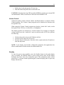
Connection of the MW 800 CPU Box to a Third party Display
An optional cable adapter (FKN8144) enables you to interface the MW 800 CPU
box with most 3rd party displays. The cable adapter connects to the standard CPUDisplay signal cable. The cable adapter is shown in the figure below.
Standard Display
RGB Connector
MW 800 CPU Box
CPU-Display Signal Cable
Cable Adaptor
USB Connector (female type)
Figure 13. Connecting the CPU box to a 3rd Party Display
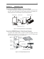
Connection of MW 800 Display to 3rd Party Personal Computer
An optional cable adaptor enables to interface the MW 800 display with most
standard personal computers. The cable adapter connects to the CPU-Display signal
cable. The cable adaptor is shown in the figure below.
Standard
PC
USB
Connector
(male type)
Speaker
Jack
Microphone Jack
MW 800
Display
RGB Connector
Cable Adaptor
CPU-Display Signal Cable
Figure 14. Connecting the Display box to a PC
24
Tips for F5217A Installation
•
Use the AUX 26 pin cable Motorola p/n 3087563V93 for interface to the vehicle
to access to vehicle speed and direction outputs.
Reading the vehicle speed signals
•
•
Connect the “+” terminal of the vehicle speed signals to the AUX port pin1 (black
wire).
Connect the “-” terminal of the vehicle speed signals to the AUX port pin2
(brown wire).
Reading the Forward /Backward drive direction signals
•
•
•
Connect the “+” terminal of the vehicle forward/backward drive direction signals
to the AUX port pin 3 (red wire).
Connect the “-” terminal of the vehicle forward/backward signals to the AUX port
pin 4 (orange wire).
If the vehicle forward/backward signals connection is not utilized, connect AUX
port pin 3 (red wire) to the 5VDC and AUX port pin 4 (orange wire) to the GND.
NOTE: 5VDC signal is available on AUX port pin 25 (blue wire 24 AWG), GND
signal is available on AUX port pin 11 (gray wire 28 AWG)
25
Section 6:
Maintenance
Cleaning the Keyboard
•
•
•
Spray some ethyl or rubbing (isopropyl) alcohol on a dry soft cloth.
Wipe the keyboard surface with the cloth.
Let the keyboard dry for few minutes.
If the keyboard is very dirty and sticky as a result of a liquid spill, contact a service
technician.
CAUTION: avoid spraying cleaner directly on the keyboard; always ensure that no
liquid drips on the keyboard.
Cleaning the Display
•
•
•
Wipe the display with a dry soft cloth.
If your display has stains, spray some ethyl or rubbing (isopropyl) alcohol on a
dry soft cloth and wipe the display surface.
Let the display dry for few minutes.
If the display is very dirty, contact a service technician.
CAUTION: Do not use water, window cleaner, acetone, aromatic solvent or dry, rough
towels to clean the screen.
26
Blank
27
Section 7:
Getting Assistance from Motorola
For your convenience, the Motorola website provides up-to-date information about
the MW800.
The URL address for the MW800 home page is http://www.motorola.com.
This site includes general information about the device, as well as answers to
questions regarding operational issues with the MW800. The site also provides the
following:
•
•
•
•
Recent software / application updates
Updated embedded firmware for your computer
The latest device drivers
Frequently Asked Questions (FAQ)
28
Blank
29
Appendix A: Safety Instructions
WARNING:
Reduce the risk of fire or electric shock by following basic safety instructions:
• Do not connect or disconnect cables while you device is turned on.
• Protect your device from liquids. Keep your device away from water.
• Do not use any power cord where input or output pins show signs of corrosion
or overheating.
• Be sure that all power cord connections are securely plugged into receptacles.
• Never coil a power cord.
• Always route a power cord and communication cables so they will not be
damaged.
CAUTION:
Your device generates heat when turned on. Never block or cover ventilation slots
and fans.
CAUTION:
The device is very sensitive to uncontrolled shut down. Never turn off the device by
turning off the power supply or by disconnection of the power cable.
CAUTION:
The CMOS battery can degrade if your device is unused for more than 3 months.
Leaving a battery in a discharged state could shorten a lifetime of the battery.
CAUTION:
Hard drive performance and lifetime could be shortened if your device is not used
for long periods of time. Do not leave the device unused for more than 3 months.
CAUTION:
Your device automatically shuts down when the internal temperature exceeds the
high limit of the valid range. The device will operate when it cools down.
CAUTION:
Your device dissipates heat during normal operation. When your device is
functioning, do not allow it to contact any part of your body for an extended period
of time – it could cause discomfort.
CAUTION:
Avoid inserting any card or device into computer slots at an angle – it could damage
connectors in your device.
30
CAUTION:
Normally, if the system does not respond, you can turn the device off by pressing
and holding the power button for 6 seconds or more. Be aware, this method of
hardware power off may damage your hard disk.
CAUTION:
Do not insert or remove card when the MW800 is in Suspend mode. Before you
insert or remove a card, make sure that you exit all software applications that access
the card.
31
Appendix B: Warranty Information
EPS – 34440- B
This warranty applies within the fifty (50) United States, the District of Columbia and
Canada.
LIMITED WARRANTY
MOTOROLA COMMUNICATION PRODUCTS
If the affected product is being purchased pursuant to a written Communications System
Agreement signed by Motorola, the warranty contained in that written agreement will
apply. Otherwise, the following warranty applies.
I. WHAT THIS WARRANTY COVERS AND FOR HOW LONG:
Motorola Inc. or, if applicable, Motorola Canada Limited ("Motorola") warrants the
Motorola manufactured radio communications product, including original equipment
crystal devices and channel elements ("Product"), against material defects in material and
workmanship under normal use and service for a period of One (1) Year from the date of
shipment. Motorola, at its option, will at no charge either repair the Product (with new or
reconditioned parts), replace it with the same or equivalent Product (using new or
reconditioned Product), or refund the purchase price of the Product during the warranty
period provided purchaser notifies Motorola according to the terms of this warranty.
Repaired or replaced Product is warranted for the balance of the original applicable
warranty period. All replaced parts of the Product shall become the property of Motorola.
This express limited warranty is extended by Motorola to the original end user purchaser
purchasing the Product for purposes of leasing or for commercial, industrial, or
governmental use only, and is not assignable or transferable to any other party. This is the
complete warranty for the Product manufactured by Motorola. Motorola assumes no
obligations or liability for additions or modifications to this warranty unless made in
writing and signed by an officer of Motorola.
Unless made in a separate written agreement between Motorola and the original end user
purchaser, Motorola does not warrant the installation, maintenance or service of the
Product. Motorola cannot be responsible in any way for any ancillary equipment not
furnished by Motorola, which is attached to or used in connection with the Product, or for
operation of the Product with any ancillary equipment, and all such equipment is
expressly excluded from this warranty. Because each system, which may use the Product,
is unique, Motorola disclaims liability for range, coverage, or operation of the system as a
whole under this warranty.
II. GENERAL PROVISIONS:
This warranty sets forth the full extent of Motorola’s responsibilities regarding the
Product. Repair, replacement or refund of the purchase price, at Motorola’s option, is the
exclusive remedy. THIS WARRANTY IS GIVEN IN LIEU OF ALL OTHER EXPRESS
WARRANTIES. MOTOROLA DISCLAIMS ALL OTHER WARRANTIES OR
CONDITIONS, EXPRESS OR IMPLIED, INCLUDING THE IMPLIED
WARRANTIES OR CONDITIONS OF MERCHANTABILITY AND FITNESS FOR A
PARTICULAR PURPOSE. IN NO EVENT SHALL MOTOROLA BE LIABLE FOR
32
DAMAGES IN EXCESS OF THE PURCHASE PRICE OF THE PRODUCT, FOR
ANY LOSS OF USE, LOSS OF TIME, INCONVENIENCE, COMMERCIAL LOSS,
LOST PROFITS OR SAVINGS OR OTHER INCIDENTAL, SPECIAL, INDIRECT OR
CONSEQUENTIAL DAMAGES ARISING OUT OF THE USE OR INABILITY TO
USE SUCH PRODUCT, TO THE FULL EXTENT SUCH MAY BE DISCLAIMED BY
LAW.
III. HOW TO GET WARRANTY SERVICE:
Purchaser must notify Motorola’s representative or call Motorola’s Customer Response
Center at 1-800-247-2346 within the applicable warranty period for information
regarding warranty service.
IV. WHAT THIS WARRANTY DOES NOT COVER:
A) Defects or damage resulting from use of the Product in other than its normal and
customary manner.
B) Defects or damage from misuse, accident, water, or neglect.
C) Defects or damage from improper testing, operation, maintenance, installation,
alteration, modification, or adjustment.
D) Breakage or damage to antennas unless caused directly by defects in material
workmanship.
E) A Product subjected to unauthorized Product modifications, disassemblies or repairs
(including, without limitation, the addition to the Product of non-Motorola supplied
equipment) which adversely affect performance of the Product or interfere with
Motorola’s normal warranty inspection and testing of the Product to verify any warranty
claim.
F) Product, which has had the serial number removed or made illegible.
G) Batteries (they carry their own separate limited warranty).
H) Freight costs to the repair depot.
I) A Product, which, due to illegal or unauthorized alteration of the software/firmware in
the Product, does not function in accordance with Motorola’s published specifications or
with the FCC type acceptance labeling in effect for the Product at the time the Product
was initially distributed from Motorola.
J) Scratches or other cosmetic damage to Product surfaces that do not affect the operation
of the Product.
K) That the software in the Product will meet the purchaser’s requirements or that the
operation of the software will be uninterrupted or error-free.
L) Normal and customary wear and tear.
M) Non-Motorola manufactured equipment unless bearing a Motorola Part Number in
the form of an alphanumeric number (i.e., TDE6030B).
V. GOVERNING LAW
In the case of a Product sold in the United States and Canada, this Warranty is governed
by the laws of the State of Illinois and the Province of Ontario, respectively.
VI. PATENT AND SOFTWARE PROVISIONS:
Motorola will defend, at its own expense, any suit brought against the end user purchaser
to the extent that it is based on a claim that the Product or its parts infringe a United
33
States patent, and Motorola will pay those costs and damages finally awarded against the
end user purchaser in any such suit which are attributable to any such claim, but such
defense and payments are conditioned on the following:
A) that Motorola will be notified promptly in writing by such purchaser of any notice of
such claim;
B) that Motorola will have sole control of the defense of such suit and all negotiations for
its settlement or compromise; and
C) should the Product or its parts become, or in Motorola's opinion be likely to become,
the subject of a claim of infringement of a United States patent, that such purchaser will
permit Motorola, at its option and expense, either to procure for such purchaser the right
to continue using the Product or its parts or to replace or modify the same so that it
becomes non-infringing or to grant such purchaser a credit for the Product or its parts as
depreciated and accept its return. The depreciation will be an equal amount per year over
the lifetime of the Product or its parts as established by Motorola. Motorola will have no
liability with respect to any claim of patent infringement which is based upon the
combination of the Product or its parts furnished hereunder with software, apparatus or
devices not furnished by Motorola, nor will Motorola have any liability for the use of
ancillary equipment or software not furnished by Motorola which is attached to or used in
connection with the Product. The foregoing states the entire liability of Motorola with
respect to infringement of patents by the Product or any of its parts thereof.
Laws in the United States and other countries preserve for Motorola certain exclusive
rights for copyrighted Motorola software such as the exclusive rights to reproduce in
copies and distribute copies of such Motorola software. Motorola software may be used
only in the Product in which the software was originally embodied and such software in
such Product may not be replaced, copied, distributed, modified in any way, or used to
produce any derivative thereof. No other use including, without limitation, alteration,
modification, reproduction, distribution, or reverse engineering of such Motorola
software or exercise of rights in such Motorola software is permitted. No license is
granted by implication, estoppel or otherwise under Motorola patent rights or copyrights.
34
Blank
35
Appendix C: FCC Information
CAUTION: Changes or modifications made in the CPU box or Display, not expressly
approved by Motorola, will void the user's authority to operate the equipment
EPS – 48759 – O
FCC INTERFERENCE WARNING
The FCC requires that manuals pertaining to Class A and Class B computing devices
must contain warnings about possible interference with local residential radio and TV
reception. This warning reads as follows:
NOTE: This equipment has been tested and found to comply with limits for a Class B
digital device, pursuant to Part 90 of the FCC Rules. These limits are designed to provide
reasonable protection against harmful interference when the equipment is operated in a
commercial or residential environment. This equipment generates, uses, and can radiate
radio frequency energy and, if not installed and used in accordance with the instruction
manual, may cause harmful interference to radio communications.
For detailed product safety and RF exposure for mobile stations with two-way radios
installed in vehicles, refer to Electromagnetic Emission (EME) safety leaflet, Motorola
publication number 6802967C16.
FCC Compliance Notice
The FCC requires that manuals pertaining to Class A and Class B computing devices
must contain warnings about possible interference with local residential radio and TV
reception. This warning reads as follows:
NOTE: This equipment has been tested and found to comply with limits for a Class B
digital device, pursuant to Part 90 of the FCC Rules. These limits are designed to provide
reasonable protection against harmful interference when the equipment is operated in a
commercial or residential environment. This equipment generates, uses, and can radiate
radio frequency energy and, if not installed and used in accordance with the instruction
manual, may cause harmful interference to radio communications.
This device complies with Part 90 of the FCC Rules. Operation is subject to the following
two conditions:
(1) This device may not cause harmful interference.
(2) This device must accept any interference received, including interference that may
cause undesired operation.
For detailed product safety and RF exposure for mobile workstations, with two-way
radios, installed in vehicles, refer to Electromagnetic Emission (EME) safety leaflet,
Motorola publication number 6802967C16.
36
Appendix D: Environmental Specifications
•
•
•
•
•
Storage temperature:
Operating temperature:
Humidity:
Shock:
Vibration:
•
•
Drip:
Dust:
•
Salt Fog:
•
•
Flammability:
Solar Radiation:
•
Shock Crash Hazard:
Procedure V
-40° to 158° F (-40° to +70° C)
-22° to 158° F (-30° to +70° C)
90 to 95% Relative humidity at 50° C for 8 hours
20g peak 1/2 sine wave @ 11ms, 30 impacts
Per TIA/EIA 603 Paragraph 3.3.4 and MIL-STD810F method 514.5, Category I
Per MIL-STD-810F method 506.4 Procedure III
Blowing 5 hours in dust (140 mesh silica flour),
laden atmosphere dust agitation time is for 2
seconds every 15 minutes
8 hours, 5% Sodium Chloride at 35°C, after
exposure, per MIL-STD-810F 505.4, Procedure I
Per UL94-HB
7 cycles of 24 hours with no functional degradation
per MIL-STD-810F, 505.4, Procedure I
75 g, 6 ms per MIL-STD-810F method 516.5,
37
Appendix E: OSD Specifications
On Screen Display (OSD) Calibration
The MW800 incorporates a transmissive color Thin Film Transistor (TFT) LCD, which
provides the best possible readability in lighting conditions typically found in the vehicle
environment. The MW 800 comes configured with color palette settings optimized for
operation in the vehicle. Pressing the On Screen Display (OSD) calibration button on the
display allows adjustment of this and other screen appearance parameters.
User-friendly OSD menu icons represent menu items, consisting of group icons. Each
group icon expands to a sub group of icons. Only one group of icons may be adjusted at
each OSD session. The main OSD menu is shown next:
Figure 15. Main OSD Menu
To calibrate the screen, perform the following:
• Press the OSD button, located on the lower right hand side of the display - the
main OSD dialog menu is displayed.
• Use the volume up or down buttons for moving from one option group or icon
to another, or to change calibration slides.
• To select or go down the OSD menu tree, use the OSD button.
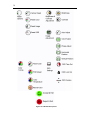
OSD Sub-Group Icons
The sub-group OSD icons are shown next:
38
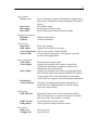
Figure 16. OSD Sub-Group Icons.
39
Reset options:
Factory reset
Reset Color
Reset Image
Reset OSD
Brightness& Contrast:
Brightness
Contrast
Color tuning:
Reset Color
RGB Adjust
Color Temperature
Natural Color
Image adjustment:
Auto Adjust
Clocks Adjust
Phase Adjust
Horizontal &
Vertical Position
OSD settings:
OSD Time Out
OSD Lock Out
OSD position
Exit options:
Smiley face
Unhappy face
Reset all settings to a factory default and re-synchronize on
input signal. Accept/Reject menu will appear if this option
chosen.
Reset RGB settings.
Resynchronize on input signal.
Reset OSD position, timeout and lock settings.
Brightness adjustment
Contrast adjustment
Reset color settings.
Adjust Red/Green/Blue color space.
Choose color scheme. Default is RGB.
Fine-tune human skin palette. This option is especially
useful in video applications.
Resynchronize on input signal.
Adjust pixel-sampling clock relative to input clock.
Usually, this mechanism is automatic; manual clock
adjustment is not recommended.
Adjust pixel-sampling clock relative to input signal phase.
May be useful when connecting the MW800 XGA display
to a new input source. Note, that shadows surrounding
vertical lines are symptom of insufficient phase adjustment.
Generally, no complicated geometry adjustments are
needed for LCD. Slight horizontal or vertical position
issues may require tuning.
Specify how long to wait for user input before exiting
OSD. The options are 5 seconds, 30 seconds, 60 seconds,
and 120 seconds. The default is 5 seconds.
Lock OSD menus from user input.
Choose preferred menu position on screen.
Accept and exit.
Reject and exit.
40
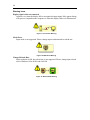
Warning Icons
Display signal cable not connected
Appears every time the display fails to recognize the input signal. May appear during
reset process, suspend/resume sequence or when the display cable was disconnected.
Figure 17. Connection Warning
Mode Error
Input mode is not supported. Please, change input resolution and/or refresh rate.
Figure 18. Mode Error Warning
Change Refresh Rate
Input resolution is OK, but refresh rate is not supported. Please, change input refresh
rate in Windows OS to 60 Hz and click OK.
Figure 19. Refresh Rate Warning
41
Appendix F: Troubleshooting
Many problems can be solved without outside assistance by following the
troubleshooting procedures provided via the online help or in the device documents,
operating system and software applications. Most software applications contain
troubleshooting procedures and explanation of error information. If you suspect a
software issue, refer to the operating system or application troubleshooting guides.
NOTE: This manual does not cover operating system issues. Please, refer to
Microsoft® Windows® XP Professional or Windows 2000 documentation.
This chapter contains helpful hints to follow when you encounter any problem. If a
problem persists after you follow the instructions in this chapter, contact your system
administrator for help.
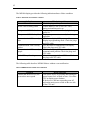
The following table describes MW800 error messages that warn you about
conditions that might prevent normal operation.
Table 1. MW800 error messages
Message
Vehicle Battery is Low. The
system will shutdown in 3
minutes.
MW800 CPU temperature is
high. The system will shutdown
in 3 minutes.
Warning condition is over
MW800 CPU temperature is
low. The system will shutdown
in 3 minutes.
PC Card error was detected.
Please remove the PC Card
device and then press OK.
MW800 hard drive heater may
be malfunctioned.
Over current is detected in
device connected to Firewire
port.
Do the following
The car battery voltage is below of the low
operational limit. Please save your work before
shutting down
The internal temperature is higher than the
valid limit.
Please save your work before shutting down.
Never turn on the device until it cools down to
normal operating temperature.
Cancel Warning
The internal temperature is below of the valid
limit.
Please save your work before shutting down.
Never turn on the device until it heats up to
normal operating temperature.
Card Bus over-current is discovered. Please
remove the PC Card device and than press OK
Heater over-current is discovered. Please,
contact your system administrator.
The MW800 cannot work with this Firewire
device. Please, disconnect the device.
42
The MW800 display provides the following indication about a failure condition.
Table 2. Indications about failure condition
Indication
Power LED is off
Power LED is steady yellow
Temperature LED blinks red
Temperature LED blinks yellow
Communication LED is steady
blue
Communication LED is steady
yellow
Communication LED is steady
purple
Link LED is yellow & green
What’s the problem
Check the plug and the power cord.
Vehicle battery is low (9.4 to 10.3 VDC)
during workstation power up.
Display temperature is extremely high during
power on
Display temperature is extremely low during
operation.
CPU box to display USB power problem, or
display in programming mode. Check the plugs
and CPU cable.
CPU box fails to communicate with display.
Check the plugs and CPU cable.
CPU box to display USB power and
communication problem. Check the plugs and
CPU cable.
NO valid input signal from CPU box. Check
the plugs and CPU cable.
The following table describes MW800 failures without a user notification.
Table 3. MW800 failures without user notification
Problem
Cannot turn the device off, the
system does not respond
Do the following
Turn off the device by pressing and holding the
power button for 6 seconds or more. Use either
CPU or display power buttons.
If the device is still not responding, turn off
and on the main power switch on the rear side
of the CPU unit.
43
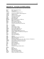
Appendix G: Acronyms and Abbreviations
The following acronyms and abbreviations are used in this document:
BIOS
CD
CDMA
CMOS
COM
COTS
CPU
CRT
DDR
DRAM
DVI
EME
FAQ
FCC
GB
GHz
GPI
GPO
GPRS
GPS
iDEN
IEEE
I/O
LAN
LCD
MB
MPS
MW
NIT
NMEA
NTCS
OS
OSD
PAL
PC
PCI
PWR
RI
RF
SIM
SVGA
TAIP
Basic Input Output System
Compact Disk
Code Division Multiple Access
Configuration Memory Operating System
Communication
Commercial Of-The-Shelf
Central Processor Unit
Cathode Ray Tube
Double Data Rate
Dynamic Random Access Memory
Digital Video Interface
Electromagnetic Emission
Frequently Asked Questions
Federal Communications Commission
Gigabyte
Gigahertz
General Purpose Input
General Purpose Output
General Packet Radio Service
Global Positioning System
Integrated Digital Enhanced Network
Institute of Electrical and Electronic Engineers
Input/Output
Local Area Network
Liquid Crystal Display
Megabyte
Maintenance Programming Software
Mobile Workstation
Near Infrared Transmission (also cd/m2, a measure of luminance)
National Marine Electronics Association
National Television System Committee
Operating System
On-Screen Display
Phase Alternation Line
Personal Card
Peripheral Component Interconnect
Power
Ring Indicator
Radio Frequency
Subscriber Identity Module
Super Video Graphics Array
Trimble Advance Interface Protocol
44
TFT
TSIP
TTL
UHF
UL
USB
VCR
VDC
WWAN
WLAN
XGA
Thin Film Transistor
Trimble Standard Interface Protocol
Transistor-Transistor Logic
Ultra High Frequency
Underwriters Laboratories
Universal Serial Bus
Videocassette Recorder
Volts Direct Current
Wireless Wide Area Network
Wireless Local Area Network
eXtended Video Graphics Array
HOW TO REACH US:
Government & Enterprise Mobility Solutions
1301 E. Algonquin Road,
Schaumburg, IL 60196
In the USA call: 1-888-567-7347
Outside the USA call: 847-576-5000
Visit our Web site at
http://www.motorola.com
a
MOTOROLA and the Stylized M Logo are registered in the
U.S. Patent and Trademark Office. All other product or
service names are the property of their respective owners.
Copyright © 2005 Motorola all rights reserved.