1
USER MANUAL
VDTU2A-301
VDSL2 LAN Extender
CTC Union Technologies Co.,
LEGAL
The information in this publication has been carefully checked and is believed to be entirely
accurate at the time of publication. CTC Union Technologies assumes no responsibility, however,
for possible errors or omissions, or for any consequences resulting from the use of the information
contained herein. CTC Union Technologies reserves the right to make changes in its products or
product specifications with the intent to improve function or design at any time and without notice
and is not required to update this documentation to reflect such changes.
CTC Union Technologies makes no warranty, representation, or guarantee regarding the suitability
of its products for any particular purpose, nor does CTC Union assume any liability arising out of
the application or use of any product and specifically disclaims any and all liability, including
without limitation any consequential or incidental damages.
CTC Union products are not designed, intended, or authorized for use in systems or applications
intended to support or sustain life, or for any other application in which the failure of the product
could create a situation where personal injury or death may occur. Should the Buyer purchase or
use a CTC Union product for any such unintended or unauthorized application, the Buyer shall
indemnify and hold CTC Union Technologies and its officers, employees, subsidiaries, affiliates,
and distributors harmless against all claims, costs, damages, expenses, and reasonable attorney fees
arising out of, either directly or indirectly, any claim of personal injury or death that may be
associated with such unintended or unauthorized use, even if such claim alleges that CTC Union
Technologies was negligent regarding the design or manufacture of said product.
TRADEMARKS
Microsoft is a registered trademark of Microsoft Corp.
HyperTerminal™ is a registered trademark of Hilgraeve Inc.
FCC WARNING:
This equipment has been tested and found to comply with the limits for a Class A digital device,
pursuant to Part 15 of the FCC Rules. These limits are designed to provide reasonable protection
against harmful interference when the equipment is operated in a commercial environment. This
equipment generates, uses, and can radiate radio frequency energy and if not installed and used in
accordance with the instruction manual may cause harmful interference in which case the user will
be required to correct the interference at their own expense.
NOTICES:
(1) The changes or modifications not expressively approved by the party responsible for
compliance could void the user's authority to operate the equipment.
(2) Shielded interface cables and AC power cord, if any, must be used in order to comply with the
emission limits.
(3) This is a Class A product. In a domestic environment this product may cause radio interference
in which case the user may be required to take adequate measures.
CISPR PUB.22 Class A COMPLIANCE:
This device complies with EMC directive of the European Community and meets or exceeds the
following technical standard. EN 55022 - Limits and Methods of Measurement of Radio
Interference Characteristics of Information Technology Equipment. This device complies with
CISPR Class A.
CE NOTICE
Marking by the symbol CE indicates compliance of this equipment to the EMC directive of the
European Community. Such marking is indicative that this equipment meets or exceeds the
following technical standards: EN 55022:1994/A1:1995/A2:1997 Class A and EN61000-3-2:1995,
EN61000-3-3:1995 and EN50082-1:1997
CTC Union Technologies Co., Ltd.
Vienna Technology Center
8F, No. 60, Zhouzi St.,
Neihu District, Taipei, 114
Taiwan
VDTU2A-301 VDSL2 LAN Extender, Installation and Operation Manual
Version 1.0 April 2008
Firmware Version Notice: TBA
Table of Contents
Tables of Contents............................................................................................................................i
Chapter 1
Introduction .............................................................................................................7
1.1
1.2
1.3
Chapter 2
2.1
2.2
2.3
Features ................................................................................................................... 7
Specification............................................................................................................ 8
Applications ............................................................................................................ 8
Hardware Installation ..............................................................................................9
Front Panel .............................................................................................................. 9
Real Panel.............................................................................................................. 11
Installation............................................................................................................. 11
Appendix I.....................................................................................................................................13
Connector Architecture ......................................................................................................... 13
i
Chapter 1. Introduction
Chapter 1. Introduction
CTC Union’s VDTU2A-301 LAN Extender is a Long Reach Ethernet media converter with
one Ethernet port (RJ-45 connector) and one VDSL port (RJ-45 connector) This model is a
bridge mode modem, well accommodating VDSL2 (Very-high-data-rate Digital Subscribe
Loop) technologies to extend Ethernet service over single-pair phone line. Supporting both
symmetric and asymmetric transmission, it can reach up to 100/75 Mbps bandwidth (line rate)
within 300M or 10/10 Mbps (line rate) for 1 Km long range connections. By providing ultrahigh speed, VDTU2A-301 LAN Extender makes your telephone line achieve its best
performance than before. It has the advantage of minimum installation time (simply as plug-nplay) and minimum expense by allowing video streaming and data to share the same
telephone pair without interference.
1.1 Features
¾
¾
¾
¾
¾
¾
¾
Cost effective bridge function to connect two Ethernet LAN
Support flow control on Fast Ethernet port via PAUSE frame or Back Pressure
IEEE 802.1Q VLAN tag transparent
Easy installation via simple plug-and-play
Selectable CPE and CO mode via DIP switch:
Two working modes are built in the same unit, which keep the flexibility of
installation and easy provision of service but lower inventory of service provider.
Selectable fast and interleaved mode:
Fast mode guarantees a minimum end to end latency less than1 ms. Interleaved
mode provides impulse noises protection for any impulse noise with a duration less
than 250 us, Interleaved mode has a maximum end to end latency of 10 m sec.
Interleaved mode is the default mode.
Selectable target data rate and target SNR margin:
User has the ability to select fixed SNR margin (9 dB) or fixed target data rate.
When fixed SNR margin is selected, the systems will maintain the SNR margin at 9
dB across all usable loop length. When fixed target data rate is selected, the
system will lock the data rate up to 50 Mbps/30 Mbps whenever the calculated
SNR margin is higher than 9 dB. This gives best system stability and is the default
mode.
7
Chapter 1. Introduction
1.2 Specification
¾
LAN Interface:
RJ-45 connector
Complying with IEEE 802.3/802.3u/802.3x
10/100 Base-T Auto-Negotiation, Auto-MDI/MDI-X.
¾ VDSL Interface:
RJ-45 connector
DMT Encoding
Complying with ITU-T G993.1/993.2
On-board surge protection
¾ 4-position DIP Switch
¾ LED:
LAN: ACT/LNK, 10/100 Mbps, Half/Full Duplex
VDSL: Power On/Off, CO/CPE, Idle/Trained/Link
¾ Power supply:
DC single 12 Volt over 35mm DC jack
Power consumption: 42 Watt maximum.
1.3 Applications
LAN Extender Application
8
Chapter2. Hardware Installation
Chapter 2. Installation
This chapter shows the front panel and how to install the hardware.
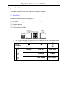
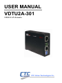
2.1 Front Panel
Please see the side view below configure 2.1:
Front panel can be separated into five parts fron left to right:
(1) DIP switch
(2) RJ-45 connector for Ethernet
(3) LEDs for Ethernet
(4) LED for VDSL
(5) RJ-45 connector for VDSL
1.
The RJ-45 is designed to connect to the Local Network with the Unshielded Twisted
Pair (UTP) cable. The LEDs on top of RJ-45 connector show the status below:
z
{
Blinking
On
Off
Activity
Link UP
Link Down
{
100Mbps
10Mbps
{
Full Duplex
Half Duplex
LED for
Ethernet
{
9
Chapter2. Hardware Installation
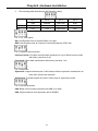
2.
The following table describes the DIP Switchs’ setting.
Pin 1
Pin 2
Pin 3
Pin 4
Side
Channel
Rate Limit
SNR
Off
CO
Interleave
Symmetric
9dB
On
CPE
Fast
Asymmetric
6dB
Pin 1: CO, CPE switch
GO: LAN Extender acts as Central Office (CO) side.
GPE: LAN Extender acts as Customer Premise Equipment (CPE) side.
Pin 2: Impulse noise protection
Interleave mode: Provides communication protection for up to 250ms impulse noise
with latency less than 6 ms.
Fast mode: Direct data transmission with latency less than 1 ms.
Pin 3: Band Plan
Symmetric: Support the band plan G.997 and provide the symmetric transmission on
both down stream and upstream.
Asymmetric: Provides highest line rate in short range in asymmetric mode.
Pin 4: General protection
9dB: Better channel noise protection with SNR up to 9 dB
6dB: Original channel noise protection with 6 dB SNR.
10
Chapter2. Hardware Installation
3.
The following table describes the LEDs’ function of the product.
LED for
VDSL
blinking
z On
{ Off
{
Power ON
Power OFF
{
CPE-mode
CO-mode
Linked
Off line
{
Slow:
Fast:
Idle
Training
2.2 Real Panel
The DC Jack on the rear panel can be connected to power supply adaptor with the DC input.
2.3 Installation
Please see the illustation below
11
Chapter2. Hardware Installation
12
Appendix 1. Connector Architecture
Connector Architecture
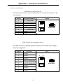
Ethernet Port Connector (RJ-45)
The Ethernet Port interface is a 8 position Modular Jack. The table below displays the pin
out assignments.
Pin Number
Assignment (MDI-X)
1
RX+;
Receive data +
2
RX-;
Receive data -
3
TX+;
Transmit data +
4
Not used
5
Not used
6
TX-;
7
Not used
8
Not used
Figure
1
8
1
8
Front View
Transmit Data Top View
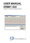
VDSL Interface Pin Assignments (RJ-45)
The VDSL interface is standard eight-pin modular jack. The table below displays
the pin out assignments.
Pin Number
Description
Figure
1
Not used
2
Not used
3
Not used
4
ANALOG Input/Output
5
ANALOG Input/Output
6
Not used
7
Not used
8
Not used
1
8
1
Front View
Top View
13
8
Appendix 1. Connector Architecture
14
Transmission Series
CTC Union Technologies Co., Ltd.
Vienna Technologies Center (Neihu Technology Park)
8F, 60 Zhouzi St., Neihu, Taipei, Taiwan 114
Phone:(886) 2.2659.1021 Fax:(886) 2.2799.1355
E-mail: [email protected] http://www.ctcu.com