1
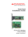
Host Card Installation Guide PCI to PCI Interface Model: PCIHIF68 Model: PCIHIF64LP Copyright © 2006 Mobility Electronics, Inc. This publication is protected by Federal Copyright Law, with all rights reserved. No part of this publication may be copied, photocopied, reproduced, stored in a retrieval system, translated, transmitted or transcribed, in any form or by any means manual, electric, electronic, electro-magnetic, mechanical, optical or otherwise, in whole or in part without prior written consent from Mobility Electronics, Inc. Limitation of Liability Information presented by Mobility in this guide is believed to be accurate and reliable. However, Mobility assumes no responsibility for its use. No license is granted by implication or otherwise to any rights of Mobility. Product specifications and prices are subject to change without notice. Trademark References Trademarks and registered trademarks are proprietary to their respective manufacturers. M A G M A Table of Contents PREFACE ............................................................................................... I What’s in this Guide ................................................................................ i Advisories ...............................................................................................ii Safety Instructions...................................................................................ii When Working Inside a Computer .........................................................iii Protecting Against Electrostatic Discharge ............................................iv CHAPTER 1 INTRODUCTION .......................................................... 1 General Specifications ........................................................................... 1 Pre-Installation Information .................................................................... 1 Parts List ................................................................................................ 1 Tools Required for Installation................................................................ 1 CHAPTER 2 HARDWARE INSTALLATION ..................................... 2 Install Host Card..................................................................................... 2 Attach Power and Expansion Cable(s)................................................... 3 Apply Power Correctly............................................................................ 4 CHAPTER 3 VERIFY INSTALLATION.............................................. 6 Windows 2000 and XP........................................................................... 6 Using the Device Manager............................................................................ 6 Mac OS X............................................................................................... 8 CHAPTER 4 TROUBLESHOOTING ............................................... 11 Identifying the Problem ........................................................................ 11 Device Manager Shows a Bang ................................................................. 12 My Computer Can’t Find the PCI Expansion System ................................. 13 Windows Error Codes ................................................................................. 14 CHAPTER 5 HOW TO GET MORE HELP....................................... 16 Product Registration............................................................................. 16 Frequently Asked Questions (FAQ) ..................................................... 16 Contacting Technical Support .............................................................. 16 MAGMA Debug Utility ................................................................................. 17 PCIScope Software Utility........................................................................... 18 Returning Merchandise to MAGMA...................................................... 20 APPENDIX A COMPLIANCE .......................................................... 21 FCC...................................................................................................... 21 Industry Canada................................................................................... 21 CE ........................................................................................................ 21 Table of Contents i M A G M A ii Table of Contents M A G M A Preface What’s in this Guide This Host Card Installation Guide is designed to accompany a Magma Expansion Chassis User Guide. This guide provides easy instructions to install your host card, verify the installation was completed correctly, and troubleshoot the installation, if necessary. The corresponding Expansion Chassis User Guide provides similar information for your Magma expansion chassis. This guide is divided into the following parts: Chapter 1: Provides General Specifications and Parts List. Chapter 2: Briefly explains Host Card installation. Chapter 3: Explains how to verify a successful installation. Chapter 4: Provides troubleshooting assistance. Chapter 5: Explains where to get technical support. Appendix A: Provides information about Compliance. Preface i M A G M A Advisories Five types of advisories are used throughout this guide to provide helpful information, or to alert you to the potential for hardware damage or personal injury. They are Note, Important, Caution, Warning, and Danger. The following is an example of each type of advisory. NOTE Used to amplify or explain a comment related to procedural steps or text. IMPORTANT Used to indicate an important piece of information or special “tip” to help you CAUTION Used to indicate and prevent the following procedure or step from causing damage to the equipment. WARNING Used to indicate and prevent the following step from causing injury. DANGER or STOP Used to indicate and prevent the following step from causing serious injury or significant data loss. Disclaimer: We have attempted to identify most situations that may pose a danger, warning, or caution condition in this guide. However, Mobility Electronics, Inc. does not claim to have covered all situations that might require the use of a Caution, Warning, or Danger indicator. Safety Instructions Always use caution when servicing any electrical component. Before working inside a computer, read the following instructions and safety guidelines to prevent damage to the product and to ensure your own personal safety. Refer to the “Advisories” section for advisory conventions used in this guide, including the distinction between Dangers, Warnings, Cautions, and Notes. ii Preface M A G M A ♦ Always use caution when handling/operating the computer. Only qualified, experienced, authorized electronics personnel should access the interior of the computer. The power supplies produce high voltages and energy hazards, which can cause bodily harm. ♦ Use extreme caution when installing or removing components. Refer to the installation instructions in this guide for precautions and procedures. If you have any questions, please contact Mobility Technical Support. WARNING High voltages are present inside the expansion chassis when the unit’s power cord is plugged into an electrical outlet. Disconnect the power cord from its source before removing the system cover. Never modify or remove the radio frequency interference shielding from your workstation or expansion unit. To do so may cause your installation to produce emissions that could interfere with other electronic equipment in the area of your system. When Working Inside a Computer Before taking covers off a computer, perform the following steps: 1. Turn off the computer and any peripherals 2. Disconnect the computer and peripherals from their power sources to prevent electric shock or system board damage. 3. Disconnect any telephone or telecommunications lines from the computer. In addition, take note of these safety guidelines when appropriate: ♦ To help avoid possible damage to systems boards, wait five seconds after turning off the computer before removing a component, removing a system board, or disconnecting a peripheral device from the computer. ♦ When you disconnect a cable, pull on its connector or on its strain-relief loop, not on the cable itself. Some cables have a connector with locking tabs. If you are disconnecting this type of cable, press in on the locking tabs before disconnecting the cable. As you pull connectors apart, keep them evenly aligned to avoid bending any connector pins. Also, before connecting a Preface iii M A G M A cable, make sure both connectors are correctly oriented and aligned. CAUTION Do not attempt to service the system yourself except as explained in this guide. Follow installation instructions closely. Protecting Against Electrostatic Discharge Electrostatic Discharge (ESD) Warning Electrostatic Discharge (ESD) is the enemy of semiconductor devices. You should always take precautions to eliminate any electrostatic charge from your body and clothing before touching any semiconductor device or card by using an electrostatic wrist strap and/or rubber mat. Static electricity can harm system boards. Perform service at an ESD workstation and follow proper ESD procedure to reduce the risk of damage to components. Mobility strongly encourages you to follow proper ESD procedure, which can include wrist straps and smocks, when servicing equipment. You can also take the following steps to prevent damage from electrostatic discharge (ESD): iv ♦ When unpacking a static-sensitive component from its shipping carton, do not remove the component’s anti-static packaging material until you are ready to install the component in a computer. Just before unwrapping the anti-static packaging, be sure you are at an ESD workstation or grounded. ♦ When transporting a sensitive component, first place it in an anti-static container or packaging. ♦ Handle all sensitive components at an ESD workstation. possible, use anti-static floor pads and workbench pads. ♦ Handle components and boards with care. Don’t touch the components or contacts on a board. Hold a board by its edges or by its metal mounting bracket. Preface If M A G M A Chapter 1 Introduction General Specifications The MAGMA PCI Host Card is the connection between your PCI Expansion System and your host computer. Model PCIHIF68 is a 32-Bit host card. Model PCIHIF64LP is a 64-Bit low-profile host card that will also work in a 32-Bit PCI slot. The expansion system provides a general-purpose bus expansion chassis for the Peripheral Component Interconnect (PCI) local bus. MAGMA expansion chassis configurations are available in 1 Slot (for both full and half sized PCI cards), 2 Slot, 4 Slot, 7 Slot, and 13 Slot. The expansion chassis’s are fully compliant with the PCI Local Bus Specification. Pre-Installation Information Before using the MAGMA expansion chassis you should perform the following steps: • • • Inventory the shipping carton contents for all of the required parts Gather all of the necessary tools required for installation Read this guide Parts List The following parts are provided: Qty 1 1 1 1 Item PCI Host Card (32-bit or Low Profile 64-bit) Low-profile mounting bracket (PCIHIF64LP Only) Software CDROM Installation Guide Tools Required for Installation In order to complete the installation, you will need a Phillips-head screwdriver. Chapter 1 Introduction 1 M A G M A Chapter 2 Hardware Installation IMPORTANT It is recommended that you refer to the separate Expansion Chassis User’s Guide included with your Magma Expansion Chassis product for complete system installation information. The following installation instructions briefly explain the connection of the host card to the host computer only. Install Host Card Power down your computer. Use the procedures for shutting down your operating system and shutting off power to your system provided in your owner’s manual or system documentation. After the host computer is off and all power cords disconnected, remove the cover and insert the PCI host card into an appropriate vacant PCI slot by gently pushing the card until it is firmly seated. Notice that the standard PCI slots are located at a closer distance to the edge of the computer’s motherboard than are the PCI Express slots. You should also be aware that some host computers may also contain 3.3V, 5V, and/or Universal PCI slots. Your PCI Host Card can only be inserted in 3.3V or Universal PCI slots. DO NOT FORCE IT into a slot. Check to be sure you are not trying to install it into a 5V PCI slot, or a PCIe slot. Once you have the host card firmly inserted into the correct PCI slot secure the card to the slot with a mounting screw. 2 Chapter 2 Installation M A G M A If you don’t have any empty PCI slots, you can remove a PCI card to create a vacant slot. This PCI card can later be installed in a vacant slot in your new expansion chassis. The PCIHIF64LP is a “half-height” PCI card attached to a “full-height” bracket for convenient mounting in most desktop computers. It is also shipped with a low profile card bracket to allow mounting on low profile computer systems. For low profile case applications, you may need to change the mounting bracket to the low profile bracket that shipped with your system. This is done by removing the screws that hold the card to the bracket. Be sure you are using proper ESD procedures when completing this action. For more information on installing PCI Cards, please refer to your computer’s user manual or system documentation. Attach Power and Expansion Cable(s) Carefully position the Magma expansion chassis so that the cable supplied with your expansion system will conveniently reach from the connector of the host card to the connector(s) on the back of the expansion chassis. The cable(s) connect to the host card using thumbscrews; therefore no tools are required to attach the cables. However, in order to create the most robust connection, it is recommended that you tighten the thumbscrews with a screwdriver. Attach one end of the PCI expansion cable to the host card and the other end to the rear side of the expansion chassis. Chapter 2 Installation 3 M A G M A Connect all power cords to the power-in receptacle located at the rear of the enclosure. Secure the cable to the computer with the captive thumbscrews. It is important that the cable be attached securely to the connectors at both ends. If you purchased the “half-height” PCIHIF64LP because your host computer is a low-profile chassis and you need to connect it to a 32-bit expansion chassis, be sure to connect your expansion cable to the 32-bit (Teal) side of the host card. Finish connecting the power cable to your expansion system using instructions contained in the Expansion Chassis User Guide. Turn on the power to the expansion system first, and then the host computer. Apply Power Correctly You must apply power to the Magma expansion chassis BEFORE you power up your computer. This will allow the higher numbered PCI buses in the PCI bus hierarchy to be at a stable state when the host system issues its master power-on bus reset. In systems that perform automatic PCI bus configuration, this will allow the configuration code to recognize the PCI bus hierarchy and any attached devices. There is an On/Off switch on the expansion chassis, as well as an LED indicator to indicate power status. For information about your particular 4 Chapter 2 Installation M A G M A expansion chassis, refer to the separate Expansion Chassis User’s Guide. Verify that the LED power indicator is ON. IMPORTANT When powering up, pay close attention to LEDs on the host card inside the computer. Two LEDs must be solid green before the system will function properly. If both LEDs are not lit, you may need to adjust the dip switch settings as described below. The PCIHIF68 (32-Bit PCI host interface card, labeled 01-03527-00) includes a voltage switch in the top right corner of the board that may need to be adjusted for proper installation. It is an easy process to determine if the voltage switch needs to be adjusted for your configuration. 1. If both LEDs shown below are lit, DO NOT adjust the dip switch. 2. If only the +5V LED is lit (closed to the end of the board), shut down your computer, then flip the switch to the ON position before continuing. When you power up the computer again, both LEDs should be lit. STOP DO NOT TURN ON THE MAGMA EXPANSION CHASSIS UNTIL YOU HAVE SHUT DOWN YOUR HOST COMPUTER COMPLETELY! It can cause a system lockup and loss of any unsaved data. Chapter 2 Installation 5 M A G M A Chapter 3 Verify Installation The MAGMA PCI Host Card is not visible to the Windows’ Device Manager or the Apple System Profiler until the Expansion System has been successfully connected and properly powered on. Therefore, you will need to connect your Expansion System and turn it on before you can verify the MAGMA PCI Host Card installation. See your Expansion Chassis User Guide for information on how to connect and power-up your Expansion System. Windows 2000 and XP To verify a successful installation on, find the ‘My Computer’ icon on your desktop or on the Start Menu. Right-click and select ‘Manage.’ Using the Device Manager Select ‘Device Manager’ from the items in the left side of the Computer Management Window. Then click on the View Menu and select View Devices by Connection. 6 Chapter 3 Verify Installation M A G M A To see if your installation is completed: Click on the ‘+’ sign to the left of the ACPI (BIOS) to open it. This is typically found at the top of the Device Manager Window. Click on the ‘+’ sign to the left of the PCI Bus to see all PCI Bus connections. Click the ‘+’ sign to the left of the line containing the words “PCI Bridge” or something similar. You should now see the PCI Standard PCI-to-PCI bridge immediately below it. When installed correctly, you will see two “PCI to PCI Bridges” below your system’s PCI Controller. If your Magma expansion system uses a 13 Slot backplane, the Device Manager will display three bridges instead of two as shown above. If everything is OK, then the MAGMA PCI Host Card installation is complete. You can now proceed to the Expansion Chassis User Guide rd for help with the installation of 3 Party PCI Cards. Chapter 3 Verify Installation 7 M A G M A If, however, the installation was unsuccessful, you may not see the PCI to PCI Bridge, or it will have a small yellow in front of it. If any of these devices are not displayed as shown above, you should shut down your system (host computer first, then the expansion chassis) and reconnect the cables and reseat the PCI Host Card to ensure that you have a solid connection. Then restart the MAGMA expansion chassis, followed by the host computer. Next, try to verify the installation again, as shown above. If you are still having problems, review Chapter 4, Troubleshooting before contacting Mobility Technical Support at (858) 530-2511. Additional troubleshooting help is available in your Expansion Chassis User Guide and on the website at www.Magma.com. Mac OS X When using Mac OS X no additional software or drivers are needed. The operating system should automatically recognize the Magma host card and expansion chassis. Select “About This Mac” under the Apple Icon Then click the “More Info” button. Open the Hardware tab and choose PCI Cards from the drop down list. 8 Chapter 3 Verify Installation M A G M A MAC OS 10.3.x & 10.4.x Next, click on the PCI Card item. You should see a pci-bridge device listed under PCI as shown below: Mac OS 10.3.x & 10.4.x Any PCI Cards you install in the expansion chassis will appear behind the pci-bridge device. If your Magma Expansion System uses a 13 Slot backplane, the Apple Profiler will display three bridges instead of two as shown above. MAC OS 10.2.x Next, click on the Devices tab. You should see a pci-bridge device listed under PCI as shown below: Any PCI Cards you install in the expansion chassis will appear behind the pci-bridge device. Mac OS 10.2.x Chapter 3 Verify Installation 9 M A G M A If any of these devices are not displayed as shown above, you should shut down your system (computer first, then the expansion chassis) and reconnect the cables and the PCI expansion host card to ensure that you have a solid connection. Then restart the MAGMA expansion chassis followed by the computer. Next, try to verify the installation again, as shown above. If you are still having problems, contact Mobility Technical Support at (858) 530-2511. 10 Chapter 3 Verify Installation M A G M A Chapter 4 Troubleshooting Identifying the Problem The PCI to PCI Expansion System is correctly displayed as a “PCI standard PCI-to-PCI bridge”. When connected and functioning correctly, this Expansion System will be displayed as follows: If the above Device Manager image is not what you are seeing when you verify your installation, you may want to try the following troubleshooting steps to help you locate and resolve your installation issues - without having to call Technical Support. NOTE Remember that the 13 Slot chassis will display an extra bridge. Chapter 4 Troubleshooting 11 M A G M A If you have trouble with the MAGMA expansion system, you need to identify the problem before you can fix it. For starters, verify that any/all cards are inserted correctly and securely in the correct slot and that all cables are connected properly. Be sure you followed the instructions in Chapter 2 and Chapter 3 of this Installation Guide, or in your Expansion Chassis User Guide. Always remember to power On and Off correctly when rechecking and testing your installation. If you are still having problems, try these simple troubleshooting steps. The Device Manager Shows a Bang My Computer Can’t Find the PCI Expansion System Windows Error Codes Device Manager Shows a Bang If the PCI to PCI Bridge is visible, but contains a a problem that must be fixed. in front of it, it has To identify the problem, right-click on the line and select “Properties” from the pop-up menu. Look for the “Error Code” in the box in the center of the Properties Window and then go to the following Windows Error Code section for information on how to resolve this issue. 12 Chapter 4 Troubleshooting M A G M A My Computer Can’t Find the PCI Expansion System If the expansion system is not visible in your Windows Device Manager or your Apple System Profiler at all, you will need to turn off your computer (first) and then the MAGMA expansion chassis (second) and test all cords and cables to ensure you have everything connected correctly. If everything seems to be connected correctly, and you are sure you have applied power correctly (power up expansion chassis first and then the computer), then try these additional troubleshooting steps: Try moving the Host Card to a different PCI slot. Double-check the expansion cable to ensure it is connected correctly at both ends. Try another cable, if you have one. If the expansion system is still not visible after trying all of the above steps, go to Chapter 5 to see about getting additional help. If the PCI to PCI Bridge is now visible, but contains a has a problem that must be fixed. in front of it, it To identify this problem, follow the instructions shown in the previous section “Device Manager Shows a Bang.” Resolve the identified problem or go to Chapter 5 to see about getting additional help. Chapter 4 Troubleshooting 13 M A G M A Windows Error Codes If you are having a problem with one of your devices, and the Device status box shows a Windows Error Code, refer to the following list of error codes for guidance: Error Code Description/Action rd There is a problem with the 3 Party PCI Card driver. Contact the PCI Card’s manufacturer for updated drivers. If all else fails, contact Technical Support for further assistance. 10 On the Bridge: If you receive error code 12 on the first PCI to PCI Bridge, call Technical Support. 12 On the PCI Card: This usually means the memory, I/O, or prefetch is more than has been allocated. Call Technical Support. rd 28 (PCI Card) 14 The driver for the 3 Party PCI Card is not installed on your system. Reinstall the PCI Card driver following the manufacturer’s instructions. If that fails to fix the problem, call the card manufacturer for new drivers. Chapter 4 Troubleshooting M A G M A Error Code 1 Description/Action The PCIe host card or expansion chassis are not working correctly. Reinstall the PCIe host card into the computer’s PCIe slot and recheck all cable connections. If the error code remains, try another PCIe slot. If you still have the error, call Technical Support. For all other error codes, call: On the PCI to PCI Bridge: Technical Support Other Codes On the PCI Card: Card Manufacturer’s Technical Support, after first verifying that the MAGMA expansion system is installed properly. If you are still having problems, contact Technical Support for more help. Chapter 4 Troubleshooting 15 M A G M A Chapter 5 How to Get More Help Product Registration While registration is not required to resolve warranty claims, it will help make any warranty claim easier to complete. For your convenience, please register your product using our online registration form at www.magma.com/support. Frequently Asked Questions (FAQ) You can visit the Technical Support FAQ pages on the Internet at: www.magma.com/support/ Contacting Technical Support Our support department can be reached by fax at (858) 530-2733 or by phone at (858) 530-2511. Support is available Monday through Friday, 8:00 AM to 5:00 PM PT. When contacting MAGMA Technical Support, please be sure to include the following information: 1) Name 7) Serial Number 2) Company Name 8) Computer Make 3) Phone Number 9) Computer Model 4) Fax Number 10) Operating System and Version 5) Email Address 11) Make/Model of PCI cards in expansion chassis 6) Model Number 12) Detailed description of the problem You can also visit our web site at: www.magma.com/support/ For a quick response, use the Technical Support and RMA Request Form available in the Support Section of the website. Simply complete the form with all required information. Please make sure that your problem description is sufficiently detailed to help us understand your problem. For example: Don’t say “Won’t boot up.” Do say “Tried all the steps in the Troubleshooting Section and it still won’t boot up.” For faster diagnosis of your problem, please run the two utility programs described in the following sections and include the diagnostic files they generate with your email. 16 Chapter 5 How to Get More Help M A G M A MAGMA Debug Utility Occasionally, Mobility Technical Support may request Windows users to produce and email a MAGMA debug log file to help them resolve your problem. This file should be emailed to [email protected]. This file should have a “.log” file extension. To create the *.log file, follow these instructions: 1. 2. 3. 4. 5. Locate a file called dbgview.exe on the MAGMA CDROM. Double-click on the file dbgview.exe While the dbgview screen is open, locate and double-click on a file called dump.exe on the MAGMA CDROM. Switch back to the dbgview screen, which is now filled with data. Save this file and email to [email protected] upon request. Use the “Save As Type” drop-down arrow to select a file type of (*.LOG). Chapter 5 How to Get More Help 17 M A G M A PCIScope Software Utility PCIScope is a powerful tool for Windows users. It was designed by a Germany company called APSoft. This software utility is a valuable resource to explore, examine and debug the PCI subsystem of your computer. It was made to fit the requirements of the most demanding users, especially engineers, programmers, and system administrators, and to integrate all advanced functions and tools into one product. Please visit www.tssc.de for more information about the capabilities of PCIScope and other utilities offered by APSoft. An evaluation version of PCIScope is available for download at www.tssc.de. (You can purchase an inexpensive license from APSoft for use beyond the evaluation period.) PCIScope has proven to be extremely useful when verifying and debugging configurations involving the MAGMA PCI Expansion Systems under any Windows platform. PCIScope can provide information to you and our Technical Support Group such as PCI Bus Numbering, Resource Allocation, and other information that may prove useful when debugging expansion chassis or PCI card problems. If you are experiencing problems setting up your system, you should run PCIScope before contacting the Mobility Technical Support Group. With the MAGMA expansion chassis powered up and connected to your computer, load and launch the PCIScope application. The PCIScope Program will be installed on your computer and a window similar to the one shown below will appear. (The example was taken from a Compaq Armada 7400) 18 Chapter 5 How to Get More Help M A G M A You should save this data as a file on your computer. Please include your name and date as part of the file name with an extension of “.bpd.” This file should be included as an attachment when submitting a Technical Support request at www.magma.com/support. Chapter 5 How to Get More Help 19 M A G M A Returning Merchandise to MAGMA If factory service is required, a Service Representative will give you a Return Merchandise Authorization (RMA) number. Put this number and your return address on the shipping label when you return the item(s) for service. MAGMA will return any product that is not accompanied by an RMA number. Please note that MAGMA WILL NOT accept COD packages, so be sure to return the product freight and duties-paid. Ship the well-packaged product to the address below: MAGMA RETURNS DEPT. RMA # ________ 9918 Via Pasar San Diego, CA 92126 USA It is not required, though highly recommended, that you keep the packaging from the original shipment of your MAGMA product. However, if you return a product to MAGMA for warranty repair/ replacement or take advantage of the 30-day money back guarantee, you will need to package the product in a manner similar to the manner in which it was received from our plant. MAGMA cannot be responsible for any physical damage to the product or component pieces of the product (such as the host or expansion interfaces for PCI expansion chassis) that are damaged due to inadequate packing. Physical damage sustained in such a situation will be repaired at the owner’s expense in accordance with Out of Warranty Procedures. Please, protect your investment, a bit more padding in a good box will go a long way to insuring the device is returned to use in the same condition you shipped it in. Please call for an RMA number first. 20 Chapter 5 How to Get More Help M A G M A APPENDIX A Compliance FCC NOTE: This equipment has been tested and found to comply with the limits for a Class A digital device, pursuant to part 15 of the FCC Rules. These limits are designed to provide reasonable protection against harmful interference when the equipment is operated in a commercial environment. This equipment generates, uses, and can radiate radio frequency energy and, if not installed and used in accordance with the instruction manual, may cause harmful interference to radio communications. Operation of this equipment in a residential area is likely to cause harmful interference in which case the user will be required to correct the interference at his own expense. This device complies with Part 15 of the FCC Rules. Operation is subject to the following two conditions: (1) this device may not cause harmful interference, and (2) this device must accept any interference received including interference that may cause undesired operation. Changes or modifications not expressly approved by the party responsible for compliance could void the user’s authority to operate the equipment. NOTE The assembler of a personal computer system may be required to test the system and/or make necessary modifications if a system is found to cause harmful interferences or to be noncompliant with the appropriate standards for its intended use. Industry Canada This Class A digital apparatus complies with Canadian ICES-003. Cet appareil numériqué de la classe A est conformé à la norme NMB003 du Canada CE The product(s) described in this manual complies with all applicable European Union (CE) directives. Mobility will not retest or recertify systems or components that have been reconfigured by customers. Appendix A Compliance 21 M A G M A 22 Appendix A Compliance M A G M A Mobility California, Inc. PCI Expansion Products 9918 Via Pasar, San Diego, CA 92126, USA Phone (858) 530-2511 • Fax (858) 530-2733 www.magma.com Manual P/N: 09-09911-01 Rev A