1
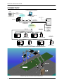
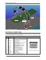
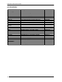
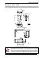
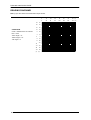
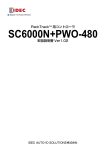
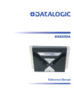
DS8100A-3002 QUICK REFERENCE GUIDE NOTE This manual illustrates a typical Local Lonworks network application. For more details refer to the DS8100A Reference Manual available on the CD. For complete scanner configuration using the Genius™ configuration program refer to the Help On Line. 821001265 (Rev. F) DS8100A-3002 QUICK GUIDE UPDATES AVAILABILITY UK/US The latest drivers and documentation updates for this product are available on Internet. Log on to: www.automation.datalogic.com I Su Internet sono disponibili le versioni aggiornate di driver e documentazione di questo prodotto. Collegarsi a: www.automation.datalogic.com F Les versions mises à jour de drivers et documentation de ce produit sont disponibles sur Internet. Cliquez sur : www.automation.datalogic.com D Im Internet finden Sie die aktuellsten Versionen der Treiber und Dokumentation von diesem Produkt. Adresse : www.automation.datalogic.com E En Internet están disponibles las versiones actualizadas de los drivers y documentación de este producto. Dirección Internet : www.automation.datalogic.com SERVICES AND SUPPORT Datalogic provides several services as well as technical support through its website. Log on to www.automation.datalogic.com and click on the links indicated for further information: PRODUCTS Search through the links to arrive at your product page which describes specific Info, Features, Applications, Models, Accessories, and Downloads including the Genius™ utility program, which allows device configuration using a PC. It provides RS232 and Ethernet interface configuration. SERVICE - Overview - Warranty Extensions and Maintenance Agreements - Sales Network- Listing of Subsidiaries, Repair Centers, Partners - Helpdesk - Material Return Authorization LEGAL NOTICES © 2005 - 2012 Datalogic Automation S.r.l. ALL RIGHTS RESERVED. Protected to the fullest extent under U.S. and international laws. Copying, or altering of this document is prohibited without express written consent from Datalogic Automation S.r.l. Datalogic and the Datalogic logo are registered trademarks of Datalogic S.p.A. in many countries, including the U.S.A. and the E.U. Genius, PackTrack, ACR, ASTRA, CD SQUARE and ID-NET are trademarks of Datalogic Automation S.r.l. All other brand and product names mentioned herein are for identification purposes only and may be trademarks or registered trademarks of their respective owners. Datalogic shall not be liable for technical or editorial errors or omissions contained herein, nor for incidental or consequential damages resulting from the use of this material. 2 DS8100A-3002 QUICK GUIDE DS8100A-3002 GENERAL VIEW 1 Figure A 1 Laser Beam Output Window 1 7 2 3 4 5 6 Figure B 1 Programming Keypad 5 TX Data LED (Green) 2 Power On LED (Green) 6 Network LED (Red) 3 Phase On LED (Yellow) 7 LCD Display 4 Encoder LED (Yellow) 2 1 Figure C 1 Lonworks 17-pin Male Connector 2 Lonworks 17-pin Female Connector 3 DS8100A-3002 QUICK GUIDE CONNECTIVITY Local Lonworks Network Host HUB ETHERNET CAB-SC6103 Cable SC6000 AUX VAC INPUT Power/Net CAB-SC6013 PWO CAB-SC6003 Extended I/O LONWORKS ENCODER BTK-8500 Bus Return CAB-85xx PS PS Aux CAB-85xx CAB-85xx A CAB-85xx CAB-85xx C E DS8100A-3002 DX8200A-3002 G DX8200A-3002 DS8100A-3002 CAB-85xx CAB-85xx B CAB-85xx D DX8200A-3002 BTK-8500 Bus Return F DS8100A-3002 H DX8200A-3002 DS8100A-3002 Large Synchronized Network with DX8200A and DS8100A Scanners E D B C F G SC6000 H Conveyor A PWO Example Large Synchronized Network Reading Station 4 DS8100A-3002 QUICK GUIDE to Host ETHERNET SC6000 VAC INPUT CAB-SC6103 AUX Working Controller Power/Net CAB-SC6013 PWO CAB-SC6003 Extended I/O LONWORKS ENCODER CAB-85xx PS PS Aux CAB-85xx CAB-85xx A CAB-85xx E C DX8200A-3002 BTK-8500 DS8100A-3002 DX8200A-3002 G DS8100A-3002 Redundancy CAB-PWO 03 to Host ETHERNET VAC INPUT SC6000 Power/Net CAB-SC6013 PWO CAB-SC6003 Extended I/O Protecting Controller LONWORKS ENCODER CAB-85xx CAB-85xx CAB-85xx B DX8200A-3002 PS PS Aux D DS8100A-3002 BTK-8500 CAB-85xx F DX8200A-3002 H DS8100A-3002 Redundant Reading Station Layout with DX8200A and DS8100A Scanners 5 DS8100A-3002 QUICK GUIDE E D B C F G SC6000 Working H Conveyor SC6000 Protecting A PWO PWO Example Redundant Reading Station ELECTRICAL CONNECTIONS Two 17-pin connectors provide access to the scanner’s local Lonworks network used for both input and output connections to build a multi-sided or omni-station system. 17-pin Lonworks Connector Pinout Pin A1 A2 6 Name GND VS 1 CHASSIS 2 n.c. 3 CHASSIS 4 TXAUX 5 SGND 6 RXAUX 7 8 9 10 11 12 13 14 15 VS_I/O Lon A+ Lon ALon B+ Lon BSYS_I/O SYS_ENC_I/O Reserved Ref_I/O Function Supply voltage (negative pin) Supply voltage 20 to 30 Vdc (positive pin) Cable shield A - internally connected by capacitor to chassis Not connected Cable shield B - internally connected by capacitor to chassis Transmit data of auxiliary RS232 (referred to SGND) Signal ground (connected to GND) Receive data of auxiliary RS232 (referred to SGND) Supply voltage of I/O circuit Lonworks a line (positive pin) Lonworks a line (negative pin) Lonworks b line (positive pin) Lonworks b line (negative pin) System signal System signal Internally connected Reference voltage of I/O circuit 1 A1 A2 15 Male - Input 15 A1 1 A2 Female - Output 17-pin Local Lonworks Connectors DS8100A-3002 QUICK GUIDE APPENDIX TECHNICAL FEATURES ELECTRICAL FEATURES Supply Voltage Power Consumption Communication Interfaces OPTICAL FEATURES Light Receiver Safety Class Wavelength Laser Control Auxiliary RS232 Other Lonworks 20 to 30 Vdc 20 W typical 1.3 to 0.9 A max. (including startup current) Baud Rate 1200 to 115200 1.25 Mb/s Avalanche photodiode 630 to 680 nm Class 2-EN 60825-1; Class II-CDRH Security system to turn laser off in case of motor slow down READING FEATURES Scan Rate Max. Resolution Max. Read. Distance Max. Read. Width Max. Depth of Field USER INTERFACE LCD Display Keypad LED Indicators SOFTWARE FEATURES Readable Codes Code Selection Operating Modes Configuration Mode Parameter Storage ENVIRONMENTAL FEATURES Operating Temperature Storage Temperature Humidity Vibration Resistance EN 60068-2-6 Shock Resistance EN 60068-2-27 Protection Class EN 60529 PHYSICAL FEATURES Dimensions mm (inch) Weight ≤ 1000 scans/s (see reading diagrams) 2 lines by 20 characters LCD 3 keys Power ON (green) Phase ON (yellow) Encoder (yellow) TX Data (green) Network (red) Interleaved 2/5 Code 39 Standard Codabar Code 128 GS1-128 (ex EAN 128) Code 93 (standard & full ASCII) EAN/UPC (including Add-on 2 and Add-on 5) GS1 DataBar (including Limited and Expanded) Up to 10 codes during one reading phase PackTrack™ Genius™ utility program Non-volatile internal FLASH 0° to +50 °C (+32 to +122 °F) 20° to +70 °C (-4° to +158 °F) -90% non condensing 14 mm @ 2 to 10 Hz; 1.5 mm @ 13 to 55 Hz 2 g @ 70 to 200 Hz; 2 hours on each axis 30 g; 11 ms 3 shocks on each axis IP65* 217 x 173 x 127 (8.54 x 6.79 x 4.98) 5 Kg (11 lbs.) * IP65 cables and connectors required (CAB-850x or BTK-8500). 7 DS8100A-3002 QUICK GUIDE ACCESSORIES Name Description Part Number Power Supply PWO-480 Power and Connect System 480W 93ACC1767 Cables and Terminators BTK-8100 BTK-8500 CAB-8100 CAB-8101 CAB-8102 CAB-8105 CAB-8501 CAB-8502 CAB-8505 Bus Terminator Kit (5 pcs) IP65 Terminator Kit (2 pcs) 10 wire shielded cable D 9.5 mm – 50 m 17-pin scanner/scanner connection cable 1.2 m 17-pin scanner/scanner connection cable 2.5 m 17-pin scanner/scanner connection cable 5 m IP65 Cable Fam 8K 1,2 m IP65 Cable Fam 8K 2,5 m IP65 Cable Fam 8K 5 m 93ACC1090 93A051286 93ACC1120 93A051020 93A051030 93A051040 93A051283 93A051284 93A051285 Sensors S30 MEP-593 MEP-543 OEK-2 OEK-1 Photocell Kit Photocell kit – PNP (PH-1) Photocell Kit – NPN Optical Encoder Kit + 10 m cable + Spring Optical Encoder Kit + 10 m cable 93ACC1782 93ACC1791 93ACC1728 93ACC1770 93ACC1600 Deflection Mirrors GFC-80 GFC-800A 90° mirror Adjustable Mirror for Close Distance Reading 93A251020 93A201114 Brackets FBK-8100 US-8100 FS-1 Fast bracket kit (2 pcs) Bracket kit (10 pcs) Frame Shaper (8 pcs) 93ACC1130 93ACC1140 93ACC1750 Miscellaneous PLL-8000 ACS-81 Optocoupled PLL device Air cleaning system 93ACC1280 93ACC1430 8 DS8100A-3002 QUICK GUIDE MECHANICAL INSTALLATION 127 [4.98] DS8100A-3002 can be installed to operate in any position. There are 16 screw holes (M6 X 8) on the sides of the scanner for mounting. The following diagrams give the overall dimensions of the reader standard model and mounting bracket. They may be used for their installation: 173 [6.79] 47 [1.84] 45° 217 [8.54] 68 [2.66] 50 [1.97] M6 N°16 68 [2.66] 45° 47 [1.84] 50 [1.97] mm inch 164 5 [6.45] [1.18] 30 100 [6.45] [3.93] mm inch R 15 [0.59] 164 [0.19] DS8100A-3002 Overall Dimensions 16 R 15 N°4 [0.63] 48 [1.88] 100 [3.93] [0.68] 8.5 N°4 [0.33] 45 [1.77] 17.5 [3.15] 80 [0.59] mm inch 15 [0.59] ST-163 Mounting Bracket Overall Dimensions WARNING When installing several scanners, take care to position them correctly so that no laser beam enters the reading window perpendicularly and at the same level of the output beam of the other scanners. This condition could occur more frequently for side mounted applications. If these precautions are not followed, it may occur that the laser of the blinded scanner starts blinking due to an internal circuit which temporarily turns the laser off when detecting a power anomaly. To resolve this problem, it is sufficient to slightly change the inclination and position of one of the two scanners involved. 9 DS8100A-3002 QUICK GUIDE READING DIAGRAMS Note: (0,0) is the center of the laser beam output window. DS8100A-3002 – 0.50 mm/20 mils CONDITIONS Code = Interleaved 2/5 or Code 39 PCS = 0.90 “Pitch“ angle = 0° “Skew“ angle = 10° “Tilt“ angle = 0° 24 60 20 50 16 40 12 30 8 20 4 10 0 0 -4 -10 -8 -20 -12 -30 -16 -40 -20 -50 -24 -60 (in) (cm) 10 0 15 24 0 40 60 32 40 48 56 64 80 100 120 140 160 (in) (cm) DS8100A-3002 QUICK GUIDE COMPLIANCE See the DS8100A Reference Manual for the Declaration of Conformity. LASER SAFETY 3 2 1 Figure A 1 Laser Safety Label 3 Identification Label 2 Warning and Device Class Label The scanner is classified as a Class 2 laser product according to EN60825-1 regulations and as a Class II laser product according to CDRH regulations. Disconnect the power supply when opening the device during maintenance or installation to avoid exposure to hazardous laser light. There is a safety device, which allows the laser to be switched on only if the motor is rotating above the threshold for its correct scanning speed. The laser beam can be switched off through a software command (see also the Genius™ Help On-Line). AVOID EXPOSURE LASER LIGHT IS EMITTED FROM THIS APERTURE CAUTION-CLASS 3B LASER LIGHT WHEN OPEN AVOID EXPOSURE TO BEAM AVOID EXPOSURE LASER RADIATION IS EMITTED FROM THIS APERTURE Laser Safety Label DATALOGIC AU TOMATION S.r.l. - Via Lavino 265 40050 Monte San Pietr o - Bologna - Italy Manufactured Volt LASER LIGHT DO NOT STARE INTO BEAM CLASS 2 LASER PRODUCT Model No. MAXIMUM OUTPUT RADIATION 1 mW EMITTED WAVELENGTH 630~680 nm TO EN 60825-1:2001 Serial No. Amp. This product conforms to the applicable requir ements of 21CFR1040 at the date of manufacture. Warning and Device Class Label Device Identification Label The laser diodes used in this device are classified as Class 3B laser products according to EN 60825-1 regulations and as Class IIIb laser products according to CDRH regulations. Any violation of the optic parts in particular can cause radiation up to the maximum level of the laser diode (30 mW at 630~680 nm). 11 DS8100A-3002 QUICK GUIDE FCC COMPLIANCE Modifications or changes to this equipment without the expressed written approval of Datalogic could void the authority to use the equipment. This device complies with PART 15 of the FCC Rules. Operation is subject to the following two conditions: (1) This device may not cause harmful interference, and (2) this device must accept any interference received, including interference which may cause undesired operation. This equipment has been tested and found to comply with the limits for a Class A digital device, pursuant to part 15 of the FCC Rules. These limits are designed to provide reasonable protection against harmful interference when the equipment is operated in a commercial environment. This equipment generates, uses, and can radiate radio frequency energy and, if not installed and used in accordance with the instruction manual, may cause harmful interference to radio communications. Operation of this equipment in a residential area is likely to cause harmful interference in which case the user will be required to correct the interference at his own expense. POWER SUPPLY This product is intended to be installed by Qualified Personnel only. - This scanner is intended to be supplied by either a UL Listed power supply marked 'Class 2' or 'LPS', output rated 20 - 30 V dc , minimum 1.3 A or by a UL Listed computer with LPS outputs. - This scanner must be supplied by a Class II Power Supply Unit conforming to the EN 60950 safety regulation. CE COMPLIANCE Warning: This is a Class A product. In a domestic environment this product may cause radio interference in which case the user may be required to take adequate measures. PATENTS This product is covered by one or more of the following patents. U.S. patents: Re. 36,251; 5,992,740; 6,347,740 B1; 6,177,979 B1; 6,394,352 B1; 6,443,360 B1; 6,527,184 B1; 6,629,639 B2; 6,742,710 B2; 7,161,685 B1. European patents: 652,530 B1; 789,315 B1; 851,376 B1; 926,615 B1; 959,426 B9; 1,217,571 B1; 1,363,228 B1; 1,607,901 B1. Japanese patents: 3,793,585 B2; 4,033,958 B2; 4,376,353 B2. 12