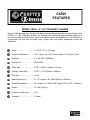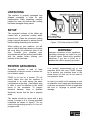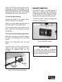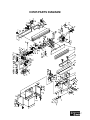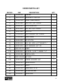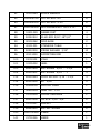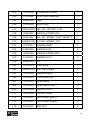
1
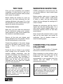
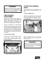
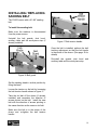
CX505 6” x 89” EDGE BELT SANDER User Manual TABLE OF CONTENTS General Safety Instructions .......................................................................... 3 Specific Safety Instructions........................................................................... 4 Features ....................................................................................................... 5 Physical Features ......................................................................................... 6 Unpacking .................................................................................................... 7 Setup ............................................................................................................ 7 Proper Grounding ......................................................................................... 7 Assembly ...................................................................................................... 8 Stand ............................................................................................................ 8 Installing the Sander Onto the Stand............................................................ 8 Motor Drum Guard........................................................................................ 9 Fence ........................................................................................................... 9 Auxiliary Table .............................................................................................. 9 Work-piece Stop ...........................................................................................10 Belt Tracking.................................................................................................10 ON/OFF Switch ............................................................................................11 Test Run .......................................................................................................12 Work-piece Inspection ..................................................................................12 Connecting to a Dust Collector .....................................................................12 Table Height Adjustment ..............................................................................13 Tilting the Sanding Head ..............................................................................13 Installing/Replacing the Sanding Belt ...........................................................14 Maintenance .................................................................................................15 Cleaning .......................................................................................................15 Lubrication ....................................................................................................15 Troubleshooting............................................................................................16 Parts Diagram...............................................................................................17 Parts List ......................................................................................................18 Warranty .......................................................................................................24 2 GENERAL SAFETY INSTRUCTIONS Extreme caution should be used when operating all power tools. Know your power tool, be familiar with its operation, read through the owner’s manual and practice safe usage procedures at all times. ALWAYS read and understand the user manual before operating the machine. router bits, shaper heads, blades, knives or making other adjustments or repairs. CONNECT your machine ONLY to the matched and specific power source. NEVER leave a tool unattended while it is in operation. ALWAYS wear safety glasses respirators, hearing protection and safety shoes, when operating your machine. NEVER reach over the table when the tool is in operation. DO NOT wear loose clothing or jewelry when operating your machine. A SAFE ENVIRONMENT is important. Keep the area free of dust, dirt and other debris in the immediate vicinity of your machine. BE ALERT! DO NOT use prescription or other drugs that may affect your ability or judgment to safely use your machine. DISCONNECT the power source when changing drill bits, hollow chisels, ALWAYS keep blades, knives and bits sharpened and properly aligned. ALL OPERATIONS MUST BE performed with the guards in place to ensure safety. ALWAYS use push sticks and feather boards to safely feed your work through the machine. ALWAYS make sure that any tools used for adjustments are removed before operating the machine. ALWAYS keep the bystanders safely away while the machine is in operation. 3 CX505 – 6” x 89” EDGE BELT SANDER SPECIFIC SAFETY INSTRUCTIONS MAKE SURE the sander is connected to the matched and specific power source instructed in the manual. ALL THE GUARDS must be in place while operating the sander to ensure safety. MAKE SURE before making any adjustments, the switch is in the “OFF” position and the cord is un-plugged from the power source. NEVER sand more than one work piece at a time on this sander. ALWAYS wear a dust mask and safety glasses while operating the sander. The tiny dust particles produced by the sander can cause serious health problems. ALWAYS inspect stock for staples, nails knots or any other foreign material before sanding. ALWAYS operate the sander in a wellventilated area and use a dust collection system for dust removal whenever possible. DO NOT wear loose clothing and jewelry while operating this sander. ALWAYS hold the work piece firmly when sanding. When not using the table, i.e. sanding free-hand, grip the work piece with both hands. KEEP YOUR WORK AREA CLEAN. Cluttered areas and workbenches increase the chance of accident. USE THE STOP FENCE when performing horizontal sanding on the belt sander. NEVER LEAVE the sander unattended while it is running. MAINTAIN AND SERVICE your sander regularly as instructed in the user manual. KEEP CHILDREN AWAY. All visitors should be kept at a safe distance from the work area. DO NOT force the sander. It will do the job better and will be safer at the operating rate for which it is designed. MAKE SURE you have read and understood all the safety instructions in the manual and you are familiar with your CX505 sander, before operating it. If you fail to do so, serious injury could occur. WARNING The safety instructions given above can not be complete because the environment in every shop is different. Always consider safety first as it applies to your individual working conditions. 4 CX505 FEATURES MODEL CX505 – 6” x 89” EDGE BELT SANDER As part of the growing line of Craftex CX-Series woodworking equipment, we are proud to offer CX505 a 6” x 89” Edge Belt Sander. By following the instructions and procedures laid out in this user manual, you will receive years of excellent service and satisfaction. The CX505 is a professional tool and like all power tools, proper care and safety procedures should be adhered to. Motor ................................... 1-1/2 HP, 110 V, 18 Amps Length of Oscillation ............ 1/8” (3.2mm) Up, 1/8” (3.2mm) Down, 1/4" (6.4mm) Total Belt Size .............................. 6” x 89” (152 x 2260mm) Belt Speed ........................... 3450 RPM Table Size............................ 9-7/8” x 29-5/8” (250mm x 751mm) Auxiliary Table Size ............. 9-7/8” x 11-78 (250mm x 300mm) Dust Port.............................. One 4” Base Dimensions................. 21-1/2” Length x 49” Width (546mm x 432mm) Overall Dimensions ............. 50” Length x 21” Width x 49” Height (1270 x 533 x 1245mm) Weight ................................. 277 lbs (126 Kg) Powder Coated Paint........... Yes Warranty .............................. 3 Years 5 CX505 – EDGE BELT SANDER PHYSICAL FEATURES Belt Guard Belt Tension Lever 6” x 48” Sanding Belt Dust Hood Lock Knobs Fence Lock Knobs Motor Drum Guard Fence Work Table 4” Dust Hood Sanding Head Tilt Lock Knob 1-1/2 HP Motor Cabinet Door Lock ON/OFF Switch Cabinet Door Cabinet Powdered Coated Paint 6 UNPACKING The machine is properly packaged and shipped completely in crate for safe transportation. When unpacking, carefully inspect the crate and ensure that nothing has been damaged during transit. SETUP The unpainted surfaces of the tables are coated with a protective coating which prevents rust. Clean this protective coating using a rag with kerosene or painter thinner before starting assembling the machine. When setting up your machine, you will want to find an ideal spot where your planer will most likely be positioned most of the time. Consider your complete work environment as well as working comfortable with the sander before placing your machine in the ideal spot. Figure-1 110-Volts outlet for CX505 WARNING! Improper connection of the equipmentgrounding conductor can result in a risk of electric shock. Check with a qualified electrician if you are in doubt as to whether the outlet is properly grounded. PROPER GROUNDING Grounding provides a path of least resistance for electric current to reduce the risk of electric shock. CX505 is for use on a normal 110 volt circuit. Make sure that the machine is connected to an outlet having the same configuration as the plug. If an adaptor plug is used, it must be attached to the metal screw of the receptacle. To prevent electrical hazards, have a qualified electrician ensure that the line is properly wired. It is strongly recommended not to use extension cords with your CX505. Always try to position your machine close to the power source so that you do not need to use extension cords. In case if you really find it necessary to use an extension cord, make sure the extension cord does not exceed 50-feet in length and the cord is 14-gauge to prevent motor damage. The sander should be wired with a plug having 3 prongs to fit a 3 prong grounded receptacle as shown in figure-1. Do not remove the grounding prong to fit it into a 2 pronged outlet. 7 ASSEMBLY Assembling the CX505 edge belt sander is simple and easy. To assemble the machine, follow the instructions given below. STAND Attach the side brackets to the front and rear brackets as shown in figure-2 using screws and washers and lock washers provided. Do not tighten the screws. Attach the brackets together as shown in figure-2 using screws, washers and lock washers provided. Make sure the stand is sitting level on the floor from all four sides and tighten the screws. Figure-3 Installing the bottom plate INSTALLING THE SANDER ONTO THE STAND Once the stand is completely assembled and all the screws are tightened properly, use a fork lift or get the help of an assistant and lift the sander onto the stand. Make sure the two holes on the side of the sander is aligned with the two holes on the stand. Figure-2 Assembling the stand Slide the stand bottom plate from the top into the stand assembly and install it as shown in figure-3. Secure it to the side brackets using two screws and two washers provided. Figure-4 Installing the sander onto the stand Open the stand door and secure the sander onto the stand from inside using screws, washer and lock washers provided. See figure-5. 8 FENCE Slide two T-nuts into the T-slot on the table and place the fence on the table aligning the two slots on the fence with the two holes on the T-nuts. Secure fence to the table using washers and lock knobs. Figure-5 Securing the sander onto the stand from inside the cabinet WARNING! The CX505 is a heavy machine. Do not over-exert yourself. Get the help of an assistant when lifting the sanding head onto the stand. Figure-7 Installing the fence AUXILIARY TABLE MOTOR DRUM GUARD Install the motor drum guard to the dust hood as shown in figure-6 using screws provided. The auxiliary table is installed on the right side of the sander when sanding round or curved work-pieces. To install the auxiliary table: Move the dust hood out of the way by loosening the knobs holding it in position. Move the dust hood to the back and retighten the knob to hold it in position as shown in figure-8. Figure-6 Installing the motor drum guard Figure-8 Moving the dust hood away 9 Insert the rod into the hole as shown in figure-9 making sure that the flat surface of the rod is facing the hole on the bracket. Use the knob provided, and secure the rod in position. IMPORTANT The dust hood can not be properly closed when the table is installed on the sander. In order to use dust hood with your sander, uninstall the table whenever the table is not being used. WORKPIECE STOP Loosen the knob securing the dust hood in position and move the dust hood out of the way. Re-tighten the knob to hold the dust hood in position. Figure-9 Securing the table rod into the hole Position the table with the hole at the back of the table onto the rod and secure it by tightening the screw and then the nut shown in figure-10. Take the work-piece stop and install it by inserting the shaft on the work-piece stop into the hole. Use a flat washer and a long knob securing the work-piece stop onto the sander. See figure-11. Figure-11 Installing the work-piece stop Figure-10 Installing the table onto the rod The table is used with CX505 only when the table is in vertical position. BELT TRACKING Belt tracking means where the belt rides on the drums. The belt should always be centered on both drums. 10 Proper belt tracking prolongs the belt life, preventing the belt from slipping off the drums during operation. The belt tracking is adjusted by tilting the idler drum slightly towards the front or rear of the machine. ON/OFF SWITCH To check the belt tracking: The ON/OFF switch on CX505 features a safety key to prevent from accidental or unauthorized operations. When the sander is not in use for a long period of time, simply insert the safety key into the switch. Connect the sander to the power source and turn it ON for 4 to 5 seconds. To start the sander, remove the safety key and push the ON button in. Observe carefully where the belt rides on the drums and turn the machine OFF. The belt should always be centered on the drum. If the belt is not centered it needs to be adjusted. To perform the belt tracking adjustment: Make sure the switch is in the OFF position the cord is disconnected from the power source. Remove the work-piece stop and dust hood. Loosen the lock nut and turn the adjustment screw a few turns clockwise or anticlockwise as needed using the tool provided. Figure-13 ON/OFF switch IMPORTANT To prevent any type of accidental injuries, make sure the power switch is in the OFF position before connecting the sander to the power source. Figure-12 Belt tracking adjustment 11 TEST RUN Once you have assembled your machine completely, it is then time for a test run to make sure that the machine works properly and is ready for operation. Before starting the sander for a test run make sure you have performed the belt tracking adjustment (see page-10) so that the belt does not come off the drums or jam against the sander during startup. To test run the sander: Make sure you have read and understood all the instructions given in the manual, safety features on your CX505 sander and the machine is assembled properly. Remove all the tools and objects used during assembly from the machine. Ensure the belt tracks properly on the drums. Connect the machine to the power source and turn it ON and be ready to turn it OFF quickly if there is any problem during startup. During the test run if there is any unusual noise coming from the machine or the machine vibrates excessively, stop the machine immediately and disconnect from the power source and investigate to determine the problem with your machine. Make sure all the nuts and bolts are tightened and all the parts are installed properly during assembly. WORKPIECE INSPECTION CX505 is designed to sand wood only. Do not use this machine to sand metals, glass or stone etc. Before sanding, make sure to inspect the work-piece for nails, staples, small pieces of stone or metal, and any other foreign objects that can damage the sanding belt if come in contact Sanding the work-piece with this kind of objects can tear the sanding paper. For a safe cutting method always inspect your work-piece carefully before cut and wear eye protection. Some woods with excessive finish or glue load up the sand paper and reduce its usefulness. Use an abrasive cleaner to clean the sanding paper. CONNECTING TO A DUST COLLECTOR The CX505 is equipped with a 4” diameter dust hood to connect to a dust collector. When connecting to a dust collector, use a proper sized hose and make sure all the connections are sealed tightly. It is recommended to use a proper sized dust collector with the CX505 to ensure adequate dust collection. WARNING! WARNING! Before starting the sander, make sure that you have read and understood the manual and you are familiar with the functions and safety features on this machine. Failure to do so may cause serious personal injury. The saw dust produced by the band saw can go into your lungs and cause serious health problems. Make sure the band saw is connected to a dust collection system while operating it. 12 WARNING! Make sure the machine’s power switch is off and the cord is disconnected from the power source when installing/removing any part or servicing the sander. TILTING THE SANDING HEAD The sanding head can be adjusted to any angle from 90° to 180° as required for your job. To tilt the sanding head: TABLE HEIGHT ADJUSTMENT The table on CX505 can be adjusted to different heights. Table height adjustment allows using different portions of the sanding belt surface while sanding and results in even wearing of the sanding belt. Unlock the sanding head by loosening the lock lever under the head shown in figure15. Tilt the head to the required angle on the head tilt scale. The belt on CX505 is 6” in width. When sanding a 3” tall work-piece, for the first half you can adjust the table height and use the lower portion of the sanding belt while for the second half you can adjust the table using the upper portion of the sanding belt. This maximizes the sanding belt usage on you sander. Figure-15 Sanding head tilt scale To adjust the table height: Loosen the two lock knobs shown in figure14 and lower or raise the table to your desired height. Tighten the knobs and lock the table in position. Once the sanding head is in the desired angle, pull the lock lever and secure the head in position. WARNING! Make sure to lock the dust hood in position before tilting the sanding head so that the dust hood does not scratch the body of the sander. Figure-14 Table height lock knobs 13 INSTALLING / REPLACING SANDING BELT The CX505 comes with a 6”x 89” sanding belt. To install the sanding belt: Make sure the machine is disconnected from the power source. Uninstall the belt guards, dust hood, auxiliary table and the work-piece stop (if already installed). Figure-17 Belt tension handle Once the belt is installed, perform the belt tracking adjustment so that the belt tracks in the center of the drums. (See page-10 for details) Re-install the guards, dust hood and auxiliary table and the work-piece stop. Figure-16 Belt guard Set the sanding head in vertical position by tilting the head. Loosen the tension on the belt by loosening the belt tension handle shown in figure-17. Take the old belt off the drums (if already installed) and remember the direction of arrows printed on the belt. Install the new belt with the direction of arrows pointing to the same direction as the ones on old belt. Make sure the belt is in the center of the drums and re-tighten the belt tension handle. 14 MAINTENANCE During the life of your machine, you will need to practice some regular maintenance to keep your sander in peak performance condition. WARNING! Make sure the machine’s power switch is OFF and the cord is disconnected from the power source when installing / removing any part or servicing the sander. Check your machine daily for the following before use: CLEANING The moisture from the wood dust remaining on the table surface can cause rust. The table and other unpainted surfaces of the machine should be cleaned and wiped after every use to make sure there is no moisture against bare metal surfaces. LUBRICATION Lubricate the belt tension assembly and the oscillating drum assembly once in 6 months using a small amount of all purpose grease. All the bearings in the motor housing and drums are lubricated and do not require any lubrication. Damaged or worn sanding belt Damaged or worn power cord Loose mounting nuts, bolts, and parts Any other unsafe condition 15 TROUBLESHOOTING TROUBLE Motor doesn’t start. Sanding belt slips. Machine vibrates excessively. CAUSES 1. No electricity. 2. Defective switch, motor or cord. 3. Overload has reacted. 1. Sanding belt is stretched. 2. Too much applied pressure. 1. Stand on uneven floor. 2. Motor mounts are loose. Abrasive belt keeps tearing. 1. Belt is running the wrong direction. Sanded edge not square. 1. Table not square to sanding platen. Sanding marks on the wood. 1. Work piece was held still. 2. Wrong grit sanding belt. 3. Feed pressure too high. CORRECTION 1. Check mains and fuse. 2. Consult an electrician. 3. Wait and reset overload cut-off. 1. Install new sanding belt. 2. Move work piece while sanding. 1. Adjust stand for even support. 2. Tighten motor mount belts. 1. Observe arrow on the sanding belt. 1. Adjust positive stop for 90°. 1. Keep work piece moving. 2. Use coarser grit for stock removal and fine grit for finish sanding. 3. Never force the wood. 16 CX505 PARTS DIAGRAM 17 CX505 PARTS LIST REF NO. IVM 1 20101001 CABINET 1 2 W0000006 MAGANETIC SWITCH 1 8 20101005 WORK TABLE BRACK 1 9 S0120380 LOCK NUT 3/8"-16UNC 1 10 20101007 CAM ECCENTRIC 1 10A S0110600 HEX. NUT 3/8"-16UNC 1 11 S0310525 PIN 5*25 1 12 10102024 LOCK HANDLE 3/8"-16UNC 1 13 10102023 HAND KNOB 1 14 S0400525 KEY 5*5*25 1 15 S0020416 HEX. HD. SCR. 1/4"*20UNC*1" 1 16 S0210404 FLAT WASHER 1/4"*23 5 17 DESCRIPTION 20101011A TABLE QTY 1 17A S0020510 CAP SCR. 5/16" * 18UNC * 1" 4 18 20101065 SPECIAL SCR. 2 19 S0111000M NUT M10 2 19A S0230308 SPRING WASHER 3/8" 2 20 20101013 GUIDE BLOCK 2 21 20101014 FENCE 1 22 20101015 KNOB BOLT 8*12 4 23 20101016 MOTOR ROLLER 1 24 20102017 GUIDE BAR 1 18 25 S0310306 PIN 3*6 1 26 S0050404 SET SCR. 1/4"*20UNC*1/4" 1 27 10104049Q POSITION PLATE 1 28 10104050 POINTER 1 28A 20102020 LOCKING NUT 1 29 20101022 SANDING BELT 1 30 10104046 MITER GAUGE BODY 1 31 S0030108 RD.HD.SCR. 5/32"*32UNC*1/2" 3 32 S0110100 HEX.NUT 5/32"-32UNC 3 33 10104045 HAND KNOB 1 34 21700001 SANDING TABLE 1 34B 21700002 SANDING TABLE STAND 1 35 21700037 ARBOR 1 36 20101039 KNOB BOLT 8*35 1 37A S0310640 PIN 6*40 1 38 21700004 SPRING 6*40 1 39 20101055 PARTITION RING 1 41 21700005 MOTOR ROLLER BRACKET 1 43 21700052 ROLLER COVER 2 47 47A 20103029C MICRO-ADJUST SCREW 1 20103029A MICRO-ADJUST NUT 1 48 21700049 RUGULATING PLATE 1 49 S0030304 PHILIP HD SCR. 3/16"*24UNC*1/4" 4 50 S0220300 GEAR WASHER 3/16" 10 19 51 20101031 BELT REPLACING PLATE 1 54 20101032a SAND CLAMP HANDLE 1 55 S0020530 HD.HEX.SCR. 5/16"*18UNC*1-3/4" 1 56 S0120201 NYLON NUT 5/16"-18UNC 5 57 20101033 TILT SCALE 1 58 S0040301c FLAT HD.SCR. 3/16*3/4 1 59 10102022 WIDTH POINTER 1 60 S0040300 FLAT HD.SCR. 3/16"*24UNC*3/8" 1 61 M0000000 MOTOR 1 62 S0020520 HD.HEX.SCR 5/16"*18UNC*1-1/4" 5 63 S0210500 FLAT WASHER 8.5"*16*2T 5/16" 67 L0000154a ELECTRIC CORD 1 69B 21700039 BELT COVER 1 69N 21700013 DUST COVER 1 70 20101002 LIFTING PLATE 2 71 20101024 KNOB BOLT 8*20 3 72 20101040 BRACKET 1 73 20104054 STAND (RIGHT & RIGHT) 2 74 20104053 PARTITION 2 75 20104060G DOOR 40 1 77 S0211223 FLAT WASHER #12 78 S0230506 SPRING WASHER 22 79 S0110500 HD. HEX. SCR. 5/16"-18UNC 24 80 21700045A FLEXIBLE PLATE 2 2 20 81 20103044 DRIVER WRENCH 1 82 S0040512M FLAT HD.SCR. M5 8 83 S0040420M FLAT HD.SCR. 4*20 8 87 S0121400M ANTI-LOOSEN NUT M14*2.0P 1 88 10401029 RUBBER FEET 4 89 S0090512 RD.HD.SCR 5/16"-18*3/4" 4 90 90100062 FIXED BASE 2 94 20101051 EXTENSION TABLE 1 95 S0230300 SPRING WASHER 3/16" 96 20101050 SUPPORTING ROD 1 100 J0000102 SCALE 1 101 10105052 LABEL 1 103 S0010505 HEX. SCREW 5/16" * 1-1/4" 2 104 S0030501 HEX. SCREW 5/16" * 1" 4 112 S0030324 PHILIP HD SCR. 3/16"*1-1/2" 3 114 S0110300 NUT 3/16" 5 115 L0000005 ELECTRIC CORD 1 117 50203004 KNOB M6 * P1.0 2 136 21700018 SUPPORTING BASE 1 137 S0010308 CAP SCR. 3/16"*3/8" 2 138 21700027 BRACKET 1 139 S0020412 HEX. HD. SCREW 2 140 141 S0070306M SCREW 21700026 ARBOR 10 1 1 21 143 21700029 EXTENSION SPRING 1 144 C1100698 SMALL BALL BEARING 3 145 S0520008 RING 1 146 21700025 FIXED LOOP 2 S0010520M SOC. HD. CAP SCR. 5*20 4 147 148 20900049 BEARING COVER 6202 1 149 S0020501 HEX. HD. SCREW 5/16"*18UNC*1" 1 150 S0040412M FLAT HD. SCREW 4*12 3 151 21700017 BEARING BASE 1 152 C1206202 BEARING 6202 1 154 20900049 BEARING COVER 6202 1 155 C1106003 BEARING 6003 1 159 S0400430 KEY 1 161 21700015 FIXED BASE 1 162 S0010510M HEX. CAP SCREW 5 163 21700036 BEARING BUSH 2 165 21700021 CAM ECCENTRIC 1 167 21700010 WORM GEAR 1 168 21700020 WORM GEAR SHAFT 1 169 20101048A GRAPHITE PAD 1 170 21700016 SUPPORT SHAFT 2 173 21700011 DUST HOOD (LEFT) 1 175 21700012 DUST HOOD (RIGHT) 1 178 S0120200 LOCK NUT 2 22 179 21700051 ROLLER ARBOR 1 183 21700008 DRIVEN ROLLER 1 184 S0050606M SOC.SET.SCR. 6*6 2 186 S0400540 KEY 5*5*40 1 188 21700009 WORM 1 189 191 S0210300a FLAT WASHER 3/16" S0400425 KEY 4*4*25 1 1 192 S0230500M SPRING WASHER 193 W1017W-2 STRAIN RELIEF BUSHING 2 194 21700032 JOING PLATE 1 195 21700033 SPRING BUCKLE SHAFT 1 196 21700038K DUST COLLECTION 11 1 202 21700053 SPONGE 1 203 21700054 SPONGE PIECE 1 204 S0300845 CAP SCREW 5/16"*18UNC*1-3/4" 2 205 90100008a PLATY SPRING 2 23 WARRANTY CRAFTEX 3 YEARS LIMITED WARRANTY Craftex warrants every product to be free from defects in materials and agrees to correct such defects where applicable. This warranty covers three years for parts and 90 days for labour (unless specified otherwise), to the original purchaser from the date of purchase but does not apply to malfunctions arising directly or indirectly from misuse, abuse, improper installation or assembly, negligence, accidents, repairs or alterations or lack of maintenance. Proof of purchase is necessary. All warranty claims are subject to inspection of such products or part thereof and Craftex reserves the right to inspect any returned item before a refund or replacement may be issued. This warranty shall not apply to consumable products such as blades, bits, belts, cutters, chisels, punches etceteras. Craftex shall in no event be liable for injuries, accidental or otherwise, death to persons or damage to property or for incidental contingent, special or consequential damages arising from the use of our products. RETURNS, REPAIRS AND REPLACEMENTS To return, repair, or replace a Craftex product, you must visit the appropriate Busy Bee Tools showroom or call 1800-461-BUSY. Craftex is a brand of equipment that is exclusive to Busy Bee Tools. For replacement parts directly from Busy Bee Tools, for this machine, please call 1-800-461-BUSY (2879), and have your credit card and part number handy. All returned merchandise will be subject to a minimum charge of 15% for re-stocking and handling with the following qualifications. Returns must be pre-authorized by us in writing. We do not accept collect shipments. Items returned for warranty purposes must be insured and shipped pre-paid to the nearest warehouse Returns must be accompanied with a copy of your original invoice as proof of purchase. Returns must be in an un-used condition and shipped in their original packaging a letter explaining your reason for the return. Incurred shipping and handling charges are not refundable. Busy Bee will repair or replace the item at our discretion and subject to our inspection. Repaired or replaced items will be returned to you pre-paid by our choice of carriers. Busy Bee reserves the right to refuse reimbursement or repairs or replacement if a third party without our prior authorization has carried out repairs to the item. Repairs made by Busy Bee are warranted for 30 days on parts and labour. Any unforeseen repair charges will be reported to you for acceptance prior to making the repairs. The Busy Bee Parts & Service Departments are fully equipped to do repairs on all products purchased from us with the exception of some products that require the return to their authorized repair depots. A Busy Bee representative will provide you with the necessary information to have this done. For faster service it is advisable to contact the nearest Busy Bee location for parts availability prior to bringing your product in for repair. 24