1
75000 SERIES B
Mainframes
E1300B and E1301B
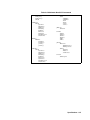
User’s Manual
Copyright © Agilent Technologies, Inc., 1989, 1990, 1991, 2006
Manual Part Number: E1300-90005
Microfiche Part Number: E1300-99005
Printed: September 2012
Printed in Malaysia
Edition 3
E 0912
Certification
Agilent Technologies certifies that this product met its published specifications at the time of shipment from the factory. Agilent Technologies further certifies that its calibration measurements are traceable to the United States National Institute of Standards and Technology (formerly National Bureau of Standards), to the extent allowed by that organization’s calibration facility, and to the calibration
facilities of other International Standards Organization members.
Warranty
This Agilent Technologies product is warranted against defects in materials and workmanship for a period of three years from date of
shipment. Duration and conditions of warranty for this product may be superseded when the product is integrated into (becomes a part
of) other Agilent products. During the warranty period, Agilent Technologies will, at its option, either repair or replace products which
prove to be defective.
For warranty service or repair, this product must be returned to a service facility designated by Agilent Technologies. Buyer shall prepay shipping charges to Agilent and Agilent shall pay shipping charges to return the product to Buyer. However, Buyer shall pay all
shipping charges, duties, and taxes for products returned to Agilent from another country.
Agilent warrants that its software and firmware designated by Agilent for use with a product will execute its programming instructions
when properly installed on that product. Agilent does not warrant that the operation of the product, or software, or firmware will be uninterrupted or error free.
Limitation Of Warranty
The foregoing warranty shall not apply to defects resulting from improper or inadequate maintenance by Buyer, Buyer-supplied products or interfacing, unauthorized modification or misuse, operation outside of the environmental specifications for the product, or improper site preparation or maintenance.
The design and implementation of any circuit on this product is the sole responsibility of the Buyer. Agilent does not warrant the
Buyer’s circuitry or malfunctions of Agilent products that result from the Buyer’s circuitry. In addition, Agilent does not warrant any
damage that occurs as a result of the Buyer’s circuit or any defects that result from Buyer-supplied products.
NO OTHER WARRANTY IS EXPRESSED OR IMPLIED. Agilent SPECIFICALLY DISCLAIMS THE IMPLIED WARRANTIES
OF MERCHANTABILITY AND FITNESS FOR A PARTICULAR PURPOSE.
Exclusive Remedies
THE REMEDIES PROVIDED HEREIN ARE BUYER’S SOLE AND EXCLUSIVE REMEDIES. Agilent SHALL NOT BE LIABLE
FOR ANY DIRECT, INDIRECT, SPECIAL, INCIDENTAL, OR CONSEQUENTIAL DAMAGES, WHETHER BASED ON CONTRACT, TORT, OR ANY OTHER LEGAL THEORY.
Notice
The information contained in this document is subject to change without notice. Agilent Technologies MAKES NO WARRANTY OF
ANY KIND WITH REGARD TO THIS MATERIAL, INCLUDING, BUT NOT LIMITED TO, THE IMPLIED WARRANTIES OF
MERCHANTABILITY AND FITNESS FOR A PARTICULAR PURPOSE. Agilent shall not be liable for errors contained herein or
for incidental or consequential damages in connection with the furnishing, performance or use of this material. This document contains
proprietary information which is protected by copyright. All rights are reserved. No part of this document may be photocopied, reproduced, or translated to another language without the prior written consent of Agilent Technologies, Inc. Agilent assumes no responsibility for the use or reliability of its software on equipment that is not furnished by Agilent.
U.S. Government Restricted Rights
The Software and Documentation have been developed entirely at private expense. They are delivered and licensed as "commercial
computer software" as defined in DFARS 252.227- 7013 (Oct 1988), DFARS 252.211-7015 (May 1991) or DFARS 252.227-7014 (Jun
1995), as a "commercial item" as defined in FAR 2.101(a), or as "Restricted computer software" as defined in FAR 52.227-19 (Jun
1987)(or any equivalent agency regulation or contract clause), whichever is applicable. You have only those rights provided for such
Software and Documentation by the applicable FAR or DFARS clause or the Agilent standard software agreement for the product involved.
Agilent E1300B and E1301B Mainframes Service Manual
Edition 3 Rev 3
Copyright © 1992-2006 Agilent Technologies, Inc. All Rights Reserved.
i
Printing History
The Printing History shown below lists all Editions and Updates of this manual and the printing date(s). The first printing of the manual is Edition 1. The Edition number increments by 1 whenever the manual is revised. Updates, which are issued between Editions,
contain replacement pages to correct the current Edition of the manual. Updates are numbered sequentially starting with Update 1.
When a new Edition is created, it contains all the Update information for the previous Edition. Each new Edition or Update also includes a revised copy of this printing history page. Many product updates or revisions do not require manual changes and, conversely,
manual corrections may be done without accompanying product changes. Therefore, do not expect a one-to-one correspondence between product updates and manual updates.
Edition 3 Rev 3 . . . . . . . . . . September 2012
Edition 1 (Part Number E1300-90001). . . . . . . . . . October 1989
Edition 2 (Part Number E1300-90002). . . . . . . . . . September 1990
Edition 3 (Part Number E1300-90005). . . . . . . . . . November 1991
Edition 3 Rev 2 (Part Number E1300-90005) . .. . February 2006
Trademark Information
Microsoft® and MS-DOS® are U.S. registered trademarks of Microsoft Corporation. IBM® and PC-DOS® are U.S. registered trademarks of International Business Machines Corporation. DEC® , VT100® , and VT220® are registered trademarks of Digital Equipment Corporation. WYSE® is a registered trademark or Wyse Technology. WY-30 is a trademark of Wyse Technology.
Macintosh® is a registered trademark of Apple Computer Inc.
Safety Symbols
Instruction manual symbol affixed to product. Indicates that the user must refer to the
manual for specific WARNING or CAUTION information to avoid personal injury
or damage to the product.
Alternating current (AC).
Direct current (DC).
Indicates hazardous voltages.
Indicates the field wiring terminal that must
be connected to earth ground before operating the equipment—protects against electrical shock in case of fault.
or
Frame or chassis ground terminal—typically connects to the equipment’s metal
frame.
WARNING
Calls attention to a procedure, practice, or
condition that could cause bodily injury or
death.
CAUTION
Calls attention to a procedure, practice, or condition that could possibly cause damage to
equipment or permanent loss of data.
WARNINGS
The following general safety precautions must be observed during all phases of operation, service, and repair of this product.
Failure to comply with these precautions or with specific warnings elsewhere in this manual violates safety standards of design,
manufacture, and intended use of the product. Agilent Technologies assumes no liability for the customer’s failure to comply
with these requirements.
Ground the equipment: For Safety Class 1 equipment (equipment having a protective earth terminal), an uninterruptible safety earth
ground must be provided from the mains power source to the product input wiring terminals or supplied power cable.
DO NOT operate the product in an explosive atmosphere or in the presence of flammable gases or fumes.
For continued protection against fire, replace the line fuse(s) only with fuse(s) of the same voltage and current rating and type.
DO NOT use repaired fuses or short-circuited fuse holders.
Keep away from live circuits: Operating personnel must not remove equipment covers or shields. Procedures involving the removal
of covers or shields are for use by service-trained personnel only. Under certain conditions, dangerous voltages may exist even with the
equipment switched off. To avoid dangerous electrical shock, DO NOT perform procedures involving cover or shield removal unless
you are qualified to do so.
DO NOT operate damaged equipment: Whenever it is possible that the safety protection features built into this product have been impaired, either through physical damage, excessive moisture, or any other reason, REMOVE POWER and do not use the product until
safe operation can be verified by service-trained personnel. If necessary, return the product to an Agilent Technologies Sales and Service Office for service and repair to ensure that safety features are maintained.
DO NOT service or adjust alone: Do not attempt internal service or adjustment unless another person, capable of rendering first aid
and resuscitation, is present.
DO NOT substitute parts or modify equipment: Because of the danger of introducing additional hazards, do not install substitute
parts or perform any unauthorized modification to the product. Return the product to an Agilent Technologies Sales and Service Office
for service and repair to ensure that safety features are maintained.
ii
Declaration of Conformity
Declarations of Conformity for this product and for other Agilent products may be downloaded from the Internet. There are two methods to obtain
the Declaration of Conformity:
•
Go to http://regulations.corporate.agilent.com/DoC/search.htm . You can then search by product number to find the latest Declaration
of Conformity.
• Alternately, you can go to the product web page (www.agilent.com/find/E1300B), click on the Document Library tab then
scroll down until you find the Declaration of Conformity link.
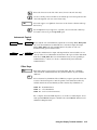
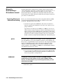
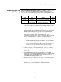
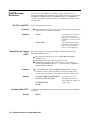
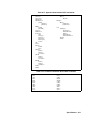
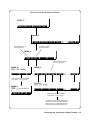
Agilent 75000 Series B Documentation
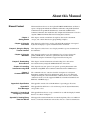
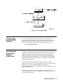
Manual Descriptions
Installation and Getting Started Guide. Contains step-by-step instructions for
all aspects of plug-in module and mainframe installation. This guide also
contains introductory programming information and examples.
Agilent E1300B/E1301B Mainframe User’s Manual. Contains programming
information for the mainframe, front panel operation information (for the
Agilent E1301B mainframe), and general programming information for
instruments installed in the mainframe.
Plug-In Module User’s Manuals. Contains plug-in module programming and
configuration information. These manuals contains examples for the most-used
module functions, and a complete TMSL command reference for the plug-in
module.
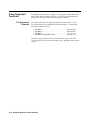
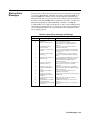
Installation and Getting
Started Guide
Instrument Applications*
Plug-in Module User’s
Manuals
Using the Mainframe front panel or pacer
Mainframe User’s
Manuals
* For Scanning Voltmeter Applications, refer to the Agilent E1326A/E1411A 5 1/2 Digit
Multimeter User’s Manual.
Suggested Sequence for Using the Manuals
iv
1
Related Documents
Agilent Instrument BASIC User’s Handbook. Includes three books: Agilent
Instrument BASIC Programming Techniques , Agilent Instrument BASIC
Interfacing Techniques, and Agilent Instrument BASIC Language Reference.
Using Agilent Instrument BASIC with the E1405. Contains information on the
version of Agilent Instrument Basic which can be installed in ROM in your
E1405B Command Module.
Beginner’s Guide to SCPI. Explains the fundamentals of programming
instruments with Standard Commands for Programmable Instruments (SCPI).
We recommend this guide to anyone who is programming with TMSL for the
first time.
Tutorial Description of the General Purpose Interface Bus. Describes the
technical fundamentals of the General Purpose Interface Bus (GPIB). This
book also includes general information on IEEE 488.2 Common Commands.
We recommend this book to anyone who is programming with IEEE 488.2 for
the first time.
IEEE Standard 488.2-1987, IEEE Standard Codes, Formats, Protocols, and
Common Commands. Describes the underlying message formats and data types
used in TMSL and defines Common Commands. You may find this document
useful if you need to know the precise definition of certain message formats,
data types, or Common Commands. Available from: The Institute of Electrical
and Electronic Engineers, Inc.; 345 East 47th Street;
New York, NY 10017; USA
VXIbus System Specifications. Agilent part number E1400-90006.
The VMEbus Specification. Available from: VMEbus International Trade
Association; 10229 N. Scottsdale Road, Suite E; Scottsdale, AZ 85253; U.S.A.
v
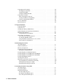
About this Manual
Manual Content
Chapter 1:
Getting Started
Chapter 2: Using the
Front Panel
Chapter 3: Using the Display
Terminal Interface
Chapter 4: Using the
Mainframe
This manual shows how to use the Agilent E1300/E1301 Mainframe and how to
operate and program instruments within the mainframe using SCPI (Standard
Commands for Programmable Instruments) commands and IEEE 488.2
Common Commands. For installation and configuration information refer to the
"Agilent 75000 Series B Installation and Getting Started Guide".
This chapter contains a mainframe description, discusses the instrument
concept, and contains introductory programming examples.
This chapter describes how to use the Agilent E1301 mainframe’s front panel
keyboard and display to operate instruments in the mainframe.
This chapter describes how to use a display terminal to operate instruments in
the mainframe.
This chapter shows how to use the mainframe’s Pacer, how to change the
primary GPIB address, and how to synchronize internal and external
instruments using the mainframe’s Trigger In and Event Out ports.
Chapter 5: Downloading
Device Drivers
This chapter contains information on downloading device drivers into
non-volatile memory using both GPIB and RS-232 connections.
Chapter 6: Controlling
Instruments using GPIB
This chapter shows some general concepts for operating instruments in the
mainframe using IEEE 488.2 Common Commands and the GPIB interface.
Chapter 7:
Command Reference
Appendix A: Specification
Appendix B:
Error Messages
The command reference contains a detailed description of each System
Instrument command. It includes information on the choice of settings and
examples showing the context in which the command is used. It also contains
command references for the supported IEEE 488.2 Common Commands and
IEEE 488.1 GPIB Messages.
This appendix contains a list of the Mainframe’s operating specifications.
This appendix lists SCPI error codes and messages for the System Instrument,
and possible causes.
Appendix C: Connecting &
Configuring a Terminal
This appendix shows how to set-up a terminal for use with the Display Terminal
Interface described in Chapter 3.
Appendix D: Sending Binary
Data Over RS-232
This Appendix contains information on transferring binary files over an RS-232
interface. It includes information on how these files are coded for transmission.
vi
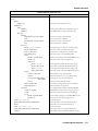
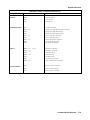
Table of Contents
1. Getting Started
Using This Chapter . . . . . . . . . .
Mainframe Description . . . . . . .
Optional Mainframe Memory . .
Instrument Definition . . . . . . . .
Instrument Logical Addresses .
Instrument Secondary Addresses
Unassigned Modules . . . . . . .
Introductory Programming Examples
.
.
.
.
.
.
.
.
.
.
.
.
.
.
.
.
.
.
.
.
.
.
.
.
.
.
.
.
.
.
.
.
.
.
.
.
.
.
.
.
.
.
.
.
.
.
.
.
.
.
.
.
.
.
.
.
.
.
.
.
.
.
.
.
.
.
.
.
.
.
.
.
.
.
.
.
.
.
.
.
.
.
.
.
.
.
.
.
.
.
.
.
.
.
.
.
.
.
.
.
.
.
.
.
.
.
.
.
.
.
.
.
.
.
.
.
.
.
.
.
.
.
.
.
.
.
.
.
.
.
.
.
.
.
.
.
.
.
.
.
.
.
.
.
.
.
.
.
.
.
.
.
.
.
.
.
.
.
.
.
.
.
.
.
.
.
.
.
.
.
.
.
.
.
.
.
.
.
.
.
.
.
.
.
.
.
.
.
.
.
.
.
.
.
.
.
.
.
.
.
.
.
.
.
.
.
.
.
.
.
.
.
.
.
.
.
1-1
1-1
1-1
1-3
1-4
1-4
1-4
1-4
Using this Chapter . . . . . . . . . . .
Front Panel Features . . . . . . . . . .
Using Menus . . . . . . . . . . . . . . .
A 60-Second Menu Tutorial . . . .
Using the System Instrument Menu
Using the Other Instrument Menus
Monitor Mode . . . . . . . . . . . .
Executing Commands . . . . . . . . . .
Editing . . . . . . . . . . . . . . . .
Key Descriptions . . . . . . . . . . . .
Menu Keys . . . . . . . . . . . . . .
Display Control & Editing Keys . .
Instrument Control Keys . . . . . .
Other Keys . . . . . . . . . . . . . .
In Case of Difficulty . . . . . . . . . . .
Instrument Menus . . . . . . . . . . . .
.
.
.
.
.
.
.
.
.
.
.
.
.
.
.
.
.
.
.
.
.
.
.
.
.
.
.
.
.
.
.
.
.
.
.
.
.
.
.
.
.
.
.
.
.
.
.
.
.
.
.
.
.
.
.
.
.
.
.
.
.
.
.
.
.
.
.
.
.
.
.
.
.
.
.
.
.
.
.
.
.
.
.
.
.
.
.
.
.
.
.
.
.
.
.
.
.
.
.
.
.
.
.
.
.
.
.
.
.
.
.
.
.
.
.
.
.
.
.
.
.
.
.
.
.
.
.
.
.
.
.
.
.
.
.
.
.
.
.
.
.
.
.
.
.
.
.
.
.
.
.
.
.
.
.
.
.
.
.
.
.
.
.
.
.
.
.
.
.
.
.
.
.
.
.
.
.
.
.
.
.
.
.
.
.
.
.
.
.
.
.
.
.
.
.
.
.
.
.
.
.
.
.
.
.
.
.
.
.
.
.
.
.
.
.
.
.
.
.
.
.
.
.
.
.
.
.
.
.
.
.
.
.
.
.
.
.
.
.
.
.
.
.
.
.
.
.
.
.
.
.
.
.
.
.
.
.
.
.
.
.
.
.
.
.
.
.
.
.
.
.
.
.
.
.
.
.
.
.
.
.
.
.
.
.
.
.
.
.
.
.
.
.
.
.
.
.
.
.
.
.
.
.
.
.
.
.
.
.
.
.
.
.
.
.
.
.
.
.
.
.
.
.
.
.
.
.
.
.
.
.
.
.
.
.
.
.
.
.
.
.
.
.
.
.
.
.
.
.
.
.
.
.
.
.
.
.
.
.
.
.
.
.
.
.
.
.
.
.
.
.
.
.
.
.
.
.
.
.
.
.
.
.
.
.
.
.
.
.
.
.
.
.
.
.
.
.
.
.
.
.
.
.
.
.
.
.
.
.
.
.
.
.
.
.
.
2-1
2-1
2-2
2-2
2-3
2-5
2-8
2-9
2-9
2-10
2-10
2-10
2-11
2-11
2-12
2-13
.
.
.
.
.
.
.
.
.
.
.
.
.
.
.
.
.
.
.
.
.
.
.
.
.
.
.
.
.
.
.
.
.
.
.
.
.
.
.
.
.
.
.
.
.
.
.
.
.
.
.
.
.
.
.
.
.
.
.
.
.
.
.
.
.
.
.
.
.
.
.
.
.
.
.
.
.
.
.
.
.
.
.
.
.
.
.
.
.
.
.
.
.
.
.
.
.
.
.
.
.
.
.
.
.
.
.
.
.
.
.
.
.
.
.
.
.
.
.
.
.
.
.
.
.
.
.
.
.
.
.
.
.
.
.
.
.
.
.
.
.
.
.
.
.
.
.
.
.
.
.
.
.
.
.
.
3-1
3-2
3-3
3-3
3-5
3-8
.
.
.
.
.
.
.
.
.
.
.
.
.
.
.
.
.
.
.
.
.
.
.
.
.
.
.
.
.
.
.
.
.
.
.
.
.
.
.
.
.
.
.
.
.
.
.
.
.
.
.
.
.
.
.
.
.
.
.
.
.
.
.
.
.
.
.
.
.
.
.
.
.
.
.
.
.
.
.
.
.
.
.
.
.
.
.
.
.
.
.
.
.
.
.
.
.
.
.
.
.
.
.
.
.
.
.
.
.
.
.
.
.
.
.
.
.
.
.
.
.
.
.
.
.
.
.
.
.
.
.
.
.
.
.
.
.
.
.
.
.
.
.
.
.
.
.
.
.
.
.
.
.
.
.
.
.
.
.
.
.
.
.
.
.
.
.
.
.
.
.
.
.
.
.
.
.
.
.
.
.
.
.
.
.
.
.
.
.
.
.
.
.
.
.
.
.
.
.
.
.
.
.
.
.
.
.
.
3-11
3-13
3-13
3-14
3-14
3-14
3-15
3-15
2. Using the Front Panel
3. Using the Display Terminal Interface
Using this Chapter . . . . . . . . . . .
Terminal Interface Features . . . . . .
Using Menus . . . . . . . . . . . . . . .
A 60-Second Menu Tutorial . . . .
Using the System Instrument Menu
Using the Other Instrument Menus
3-11
Monitor Mode . . . . . . . . . . . .
Executing Commands . . . . . . . . . .
Editing . . . . . . . . . . . . . . . .
General Key Descriptions . . . . . . .
Menu and Menu Control Keys . . .
Editing Keys . . . . . . . . . . . . .
Instrument Control Keys . . . . . .
Other Keys . . . . . . . . . . . . . .
Table of Contents - 1
Using Supported Terminals . . . . . .
The Supported Terminals . . . . . .
Using the HP 700/22 . . . . . . . . .
Using the WYSEØ WY-30œ . . . .
Using Other Terminals . . . . . . . . .
What “Not Supported” Means . . .
Testing Terminals for Compatibility
Using a Terminal Without Menus .
In Case of Difficulty . . . . . . . . . . .
Instrument Menus . . . . . . . . . . . .
.
.
.
.
.
.
.
.
.
.
.
.
.
.
.
.
.
.
.
.
.
.
.
.
.
.
.
.
.
.
.
.
.
.
.
.
.
.
.
.
.
.
.
.
.
.
.
.
.
.
.
.
.
.
.
.
.
.
.
.
.
.
.
.
.
.
.
.
.
.
.
.
.
.
.
.
.
.
.
.
.
.
.
.
.
.
.
.
.
.
.
.
.
.
.
.
.
.
.
.
.
.
.
.
.
.
.
.
.
.
.
.
.
.
.
.
.
.
.
.
.
.
.
.
.
.
.
.
.
.
.
.
.
.
.
.
.
.
.
.
.
.
.
.
.
.
.
.
.
.
.
.
.
.
.
.
.
.
.
.
.
.
.
.
.
.
.
.
.
.
.
.
.
.
.
.
.
.
.
.
.
.
.
.
.
.
.
.
.
.
.
.
.
.
.
.
.
.
.
.
.
.
.
.
.
.
.
.
.
.
.
.
.
.
.
.
.
.
.
.
.
.
.
.
.
.
.
.
.
.
.
.
.
.
.
.
.
.
.
.
.
.
.
.
.
.
.
.
.
.
.
.
.
.
.
.
.
.
.
.
3-16
3-16
3-17
3-19
3-19
3-20
3-20
3-21
3-23
3-25
Using this Chapter . . . . . . . . . . . . . . . . . . .
Using the Pacer . . . . . . . . . . . . . . . . . . . . .
Changing the Primary GPIB Address . . . . . . . . .
Synchronizing Internal and External Instruments . .
Mainframe Data Memory . . . . . . . . . . . . . . .
Using Mainframe Data Memory . . . . . . . . . .
Non-Volatile User Memory . . . . . . . . . . . . . .
Allocating a User Memory Segment . . . . . . . .
Locating the NRAM segment . . . . . . . . . . .
Using :DOWNload and :UPload? to Access Data
Data Formats for :DOWNload . . . . . . . . . . .
.
.
.
.
.
.
.
.
.
.
.
.
.
.
.
.
.
.
.
.
.
.
.
.
.
.
.
.
.
.
.
.
.
.
.
.
.
.
.
.
.
.
.
.
.
.
.
.
.
.
.
.
.
.
.
.
.
.
.
.
.
.
.
.
.
.
.
.
.
.
.
.
.
.
.
.
.
.
.
.
.
.
.
.
.
.
.
.
.
.
.
.
.
.
.
.
.
.
.
.
.
.
.
.
.
.
.
.
.
.
.
.
.
.
.
.
.
.
.
.
.
.
.
.
.
.
.
.
.
.
.
.
.
.
.
.
.
.
.
.
.
.
.
.
.
.
.
.
.
.
.
.
.
.
.
.
.
.
.
.
.
.
.
.
.
.
.
.
.
.
.
.
.
.
.
.
.
.
.
.
.
.
.
.
.
.
.
.
.
.
.
.
.
.
.
.
.
.
4-1
4-1
4-3
4-3
4-6
4-6
4-7
4-7
4-7
4-9
4-9
.
.
.
.
.
.
.
.
.
.
.
.
.
.
.
.
.
.
.
.
.
.
.
.
.
.
.
.
.
.
.
.
.
.
.
.
.
.
.
.
.
.
.
.
.
.
.
.
.
.
.
.
.
.
.
.
.
.
.
.
.
.
.
.
.
.
.
.
.
.
.
.
.
.
.
.
.
.
.
.
.
.
.
.
.
.
.
.
.
.
.
.
.
.
.
.
.
.
.
.
.
.
.
.
.
.
.
.
.
.
.
.
.
.
.
.
.
.
.
.
.
.
.
.
.
.
.
.
.
.
.
.
.
.
.
.
.
.
.
.
.
.
.
.
.
.
.
.
.
.
.
.
.
.
.
.
.
.
.
.
.
.
.
.
.
.
.
.
.
.
.
.
.
.
.
.
.
.
.
.
.
.
.
.
.
.
.
.
.
.
.
.
.
.
.
.
.
.
.
.
.
.
.
.
.
.
.
.
.
.
.
.
.
.
.
.
.
.
.
.
.
.
.
.
.
.
.
.
.
.
.
.
.
.
.
.
.
.
.
.
.
.
.
.
.
.
.
.
.
.
.
.
5-1
5-1
5-3
5-4
5-4
5-6
5-7
5-8
5-9
5-9
5-10
5-10
5-11
5-11
.
.
.
.
.
.
.
.
.
.
.
.
.
.
.
.
.
.
.
.
.
.
.
.
.
.
.
.
.
.
.
.
.
.
.
.
.
.
.
.
.
.
.
.
.
.
.
.
.
.
.
.
.
.
.
.
.
.
.
.
.
.
.
.
.
.
.
.
.
.
.
.
.
.
.
.
.
.
.
.
.
.
.
.
.
.
.
.
.
.
.
.
.
.
.
.
.
.
.
.
.
.
.
.
.
.
.
.
6-1
6-1
6-2
6-3
6-4
6-5
4. Using the Mainframe
5. Downloading Device Drivers
About this Chapter . . . . . . . . . . . . . . . . . . .
What You Will Need . . . . . . . . . . . . . . . . . .
Memory Configuration . . . . . . . . . . . . . . . . .
Download Program Configuration . . . . . . . . . .
Editing the Configuration File . . . . . . . . . . .
Downloading Drivers in MS-DOS Systems . . . . . .
Downloading Drivers in GPIB Systems with IBASIC
Downloading Drivers in GPIB Systems with BASIC
Downloading Multiple Drivers . . . . . . . . . . . . .
Checking Driver Status . . . . . . . . . . . . . . . . .
Manually Downloading a Driverdown manual . . . .
Preparing Memory for Manual Downloading . . .
Manually Downloading Over GPIB . . . . . . . .
Manually Downloading Over RS-232 . . . . . . .
6. Controlling Instruments Using GPIB
About this Chapter . . . . . . . . . .
Programming Hints . . . . . . . . . .
Status System Structure . . . . . . . .
The Status Byte Register . . . . .
Reading the Status Byte Register
Service Request Enable Register .
2 - Table of Contents
.
.
.
.
.
.
.
.
.
.
.
.
.
.
.
.
.
.
.
.
.
.
.
.
.
.
.
.
.
.
.
.
.
.
.
.
.
.
.
.
.
.
.
.
.
.
.
.
.
.
.
.
.
.
The Service Request Bit . . . . . . . . . . . . . . . . . . . .
Clearing the Service Request Enable Register . . . . . . .
Standard Event Status Register . . . . . . . . . . . . . . .
Unmasking Standard Event Status Bits . . . . . . . . . . .
Reading the Standard Event Status Enable Register Mask
Reading the Standard Event Status Register . . . . . . . .
Operation Status Group . . . . . . . . . . . . . . . . . . .
Reading the Condition Register . . . . . . . . . . . . . . .
Unmasking the Operation Event Register Bits . . . . . . .
Clearing the Operation Event Register Bits . . . . . . . . .
Using the Operation Status Group Registers . . . . . . . .
Clearing Status . . . . . . . . . . . . . . . . . . . . . . . . . .
Interrupting an External Computer . . . . . . . . . . . . . . .
Synchronizing an External Computer and Instruments . . . .
.
.
.
.
.
.
.
.
.
.
.
.
.
.
.
.
.
.
.
.
.
.
.
.
.
.
.
.
.
.
.
.
.
.
.
.
.
.
.
.
.
.
.
.
.
.
.
.
.
.
.
.
.
.
.
.
.
.
.
.
.
.
.
.
.
.
.
.
.
.
.
.
.
.
.
.
.
.
.
.
.
.
.
.
.
.
.
.
.
.
.
.
.
.
.
.
.
.
.
.
.
.
.
.
.
.
.
.
.
.
.
.
.
.
.
.
.
.
.
.
.
.
.
.
.
.
.
.
.
.
.
.
.
.
.
.
.
.
.
.
.
.
.
.
.
.
.
.
.
.
.
.
.
.
.
.
.
.
.
.
.
.
.
.
.
.
.
.
.
.
.
.
.
.
.
.
.
.
.
.
.
.
6-5
6-5
6-6
6-6
6-7
6-7
6-7
6-8
6-8
6-9
6-9
6-10
6-10
6-12
7. System Instrument Command Reference
About This Chapter . . . . . . . . . . . . . . . . .
Command Types . . . . . . . . . . . . . . . . . .
Common Command Format . . . . . . . . . .
SCPI Command Format . . . . . . . . . . . . .
Linking Commands . . . . . . . . . . . . . . .
SCPI Command Reference . . . . . . . . . . . . .
ABORt . . . . . . . . . . . . . . . . . . . . . . . .
DIAGnostic . . . . . . . . . . . . . . . . . . . . .
INITiate . . . . . . . . . . . . . . . . . . . . . . .
[SOURce] . . . . . . . . . . . . . . . . . . . . . .
STATus . . . . . . . . . . . . . . . . . . . . . . .
SYSTem . . . . . . . . . . . . . . . . . . . . . . .
TRIGger . . . . . . . . . . . . . . . . . . . . . . .
VXI 7-54
Common Command Reference . . . . . . . . . .
*CLS . . . . . . . . . . . . . . . . . . . . . . .
*DMC < name_string> , < command_block>
*EMC < enable> . . . . . . . . . . . . . . . .
*EMC? . . . . . . . . . . . . . . . . . . . . . .
*ESE < mask> . . . . . . . . . . . . . . . . .
*ESE? . . . . . . . . . . . . . . . . . . . . . . .
*ESR? . . . . . . . . . . . . . . . . . . . . . . .
*GMC? < name_string> . . . . . . . . . . . .
*IDN? . . . . . . . . . . . . . . . . . . . . . . .
*LMC? . . . . . . . . . . . . . . . . . . . . . .
*LRN? . . . . . . . . . . . . . . . . . . . . . .
*OPC . . . . . . . . . . . . . . . . . . . . . . .
*OPC? . . . . . . . . . . . . . . . . . . . . . .
*PMC . . . . . . . . . . . . . . . . . . . . . . .
*PSC < flag> . . . . . . . . . . . . . . . . . .
*PSC? . . . . . . . . . . . . . . . . . . . . . . .
*RCL < state number> . . . . . . . . . . . .
*RMC < name_string> . . . . . . . . . . . .
*RST . . . . . . . . . . . . . . . . . . . . . . .
*SAV < state number> . . . . . . . . . . . .
.
.
.
.
.
.
.
.
.
.
.
.
.
.
.
.
.
.
.
.
.
.
.
.
.
.
.
.
.
.
.
.
.
.
.
.
.
.
.
.
.
.
.
.
.
.
.
.
.
.
.
.
.
.
.
.
.
.
.
.
.
.
.
.
.
.
.
.
.
.
.
.
.
.
.
.
.
.
.
.
.
.
.
.
.
.
.
.
.
.
.
.
.
.
.
.
.
.
.
.
.
.
.
.
.
.
.
.
.
.
.
.
.
.
.
.
.
.
.
.
.
.
.
.
.
.
.
.
.
.
.
.
.
.
.
.
.
.
.
.
.
.
.
.
.
.
.
.
.
.
.
.
.
.
.
.
.
.
.
.
.
.
.
.
.
.
.
.
.
.
.
.
.
.
.
.
.
.
.
.
.
.
.
.
.
.
.
.
.
.
.
.
.
.
.
.
.
.
.
.
.
.
.
.
.
.
.
.
.
.
.
.
.
.
.
.
.
.
.
.
.
.
.
.
.
.
.
.
.
.
.
.
.
.
.
.
.
.
.
.
.
.
.
.
.
.
.
.
.
.
.
.
.
.
.
.
.
.
.
.
7-1
7-1
7-1
7-1
7-3
7-4
7-4
7-5
7-29
7-30
7-32
7-35
7-51
. . .
. . .
. .
. . .
. . .
. . .
. . .
. . .
. . .
. . .
. . .
. . .
. . .
. . .
. . .
. . .
. . .
. . .
. . .
. . .
. . .
.
.
.
.
.
.
.
.
.
.
.
.
.
.
.
.
.
.
.
.
.
.
.
.
.
.
.
.
.
.
.
.
.
.
.
.
.
.
.
.
.
.
.
.
.
.
.
.
.
.
.
.
.
.
.
.
.
.
.
.
.
.
.
.
.
.
.
.
.
.
.
.
.
.
.
.
.
.
.
.
.
.
.
.
.
.
.
.
.
.
.
.
.
.
.
.
.
.
.
.
.
.
.
.
.
.
.
.
.
.
.
.
.
.
.
.
.
.
.
.
.
.
.
.
.
.
.
.
.
.
.
.
.
.
.
.
.
.
.
.
.
.
.
.
.
.
.
.
.
.
.
.
.
.
.
.
.
.
.
.
.
.
.
.
.
.
.
.
.
.
.
.
.
.
.
.
.
.
.
.
.
.
.
.
.
.
.
.
.
.
.
.
.
.
.
.
.
.
.
.
.
.
.
.
.
.
.
.
.
.
.
.
.
.
.
.
.
.
.
.
.
.
.
.
.
.
.
.
.
.
.
.
.
.
.
.
.
.
.
.
.
.
.
.
.
.
.
.
.
.
.
.
.
.
.
.
.
.
.
.
.
.
.
.
.
.
.
.
.
.
.
.
.
.
.
.
.
.
.
.
.
.
.
.
.
.
.
.
.
.
.
.
.
.
.
.
.
.
.
.
.
.
.
.
.
.
.
.
.
.
.
.
.
.
.
.
.
.
.
.
.
.
.
.
.
.
.
.
.
.
.
.
.
.
.
.
.
.
.
.
.
.
.
.
.
.
.
.
.
.
.
.
.
.
.
.
.
7-65
7-66
7-66
7-66
7-66
7-66
7-67
7-67
7-67
7-68
7-68
7-68
7-69
7-69
7-69
7-69
7-69
7-70
7-70
7-70
7-70
Table of Contents - 3
*SRE < mask> . . . . . . . . . . . . . . . . . . . . .
*SRE? . . . . . . . . . . . . . . . . . . . . . . . . . . .
*STB? . . . . . . . . . . . . . . . . . . . . . . . . . . .
*TRG . . . . . . . . . . . . . . . . . . . . . . . . . . .
*TST? . . . . . . . . . . . . . . . . . . . . . . . . . . .
*WAI . . . . . . . . . . . . . . . . . . . . . . . . . . .
GPIB Message Reference . . . . . . . . . . . . . . . . .
Go To Local (GTL) . . . . . . . . . . . . . . . . . . .
Group Execute Trigger (GET) . . . . . . . . . . . .
Interface Clear (IFC) . . . . . . . . . . . . . . . . . .
Device Clear (DCL) or Selected Device Clear (SDC)
Local Lockout (LLO) . . . . . . . . . . . . . . . . .
Remote . . . . . . . . . . . . . . . . . . . . . . . . . .
Serial Poll (SPOLL) . . . . . . . . . . . . . . . . . .
Command Quick Reference . . . . . . . . . . . . . . . .
.
.
.
.
.
.
.
.
.
.
.
.
.
.
.
.
.
.
.
.
.
.
.
.
.
.
.
.
.
.
.
.
.
.
.
.
.
.
.
.
.
.
.
.
.
.
.
.
.
.
.
.
.
.
.
.
.
.
.
.
.
.
.
.
.
.
.
.
.
.
.
.
.
.
.
.
.
.
.
.
.
.
.
.
.
.
.
.
.
.
.
.
.
.
.
.
.
.
.
.
.
.
.
.
.
.
.
.
.
.
.
.
.
.
.
.
.
.
.
.
.
.
.
.
.
.
.
.
.
.
.
.
.
.
.
.
.
.
.
.
.
.
.
.
.
.
.
.
.
.
.
.
.
.
.
.
.
.
.
.
.
.
.
.
.
.
.
.
.
.
.
.
.
.
.
.
.
.
.
.
.
.
.
.
.
.
.
.
.
.
.
.
.
.
.
.
.
.
.
.
.
.
.
.
.
.
.
.
.
.
.
.
.
.
.
.
.
.
.
.
.
.
.
.
.
.
.
.
.
.
.
.
.
.
.
.
.
.
.
.
7-70
7-71
7-71
7-71
7-71
7-71
7-72
7-72
7-72
7-72
7-73
7-73
7-74
7-74
7-75
A. Specifications
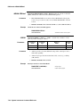
Mainframe Specifications . . . . . . . . . . . .
Pacer (50% duty cycle): . . . . . . . . . . . .
Real-time Clock: . . . . . . . . . . . . . . . .
Trigger Input: . . . . . . . . . . . . . . . . .
Non-volatile added memory storage lifetime:
Slots: . . . . . . . . . . . . . . . . . . . . . .
EMC, RFI, Safety: . . . . . . . . . . . . . . .
Size: . . . . . . . . . . . . . . . . . . . . . . .
Weight: . . . . . . . . . . . . . . . . . . . . .
Power: . . . . . . . . . . . . . . . . . . . . . .
Cooling: . . . . . . . . . . . . . . . . . . . . .
Humidity: . . . . . . . . . . . . . . . . . . . .
Operating temperature: . . . . . . . . . . . .
Storage temperature: . . . . . . . . . . . . .
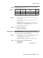
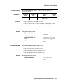
SCPI Conformance Information . . . . . . . . .
Switchbox Configuration . . . . . . . . . . .
Multimeter Commands . . . . . . . . . . . .
Counter Commands . . . . . . . . . . . . . .
D/A Converter Commands . . . . . . . . . .
Digital I/O Commands . . . . . . . . . . . .
System Instrument Commands . . . . . . . .
.
.
.
.
.
.
.
.
.
.
.
.
.
.
.
.
.
.
.
.
.
.
.
.
.
.
.
.
.
.
.
.
.
.
.
.
.
.
.
.
.
.
.
.
.
.
.
.
.
.
.
.
.
.
.
.
.
.
.
.
.
.
.
.
.
.
.
.
.
.
.
.
.
.
.
.
.
.
.
.
.
.
.
.
.
.
.
.
.
.
.
.
.
.
.
.
.
.
.
.
.
.
.
.
.
.
.
.
.
.
.
.
.
.
.
.
.
.
.
.
.
.
.
.
.
.
.
.
.
.
.
.
.
.
.
.
.
.
.
.
.
.
.
.
.
.
.
.
.
.
.
.
.
.
.
.
.
.
.
.
.
.
.
.
.
.
.
.
.
.
.
.
.
.
.
.
.
.
.
.
.
.
.
.
.
.
.
.
.
.
.
.
.
.
.
.
.
.
.
.
.
.
.
.
.
.
.
.
.
.
.
.
.
.
.
.
.
.
.
.
.
.
.
.
.
.
.
.
.
.
.
.
.
.
.
.
.
.
.
.
.
.
.
.
.
.
.
.
.
.
.
.
.
.
.
.
.
.
.
.
.
.
.
.
.
.
.
.
.
.
.
.
.
.
.
.
.
.
.
.
.
.
.
.
.
.
.
.
.
.
.
.
.
.
.
.
.
.
.
.
.
.
.
.
.
.
.
.
.
.
.
.
.
.
.
.
.
.
.
.
.
.
.
.
.
.
.
.
.
.
.
.
.
.
.
.
.
.
.
.
.
.
.
.
.
.
.
.
.
.
.
.
.
.
.
.
.
.
.
.
.
.
.
.
.
.
.
.
.
.
.
.
.
.
.
.
.
.
.
.
.
.
.
.
.
.
.
.
.
.
.
.
.
.
.
.
.
.
.
.
.
.
.
.
.
.
.
.
.
.
.
.
.
.
.
.
.
.
.
.
.
.
.
.
.
.
.
.
.
.
.
.
.
.
.
.
.
.
.
.
.
A-1
A-1
A-1
A-1
A-1
A-1
A-1
A-2
A-2
A-2
A-2
A-2
A-2
A-2
A-3
A-3
A-4
A-6
A-8
A-9
A-10
.
.
.
.
.
.
.
.
.
.
.
.
.
.
.
.
.
.
.
.
.
.
.
.
.
.
.
.
.
.
.
.
.
.
.
.
.
.
.
.
.
.
.
.
.
.
.
.
.
.
.
.
.
.
.
.
.
.
.
.
.
.
.
.
.
.
.
.
.
.
.
.
.
.
.
.
.
.
.
.
.
.
.
.
.
.
.
.
.
.
.
.
.
.
.
.
.
.
.
.
.
.
.
.
.
.
.
.
.
.
.
.
.
.
.
.
.
.
.
.
.
.
.
.
.
.
.
.
.
.
.
.
.
.
.
.
.
.
.
.
.
.
.
.
.
.
.
.
.
.
.
.
.
.
.
.
.
.
.
.
.
.
.
.
.
.
.
.
B-1
B-1
B-2
B-2
B-2
B-2
B-2
B-5
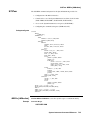
B. Error Messages
Using This Appendix . . . . . . . . . .
Reading an Instrument’s Error Queue
Error Types . . . . . . . . . . . . . . .
Command Errors . . . . . . . . . .
Execution Errors . . . . . . . . . . .
Device-Specific Errors . . . . . . .
Query Errors . . . . . . . . . . . . .
Start-up Error Messages . . . . . . . .
4 - Table of Contents
.
.
.
.
.
.
.
.
.
.
.
.
.
.
.
.
.
.
.
.
.
.
.
.
.
.
.
.
.
.
.
.
.
.
.
.
.
.
.
.
C. Connecting and Configuring a Display Terminal
Using this Appendix . . . . . . . . . . . . .
Overview . . . . . . . . . . . . . . . . . . . .
Connecting a Terminal to the Mainframe . .
Configuring a Terminal for the Mainframe .
Starting with Default Mainframe Settings
Restoring the Default Configuration . . .
Configuring the Terminal . . . . . . . . .
Trying it . . . . . . . . . . . . . . . . . . .
Configuring the Mainframe with Menus . .
.
.
.
.
.
.
.
.
.
.
.
.
.
.
.
.
.
.
.
.
.
.
.
.
.
.
.
.
.
.
.
.
.
.
.
.
.
.
.
.
.
.
.
.
.
.
.
.
.
.
.
.
.
.
.
.
.
.
.
.
.
.
.
.
.
.
.
.
.
.
.
.
.
.
.
.
.
.
.
.
.
.
.
.
.
.
.
.
.
.
.
.
.
.
.
.
.
.
.
.
.
.
.
.
.
.
.
.
.
.
.
.
.
.
.
.
.
.
.
.
.
.
.
.
.
.
.
.
.
.
.
.
.
.
.
.
.
.
.
.
.
.
.
.
.
.
.
.
.
.
.
.
.
.
.
.
.
.
.
.
.
.
.
.
.
.
.
.
.
.
.
.
.
.
.
.
.
.
.
.
.
.
.
.
.
.
.
.
.
.
.
.
.
.
.
.
.
.
.
.
.
.
.
.
.
.
.
C-1
C-1
C-1
C-3
C-3
C-3
C-3
C-4
C-4
About this Appendix . . . . . . . . . . . . . . . .
Formatting Binary Data for RS-232 Transmission
Sending Binary Data Over RS-232 . . . . . . . .
Setting Up the Mainframe . . . . . . . . . . .
.
.
.
.
.
.
.
.
.
.
.
.
.
.
.
.
.
.
.
.
.
.
.
.
.
.
.
.
.
.
.
.
.
.
.
.
.
.
.
.
.
.
.
.
.
.
.
.
.
.
.
.
.
.
.
.
.
.
.
.
.
.
.
.
.
.
.
.
.
.
.
.
.
.
.
.
.
.
.
.
D-1
D-1
D-2
D-2
D. Sending Binary Data Over RS-232
Table of Contents - 5
6 - Table of Contents
Chapter
1
Getting Started
Using This Chapter
This chapter describes the Agilent E1300B/E1301B Mainframe, defines the
instrument concept, and explains how plug-in modules are designated as
instruments in the mainframe. This chapter also contains introductory
programming examples showing how to read and set the mainframe’s clock and
calendar. This chapter contains the following sections:
• Mainframe Description . . . . . . . . . . . . . . . . . . . . . . . . . . . . . . . . . 1-1
• Instrument Definition . . . . . . . . . . . . . . . . . . . . . . . . . . . . . . . . . . 1-3
• Introductory Programming Examples . . . . . . . . . . . . . . . . . . . . 1-4
1
Mainframe
Description
The Agilent E1301B mainframe contains a front panel keyboard and display; the
Agilent E1300B has no keyboard or display. Otherwise, there is no conceptual
difference between the two mainframes. Both models provide a terminal based
user interface (Display Terminal Interface) through the built-in, or optional
plug-in serial interfaces. The front panel keyboard and display are discussed in
Chapter 2 of this manual. The Display Terminal Interface is discussed in
Chapter 3.
The mainframe handles such high level operations as language translation of
IEEE-488.2 Common Commands and SCPI (Standard Commands for
Programmable Instruments) commands; module-to-module synchronization;
and memory management. When installed in the mainframe, SCPI-compatible
register-based plug-in modules behave as independent instruments operating
under control of SCPI commands and Common Commands. Plug-in modules
that are not SCPI-compatible must be programmed at a register level (see the
VXI:REG:WRITE and VXI:REG:READ? commands in Chapter 5 of this
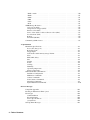
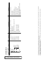
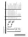
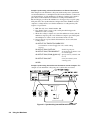
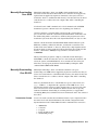
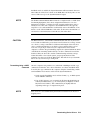
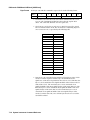
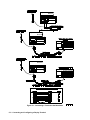
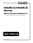
manual for more information). Figure 1-2 shows the E1300B/E1301B
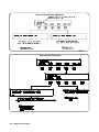
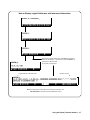
Mainframe’s A- and B-size plug-in module slots, GPIB* connector, RS-232 port,
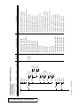
and input/output ports.
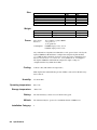
Optional Mainframe
Memory
*
The mainframe comes from the factory with 256 kBytes of non-volatile memory
(RAM) for reading storage. You can install up to 2 MBytes of optional RAM.
The E1320A provides 500 kBytes while the E1321A provides 1 MByte of
memory. Optional RAM replaces the standard memory and is not in addition to
it (e.g. the mainframe with an optional 1 Mbyte module has 1Mbyte available).
GPIB is the implementation of IEEE Std 488.1-1978.
Getting Started
1-1
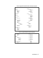
GPIB
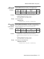
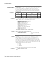
Trig Out: Allows an instrument to output a negative-going pulse to indicate the
occurrence of some event such as closing a channel on a Switchbox Instrument.
The signal levels are standard TTL (0V to 5V). This pulse can be used to
synchronize external equipment to the instrument (see Chapter 5 for examples).
You direct the pulse from the appropriate instrument to the Trig Out port using
the OUTP:STAT ON command.
Pacer Out: Allows you to output a square wave signal to trigger or pace external
equipment such as scanners or voltmeters. You can control the period of the
square wave signal and the number of periods output. The signal levels are
standard TTL (0V to 5V). Refer to Chapters 4 and 5 for more information on
the Pacer.
Event In: Allows an instrument to be armed or triggered from an external
negative-going signal. The signal levels are standard TTL (0V to 5V). Use an
instrument’s ARM:SOUR:EXT command or the TRIG:SOUR:EXT command
to direct the Event In port to that instrument.
RS-232: Serial interface provides a user interface using a terminal or a
computer running terminal emulator software. The user interface provides the
functionality of the E1301’s keyboard and display. If present, the optional
IBASIC interpreter can be configured to control the RS-232 port.
Figure 1-1. Mainframe Features
1-2
Getting Started
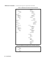
1
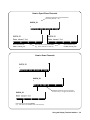
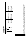
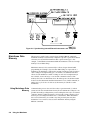
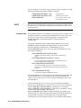
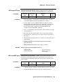
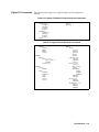
Instrument
Definition
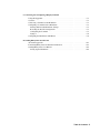
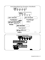
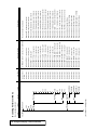
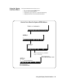
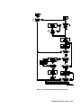
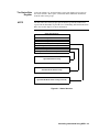
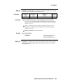
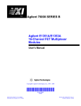
SCPI-compatible plug-in modules installed in the mainframe are treated as
independent instruments each having a unique secondary GPIB address. As
shown in Figure 1-3, each instrument is assigned a dedicated error queue, input
and output buffers, status registers and, if applicable, dedicated mainframe
memory space for readings or data. An instrument may be composed of a single
plug-in module (such as a counter) or multiple plug-in modules (for a Switchbox
or Scanning Voltmeter Instrument). In addition, the mainframe contains a
built-in instrument called the System Instrument which has a Pacer for timing
external devices. The System Instrument also can control the built-in RS-232, as
well as up to seven optional Agilent E1324A plug-in serial interfaces.
Figure 1-2. Instrument Concept
Getting Started
1-3
Instrument Logical
Addresses
Instruments are identified by a logical address which directly relates to its GPIB
secondary address. Instruments come from the factory with a preset logical
address. You can change the factory setting during installation (see the "Agilent
75000 Series B Installation and Getting Started Guide" for instructions).
A single-module instrument must have its logical address set to an integer
multiple of 8 (0, 8, 16, 24, ... 240). In a multiple-module instrument, only one of
the modules has a logical address that is an integer multiple of 8. The other
modules in the multiple-module instrument must have consecutive logical
addresses. For example, in a Scanning Voltmeter, if the voltmeter module has a
logical address of 16, the other modules in that instrument must have logical
addresses of 17, 18, 19 and so on. The same applies to the System Instrument
who’s logical address fixed at 0. An E1324A plug-in serial interface controlled
by the System Instrument would be set to logical address 1. A second E1324A
would be set to logical address 2 and so on.
Instrument Secondary
Addresses
An instrument’s GPIB secondary address is simply the logical address divided
by 8 (for a multiple-module instrument, the lowest logical address divided by 8).
For example, an instrument with a logical address of 16 has a secondary address
of 02. The secondary address allows access to a particular instrument when
programming via GPIB. (The System Instrument’s secondary address is 00 and
is the only address that cannot be changed).
Unassigned Modules
An unassigned module in an E1300B/E1301B Mainframe is one that does not
have a logical address that is a multiple of 8 (8, 16, 24...240) and is not part of a
Scanning Voltmeter or Switchbox configuration. You can only program these
modules at the register level using the VXI:WRITE and VXI:READ?
commands (see Chapter 5 of this manual for more information on these
commands).
1
Introductory
Programming
Examples
This section shows how to send SCPI and Common Commands to the
mainframe’s System Instrument and how to read data back. The following
assumes that you send the commands or read the data over GPIB. To send SCPI
commands or to read data, specify the:
•
•
•
•
Computer’s GPIB interface address
Mainframe’s GPIB primary address
Instrument’s GPIB secondary address
SCPI command string or Common Command
For instruments in the mainframe, the primary address is the same as the
mainframe address (i.e., the factory setting is 09). The instrument’s secondary
address is simply the logical address divided by 8 (e.g., logical addresses of 8, 16,
24, or 32, result in secondary addresses of 01, 02, 03, or 04, respectively).
1-4
Getting Started
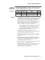
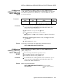
Example: Reading the Time
This program reads and prints the time from the System Instrument’s internal
clock. The computer used in the example is an Agilent Series 200/300 computer
with Agilent BASIC as the program language. The computer interfaces to the
mainframe using the General Purpose Interface Bus (GPIB). The GPIB
interface select code is 7, the GPIB primary address is 09, and the GPIB
secondary address is 00 (System Instrument). Resulting in a combined address
of 70900.
10 OUTPUT 70900;"* RST"
20 OUTPUT 70900;"SYST:TIME?"
30 ENTER 70900; H,M,S
40 PRINT H,M,S
50 END
Typical response: + 16, + 15, + 30
Example: Setting the Time
Reset System Instrument using
Common Command
Send SCPI query command to
return time
Place hour in H, minutes in M,
seconds in S
Print time
(4:15:30 PM)
Set the clock using the 24 hour hour,minute,second format. Execute the
following line to set the time to 14,00,00 (i.e., 2:00:00 PM).
SYST:TIME 14,00,00
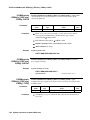
Example: Reading the Date
This program reads and prints the date stored in the mainframe’s internal
calendar.
10 OUTPUT 70900;"SYST:DATE?"
20 ENTER 70900; Y,M,D
30 PRINT Y,M,D
40 END
Typical response: + 1989, + 9, + 16
Example: Setting the Date
Send SCPI query command to
return date
Place year in Y, month in M,
day in D
Print date
(September 16, 1989)
Set the date using the YYYY,MM,DD format. Executing the following line sets
the date to 1990,1,13 (January 13, 1990).
SYST:DATE 1990,1,13
Getting Started
1-5
1-6
Getting Started
Chapter
2
Using the Front Panel
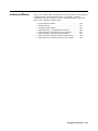
Using this Chapter
This chapter shows you how to use the Agilent E1301B Mainframe’s front panel
keyboard and display to operate instruments in the mainframe. It contains the
following sections:
•
•
•
•
•
•
Front Panel Features . . . . . . . . . . . . . . . . . . . . . . . . . . . . . . . . . . . 2-1
Using Menus . . . . . . . . . . . . . . . . . . . . . . . . . . . . . . . . . . . . . . . . . . 2-2
Executing Commands . . . . . . . . . . . . . . . . . . . . . . . . . . . . . . . . . . 2-9
Key Descriptions . . . . . . . . . . . . . . . . . . . . . . . . . . . . . . . . . . . . . 2-10
In Case of Difficulty. . . . . . . . . . . . . . . . . . . . . . . . . . . . . . . . . . . 2-12
Instrument Menus . . . . . . . . . . . . . . . . . . . . . . . . . . . . . . . . . . . . 2-13
1
Front Panel
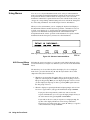
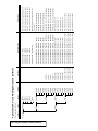
Features
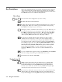
2-Line X 40 Character Display
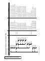
Figure 2-1 shows the front panel’s QWERTY keyboard and the dedicated key
groupings. The tutorials in this chapter show how to use most of the dedicated
keys. See “Key Descriptions” near the end of this chapter for a complete
description of each dedicated key.
Display Control and
Editing Keys
Menu Keys
Agilent
Instrument
Control Keys
QWERTY Keyboard
Figure 2-1. Front Panel Features
Using the Front Panel 2-1
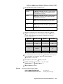
1
Using Menus
You can access a System Instrument menu and a variety of other instrument
menus (depending on installed instruments) from the front panel. These menus
incorporate the most used functions but do not provide access to all of the
instrument commands. If a particular function is not available from a menu, you
can type the corresponding command string and execute it from the front panel.
See “Executing Commands” later in this chapter for more information.
When you select an instrument, you are assigning the keyboard and display to
that instrument. This means that any menu operations, commands executed or
recalled, errors displayed, etc. pertain only to that instrument. Front panel
operation of an instrument is independent from other instruments and
independent from the remote operation of the instrument. To operate another
instrument from the front panel, you must select that instrument.
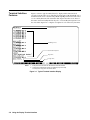
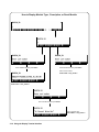
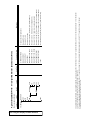
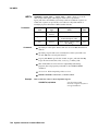
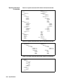
Note: Typical instruments shown. Actual choices depend on installed instruments
Figure 2-2. Select an Instrument Menu
A 60-Second Menu
Tutorial
Following the power-on sequence or a system reset the display shows the Select
an instrument menu (see Figure 2-2) which lets you select one of the instruments
listed.
The menu keys are located directly below the display. To select a displayed
menu choice, press the function key (f1 - f5) directly below the choice. This
chapter shows key labels in bold text.
• When there are more than five menu choices, an arrow appears on the
right side of the display. Press More to display the next group of choices.
By repeatedly pressing More you can display all groups of choices. After
you have displayed all groups of choices, pressing More again returns to
the first group of choices.
• When the display is requesting information (input prompt) such as Enter
the device’s logical address, just type the information and press Return.
If you press the wrong menu key and do not want to enter the
requested information, you can escape the input prompt and stay at
the same menu level by pressing ESC or Prev Menu.
If you make an incorrect entry in response to an input prompt, the
top line of the display will show an error message. When this
happens, just select that menu choice again (f1 - f5 keys), re-type the
correct information, and press Return.
2-2 Using the Front Panel
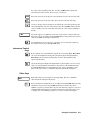
• Press Prev Menu to return to the previous menu within an instrument
menu or escape from an input prompt. Press Select Instr to return to the
Select an Instrument menu. Note that when you leave an instrument and
return later, you return to the same menu location you were when you
left. In addition, any other displayed information (instrument responses
or commands being entered) will also be displayed when you return.
• In addition to the menu keys, Clear Instr and Reset Instr are helpful
when operating an instrument. Clear Instr clears the instrument’s front
panel input and output buffers (remote buffers are not cleared) and
returns to the top level of the instrument menu. Press Clear Instr
whenever an instrument is busy, is not responding to front panel control,
or to abort a command being entered from the front panel. Reset Instr
clears all front panel and remote input and output buffers and resets the
instrument.
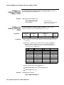
Using the System
Instrument Menu
The System Instrument menu allows you to:
•
•
•
•
Set or read the system GPIB address
Reset (reboot) the mainframe
Display the logical addresses of installed instruments
Display information about installed instruments
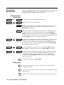
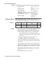
How to Set or Read the System GPIB Address
GPIB
GPIB
GPIB
Using the Front Panel 2-3
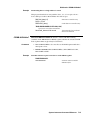
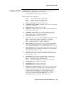
How to Reset the System
GPIB
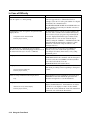
Note: The RESET menu selection is equivalent to the DIAG:BOOT command which has the same effect as cycling power to the mainframe.
Pressing Reset Instr from the System Instrument menu is equivalent to executing the *RST command which resets the System Instrument.
How to Display Logical Addresses or Instrument Information
GPIB
2-4 Using the Front Panel
Using the Other
Instrument Menus
The instrument menus allow you to access the most-used instrument functions
or to monitor an instrument (monitor mode) while it is being controlled from
remote. We’ll use the Switchbox menu to show you how to use the instrument
menus. Menus are available for many but not all instruments. See “Instrument
Menus”, later in this chapter, for more information on a particular instrument’s
menu. The Switchbox menu allows you to:
•
•
•
•
•
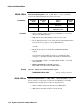
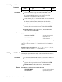
Selecting the Switchbox
Note
Open and Close Channels
Scan Channels
Display Module Type and Description
Monitor a Switchbox
Reset a selected switch module
To select the Switchbox, press the function key (f1 - f5) directly below the word
SWITCH in the “Select an instrument” menu. (If the “Select an instrument”
menu is not being displayed press Select Instr.)
After you press the function key below the word SWITCH, the top line of the
display may show: “Select SWITCH at logical address:_” while the bottom line of
the display lists two or more logical addresses. This means more than one
Switchbox is installed in the mainframe. To select one of the Switchboxes, press
the function key directly below the corresponding logical address.
The charts on the following pages show how to use the Switchbox menu. Keep
the following points in mind when using the menu:
• The card number identifies a module within the Switchbox. The module
with the lowest logical address is always card number 01. The module
with the next successive logical address is card number 02 and so on.
• The @ character is required preceding a channel list when executing a
Switchbox command from the front panel or remote. When entering a
channel list in response to a menu prompt however, do not precede it
with the @ character. Doing so causes a syntax error.
Using the Front Panel 2-5
How to Open/Close Channels
How to Scan Channels
2-6 Using the Front Panel
How to Display Monitor Type, Description, or Reset Module
How to Select Monitor Mode
Using the Front Panel 2-7
Monitor Mode
Monitor mode displays the status of an instrument while it is being controlled
from remote. Monitor mode is useful for debugging programs. You can place an
instrument in monitor mode using front panel menus, or by executing the
DISP:MON:STAT ON command from the front panel or by remote. (Executing
the remote DISP:MON:STAT ON command is the only way to assign the
display/keyboard to an instrument from remote.) Pressing most front panel keys
will automatically exit monitor mode and return to the instrument menu.
However, you can use the left and right arrow keys in monitor mode to view long
displays.
Note
Enabling monitor mode slows instrument operations. If the timing or speed of
instrument operations is critical (such as making multimeter readings at a
precise time interval), you should not use monitor mode.
Table 2-8 shows the status annunciators that may appear in the bottom line of
the display in monitor mode. Some instruments also have device-specific
annunciators (see the plug-in module manual for more information).
Table 2-1. Monitor Mode Display Annunciators
Annunciator
Reading Error Messages
Description
mon
The instrument is in monitor mode
bsy
The instrument is executing a command
err
An error has occurred (see “Reading Error
Messages” below)
srq
A service request has occurred
Whenever the display is showing the err annunciator, an error has occurred for
the instrument being monitored. You can read the error message, although
doing so cancels monitor mode. To read an error message, press the following
keys:
The error message will be displayed in the top line of the display. To see if
another error was logged, repeat the above keystrokes or press:
After you have read all the error messages, executing the SYST:ERR?
command causes the display to show: + 0 No error. After reading the error
message(s), press f1 to return to monitor mode.
2-8 Using the Front Panel
1
Executing
Commands
From the front panel, you can type and execute IEEE 488.2 Common
Commands and SCPI Commands for the instrument presently selected by the
Select an instrument menu. (However, you cannot execute a command when the
display is requesting that you input information.) This is particularly useful for
accessing functions not available in an instrument’s menu. For example, the
System Instrument contains a Pacer that can be programmed to output a square
wave signal on the mainframe’s Pacer Out port. From the System Instrument
menu, you can program the Pacer to output 10 square wave cycles with a period
of 1 second each by typing the following commands and pressing Return after
each command (see Chapter 3 for more information on the Pacer).
SOUR:PULS:COUN 10
SOUR:PULS:PER 1
INIT:IMM
TRIG:SOUR IMM
As another example, after selecting the Switchbox, suppose you must set up and
execute a scan list with automatic advance (automatic advance is not available
from the menu). You can do this by typing the following command string and
pressing Return (notice that by linking the commands together with a semicolon
and colon you need press Return only once).
TRIG:SOUR IMM;:SCAN (@100:105);:INIT
Editing
The display editing keys (shown on the following page) allow you to edit
user-entered data or commands. When editing, the display is in insert mode.
That is, typed characters will be inserted into the string at the present cursor
position.
Using the Front Panel 2-9
1
Key Descriptions
This section explains the function of each of the front panel’s dedicated keys. If
a key is not functional in a particular situation, pressing that key does nothing
except to cause a beep. Users of the optional IBASIC interpreter should refer to
their IBASIC manual set for additional editing functions.
Menu Keys
Selects the menu choice displayed directly above each key.
Returns to the Select an instrument menu.
Returns to the previous menu level within an instrument menu or escapes from
an input prompt. When you reach the top of an instrument’s menu, pressing
Prev Menu does nothing except to cause a beep.
The display can show a maximum of five menu choices at a time. When there are
more than five menu choices, an arrow appears on the right side of the display.
Press More to display the next group of choices. By repeatedly pressing More
you can display all groups of choices. After you have displayed all groups of
choices, pressing More again returns to the first group of choices.
Recalls the last command entered from the front panel. After recalling a
command, it can be edited or re-executed. You can recall from a stack of
previously executed commands by repeatedly pressing Recall Prev. When you
reach the bottom of the stack (the last line in the buffer), pressing Recall Prev
does nothing except to cause a beep. Pressing Shift with Recall Prev recalls the
last SCPI command generated by a menu operation. For example, reading the
time using the menus (SYSTEM, TIME, READ) generates and executes the
SCPI command SYST:TIME?. A recalled command can be executed by
pressing the Return key. You can also edit a recalled command before you
execute it.
Accesses commands in the opposite order to that of Recall Prev. Pressing Recall
Next does nothing until you have pressed Recall Prev at least twice.
Performs the same function as Prev Menu.
Display Control &
Editing Keys
(Right arrow key.) Moves the cursor one character space to the right while
leaving characters intact. Use the right arrow key to scroll displays that are
longer than the display size. Pressing Shift followed by the right arrow key
moves the cursor to the end of the line. Pressing CTRL followed by the right
arrow key moves the cursor 4 character spaces to the right.
(Left arrow key.) Moves the cursor one character space to the left while leaving
characters intact. Use the left and right arrow keys to scroll displays that are
longer than the display size. Pressing Shift followed by the left arrow key moves
2-10 Using the Front Panel
the cursor to the beginning of the line. Pressing CTRL followed by the left
arrow key moves the cursor 4 character spaces to the left.
Erases the character at the present cursor position (for user-entered data only).
Erases the character to the left of the cursor (for user-entered data only).
(Clear-to-end key.) Erases all characters from the present cursor position to the
end of the input line (for user-entered data only). Pressing Shift followed by the
clear-to-end key erases the entire line and moves the cursor to the beginning of
the line.
Selects the upper-case alphabetic characters or the character shown on the top
half of a key. You can either hold down Shift while pressing another key or press
and release Shift and then press another key.
Sets all alphabetic keys to uppercase (capitals); does not affect the other keys.
To return to lowercase, press Caps Lock again.
Instrument Control
Keys
Resets only the selected instrument (equivalent of executing *RST). Reset Instr
also clears the instrument’s front panel and remote input and output buffers.
Reset Instr is the only front panel key that can affect an instrument being
operated from remote.
Clears the front panel input and output buffers (remote buffers are not cleared)
of the selected instrument and returns to the top level of the instrument menu.
Press Clear Instr whenever an instrument is busy, is not responding to front
panel control, or to abort a command being entered from the front panel.
Other Keys
End of line. Enters your responses to menu prompts. Executes commands
entered from the front panel keyboard.
Selects alternate key definitions. You can either hold down CTRL while pressing
another key or press and release CTRL and then press another key. These
CTRL key sequences provide short-cuts for some menu key sequences as well as
additional functions not directly available from dedicated front panel keys. For
a complete list of all CTRL key sequences see table 3-3 in the next chapter.
Using the Front Panel 2-11
1
In Case of Difficulty
Problem:
Problem Cause/Solution:
Error -113 undefined header error occurs after entering
data in response to a menu prompt.
For some commands used by the menus, the data
entered is appended to a command header. For
example, if you enter "1" as the port number for a digital
I/O module, the command used is
DIG:HAND1:MODE NONE where HAND1 indicates
the port number. If your entry was invalid or incorrect,
error -113 occurs.
Following the power-on sequence or system reset the
display shows:
An unnassigned device (incorrect logical address) was
detected, or the contents of non-volatile memory may
have been lost, If you cycle power or perform system
reset, the display will show the logical address of the
unassigned device. You can also check the logical
addresses using the CONFIG? -- LADDS branch of the
System Instrument menu. Refer to Chapter 1 of this
manual for a discussion of logical addresses and
unassigned devices.
Configuration errors. Select SYSTEM
Press any key to continue_
The display shows: "instrument in local lockout".
Menus seem to work but nothing happens when I reach
the bottom level or try to execute a command.
The front panel has been locked-out (GPIB local
lockout). You can re-enable menu operation by
cancelling local lockout (from remote) or by cycling
mainframe power.
Display cannot be removed from monitor mode.
Monitor mode was entered from remote
(DISP:MON:STAT ON command) and the front panel
has also been locked out (GPIB local lockout). Either
cancel the local lockout or execute
DISP:MON:STAT OFF (from remote).
Display shows:
A hardware or software problem has occured in the
instrument preventing it from responding to front panel
control.
Can not connect to instrument
Press any key to continue_
After selecting an instrument the display shows:
busy.
Display shows:
Instrument in use by another display.
Press any key to continue_
2-12 Using the Front Panel
The instrument is busy performing an operation. Press
Clear Instr to abort the instrument operations and
allow the front panel to access the instrument.
The instrument has already been selected from the
Display Terminal Interface. An instrument can only be
“attached” to one display at a time. At the terminal,
return to the “Select instrument” menu. The instrument
can now be selected from the Front Panel.
2
Instrument Menus
This section contains charts showing the structure and content for all front panel
instrument menus. Also shown in the charts are the SCPI or Common
Commands used and descriptions of menu-controlled instrument operations.
This section contains the following charts:
•
•
•
•
•
•
•
•
System Instrument Menu. . . . . . . . . . . . . . . . . . . . . . . . . . . . . . .
Switchbox Menu . . . . . . . . . . . . . . . . . . . . . . . . . . . . . . . . . . . . . .
Scanning Voltmeter Menu . . . . . . . . . . . . . . . . . . . . . . . . . . . . .
Agilent E1326A 5 1/2 Digit Multimeter Menu . . . . . . . . . . . . .
Agilent E1328A 4-Channel D/A Converter Menu. . . . . . . . . .
Agilent E1330A Quad 8-Bit Digital I/O Menu. . . . . . . . . . . . .
Agilent E1332A 4-Channel Counter/Totalizer Menu . . . . . . .
Agilent E1333A 3-Channel Universal Counter Menu. . . . . . .
2-14
2-16
2-18
2-20
2-21
2-22
2-24
2-26
Using the Front Panel 2-13
2-14 Using the Display Terminal Interface
CONFIG?
SYSTEM
Command(s) Used
PACE
BITS
PARITY
card number
card number
9600
19200
card number
card number
card number
XON/ OFF
NONE
READ
card number
8
SET
card number
NONE
7
card number
ZERO
SET
card number
ONE
card number
card number
ODD
READ
card number
card number
EVEN
SET
card number
2400
card number
card number
1200
READ
card number
300
SET
SYST:COMM:SER[ n] :PACE NONE
SYST:COMM:SER[ n] :PACE XON
SYST:COMM:SER[ n] :PACE?
SYST:COMM:SER[ n] :BITS 8
SYST:COMM:SER[ n] :BITS 7
SYST:COMM:SER[ n] :BITS?
SYST:COMM:SER[ n] :PAR NONE
SYST:COMM:SER[ n] :PAR ZERO
SYST:COMM:SER[ n] :PAR ONE
SYST:COMM:SER[ n] :PAR ODD
SYST:COMM:SER[ n] :PAR EVEN
SYST:COMM:SER[ n] :PAR?
SYST:COMM:SER[ n] :BAUD 19200
SYST:COMM:SER[ n] :BAUD 9600
SYST:COMM:SER[ n] :BAUD 2400
SYST:COMM:SER[ n] :BAUD 1200
SYST:COMM:SER[ n] :BAUD 300
SYST:COMM:SER[ n] :BAUD?
SYST:COMM:GPIB:ADDR < address>
card number
GPIB address
READ
SET
BAUD
SYST:COMM:GPIB:ADDR?
READ
logical address
User Entry
VXI:CONF:DLIS? < log_addr>
Level 6
DEVICE
Level 5
VXI:CONF:DLAD?
Level 4
LADDS
Level 3
(continued on following page)
RS232
GPIB
Level 2
Level 1
Menu Levels and Content
System Instrument Menu
Disables XON/ XOFF software handshaking
Enables XON/ XOFF software handshaking
Read current pacing type
Sets the data width to 8 bits
Sets the data width to 7 bits
Read current data bit width
Sets the serial interface parity to none
Sets the serial interface parity to zero
Sets the serial interface parity to one
Sets the serial interface parity to odd
Sets the serial interface parity to even
Read current parity type
Sets the serial interface baud rate to 19200
Sets the serial interface baud rate to 9600
Sets the serial interface baud rate to 2400
Sets the serial interface baud rate to 1200
Sets the serial interface baud rate to 300
Read current baud rate
Displays GPIB address
Displays information about the device at
the specified logical address. (Refer to the
Command Reference for details)
Displays logical addresses of mainframe
instruments
Description
Using the Display Terminal Interface 2-15
Level 2
Level 3
RESET
DATE
TIME
DEBUG
card number
card number
card number
OFF
IBFULL
STANDRD
DIAG:BOOT
SYST:DATE < date>
date
SET
SYST:TIME < time>
SYST:DATE?
time
SET
READ
SYST:TIME?
VXI:WRIT < laddr> ,< reg> ,< data>
VXI:READ? < laddr> ,< reg>
DIAG:COMM:SER[ n] :STORE
SYST:COMM:SER[ n] :CONT:RTS STAN
SYST:COMM:SER[ n] :CONT:RTS IBF
SYST:COMM:SER[ n] :CONT:RTS OFF
SYST:COMM:SER[ n] :CONT:RTS ON
SYST:COMM:SER[ n] :CONT:RTS?
SYST:COMM:SER[ n] :CONT:DTR STAN
SYST:COMM:SER[ n] :CONT:DTR IBF
SYST:COMM:SER[ n] :CONT:DTR OFF
SYST:COMM:SER[ n] :CONT:DTR ON
SYST:COMM:SER[ n] :CONT:DTR?
Command(s) Used
READ
laddr,
reg_num, data
WRITE
card number
card number
ON
card number
STANDRD
SET
card number
IBFULL
card number
card number
OFF
READ
card number
ON
SET
User Entry
card number
Level 6
READ
Level 5
laddr, reg_num
RTS
DTR
Level 4
READ
STORE
CONTROL
(continued from previous page)
Level 1
Menu Levels and Content
System Instrument Menu
Resets mainframe using the configuration
stored in non-volatile memory
Set the system calendar
Read the current system calendar
Set the system clock
Read the current system clock
Write data to register in A16 address space.
Read register in A16 address space.
Store current serial communications
settings into non-volatile storage.
RTS operates to RS-232 standard
Set RTS for hardware handshaking
Set RTS line to static -V
Set RTS line to static + V
Read current setting for RTS line
DTR operates to RS-232 standard
Set DTR for hardware handshaking
Set DTR line to static -V
Set DTR line to static + V
Read current setting for DTR line
Description
2-16 Using the Display Terminal Interface
User Entry
TEST
card number ‡
card number ‡
card number ‡
DESCR?
RESET
channel list †
STEP
SCAN
TYPE?
channel list †
SET_UP
CLOSE
CARD
channel list †
channel list †
OPEN
card number ‡ or AUTO
Level 3
MONITOR
Level 2
* TST?
SYST:CPON < card_number>
SYST:CDES? < card_number>
SYST:CTYP? < card_number>
TRIG
TRIG:SOUR HOLD;:SCAN < channel_list> ;:INIT
CLOS (@channel_list)
OPEN (@channel_list)
DISP:MON:CARD < card_number> ;STAT ON
Command(s) Used
Runs self-test, displays results (+ 0= pass; any
other number= fail)
Return module to power-on state
Display module description
Display module ID information
Step to next channel in scan list
Set up channels to scan
Close channel(s)
Open channel(s)
Monitor instrument operations
Description
‡ The card number identifies a module within the Switchbox. The switch module with the lowest logical address is always card number 01. The switch module with the next
successive logical address is card number 02 and so on.
† Channel lists are of the form “ccnn” (single channel), “ccnn,ccnn” (two or more channels) or “ccnn:ccnn” (range of channels); where “cc” is the card number and “nn” is the channel
number. For example, to access channel 2 on card number 1 specify 102.
SWITCH
Level 1
Menu Levels and Content
Switchbox Menu
Notes
Using the Front Panel 2-17
2-18 Using the Display Terminal Interface
channel list †
VDC
channel list †
channel list †
S
T
channel list †
channel list †
channel list †
BENDING
BENPOIS
POISSON
channel list †
POISSON
FULL
channel list †
channel list †
BENDING
channel list †
392
HALF
channel list †
385
QUARTER
RTD
(continued on following page)
STRAIN
channel list †
R
channel list †
channel list †
N28
channel list †
channel list †
N14
10K
channel list †
K
5K
channel list †
J
channel list †
channel list †
E
TEMP
2252
channel list †
B
OHM
THERMIS
channel list †
channel list †
VAC
TCOUPLE
channel list † or 0
for auto
User Entry
MONITOR
Level 4
VOLTMTR
Level 3
Level 2
Level 1
Menu Levels and Content
Scanning Voltmeter Menu
MEAS:STR:FPO? < channel_list>
MEAS:STR:FBP? < channel_list> ,
MEAS:STR:FBEN? < channel_list>
MEAS:STR:HPO? < channel_list>
MEAS:STR:HBEN? < channel_list>
MEAS:STR:QUAR? < channel_list>
MEAS:TEMP? RTD,92,< channel_list>
MEAS:TEMP? RTD,85,< channel_list>
MEAS:TEMP? THER,10000,< channel_list>
MEAS:TEMP? THER,5000,< channel_list>
MEAS:TEMP? THER,2252,< channel_list>
MEAS:TEMP? TC,T, < channel_list>
MEAS:TEMP? TC,S, < channel_list>
MEAS:TEMP? TC,R, < channel_list>
MEAS:TEMP? TC,N28, < channel_list>
MEAS:TEMP? TC,N14, < channel_list>
MEAS:TEMP? TC,K, < channel_list>
MEAS:TEMP? TC,J, < channel_list>
MEAS:TEMP? TC,E, < channel_list>
MEAS:TEMP? TC,B, < channel_list>
MEAS:RES? < channel_list>
MEAS:VOLT:AC? < channel_list>
MEAS:VOLT:DC? < channel_list>
DISP:MON:CHAN < channel_list> ;STAT ON
Command(s) Used
Measure strain with Poisson full bridge
Measure strain with Bending Poisson full bridge
Measure strain with bending full bridge
Measure strain with Poisson half bridge
Measure strain with bending half bridge
Measure strain with quarter bridge
Measure °C of 392 RTD on each channel (4-wire)
Measure °C of 385 RTD on each channel (4-wire)
Measure °C of 10k Ω thermistor on each channel
Measure °C of 5k Ω thermistor on each channel
Measure °C of 2252 Ω thermistor on each channel
Measure °C of T thermocouple on each channel
Measure °C of S thermocouple on each channel
Measure °C of R thermocouple on each channel
Measure °C of N28 thermocouple on each channel
Measure °C of N14 thermocouple on each channel
Measure °C of K thermocouple on each channel
Measure °C of J thermocouple on each channel
Measure °C of E thermocouple on each channel
Measure °C of B thermocouple on each channel
Measure 2-wire resistance on each channel
Measure AC voltage on each channel
Measure DC voltage on each channel
Monitor instrument operations
Description
Using the Display Terminal Interface 2-19
Level 2
Level 3
card number ‡
card number ‡
DESCR?
channel list †
TENSION
TYPE?
* TST?
SYST:CDES? < card_number>
SYST:CTYP? < card_number>
MEAS:STR:QTEN? < channel_list>
MEAS:STR:QCOM? < channel_list>
MEAS:STR:UNST? < channel_list>
Command(s) Used
Runs self-test, displays results (+ 0= pass; any other
number= fail)
Displays module description
Displays module ID information
Tension shunt diagnostic
Compression shunt diagnostic
Measure bridge unstrained
Description
‡ The card number identifies a module within the Switchbox. The switch module with the lowest logical address is always card number 01. The switch module with the next
successive logical address is card number 02 and so on.
† Channel lists are of the form “ccnn” (single channel), “ccnn,ccnn” (two or more channels) or “ccnn:ccnn” (range of channels); where “cc” is the card number and “nn” is the channel
number. For example, to access channel 2 on card number 1 specify 102.
TEST
CARD
channel list †
COMPRES
DIAG
User Entry
channel list †
Level 4
UNSTRN
(continued from previous page)
Level 1
Menu Levels and Content
Scanning Voltmeter Menu
2-20 Using the Display Terminal Interface
RTD
* TST?
Run self-test, display results (0= pass; any other number= fail)
Measure °C of 100Ω RTD with alpha = 392 (4-wire measurement)
Measure °C of 100Ω RTD with alpha = 385 (4-wire measurement)
Measure °C of 10kΩ thermistor (4-wire measurement)
Measure °C of 5kΩ thermistor (4-wire measurement)
Measure °C of 2252Ω thermistor (4-wire measurement)
Measure 4-wire ohms
Measure AC volts
Measure DC volts
Display instrument operations
Description
‡ The card number identifies a module within the Switchbox. The switch module with the lowest logical address is always card number 01. The switch module with the next
successive logical address is card number 02 and so on.
† Channel lists are of the form “ccnn” (single channel), “ccnn,ccnn” (two or more channels) or “ccnn:ccnn” (range of channels); where “cc” is the card number and “nn” is the channel
number. For example, to access channel 2 on card number 1 specify 102.
TEST
MEAS:TEMP? FTH,10000
10K
MEAS:TEMP FRTD,92?
MEAS:TEMP? FTH,5000
5K
392
MEAS:TEMP? FTH,2252
2252
TEMP
MEAS:TEMP FRTD,85?
MEAS:FRES?
OHM
385
MEAS:VOLT:AC?
VAC
THERMIS
MEAS:VOLT:DC?
VDC
Command(s) Used
DISP:MON:STAT ON
User Entry
MONITOR
Level 4
VOLTMTR
Level 3
Level 2
Level 1
Menu Levels and Content
Agilent E1326B/E1411B 5 1/2 Digit Multimeter (Standalone) Menu
Using the Display Terminal Interface 2-21
TEST
OUTPUT
MONITOR
Level 2
CURRENT
current ‡
current ‡
current ‡
CHAN3
CHAN4
voltage †
CHAN4
current ‡
voltage †
CHAN3
CHAN2
voltage †
CHAN1
voltage †
‡Enter current values in amps. Typical examples are: .05, + 200E-3.
* TST?
CURR4 < current>
CURR3 < current>
CURR2 < current>
CURR1 < current>
VOLT4 < voltage>
VOLT3 < voltage>
VOLT2 < voltage>
VOLT1 < voltage>
DISP:MON:CHAN AUTO;STAT ON
AUTO
CHAN2
DISP:MON:CHAN 4;STAT ON
CHAN4
CHAN1
DISP:MON:CHAN 3;STAT ON
VOLTAGE
DISP:MON:CHAN 2;STAT ON
CHAN3
Command(s) Used
CHAN2
User Entry
DISP:MON:CHAN 1;STAT ON
Level 4
CHAN1
Level 3
†Enter voltage values in volts. Typical examples are: + 3.5, -2, + 500E-3.
D/ A
Level 1
Menu Levels and Content
Agilent E1328A 4-Channel D/A Converter Menu
Run self-test, display results (+ 0= pass; any other
number= fail)
Output current on channel 4
Output current on channel 3
Output current on channel 2
Output current on channel 1
Output voltage on channel 4
Output voltage on channel 3
Output voltage on channel 2
Output voltage on channel 1
Monitor instrument operations on active channel
Monitor instrument operations on channel 4
Monitor instrument operations on channel 3
Monitor instrument operations on channel 2
Monitor instrument operations on channel 1
Description
2-22 Using the Display Terminal Interface
DIG_I/ O
Level 1
WRITE
READ
MONITOR
Level 2
Menu Levels and Content
W_BIT
W_BYTE
R_BIT
bit (0-7), value (0,1)
bit (0-7), value (0,1)
bit (0-7), value (0,1)
PORT1
PORT2
PORT3
data (0-255)
PORT3
bit (0-7), value (0,1)
data (0-255)
PORT2
PORT0
data (0-255)
PORT1
bit (0-7)
PORT3
data (0-255)
bit (0-7)
PORT2
PORT0
bit (0-7)
PORT1
DIG:HAND3:MODE NONE;:DIG:DATA3:BITm < value>
DIG:HAND2:MODE NONE;:DIG:DATA2:BITm < value>
DIG:HAND1:MODE NONE;:DIG:DATA1:BITm < value>
DIG:HAND0:MODE NONE;:DIG:DATA0:BITm < value>
DIG:HAND3:MODE NONE;:DIG:DATA3 < data>
DIG:HAND2:MODE NONE;:DIG:DATA2 < data>
DIG:HAND1:MODE NONE;:DIG:DATA1 < data>
DIG:HAND0:MODE NONE;:DIG:DATA0 < data>
DIG:HAND3:MODE NONE;:MEAS:DIG:DATA3:BITm?
DIG:HAND2:MODE NONE;:MEAS:DIG:DATA2:BITm?
DIG:HAND1:MODE NONE;:MEAS:DIG:DATA1:BITm?
DIG:HAND0:MODE NONE;:MEAS:DIG:DATA0:BITm?
DIG:HAND3:MODE NONE;:MEAS:DIG:DATA3?
PORT3
bit (0-7)
DIG:HAND2:MODE NONE;:MEAS:DIG:DATA2?
PORT2
PORT0
DIG:HAND1:MODE NONE;:MEAS:DIG:DATA1?
PORT1
DISP:MON:CHAN AUTO;STAT ON
AUTO
DIG:HAND0:MODE NONE;:MEAS:DIG:DATA0?
DISP:MON:CHAN 3;STAT ON
PORT3
PORT0
DISP:MON:CHAN 2;STAT ON
R_BYTE
DISP:MON:CHAN 1;STAT ON
PORT2
Command(s) Used
PORT1
User Entry
DISP:MON:CHAN 0;STAT ON
Level 4
PORT0
Level 3
Agilent E1330A Quad 8-Bit Digital Input/Output Menu
Writes data to bit m on port 3
Writes data to bit m on port 2
Writes data to bit m on port 1
Writes data to bit m on port 0
Writes data to port 3
Writes data to port 2
Writes data to port 1
Writes data to port 0
Reads bit m on port 3 after handshake
Reads bit m on port 2 after handshake
Reads bit m on port 1 after handshake
Reads bit m on port 0 after handshake
Reads port 3 after handshake
Reads port 2 after handshake
Reads port 1 after handshake
Reads port 0 after handshake
Monitor instrument operations on any
active port
Monitor instrument operations on port 3
Monitor instrument operations on port 2
Monitor instrument operations on port 1
Monitor instrument operations on port 0
Description
Notes
Using the Front Panel 2-23
2-24 Using the Display Terminal Interface
MONITOR
COUNTER
frequency ‡
TRIG:SOUR IMM;:MEAS1:PER?
TRIG:SOUR IMM;:MEAS3:PER?
CHAN1
CHAN3
TRIG:SOUR IMM;:MEAS3:FREQ?
INP:FILT:FREQ < value>
FREQ
CHAN3
INP:FILT OFF
TRIG:SOUR IMM;:MEAS1:FREQ?
INP:FILT ON
OFF
INP:ISOL OFF
OFF
ON
INP:ISOL ON
SENS4:EVEN:SLOP POS
SENS4:EVEN:SLOP NEG
POS
SENS3:EVEN:SLOP NEG
NEG
NEG
SENS3:EVEN:SLOP POS
POS
SENS2:EVEN:SLOP POS
SENS2:EVEN:SLOP NEG
POS
SENS1:EVEN:SLOP NEG
NEG
NEG
SENS1:EVEN:SLOP POS
POS
SENS3:EVEN:LEV < value>
SENS1:EVEN:LEV < value>
ON
CHAN4
CHAN3
CHAN2
CHAN1
voltage †
CHAN1
FILTER
ISOLATE
SLOPE
voltage †
CHAN3&4
DISP:MON:CHAN AUTO;STAT ON
AUTO
CHAN1&2
DISP:MON:CHAN 4;STAT ON
CHAN4
LEVEL
DISP:MON:CHAN 3;STAT ON
Command(s) Used
DISP:MON:CHAN 2;STAT ON
User Entry
CHAN3
Level 5
CHAN2
Level 4
DISP:MON:CHAN 1;STAT ON
Level 3
CHAN1
(continued on following page)
PERIOD
FREQ
INPUT
Level 2
Level 1
Menu Levels and Content
Agilent E1332A 4-Channel Counter/Totalizer Menu
Period measurement on channel 3
Period measurement on channel 1
Frequency measurement on channel 3
Frequency measurement on channel 1
Set input filter frequency
Input filter off
Input filter on
Input isolation off
Input isolation on
Negative level trigger slope for channel 4
Positive level trigger slope for channel 4
Negative level trigger slope for channel 3
Positive level trigger slope for channel 3
Negative level trigger slope for channel 2
Positive level trigger slope for channel 2
Negative level trigger slope for channel 1
Positive level trigger slope for channel 1
Set level trigger voltage for channels 3 & 4
Set level trigger voltage for channels 1 & 2
Monitor instrument operations on active channel
Monitor instrument operations on channel 4
Monitor instrument operations on channel 3
Monitor instrument operations on channel 2
Monitor instrument operations on channel 1
Description
Using the Display Terminal Interface 2-25
Level 2
Level 3
CHAN4
CHAN3
CHAN2
CHAN1
CHAN3
CHAN1
FETC4?
READ
‡Enter frequency value in hertz. Typical examples are: 60, 120, 1E3.
* TST?
TRIG:SOUR IMM;:CONF4:TOT;:INIT4
FETC3?
START
TRIG:SOUR IMM;:CONF3:TOT;:INIT3
READ
FETC2?
READ
START
TRIG:SOUR IMM;:CONF2:TOT;:INIT2
FETC1?
START
READ
TRIG:SOUR IMM;:CONF1:TOT;:INIT1
FETC3?
READ
START
TRIG:SOUR IMM;:CONF3:UDC;:INIT3
FETC1?
READ
START
TRIG:SOUR IMM;:CONF1:UDC;:INIT1
START
TRIG:SOUR IMM;:MEAS4:NWID?
CHAN4
TRIG:SOUR IMM;:MEAS4:PWID?
TRIG:SOUR IMM;:MEAS2:NWID?
CHAN4
CHAN2
TRIG:SOUR IMM;:MEAS2:PWID?
CHAN2
TRIG:SOUR IMM;:MEAS3:TINT?
Command(s) Used
CHAN3
User Entry
TRIG:SOUR IMM;:MEAS1:TINT?
Level 5
CHAN1
Level 4
†Enter voltage values in volts. Typical examples are: + 3.5, -2, + 500E-3.
TEST
TOTALIZ
UDCOUNT
NEG_PW
POS_PW
TIMEINT
(continued from previous page)
Level 1
Menu Levels and Content
Agilent E1332A 4-Channel Counter/Totalizer Menu
Run self-test, display results (+ 0= pass; any other
number= fail)
Get totalize count on channel 4
Totalize on channel 4
Get totalize count on channel 3
Totalize on channel 3
Get totalize count on channel 2
Totalize on channel 2
Get totalize count on channel 1
Totalize on channel 1
Get up/ down count from channels 3 & 4
Up/ down count, subtract ch. 4 count from ch. 3
count
Get up/ down count from channels 1 & 2
Up/ down count, subtract ch. 2 count from ch. 1
count
Negative pulse width measurement on channel 4
Negative pulse width measurement on channel 2
Positive pulse width measurement on channel 4
Positive pulse width measurement on channel 2
Time interval measurement on channel 3
Time interval measurement on channel 1
Description
2-26 Using the Display Terminal Interface
MONITOR
COUNTER
TRIG:SOUR IMM;:MEAS2:PER?
CHAN2
TRIG:SOUR IMM;:MEAS3:FREQ?
CHAN3
TRIG:SOUR IMM;:MEAS1:PER?
TRIG:SOUR IMM;:MEAS2:FREQ?
CHAN1
TRIG:SOUR IMM;:MEAS1:FREQ?
INP:FILT OFF
OFF
CHAN1
INP:FILT ON
INP:ATT 20
ON
INP:ATT 0
0dB
INP:IMP 1e6
1_MOHM
20dB
INP:IMP 50
INP:COUP DC
50_OHM
INP:COUP AC
SENS2:EVEN:SLOP NEG
NEG
DC
SENS2:EVEN:SLOP POS
POS
AC
CHAN2
SENS1:EVEN:SLOP POS
SENS1:EVEN:SLOP NEG
POS
SENS2:EVEN:LEV< value>
SENS1:EVEN:LEV< value>
NEG
voltage †
CHAN2
CHAN1
voltage †
CHAN1
CHAN2
FILTER
ATTEN
IMPED
COUPLE
SLOPE
LEVEL
DISP:MON:CHAN 3;STAT ON
DISP:MON:CHAN AUTO;STAT ON
AUTO
Command(s) Used
CHAN3
User Entry
DISP:MON:CHAN 2;STAT ON
Level 5
CHAN2
Level 4
DISP:MON:CHAN 1;STAT ON
Level 3
CHAN1
(continued on following page)
PERIOD
FREQ
INPUT
Level 2
Level 1
Menu Levels and Content
Agilent E1333A 3-Channel Universal
Counter Menu
Period measurement on channel 2
Period measurement on channel 1
Frequency measurement on channel 3
Frequency measurement on channel 2
Frequency measurement on channel 1
Input filter off (channels 1 & 2 only)
Input filter on (channels 1 & 2 only)
20dB input attenuation (channels 1 & 2 only)
No input attenuation (channels 1 & 2 only)
1MΩ input resistance (channels 1 & 2 only)
50Ω input resistance (channels 1 & 2 only)
DC-coupled input (channels 1&2)
AC-coupled input (channels 1 & 2 only)
Negative trigger slope for channel 2
Positive trigger slope for channel 2
Negative trigger slope for channel 1
Positive trigger slope for channel 1
Set trigger level voltage for channel 2
Set trigger level voltage for channel 1
Monitor instrument operations on active channel
Monitor instrument operation on channel 3
Monitor instrument operations on channel 2
Monitor instrument operations on channel 1
Description
Using the Display Terminal Interface 2-27
Level 2
Level 3
CHAN2
FETC2?
READ
* TST?
TRIG:SOUR IMM;:CONF2:TOT;:INIT2
FETC1?
READ
START
TRIG:SOUR IMM;:CONF1:TOT;:INIT1
START
TRIG:SOUR IMM;:MEAS2:RAT?
CHAN2
CHAN1
TRIG:SOUR IMM;:MEAS1:RAT?
TRIG:SOUR IMM;:MEAS2:NWID?
CHAN1
TRIG:SOUR IMM;:MEAS1:NWID?
CHAN2
TRIG:SOUR IMM;:MEAS2:PWID?
CHAN2
CHAN1
TRIG:SOUR IMM;:MEAS1:PWID?
CHAN1
TRIG:SOUR IMM;:MEAS2:TINT?
Command(s) Used
TRIG:SOUR IMM;:MEAS1:TINT?
User Entry
CHAN2
Level 5
CHAN1
Level 4
†Enter voltage values in volts. Typical examples are: + 3.5, -2, + 500E-3.
TEST
TOTALIZ
RATIO
NEG_PW
POS_PW
TIMEINT
(continued from previous page)
Level 1
Menu Levels and Content
Agilent E1333A 3-Channel Universal
Counter Menu
Run self-test, display results (+ 0= pass; any other
number= fail)
Display totalize count
Totalize on channel 2
Display totalize count
Totalize on channel 1
Ratio of channel 2/ channel 1
Ratio of channel 1/ channel 2
Negative pulse width measurement on channel 2
Negative pulse width measurement on channel 1
Positive pulse width measurement on channel 2
Positive pulse width measurement on channel 1
Time interval measurement on channel 2
Time interval measurement on channel 1
Description
Notes
2-28 Using the Front Panel
Chapter
3
Using the Display Terminal Interface
Using this Chapter
This chapter shows you how to use the Agilent E1300B and Agilent E1301B
Mainframes’ Display Terminal Interface (terminal interface) to operate
instruments in the mainframe. The terminal interface uses the built-in RS-232
and/or the optional Agilent E1324A Datacomm Module to provide all of the
features of the Agilent E1301B’s front panel, plus comfortable keyboard
position and full screen display. It contains the following sections:
•
•
•
•
•
•
•
•
Note
Terminal Interface Features . . . . . . . . . . . . . . . . . . . . . . . . . . . . . 3-2
Using Menus . . . . . . . . . . . . . . . . . . . . . . . . . . . . . . . . . . . . . . . . . . 3-3
Executing Commands . . . . . . . . . . . . . . . . . . . . . . . . . . . . . . . . . 3-13
General Key Descriptions . . . . . . . . . . . . . . . . . . . . . . . . . . . . . . 3-14
Using Supported Terminals . . . . . . . . . . . . . . . . . . . . . . . . . . . . 3-16
Using Other Terminals . . . . . . . . . . . . . . . . . . . . . . . . . . . . . . . . 3-19
In Case of Difficulty. . . . . . . . . . . . . . . . . . . . . . . . . . . . . . . . . . . 3-23
Instrument Menus . . . . . . . . . . . . . . . . . . . . . . . . . . . . . . . . . . . . 3-25
This chapter discusses using the display terminal interface. It assumes that you
have already connected your terminal and configured it to communicate with
your mainframe. For information on connecting and configuring your terminal,
refer to Appendix C in this manual.
Using the Display Terminal Interface 3-1
1
Terminal Interface
Features
Figure 3-2 shows a typical terminal interface display with its function labels
across the bottom of the screen. The first five function keys (f1 through f5) select
instrument menu choices. Function keys f6 through f8 provide menu control and
access to utility functions. The tutorials in this chapter show how to use most of
the menu control and utility function keys. See “General Key Descriptions” near
the end of this chapter for a complete description of each of these key functions.
Instrument Label
Text Output Area
Command Entry Line
Input Line
Prompt Line
Notes:
1. Example screens are from HP AdvanceLink terminal emulator.
2. Later screen examples are shown compressed (only 4 lines tall)
and may show only part of the screen width.
Figure 3-1. Typical Terminal Interface Display
3-2 Using the Display Terminal Interface
1
Using Menus
A System Instrument menu and a variety of other instrument menus (depending
on installed instruments) are available from the terminal interface. These menus
incorporate the most used functions but do not provide access to the complete
functionality of an instrument. If a particular function is not available from a
menu, you can type the corresponding Common Command or SCPI command
string and execute it from the terminal interface. See “Executing Commands”
later in this chapter for more information.
When you select an instrument, you are assigning the terminal interface to that
instrument. This means that any menu operations, commands executed or
recalled, errors displayed, etc. pertain only to that instrument. Terminal
interface operation of an instrument is independent from other instruments and
independent from the remote operation of the instrument. To operate another
instrument from the terminal interface, you must select that instrument.
Note: Typical instruments shown. Actual choices depend on installed instrument
Figure 3-2. "Select an instrument" Menu
A 60-Second Menu
Tutorial
Following the power-on sequence or a system reset, the screen shows the Select
an instrument menu (see Figure 3-2). This menu allows you to select one of the
instruments listed.
The menu select and menu control function keys (usually labeled f1 - f8 on their
key caps) are defined by eight function labels located across the bottom of the
terminal screen. Once you learn how these keys operate, using the menus is easy
(key labels are shown in bold text in this chapter):
To select a displayed menu choice, press the function key (f1 - f5) which
corresponds to the function key label.
• When there are more than five menu choices, function key f6 becomes
labeled MORE. Press MORE to display the next group of choices. By
repeatedly pressing MORE you can display all groups of choices. After
you have displayed all groups of choices, pressing MORE again returns to
the first group of choices.
• Whenever the screen is requesting information (input prompt) such as
Enter the device’s logical address, just type the information and press
Return (may be Enter on a terminal emulator).
If you pressed the wrong menu key and do not want to enter the
requested information, you can escape the input prompt and stay at the
same menu level by pressing ESC or PRV_MENU.
Using the Display Terminal Interface 3-3
If you make an incorrect entry in response to an input prompt, the
bottom line of the Text Output Area will show an error message. When
this happens, just select that menu choice again (f1 - f5 keys), re-type the
correct information, and press Return.
• Press PRV_MENU or ESC to return to the previous menu within an
instrument menu or escape from an input prompt. Press SEL_INST to
return to the Select an Instrument menu (see next item). Note that when
you leave an instrument and return later, you return to the same menu
location you were when you left. In addition, any information below the
Text Output Area will also be re-displayed when you return.
• In addition to the instrument menu keys, CLR_INST, RST_INST and
SEL_INST are helpful when operating instruments. These and other
utility keys are accessed by pressing the UTILS key. See “Executing
Commands” for information on the RCL_.... keys in this menu.
CLR_INST clears the instrument’s terminal interface input and output
buffers (remote buffers are not cleared) and returns to the top level of
the instrument menu. Press CLR_INST whenever an instrument is busy,
is not responding to terminal interface control, or to abort a command
being entered from the terminal interface.
RST_INST clears all terminal interface and remote input and output
buffers and resets the instrument.
SEL_INST returns you to the Select an Instrument menu. Note that
SEL_INST is the key “under” the UTILS key. You can easily return to
the Select an Instrument menu by pressing f8 twice.
How to Access the Utility Keys
3-4 Using the Display Terminal Interface
Using the System
Instrument Menu
The System Instrument menu allows you to:
•
•
•
•
Set or read the system GPIB address
Reset (reboot) the mainframe
Display the logical addresses of installed instruments
Display information about installed instruments
How to Set or Read the System GPIB Address
Enter new GPIB address, press Return
(range= 1 through 30)
SCPI command used:
SYST:COMM:GPIB:ADDR < addr>
Typical GPIB address
SCPI command used:
SYST:COMM:GPIB:ADDR?
Using the Display Terminal Interface 3-5
How to Reset the System
Press f1 to Reset
Note:
The RESET menu selection is equivalent to executing the DIAG:BOOT command which has the same
effect as cycling the mainframe’s power. Pressing RST_INST from the System Instrument menu is the
equivalent to sending the * RST command to the System Instrument.
3-6 Using the Display Terminal Interface
How to Display Logical Addresses and Instrument Information
Enter device’s logical address and press Return for individual
instrument information, or just enter one space and Return, for
information on all intruments.
(In this case, 8 was entered)
Logical address of selected device
Instrument name
GPIB secondary address
Note: For a description of each field of the instrument information, see
VXI:CONF:DLIS? in the SCPI Command Reference section.
Using the Display Terminal Interface 3-7
Using the Other
Instrument Menus
The instrument menus allow you to access the most-used instrument functions
or to monitor an instrument (monitor mode) while it is being controlled from
remote. We’ll use the Switchbox menu to show you how to use the instrument
menus. Menus are available for many but not all instruments. See “Instrument
Menus”, later in this chapter, for more information on a particular instrument’s
menu. The Switchbox menu allows you to:
•
•
•
•
•
Selecting the Switchbox
Note
Open and Close Channels
Scan Channels
Display Module Type and Description
Monitor a Switchbox
Reset a selected switch module
To select the Switchbox, press the function key (f1 - f5) corresponds to the label
SWITCH in the “Select an instrument” menu. (If the “Select an instrument” menu
is not being displayed press UTILS then SEL_INST.)
After you press the function key for SWITCH, the screen may show: “Select
SWITCH at logical address:_” while the screen labels show two or more logical
addresses. This means more than one Switchbox is installed in the mainframe.
To select one of the Switchboxes, press the function key for the logical address
key label.
The charts on the following pages show how to use the Switchbox menu. Keep
the following points in mind when using the menu:
• The card number identifies a module within the Switchbox. The module
with the lowest logical address is always card number 01. The module
with the next successive logical address is card number 02 and so on.
• The @ character is required preceding a channel list when executing a
Switchbox command from the terminal interface or remote. When
entering a channel list in response to a menu prompt however, do not
precede it with the @ character. Doing so causes a syntax error.
3-8 Using the Display Terminal Interface
How to Open/Close Channels
Switchbox instrument at logical address 32
(secondary address = 04)
SCPI command used:
OPEN < channel_list>
Enter Channel List and press Return
(e.g., 102 for channel 2 on card # 1)
SCPI command used:
CLOSE < channel_list>
How to Scan Channels
Press f2 to advance to the next channel in
the Scan List (i.e. to trigger the instrument.)
Enter Channel List and press Return
(e.g., 100:115 to scan channels 00 to 15 on cardd # 1)
Using the Display Terminal Interface 3-9
How to Display Module Type , Description, or Reset Module
Enter Card Number and press Return
Enter Card Number and press Return
SCPI command used:
SYST:CPON < card_number>
SCPI command used:
SYST:CTYP? < card_number>
Enter Card Number and press Return
SCPI command used:
SYST:CDES? < card_number>
3-10 Using the Display Terminal Interface
How to Select Monitor Mode
Enter Card Number or type
AUTO and press Return
SCPI commands used:
DISP:MON:CARD < card_number>
DISP:MON:STAT ON
Monitor Mode
Monitor mode displays the status of an instrument while it is being controlled
from remote. Monitor mode is useful for debugging programs. You can place an
instrument in monitor mode using terminal interface menus, or by executing the
DISP:MON:STAT ON command from the terminal interface. Pressing most
terminal interface keys will automatically exit monitor mode and return to the
instrument menu. However, you can use the left and right arrow keys in monitor
mode to view long displays.
Using the Display Terminal Interface 3-11
Note
Enabling monitor mode slows instrument operations. If the timing or speed of
instrument operations is critical (such as making multimeter readings at a
precise time interval), you should not use monitor mode.
Table 3-1 shows the status annunciators that may appear in the bottom line of
the screen in monitor mode. Some instruments also have device-specific
annunciators (see the plug-in module manual for more information).
Table 3-1. Monitor Mode Display Annunciators
Annunciator
Reading Error Messages
Description
mon
The instrument is in monitor mode
bsy
The instrument is executing a command
err
An error has occurred (see “Reading Error
Messages” below)
srq
A service request has occurred
Whenever the screen is showing the err annunciator, an error has occurred for
the instrument being monitored. You can read the error message, although
doing so cancels monitor mode. To read an error message, type the following
SCPI command (followed by the Return key):
SYST:ERR?
The error message will be displayed in the bottom line of the Text Ouput Area.
To see if another error was logged, repeat the above command by pressing
UTILS, RCL_PREV, then Return.
After you have read all the error messages, executing the SYST:ERR?
command causes the screen to show: + 0 No error. After reading the error
message(s), press f1 to return to monitor mode.
3-12 Using the Display Terminal Interface
1
Executing
Commands
From the terminal interface, you can type and execute IEEE 488.2 Common
Commands and SCPI Commands for the instrument presently selected by the
Select an instrument menu. (However, you cannot execute a command when the
screen is requesting that you input information.) This is particularly useful for
accessing functions not available in an instrument’s menu. For example, the
System Instrument contains a Pacer that can be programmed to output a square
wave signal on the mainframe’s Pacer Out port. From the System Instrument
menu, you can program the Pacer to output 10 square wave cycles with a period
of 1 second each by typing the following commands and pressing Return after
each command (see Chapter 3 for more information on the Pacer).
SOUR:PULS:COUN 10
SOUR:PULS:PER 1
TRIG:SOUR IMM
INIT:IMM
As another example, after selecting the Switchbox, suppose you must set up and
execute a scan list with automatic advance (automatic advance is not available
from the menu). You can do this by typing the following command string and
pressing Return (notice that by linking the commands together with a semicolon
and colon you need press Return only once).
TRIG:SOUR IMM;:SCAN (@100:105);:INIT
Editing
Note
The screen editing keys (shown on the following page) allow you to edit
user-entered data or commands. When editing, the screen is in insert mode.
That is, typed characters will be inserted into the string at the present cursor
position.
The key labels shown are found on all HP terminals (except HP terminals
supporting ANSI terminal protocol). See “Using Supported Terminals” for
equivalent key functions on your terminal.
Using the Display Terminal Interface 3-13
1
General Key
Descriptions
This section explains the function of each of the terminal interface’s menu, menu
control, and editing keys. If a key is not functional in a particular situation,
pressing that key does nothing except to cause a beep.
Menu and Menu
Control Keys
f1
UTILS
through
f5
SEL_INST
PRV_MENU
Label menu choices for corresponding function keys.
Returns to the Select an instrument menu.
Returns to the previous menu level within an instrument menu or escapes from
an input prompt. When you reach the top of an instrument’s menu, the
PRV_MENU label disappears.
MORE
The screen can show a maximum of five menu choices at a time. When there are
more than five menu choices, function key f6 becomes labeled MORE. Press
MORE to display the next group of choices. By repeatedly pressing MORE you
can display all groups of choices. After you have displayed all groups of choices,
pressing MORE again returns to the first group of choices.
UTILS
RCL_PREV
Recalls the last command entered from the terminal interface. After recalling a
command, it can be edited or re-executed. You can recall from a stack of
previously executed commands by repeatedly pressing RCL_PREV. When you
reach the bottom of the stack (the last line in the buffer), pressing RCL_PREV
does nothing except to cause a beep.
UTILS
RCL_NEXT
Accesses commands in the opposite order to that of RCL_PREV. Pressing
RCL_NEXT does nothing until you have pressed RCL_PREV at least twice.
UTILS
RCL_MENU
Recalls the last SCPI command generated by a menu operation. For example,
reading the time using the menus (SYSTEM, TIME, READ) generates and
executes the SCPI command SYST:TIME?. A recalled command can be
executed by pressing the Return key. You can also edit a recalled command
before you execute it.
Performs the same function as PRV_MENU.
Editing Keys
(Right arrow key.) Moves the cursor one character space to the right while
leaving characters intact.
(Left arrow key.) Moves the cursor one character space to the left while leaving
characters intact.
Erases the character at the present cursor position (for user-entered data only).
3-14 Using the Display Terminal Interface
Erases the character to the left of the cursor (for user-entered data only).
(Clear-to-end key.) Erases all characters from the present cursor position to the
end of the input line (for user-entered data only).
Selects the upper-case alphabetic characters or the character shown on the top
half of a key.
Sets all alphabetic keys to uppercase (capitals); does not affect the other keys.
To return to lowercase, press Caps Lock again.
Instrument Control
Keys
UTILS
RST_INST
Resets only the selected instrument (equivalent of executing *RST). RST_INST
also clears the instrument’s terminal interface and remote input and output
buffers. RST_INST is the only terminal interface key that can affect an
instrument being operated from remote.
UTILS
CLR_INST
Clears the terminal interface input and output buffers (remote buffers are not
cleared) of the selected instrument and returns to the top level of the instrument
menu. Press CLR_INST whenever an instrument is busy, is not responding to
terminal interface control, or to abort a command being entered from the
terminal interface.
Other Keys
End of line. Enters your responses to menu prompts. Executes commands
entered from the terminal keyboard (may be labeled Enter on your terminal
emulator).
Selects alternate key definitions. These CTRL key sequences provide short-cuts
to some of the menu sequences and also provide some functions not directly
available from dedicated terminal keys. Some alternate key definitions are:
CTRL R = Instrument Reset
CTRL C = Clear Instrument
CTRL D = Select an instrument menu.
For a complete list of all CTRL Sequences, see Table 3-3 in this chapter. Users
of the optional IBASIC interpreter should refer to their IBASIC manual set for
additional editing functions.
Using the Display Terminal Interface 3-15
1
Using Supported
Terminals
The Supported
Terminals
The Display Terminal Interface supports several popular terminal brands and
models. This chapter will show you how to access all of the terminal interface
functions described previously using your supported terminal.
The following list names the supported terminals and shows where to go for
more information. If your terminal isn’t named in this list, see “Using Other
Terminals” in the next section.
•
•
•
•
HP 700/92 . . . . . . . . . . . . . . . . . . . . . . . . . . . . . . . . . . .
HP 700/94 . . . . . . . . . . . . . . . . . . . . . . . . . . . . . . . . . . .
HP 700/22 . . . . . . . . . . . . . . . . . . . . . . . . . . . . . . . . . . .
HP 700/43 and WYSE WY-30. . . . . . . . . . . . . . . . .
Menu tutorial
Menu tutorial
See page 3-17
See page 3-19
The keyboard guides provided for the listed terminals may be removed or
copied, and placed near your keyboard while you go through the menu tutorial
sections.
3-16 Using the Display Terminal Interface
Using the HP 700/22
VT100® Key Map
Selecting VT100® Mode
The HP 700/22 terminal emulates the DEC® VT100® or VT220® terminals.
Some functions of the Display Terminal Interface have been mapped into keys
with other labels. A keyboard map is provided for each of the emulation models.
Use these keyboard maps to help locate the terminal interface functions.
The symbols shown in the upper left corner of key each are now mapped with
the function labeled in the center of each key.
To use the HP 700/22 in VT100® mode, press the Set-Up key and set the
following configuration:
Fields
Value
Terminal Mode
EM100, 7 bit Ctrls
Columns
80
EM100 ID
EM100
Inhibit Auto Wrap
YES
Using the Display Terminal Interface 3-17
VT220® Key Map
Note
The function keys that are normally labeled f6 through f14 are now labeled:
Because the HP 700/22 keyboard has nine function keys in the center of the
keyboard, f4 is mapped twice
The symbols shown in the upper left corner of key each are now mapped with
the function labeled in the center of each key.
Selecting VT220® Mode
To use the HP 700/22 in VT220® mode, press the Set-Up key and set the
following configuration:
Fields
Value
Terminal Mode
EM200, 7 bit Ctrls
Columns
80
EM100 ID
EM220
Inhibit Auto Wrap
YES
3-18 Using the Display Terminal Interface
Using the WYSE
WY-30
With the WYSE WY-30 terminal, some functions of the Display Terminal
Interface have been assigned to keys with other labels. Use this keyboard map to
help locate these functions.
The symbols shown in the upper left corner of key each are now mapped with
the function labeled in the center of each key.
Where two function key labels are shown, the one following the "/" character is
accessed by pressing and holding the CTRL key while pressing the desired
function key (e.g. to access the f6 function, press CTRL-f2/f6).
1
Using Other
Terminals
This section discusses using terminals which are not on the Supported Terminals
list. Primarily this section is to help you use terminals which do not provide
programmable soft keys (function keys). Without this capability, a terminal can
not access the Display Terminal Interface’s menus. Instead, the terminal
interface provides a set of Terminal Interface Commands which allow you to
select instruments by name or logical address. Once selected, you can type
Common Commands or SCPI commands to the instrument. In addition,
keyboard accessible control codes provide display control for terminals which
may not have keys dedicated to those functions.
Using the Display Terminal Interface 3-19
What “Not Supported”
Means
Strictly speaking, a terminal is not supported if it has not been rigorously tested
with the Display Terminal Interface. There are several HP terminals which may
be compatible with the terminal interface. Terminals such as the
DEC® VT100® , DEC® VT220® , and WYSE ® WY-50, or emulations of these
may also work properly with the terminal interface. If you have one of these
terminals, try it. Here is a list of terminals you should try.
HP 2392A
HP 2394A
DEC® VT100®
DEC® VT220®
WYSE ® WY-50
HP AdvanceLink terminal emulation software (configure as HP 2392A)
Testing Terminals for
Compatibility
Here is how you test an unsupported terminal for compatibility with the Display
Terminal Interface:
1. Connect your terminal and configure its communication parameters to
match the mainframe’s serial interface (see Appendix C)
2. With your terminal turned on and set to “remote mode”, turn on the
mainframe. After the mainframe power-on self-test, the display interface
sends sequences of characters to your terminal which should cause it to
return its identification. If the terminal ID matches one in a list kept by
the terminal interface, it will send character sequences to program the
function keys and their labels.
3. If you now see the “Select an instrument” prompt and the “Select an
instrument” menu labels, your terminal is ready to try. Go to the
beginning of this chapter and try the menus.
4. If you see only the “Select an instrument” prompt without the “Select an
instrument” menu labels, your terminal did not return a recognized ID.
To set the terminal type manually, type the Terminal Interface Command:
ST HP (followed by Return for HP terminals)
or
ST VT100 (followed by Return for VT100® emulators)
or
ST VT220 (followed by Return for VT220® emulators)
or
ST WYSE30 (followed by Return for WY-30® emulators)
or
ST WYSE50 (followed by Return for WY-50 emulators)
NOTE
You can type "ST" without arguments at the "Select an Instrument" menu. The
display terminal will attempt to identify the terminal that is connected. This is
particularly useful if you are hooking a terminal to a system which already has
power, since you do not need to cycle power and wait for the system to reboot.
3-20 Using the Display Terminal Interface
If you now see the “Select an instrument” menu labels:
Go to the beginning of this chapter and try the menus.
or
Turn the mainframe off and then on again.
Using a Terminal
Without Menus
You can still control instruments installed in your mainframe without using the
terminal interface menus. In this case you will send Common Commands and
SCPI commands to your instruments by typing them on your terminal keyboard,
or through a computer interface.
Selecting Instruments
To send commands to, and receive responses from an instrument, you must first
select that instrument. Two commands are provided to select instruments. They
are; SI (Select Instrument), and SA (Select Address). These commands only
work from the “Select an instrument” prompt. The commands can be typed in
upper case or lower case.
SI
SI selects an instrument by its name, exactly as it would appear in the “Select an
instrument” menu (see Table 3-2). If your mainframe has more than one
instrument with the same name, follow the name with a comma (,) and the
desired instrument’s logical address. Here are some examples of SI commands:
si voltmtr (selects a voltmeter instrument)
si switch (selects a switchbox instrument)
SI SWITCH (same as above)
si switch,16 (selects switchbox at logical address 16)
Table 3-2. Instrument Names for the SI Command
Menu Name
SYSTEM
VOLTMTR
The System Instrument (built-in to the mainframe)
Agilent E1326A Standalone, or Agilent E1326A
Scanning Voltmeter Modules
SWITCH
Switchbox composed of one or more Agilent
Multiplexer Modules
DIG_I/O
Agilent E1330A Quad 8-Bit Digital Input/Output
Module
IBASIC
Optional IBASIC interpreter
COUNTER
D/A
SA
Instrument
Agilent E1332A 4-Channel Counter/Totalizer, or
Agilent E1333A Universal Counter Modules
Agilent E1328A Digital to Analog Converter
Module
SA selects an instrument by its logical address. For multiple module
instruments, use the logical address of the first module in the instrument. For
example; SA 8 selects the instrument at logical address 8. When you have
selected an instrument, the terminal interface will respond with an instrument
prompt which is the instrument’s menu name followed by its logical address
(e.g. VOLTMTR_8:).
Using the Display Terminal Interface 3-21
To get a list of the logical addresses used in your mainframe, send the SCPI
command VXI:CONF:DLAD? to the System Instrument. Then to determine
what instrument is at each logical address, send the command
VXI:CONF:DLIS? n for each logical address in the list (where n is a logical
address).
Returning to the “Select an
Instrument” Prompt
To return to the “Select an instrument” prompt, press and hold the CTRL key
then press D.
Control Sequences for
Terminal Interface Functions
The terminal interface provides the keyboard control sequences listed in Table
3-3. These can be thought of as keyboard short-cuts for compatible terminals
(those which provide menu capability). Only those functions in the table which
are shaded, operate for “UNKNOWN” terminal types (those which do not
support menus). An “UNKNOWN” terminal type has very limited editing
capability. It will not support the EDIT mode for the optional IBASIC
interpreter. In the following table, † = IBASIC only, ‡ = Front Panel only.
Table 3-3. Control Sequence Functions
Del char
Delete character at the cursor position
CTRL-X
Clr →end
Clears line from cursor position to end of line
CTRL-L
Clear line
Clears line regardless of cursor position
CTRL-U
Insert line †
Inserts a blank line at the cursor position
CTRL-O
Delete line † ‡
Deletes the line at the current cursor position
End of line
Move cursor to the end of current line
CTRL-Z
Start of line
Move cursor to the beginning of current line
CTRL-A
Return
Terminates user entry
CTRL-M
RCL_MENU
Recalls the last command executed via the
menu keys
CTRL-W
RCL_PREV
Recalls the last several commands executed
via user input
CTRL-F
RCL_NEXT
After RCL_PREV, RCL_NEXT may be
used to move forward through the recalled
commands
CTRL-B
SEL_INST
Return to “Select an instrument” menu
CTRL-D
CLR_INST
Clear instrument’s input and output buffers
CTRL-C
RST_INST
Like CLR_INST plus clears
CTRL-R
3-22 Using the Display Terminal Interface
CTRL-DEL
1
In Case of Difficulty
Problem:
Problem Cause/Solution:
Error -113 undefined header error occurs after
entering data in response to a menu prompt.
For some commands used by the menus, the data
entered is appended to a command header. For
example, if you enter "1" as the port number for a digital
I/O module, the command used is
DIG:HAND1:MODE NONE where HAND1 indicates
the port number. If your entry was invalid or incorrect,
error -113 occurs.
Following the power-on sequence or system reset the
display shows:
An unnassigned device (incorrect logical address) was
detected, or the contents of non-volatile memory may
have been lost, If you cycle power or perform system
reset, the display will show the logical address of the
unassigned device. You can also check the logical
addresses using the CONFIG? -- LADDS branch of the
System Instrument menu. Refer to Chapter 1 of this
manual for a discussion of logical addresses and
unassigned devices.
Configuration errors. Select SYSTEM
Press any key to continue_
The display shows: "instrument in local lockout".
Menus seem to work but nothing happens when I reach
the bottom level or try to execute a command.
The terminal interface has been locked-out (GPIB local
lockout). You can re-enable menu operation by
cancelling local lockout (from remote) or by cycling
mainframe power.
Display cannot be removed from monitor mode.
Monitor mode was entered from remote
(DISP:MON:STAT ON command) and the terminal
interface has also been locked out (GPIB local
lockout). Either cancel the local lockout or execute
DISP:MON:STAT OFF (from remote).
Display shows:
A hardware or software problem has occured in the
instrument preventing it from responding to terminal
interface control.
Can not connect to instrument
Press any key to continue._
After selecting an instrument the display shows:
"busy".
Display shows:
Instrument in use by another display.
Press any key to continue_
The instrument is busy performing an operation. Press
Clear Instr to abort the instrument operations and
allow the terminal interface to access the instrument.
The instrument has already been selected from the
Front Panel. An instrument can only be “attached” to
one display at a time. At the Front Panel, press Select
Instr. The instrument can now be selected from the
terminal interface.
Using the Display Terminal Interface 3-23
Notes
3-24 Using the Display Terminal Interface
2
Instrument Menus
This section contains charts showing the structure and content for all terminal
interface instrument menus. Also shown in the charts are the SCPI or Common
Commands used and descriptions of menu-controlled instrument operations.
This section contains the following charts:
•
•
•
•
•
•
•
•
System Instrument Menu. . . . . . . . . . . . . . . . . . . . . . . . . . . . . . .
Switchbox Menu . . . . . . . . . . . . . . . . . . . . . . . . . . . . . . . . . . . . . .
Scanning Voltmeter Menu . . . . . . . . . . . . . . . . . . . . . . . . . . . . .
Agilent E1326A 5 1/2 Digit Multimeter Menu . . . . . . . . . . . . .
Agilent E1328A 4-Channel D/A Converter Menu. . . . . . . . . .
Agilent E1330A Quad 8-Bit Digital I/O Menu. . . . . . . . . . . . .
Agilent E1332A 4-Channel Counter/Totalizer Menu . . . . . . .
Agilent E1333A 3-Channel Universal Counter Menu. . . . . . .
3-26
3-28
3-30
3-32
3-33
3-34
3-36
3-38
Using the Display Terminal Interface 3-25
3-26 Using the Display Terminal Interface
CONFIG?
SYSTEM
Command(s) Used
PACE
BITS
PARITY
card number
card number
9600
19200
card number
card number
card number
XON/ OFF
NONE
READ
card number
8
SET
card number
NONE
7
card number
ZERO
SET
card number
ONE
card number
card number
ODD
READ
card number
card number
EVEN
SET
card number
2400
card number
card number
1200
READ
card number
300
SET
SYST:COMM:SER[ n] :PACE NONE
SYST:COMM:SER[ n] :PACE XON
SYST:COMM:SER[ n] :PACE?
SYST:COMM:SER[ n] :BITS 8
SYST:COMM:SER[ n] :BITS 7
SYST:COMM:SER[ n] :BITS?
SYST:COMM:SER[ n] :PAR NONE
SYST:COMM:SER[ n] :PAR ZERO
SYST:COMM:SER[ n] :PAR ONE
SYST:COMM:SER[ n] :PAR ODD
SYST:COMM:SER[ n] :PAR EVEN
SYST:COMM:SER[ n] :PAR?
SYST:COMM:SER[ n] :BAUD 19200
SYST:COMM:SER[ n] :BAUD 9600
SYST:COMM:SER[ n] :BAUD 2400
SYST:COMM:SER[ n] :BAUD 1200
SYST:COMM:SER[ n] :BAUD 300
SYST:COMM:SER[ n] :BAUD?
SYST:COMM:GPIB:ADDR < address>
card number
GPIB address
READ
SET
BAUD
SYST:COMM:GPIB:ADDR?
READ
logical address
User Entry
VXI:CONF:DLIS? < log_addr>
Level 6
DEVICE
Level 5
VXI:CONF:DLAD?
Level 4
LADDS
Level 3
(continued on following page)
RS232
GPIB
Level 2
Level 1
Menu Levels and Content
System Instrument Menu
Disables XON/ XOFF software handshaking
Enables XON/ XOFF software handshaking
Read current pacing type
Sets the data width to 8 bits
Sets the data width to 7 bits
Read current data bit width
Sets the serial interface parity to none
Sets the serial interface parity to zero
Sets the serial interface parity to one
Sets the serial interface parity to odd
Sets the serial interface parity to even
Read current parity type
Sets the serial interface baud rate to 19200
Sets the serial interface baud rate to 9600
Sets the serial interface baud rate to 2400
Sets the serial interface baud rate to 1200
Sets the serial interface baud rate to 300
Read current baud rate
Displays GPIB address
Displays information about the device at
the specified logical address. (Refer to the
Command Reference for details)
Displays logical addresses of mainframe
instruments
Description
Using the Display Terminal Interface 3-27
Level 2
Level 3
RESET
DATE
TIME
DEBUG
card number
card number
card number
OFF
IBFULL
STANDRD
DIAG:BOOT
SYST:DATE < date>
date
SET
SYST:TIME < time>
SYST:DATE?
time
SET
READ
SYST:TIME?
VXI:WRIT < laddr> ,< reg> ,< data>
VXI:READ? < laddr> ,< reg>
DIAG:COMM:SER[ n] :STORE
SYST:COMM:SER[ n] :CONT:RTS STAN
SYST:COMM:SER[ n] :CONT:RTS IBF
SYST:COMM:SER[ n] :CONT:RTS OFF
SYST:COMM:SER[ n] :CONT:RTS ON
SYST:COMM:SER[ n] :CONT:RTS?
SYST:COMM:SER[ n] :CONT:DTR STAN
SYST:COMM:SER[ n] :CONT:DTR IBF
SYST:COMM:SER[ n] :CONT:DTR OFF
SYST:COMM:SER[ n] :CONT:DTR ON
SYST:COMM:SER[ n] :CONT:DTR?
Command(s) Used
READ
laddr,
reg_num, data
WRITE
card number
card number
ON
card number
STANDRD
SET
card number
IBFULL
card number
card number
OFF
READ
card number
ON
SET
User Entry
card number
Level 6
READ
Level 5
laddr, reg_num
RTS
DTR
Level 4
READ
STORE
CONTROL
(continued from previous page)
Level 1
Menu Levels and Content
System Instrument Menu
Resets mainframe using the configuration
stored in non-volatile memory
Set the system calendar
Read the current system calendar
Set the system clock
Read the current system clock
Write data to register in A16 address space.
Read register in A16 address space.
Store current serial communications
settings into non-volatile storage.
RTS operates to RS-232 standard
Set RTS for hardware handshaking
Set RTS line to static -V
Set RTS line to static + V
Read current setting for RTS line
DTR operates to RS-232 standard
Set DTR for hardware handshaking
Set DTR line to static -V
Set DTR line to static + V
Read current setting for DTR line
Description
3-28 Using the Display Terminal Interface
User Entry
TEST
card number ‡
card number ‡
card number ‡
DESCR?
RESET
channel list †
STEP
SCAN
TYPE?
channel list †
SET_UP
CLOSE
CARD
channel list †
channel list †
OPEN
card number ‡ or AUTO
Level 3
MONITOR
Level 2
* TST?
SYST:CPON < card_number>
SYST:CDES? < card_number>
SYST:CTYP? < card_number>
TRIG
TRIG:SOUR HOLD;:SCAN < channel_list> ;:INIT
CLOS (@channel_list)
OPEN (@channel_list)
DISP:MON:CARD < card_number> ;STAT ON
Command(s) Used
Runs self-test, displays results (+ 0= pass; any
other number= fail)
Return module to power-on state
Display module description
Display module ID information
Step to next channel in scan list
Set up channels to scan
Close channel(s)
Open channel(s)
Monitor instrument operations
Description
‡ The card number identifies a module within the Switchbox. The switch module with the lowest logical address is always card number 01. The switch module with the next
successive logical address is card number 02 and so on.
† Channel lists are of the form “ccnn” (single channel), “ccnn,ccnn” (two or more channels) or “ccnn:ccnn” (range of channels); where “cc” is the card number and “nn” is the channel
number. For example, to access channel 2 on card number 1 specify 102.
SWITCH
Level 1
Menu Levels and Content
Switchbox Menu
Notes
Using the Display Terminal Interface 3-29
3-30 Using the Display Terminal Interface
channel list †
VDC
channel list †
channel list †
S
T
channel list †
channel list †
channel list †
BENDING
BENPOIS
POISSON
channel list †
POISSON
FULL
channel list †
channel list †
BENDING
channel list †
392
HALF
channel list †
385
QUARTER
RTD
(continued on following page)
STRAIN
channel list †
R
channel list †
channel list †
N28
channel list †
channel list †
N14
10K
channel list †
K
5K
channel list †
J
channel list †
channel list †
E
TEMP
2252
channel list †
B
OHM
THERMIS
channel list †
channel list †
VAC
TCOUPLE
channel list † or 0
for auto
User Entry
MONITOR
Level 4
VOLTMTR
Level 3
Level 2
Level 1
Menu Levels and Content
Scanning Voltmeter Menu
MEAS:STR:FPO? < channel_list>
MEAS:STR:FBP? < channel_list> ,
MEAS:STR:FBEN? < channel_list>
MEAS:STR:HPO? < channel_list>
MEAS:STR:HBEN? < channel_list>
MEAS:STR:QUAR? < channel_list>
MEAS:TEMP? RTD,92,< channel_list>
MEAS:TEMP? RTD,85,< channel_list>
MEAS:TEMP? THER,10000,< channel_list>
MEAS:TEMP? THER,5000,< channel_list>
MEAS:TEMP? THER,2252,< channel_list>
MEAS:TEMP? TC,T, < channel_list>
MEAS:TEMP? TC,S, < channel_list>
MEAS:TEMP? TC,R, < channel_list>
MEAS:TEMP? TC,N28, < channel_list>
MEAS:TEMP? TC,N14, < channel_list>
MEAS:TEMP? TC,K, < channel_list>
MEAS:TEMP? TC,J, < channel_list>
MEAS:TEMP? TC,E, < channel_list>
MEAS:TEMP? TC,B, < channel_list>
MEAS:RES? < channel_list>
MEAS:VOLT:AC? < channel_list>
MEAS:VOLT:DC? < channel_list>
DISP:MON:CHAN < channel_list> ;STAT ON
Command(s) Used
Measure strain with Poisson full bridge
Measure strain with Bending Poisson full bridge
Measure strain with bending full bridge
Measure strain with Poisson half bridge
Measure strain with bending half bridge
Measure strain with quarter bridge
Measure °C of 392 RTD on each channel (4-wire)
Measure °C of 385 RTD on each channel (4-wire)
Measure °C of 10k Ω thermistor on each channel
Measure °C of 5k Ω thermistor on each channel
Measure °C of 2252 Ω thermistor on each channel
Measure °C of T thermocouple on each channel
Measure °C of S thermocouple on each channel
Measure °C of R thermocouple on each channel
Measure °C of N28 thermocouple on each channel
Measure °C of N14 thermocouple on each channel
Measure °C of K thermocouple on each channel
Measure °C of J thermocouple on each channel
Measure °C of E thermocouple on each channel
Measure °C of B thermocouple on each channel
Measure 2-wire resistance on each channel
Measure AC voltage on each channel
Measure DC voltage on each channel
Monitor instrument operations
Description
Using the Display Terminal Interface 3-31
Level 2
Level 3
card number ‡
card number ‡
DESCR?
channel list †
TENSION
TYPE?
* TST?
SYST:CDES? < card_number>
SYST:CTYP? < card_number>
MEAS:STR:QTEN? < channel_list>
MEAS:STR:QCOM? < channel_list>
MEAS:STR:UNST? < channel_list>
Command(s) Used
Runs self-test, displays results (+ 0= pass; any other
number= fail)
Displays module description
Displays module ID information
Tension shunt diagnostic
Compression shunt diagnostic
Measure bridge unstrained
Description
‡ The card number identifies a module within the Switchbox. The switch module with the lowest logical address is always card number 01. The switch module with the next
successive logical address is card number 02 and so on.
† Channel lists are of the form “ccnn” (single channel), “ccnn,ccnn” (two or more channels) or “ccnn:ccnn” (range of channels); where “cc” is the card number and “nn” is the channel
number. For example, to access channel 2 on card number 1 specify 102.
TEST
CARD
channel list †
COMPRES
DIAG
User Entry
channel list †
Level 4
UNSTRN
(continued from previous page)
Level 1
Menu Levels and Content
Scanning Voltmeter Menu
3-32 Using the Display Terminal Interface
RTD
* TST?
Run self-test, display results (0= pass; any other number= fail)
Measure °C of 100Ω RTD with alpha = 392 (4-wire measurement)
Measure °C of 100Ω RTD with alpha = 385 (4-wire measurement)
Measure °C of 10kΩ thermistor (4-wire measurement)
Measure °C of 5kΩ thermistor (4-wire measurement)
Measure °C of 2252Ω thermistor (4-wire measurement)
Measure 4-wire ohms
Measure AC volts
Measure DC volts
Display instrument operations
Description
‡ The card number identifies a module within the Switchbox. The switch module with the lowest logical address is always card number 01. The switch module with the next
successive logical address is card number 02 and so on.
† Channel lists are of the form “ccnn” (single channel), “ccnn,ccnn” (two or more channels) or “ccnn:ccnn” (range of channels); where “cc” is the card number and “nn” is the channel
number. For example, to access channel 2 on card number 1 specify 102.
TEST
MEAS:TEMP? FTH,10000
10K
MEAS:TEMP FRTD,92?
MEAS:TEMP? FTH,5000
5K
392
MEAS:TEMP? FTH,2252
2252
TEMP
MEAS:TEMP FRTD,85?
MEAS:FRES?
OHM
385
MEAS:VOLT:AC?
VAC
THERMIS
MEAS:VOLT:DC?
VDC
Command(s) Used
DISP:MON:STAT ON
User Entry
MONITOR
Level 4
VOLTMTR
Level 3
Level 2
Level 1
Menu Levels and Content
Agilent E1326B/E1411B 5 1/2 Digit Multimeter (Standalone) Menu
Using the Display Terminal Interface 3-33
TEST
OUTPUT
MONITOR
Level 2
CURRENT
current ‡
current ‡
current ‡
CHAN3
CHAN4
voltage †
CHAN4
current ‡
voltage †
CHAN3
CHAN2
voltage †
CHAN1
voltage †
‡Enter current values in amps. Typical examples are: .05, + 200E-3.
* TST?
CURR4 < current>
CURR3 < current>
CURR2 < current>
CURR1 < current>
VOLT4 < voltage>
VOLT3 < voltage>
VOLT2 < voltage>
VOLT1 < voltage>
DISP:MON:CHAN AUTO;STAT ON
AUTO
CHAN2
DISP:MON:CHAN 4;STAT ON
CHAN4
CHAN1
DISP:MON:CHAN 3;STAT ON
VOLTAGE
DISP:MON:CHAN 2;STAT ON
CHAN3
Command(s) Used
CHAN2
User Entry
DISP:MON:CHAN 1;STAT ON
Level 4
CHAN1
Level 3
†Enter voltage values in volts. Typical examples are: + 3.5, -2, + 500E-3.
D/ A
Level 1
Menu Levels and Content
Agilent E1328A 4-Channel D/A Converter Menu
Run self-test, display results (+ 0= pass; any other
number= fail)
Output current on channel 4
Output current on channel 3
Output current on channel 2
Output current on channel 1
Output voltage on channel 4
Output voltage on channel 3
Output voltage on channel 2
Output voltage on channel 1
Monitor instrument operations on active channel
Monitor instrument operations on channel 4
Monitor instrument operations on channel 3
Monitor instrument operations on channel 2
Monitor instrument operations on channel 1
Description
3-34 Using the Display Terminal Interface
DIG_I/ O
Level 1
WRITE
READ
MONITOR
Level 2
Menu Levels and Content
W_BIT
W_BYTE
R_BIT
bit (0-7), value (0,1)
bit (0-7), value (0,1)
bit (0-7), value (0,1)
PORT1
PORT2
PORT3
data (0-255)
PORT3
bit (0-7), value (0,1)
data (0-255)
PORT2
PORT0
data (0-255)
PORT1
bit (0-7)
PORT3
data (0-255)
bit (0-7)
PORT2
PORT0
bit (0-7)
PORT1
DIG:HAND3:MODE NONE;:DIG:DATA3:BITm < value>
DIG:HAND2:MODE NONE;:DIG:DATA2:BITm < value>
DIG:HAND1:MODE NONE;:DIG:DATA1:BITm < value>
DIG:HAND0:MODE NONE;:DIG:DATA0:BITm < value>
DIG:HAND3:MODE NONE;:DIG:DATA3 < data>
DIG:HAND2:MODE NONE;:DIG:DATA2 < data>
DIG:HAND1:MODE NONE;:DIG:DATA1 < data>
DIG:HAND0:MODE NONE;:DIG:DATA0 < data>
DIG:HAND3:MODE NONE;:MEAS:DIG:DATA3:BITm?
DIG:HAND2:MODE NONE;:MEAS:DIG:DATA2:BITm?
DIG:HAND1:MODE NONE;:MEAS:DIG:DATA1:BITm?
DIG:HAND0:MODE NONE;:MEAS:DIG:DATA0:BITm?
DIG:HAND3:MODE NONE;:MEAS:DIG:DATA3?
PORT3
bit (0-7)
DIG:HAND2:MODE NONE;:MEAS:DIG:DATA2?
PORT2
PORT0
DIG:HAND1:MODE NONE;:MEAS:DIG:DATA1?
PORT1
DISP:MON:CHAN AUTO;STAT ON
AUTO
DIG:HAND0:MODE NONE;:MEAS:DIG:DATA0?
DISP:MON:CHAN 3;STAT ON
PORT3
PORT0
DISP:MON:CHAN 2;STAT ON
R_BYTE
DISP:MON:CHAN 1;STAT ON
PORT2
Command(s) Used
PORT1
User Entry
DISP:MON:CHAN 0;STAT ON
Level 4
PORT0
Level 3
Agilent E1330A Quad 8-Bit Digital Input/Output Menu
Writes data to bit m on port 3
Writes data to bit m on port 2
Writes data to bit m on port 1
Writes data to bit m on port 0
Writes data to port 3
Writes data to port 2
Writes data to port 1
Writes data to port 0
Reads bit m on port 3 after handshake
Reads bit m on port 2 after handshake
Reads bit m on port 1 after handshake
Reads bit m on port 0 after handshake
Reads port 3 after handshake
Reads port 2 after handshake
Reads port 1 after handshake
Reads port 0 after handshake
Monitor instrument operations on any
active port
Monitor instrument operations on port 3
Monitor instrument operations on port 2
Monitor instrument operations on port 1
Monitor instrument operations on port 0
Description
Notes
Using the Display Terminal Interface 3-35
3-36 Using the Display Terminal Interface
MONITOR
COUNTER
frequency ‡
TRIG:SOUR IMM;:MEAS1:PER?
TRIG:SOUR IMM;:MEAS3:PER?
CHAN1
CHAN3
TRIG:SOUR IMM;:MEAS3:FREQ?
INP:FILT:FREQ < value>
FREQ
CHAN3
INP:FILT OFF
TRIG:SOUR IMM;:MEAS1:FREQ?
INP:FILT ON
OFF
INP:ISOL OFF
OFF
ON
INP:ISOL ON
SENS4:EVEN:SLOP POS
SENS4:EVEN:SLOP NEG
POS
SENS3:EVEN:SLOP NEG
NEG
NEG
SENS3:EVEN:SLOP POS
POS
SENS2:EVEN:SLOP POS
SENS2:EVEN:SLOP NEG
POS
SENS1:EVEN:SLOP NEG
NEG
NEG
SENS1:EVEN:SLOP POS
POS
SENS3:EVEN:LEV < value>
SENS1:EVEN:LEV < value>
ON
CHAN4
CHAN3
CHAN2
CHAN1
voltage †
CHAN1
FILTER
ISOLATE
SLOPE
voltage †
CHAN3&4
DISP:MON:CHAN AUTO;STAT ON
AUTO
CHAN1&2
DISP:MON:CHAN 4;STAT ON
CHAN4
LEVEL
DISP:MON:CHAN 3;STAT ON
Command(s) Used
DISP:MON:CHAN 2;STAT ON
User Entry
CHAN3
Level 5
CHAN2
Level 4
DISP:MON:CHAN 1;STAT ON
Level 3
CHAN1
(continued on following page)
PERIOD
FREQ
INPUT
Level 2
Level 1
Menu Levels and Content
Agilent E1332A 4-Channel Counter/Totalizer Menu
Period measurement on channel 3
Period measurement on channel 1
Frequency measurement on channel 3
Frequency measurement on channel 1
Set input filter frequency
Input filter off
Input filter on
Input isolation off
Input isolation on
Negative level trigger slope for channel 4
Positive level trigger slope for channel 4
Negative level trigger slope for channel 3
Positive level trigger slope for channel 3
Negative level trigger slope for channel 2
Positive level trigger slope for channel 2
Negative level trigger slope for channel 1
Positive level trigger slope for channel 1
Set level trigger voltage for channels 3 & 4
Set level trigger voltage for channels 1 & 2
Monitor instrument operations on active channel
Monitor instrument operations on channel 4
Monitor instrument operations on channel 3
Monitor instrument operations on channel 2
Monitor instrument operations on channel 1
Description
Using the Display Terminal Interface 3-37
Level 2
Level 3
CHAN4
CHAN3
CHAN2
CHAN1
CHAN3
CHAN1
FETC4?
READ
‡Enter frequency value in hertz. Typical examples are: 60, 120, 1E3.
* TST?
TRIG:SOUR IMM;:CONF4:TOT;:INIT4
FETC3?
START
TRIG:SOUR IMM;:CONF3:TOT;:INIT3
READ
FETC2?
READ
START
TRIG:SOUR IMM;:CONF2:TOT;:INIT2
FETC1?
START
READ
TRIG:SOUR IMM;:CONF1:TOT;:INIT1
FETC3?
READ
START
TRIG:SOUR IMM;:CONF3:UDC;:INIT3
FETC1?
READ
START
TRIG:SOUR IMM;:CONF1:UDC;:INIT1
START
TRIG:SOUR IMM;:MEAS4:NWID?
CHAN4
TRIG:SOUR IMM;:MEAS4:PWID?
TRIG:SOUR IMM;:MEAS2:NWID?
CHAN4
CHAN2
TRIG:SOUR IMM;:MEAS2:PWID?
CHAN2
TRIG:SOUR IMM;:MEAS3:TINT?
Command(s) Used
CHAN3
User Entry
TRIG:SOUR IMM;:MEAS1:TINT?
Level 5
CHAN1
Level 4
†Enter voltage values in volts. Typical examples are: + 3.5, -2, + 500E-3.
TEST
TOTALIZ
UDCOUNT
NEG_PW
POS_PW
TIMEINT
(continued from previous page)
Level 1
Menu Levels and Content
Agilent E1332A 4-Channel Counter/Totalizer Menu
Run self-test, display results (+ 0= pass; any other
number= fail)
Get totalize count on channel 4
Totalize on channel 4
Get totalize count on channel 3
Totalize on channel 3
Get totalize count on channel 2
Totalize on channel 2
Get totalize count on channel 1
Totalize on channel 1
Get up/ down count from channels 3 & 4
Up/ down count, subtract ch. 4 count from ch. 3
count
Get up/ down count from channels 1 & 2
Up/ down count, subtract ch. 2 count from ch. 1
count
Negative pulse width measurement on channel 4
Negative pulse width measurement on channel 2
Positive pulse width measurement on channel 4
Positive pulse width measurement on channel 2
Time interval measurement on channel 3
Time interval measurement on channel 1
Description
3-38 Using the Display Terminal Interface
MONITOR
COUNTER
TRIG:SOUR IMM;:MEAS2:PER?
CHAN2
TRIG:SOUR IMM;:MEAS3:FREQ?
CHAN3
TRIG:SOUR IMM;:MEAS1:PER?
TRIG:SOUR IMM;:MEAS2:FREQ?
CHAN1
TRIG:SOUR IMM;:MEAS1:FREQ?
INP:FILT OFF
OFF
CHAN1
INP:FILT ON
INP:ATT 20
ON
INP:ATT 0
0dB
INP:IMP 1e6
1_MOHM
20dB
INP:IMP 50
INP:COUP DC
50_OHM
INP:COUP AC
SENS2:EVEN:SLOP NEG
NEG
DC
SENS2:EVEN:SLOP POS
POS
AC
CHAN2
SENS1:EVEN:SLOP POS
SENS1:EVEN:SLOP NEG
POS
SENS2:EVEN:LEV< value>
SENS1:EVEN:LEV< value>
NEG
voltage †
CHAN2
CHAN1
voltage †
CHAN1
CHAN2
FILTER
ATTEN
IMPED
COUPLE
SLOPE
LEVEL
DISP:MON:CHAN 3;STAT ON
DISP:MON:CHAN AUTO;STAT ON
AUTO
Command(s) Used
CHAN3
User Entry
DISP:MON:CHAN 2;STAT ON
Level 5
CHAN2
Level 4
DISP:MON:CHAN 1;STAT ON
Level 3
CHAN1
(continued on following page)
PERIOD
FREQ
INPUT
Level 2
Level 1
Menu Levels and Content
Agilent E1333A 3-Channel Universal
Counter Menu
Period measurement on channel 2
Period measurement on channel 1
Frequency measurement on channel 3
Frequency measurement on channel 2
Frequency measurement on channel 1
Input filter off (channels 1 & 2 only)
Input filter on (channels 1 & 2 only)
20dB input attenuation (channels 1 & 2 only)
No input attenuation (channels 1 & 2 only)
1MΩ input resistance (channels 1 & 2 only)
50Ω input resistance (channels 1 & 2 only)
DC-coupled input (channels 1&2)
AC-coupled input (channels 1 & 2 only)
Negative trigger slope for channel 2
Positive trigger slope for channel 2
Negative trigger slope for channel 1
Positive trigger slope for channel 1
Set trigger level voltage for channel 2
Set trigger level voltage for channel 1
Monitor instrument operations on active channel
Monitor instrument operation on channel 3
Monitor instrument operations on channel 2
Monitor instrument operations on channel 1
Description
Using the Display Terminal Interface 3-39
Level 2
Level 3
CHAN2
FETC2?
READ
* TST?
TRIG:SOUR IMM;:CONF2:TOT;:INIT2
FETC1?
READ
START
TRIG:SOUR IMM;:CONF1:TOT;:INIT1
START
TRIG:SOUR IMM;:MEAS2:RAT?
CHAN2
CHAN1
TRIG:SOUR IMM;:MEAS1:RAT?
TRIG:SOUR IMM;:MEAS2:NWID?
CHAN1
TRIG:SOUR IMM;:MEAS1:NWID?
CHAN2
TRIG:SOUR IMM;:MEAS2:PWID?
CHAN2
CHAN1
TRIG:SOUR IMM;:MEAS1:PWID?
CHAN1
TRIG:SOUR IMM;:MEAS2:TINT?
Command(s) Used
TRIG:SOUR IMM;:MEAS1:TINT?
User Entry
CHAN2
Level 5
CHAN1
Level 4
†Enter voltage values in volts. Typical examples are: + 3.5, -2, + 500E-3.
TEST
TOTALIZ
RATIO
NEG_PW
POS_PW
TIMEINT
(continued from previous page)
Level 1
Menu Levels and Content
Agilent E1333A 3-Channel Universal
Counter Menu
Run self-test, display results (+ 0= pass; any other
number= fail)
Display totalize count
Totalize on channel 2
Display totalize count
Totalize on channel 1
Ratio of channel 2/ channel 1
Ratio of channel 1/ channel 2
Negative pulse width measurement on channel 2
Negative pulse width measurement on channel 1
Positive pulse width measurement on channel 2
Positive pulse width measurement on channel 1
Time interval measurement on channel 2
Time interval measurement on channel 1
Description
Notes
3-40 Using the Display Terminal Interface
Chapter
4
Using the Mainframe
Using this Chapter
This chapter shows how to use the mainframe’s Pacer function, how to change
the primary GPIB address, and how to synchronize internal and external
instruments using the mainframe’s Event In and Trigger Out ports. This chapter
also discusses how mainframe memory is used by installed instruments. Where
possible, examples show only the command string sent to the instrument (no
information about a computer language or interface is shown). Examples that
require showing a computer language are written for HP 9000 Series 200/300
Computers using BASIC language and the GPIB interface. This chapter
contains the following sections:
•
•
•
•
Using the Pacer. . . . . . . . . . . . . . . . . . . . . . . . . . . . . . . . . . . . . . . .
Changing the Primary GPIB Address . . . . . . . . . . . . . . . . . . . . .
Synchronizing Internal and External Instruments . . . . . . . . . . .
Mainframe Data Memory . . . . . . . . . . . . . . . . . . . . . . . . . . . . . . .
4-1
4-3
4-3
4-6
1
Using the Pacer
The Pacer generates a square wave signal on the mainframe’s rear panel Pacer
Out connecter. The signal levels are standard TTL levels (0V to 5V). The Pacer
signal can be used to trigger or pace external equipment such as scanners or
voltmeters. Figure 4-1 shows a single cycle of the Pacer output with a specified
period of 1 second.
The following SCPI commands control the Pacer:
Figure 4-1. Pacer Out Square Wave
Using the Mainframe
4-1
• SOUR:PULS:COUN sets the number of Pacer cycles. Specify from 1 to
8388607 cycles or specify INF for a continuous output.
• SOUR:PULS:PER sets the period of each Pacer cycle. You can specify
periods from 500ns to 8.3 seconds.
• TRIG:SOUR sets the trigger source. The Pacer signal is output whenever
the trigger event occurs (specified by the TRIG:SOUR command) and
the INIT:IMM command has been executed.
Example: Pacing an External Scanner This example paces an external scanner
connected to the mainframe’s Pacer Out port. Each negative-going transition of
the square wave advances to the next channel in the scanner’s channel list. In
this example, the Pacer outputs 10 periods of 1 second each.
ABORT
SOUR:PULS:COUN 10
SOUR:PULS:PER 1
TRIG:SOUR IMM
INIT:IMM
Set Pacer trigger system to Idle
State
Configure Pacer for 10 cycles
Square wave period = 1 second
Trigger Pacer (when INIT is
executed)
Place Pacer in Wait for Trigger
State
Example: Continuous Pacer Out Signal This example generates a continuous
signal with a period of 250ms. The signal will begin when the trigger event
(EXT) occurs (a negative-going transition on the mainframe’s Event In
connector).
ABORT
SOUR:PULS:COUN INF
SOUR:PULS:PER 250E-3
TRIG:SOUR EXT
INIT:IMM
Pacer Trigger States
4-2
Using the Mainframe
Set Pacer trigger system to Idle
State
Configure Pacer for continuous
output
Square wave period = 250
milliseconds
Trigger Pacer on external signal
Place Pacer in Wait for Trigger
State
Figure 4-2 shows that the Pacer’s trigger system has an Idle State, a Wait for
Trigger State, and a Pacer Action State. When you apply power, reset the
system, or execute the ABORT command, the trigger system goes to the Idle
State. You can configure the Pacer (SOURce subsystem) and specify the trigger
source (TRIG:SOUR command) while in the Idle State. Executing the
INIT:IMM command places the Pacer in the Wait for Trigger State. Now when
the trigger event occurs, the Pacer will move to the Pacer Action State and begin
outputting the specified number of square wave cycles. Once the Pacer has
begun outputting, the trigger system returns to the Idle State.
Figure 4-2. Pacer Trigger States
1
Changing the
Primary GPIB
Address
You can set the mainframe’s primary GPIB address to any integer value
between 0 and 30. The address is set to 9 at the factory. (See Chapter 2 for
instructions on setting/reading the GPIB address from the front panel.) The
following command sets the mainframe’s primary GPIB address to 12.
SYST:COMM:GPIB:ADDR 12
1
Synchronizing
Internal and
External
Instruments
The mainframe’s Trig Out and Event In ports allow you to synchronize external
equipment to instruments operating within the mainframe. The Trig Out port
allows an instrument in the mainframe to output a negative-going pulse to
indicate the occurrence of some event such as a multiplexer channel closure.
The signal levels are standard TTL (0V to 5V). You direct the pulse from the
appropriate instrument to the Trig Out port by sending the OUTP:STAT ON
command to that instrument.
The Event In port allows an instrument in the mainframe to be armed or
triggered from an external negative-going signal. The signal levels are standard
TTL (0V to 5V). Send the ARM:SOUR:EXT command or the
TRIG:SOUR:EXT command to an instrument to direct the signal on the Event
In port to that instrument.
The following examples use an external Agilent 3457A Multimeter and an
internal Agilent E1345A 16-Channel Multiplexer to demonstrate the use of the
Trig Out and Event In ports.
Using the Mainframe
4-3
Example: Synchronizing an Internal Instrument to an External Instrument
This example uses the mainframe’s Trig Out and Event In ports to synchronize
an external multimeter to a multiplexer installed in the mainframe. Connections
are shown in Figure 4-3. The multimeter’s Voltmeter Complete port outputs a
pulse whenever the multimeter has finished a reading. The multimeter’s
External Trigger port allows the multimeter to be triggered by a negative going
TTL pulse. Since the synchronization is independent of the GPIB bus and the
computer, readings must be stored in the multimeter’s reading memory. The
sequence of operation is:
1. INIT (line 50) closes channel number 100.
2. The channel closure causes a pulse on Trig Out which triggers the
multimeter to take a reading.
3. When the reading is complete it is stored in multimeter memory and the
multimeter outputs a pulse on its Voltmeter Complete port. This signals
the multiplexer to advance to the next channel in the scan list.
4. Steps 2 and 3 are repeated until all channels have been scanned and
readings taken.
10 OUTPUT 722;"TRIG EXT;DCV;MEM FIFO"
Set multimeter to external trigger, DC volts, enable reading
memory
20 OUTPUT 70914;"OUTP ON"
Enable Trig Out port
30 OUTPUT 70914;"TRIG:SOUR EXT"
Set multiplexer to advance scan
on external signal
40 OUTPUT 70914;"SCAN (@100:115)" Specify scan list (channels 100
to 115)
50 OUTPUT 70914;"INIT"
Close first channel (starts
scanning cycle)
60 END
Example: Synchronizing Internal/External Instruments and the Computer This
example uses the mainframe’s Trig Out port to synchronize an external
Figure 4-3. Synchronizing Internal/External Instruments
4-4
Using the Mainframe
multimeter to an internal multiplexer. Connections are shown in Figure 4-4. This
method synchronizes the computer to the instruments and relies on the
computer to enter each reading and advance to the next channel in the scan list.
The sequence of operation is:
1. INIT (line 50) closes channel number 100.
2. The channel closure causes a pulse on Trig Out which triggers the
multimeter to take a reading.
3. When the reading is complete it is sent to the computer (lines 60 to 80).
4. The computer sends Group Execute Trigger to the multiplexer (line 90);
this advances to the next channel in the scan list.
5. Steps 2 through 4 are repeated until all channels have been scanned and
readings taken.
10 OUTPUT 722;"TRIG EXT;DCV"
Set multimeter to external trigger, DC voltage measurements
20 OUTPUT 70914;"OUTP ON"
Enable Trig Out port
30 OUTPUT 70914;"TRIG:SOUR BUS"
Set multiplexer to advance scan on Group Execute Trigger or
*TRG
40 OUTPUT 70914;"SCAN (@100:115)" Specify scan list (channels 100
to 115)
50 OUTPUT 70914;"INIT"
Close first channel (starts
scanning cycle)
60 FOR I= 1 TO 16
Loop through following lines
16 times
70 ENTER 722;A
Enter reading (computer waits
until reading taken & received)
80 PRINT A
Print reading
90 TRIGGER 70914
Trigger multiplexer; advances
to next channel
100 NEXT I
110 END
Using the Mainframe
4-5
Figure 4-4. Synchronizing Internal/External Instruments and Computer
1
Mainframe Data
Memory
When power is applied or the system rebooted (DIAG:BOOT command),
mainframe memory is automatically configured to provide a predefined amount
of memory for any installed instruments that require memory space. For
example, each multimeter instrument within the mainframe is allocated enough
memory to store 100 readings.
Mainframe memory is also automatically re-allocated upon demand while
programming. For example, if greater than 100 readings are requested for a
multimeter, the mainframe computes the amount of memory required for these
extra readings. If enough memory space is available, an additional amount is
allocated to the multimeter and the readings are stored. If enough memory is
not available, an error message occurs and the command is aborted. The
memory allocated to an instrument above the initial power-on amount remains
dedicated to that instrument until that instrument is reset (*RST command) or
until power is cycled. Once de-allocated, the memory is available to other
instruments.
Using Mainframe Data
Memory
4-6
Using the Mainframe
Commands that generate data and do not have a question mark (?) in their
syntax store the data in mainframe memory. Faster instrument reading rates are
possible when using reading memory versus sending data directly to an external
computer. Storing readings in memory can also help to ensure that the period
between paced readings is maintained at a constant value. When instrument
data is stored in memory, it overwrites any data previously stored by that
instrument. You can retrieve data stored in mainframe memory using the
FETCh? command.
Example: Storing and Retrieving Data From Mainframe Memory. This
example shows how to use mainframe memory to store 15 readings made using
an Agilent E1326A Multimeter. After the readings are stored, they are retrieved
by the computer and displayed.
10 REAL OHM_RGS(1:15)
Create computer array for 15
readings
20 OUTPUT 70903;"CONF:FRES (@105:109)"
Configure multimeter for 4-wire
resistance, scan channels 105 109
30 OUTPUT 70903;"RES:OCOM ON"
Enable offset compensation
40 OUTPUT 70903;"TRIG:COUN 3"
Cycle through scan list 3 times
50 OUTPUT 70903;"INIT"
Trigger multimeter, store the
readings in mainframe memory
60 OUTPUT 70903;"FETCH?"
Get readings from mainframe
memory
70 ENTER 70903;OHM_RGS(* )
Enter readings into computer
80 PRINT OHM_RGS (* )
Display readings on computer
90 END
1
Non-Volatile User
Memory
Allocating a User
Memory Segment
Note:
IBASIC Users
Locating the NRAM
segment
The System Instrument provides a way to allocate a segment of its non-volatile
memory for storage and retrieval of user data. The structure and content of the
data you store in this memory segment is up to you. The commands provided for
data access merely store or retrieve a specified number of bytes. Commands for
allocating and accessing the memory segment are implemented by the System
Instrument (logical address, and GPIB secondary address 0).
The SCPI command DIAGnostic:NRAM:CREate < size> is used to allocate a
segment of User non-volatile RAM. The ammount of memory allocated is
controlled by the size parameter. The DIAG:NRAM:CRE command informs
the system of your request for a User RAM segment. The segment in not
allocated until the system is reset (DIAG:BOOT command, or RESET from the
front panel). Once the NRAM segment is allocated, you can consider it part of
your System Instrument’s configuration. It will remain through power
interruptions and system resets. Only the DIAG:BOOT:COLD , or
DIAG:NRAM:CRE 0 commands can de-allocate the NRAM segment.
Allocating an NRAM segment will de-allocate a previously allocated RDISk
segment. To include both types; allocate them both before a reset, or allocate
the NRAM segment, reset the system, then allocate the RDISk segment and
again reset the system.
Since the system decides where in memory to locate the NRAM segment, you
must execute the DIAG:NRAM:ADDRess? query to determine its starting
Using the Mainframe
4-7
address. You will then know the starting address , and (from the
…NRAM:CRE < size> command) the length of the NRAM segment.
Example: Allocating an NRAM segment and locating it. This example shows
how to allocate a small 128 byte NRAM segment. In addition, it shows how to
determine the starting address of that segment.
define variables
REAL Addr,Size
128 byte NRAM segment
20 OUTPUT 70900;"DIAG:NRAM:CRE 128"
reset the system
30 OUTPUT 70900;"DIAG:BOOT"
allow time for reset to begin
40 WAIT 5
wait for self-test to complete
50 ON TIMEOUT 7,.1 GOTO Complete
60 Complete:B= SPOLL(70900)
query starting addr
70 OUTPUT 70900;"DIAG:NRAM:ADDR?"
enter starting addr
80 ENTER 70900;Addr
print it
90 PRINT USING "31X,""Addr= "",8D";Addr
10
4-8
Using the Mainframe
Using :DOWNload and
:UPload? to Access
Data
Caution
Data Formats for
:DOWNload
The command DIAG:DOWNload < address> ,< data_block> is used to store
data into the NRAM segment. The command
DIAG:UPLoad? < address> ,< byte_count> is used to retrieve data from the
NRAM segment. The address parameter in …DOWNload and …UPLoad? can
specify any address within the capability of the System Instrument’s control
processor. The system does not restrict you from storing or retrieving data which
is outside of the NRAM segment.
This capability to store (DOWNload) data to any location in mainframe memory
means that you could inadvertently change the contents of memory being used
by the mainframe control processor. This will occur if:
• you specify a starting address for DOWNload which is outside the
NRAM segment
• you specify a starting address for DOWNload which is inside the NRAM
segment, but the data block you send extends past the end of the NRAM
segment.
If either of these occur, operation of the mainframe will be disrupted. To restore
operation:
1. turn the mainframe off and then back on.
2. while the mainframe is “Testing ROM”, press the Reset Instr button on
the front panel or, for terminal users, press the CTRL and R keys.
This operation is the same as executing DIAG:BOOT:COLD
Data stored into NRAM using :DOWNload can be sent in either Definite, or
Indefinite Length Arbitrary Block Program Data formats (see Parameter Types
in the beginning of Chapter 5). The Definite Length block format is
recommended since the format includes a data length count which positively
terminates the :DOWNload command when that count is reached. If the
Indefinite Length format’s termination sequence (< newline> with END) is not
received correctly, commands sent after the :DOWNload command will be
interpreted as more data and sent to memory, possibly overwriting system
memory and disrupting mainframe operation.
The following example program will use the small NRAM segment created in
the previous example. It will show how to store and retrieve:
• 64 ASCII characters
• thirty-two, 8 bit data bytes
• sixteen, 16 bit data words
Using the Mainframe
4-9
Example: Storing and Retrieving data using DOWNload and UPLoad.
define variables for DOWNload and UPLoad
90 DIM Chars$[64],Chars_back$[80]
100 INTEGER Words(1:16),Bytes(1:32),Words_back(1:16),
Bytes_back(1:32)
create string of characters
110 Chars$= "1234567890123456789012345678901234567890
123456789012345678901234"
create array of 16 bit data words
120 FOR I= 1 TO 16
130 Words(I)= 32700+ I
140 NEXT I
create array of 8 bit data bytes
150 FOR I= 1 TO 32
160 Bytes(I)= 63+ I
170 NEXT I
DOWNload 16 words to NRAM segment
180 OUTPUT 70900 USING """DIAG:DOWN "",8D,"",# 232"",16(W)";
Addr+ 96,Words(* )
DOWNload 32 bytes to NRAM segment
190 OUTPUT 70900 USING """DIAG:DOWN "",8D,"",# 232"",32(B)";
Addr+ 64,Bytes(* )
Download 64 characters to NRAM segment
200 OUTPUT 70900 USING """DIAG:DOWN "",8D,"",# 264"",64A";
Addr,Chars$
UPLoad 64 characters from NRAM segment
210 OUTPUT 70900 USING """DIAG:UPL? "",8D,"",64""";Addr
220 ENTER 70900 USING "4X,64A";Chars_back$
230 PRINT TAB(5);Chars_back$
UPLoad 32 data bytes from NRAM segment
240 OUTPUT 70900 USING """DIAG:UPL? "",8D,"",32""";Addr+ 64
250 ENTER 70900 USING "4X,32(B)";Bytes_back(* )
260 PRINT Bytes_back(* )
270
280
290
300
4-10
Using the Mainframe
UPLoad 16 data words from NRAM segment
OUTPUT 70900 USING """DIAG:UPL? "",8D,"",32""";Addr+ 96
ENTER 70900 USING "4X,16(W)";Words_back(* )
PRINT Words_back(* )
END
Chapter
5
Downloading Device Drivers
About this Chapter
This chapter describes the procedure for using downloadable device drivers
with the Agilent E1405 Command Module. This functionality was added so that
SCPI capability for new register based devices could be added to the Command
Module without having to update an internal set of ROMs. This chapter
contains the following sections:
•
•
•
•
•
•
•
•
•
•
About this Chapter. . . . . . . . . . . . . . . . . . . . . . . . . . . . . . . . . . . . . 5-1
What You Will Need . . . . . . . . . . . . . . . . . . . . . . . . . . . . . . . . . . . 5-1
Memory Configuration . . . . . . . . . . . . . . . . . . . . . . . . . . . . . . . . . 5-3
Download Program Configuration. . . . . . . . . . . . . . . . . . . . . . . . 5-4
Downloading Drivers in MS-DOS systems . . . . . . . . . . . . . . . . . 5-6
Downloading Drivers in IBASIC Systems. . . . . . . . . . . . . . . . . . 5-7
Downloading Drivers from Other BASIC Systems . . . . . . . . . . 5-8
Downloading Multiple Drivers. . . . . . . . . . . . . . . . . . . . . . . . . . . 5-9
Checking Driver Status . . . . . . . . . . . . . . . . . . . . . . . . . . . . . . . . . 5-9
Manually Downloading Drivers . . . . . . . . . . . . . . . . . . . . . . . . . 5-10
1
What You Will Need
The downloadable device drivers and the software necessary to download the
drivers into Agilent mainframes are provided on 3.5" floppy disks which ship
with the device driver manual. Disks are provided in both LIF and DOS format
for your convenience. Drivers and appropriate downloading software are
provided for use in MS-DOS systems downloading over an RS-232 link and for
use in systems using BASIC or IBASIC (Instrument BASIC) and downloading
over an GPIB (IEEE 488.2) link. The procedures for both types of downloaders
are detailed later in this chapter.
Figure 5-1 shows the files and documents that will be needed for each type of
download supported.
For RS-232 downloads you will need appropriate cables to connect your
computer to the Command Module. If your computer has a 25 pin serial output
connector, you can use an Agilent 24542G cable to make the connection. If your
computer has a 9 pin serial output connector, you can use an Agilent 24542M
and an Agilent 24542H cable (connected end to end) to make the connection.
Downloading Device Drivers 5-1
GPIB bus
GPIB bus
GPIB bus
GPIB
Figure 5-1. Driver and Documentation Usage
5-2 Downloading Device Drivers
1
Memory
Configuration
Before attempting to download any device drivers you should understand how
memory is affected when you specify a size for one or more types of RAM.
There are three types of RAM that you can allocate in the mainframe:
• RAM disk (RDISK)
• Non-volatile RAM (NRAM)
• Driver RAM (DRAM)
Figure 5-2 shows the positioning of these areas in memory. User Non-volatile
RAM and RAM Disk both occupy higher memory addresses than the Driver
RAM. Because the actual size of these three areas is variable, they do not have a
fixed starting position. At creation time, the lowest unused memory address
becomes the starting address for the requested type of RAM. Memory areas set
at higher addresses can be created without affecting any previously created
lower memory areas, but creating a new memory area causes any areas above it
to be removed.
If you wish to use RDISK or NRAM, you can modify the configuration file so
that the download program sets up the required memory segments.
NOTE
FFFFFF h
System Non-volatile
Instrument Memory
Operating System memory
RAM Disk
Non-volatile User RAM
Driver RAM
Low Memory
The Low Address depends on the amount of memory installed. It is equal to the highest address
plus 1 (1000000h ) minus the size of memory installed. The boot time messages will tell you how
much RAM you have installed in your system. In a system with 512Kbytes of memory the Low
Address is low address = 1000000h - 80000h = F80000h , or 16,252,928 decimal.
Figure 5-2. Positioning of Allocatable RAM
Example
If you create a RAM Disk area without creating any User Non-volatile RAM or
Driver RAM, the starting address for the RAM Disk will be at the lowest address
(F80000h for a command module with 512Kbytes of memory). If you now create a
Driver RAM area, the RAM Disk area will be removed since the new area has to be
at a lower address then the RAM Disk area.
Downloading Device Drivers 5-3
1
Download Program
Configuration
If you will not be using the default configurations for downloading, you will need
to edit the configuration file to match your system configuration. If the default
values shown below are correct for your setup, you can proceed to the
appropriate downloading instructions.
The configuration defaults for MS-DOS systems are:
•
•
•
•
•
•
•
•
Download program searches for drivers in current directory.
Execution Log is OFF (log to screen only).
All drivers in current directory will be downloaded.
COM1 is used for output.
Baud rate is 9600.
1 stop bit is used
NRAM size is zero.
RDISK size is zero.
The configuration defaults for GPIB systems are:
•
•
•
•
Download program searches for drivers in current directory.
Execution Log is OFF (log to screen only).
All drivers in current directory will be downloaded.
80900 is used for the interface address when running from IBASIC. 70900
is used as the interface address when running in any BASIC environment
other than IBASIC.
• NRAM size is zero.
• RDISK size is zero.
Editing the
Configuration File
The configuration file (VXIDLD.CFG or VXIDLD_CFG) on your driver
distribution disk is shipped with all entries commented out. In this state, the
download programs will use the default values shown above. To activate or
change an entry, you must edit the file manually. The file is set up so that it can
be edited either by a standard text editor or word processor, or with a Basic
language editor. Comments and instructions are included in the file.
• The beginning of the useful information on each line is the part following
"linenumber REM" (the "linenumber REM" is ignored).
• All lines beginning with "# " are comments.
• Lines that start with "# # " are intended to remain comments.
• Lines that start with "# " are example lines that you may wish to activate
and/or modify. These are the actual configuration statements.
• Setting labels are not case sensitive, and should be separated from the
associated value by an equal sign ("= ").
• Unrecognized settings are ignored.
• If you activate more than one line for a setting that can take only one
value, the first value found for the setting will be used.
DIRECTORY= specifies the directory where you store your drivers and where
the driver programs will log information about their progress. The default is the
current directory. The directory specified must be writeable if you are doing
downloads using IBASIC or logging progress.
EXECUTION LOG = specifies the place to log information about the
program’s progress. The default location for this function is the screen. If you
5-4 Downloading Device Drivers
specify a file name here, the driver downloader will log to the screen and to the
specified file.
DRIVER FILE = specifies the driver file or files to download. The default is to
download all device driver files found in the directory specified by
DIRECTORY = . If the driver downloader finds one line in this format, it will
assume that you are specifying entries and will only download the listed entries.
This configuration item can have multiple lines.
ADDRESS = specifies the I/O interface that you will be using. The default
interface address when running in IBASIC over GPIB is 80900. The default
address when running over GPIB in any other BASIC environment is 70900. The
default address when running in DOS is 1 (for COM1:).
The communication interface you will be using when running from any of the
BASIC environments is the "GPIB" interface (also known as IEEE 488.1).
Selection of a specific GPIB interface consists of an address in the form "sspp00"
where:
ss is the select code of the GPIB interface card.
pp is the primary GPIB address used for the VXI mainframe.
00 is the secondary GPIB address used for the SYSTEM instrument.
The communication interface you will be using when running from DOS is the
"RS-232" interface. When Using the RS-232 interface the serial cable must be
connected to either the built-in RS-232 connection of the VXI mainframe or an
RS-232 module (Agilent E1324A) that is set to interrupt at the default interrupt
level (level 1). Selection of the address for the RS-232 interface consists of an
address that is 1 for COM1 or 2 for COM2:.
BAUD= specifies the baud rate of the transmission if you are using RS-232. The
default is 9600 (which is also the default for the VXI mainframe after a
DIAG:BOOT:COLD command). Allowed values are 300, 1200, 2400, 4800,
7200, or 9600 (19,200 is not supported by DOS).
STOP BITS= specifies the number of stop bits per byte if you are using RS-232.
The default is 1 (which is also the default for the VXI mainframe after a
DIAG:BOOT:COLD command). Allowed values are 1 or 2.
NRAM= specifies the size in bytes of the non-volatile user RAM area you wish
to set up. The default value is zero bytes. You may change this value later
independent of the downloaded drivers, but changing it will always affect any
RAM disk (RDISK) you have specified.
RDISK = specifies the size in bytes of the RAM disk segment you wish to set
up. The default value is zero bytes. You can change this value later without
affecting either the downloaded device drivers or the user non-volatile RAM
(NRAM).
Downloading Device Drivers 5-5
1
Downloading
Drivers in MS-DOS
Systems
The device driver download program VXIDLD.EXE provided on the disk with
the driver files for use with an RS-232 interface must be run from MS-DOS. It
will set up the the required device driver memory and any other memory
partitions defined in the configuration file, reboot the system, and download the
device driver. If there are device drivers present, or you already have memory
allocated for NRAM (User Non-volatile RAM) or RDISK (RAM Disk), a
warning will be issued and the downloading process aborted. You must first
clear any existing drivers from the system, and then download all of the required
drivers together. You may redefine any NRAM or RDISK areas after
downloading the device drivers.
1. Make sure that your computer can talk to the E1405 Command Module.
If you have changed the communications protocol for the Command
Module or mainframe, you must change them back to 9600 BAUD, 8
data bits, 1 stop bit, and no parity before this download will work
correctly.
These are the defaults after cold boot. If necessary, you can change the
baud rate and number of stop bits in the configuration file, but since the
special formatting required for downloading over RS-232 requires all 8
data bits in each byte, you must make sure that the data bits are set to 8
and parity checking is OFF. The download program handles its own
pacing, so the setting for pacing does not matter.
2. Put the floppy disk into an appropriate drive.
3. Make sure that the floppy disk is your current drive (for example, type
"A:" and press ENTER).
4. Execute the device downloader program (type "VXIDLD" and press
ENTER).
5. The downloader program will check to make sure that there are no
device drivers already loaded, and no memory has been allocated for
NRAM or RDISK. If either condition exists, the program will issue a
warning and abort. If not, it will create the required RAM partitions,
reboot the system, and download the device driver on the supplied disk.
Any errors encountered while downloading will be reported.
6. The download program will check to make sure that the driver has been
downloaded and is in memory.
WARNING
Terminate and Stay Resident programs in your MS-DOS system may
interfere with the timing of RS-232 transfers and cause errors in the
downloading. If you encounter errors indicating that the download
program did not receive back what it expected, and the driver is not
loaded, remove all of your TSRs from memory and try the download
procedure again.
5-6 Downloading Device Drivers
1
Downloading
Drivers in GPIB
Systems with
IBASIC
NOTE
The device driver download program AUTOST provided on the disk with the
driver files for use with GPIB must be run from IBASIC (Instrument Basic). It
will set up the the required device driver memory and any other memory
partitions defined in the configuration file, reboot the system, and download the
device driver. This program will issue a warning and abort if any errors are
encountered. If there are device drivers present, or if you already have memory
allocated for NRAM (User Non-volatile RAM) or RDISK (RAM Disk), you
must first clear any existing drivers from the system, and then download all of
the required drivers together. You may redefine any NRAM or RDISK areas
after downloading the device drivers.
If you wish to see the messages that the download program generates, you need
to have a terminal connected to the IBASIC display port. If you have not
changed this from its default value of NONE, messages are sent to the built-in
RS-232 port.
1. Make sure that your Command Module (E1405) is set to System
Controller mode.
2. Put the floppy disk into an appropriate drive.
3. Make sure that the floppy disk is your current drive (for example, type
’MSI ":,700,1"’ and press ENTER).
4. Load the device download program into IBASIC (type ’GET
"AUTOST"’ and press ENTER) and run the program (type "RUN" and
press ENTER).
5. The download program will check to make sure that there are no device
drivers already loaded, and no memory has been allocated for NRAM or
RDISK. If either condition exists, the program will issue a warning and
abort. If not, it will create the required RAM partitions, reboot the
system, and download the device driver on the supplied disk.
Any errors encountered while downloading will be reported and will
cause the program to abort.
6. The download program will check to make sure that the driver has been
downloaded and is in memory.
NOTE
If you are using IBASIC but controlling the system over the GPIB, you must put
all commands in quotes and prefix them with "PROG:EXEC". A typical
command would be:
PROG:EXEC ’MSI ":,700,1"’
Downloading Device Drivers 5-7
1
Downloading
Drivers in GPIB
Systems with BASIC
The device driver download program VXIDLD_GET provided on the disk with
the driver files for use with GPIB must be run from an BASIC other than
IBASIC. It will set up the the required device driver memory and any other
memory partitions defined in the configuration file, reboot the system, and
download the device driver. If there are device drivers present, or you already
have memory allocated for NRAM (User Non-volatile RAM) or RDISK (RAM
Disk), a warning will be issued and the downloading process aborted. You must
first clear any existing drivers from the system, and then download all of the
required drivers together. You may redefine any NRAM or RDISK areas after
downloading the device drivers.
1. Make sure that your Command Module (E1405) is not set to System
Controller mode.
2. Put the floppy disk into an appropriate drive.
3. Make sure that the floppy disk is your current drive (for example, type
’MSI ":,700,1"’ and press ENTER).
4. Load the device download program into BASIC (type ’GET
"VXIDLD_GET"’ and press ENTER) and run the program (type "RUN"
and press ENTER).
5. The download program will check to make sure that there are no device
drivers already loaded, and no memory has been allocated for NRAM or
RDISK. If not, it will create the required RAM partitions, reboot the
system, and download the device driver on the supplied disk.
Any errors encountered while downloading will be reported and will
cause the program to abort.
6. The download program will check to make sure that the device driver was
successfully downloaded.
5-8 Downloading Device Drivers
1
Downloading
Multiple Drivers
The driver downloader software automatically checks for the existence of other
drivers when it is run. If there are device drivers present, it will abort the process
and inform you that you must first clear the other device drivers out of the
mainframe and then download all of the required drivers at once. The easiest
way to accomplish this is to place copies of all of the device drivers into a single
directory on your hard disk along with the downloader, or onto the same floppy
disk. The download program will look in its own directory first, and download
any device drivers it finds.
1. Move all of your device drivers into a single directory with the
downloaders.
2. Clear the DRAM memory in the mainframe (send
"DIAG:DRAM:CRE 0" and "DIAG:BOOT" to the System Instrument).
3. Execute or load and run the appropriate device driver software, as
described above.
All device drivers in the directory or on the same floppy disk as the driver
downloader will be downloaded automatically after the system checks to make
sure that there are no other device drivers already loaded. You can change
several aspects of the downloading procedure by editing the configuration file .
1
Checking Driver
Status
Once your drivers are downloaded, you can use the System Instrument
command DIAG:DRIV:LIST? to check their status. In the format shown, this
command lists all types of drivers. You can specify the type (ALL, RAM or
ROM) by using DIAG:DRIV:LIST:type?
NOTE:
• DIAG:DRIV:LIST? lists all drivers in the system.
• DIAG:DRIV:LIST:RAM? lists all drivers found in the RAM driver table
DRAM. These are the drivers which you just downloaded into the system.
• DIAG:DRIV:LIST:ROM? lists all drivers found in the ROM driver table.
These drivers are always present in the system. If one of these is meant
for an instrument which also has a driver in RAM, the driver in RAM will
be used by the system.
Downloading Device Drivers 5-9
1
Manually
Downloading a
Driverdown manual
Preparing Memory for
Manual Downloading
Download programs are supplied for use with the system setups described
earlier in this chapter. If you have a system setup that does not allow the use of
one of the supplied download programs (for instance, if you are using a
Macintosh® computer), you will need to manually download the driver. The
details of this process will be different for different system setups, but the basic
procedures are outlined below.
Before you can manually download any drivers using either RS-232 or GPIB,
you must define the DRAM (Driver RAM) into which the drivers will be
transferred. DRAM memory is non-volatile.
1. Calculate the required total DRAM size. This is the total amount of
memory required by the mainframe for all of the device drivers you are
going to download.
Typical driver size will range from 40Kbytes to 100Kbytes. If you are in
doubt about the amount of memory needed for downloading your device
drivers, use the size of the GPIB driver file (ends in "DU") on the driver
disks. Remember that you must add the amount of memory necessary for
all of the device drivers you plan to download. You can see how much
RAM is available by using the DIAG:DRAM:CRE? MAX, DEF query.
NOTE
Each driver will need additional system RAM at run time. Although this is not
part of the RAM necessary for the DRAM calculations, you should make sure
that you have enough DRAM to download the drivers, and enough system RAM
left after downloading to run the drivers. Most drivers will need less than
15Kbytes of additional RAM (per driver) at run time. If IBASIC is in the
system, it will take at least 150Kbytes to 200Kbytes of system RAM in addition
to the RAM used by the device drivers.
2. Create the appropriate DRAM partition using the DIAG:DRAM:CRE
command. Unless you have more than eight drivers to download, you do
not need to specify the second parameter.
WARNING
Creating this memory partition will delete any NRAM or RDISK
partitions that you have defined, and any data in NRAM or RDISK
memory. You must redefine any such memory blocks after you have
defined the Driver RAM.
3. Reboot the system
5-10 Downloading Device Drivers
Manually Downloading
Over GPIB
Manually downloading a driver over GPIB is fairly straightforward. This
discussion assumes that the downloadable device driver has been supplied by
Agilent. Drivers supplied by Agilent are formatted so that you just need to
transfer the driver to command module memory. You must also have the driver
on media that is accessible to the host computer that will be controlling the
download.
You should send a *RST command and a *CLS command to the SYSTEM
instrument to put it in a known state before beginning your download.
On most computers, a program will be required for the actual download
process. Since the driver file contains the System Instrument command to start
the downloading and the actual data to download, this program just needs to
transfer the bytes in the driver file to the System Instrument, one byte at a time.
This file contains the SCPI command DIAG:DRIV:LOAD followed by the
IEEE 488.2 arbitrary definite block header, and then the actual driver. The
definite block starts with the # character, followed by a single digit that shows
how many digits are in the length field, followed in turn by the length field. For
instance, a block that is 1000 bytes long would have a block header of
# 800001000.
When your transfer program is complete you should send the SCPI query
SYST:ERR? to make sure that there were no errors during the download, and
reboot the system (send DIAG:BOOT). You can make sure that all of your
drivers have been properly loaded into Driver RAM by sending the SCPI
command DIAG:DRIV:LIST:RAM?
Manually Downloading
Over RS-232
Manually downloading a driver over RS-232 is similar in concept to
downloading over GPIB. Drivers supplied by Agilent are formatted so that you
just need to transfer them to command module memory. You must also have the
driver on media that is accessible to the host computer that will be controlling
the download.
However, the RS-232 interface of the E1405 uses special control characters
(e.g., < CTRL-C> to implement the equivalent of the GPIB "device clear"
function) that would cause havoc in the download process if sent as part of the
driver. The driver file on the distribution disk that ends in "DC" is specially
formatted for RS-232 downloading to avoid this problem (see Appendix E
"Formatting Binary Data for RS-232" for more information on the data format of
these files).
Transmission Format
You need to make sure that the transmission format of your computer matches
the format used at the System Instrument. The default configuration for the
System Instrument after a DIAG:BOOT:COLD command has been issued is
•
•
•
•
•
9600 BAUD
8 data bits
1 stop bit
Parity checking is OFF
XON/XOFF pacing
Downloading Device Drivers 5-11
If you are going to use any other setting, you must set up the appropriate settings
in the System Instrument using the following commands
COMM:SER[n]:REC:BAUD < rate>
COMM:SER[n]:REC:SBITS < bits>
DIAG:COMM STOR
NOTE
Pacing the Data
sets BAUD rate
sets number of stop bits
saves settings so they will be
kept through a reboot.
Because the special formatting for binary files uses all 8 bits, the number of data
bits must be set to 8 and parity checking must remain OFF for the driver files to
transfer properly.
Since the RS-232 interface is asynchronous, it is possible for the computer that is
doing the download to overrun the System Instrument. This would cause part of
the driver to be lost. To prevent this from happening, you should enable
hardware handshake (either RTS or DTR) or software handshake
(XON/XOFF).
The default configuration for the E1405 Command Module is for software
handshake enabled and hardware handshake disabled. To make sure that
software handshake is enabled for the command module use the
SYST:COMM:SER:PACE? query. To set up software handshake you can use
the following commands:
SYST:COMM:SER:PACE:THR:STOP? MAX
to find the maximum number of characters to fill the input
buffer.
SYST:COMM:SER:PACE:THR:STOP < max-20>
to set the threshold for stopping data to the maximum size of
the input buffer minus 20 characters.
SYST:COMM:SER:PACE:THR:STAR 0
to set the start buffer level to zero. This makes sure that the
input buffer is completely flushed whenever transmissions are
stopped.
SYST:COMM:SER:PACE:XON
to enable the software handshake protocol.
The start threshold is not critical as long as it is less than the stop threshold. The
stop threshold must be set low enough to handle the maximum number of
characters that are likely to be received at the System Instrument after it sends
the XOFF signal.
Hardware handshake can be set up to use either the DTR (Data Terminal
Ready) line or the RTS (Ready to Send) line. These modes can be set with the
SYST:COMM:SER:CONT:DTR IBFULL command (to set for DTR) or
SYST:COMM:SER:CONT:RTS IBFULL command (to set for RTS). You may
wish to turn software handshake OFF using the
SYST:COMM:SER:PACE NONE command, though the system will operate
with both protocols enabled. When the input buffer of the System Instrument is
not full (number of characters in the input buffer is less than the high
threshold), the specified hardware line will be asserted. When either hardware
5-12 Downloading Device Drivers
handshake mode is enabled, the System Instrument will not transmit characters
when either the CTS (Clear to Send) or the DSR (Data Set Ready) lines are not
asserted. This acts to pace the System Instrument output.
NOTE
The E1405 Command Module RS-232 interface is implemented as a DTE (Data
Terminating Equipment). Since most computer RS-232 interfaces are also
implemented as DTEs, a cable that does line swapping (null modem cable) is
usually used to connect the computer to the instrument. This cable typically
swaps the receive and transmit lines. It will usually connect the DTR line of one
interface to the CTS and DSR lines of the other. It will connect the RTS line of
one interface to the DCD (Data Carrier Detect) line of the other.
CAUTION
The RS-232 interface of the E1405 Command Module will echo any characters
received with an ASCII value greater than 32 and less than 128. Carriage returns
are echoed as carriage return/linefeed. When transferring the driver file, these
echoes can fill up the RS-232 receive buffer of your computer if they are not
read. If receive pacing is enabled for your computer this could cause the
computer to send the "Stop Transmitting" signal to the System Instrument, which
could block the remaining downloaded bytes or other commands sent after the
download. Since the driver file contains command strings and many carriage
returns that will be echoed by the system, your program should read the
returning echo characters from the RS-232 line. This will also let you determine
if there are any error messages coming back.
Transmitting Using a COPY
Command
On some computers it is possible to use an RS-232 or GPIB port and the copy
command to transfer the device driver. Hardware or software handshake must
be used by the copy command on the computer doing the downloading, and the
same handshake mode must be enabled on the System Instrument.
1. Set the required handshake mode and data format (e.g., on DOS systems
use the MODE command).
2. Type "COPY filename port" to transfer the file through the RS-232 port
to the System Instrument (e.g., on a DOS system you might use "COPY
/B filename.DC COM1:"). This command may be slightly different
depending on the type of computer being used.
NOTE
Since errors are echoed immediately, this method of transfer has no means of
trapping errors.
Downloading Device Drivers 5-13
Transmitting Using a CAT
Command
On HP-UX systems you can use the cat command to transfer the device driver.
The appropriate device file must exist. All shell commands are assumed to be
executed from either the /bin/sh or /bin/ksh shell.
1. Start a process that opens the device file to be used. This process should
keep the device file open long enough for the transfer to begin. This step
is done so that the following command to set the device file
configurations will remain in effect for the transfer. A command that will
do this is:
(cat < device file > /dev/null; sleep 1000) &
2. Set the required configuration of the device file using the stty command
The following command will set the device file to work with the default
System Instrument configuration.
stty -opost 9600 ixon -ixoff cs8 -cstopb ignpar < device file
3. Transfer the file to the System instrument with the cat command.
cat filename > device file
Transmitting Using Custom
Software
If the COPY command on your computer cannot directly implement
handshaking, or if you wish to trap errors and abort or otherwise modify the
transmission process, you must use a program to handle the download process.
This procedure assumes that your computer has some means of looking at data
being echoed from the System Instrument, and can check for a return character
without having to have a character returned. Since the actual driver file bytes
sent over the RS-232 interface are not echoed, the lack of ability to do this
would put the system into an infinite wait at the first byte that was not echoed.
1. Set up the appropriate handshake mode and data format on your system,
and the matching handshake mode in the System Instrument.
2. Transfer the driver file over the RS-232 interface using a program that
follows the outline in figure 5-3.
Check Driver Status
Make sure that the drivers were properly downloaded by checking their status
using the DIAG:DRIV:LIST:RAM? command. This will give you a list of all the
drivers currently found in DRAM.
5-14 Downloading Device Drivers
Figure 5-3. Manually Downloading a Device Driver
Downloading Device Drivers 5-15
5-16 Downloading Device Drivers
Chapter
6
Controlling Instruments Using GPIB
About this Chapter
This chapter shows how to control instruments in the mainframe from an
external computer using IEEE 488.2 Common Commands and the GPIB
interface. This includes how to monitor instrument status, interrupt the
computer, and synchronize one or more instruments to an external computer.
Command references for the supported IEEE 488.2 Common Commands and
IEEE 488.2 GPIB Messages are located near the end of this chapter. This
chapter contains the following sections:
•
•
•
•
•
Note
Programming Hints . . . . . . . . . . . . . . . . . . . . . . . . . . . . . . . . . . . . 6-1
Instrument Status . . . . . . . . . . . . . . . . . . . . . . . . . . . . . . . . . . . . . . 6-2
Clearing Status . . . . . . . . . . . . . . . . . . . . . . . . . . . . . . . . . . . . . . . 6-10
Interrupting the External Computer . . . . . . . . . . . . . . . . . . . . . 6-10
Synchronizing an External Computer and Instruments. . . . . . 6-12
Examples that require showing a computer language are written for HP 9000
Series 200/300 Computers using BASIC language.
1
Programming Hints
• Only one instrument in the mainframe can be the addressed listener (i.e.,
receiving commands) on the GPIB at any one time.
• After executing a query command (any command that generates data),
do not attempt to execute another command until you have read the data
generated by the query command. Doing so causes the -410: Query
INTERRUPTED error. You can however, send a command following a
query command if they are combined in the same command string (joined
by semicolon and colon).
• Instruments in the mainframe have 128 character input buffers. Do not
send a command string containing a query command that is longer than
128 characters. Doing so may cause a deadlock situation which can only
be resolved by setting a timeout on the computer’s enter statements and
then reading the error(s) after the timeout occurs.
Controlling Instruments Using GPIB 6-1
2
Status System
Structure
The instrument status structure monitors important events for an instrument
such as when an error occurs or when a reading is available. All instruments
have the following status groups and registers within those groups:
• Status Byte Status Group
– status byte register
– service request enable register
• Standard Event Status Group
– standard event status register
– standard event status enable register
• Operation Status Group
– condition register
– event register
– enable register
• Questionable Data Status Group
– condition register
– event register
– enable register
You read and configure the registers in the Status Byte and Standard Event
groups using Common Commands. These are the most commonly used
instrument registers. The registers in the Standard Operation Status group and
Questionable Data status group are configured using the commands in the
STATus subsystem.
NOTE
The Status Byte, Standard Event, and Operation Status groups are the only
groups covered in this chapter. The Questionable Data status group is
supported by the system instrument (Command Module) but is not used by the
system instrument. Commands affecting this status group (Chapter 5) are
accepted but have no effect.
Refer to the STATus subsystem in the Command Reference of the individual
plug-in module manuals to determine how a module uses the Operation Status
group and Questionable Data status groups. If the STAT:OPER or
STAT:QUES commands are not documented in the plug-in module manual,
that module does not use the registers.
6-2 Controlling Instruments Using GPIB
The Status Byte
Register
As shown in Figure 4-1, the Status Byte register is the highest-level register in
the status structure. This register contains bits which summarize information
from the other status groups.
NOTE
The bits in the other status group registers must be specifically enabled to be
reported in the Status Byte register. Refer to "Unmasking Standard Event Status
Bits" (later in this chapter) for more information.
Status Byte Register
Bit 0
Bit 1
Bit 2
Bit 3
Bit 4
Bit 5
Bit 6
Bit 7
Instrument Specific
Instrument Specific
Instrument Specific
Questionable Data Summary Bit
Message Available
Standard Event Summary Bit
Service Request
Operation Status Summary Bit
Operation Status Group
Standard Event Status Group
Questionable Data Status Group (not used)
Figure 6-1. Status Structure
Controlling Instruments Using GPIB 6-3
Table 4-1 shows each of the Status Byte register bits and describes the event that
will set each bit.
Table 4-1. Status Byte Register
Reading the Status
Byte Register
Bit
Number
Decimal
Weight
0
1
Instrument Specific (not used by most instruments)
1
2
Instrument Specific (not used by most instruments)
2
4
Instrument Specific (not used by most instruments)
3
8
Questionable Data Status Group Summary Bit. One or more events
in the Questionable Data Status group have occurred and set
bit(s) in those registers.
4
16
Message Available. The instrument’s output queue contains
information. This bit can be used to synchronize data exchange
with an external computer. For example, you can send a query
command to the instrument and then wait for this bit to be set.
The GPIB is then available for other use while the program is
waiting for the instrument to respond.
5
32
Standard Event Status Group Summary Bit. One or more enabled
events in the Standard Event Status Register have occurred and
set bit(s) in that register.
6
64
Service Request--Service is requested by the instrument and the
GPIB SRQ line is set true. This bit will be set when any other bit
of the Status Byte Register is set and has been enable to assert
SRQ by the *SRE command.
7
128
Operation Status Group Summary Bit. One or more events in the
Operation Status Group have occurred and set bit(s) in those
registers.
Description
You can read the Status Byte register using either the *STB? command or an
GPIB serial poll. Both methods return the decimal weighted sum of all set bits in
the register. The difference between the two methods is that *STB? does not
clear bit 6 (Service Request); serial poll does clear bit 6. No other status register
bits are cleared by either method with the exception of the Message Available
bit (bit 4) which may be cleared as a result of reading the response to *STB?. In
addition, using an GPIB serial poll lets you read the status byte without
interrupting the instrument parser. The *STB? method requires the instrument
to process the command. This can generate interrupt query errors if the
instrument is executing another query.
The following program uses the *STB? command to read the contents of the
system instrument’s (Command Module’s) Status Byte register.
10 OUTPUT 70900;"* STB?"
20 ENTER 70900; A
30 PRINT A
40 END
Read Status Byte Register
Enter weighted sum
Print weighted sum
For example, assume bit 3 (weight = 8) and bit 7 (weight = 128) are set. The
above program returns the sum of the two weights (136).
6-4 Controlling Instruments Using GPIB
The following program reads the system instrument’s Status Byte register using
the GPIB Serial Poll command.
10 P= SPOLL(70900)
20 PRINT P
30 END
Service Request
Enable Register
Read Status Byte Register using
Serial Poll, place weighted sum
in P
Print weighted sum
The Service Request Enable register is used to "unmask" bits in the Status Byte
register. When an unmasked Status Byte register bit is set to ’1’, a service
request is sent to the computer over GPIB.
The command used to unmask Status Byte register bits is:
* SRE < mask>
where < mask> is the decimal weight of the bit to be unmasked, or is the sum
of the decimal weights if multiple bits are to be unmasked. For example,
executing:
* SRE 16
unmasks the message available (MAV) bit in the Status Byte register. Sending:
* SRE 48
unmasks the message available (MAV) and event status bit (ESB).
You can determine which bits in the Status Byte register are unmasked by
sending the command:
* SRE?
This command returns the decimal weighted sum of all unmasked bits.
The Service
Request Bit
Clearing the Service
Request Enable
Register
Note that the Service Request bit (bit 6) in the Status Byte register does not
have a mask. Bit 6 is set any time another Status Byte register bit is set. If the
other bit which is set is unmasked, a service request is generated.
The Service Request Enable register mask is cleared (each bit masked except
bit 6) by sending the command:
* SRE 0
If *PSC 1 has been executed, the Service Request Enable register mask is
cleared when power is cycled. If *PSC 0 has been executed, the mask is
unchanged when power is cycled. (*PSC? queries the setting.)
Controlling Instruments Using GPIB 6-5
Standard Event Status
Register
NOTE
The Standard Event Status Register in the Standard Event status group
monitors the instrument status events shown in Table 4-2. When one of these
events occurs, it sets a corresponding bit in the Standard Event Status Register.
The Standard Event Status Register bits are not reported in the Status Byte
Register unless unmasked by the Standard Event Status Enable Register. Refer
to the section "Unmasking Standard Event Status Bits" for more information.
Table 4-2. Standard Event Status Register
Bit
Number
Decimal
Weight
0
1
Operation Complete. The instrument has completed all pending
operations. This bit is set in response to the *OPC command.
1
2
Request Control. An instrument is requesting permission to become
the active GPIB controller.
2
4
Query Error. A problem has occurred in the instrument’s output
queue.
3
8
Device Dependent Error. An instrument operation did not
complete possibly because of an abnormal hardware or firmware
condition (overload occurred, self-test failure, loss of calibration
or configuration memory, etc.)
4
16
Execution Error. The instrument cannot do the operation(s)
requested by a command.
5
32
Command Error. The instrument cannot understand or execute the
command.
6
64
User Request. The instrument is under local (front panel) control.
7
128
Power-On. Power has been applied to the instrument. You must
execute the *PSC 0 command to the System Instrument to allow
this bit to remain enabled when power is cycled. See the *PSC
command later in this chapter for an example.
8-15
Unmasking Standard
Event Status Bits
Description
Reserved for future use (always return zero).
To allow any of the Standard Event Status register bits to set bit 5 (ESB) of the
Status Byte register, you must first unmask the bit(s) using the Standard Event
Status Enable register with the command:
* ESE
For example, suppose your application requires an interrupt whenever any type
of error occurs. The error related bits in the Standard Event Status register are
bits 2 through 5. The sum of the decimal weights of these bits is 60. You can
enable any one of these bits to set bit 5 in the Status Byte Register by sending:
* ESE 60
If you want to generate a service request following any one of these errors, you
can do so by unmasking bit 5 (ESB) in the Status Byte register:
* SRE 32
* ESE 60
Now, whenever an error occurs, it will set one of the bits 2 - 5 in the Standard
Event Status register which will set bit 5 in the Status Byte register. Since bit 5 is
6-6 Controlling Instruments Using GPIB
unmasked, an GPIB service request (SRQ) will be generated. ("Interrupting the
External Computer", later in this chapter contains an example program which
demonstrates this sequence).
Note that the Standard Event Status Register bits that are not unmasked still
respond to their corresponding conditions. They do not, however, set bit 5 in the
Status Byte Register.
Reading the Standard
Event Status Enable
Register Mask
You can determine which bits in the Standard Event Status register are
unmasked with the command:
* ESE?
This command returns the decimal weighted sum of all unmasked bits.
The Standard Event Status Enable register is cleared (all bits masked) by
sending the command:
* ESE 0
Reading the Standard
Event Status Register
You can determine which bits in the Standard Event Status register are set using
the command:
* ESR?
This command returns the decimal weighted sum of all set bits. *ESR? clears
the register. *CLS also clears the register.
Both of these commands return the decimal weighted sum of all set or enabled
bits.
Operation Status
Group
The registers in the Standard Operation Status Group provide information
about the state of measurement functions within an instrument. These functions
are represented by bits in the Condition register which is described in Table 4-3.
The System Instrument (Command Module) only uses bit 8 in the Condition
register. Bit 8 (when set) indicates that an interrupt set up by the
DIAGnostic:INTerrupt commands has occurred and has been acknowledged.
NOTE
The registers in the Operation Status Group and the DIAGnostic:INTerrupt
commands are only used when, for a specific VXIbus interrupt line, it is
necessary to replace the operating system’s interrupt service routine with the
System Instrument’s service routine. Agilent VXIbus devices used with the
Command Module use the operating system service routine. The VXIbus
interrupt line that is used by these devices (primarily line 1), should not be used
with the DIAGnostic:INTerrupt commands.
The DIAGnostic:INTerrupt commands are covered in Chapter 5.
Controlling Instruments Using GPIB 6-7
Table 4-3. Operation Status Group - Condition Register
Bit
Number
Decimal
Weight
0
1
Calibrating
1
2
Settling
2
4
Ranging
3
8
Sweeping
4
16
Measuring
5
32
Waiting for TRG
6
64
Waiting for ARM
7
128
Correcting
8
256
Interrupt acknowledged (System Instrument)
9-12
13-14
15
Reading the
Condition Register
Description
Instrument Dependent
Reserved
Always zero
When an event monitored by the Condition register has occurred or is
occurring, a corresponding bit in the register is set. The bit which is set can be
determined with the command:
STATus:OPERation:CONDition?
The data which is returned is the decimal weighted sum of the set bit. Since bit 8
is the only bit used by system instrument, 256 is returned if the bit is set.
Bit 8 in the Condition register is cleared with the command:
DIAGnostic:INTerrupt:RESPonse?
Unmasking the
Operation Event
Register Bits
When a condition monitored by the condition register occurs, a corresponding
bit in the Operation Status Group Event register is automatically set. In order
for this condition to generate a service request, the bit in the Event register must
be unmasked using the Operation Status Group Enable register. This is done
using the command:
STATus:OPERation:ENABle < event>
where event is the decimal weight of the bit to be unmasked. Since the system
instrument only uses bit 8, the only useful value of event is 256.
When bit 8 is set and is unmasked, it sets bit 7 in the Status Byte register in the
Status Byte Group.
Bits in the Operation Status Group Event register which are unmasked can be
determined with the command:
STATus:OPERation:ENABle?
The command returns the decimal weighted sum of the unmasked bit(s).
6-8 Controlling Instruments Using GPIB
Bits in the Operation Status Group Event register which are set can be
determined with the command:
STATus:OPERation:EVENt?
This command returns the decimal weighted sum of the set bit(s).
Clearing the Operation
Event Register Bits
Bits in the Operation Status Group Event register are cleared with the
command:
STATus:OPERation:EVENt?
or the bits can be cleared with the command:
* CLS
The Operation Status Group Enable register is cleared (all bits masked) by
sending the command:
STATus:OPERation:ENABle 0
Using the Operation
Status Group Registers
NOTE
The following example shows the sequence of commands used to setup and
respond to an interrupt using the system instrument interrupt servicing routine.
An interrupt handler must be assigned to handle the interrupt on the VXIbus
backplane interrupt line specified. See "Interrupt Line Allocation" in Chapter 2
for more information.
!Call computer subprogram Intr_resp when a service request
! is received due to an interrupt on a VXIbus backplane
! interrupt line.
ON INTR 7 CALL Intr_resp
ENABLE INTR 7;2
!Unmask bit 7 in the Status Byte register so that a service
! request (SRQ) will occur when an interrupt occurs.
!Unmask bit 8 in the Operation Status Group Enable register
!so that when the interrupt occurs it will set bit 7 in the
!Status Byte register.
OUTPUT 70900; "* SRE 128"
OUTPUT 70900; "STAT:OPER:ENAB 256"
!Set up interrupt line 5 and enable interrupt response data
!to be generated.
OUTPUT 70900; "DIAG:INT:SETUP5 ON"
OUTPUT 70900; "DIAG:INT:ACT ON"
.
. (Program which executes until interrupt occurs)
.
!Computer service request routine which does an SPOLL
!to determine the cause of the interrupt, then reads
!(and clears) the Operation Event register to determine which
!event occurred, and then reads the interrupt acknowledge
! response (which also clears condition register bit 8).
Controlling Instruments Using GPIB 6-9
SUB Intr_resp
B= SPOLL(70900)
OUTPUT 70900; "STAT:OPER:EVEN?"
ENTER 70900; E
OUTPUT 70900; "DIAG:INTR:RESP?"
ENTER 70900; R
.
.
.
SUBEND
1
Clearing Status
The *CLS command clears all status registers (Standard Event Status Register,
Standard Operation Status Event Register, Questionable Data Status Event
Register) and the error queue for an instrument. This clears the corresponding
summary bits (bits 3, 5, & 7) and the instrument-specific bits (bits 0, 1, & 2) in
the Status Byte Register. *CLS does not affect which bits are enabled to be
reflected in the Status Byte Register or enabled to assert SRQ.
1
Interrupting an
External Computer
When a bit in the status byte register is set and has been enabled to assert SRQ
(*SRE command), the instrument sets the GPIB SRQ line true. Interrupts can
be used to alert an external computer to suspend its present operation and find
out what service the instrument requires. (Refer to your computer/language
manuals for information on how to program the computer to respond to the
interrupt.)
To allow any of the status byte register bits to set the SRQ line true, you must
first enable the bit(s) with the *SRE command. For example, suppose your
application requires an interrupt whenever a message is available in the
instrument’s output queue (status byte register bit 4). The decimal weight of this
bit is 16. You can enable bit 4 to assert SRQ by sending:
* SRE 16
NOTE
You can determine which bits are enabled in the Status Register using *SRE?.
This command returns the decimal weighted sum of all enabled bits.
6-10 Controlling Instruments Using GPIB
Example: Interrupting when an Error Occurs
This program shows how to interrupt an external computer whenever an error
occurs for the instrument being programmed which, in this example, is a
multimeter at secondary address 03.
10 OPTION BASE 1
!Array numbering starts with 1
20 ON INTR 7 CALL Errmsg
!When SRQ occurs on interface 7, call subprogram
30 ENABLE INTR 7;2
!Enable SRQ interrupt, interface 7
40 OUTPUT 70903;"* SRE 32"
!Enable bit 5 (Standard Event Status Bit) in Status Byte
Register
50 OUTPUT 70903;"* ESE 60"
!Enable error bits (bits 2-5) in Standard Event Status Register
to be reflected
! in Status Byte Register
60 OUTPUT 70903;"MEAS:TEMP? TC,T,(@104)"
!Measure temperature with voltmeter
70 WAIT 2
80 ENTER 70903;Tmp_rdg
!Enter temperature reading
90 PRINT Tmp_rdg
!Print temperature reading
100 END
110 SUB Errmsg
120 DIM Message$[256]
!Create array for error message
130 CLEAR 70903
!Clear multimeter
140 B= SPOLL(70903)
!Serial poll multimeter (clears SRQ)
150 REPEAT
!Repeat next 3 lines until error number = 0
160
OUTPUT 70903;"SYST:ERR?"
!Read error from queue
170
ENTER 70903;Code,Message$ !Enter error number & message
180
PRINT Code,Message$
!Print error number & message
190 UNTIL Code= 0
200 OUTPUT 70903;"* CLS"
!Clear status structures
210 STOP
220 SUBEND
Controlling Instruments Using GPIB 6-11
1
Synchronizing an
External Computer
and Instruments
The *OPC? and *OPC commands (operation complete commands) allow you
to maintain synchronization between an external computer and an instrument.
The *OPC? query places an ASCII character 1 into the instrument’s output
queue when all pending instrument operations are finished. By requiring the
computer to read this response before continuing program execution, you can
ensure synchronization between one or more instruments and an external
computer.
The *OPC command sets bit 0 (Operation Complete Message) in the Standard
Event Status Register when all pending instrument operations are finished. By
enabling this bit to be reflected in the Status Byte Register, you can ensure
synchronization using the GPIB serial poll function.
Example: Synchronizing an External Computer and Two Instruments
using the OPC? query.
This example uses a D to A Converter module (DAC) at secondary address 09
and a Scanning Voltmeter at secondary address 03. The application requires the
DAC to output a voltage to a device under test. After the voltage is applied, the
voltmeter measures the response from the device under test. The *OPC?
command ensures that the voltage measurement will be made only after the
voltage is applied by the DAC.
10 OUTPUT 70909;"SOUR:VOLT1 5;* OPC?"
!Configure DAC to output 5 volts on channel 1; place 1 in
output
!queue when done
20 ENTER 70909;A
!Wait for *OPC? response
30 OUTPUT 70903;"MEAS:VOLT:DC? (@104)"
!Measure DC voltage on device under test
40 ENTER 70903;A
!Enter voltage reading
50 PRINT A
!Print reading
60 END
6-12 Controlling Instruments Using GPIB
Example: Synchronizing an External Computer and Two Instruments
using the * OPC command.
This example uses the *OPC command and serial poll to synchronize an
external computer and two instruments (DAC at secondary address 09;
Scanning Voltmeter at secondary address 03). The advantage to using this
method over *OPC? query method is that the computer can do other operations
while it is waiting for the instrument(s) to complete operations. When using this
method, the Operation Complete bit (bit 0) must be the only enabled bit in the
Standard Event Status Register (*ESE 1 command). If other bits (such as error
bits) are enabled, you must make sure that bit 0 causes the interrupt.
10 OUTPUT 70909;"* CLS"
!Clear all status structures on instrument at secondary address
09
20 OUTPUT 70909;"* ESE 1"
!Enable Operation Complete to be reflected in bit 5 of the
Status Byte Register
30 OUTPUT 70909;"SOUR:VOLT1 5;* OPC"
!Configure instrument # 1, set Operation Complete bit when
done
40 WHILE NOT BIT(SPOLL(70909),5)
!While waiting for bit 5 in instrument’s Status Byte Register to
be set,
!computer can do other operations
50 !(Computer does other operations here)
60 END WHILE
70 OUTPUT 70903;"MEAS:VOLT:DC? (@104)"
!Measure DC voltage using instrument # 2
80 END
Controlling Instruments Using GPIB 6-13
6-14 Controlling Instruments Using GPIB
Chapter
7
System Instrument Command Reference
About This Chapter
This chapter describes the Standard Commands for Programmable
Instruments (SCPI) command set and the IEEE 488.2 Common Commands for
the System Instrument. The System Instrument is part of the Agilent
E1300/E1301 Mainframe’s internal control processor and is therefore always
present in a Mainframe. This chapter contains the following sections:
•
•
•
•
•
Command Types. . . . . . . . . . . . . . . . . . . . . . . . . . . . . . . . . . . . . . . 7-1
SCPI Command Reference . . . . . . . . . . . . . . . . . . . . . . . . . . . . . . 7-4
Common Command Reference . . . . . . . . . . . . . . . . . . . . . . . . . 7-65
GPIB Message Reference . . . . . . . . . . . . . . . . . . . . . . . . . . . . . . 7-72
Command Quick Reference . . . . . . . . . . . . . . . . . . . . . . . . . . . . 7-75
1
Command Types
Common Command
Format
Commands are separated into two types: IEEE 488.2 Common Commands and
SCPI Commands.
The IEEE 488.2 standard defines the Common commands that perform
functions like reset, self-test, status byte query, etc. Common commands are four
or five characters in length, always begin with the asterisk character (*), and may
include one or more parameters. The command keyword is separated from the
first parameter by a space character. Some examples of Common commands are
shown below:
* RST, * ESE < mask> , * STB?
SCPI Command Format
The SCPI commands perform functions like closing switches, making
measurements, and querying instrument states or retrieving data. A subsystem
command structure is a hierarchical structure that usually consists of a top level
(or root) command, one or more lower level commands, and their parameters.
The following example shows part of a typical subsystem:
[ROUTe:]
CLOSe < channel_list>
SCAN < channel_list>
:MODE?
ROUTe: is the root command, CLOSe and SCAN are second level commands
with parameters, and :MODE? is a third level command.
System Instrument Command Reference 7-1
Command Separator
A colon (:) always separates one command from the next lower level command
as shown below:
ROUTe:SCAN:MODE?
Colons separate the root command from the second level command
(ROUTe:SCAN) and the second level from the third level (SCAN:MODE?).
Abbreviated Commands
The command syntax shows most commands as a mixture of upper and lower
case letters. The upper case letters indicate the abbreviated spelling for the
command. For shorter program lines, send the abbreviated form. For better
program readability, you may send the entire command. The instrument will
accept either the abbreviated form or the entire command.
For example, if the command syntax shows MEASure, then MEAS and
MEASURE are both acceptable forms. Other forms of MEASure, such as
MEASU or MEASUR will generate an error. You may use upper or lower case
letters. Therefore, MEASURE, measure, and MeAsUrE are all acceptable.
Implied Commands
Implied commands appear in square brackets ([ ]) in the command syntax. (The
brackets are not part of the command, and are not sent to the instrument.)
Suppose you send a second level command but do not send the preceding
implied command. In this case, the instrument assumes you intend to use the
implied command and it responds as if you had sent it. Examine the SOURce
subsystem shown below:
[SOURce:]
PULSe
:COUNt
:COUNt?
:PERiod
:PERiod?
The root command SOURce: is an implied command. To set the instrument’s
pulse count to 25, you can send either of the following command statements:
SOUR:PULS:COUN 25
Variable Command Syntax
or
PULS:COUN 25
Some commands have what appears to be a variable syntax. For example:
DIAG:INT:SETup[n]? and SYST:COMM:SERial[n]:BAUD?
In these commands, the "n" is replaced by a number. No space is left between
the command and the number because the number is not a parameter. The
number is part of the command syntax. The purpose of this notation is to save a
great deal of space in the command reference. In the case of …SETup[n], n
could range from 1 through 7. In …SERial[n]…, n can be from 0 through 7. You
can send the command without the [n] and a default value will be used by the
instrument. Some examples:
DIAG:INT:SETUP2?, DIAG:INT:PRI2 5, SYST:COMM:SER1:BAUD 9600
Parameters
Parameter Types. The following list contains explanations and examples of
parameter types you will see later in this chapter.
• Numeric Parameters are commonly used decimal representations of
numbers including optional signs, decimal points, and scientific notation
7-2 System Instrument Command Reference
(e.g., 123, 123E2, -123, -1.23E2, .123, 1.23E-2, 1.23000E- 01). Special
cases include MIN, MAX, and INFinity. The Comments section within
the Command Reference will state whether a numeric parameter can also
be specified in hex, octal, and/or binary. # H7B, # Q173, # B1111011
• Boolean parameters represent a single binary condition that is either true
or false (e.g., ON, OFF, 1, 0). Any non-zero value is considered true.
Discreet parameters select from a finite number of values. These
parameters use mnemonics to represent each valid setting. An example is
the TRIGger:SOURce < source> command where source can be BUS,
EXT, HOLD, or IMM.
• Arbitraty Block Program Data parameters are used to transfer blocks of
data in the form of bytes. The block of data bytes is preceded by a
preamble which indicates either 1) the number of data bytes which
follow, or 2) that the following data block will be terminated upon receipt
of a New Line message with the EOI signal true. The syntax is:
Definite Length Block
# < non-zero digit> < digit(s)> < data byte(s)>
Where the value of < non-zero digit> equals the number of
< digit(s)> . The value of < digit(s)> taken as a decimal integer
indicates the number of < data byte(s)> in the block.
Indefinite Length Block
# 0< data byte(s)> < NL^ END>
Examples of sending 4 data bytes:
# 14< byte> < byte> < byte> < byte>
# 3004< byte> < byte> < byte> < byte>
# 0< byte> < byte> < byte> < byte> < NL^ END>
Optional Parameters. Parameters shown within square brackets ([ ]) are
optional parameters. (Note that the brackets are not part of the command, and
are not sent to the instrument.) If you do not specify a value for an optional
parameter, the instrument chooses a default value. For example, consider the
ARM:COUNt? [< MIN| MAX> ] command. If you send the command without
specifying a parameter, the present ARM:COUNt value is returned. If you send
the MIN parameter, the command returns the minimum count available. If you
send the MAX parameter, the command returns the maximum count available.
Be sure to place a space between the command and the parameter.
Linking Commands
Linking IEEE 488.2 Common Commands with SCPI Commands. Use a
semicolon between the commands. For example:
* RST;OUTP ON
or
TRIG:SOUR HOLD;* TRG
Linking Multiple SCPI commands. Use both a semicolon and a colon between
the commands. For example:
ARM:COUN 1;:TRIG:SOUR EXT
System Instrument Command Reference 7-3
ABORt
1
SCPI Command
Reference
This section describes the SCPI commands for the System Instrument.
Commands are listed alphabetically by subsystem and also within each
subsystem. A command guide is printed in the top margin of each page. The
guide indicates the first command listed on that page.
ABORt
The ABORT subsystem is a part of the System Instrument’s trigger system.
ABORT resets the trigger system from its Wait For Trigger state to its Idle state
and aborts any pacer pulse train in progress. ABORt performs the opposite
function of the INITiate:IMMediate command. INITiate enables the trigger
system, while ABORt disables it.
Subsystem Syntax
Comments
ABORt
• ABORt does not affect any other settings of the trigger system. When the
INITiate command is sent, the trigger system will respond just as it did
before the ABORt command was sent.
• Related Commands: INITiate, TRIGger
• *RST Condition: ABORT
Example
Stopping Pacer pulses with ABORT
TRIG:SOUR HOLD
SOUR:PULS:COUN 1E3
SOUR:PULS:PER .1 S
INIT
TRIG
.
.
ABORT
7-4 System Instrument Command Reference
trigger source is TRIG
command
output 1000 Pacer pulses
pulse period set to .1 second
go to Wait For Trigger state
trigger the Pacer to output
pulses
go to Trigger-Idle state and stop
Pacer pulses
DIAGnostic
DIAGnostic
Subsystem Syntax
The DIAGnostic subsystem allows control over the System Instrument’s internal
processor system (:BOOT, and :INTerrupt), the allocation and contents of User
RAM, and, disc volume RAM (:NRAM, and :RDISk), and allocation of the
built-in serial interface (:COMM:SER:OWNer).
DIAGnostic
:BOOT
:COLD
[:WARM]
:COMMunicate
:SERial[0]
[:OWNer] [SYSTem| IBASic| NONE]
[:OWNer]?
:SERial[n]
:STORe
:DOWNload
:CHECked
[:MADDress] < address> ,< data>
:SADDress < address> ,< data>
[:MADDress] < address> ,< data>
:SADDress < address> ,< data>
:DRAM
:AVAIlable?
:CREate < size> < num_drivers>
:CREate? < MIN| MAX> ,< MIN| MAX| DEF>
:DRIVer
:LOAD < driver_block>
:CHECked < driver_block>
:LIST
:ALL?
:RAM?
:ROM?
:INTerrupt
:ACTivate [ON| OFF| 1| 0]
:SETup[n] [ON| OFF| 1| 0]
:SETUP[n]?
:PRIority[n] [< priority> | MIN| MAX| DEF]
:PRIority[n]? [MIN| MAX| DEF]
:RESPonse?
:NRAM
:ADDRess?
:CREate < size> | MIN| MAX
:CREate? [MAX MIN]
:PEEK? < address> ,< width>
:POKE < address> ,< width> ,< data>
:RDISk
:ADDress?
:CREate < size> | MIN| MAX
:CREate? [MIN| MAX]
:UPLoad
[:MADDress]? < address> ,< byte_count>
SADDress? < address> ,< byte_count>
System Instrument Command Reference 7-5
DIAGnostic:BOOT:COLD
:BOOT:COLD
DIAGnostic:BOOT:COLD causes the System Instrument to restart (re-boot).
Configurations stored in non-volatile memory and RS-232 configurations are
reset to their default states:
• DRAM, NRAM, and RDISk memory segments are cleared
• Serial Interface parameters set to:
–
–
–
–
–
–
–
BAUD 9600
BITS 8
PARity NONE
SBITs 1
DTR ON
RTS ON
PACE XON
• Serial 0 Owner = system
Resetting the serial interface parameters takes about 0.01 seconds for the
built-in serial port and 0.75 seconds per serial plug-in card. While this is taking
place the System Instrument will still respond to serial polls. If you are using a
serial poll to determine when the cold boot cycle is complete, you should insert a
delay of 1 second per plug-in serial card (E1324) before polling the system
instrument. This will prevent incorrectly determining that the system instrument
has completed its boot cycle.
NOTE
Comments
• The System Instrument goes through its power-up self tests.
• Related Commands: DIAG:BOOT:WARM
Example
Re-booting the System Instrument (cold)
DIAG:BOOT:COLD
7-6 System Instrument Command Reference
force boot
DIAGnostic :BOOT[:WARM]
:BOOT[:WARM]
Comments
DIAGnostic:BOOT[:WARM] causes the System Instrument to restart (re-boot)
using the current configuration stored in non-volatile memory. The effect is the
same as cycling power.
• The System Instrument goes through its power-up self tests.
• The non-volatile system state is used for configuration wherever
applicable.
• Related Commands: DIAG:BOOT:COLD
Example
Booting the System Instrument (warm)
DIAG:BOOT:WARM
:COMMunicate
:SERial[0][:OWNer]
Parameters
Comments
force boot
DIAGnostic:COMMunicate:SERial[0][:OWNer] < owner > Allocates the
built-in serial interface to the System Instrument, the optional IBASIC
interpreter, or to neither.
Parameter
Name
Parameter
Type
Range of
Values
Default
Units
owner
discrete
SYSTem| IBASic| NONE
none
• While the serial interface is allocated to the Command Module
(SYSTem), it can function as the mainframe user interface when
connected to a terminal or computer running terminal emulation
software.
• When the built-in serial interface is allocated to IBASIC, it is controlled
only by IBASIC. The serial interface is given a select code of 9, and any
RS-232 device connected to the (Command Module) RS-232 port is
programmed accordingly.
• If the built-in serial interface is not needed, specifying NONE will release
memory for use by other instruments.
• Once the new serial interface owner has been specified
(DIAG:COMM:SER:OWN), the change will not take effect until you
re-boot (warm) the system.
• Related Commands: DIAGnostic:COMMunicate:SERial[:OWNer]
Example
Give the serial interface to IBASIC.
DIAG:COMM:SER IBAS
DIAG:BOOT:WARM
Note; :OWNer is implied
Complete the allocation
System Instrument Command Reference 7-7
DIAGnostic:COMMunicate :SERial[0][:OWNer]?
:COMMunicate
:SERial[0][:OWNer]?
Comments
Example
DIAGnostic:COMMunicate:SERial[0][:OWNer]? Returns the current "owner"
of the built-in serial interface. The values returned will be; "SYST", "IBAS", or
"NONE".
• Related Commands: DIAGnostic:SERial[:OWNer]
Determine which instrument has the serial interface.
DIAG:COMM:SER?
enter statement
:COMMunicate
:SERial[n]:STORe
Comments
Note; :OWNer is implied
statement returns the string
SYST, IBAS, or NONE
DIAGnostic:COMMunicate:SERial[n]:STORe Stores the serial
communications parameters (e.g. BAUD, BITS, PARity etc.) into non-volatile
storage for the serial interface specified by [n] in SERial[n].
• Until …STORe is executed, communication parameter values are stored
in volatile memory, and a power failure will cause the settings to be lost.
• DIAG:COMM:SER(1-7):STOR causes an Agilent E1324A (B-size
RS-232 card) to store its settings in an on-board EEROM. This EEROM
write cycle takes nearly one second to complete. Wait for this operation
to complete before attempting to use that serial interface.
• The Agilent E1324A’s EEROM used to store its serial communication
settings has a finite lifetime of approximately ten thousand write cycles.
Even if your application program sent the …STORe command once
every day, the lifetime of the EEROM would still be over 27 years.
Be careful that your application program sends the …STORe command
to an Agilent E1324A no more often than is necessary.
• Related Commands: all SYST:COMM:SER[n]… commands
Example
Store the serial communications settings in the third Agilent E1324A.
DIAG:COMM:SER3:STOR
7-8 System Instrument Command Reference
DIAGnostic :DOWNload:CHECked [:MADDress]
:DOWNload:CHECked
[:MADDress]
Parameters
Comments
DIAGnostic:CHECked:DOWNload[:MADDress] < address> ,< data> writes
data into a non-volatile User RAM segment starting at address using error
correction. The User RAM segment is allocated by the DIAG:NRAM:CREate
or DIAG:DRAM:CREate command.
Parameter
Name
Parameter
Type
Range of
Values
Default
Units
address
numeric
0 to 16,777,215 (# HFFFFFE)
none
data
arbitrary block
program data
See "Parameter Types", in the
beginning of this chapter
none
• This command is typically used to send a block of data to a block of user
RAM. It is the only way to send binary data to multiple addresses over a
serial (RS232C) line.
• CAUTION: Be certain that all of the data you download will be contained
entirely within the allocated NRAM segment. Writing data outside of the
NRAM segment will disrupt the operation of the Command Module.
Most computers terminate an OUTPUT, PRINT, or WRITE statement
with a carriage return or carriage return and line feed. These
End-Of-Line characters must be either accounted for (NRAM segment
sized to accommodate them), or suppressed using an appropriate
IMAGE or FORMAT statement. Some helpful methods:
– Size the NRAM segment a little larger than the expected data block
– Control the End-Of-Line characters with format statements.
– Use the Definite Length Arbitrary Block Program Data format (see
example) to send your data rather than the Indefinite Length
Arbitrary Block Program Data format.
• Address may be specified in decimal, hex (# H), octal (# Q), or binary
(# B) formats. DOWNload is done by word (16 bit) access so address
must be even.
• Be certain that address specifies a location within the User RAM
segment allocated using DIAG:NRAM:CREate if you are downloading a
configuration table. DIAG:DOWNload can change the contents of
System RAM causing unpredictable results.
• This command can also be used to write data to a device with registers in
the A16 address space. See :DOWNload:SADDress.
• Related Commands: DIAG:NRAM:CREate, DIAG:NRAM:ADDRess?,
DIAG:UPLoad?, VXI:CONF:CTABle, VXI:CONF:DCTable,
VXI:CONF:ITABle, VXI:CONF:MTABle
System Instrument Command Reference 7-9
DIAGnostic:DOWNload:CHECked [:MADDress]
Byte Format
Each byte sent with this command is expected to be in the following format:
Bit #
7
6
Control Bit
5
4
Check Bits
3
2
1
0
Data Bits
• Control Bit is used to indicate the serial driver information such as clear,
reset, or end of transmission. This bit is ignored by the regular 488.2
driver . The control bit should be one for regular data.
• Check Bits are used to detect and correct a single bit error. The control
bit is not included in the check. The check bits are a Hamming single bit
error correction code, as specified by the following table:
Data Value
Check Bits
0
0
1
7
2
6
3
1
4
5
5
2
6
3
7
4
8
3
9
4
10
5
11
2
12
6
13
1
14
0
15
7
• Data bits are the actual data being transferred (four bits at a time). Each
word to be written requires four data bytes for transmission. The
significance of the data is dependant on the order received. The first data
byte received contains the most significant nibble of the 16 bit word to be
written (bits 15-12) . The next data byte received contains the least
significant nibble of the most significant byte of the word (bits 11-8). The
third data byte received contains the most significant nibble of the least
significant byte of the word (bits 7-4). The fourth data byte received
contains the least significant nibble of the least significant byte of the
word to be written (bits 3-0). Once all four bytes have been received the
word will be written.
7-10 System Instrument Command Reference
DIAGnostic :DOWNload:CHECked :SADDress
:DOWNload:CHECked
:SADDress
Parameters
Comments
DIAGnostic:CHECked:DOWNload:SADDress < address> ,< data> writes data
to non-volatile User RAM at a single address specified by address using error
correction. It can also write to devices with registers in the A16 address space.
Parameter
Name
Parameter
Type
Range of
Values
Default
Units
address
numeric
0 to 16,777,215 (# HFFFFFE)
none
data
arbitrary block
program data
See "Parameter Types", in the
beginning of this chapter
none
• This command is typically used to send data to a device which accepts
data at a single address. It is the only way to send binary data to single
addresses over a serial (RS232C) line.
• Most computers terminate an OUTPUT, PRINT, or WRITE statement
with a carriage return or carriage return and line feed. These
End-Of-Line characters must be either accounted for (NRAM segment
sized to accommodate them), or suppressed using an appropriate
IMAGE or FORMAT statement. Some helpful methods:
– Control the End-Of-Line characters with format statements.
– Use the Definite Length Arbitrary Block Program Data format (see
example) to send your data rather than the Indefinite Length
Arbitrary Block Program Data format.
• A register address in A16 address space can be determined by:
1FC0016 + (LADDR * 64) + register_number
where 1FC00016 is the base address in the System Instrument A16 space,
LADDR is the device logical address, 64 is the number of address bytes
per device, and register_number is the register to which the data is
written.
If the device is an A24 device, the address can be determined using the
VXI:CONF:DLISt command to find the base address in A24, and then
adding the register_number to that value. A24 memory between address
20000016 and address E0000016 is directly addressable by the Controller.
• Address may be specified in decimal, hex (# H), octal (# Q), or binary
(# B) formats. DOWNload is done by word (16 bit) access so address
must be even.
• Related Commands: DIAG:UPLoad:SADDress?
System Instrument Command Reference 7-11
DIAGnostic:DOWNload:CHECked :SADDress
Byte Format
Each byte sent with this command is expected to be in the following format:
Bit #
7
6
Control Bit
5
4
Check Bits
3
2
1
0
Data Bits
• Control Bit is used to indicate the serial driver information such as clear,
reset, or end of transmission. This bit is ignored by the regular 488.2
driver. The control bit should be one for regular data.
• Check Bits are used to detect and correct a single bit error. The control
bit is not included in the check. The check bits are a Hamming single bit
error correction code, as specified by the following table:
Data Value
Check Bits
0
0
1
7
2
6
3
1
4
5
5
2
6
3
7
4
8
3
9
4
10
5
11
2
12
6
13
1
14
0
15
7
• Data bits are the actual data being transferred (four bits at a time). Each
word to be written requires four data bytes for transmission. The
significance of the data is dependant on the order received. The first data
byte received contains the most significant nibble of the 16 bit word to be
written (bits 15-12) . The next data byte received contains the least
significant nibble of the most significant byte of the word (bits 11-8). The
third data byte received contains the most significant nibble of the least
significant byte of the word (bits 7-4). The fourth data byte received
contains the least significant nibble of the least significant byte of the
word to be written (bits 3-0). Once all four bytes have been received the
word will be written.
7-12 System Instrument Command Reference
DIAGnostic :DOWNload [:MADDress]
:DOWNload
[:MADDress]
Parameters
Comments
DIAGnostic:DOWNload[:MADDress] < address> ,< data> writes data into a
non-volatile User RAM segment starting at address. The User RAM segment is
allocated by the DIAG:NRAM:CREate command.
Parameter
Name
Parameter
Type
Range of
Values
Default
Units
address
numeric
0 to 16,777,215 (# HFFFFFE)
none
data
arbitrary block
program data
See "Parameter Types", in the
beginning of this chapter
none
• CAUTION: Be certain that all of the data you download will be contained
entirely within the allocated NRAM segment. Writing data outside of the
NRAM segment will disrupt the operation of the Command Module.
Most computers terminate an OUTPUT, PRINT, or WRITE statement
with a carriage return or carriage return and line feed. These
End-Of-Line characters must be either accounted for (NRAM segment
sized to accommodate them), or suppressed using an appropriate
IMAGE or FORMAT statement. Some helpful methods:
– Size the NRAM segment a little larger than the expected data block
– Control the End-Of-Line characters with format statements.
– Use the Definite Length Arbitrary Block Program Data format (see
example) to send your data rather than the Indefinite Length
Arbitrary Block Program Data format.
• This command is generally used to download data into User
Configuration Tables. These tables allow the user to control the system’s
dynamic configuration DOWNload uses word writes.
• Address may be specified in decimal, hex (# H), octal (# Q), or binary
(# B) formats. DOWNload is done by word (16 bit) access so address
must be even.
• Be certain that address specifies a location within the User RAM
segment allocated using DIAG:NRAM:CREate if you are downloading a
configuration table. DIAG:DOWNload can change the contents of
System RAM causing unpredictable results.
• This command can also be used to write data to a device with registers in
the A16 address space. See :DOWNload:SADDress.
• Related Commands: DIAG:NRAM:CREate, DIAG:NRAM:ADDRess?,
DIAG:UPLoad?, VXI:CONF:CTABle, VXI:CONF:DCTable,
VXI:CONF:ITABle, VXI:CONF:MTABle
System Instrument Command Reference 7-13
DIAGnostic:DOWNload:SADDress
Example
Loading Dynamic Configuration information into an allocated RAM segment.
DIAG:NRAM:CRE 6
Allocate a segment of user
RAM
DIAG:BOOT:WARM
Re-boot system to complete
allocation
DIAG:NRAM:ADDR?
query starting address
enter value to variable X
get starting address into X
DIAG:DOWN < value of X> ,table data download table data
VXI:CONF:DCTAB < value of X>
link configuration table to
configuration algorithm
DIAG:BOOT:WARM
Re-boot to set new
configuration
:DOWNload:SADDress
Parameters
Comments
DIAGnostic:DOWNload:SADDress < address> ,< data> writes data to
non-volatile User RAM at a single address specified by address, and writes data
to devices with registers in A16 address space.
Parameter
Name
Parameter
Type
Range of
Values
Default
Units
address
numeric
0 to 16,777,215 (# HFFFFFE)
none
data
arbitrary block
program data
See "Parameter Types", in the
beginning of this chapter
none
• Most computers terminate an OUTPUT, PRINT, or WRITE statement
with a carriage return or carriage return and line feed. These
End-Of-Line characters must be accounted for or suppressed using an
appropriate IMAGE or FORMAT statement. Some helpful methods:
– Control the End-Of-Line characters with format statements.
– Use the Definite Length Arbitrary Block Program Data format to send
your data rather than the Indefinite Length Arbitrary Block Program
Data format.
• A register address in A16 address space can be determined by:
1FC00016 + (LADDR * 64) + register_number
where 1FC00016 is the base address in the System Instrument A16
address space, LADDR is the device logical address, 64 is the number of
address bytes per device, and register_number is the register to which the
data is written.
If the device is an A24 device, the address can be determined using the
VXI:CONF:DLISt command to find the base address in A24, and then
adding the register_number to that value. A24 memory between address
20000016 and address E0000016 is directly addressable by the Controller.
• Address may be specified in decimal, hex (# H), octal (# Q), or binary
(# B) formats. DOWNload is done by word (16 bit) access so address
must be even.
• Related Commands: DIAG:UPLoad:SADDress?
7-14 System Instrument Command Reference
DIAGnostic :DRAM:AVAilable?
Example
Downloading Data to a Single Address Location
This program downloads an array with the data 1, 2, 3, 4, 5 to register 32 on a
device with logical address 40 in VXIbus A16 address space.
DIM Dnld_data(1:5)
Dimension controller array
DATA 1,2,3,4,5
READ Dnld_data(* )
Load data into controller array
"DIAG:DOWN:SADD # H1FCA20,# 210";
This line is sent without termination.
Send Dnld_data as 16-bit words
Terminate after last word with
EOI or LF and EOI
:DRAM:AVAilable?
DIAGnostic:DRAM:AVAilable? Returns the amount of RAM remaining
(available) in the DRAM (Driver RAM) segment, which is the amount of RAM
in the segment minus any previously loaded drivers.
Comments
• DIAG:DRAM:CREAte does not allocate the RAM segment until after a
subsequent re-boot.
• Related Commands: DIAG:DRAM:CREate, DIAG:DRIVer:LOAD,
DIAG:DRIVer:LIST?
Example
Determine amount of space left for drivers in the DRAm segment.
DIAG:DRAM:AVA?
enter statement
statement returns available
DRAM in bytes.
System Instrument Command Reference 7-15
DIAGnostic:DRAM:CREate
:DRAM:CREate
Parameters
Comments
DIAGnostic:DRAM:CREate < size> < num_drivers> creates a non-volatile
RAM area for loading instrument drivers. DIAGnostic:DRAM:CREate 0
removes the RAM segment when the system is re-booted.
Parameter
Name
Parameter
Type
Range of
Values
Default
Units
size
numeric
0 to available RAM or
MIN| MAX
none
num_drivers
numeric
0 to available RAM or
MIN| MAX| DEF
8
• size is the number of bytes to be allocated to DRAM use. A size of zero
will remove the DRAM segment.
• num_drivers is the maximum number of drivers to be loaded.
• The DRAM segment will be created only after the System Instrument has
been re-booted (cycle power or execute DIAG:BOOT).
• Based on the size specified, DIAG:DRAM:CRE rounds the size up to an
even value.
• DRAM will de-allocate previously allocated NRAM and RDISk
segments.
• Using all of the available RAM (MAX) for the DRAM segment will limit
some functions such as IBASIC program space, instrument reading
storage space, and full functionality of the Display Terminal Interface.
• Use DIAG:DRIVer:LOAD... and, DIAG:DRIVer:LIST...? to load and
manage DRAM.
• Related Commands:DIAG:DRAM:AVAilable?,
DIAG:DRIVer:LOAD..., DIALG:DRIVer:LIST...?.
Example
Allocate a 15 Kbyte non-volatile Driver Ram segment.
DIAG:DRAM:CREate 15360
:DRAM:CREate?
allocate 15 Kbyte segment of
Driver Ram.
DIAGnostic:DRAM:CREate? [< MIN| MAX> ,< MIN| MAX| DEF> ] returns
the size (in bytes) of a previously created non-volatile RAM area for loading
instrument drivers, and the number of drivers currently loaded.
• size is the number of bytes currently allocated to DRAM use.
• num_drivers is the number of drivers currently loaded.
7-16 System Instrument Command Reference
DIAGnostic :DRIVer:LOAD < driver_block>
:DRIVer:LOAD
< driver_block>
Parameters
Comments
DIAGnostic:DRIVer:LOAD < driver_block> loads the instrument driver
contained in the driver_block into a previously created DRAM segment.
Parameter
Name
Parameter
Type
Range of
Values
Default
Units
driver_block
arbitrary block
program data
See "Parameter Types" at the
beginning of this chapter.
none
• driver_block is the actual binary driver data to be transferred.
• Related Commands:DIAG:DRAM:AVAilable?,
DIAG:DRAM:CREate, DIAG:DRIVer:LIST...?.
Example
Download a driver block.
DIAG:DRIV:LOAD
downloads the driver < driver_block> to DRAM memory.
:DRIVer :LOAD:
CHECked
< driver_block>
Parameters
Comments
DIAGnostic:DRIVer:LOAD:CHECked < driver_block> loads the instrument
driver contained in the driver_block into a previously created DRAM segment.
The driver_block is formatted in the same data byte format used by
DOWNload:CHECked.
Parameter
Name
Parameter
Type
Range of
Values
Default
Units
driver_block
arbitrary block
program data
See "Parameter Types" at the
beginning of this chapter.
none
• driver_block is the actual binary driver data to be transferred.
• This is the only way to download a device driver over a serial (RS232C)
line.
• Related Commands:DIAG:DRAM:AVAilable?,
DIAG:DRAM:CREate, DIAG:DRIVer:LIST...?.
Example
Download the driver named DIGITAL.DC.
DIAG:DRIVer:LOAD:CHEC
downloads the driver < driver_block> to DRAM memory.
System Instrument Command Reference 7-17
DIAGnostic:DRIVer :LIST[:type]?
:DRIVer :LIST[:type]?
Parameters
DIAGnostic:DRIVer:LIST[:type]? lists all drivers from the specified table found
on the system. If no parameter is specified, all driver tables are searched and the
data from each driver table is separated from the others by a semicolon.
Parameter
Name
Parameter
Type
Range of
Values
Default
Units
type
discrete
ALL| RAM| ROM
ALL
For each driver listed, the following items are returned:
NAME, IDN_MODEL, REV_CODE, TABLE
Parameter
Description
NAME
The instrument name. This is the same label that
appears on the instrument selection menu.
IDN_MODEL
The model name. This is the same model name as
used in the response to the *IDN? command.
REV_CODE
The revision code. It is in the form A.nn.nn where A
as an alpha character
TABLE
Comments
The name of the table the driver was found in.
This will be RAM or ROM.
• DIAGnostic:DRIVer:LIST? lists all drivers found in the system.
• DIAGnostic:DRIVer:LIST:RAM? lists all drivers found in the RAM
driver table DRAM.
• DIAGnostic:DRIVer:LIST:ROM? lists all drivers found in the ROM
driver table.
• Related Commands:DIAG:DRAM:AVAilable?,
DIAG:DRAM:CREate, DIAG:DRIVer:LOAD...
Example
List all drivers in the system.
DIAG:DRIV:LIST?
Example
lists all drivers currently loaded.
List all drivers in ROM.
DIAG:DRIV:LIST:ROM?
7-18 System Instrument Command Reference
lists all of the drivers currently
loaded in ROM.
DIAGnostic :INTerrupt:ACTivate
:INTerrupt:ACTivate
Parameters
Comments
DIAGnostic:INTerrupt:ACTivate < mode> enables an interrupt on the VXI
backplane interrupt line specified by DIAG:INT:SET[n] to be acknowledged.
Parameter
Name
Parameter
Type
Range of
Values
Default
Units
mode
boolean
0| 1| OFF| ON
none
• When an interrupt occurs and has been acknowledged, the response is
read with the DIAGnostic:INTerrupt:RESPonse? command.
• If an interrupt occurs on a VXIbus backplane interrupt line and the
interrupt acknowledgement has not been enabled, there is no interrupt
acknowledgement response. The interrupt will be held off until the
interrupt acknowledge is enabled by either the DIAG:INT:ACT
command or DIAG:INT:RESP? command.
• ON or 1 enable interrupt acknowledgement. OFF or 0 disables interrupt
acknowledgement.
• Bit 8 in the Operation Status register can be used to indicate when an
interrupt has been acknowledged. See chapter 6 for more details about
this register.
• Interrupt acknowledgement must be re-enabled every time an interrupt is
acknowledged
• Related Commands: DIAG:INT:PRIority[n], DIAG:INT:RESP?,
DIAG:INT:SET[n]
• *RST Condition: DIAG:INT:ACTivate OFF (for all lines)
Example
Enable an Interrupt Acknowledgement on Line 2.
DIAG:INT:SET2
DIAG:INT:ACT ON
:INTerrupt:SETup[n]
Parameters
Comments
Set up interrupt line 2
Enable interrupt to be
acknowledged
DIAGnostic:INTerrupt:SETup[n] < mode> specifies that an interrupt on VXI
backplane interrupt line [n] will be serviced by the System Instrument service
routine (DIAGnostic:INTerrupt commands) rather than the operating system
service routine.
Parameter
Name
Parameter
Type
Range of
Values
Default
Units
mode
boolean
0| 1| OFF| ON
none
• …SETup1 through …SETup7 specify the VXI interrupt lines 1 through 7.
• Sending SETup without an [n] value specifies VXI interrupt line 1.
System Instrument Command Reference 7-19
DIAGnostic:INTerrupt:SETup[n]?
• ON or 1 specify that interrupt handling is to be set up for the specified
interrupt line. OFF or 0 indicate that interrupt handling of the specified
line is to be done by the operating system.
• Related Commands: DIAG:INT:ACT, DIAG:INT:PRIority[n],
DIAG:INT:RESP?
• *RST Condition: DIAG:INT:SETup[n] OFF (for all lines)
Example
Setup and wait for VXI interrupt response on line 2.
DIAG:INT:PRI2 5
DIAG:INT:SETUP2 ON
.
.
.
DIAG:INT:RESP?
:INTerrupt:SETup[n]?
Comments
set priority to 5 on line 2
handle interrupt on line 2
code which will
initiate an action
resulting in an interrupt
Read the acknowledge response
DIAGnostic:INTerrupt:SETup[n]? Returns the current state set by
DIAG:INT:SETUP[n] < mode> , for the VXI interrupt line specified by [n] in
…SETup[n]?.
• …SETup1? through …SETup7? specify the VXI interrupt lines 1
through 7.
• Sending SETup? without an [n] value specifies VXI interrupt line 1.
•
If 1 is returned, interrupt handling is set up for the specified interrupt
line using the System Instrument (DIAGnostic:INTerrupt commands). If
0 is returned, interrupt handling is done by the operating system.
• Related Commands: DIAG:INT:SETup[n], DIAG:INT:PRIority[n],
DIAG:INT:ACT, DIAG:INT:RESP?
Example
Determine interrupt setup for line 4.
DIAG:INT:SETUP4?
enter statement
7-20 System Instrument Command Reference
statement returns 0 or 1
DIAGnostic :INTerrupt:PRIority[n]
:INTerrupt:PRIority[n]
Parameters
Comments
DIAGnostic:INTerrupt:PRIority[n] [< level> ] gives a priority level to the VXI
interrupt line specified by [n] in …PRIority[n].
Parameter
Name
Parameter
Type
Range of
Values
Default
Units
level
numeric
1 through 7| MIN| MAX| DEF
none
• The priority of an interrupt line determines which line will be
acknowledged first in the event that more than one line is interrupting.
• For level, lower values have lower priority (level 1 is lower priority than
level 2).
• No parameter, or DEF (default) sets priority to 1.
• …PRIority1 through …PRIority7 specify the VXI interrupt lines 1
through 7.
• Sending PRIority without an [n] value specifies VXI interrupt line 1.
• This command has no effect if only one interrupt is to be set up.
• Related Commands: DIAG:INT:ACT, DIAG:INT:SETup[n],
DIAG:INT:RESP?
Example
Setup, set a priority, and wait for VXI interrupt response on line 2.
DIAG:INT:PRI2 5
DIAG:INT:PRI2 5
.
.
.
DIAG:INT:RESP?
:INTerrupt:PRIority[n]?
Comments
handle interrupt on line 2
set priority to 5 on line 2
code which will
initiate an action
resulting in an interrupt
Read the acknowledge response
DIAGnostic:INTerrupt:PRIority[n]? Returns the current priority level set for
the VXI interrupt line specified by [n] in …PRIority[n]?.
• …PRIority?1 through …PRIority?7 specify the VXI interrupt lines 1
through 7.
• Sending PRIority? without an [n] value specifies VXI interrupt line 1.
• Related Commands: DIAG:INT:PRIority[n], DIAG:INT:SETup[n],
DIAG:INT:RESP?
Example
Determine interrupt priority for line 4.
DIAG:INT:PRI4?
enter statement
statement returns 1 through 7
System Instrument Command Reference 7-21
DIAGnostic:INTerrupt:RESPonse?
:INTerrupt:RESPonse?
Comments
DIAGnostic:INTerrupt:RESPonse? Returns the interrupt acknowledge
response (STATUS/ID word) from the highest priority VXI interrupt line.
• The value returned is the response from the interrupt acknowledge cycle
(STATUS/ID word) of a device interrupting on one of the interrupt lines
set up with the DIAG:INT:SET[n] command.
• Bits 0 through 7 of the STATUS/ID word are the interrupting device’s
logical address. Bits 8 through 15 are Cause/Status bits. Bits 16 through
31 (D32 Extension) are not read by the System Instrument.
• If only bits 0 through 7 are used by the device (bits 8 - 15 are FF), the
logical address can be determined by adding 256 to the value returned by
DIAG:INT:RESP?. If bits 0 - 15 are used, the logical address address is
determined by adding 65536 to the value returned (if the number
returned is negative.
• Only the interrupt lines previously configured with the
DIAG:INT:SET[n] commands generate responses for this command.
• If there are interrupts on multiple lines when this command is received,
or when the acknowledgement was enabled with DIAG:INT:ACT, the
response data returned will be from the line with the highest priority set
using the DIAG:INT:PRI [n] command.
• If interrupt acknowledge has not been enabled with DIAG:INT:ACT,
then it will be enabled by DIAG:INT:RESP?. System Instrument
execution is halted until the interrupt acknowledgement response is
received.
• DIAG:INT:WAIT? can also be used to wait for the interrupt response.
• Related Commands: DIAG:INT:ACT, DIAG:INT:SETup[n],
DIAG:INT:PRIority[n]
Example
Setup and wait for VXI interrupt response on line 2.
DIAG:INT:PRI2 5
DIAG:INT:SETUP2 ON
.
.
.
DIAG:INT:RESP?
7-22 System Instrument Command Reference
set priority to 5 on line 2
handle interrupt on line 2
code which will
initiate an action
resulting in an interrupt
read the acknowledge response
DIAGnostic :NRAM:ADDRess?
:NRAM:ADDRess?
Comments
DIAGnostic:NRAM:ADDRess? Returns the starting address of the non-volatile
User RAM segment allocated using DIAG:NRAM:CREate.
• DIAG:NRAM:CREAte does not allocate the RAM segment until after a
subsequent re-boot. To get accurate results, execute
DIAG:NRAM:ADDRess? after the re-boot.
• Related Commands: DIAG:NRAM:CREate, DIAG:NRAM:CREate?,
DIAG:DOWNload, DIAG:UPload?
Example
Determine address of the most recently created User RAM segment
DIAG:NRAM:ADDR?
enter statement
:NRAM:CREate
Parameters
Comments
statement returns decimal
numeric address
DIAGnostic:NRAM:CREate < size> allocates a segment of non-volatile User
RAM for a user-defined table.
Parameter
Name
Parameter
Type
Range of
Values
Default
Units
size
numeric
0 to available RAM or
MIN| MAX
none
• The RAM segment will be created only after the System Instrument has
been re-booted (cycle power or execute DIAG:BOOT).
• Based on the size specified, DIAG:NRAM:CRE rounds the size up to an
even value.
• NRAM will de-allocate a previously allocated RDISk segment.
• Using all of the available RAM (MAX) for the NRAM segment will limit
some functions such as IBASIC program space, instrument reading
storage space, and full functionality of the Display Terminal Interface.
• Use DIAG:NRAM:ADDR? to determine the starting address of the
RAM segment.
• Use DIAG:DOWNload, DIAG:UPLoad?, DIAG:PEEK, or
DIAG:POKE to store and retrieve information in the non-volatile RAM
segment.
• Use DIAG:NRAM:CRE? MAX to find maximum available segment size.
• Related Commands: DIAG:NRAM:CREate?,
DIAG:NRAM:ADDRess?, DIAG:DOWNload, DIAG:UPLoad?
Example
Allocate a 15 Kbyte User Non-volatile Ram segment.
DIAG:NRAM:CREate 15360
allocate 15 Kbyte segment of
User Ram.
System Instrument Command Reference 7-23
DIAGnostic:NRAM:CREate?
:NRAM:CREate?
DIAGnostic:NRAM:CREate? [MIN | MAX] Returns the current or allowable
(MIN | MAX) size of the User non-volatile RAM segment.
Comments
• DIAG:NRAM:CRE does not allocate driver RAM until a subsequent
re-boot. To get accurate results, execute DIAG:NRAM:CRE? after the
re-boot.
• Related Commands: DIAG:NRAM:ADDRess?, DIAG:NRAM:CREate
Example
Check the size of the User RAM segment.
DIAG:NRAM:CREate?
enter statement
:PEEK?
Parameters
Comments
statement enters size in bytes
DIAGnostic:PEEK? < address> ,< width> reads the data (number of bits
given by width) starting at address.
Parameter
Name
Parameter
Type
Range of
Values
Default
Units
address
numeric
0 to 16,777,215 (# HFFFFFF)
none
width
numeric
8| 16| 32
none
• Address specifies a location within the range of the control processor’s
addressing capability.
• Address may be specified in decimal, hex (# H), octal (# Q), or binary
(# B) formats.
• Related Commands: DIAG:POKE
Example
Read byte from User non-volatile RAM
DIAG:PEEK? 16252928,8
enter statement
7-24 System Instrument Command Reference
ask for byte
return value of byte
DIAGnostic :POKE
:POKE
Parameters
Comments
DIAGnostic:POKE < address> ,< width> ,< data> writes data (number of
bits given by width) starting at address.
Parameter
Name
Parameter
Type
Range of
Values
Default
Units
address
numeric
0 to 16,777,215 (# HFFFFFF)
none
width
numeric
8| 16| 32
none
data
numeric
8 to 32 bit integer
none
• Address specifies a location within the range of the control processor’s
addressing capability.
• Address and data may be specified in decimal, hex (# H), octal (# Q), or
binary (# B) formats.
• CAUTION: DIAG:POKE can change the contents of any address in
RAM. Changing the contents of RAM used by the Command Module’s
control processor can cause unpredictable results.
• Related Commands: DIAG:PEEK?
Example
Store byte in User non-volatile RAM
DIAG:POKE 16252928,8,255
:RDISk:ADDress?
DIAGnostic:RDISk:ADDress? Returns the starting address of the RAM disc
volume previously defined with the DIAG:RDISk:CREate command. The RAM
disc volume is defined for use only by the IBASIC option.
Comments
• DIAG:RDISk:CREAte does not allocate the RAM volume segment until
after a subsequent re-boot. To get accurate results, execute
DIAG:RDISk:ADDRess? after the re-boot.
• Related Commands: DIAG:RDISk:CREate, DIAG:RDISk:CREate?
Example
Return the starting address of the IBASIC RAM volume.
DIAG:RDIS:ADDR?
enter statement
statement returns decimal
numeric address
System Instrument Command Reference 7-25
DIAGnostic:RDISk:CREate
:RDISk:CREate
Parameters
Comments
DIAGnostic:RDISk:CREate < size> Allocates memory for a RAM disc volume.
The RAM disc volume is defined for use only by the IBASIC option.
Parameter
Name
Parameter
Type
Range of
Values
Default
Units
size
numeric
0 to available RAM or
MIN| MAX
none
• The RAM disc segment will only be created after the System Instrument
has been re-booted (cycle power or execute DIAG:BOOT).
• Based on the size specified, DIAG:RDIS:CRE rounds the size up to an
even value.
• Using all of the available RAM (MAX) for the disc volume segment will
limit some functions such as IBASIC program space, instrument reading
storage space, and full functionality of the Display Terminal Interface.
• Related Commands: DIAG:RDISk:ADDress?, DIAG:RDISk:CREate?
Example
Allocate a 64 Kbyte segment for the IBASIC option’s RAM volume.
DIAG:RDIS:CRE 65536
:RDISk:CREate?
Comments
DIAGnostic:RDISk:CREate? [MIN | MAX] Returns the current or allowable
(MIN | MAX) size of the RAM disc volume segment.
• DIAG:RDIS:CRE does not allocate driver RAM until a subsequent
re-boot. To get accurate results, execute DIAG:RDIS:CRE? after the
re-boot.
• Related Commands: DIAG:RDISk:CREate, DIAG:RDISk:ADDR?
Example
Return the size of the current RAM disc volume.
DIAG:RDIS:CRE?
enter statement
7-26 System Instrument Command Reference
returns numeric size
DIAGnostic :UPLoad[:MADDress]?
:UPLoad[:MADDress]?
Parameters
Comments
DIAGnostic:UPLoad[:MADDress]? < address> ,< byte_count> Returns the
number of bytes specified by byte_count, starting at address.
Parameter
Name
Parameter
Type
Range of
Values
Default
Units
address
numeric
0 to 16,777,215 (# HFFFFFE)
none
byte_count
numeric
0 to (999,999,998)
none
• Address may be specified in decimal, hex (# H), octal (# Q), or binary
(# B) formats.
• UPLoad is done by word (16 bit) access so address and byte_count must
be even.
• Data is returned in the Definite Block Response Data format:
# < non-zero digit> < digit(s)> < data byte(s)>
Where the value of < non-zero digit> equals the number of < digit(s)> .
The value of < digit(s)> taken as a decimal integer indicates the number
of < data byte(s)> to expect in the block.
• This command can also be used to retrieve data from a device with
registers in A16 address space. See DIAG:UPload:SADDress?
• Related Commands: DIAG:NRAM:ADDress?, DIAG:NRAM:CREate,
DIAG:DOWNload
Example
Upload data stored on non-volatile User RAM.
DIM HEADER$[6],DATA(1024)
6 chars for "# 41024" header
1024 chars for data bytes
DIAG:NRAM:ADDR?
get starting address of NRAM
enter ADD
address into ADD
OUTPUT "DIAG:UPL? < value of ADD> ,1024"
request 1 Kbyte from address in ADD
enter HEADER$
strip "# 41024" from data
enter DATA
get 1024 data bytes into string; use enter format so statement
won’t terminate on CRs or LFs etc. Line Feed (LF) and EOI
follow the last character retrieved.
System Instrument Command Reference 7-27
DIAGnostic:UPload:SADDress?
:UPload:SADDress?
Parameters
Comments
DIAGnostic:UPLoad:SADDress? < address> ,< byte_count> Returns the
number of bytes specified by byte_count, at address.
Parameter
Name
Parameter
Type
Range of
Values
Default
Units
address
numeric
0 to 16,777,215 (# HFFFFFE)
none
byte_count
numeric
0 to (999,999,998)
none
• Address may be specified in decimal, hex (# H), octal (# Q), or binary
(# B) formats.
• UPLoad is done by word (16 bit) access so address and byte_count must
be even.
• The register address in A16 address space can be determined by:
1FC00016 + (LADDR * 64) + register_number
where 1FC00016 is the base address in the VXIbus A16 address space,
LADDR is the device logical address, 64 is the number of address bytes
per device,
and register_number is the register from which data is
retrieved.
If the device is an A24 device, the address can be determined using the
VXI:CONF:DLISt command to find the base address in A24, and then
adding the register_number to that value. A24 memory between address
200000016 and address E0000016 is directly accessible by the Controller.
• Data is returned in the Definite Block Response Data format:
# < non-zero digit> < digit(s)> < data byte(s)>
Where the value of < non-zero digit> equals the number of < digit(s)> .
The value of < digit(s)> taken as a decimal integer indicates the number
of < data byte(s)> to expect in the block.
• Related Commands: DIAG:DOWNload:SADDress
Example
Upload data stored in non-volatile User RAM.
This program reads 1024 data bytes from register 32 on a device with logical
address 40 in Command Module A16 address space.
DIM HEADER$[6],DATA(1024)
6 chars for "# 41024" header
1024 chars for data bytes
OUTPUT "DIAG:UPL:SADD? # H1FCA20,1024"
request 1 Kbyte from device
register 32
enter HEADER$
strip "# 41024" from data
enter DATA
get 1024 data bytes into string; use enter format so statement
won’t terminate on CRs or LFs etc. Line Feed (LF) and EOI
follow the last character retrieved.
7-28 System Instrument Command Reference
INITiate [:IMMediate]
INITiate
The INITiate command subsystem controls the initiation of the trigger system
for one or more trigger cycles. INITiate enables while ABORt disables the
trigger system. The TRIGger command subsystem controls the behavior of the
trigger system while it is enabled.
Subsystem Syntax
[:IMMediate]
Comments
INITiate
[:IMMediate]
INITiate:IMMediate changes the trigger system from the Idle state to the Wait
For Trigger state.
• If TRIGger:SOURce is IMMediate, the Pacer starts. If TRIG:SOURce is
BUS, EXT, or HOLD, the Pacer will start when that trigger condition is
satisfied.
• Sending the ABORt command will reset the trigger system back to its
Idle state and terminate any pacer pulse train in progress.
• Sending INIT while the system is still in the Wait for Trigger state
(already INITiated) will cause an error -213,"Init ignored".
• Related Commands: ABORt, TRIGger
• *RST Condition: Trigger system is in the Idle state.
Example
Initiating the trigger system (Wait For Trigger state).
TRIG:SOUR HOLD
SOUR:PULS:COUN 1E3
SOUR:PULS:PER .1 S
INIT
TRIG
.
.
INIT
trigger source is TRIG
command
output 1000 Pacer pulses
pulse period set to .1 second
go to Wait For Trigger state
trigger the Pacer to output
pulses
must re-initiate system before
each trigger cycle
TRIG
.
.
System Instrument Command Reference 7-29
[SOURce]:PULSe:COUNt
[SOURce]
The System Instrument contains a Pacer which produces TTL level pulses. The
SOURCE command subsystem controls the number and period of these pulses.
The output of the Pacer is available at the rear-panel BNC connector labeled
“Pacer Out”.
Subsystem Syntax
[SOURce]
:PULSe
:COUNt < count>
:COUNt? [MIN | MAX]
:PERiod < period>
:PERiod? [MIN | MAX]
:PULSe:COUNt
SOURce:PULSe:COUNt < count> sets the number of Pacer pulses that are
generated when the trigger condition is satisfied.
Parameters
Comments
Parameter
Name
Parameter
Type
Range of
Values
Default
Units
count
numeric
1 to 8,388,607| 9.9E37|
INFinity| MIN| MAX
none
• When count is set to INFinity or 9.9E37, pulses are continuous.
• Related Commands: ABORT, INIT, TRIG
• *RST Condition: SOUR:COUN 1
Example
Setting the Pacer pulse count.
TRIG:SOUR HOLD
SOUR:PULS:COUN 1E3
SOUR:PULS:PER .1 S
INIT
TRIG
:PULSe:COUNt?
trigger source is TRIG
command
output 1000 Pacer pulses
pulse period set to .1 second
go to Wait For Trigger state
trigger the Pacer to output
pulses
SOURce:PULSe:COUNt? [MIN | MAX] returns:
• The current count if no parameter is sent.
• The maximum allowable count if MAX is sent.
• The minimum allowable count if MIN is sent.
Example
Querying the pulse count.
SOUR:PULS:COUN 1E3
SOUR:PULS:COUN?
retrieve value
7-30 System Instrument Command Reference
output 1000 Pacer pulses
query system for pulse count
[SOURce] :PULSe:PERiod
:PULSe:PERiod
Parameters
Comments
SOURce:PULSe:PERiod < period> sets the period of the pulse(s) to be
generated by the Pacer.
Parameter
Name
Parameter
Type
Range of
Values
Default
Units
pweiod
numeric
500E-9 to 8.388607 or
MIN| MAX
second
• The resolution of period is 500E-9 seconds.
• The Pacer waveform is a square wave with the output high for the first
half of the period, and low for the final half.
• Related Commands: SOUR:PULS:COUN, ABORT, INIT,TRIG
• *RST Condition: SOUR:PULS:PER 1E-6
Example
Setting the Pacer pulse period.
TRIG:SOUR HOLD
SOUR:PULS:COUN 1E3
SOUR:PULS:PER .1 S
INIT
TRIG
:PULSe:PERiod?
trigger source is TRIG
command
output 1000 Pacer pulses
pulse period set to .1 second
go to Wait For Trigger state
trigger the Pacer to output
pulses
SOURce:PULSe:PERiod? [MIN | MAX] returns :
• The current period if no parameter is sent.
• The maximum allowable period if MAX is sent.
• The minimum allowable period if MIN is sent.
Example
Querying the Pacer pulse period.
SOUR:PULS:PER?
enter statement
ask for pulse period
statement to enter value of
period
System Instrument Command Reference 7-31
STATus :OPERation :CONDition?
STATus
The STATus subsystem commands access the condition, event, and enable
registers in the Operation Status group and the Questionable Data group.
Subsystem Syntax
STATus
:OPERation
:CONDition?
:ENABle < event>
:ENABle?
[:EVENt]?
:PRESet
:QUEStionable
:CONDition?
:ENABle < event>
:ENABle?
[:EVENt]?
:OPERation
:CONDition?
STATus:OPER:COND? returns the state of the condition register in the
Operation Status group. The state represents conditions which are part of an
instrument’s operation.
Comments
• Bit 8 in the register is used by the System Instrument (Command
Module) to indicate when an interrupt set up by the DIAG:INTerrupt
commands has been acknowledged.
• Reading the condition register does not change the setting of bit 8. Bit 8
is cleared by the DIAG:INT:RESP? command.
• Related Commands: STAT:OPER:ENABle, STAT:OPER:EVENt?
Example
Reading the contents of the condition register
STAT:OPER:COND?
enter statement
:OPERation:ENABle
< event>
Parameters
Comments
query register
STATus:OPER:ENABle < event> sets an enable mask to allow events
monitored by the condition register and recorded in the event register, to send a
summary bit to the Status Byte register (bit 7).
Parameter
Name
Parameter
Type
Range of
Values
Default
Units
event
numeric
256
none
• Bit 8 in the condition register is used by the system instrument
(Command Module) to indicate when an interrupt set up by the
DIAG:INTerrupt commands has been acknowledged.
7-32 System Instrument Command Reference
STATus :OPERation:ENABle?
• Bit 8 is the only bit used in the condition register (by the System
Instrument), therefore, it is the only bit which needs to be unmasked in
the event register. Specifying the "bit weight" for the event unmasks the
bit. The bit weight is 256 and can be specified in decimal, hexadecimal
(# H), Octal (# Q) or binary (# B).
• When the summary bit is sent, it sets bit 7 in the Status Byte register.
• Related Commands: STAT:OPER:ENABle?
Example
Unmasking bit 8 in the Event Register
STAT:OPER:ENAB 256
:OPERation:ENABle?
Comments
unmask bit 8
STATus:OPER:ENABle? returns which bits in the event register (standard
operation status group) are unmasked.
• Bit 8 in the condition register is used by the system instrument
(Command Module) to indicate when an interrupt set up by the
DIAG:INTerrupt commands has been acknowledged.
• Bit 8 in the event register generally is the only bit which will be unmasked.
If this bit is unmasked when STAT:OPER:ENAB? is sent, 256 is
returned.
• Reading the event register mask does not change the mask setting
(STAT:OPER:ENAB < event> ).
• Related Commands: STAT:OPER:ENABle
Example
Reading the Event Register Mask
STAT:OPER:ENAB?
enter statement
:OPERation[:EVENt]?
Comments
query register mask
STATus:OPER:EVENt? returns which bits in the event register (standard
operation status group) are set. The event register indicates when there has
been a positive transition in the condition register.
• Bit 8 in the condition register is used by the system instrument
(Command Module) to indicate when an interrupt set up by the
DIAG:INTerrupt commands has been acknowledged.
• Bit 8 in the event register generally is the only bit which is used. If this bit
is set when STAT:OPER:EVEN? is sent, 256 is returned.
• Reading the event register clears the contents of the register. If the event
register is to be used to generate a service request (SRQ), you should
clear the register before enabling the SRQ (*SRE). This prevents an
SRQ from occurring due to a previous event.
• Related Commands: STAT:OPER:ENABle, STAT:OPER:ENABle?
System Instrument Command Reference 7-33
STATus :PRESet
Example
Reading the Event Register
STAT:OPER:EVEN?
enter statement
:PRESet
Example
STATus:PRESet sets each bit in the enable register (standard operation status
group) to ’0’.
Presetting the Enable Register
STAT:PRES
:QUESTionable
query if bit(s) is set
preset enable register
The STATus:QUEStionable commands are supported by the system instrument,
however, they are not used by the System Instrument. Queries of the
Questionable Data condition and event registers will always return + 0.
7-34 System Instrument Command Reference
SYSTem :BEEPer[:IMMediate]
SYSTem
The SYSTEM command subsystem for the System Instrument provides for:
• Configuration of the RS-232 interface
• Control and access of the System Instrument’s real time clock/calendar
(SYST:TIME, SYST:TIME?, SYST:DATE, SYST:DATE?).
• Access to the System Instrument’s error queue (SYST:ERR?).
• Configuring the communication ports (GPIB and serial).
Subsystem Syntax
SYSTem
:BEEPer
[:IMMediate]
:COMMunicate
:GPIB
:ADDRess < address> | MIN| MAX
:ADDRess? [MIN| MAX]
:SERial[n]
:CONTrol
:DTR ON | OFF | STANdard | IBFull
:DTR?
:RTS ON | OFF | STANdard | IBFull
:RTS?
[:RECeive]
:BAUD < baud_rate> | MIN | MAX
:BAUD? [MIN | MAX]
:BITS 7 | 8 | MIN | MAX
:BITS? [MIN | MAX]
:PACE
[:PROTocol] XON | NONE
[:PROTocol]?
:THReshold
:STARt < characters> | MIN | MAX
:STARt? [MIN | MAX]
:STOP < characters> | MIN | MAX
:STOP? [MIN | MAX]
:PARity
:CHECk 1 | 0 | ON | OFF
:CHECk?
[:TYPE] EVEN | ODD | Z ERO | ONE | NONE
[:TYPE]?
:SBITs 1 | 2 | MIN | MAX
:SBITs? [MIN | MAX]
:TRANsmit
:AUTO 1 | 0 | ON | OFF
:AUTO?
:PACE
[:PROTocol] XON | NONE
[:PROTocol]?
:DATE < year> ,< m on th > ,< day>
:DATE? [MIN| MAX,MIN| MAX,MIN| MAX]
:ERRor?
:TIME < h our> ,< m in ute> ,< secon d>
:TIME? [MIN | MAX,MIN | MAX,MIN | MAX]
:VERSion?
:BEEPer[:IMMediate]
Example
SYSTem:BEEPer:IMMediate causes the system beeper to sound momentarily.
Sound the Beeper
SYST:BEEP:IMM
System Instrument Command Reference 7-35
SYSTem:COMMunicate :GPIB:ADDRess
:COMMunicate
:GPIB:ADDRess
Parameters
Comments
SYSTem:COMMunicate:GPIB:ADDRess < address> sets the primary address
of the Instrument’s GPIB port.
Parameter
Name
Parameter
Type
Range of
Values
Default
Units
address
numeric
must round to 0 to 30
none
• The value of < address> is effective after the System Instrument has
received a < new line> following the SYST:COMM:GPIB:ADDR
command. < new line> can be a line-feed or END (EOI signal).
• Related Commands: SYST:COMM:GPIB:ADDR?,
DIAG:BOOT:COLD
• *RST Condition: *RST does not change the System Instrument’s primary
GPIB address.
Example
Set the GPIB port’s primary address
SYST:COMM:GPIB:ADDR 9
:COMMunicate
:GPIB:ADDRess?
Example
sets the primary address to 9
SYSTem:COMMunicate:GPIB:ADDRess? returns the Command Module
primary GPIB address.
Read the Primary GPIB Address.
SYST:COMM:GPIB:ADDR?
enter statement
Read the GPIB address
Enter the GPIB address
:COMMunicate
:SERial[n]: …
The SYStem:COMMunicate:SERial[n]: … commands set and/or modify the
configuration of the serial interface(s) that are under control of the System
Instrument. The interface to be affected by the command is specified by a
number (zero through seven) which replaces the [n] in the :SERial[n]
command. The number is the interface’s card number. Card number zero
specifies the E1300/E1301 mainframe’s built-in interface while one through
seven specify one of up to seven E1324 B-size plug-in serial interface modules.
The serial interface installed at logical address 1 becomes card number 1, the
serial interface installed at the next sequential logical address becomes card
number 2 and so on. The logical addresses used by plug-in serial interfaces must
start at 1 and be contiguous (no unused logical addresses).
Comments
• Serial communication commands take effect after the end of the program
message containing the command.
• Serial communication settings for the built-in RS-232 interface can be
stored in its non-volatile RAM only after the
DIAG:COMM:SER[n]:STORe command is executed. These settings are
used at power-up and DIAG:BOOT[:WARM].
7-36 System Instrument Command Reference
SYSTem :COMMunicate :SERial[n] :CONTrol :DTR
• Serial communication settings for the Agilent E1324A Datacomm
interface can be stored in its on-board non-volatile EEROM only after
the DIAG:COMM:SER[n]:STORe command is executed. These settings
are used at power-up and DIAG:BOOT[:WARM].
• DIAG:BOOT:COLD will set the serial communication parameters to the
following defaults:
–
–
–
–
–
–
–
Example
BAUD 9600
BITS 8
PARity NONE
SBITs 1
DTR ON
RTS ON
PACE XON
Setting baud rate for plug-in card 2.
SYST:COMM:SER2:BAUD 9600
:COMMunicate
:SERial[n] :CONTrol
:DTR
Parameters
Comments
(must be a card number 1 also)
SYSTem:COMMunicate:SERial[n]:CONTrol:DTR < dtr_cntrl> controls the
behavior of the Data Terminal Ready output line. DTR can be set to a static
state (ON | OFF), can operate as a modem control line (STANDard), or can be
used as a hardware handshake line (IBFull).
Parameter
Name
Parameter
Type
Range of
Values
Default
Units
dtr_cntrl
discrete
ON| OFF| STANDard| IBFull
none
• The following table defines each value of dtr_cntrl:
Value
Definition
ON
DTR line is asserted
OFF
DTR Line is unasserted
STANdard
DTR will be asserted when the serial interface is
ready to send output data. Data will be sent if the
connected device asserts DSR and CTS.
IBFull
While the input buffer is not yet at the :STOP
threshold, DTR is asserted. When the input buffer
reaches the :STOP threshold, DTR will be
unasserted.
• DIAG:BOOT:COLD will set …DTR to ON.
• Related Commands: SYST:COMM:SER[n]:CONT:RTS,
SYST:COMM:SER[n]:PACE:THR:STARt,
SYST:COMM:SER[n]:PACE:THR:STOP
• *RST Condition: No change
Example
Asserting the DTR line.
SYST:COMM:SER0:CONT:DTR ON
System Instrument Command Reference 7-37
SYSTem:COMMunicate :SERial[n] :CONTrol :DTR?
:COMMunicate
:SERial[n] :CONTrol
:DTR?
Example
SYSTem:COMMunicate:SERial[n]:CONTrol:DTR? returns the current setting
for DTR line control.
Checking the setting of DTR control.
SYST:COMM:SER0:CONT:DTR?
enter statement
:COMMunicate
:SERial[n] :CONTrol
:RTS
Parameters
Comments
statement enters the string
"ON", "OFF", "STAN", or "IBF"
SYSTem:COMMunicate:SERial[n]:CONTrol:RTS < Rts_cntrl> controls the
behavior of the Request To Send output line. RTS can be set to a static state
(ON | OFF), can operate as a modem control line (STANDard), or can be used
as a hardware handshake line (IBFull).
Parameter
Name
Parameter
Type
Range of
Values
Default
Units
rts_cntrl
discrete
ON| OFF| STANdard| IBFull
none
• The following table defines each value of rts_cntrl:
Value
Definition
ON
RTS line is asserted
OFF
RTS Line is unasserted
STANdard
RTS will be asserted when the serial interface is
ready to send output data. Data will be sent if the
connected device asserts CTS and DSR.
IBFull
While the input buffer is not yet at the :STOP
threshold, RTS is asserted. When the input buffer
reaches the :STOP threshold, RTS will be
unasserted.
• DIAG:BOOT:COLD will set …RTS to ON.
• Related Commands: SYST:COMM:SER[n]:CONT:DTR,
SYST:COMM:SER[n]:PACE:THR:STARt,
SYST:COMM:SER[n]:PACE:THR:STOP
• *RST Condition: No change
Example
Unasserting the RTS line.
SYST:COMM:SER0:CONT:RTS OFF
7-38 System Instrument Command Reference
SYSTem :COMMunicate :SERial[n] :CONTrol :RTS?
:COMMunicate
:SERial[n] :CONTrol
:RTS?
Example
SYSTem:COMMunicate:SERial[n]:CONTrol:RTS? returns the current setting
for RTS line control.
Checking the setting of RTS control.
SYST:COMM:SER0:CONT:RTS?
enter statement
:COMMunicate
:SERial[n] [:RECeive]
:BAUD
Parameters
Comments
statement enters the string
"ON", "OFF", "STAN", or "IBF"
SYSTem:COMMunicate:SERial[n][:RECeive]:BAUD < baud_rate> Sets the
baud rate for the serial port.
Parameter
Name
Parameter
Type
Range of
Values
Default
Units
baud
numeric
300 | 1200 | 2400 | 4800 |
9600 | 19200 | MIN | MAX
none
• Attempting to set baud to other than those values shown will result in an
error -222.
• DIAG:BOOT:COLD will set …BAUD to 9600.
• *RST condition: No change.
Example
Setting the baud rate to 1200.
SYST:COMM:SER0:BAUD 1200
:COMMunicate
:SERial[n] [:RECeive]
:BAUD?
Example
SYSTem:COMMunicate:SERial[n][:RECeive]:BAUD? [MIN | MAX] returns:
• The current baud rate setting if no parameter is sent.
• The maximum allowable setting if MAX is sent.
• The minimum allowable setting if MIN is sent.
Querying the current baud rate.
SYST:COMM:SER0:BAUD?
enter statement
statement enters a numeric
value
System Instrument Command Reference 7-39
SYSTem:COMMunicate :SERial[n] [:RECeive] :BITS
:COMMunicate
:SERial[n] [:RECeive]
:BITS
Parameters
Comments
SYSTem:COMMunicate:SERial[n][:RECeive]:BITS < bits> Sets the number
of bits to be used to transmit and receive data.
Parameter
Name
Parameter
Type
Range of
Values
Default
Units
bits
numeric
7| 8| MIN| MAX
none
• Attempting to set bits to other than those values shown will result in an
error -222.
• While this command operates independently of either the
…PARity:TYPE or …SBITs commands, there are two combinations
which are disallowed because of their data frame bit width. The following
table shows the possible combinations:
…BITS
…PARity:TYPE
…SBITs
Frame Bits
7
NONE
1
9 - disallowed
7
NONE
2
10
7
Yes
1
10
7
Yes
2
11
8
NONE
1
10
8
NONE
2
11
8
Yes
1
11
8
Yes
2
12 - disallowed
• DIAG:BOOT:COLD will set …BITS to 8.
• Related Commands: SYST:COMM:SER[n]:PARity
• *RST Condition: No change
Example
Configuring data width to 7 bits.
SYST:COMM:SER0:BITS 7
:COMMunicate
:SERial[n] [:RECeive]
:BITS?
Example
SYSTem:COMMunicate:SERial[n][:RECeive]:BITS? [MIN | MAX] returns:
• The current data width if no parameter is sent.
• The maximum allowable setting if MAX is sent.
• The minimum allowable setting if MIN is sent.
Querying the current data width.
SYST:COMM:SER0:BITS?
enter statement
7-40 System Instrument Command Reference
statement enters 7 or 8
SYSTem :COMMunicate :SERial[n] [:RECeive] :PACE [:PROTocol]
:COMMunicate
:SERial[n] [:RECeive]
:PACE [:PROTocol]
Parameters
Comments
SYSTem:COMMunicate:SERial[n][:RECeive]:PACE[:PROTocol]
< protocol> enables or disables receive pacing (XON/XOFF) protocol.
Parameter
Name
Parameter
Type
Range of
Values
Default
Units
protocol
discrete
XON| NONE
none
• While …PROT is XON, the serial interface will send XOFF when the
buffer reaches the …STOP threshold, and XON when the buffer reaches
the …STARt threshold.
• For an Agilent E1324A, AUTO is always ON. In this case
…[:RECeive]:PACE will also set …TRAN:PACE
• The XON character is control Q (ASCII 1710, 1116), The XOFF
character is control S (ASCII 1910, 1316).
• DIAG:BOOT:COLD will set …PACE to XON.
• Related Commands: …PROTocol:THReshold:STARt,
…PROTocol:THReshold:STOP, …TRAN:AUTO
• *RST Condition: No change
Example
Enabling XON/XOFF handshaking.
SYST:COMM:SER0:PACE:PROT XON
:COMMunicate
:SERial[n] [:RECeive]
:PACE [:PROTocol]?
Example
SYSTem:COMMunicate:SERial[n][:RECeive]:PACE[:PROTocol]? returns the
current receive pacing protocol.
See if XON/XOFF protocol is enabled.
SYST:COMM:SER0:PACE:PROT?
enter statement
statement enters the string
"XON" or "NONE"
System Instrument Command Reference 7-41
SYSTem:COMMunicate :SERial[n] [:RECeive] :PACE :THReshold :STARt
:COMMunicate
:SERial[n] [:RECeive]
:PACE :THReshold
:STARt
Parameters
Comments
SYSTem:COMMunicate:SERial[n][:RECeive]:PACE:THReshold:STARt
< char_count> configures the input buffer level at which the specified interface
may send the XON character (ASCII 1116), assert the DTR line, and/or assert
the RTS line.
Parameter
Name
Parameter
Type
Range of
Values
Default
Units
char_count
numeric
1 through 99 for built-in
1 through 8191 for E1324A
none
• To determine the size of the input buffer of the serial interface you are
using, send SYST:COMM:SER[n]:PACE:THR:START? MAX. The
returned value will be the buffer size less one.
• …STARt must be set to less than …STOP.
• The …THR:STAR command has no effect unless
…PACE:PROT XON, …CONT:DTR IBF, or …CONT:DTR IBF has
been sent.
• Related Commands: …PACE:PROT XON | NONE, …CONT:DTR,
…CONT:RTS
• *RST Condition: No change
Example
Set interface to send XON when input buffer contains 10 characters.
SYST:COMM:SER0:PACE:PROT XON
SYST:COMM:SER0:PACE:THR:STAR 10
:COMMunicate
:SERial[n] [:RECeive]
:PACE :THReshold
:STARt?
Comments
Example
SYSTem:COMMunicate:SERial[n][:RECeive]:PACE:THReshold:STARt?
[MIN | MAX] returns:
• The current start threshold if no parameter is sent.
• The maximum allowable setting if MAX is sent.
• The minimum allowable setting if MIN is sent.
• To determine the size of the input buffer of the serial interface you are
using, send SYST:COMM:SER[n]:PACE:THR:START? MAX. The
returned value will be the buffer size.
Return current start threshold
SYST:COMM:SER0:PACE:THR:STAR? query for threshold value
enter statement
statement enters a numeric
value
7-42 System Instrument Command Reference
SYSTem :COMMunicate :SERial[n] [:RECeive] :PACE :THReshold :STOP
:COMMunicate
:SERial[n] [:RECeive]
:PACE :THReshold
:STOP
Parameters
Comments
SYSTem:COMMunicate:SERial[n][:RECeive]:PACE:THReshold:STOP
< char_count> configures the input buffer level at which the specified interface
may send the XOFF character (ASCII 1316), de-assert the DTR line, and/or
de-assert the RTS line.
Parameter
Name
Parameter
Type
Range of
Values
Default
Units
char_count
numeric
1 through 99 for built-in
1 through 8191 for E1324A
none
• To determine the size of the input buffer of the serial interface you are
using, send SYST:COMM:SER[n]:PACE:THR:STOP? MAX. The
returned value will be the buffer size.
• …STOP must be set to greater than …STARt.
• The …THR:STOP command has no effect unless
…PACE:PROT XON, …CONT:DTR IBF, or …CONT:DTR IBF has
been sent.
• Related Commands: …PACE:PROT XON | NONE, …CONT:DTR,
…CONT:RTS
• *RST Condition: No change
Example
Set interface to send XOFF when input buffer contains 80 characters.
SYST:COMM:SER0:PACE:THR:STOP 80
:COMMunicate
:SERial[n] [:RECeive]
:PACE :THReshold
:STOP?
Comments
Example
SYSTem:COMMunicate:SERial[n][:RECeive]:PACE:THReshold:STOP?
[MIN | MAX] returns:
• The current stop threshold if no parameter is sent.
• The maximum allowable setting if MAX is sent.
• The minimum allowable setting if MIN is sent.
• To determine the size of the input buffer of the serial interface you are
using, send SYST:COMM:SER[n]:PACE:THR:STOP? MAX. The
returned value will be the buffer size.
Return current stop threshold
SYST:COMM:SER0:PACE:THR:STOP?query for threshold
enter statement
statement enters a numeric
value
System Instrument Command Reference 7-43
SYSTem:COMMunicate :SERial[n] [:RECeive] :PARity :CHECk
:COMMunicate
:SERial[n] [:RECeive]
:PARity :CHECk
Parameters
Comments
SYSTem:COMMunicate:SERial[n][:RECeive]:PARity:CHECk < check_cntrl>
controls whether or not the parity bit in received serial data frames will be
considered significant.
Parameter
Name
Parameter
Type
Range of
Values
Default
Units
check_cntrl
boolean
0| 1| OFF| ON
none
• When check_cntrl is set to 0 or OFF, received data is not checked for
correct parity. Transmitted data still includes the type of parity
configured with …PARity:TYPE.
• DIAG:BOOT:COLD will set …CHECk to OFF.
• Related Commands: SYST:COMM:SER[n]:PARity:TYPE
• *RST Condition: No change
Example
Set parity check to ON
SYST:COMM:SER0:PAR:CHEC ON
:COMMunicate
:SERial[n] [:RECeive]
:PARity :CHECk?
Example
SYSTem:COMMunicate:SERial[n][:RECeive]:PARity:CHECk? returns the
state of parity checking.
Is parity checking on or off?
SYST:COMM:SER0:PAR:CHEC?
enter statement
:COMMunicate:
SERial[n] [:RECeive]
:PARity [:TYPE]
Parameters
Comments
statement enters 0 or 1
SYSTem:COMMunicate:SERial[n][:RECeive]:PARity[:TYPE] < type>
Configures the type of parity to be checked for received data, and generated for
transmitted data.
Parameter
Name
Parameter
Type
Range of
Values
Default
Units
type
discrete
EVEN| ODD| ZERO| ONE| NONE
none
• Attempting to set type to other than those values shown will result in an
error -222.
7-44 System Instrument Command Reference
SYSTem :COMMunicate: SERial[n] [:RECeive] :PARity [:TYPE]
• The following table defines each value of type:
Value
Definition
EVEN
If …PARity:CHECK is ON, the received parity bit
must maintain even parity. The transmitted parity
bit will maintain even parity.
ODD
If …PARity:CHECK is ON, the received parity bit
must maintain odd parity. The transmitted parity
bit will maintain odd parity.
ZERO
If …PARity:CHECK is ON, the received parity bit
must be a zero. The transmitted parity bit will be a
zero.
ONE
If …PARity:CHECK is ON, the received parity bit
must be a logic one. The transmitted parity bit will
be a logic one.
NONE
A parity bit must not be received in the serial data
frame. No parity bit will be transmitted.
• While this command operates independently of either the …BITS or
…SBITs commands, there are two combinations which are disallowed
because of their data frame bit width. The following table shows the
possible combinations:
…BITS
…PARity:TYPE
…SBITs
Frame Bits
7
NONE
1
9 - disallowed
7
NONE
2
10
7
Yes
1
10
7
Yes
2
11
8
NONE
1
10
8
NONE
2
11
8
Yes
1
11
8
Yes
2
12 - disallowed
• Received parity will not be checked unless …PAR:CHEC ON is has been
sent. Transmitted data will include the specified parity whether
…PAR:CHEC is ON or OFF.
• DIAG:BOOT:COLD will set …PARity to NONE.
• Related Commands: …PAR:CHEC 1 | 0 | ON | OFF,
…SER[n]:BITS 7 | 8, …SER[n]:SBITs 1 | 2
• *RST Condition: No change
Example
Set parity check/generation to ODD.
SYST:COMM:SER0:PAR ODD
SYST:COMM:SER0:PAR:CHEC ON
Set parity type
Enable parity check/gen.
System Instrument Command Reference 7-45
SYSTem:COMMunicate :SERial[n] [:RECeive] :PARity [:TYPE]?
:COMMunicate
:SERial[n] [:RECeive]
:PARity [:TYPE]?
Example
SYSTem:COMMunicate:SERial[n][:RECeive]:PARity[:TYPE]? returns the
type of parity checked and generated.
What type of parity checking is set?
SYST:COMM:SER0:PAR?
enter statement
:COMMunicate
:SERial[n] [:RECeive]
:SBITs
Parameters
Comments
ask for parity type
returns the string EVEN, ODD,
Z ERO, ONE, or NONE
SYSTem:COMMunicate:SERial[n][:RECeive]:SBITs < sbits> Sets the
number of stop bits to be used to transmit and receive data.
Parameter
Name
Parameter
Type
Range of
Values
Default
Units
sbits
numeric
1| 2| MIN| MAX
none
• Attempting to set sbits to other than those values shown will result in an
error -222.
• While this command operates independently of either the …BITS or
…PARity:TYPE commands, there are two combinations which are
disallowed because of their data frame bit width. The following table
shows the possible combinations:
…BITS
…PARity:TYPE
…SBITs
Frame Bits
7
NONE
1
9 - disallowed
7
NONE
2
10
7
Yes
1
10
7
Yes
2
11
8
NONE
1
10
8
NONE
2
11
8
Yes
1
11
8
Yes
2
12 - disallowed
• DIAG:BOOT:COLD will set …SBITs to 1.
• Related Commands: SYST:COMM:SER[n]:BAUD
• *RST Condition: No change
Example
Configuring for 2 stop bits.
SYST:COMM:SER0:SBITS 2
7-46 System Instrument Command Reference
SYSTem :COMMunicate :SERial[n] [:RECeive] :SBITs?
:COMMunicate
:SERial[n] [:RECeive]
:SBITs?
Example
SYSTem:COMMunicate:SERial[n][:RECeive]:SBITs? [MIN | MAX] returns:
• The current stop bit setting if no parameter is sent.
• The maximum allowable setting if MAX is sent.
• The minimum allowable setting if MIN is sent.
Querying the current stop bit configuration.
SYST:COMM:SER0:SBITs?
enter statement
:COMMunicate
:SERial[n] :TRANsmit
:AUTO
Parameters
Comments
:REC is implied
statement enters 1 or 2
SYSTem:COMMunicate:SERial[n]:TRANsmit:AUTO < auto_cntrl> when
ON, sets the transmit pacing mode to be the same as that set for receive pacing.
When OFF, the transmit pacing mode may be set independently of the receive
pacing mode.
Parameter
Name
Parameter
Type
Range of
Values
Default
Units
auto_cntrl
boolean
0| 1| OFF| ON
none
• For an Agilent E1324A, AUTO is always ON. Trying to set OFF or 0 will
generate an error.
• DIAG:BOOT:COLD will set …AUTO to ON.
• Related Commands: SYST:COMM:SER[n]:REC:PACE:PROT,
SYST:COMM:SER[n]:TRAN:PACE:PROT
• *RST Condition: …TRAN:AUTO ON
Example
Link transmit pacing with receive pacing
SYST:COMM:SER0:TRAN:AUTO ON
:COMMunicate
:SERial[n] :TRANsmit
:AUTO?
Comments
Example
SYSTem:COMMunicate:SERial[n]:TRANsmit:AUTO? returns the current
state of receive to transmit pacing linkage.
• For an Agilent E1324A, AUTO is always ON. In this case …AUTO? will
always return a 1.
Is AUTO ON or OFF?
SYST:COMM:SER0:TRAN:AUTO?
enter statement
statement enters the number 1
or 0
System Instrument Command Reference 7-47
SYSTem:COMMunicate :SERial[n]:TRANsmit :PACE [:PROTocol]
:COMMunicate
:SERial[n]:TRANsmit
:PACE [:PROTocol]
Parameters
Comments
SYSTem:COMMunicate:SERial[n]:TRANsmit:PACE[:PROTocol]
< protocol> enables or disables the transmit pacing (XON/XOFF) protocol.
Parameter
Name
Parameter
Type
Range of
Values
Default
Units
protocol
discrete
XON| NONE
none
• For an Agilent E1324A, AUTO is always ON. In this case
…TRAN:PACE will also set …[RECeive]:PACE
• Receipt of an XOFF character (ASCII 1910, 1316) will hold off
transmission of data until an XON character (ASCII 1710, 1116) is
received.
• DIAG:BOOT:COLD will set …PACE to XON.
• Related Commands: SYST:COMM:SER[n]:TRAN:AUTo
• *RST Condition: No change
Example
Set XON/XOFF transmit pacing
SYST:COMM:SER0:TRAN:PACE:PROT XON
:COMMunicate
:SERial[n] :TRANsmit
:PACE [:PROTocol]?
Example
SYSTem:COMMunicate:SERial[n]:TRANsmit:PACE[:PROTocol]? returns
the current transmit pacing protocol.
Check transmit pacing protocol
SYST:COMM:SER0:TRAN:PACE:PROT?
enter statement
statement enters the string
"XON" or "NONE"
:DATE
Parameters
Comments
SYSTem:DATE < year> ,< month> ,< day> sets the E1300/E1301
mainframe’s internal calendar.
Parameter
Name
Parameter
Type
Range of
Values
Default
Units
year
numeric
must round to 1980 to 2079
none
month
numeric
must round to 1 to 12
none
day
numeric
must round to
1 through last day of month
none
• The upper limit on the day parameter is dependent on the month
parameter and may be dependent on the year parameter in the case of a
leap year.
7-48 System Instrument Command Reference
SYSTem :DATE?
• Related Commands: SYST:TIME, SYST:TIME?, SYST:DATE?
• *RST Condition: *RST does not change the setting of the calendar.
Example
Setting the system Date
SYST:DATE 1991,09,08
:DATE?
set SEP 8, 1991
SYSTem:DATE? [MIN| MAX,MIN| MAX,MIN| MAX] returns:
• When no parameter is sent: the current system date in the form
+ YYYY,+ MM,+ DD, where YYYY can be the year 1980 through
2079, MM can be the month 1 through 12, and DD can be the day 1
through 31.
• When parameters are sent: the minimum or maximum allowable values
for each of the three parameters. The parameter count must be three.
Example
Querying the system date
SYST:DATE?
input values of year,month,day
:ERRor?
Comments
ask for current date
read back date
SYSTem:ERR? queries the system’s error queue. The response format is:
< error number> ,"< error description string> ".
• As system errors are detected, they are placed in the System Instrument
error queue. The error queue is first in, first out. This means that if
several error messages are waiting in the queue, each SYST:ERR? query
will return the oldest error message, and that message will be deleted
from the queue.
• If the error queue fills to 30 entries, the last error in the queue is replaced
with error -350,"Too may errors". No further errors are accepted by the
queue until space becomes available using SYST:ERR?, or the queue is
cleared using *CLS.
• The SYST:ERR? command can be used to determine if any
configuration errors occurred during the power-on sequence.
• When SYST:ERR? is sent while the error queue is empty, the System
Instrument responds with + 0,"No error".
• Related Commands: *ESE, *ESR?, *SRE
• *RST Condition: Error queue is cleared
Example
Read all error messages from, and empty the error queue.
loop statement
SYST:ERR?
enter statement
until statement
loop to read all errors
ask for error message
input the error (a number), and
error message (a string)
until error number is 0
System Instrument Command Reference 7-49
SYSTem:TIME
:TIME
Parameters
Comments
SYSTem:TIME < hour> ,< minute> ,< second> sets the E1300/E1301
mainframe’s internal clock.
Parameter
Name
Parameter
Type
Range of
Values
Default
Units
hour
numeric
must round to 0 to 23
none
minute
numeric
must round to 0 to 59
none
second
numeric
must round to 0 to 60
none
• Related Commands: SYST:DATE, SYST:DATE?, SYST:TIME?
• *RST Condition: *RST does not change the Command Module’s real
time clock.
Example
Setting the system time
SYST:TIME 14,30,20
:TIME?
set 2:30:20 PM
SYSTem:TIME? [MAX| MIN,MAX| MIN,MAX| MIN] returns:
•
When no parameter is sent; the current system time in the form
+ HH,+ MM,+ SS, where HH can be 0 through 23 hours, MM can be 0
through 59 minutes, and SS can be 0 through 60 seconds.
• When parameters are sent; the minimum or maximum allowable values
for each of the three parameters. The parameter count must be three.
Example
Querying the system time
SYST:TIME?
input values of hour,min,sec
:VERSion?
Comments
ask for current time
read back time
SYSTem:VERSion? Returns the SCPI version for which this instrument
complies.
• The returned information is in the format: YYYY.R; where YYYY is the
year, and R is the revision number within that year.
• Related Commands: *IDN?
Example
Determine compliance version for this instrument.
SYST:VERS?
enter statement
7-50 System Instrument Command Reference
Statement enters 1990.0
TRIGger :DELay
TRIGger
The TRIGger command subsystem controls the behavior of the trigger system
once it is initiated (see INITiate command subsystem). The trigger command
subsystem controls:
• The delay between trigger and first Pacer pulse (TRIG:DELay)
• An immediate software trigger (TRIG:IMM)
• The source of the trigger (TRIG:SOUR BUS| EXT| HOLD| IMM)
Subsystem Syntax
:DELay
Parameters
Comments
TRIGger
:DELay < delay>
:DELay? [MIN | MAX]
[:IMMediate]
:SLOPe < slope>
:SLOPe?
:SOURce BUS | EXT | HOLD | IMM
:SOURce?
TRIGger:DELay < delay> sets the delay between receipt of trigger and first
Pacer pulse.
Parameter
Name
Parameter
Type
Range of
Values
Default
Units
delay
numeric
250E-9s to 4.19430375s or
MIN| MAX
second
• The resolution for delay is 250E-9 seconds.
• Related Commands: ABORt, INITiate
• *RST Condition: TRIG:DELay 2.5E-9
Example
Setting delay between trigger and Pacer output.
TRIG:SOUR HOLD
SOUR:PULS:COUN 100
SOUR:PULS:PER .1 S
TRIG:DELAY .75 S
INIT
TRIG
:DELay?
trigger is TRIG command
set Pacer to output 100 pulses
pulse period set to .1 second
start Pacer .75 sec after trigger
go to Wait For Trigger state
trigger Pacer to output pulses
TRIGger:DELay? [MIN | MAX] returns:
• The current delay if no parameter is sent.
• The maximum allowable delay if MAX is sent.
• The minimum allowable delay if MIN is sent.
Example
Querying the trigger delay setting.
TRIG:DEL .75 S
TRIG:DEL?
enter statement
start Pacer .75 sec after trigger
command System Instrument
to send TRIG:DEL value.
input value of trigger delay
System Instrument Command Reference 7-51
TRIGger[:IMMediate]
[:IMMediate]
Comments
TRIGger:IMMediate will cause a trigger cycle to occur immediately, provided
that the trigger system has been initiated (INITiate).
• Related Commands: ABORt, INITiate
• *RST Condition: This command is an event and has no *RST condition.
Example
Triggering the Pacer.
TRIG:SOUR HOLD
trigger source is TRIG
command
output 1000 Pacer pulses
pulse period set to .1 second
start Pacer .75 sec after trigger
go to Wait For Trigger state
trigger Pacer to output pulses.
SOUR:PULS:COUN 1E3
SOUR:PULS:PER .1 S
TRIG:DELAY .75 S
INIT
TRIG
:SLOPe
Parameters
Comments
TRIGger:SLOPe < slope> is for SCPI compatibility. The mainframe’s "Event
In" signal only triggers on a negative going edge.
Parameter
Name
Parameter
Type
Range of
Values
Default
Units
slope
discrete
NEGative
none
• Trying to set …SLOPe to other than NEG will generate an error.
• Related Commands: ABORt, INITiate,
:SLOPe?
TRIGger:SLOPe? returns the current trigger slope setting. Since the
mainframe’s "Event In" signal only triggers on a negative going edge,
TRIG:SLOP? will always return "NEG".
:SOURce
TRIGger:SOURce < trig_source> configures the trigger system to respond to
the specified source.
Parameters
Parameter
Name
Parameter
Type
Range of
Values
Default
Units
trig_source
character
BUS| EXT| HOLD| IMM
none
7-52 System Instrument Command Reference
TRIGger :SOURce?
Comments
• The following table explains the possible choices.
Parameter Value
Source of Trigger
BUS
Group Execute Trigger (GET) bus command,
*TRG common command, or TRIGger
command.
EXTernal
“Event In” signal at rear panel BNC
connector, or TRIGger command.
HOLD
Only the TRIGger command will cause
trigger.
IMMediate
The trigger signal is always true (continuous
triggering).
• While an instrument which uses the "Event In" signal has EXT set, no
other instrument which uses the "Event In" signal may set EXT, or an
error 1500 "External trigger source already allocated" will result.
• While TRIG:SOUR is IMM, you need only INITiate the trigger system to
start the Pacer.
• Related Commands: ABORt, INITiate, *TRG
• *RST Condition: TRIG:SOUR IMM
Example
Specifying the Trigger Source.
TRIG:SOUR HOLD
SOUR:PULS:COUN 1E3
SOUR:PULS:PER .1 S
TRIG:DELAY .75 S
INIT
TRIG
:SOURce?
Example
trigger source is TRIG
command
output 1000 Pacer pulses
pulse period set to .1 second
start Pacer .75 sec after trigger
go to Wait For Trigger state
trigger the Pacer to output
pulses.
TRIGger:SOURce? returns the current trigger source configuration. Response
data can be one of; BUS, EXT, HOLD, or IMM. See the TRIG:SOUR
command for more response data information.
Querying the Trigger Source.
TRIG:SOUR HOLD
TRIG:SOUR?
enter statement
trigger source is TRIG
command
ask System Instrument to
return trigger source
configuration
input selection of trigger source
System Instrument Command Reference 7-53
VXI:CONFigure :DLADdress?
VXI
The VXI command subsystem provides for:
• Determining the number, type, and logical address of the devices
(instruments) installed in the E1300/E1301 mainframe.
• Direct access to VXIbus A16 registers within devices installed in the
Mainframe.
Subsystem Syntax
:CONFigure
:DLADdress?
Comments
VXI
:CONFigure
:DeviceLADd?
:DeviceLISt?
:DeviceNUMber?
:HEIRarchy
:ALL?
:INFormation?
:ALL?
:LADDress?
:NUMber?
:READ? < logical_addr> ,< register_num>
:REGister
:READ? < numeric_value.| < register_name>
:WRITe < numeric_value> | < register_name>
:RESet?
:SELect < numeric_value>
:WRITe < logical_addr> ,< register_num> ,< data>
VXI:CONF:DLAD? returns a comma separated decimal numeric list of device
logical addresses currently installed in the mainframe. If the Command Module
is not the resource manager, it only returns the logical addresses of the devices
in its servant area.
• Use the VXI:CONF:DNUM? command to determine the number of
values which will be returned by VXI:CONF:DLAD?.
• Use each of the logical addresses returned by VXI:CONF:DLAD? with
VXI:CONF:DLIS? to determine the types of devices installed.
• VXI:CONF:DEVICELAD? is also accepted.
• This command has been retained for compatibility with existing
programs. For new programs you should use the VXI:CONF:LADD?
command.
• Related Commands: VXI:CONF:DLIS?, VXI:CONF:DNUM?,
VXI:CONF:LADD?
Example
Determining the device addresses within the system
VXI:CONF:DLAD?
enter statement
7-54 System Instrument Command Reference
query for list of addresses.
list of addresses.
VXI :CONFigure:DLISt?
:CONFigure:DLISt?
VXI:CONF:DLIS? [< logical_addr> ] returns information about the device
specified by logical_addr. Response data is in the form:
n1, n2, n3, n4, n5, n6, c1, c2, c3, c4, c5, s1, s2, s3, s4
Where the fields above are defined as:
n fields
Indicate numeric data response fields.
c fields
Indicate character data response fields.
s fields
Indicate string data response fields.
n1 Device’s Logical Address. A number from 0 to 255.
n2
Commander’s Logical Address. A number from -1 to 255; -1 means this
device has no commander.
n3
Manufacturer’s ID. A number from 0 to 4095.
n4
Model Code. A number from 0 to 65535, chosen by the manufacturer to
signify the model of this device.
n5
Slot Number. A number between -1 and the number of slots in this
mainframe; -1 indicates that the slot associated with this device is
unknown. This is always -1 for B size mainframes.
n6
Slot 0 Logical Address. A number from 0 to 255.
c1
Device Class. 3 data characters; EXT| HYB| MEM| MSG| REG| VME.
EXT = Extended device, HYB = hybrid device (e.g. IBASIC),
MEM = memory device, MSG = Message-based device,
REG = Register-based device, VME = VME device
c2
Memory Space. Up to 4 data characters; A16| A24| A32| NONE| RES.
A16 = A16 addressing mode, A24 = A24 addressing mode, A32 =
A32 addressing mode, NONE = no addressing mode, RES = reserved.
c3
Memory Offset. 10 data characters which define the base address of the
A24 or A32 address space on the device. This value is expressed in hex
format (first two characters are # H).
c4
Memory Size. 10 data characters which define the size of the A24 or
A32 address space in bytes. This value is expressed in hex format (first
two characters are # H).
c5
Pass/Failed. Up to 5 data characters which define the status of the
device; FAIL | IFAIL | PASS | READY. FAIL = failed self-test,
IFAIL = configuration register initialization fails,
PASS = self-test passed, READY = ready to receive commands
s1
Extended Field 1. Not currently used; returns ""
s2
Extended Field 2. Not currently used; returns ""
s3
Extended Field 3. Not currently used; returns ""
s4
Manufacturer’s Specific Comments. Up to 80 character string contains
manufacturer specific data in string response data format. This field is
sent with a 488.2 string response data format, and will contain the
instrument name and its IEEE 488.1 secondary address unless a
start-up error is detected. In that case, this field will contain one or
more error codes in the form "CNFG ERROR: n, m, ...,z" . See
Appendix B, Table B-3 for a complete list of these codes.
System Instrument Command Reference 7-55
VXI:CONFigure :DNUMber?
Parameters
Comments
Parameter
Name
Parameter
Type
Range of
Values
Default
Units
logical_addr
numeric
0-255 (or nothing)
none
• When logical_addr is not specified, VXI:CONF:DLIS? returns
information for each of the devices installed, separated by semicolons. If
the Command Module is not the resource manager, it returns
information on only the devices in its servant area.
• Cards which are part of a combined instrument such as a switchbox or
scanning voltmeter always return the same manufacturer’s comments as
the first card in the instrument. Information in the other fields
correspond to the card for which the Logical Address was specified.
• This command has been retained for compatibility with existing
programs. For new programs you should use the VXI:CONF:INF?
command.
• Related Commands: VXI:CONF:DLAD?, VXI:CONF:DNUM?,
VXI:CONF:INF?, CONF:HEIR?
Example
Querying the device list for the System Instrument
dimension string[1000]
string size large in case of
multiple device list
Ask for the device list for the
System Instrument
enter return data into string
VXI:CONF:DLIS? 0
enter string
Example response data (no error):+
0, -1, + 4095, + 1301, + 0, + 0, HYB, NONE,
# H00000000, # H00000000, READY, "", "", "", "SYSTEM INSTALLED AT SECONDARY
ADDR 0"
Example response data (with error):+
255, + 0, + 4095, + 65380, -1, + 0, REG, A16,
# H00000000, # H00000000, READY, "", "", "", "CNFG ERROR: 11"
:CONFigure :DNUMber?
Comments
VXI:CONF:DNUM? returns the number of devices installed in the mainframe
(including the System Instrument itself). If the Command Module is not the
resource manager, it returns the number of devices in its servant area.
• Use the VXI:CONF:DNUM? command to determine the number of
values which will be returned by VXI:CONF:DLAD?.
• This command has been retained for compatibility with existing
programs. For new programs you should use VXI:CONF:NUMB?
• Related Commands: VXI:CONF:DLAD?, VXI:CONF:DLIS?
Example
Determining the number of devices within the system
VXI:CONF:DNUM?
enter statement
7-56 System Instrument Command Reference
query the number of devices
input number of devices
VXI :CONFigure :HIERarchy?
:CONFigure
:HIERarchy?
VXI:CONF:HIER? Returns current hierarchy configuration information about
the selected logical address. The individual fields of the response are comma
separated. If the information about the selected logical address is not available
from the destination device (i.e., the requested device is not in the mainframe)
then Error -224 ("parameter error") will be set and no response data will be sent.
This command is included in the E1300/E1301 because it is a required SCPI
command. Since there are no message based devices in the E1300/E1301, most
of these fields will be null valued for the E1300/E1301.
NOTE
Comments
• This command returns the following values:
Logical address: an integer between -1 and 255 inclusive. -1
indicates that the device has no logical address.
Commander’s logical address: an integer between -1 and 255
inclusive. -1 indicates that the device has no commander or that the
commander is unknown. This value is always 0 for the E1300/E1301.
Interrupt handlers: a comma separated list of seven integers
between 0 and 7 inclusive. Interrupt lines 1–7 are mapped to the
individual return values. 0 is used to indicate that the particular
interrupt handler is not configured. A set of return values of
0,0,0,5,2,0,6 would indicate that:
•
•
•
•
handler 4 is configured to handle interrupts on line 5
handler 5 is configured to handle interrupts on line 2
handler 7 is configured to handle interrupts on line 6
handlers 1, 2, 3, and 6 are not configured
Interrupters: a comma separated list of seven integers between 0
and 7 inclusive. Interrupt lines 1–7 are mapped to the individual
return values. 0 is used to indicate that the particular interrupter is
not configured. A set of return values of 0,0,0,5,2,0,6 would indicate
that:
•
•
•
•
interrupter 4 is configured to handle interrupts on line 5
interrupter 5 is configured to handle interrupts on line 2
interrupter 7 is configured to handle interrupts on line 6
interrupters 1, 2, 3, and 6 are not configured
Pass/Failed: an integer which contains the pass/fail status of the
specified device encoded as follows:
0 = FAIL, 1 = IFAIL, 2 = PASS, 3 = READY
Manufacturer’s Specific Comments. Up to 80 character string
contains manufacturer specific data in string response data format.
This field is sent with a 488.2 string response data format, and will
contain the instrument name and its IEEE 488.1 secondary address
unless a start-up error is detected. In that case, this field will contain
one or more error codes in the form "CNFG ERROR: n, m, ...,z" .
See Appendix B, Table B-3 for a complete list of these codes.
System Instrument Command Reference 7-57
VXI:CONFigure :HIERarchy:ALL?
• Cards which are part of a combined instrument such as a switchbox or
scanning voltmeter always return the same manufacturer’s comments as
the first card in the instrument. Information in the other fields
correspond to the card for which the Logical Address was specified.
• Related Commands: VXI:SEL, VXI:CONF:HEIR:ALL?,
VXI:CONF:LADD?
:CONFigure
:HIERarchy:ALL?
VXI:CONF:HIER:ALL? Returns the configuration information about all logical
addresses in the E1300/E1301 mainframe. The information is returned in the
order specified in the response to VXI:CONF:LADD?. The information about
multiple logical adddresses will be semicolon separated and follow the IEEE
488.2 response message format. Individual fields of the output are comma
separated.
This command is included in the E1300/E1301 because it is a required SCPI
command. Since there are no message based devices in the E1300/E1301, most
of these fields will be null valued for this E1300/E1301.
NOTE
Comments
• Related Commands: VXI:CONF:HEIR?, VXI:SEL, VXI:CONF:LADD?
:CONFigure
:INFormation?
VXI:CONF:INF? Returns the static information about the selected logical
address (see VXI:SELect). The individual fields of the response are comma
separated. If the information about the selected logical address is not available
from the destination device (i.e., the requested device is not in the mainframe)
then Error -224 ("parameter error") will be set and no response data will be sent.
The command returns the following values:
• Logical address: an integer between -1 and 255 inclusive. -1 indicates
that the device has no logical address.
• Manufacturer ID: an integer between -1 and 4095 inclusive. -1 indicates
that the device has no Manufacturer ID.
• Model code: an integer between -1 and 65535 inclusive. -1 indicates that
the device has no model code.
• Device class: an integer between 0 and 5 inclusive. 0 = VXIbus memory
device, 1 = VXIbus extended device, 2 = VXIbus message based device,
3 = VXIbus register based device, 4 = Hybrid device, 5 = Non-VXIbus
device.
• Address space: an integer between 0 and 15 inclusive, which is the sum of
the binary weighted codes of the address space(s) occupied by the device.
1 = The device has A16 registers, 2 = The device has A24 registers, 4 =
The device has A32 registers, 8 = The device has A64 registers.
• A16 memory offset: an integer between -1 and 65535 inclusive. Indicates
the base address for any A16 registers (other than the VXIbus defined
7-58 System Instrument Command Reference
VXI :CONFigure :INFormation?
registers) which are present on the device. -1 indicates that the device has
no A16 memory.
• A24 memory offset: an integer between -1 and 16777215 inclusive.
Indicates the base address for any A24 registers which are present on the
device. -1 indicates that the device has no A24 memory.
• A32 memory offset: an integer between -1 and 4294967295 inclusive.
Indicates the base address for any A32 registers which are present on the
device. -1 indicates that the device has no A32 memory.
• A16 memory size: an integer between -1 and 65535 inclusive. Indicates
the the number of bytes reserved for any A16 registers (other than the
VXIbus defined registers) which are present on the device. -1 indicates
that the device has no A16 memory.
• A24 memory size: an integer between -1 and 16777215 inclusive. Indicates
the number of bytes reserved for any A24 registers which are present on
the device. -1 indicates that the device has no A24 memory.
• A32 memory seze: an integer between -1 and 4294967295 inclusive.
Indicates the number of bytes reserved for any A32 registers which are
present on the device. -1 indicates that the device has no A32 memory.
• Slot number: an integer between -1 and the number of slots which exist in
the cage. -1 indicates that the slot which contains this device is unknown.
• Slot 0 logical address: an integer between -1 and 255 inclusive. -1
indicates that the Slot 0 device associated with this device is unknown.
• Subclass: an integer representing the contents of the subclass register. -1
indicates that the subclass register is not defined for this device.
• Attribute: an integer representing the contents of the attribute register. -1
indicates that the attribute register is not defined for this device.
• Manufacturer’s Specific Comments. Up to 80 character string contains
manufacturer specific data in string response data format. This field is
sent with a 488.2 string response data format, and will contain the
instrument name and its IEEE 488.1 secondary address unless a start-up
error is detected. In that case, this field will contain one or more error
codes in the form "CNFG ERROR: n, m, ...,z" . See Appendix B, Table
B-3 for a complete list of these codes.
Comments
Example
• Related Commands: VXI:SEL, VXI:CONF:INF:ALL?,
VXI:CONF:LADD?
Query information on logical address 0.
VXI:SEL 0
VXI:CONF:INF?
enter statement
select the logical address
ask for data
return data
System Instrument Command Reference 7-59
VXI:CONFigure :INFormation:ALL?
:CONFigure
:INFormation:ALL?
Comments
:CONFigure
:LADDress?
Comments
:CONFigure :NUMBer?
Comments
:READ?
Parameters
Comments
VXI:CONF:INF:ALL? Returns the static information about all logical
addresses. The information is returned in the order specified in the response to
VXI:CONF:LADD?. The information about multiple logical adddresses will be
semicolon separated and follow the IEEE 488.2 response message format.
Individual fields of the output are comma separated.
• Related Commands: VXI:SEL, VXI:CONF:INF?, VXI:CONF:LADD?
VXI:CONF:LADD? Returns a comma separated list of logical addresses of
devices in the mainframe. This is an integer between 1 and 256 inclusive. The
logical address of the device responding to the command will be the first entry in
the list.
• Related Commands: VXI:CONF:NUMB?
VXI:CONF:NUMB? Returns the number of devices in the system. This is an
integer between 1 and 256 inclusive.
• Related Commands: VXI:CONF:LADD?
VXI:READ? < logical_addr> ,< register_addr> allows access to the entire 64
byte A16 register address space for the device specified by logical_addr. Since
the VXIbus system is byte-addressed, while the registers are 16 bits wide,
registers are specified by even addresses only. This method of identifying
registers follows the VXIbus standard format.
Parameter
Name
Parameter
Type
Range of
Values
Default
Units
logical_addr
decimal
numeric
must round to 0 through 255
none
register_addr
numeric
must round to an even value
from 0 through 62 (3E 16)
none
• Specifying an odd register address will cause an error 2003,"Invalid word
address".
• Specifying a logical address not currently in the system will cause an error
2005,"No card at logical address".
• Logical_addr must be specified in decimal. Register_addr may be
specified in decimal, hex (# H), octal (# Q), or binary (# B).
• This command has been retained for compatibility with existing
programs. For new programs you should use the VXI:REG:READ?
command.
• Accesses are 16-bit non-privileged data accesses.
7-60 System Instrument Command Reference
VXI :REGister:READ?
• Related Commands: VXI:WRITE, VXI:REG:READ?
Example
Read from one of a device’s configuration registers
VXI:READ? 8,0
read ID register on device at
Logical Address 8
enter value from device register
enter statement
:REGister:READ?
Parameters
Comments
VXI:REG:READ? < register> returns the contents of the specified 16 bit
register at the selected logical address as an integer (see VXI:SELect). The
register is specified as the byte address of the desired register or optionally as
the register name.
Parameter
Name
Parameter
Type
Range of
Values
Default
Units
register
numeric
even numbers from 0 to 62 or
register name (see below)
none
• The register parameter can be all even numbers from 0 to 62 inclusive (as
a < numeric_value> ) or the following (optional) words:
A24Low: A24 Pointer Low register (18)
A24High: A24 Pointer High register (16)
A32Low: A32 Pointer Low register (22)
A32High: A32 Pointer High register (20)
ATTRibute: Attribute register (8)
DHIGh: Data High register (12)
DLOW: Data Low register (14)
DTYPe: Device Type register (2)
ICONtrol: Interrupt control register (28)
ID: ID register (0)
ISTatus: Interrupt Status register (26)
MODid: MODID register (8)
OFFSet: Offset register (6)
PROTocol: Protocol register (8)
RESPonse: Response register (10)
SNHigh: Serial Number High register (10)
SNLow: Serial Number Low register (12)
STATus: Status register (4)
SUBClass: Subclass register (30)
VNUMber: Version Number register (14)
• Related Commands: VXI:SEL, VXI:REG:WRIT
Example
Read from a register on the currently selected device
VXI:READ? CONT
Read from the control register
of the currently seected device
System Instrument Command Reference 7-61
VXI:REGister:WRITe
:REGister:WRITe
Parameters
Comments
VXI:REG:WRITe? < register> ,< data> writes to the specified 16 bit register at
the selected logical address (see VXI:SELect). The data is a 16 bit value
specified as a numeric value in the range of -32768 to 32767 or 0 to 65535. The
register is specified as the byte address of the desired register or optionally as
the register name.
Parameter
Name
Parameter
Type
Range of
Values
Default
Units
register
numeric
even numbers from 0 to 62 or
register name (see below)
none
data
numeric
-32768 to 65535
none
• The register parameter can be all even numbers from 0 to 62 inclusive (as
a < numeric_value> ) or the following (optional) words:
CONTrol: Control Register (4)
DEXTended: Data Extended register (10)
DHIGh: Data High register (12)
DLOW: Data Low register (14)
ICONtrol: Interrupt Control register (28)
MODid: MODID register (8)
LADDress: Logical Address register (0)
OFFSet: Offset register (6)
SIGNal: Signal register (8)
• Related Commands: VXI:SEL, VXI:REG:READ?
Example
Write to a register on the currently selected device
VXI:REG:WRIT? DHIG,64
Reset?
writes "64’ to the Data High
register
VXI:RESET? resets the selected logical address. SYSFAIL generation is
inhibited while the device is in the self test state. The command waits for 5
seconds or until the selected device has indicated passed (whichever occurs
first). If the device passes its self test SYSFAIL generation is re-enabled. If the
device fails its self test SYSFAIL generation remains inhibited. The return value
from this command is the state of the selected device after it has been reset. The
command returns an integer encoded as followed.
0 = FAIL
2 = PASS
3 = READY
The state of the A24/A32 enable bit is not altered by this command
Comments
• Related Commands: VXI:SEL
7-62 System Instrument Command Reference
VXI :SELect
:SELect
Parameters
Comments
VXI:SELect < logical_addr> specifies the logical address which is to be used by
many subsequent commands in the VXI subsystem.
Parameter
Name
Parameter
Type
Range of
Values
Default
Units
logical_addr
numeric
0 through 255
none
• The *RST default value for logical_addr is that no logical address is
selected (i.e., -1). All other commands which require a logical address to
be selected will respond with Error -221 ("settings conflict") if no logical
address is selected.
• When a command encounters an Error -240 ("Hardware Error") the
equivalent of a *RST is executed. This will cause the selected logical
address to be set to -1.
• Related Commands: VXI:CONF:LADD?
Example
Select a logical address
VXI:SEL 64
:SELect?
sets the logical address to be
used by subsequent VXI
subsystem commands to 64.
VXI:SELect? returnsthe logical address which will be used by many subsequent
commands in the VXI subsystem. If no logical address has been selected, this
query will return -1.
System Instrument Command Reference 7-63
VXI:WRITe
:WRITe
Parameters
Comments
VXI:WRITe < logical_addr> ,< register_addr> ,< data> allows access to the
entire 64 byte A16 register address space for the device specified by
logical_addr. Since the VXIbus system is byte-addressed, while the registers are
16 bits wide, registers are specified by even addresses only. This method of
identifying registers follows the VXIbus standard format.
Parameter
Name
Parameter
Type
Range of
Values
Default
Units
logical_addr
decimal
numeric
Must round to 0 through 255
none
register_addr
numeric
must round to an even value
from 0 through 62 (3E h )
none
data
numeric
must round to -32768 to 32767
(0 to FFFF h )
none
• Specifying an odd register address will cause an error 2003,"Invalid word
address".
• Specifying a logical address not currently in use in the system will cause
an error 2005,"No card at logical address".
• Logical_addr must be specified in decimal. Register_addr and data may
be specified in decimal, hex (# H), octal (# Q), or binary (# B).
• This command has been retained for compatibility with existing
programs. For new programs you should use the VXI:REG:WRIT
command.
• Accesses are 16-bit non-privileged data accesses.
• Related Commands: VXI:READ?, VXI:REG:WRIT
Example
Write a value into a device’s device dependent register.
VXI:WRIT 8,24,# H4200
7-64 System Instrument Command Reference
write hex 4200 (16,896
decimal) to register 24 of device
at Logical Address 8
1
Common
Command
Reference
This section describes the IEEE-488.2 Common Commands that can be used to
program instruments in the mainframe. Commands are listed by command
groups in the summary table below, and alphabetically in the rest of this section.
Examples are shown when the command has parameters or returns a response;
otherwise the command string is as shown in the headings in this section. For
additional information on any Common Commands, refer to the IEEE Standard
488.2-1987 (see "Related Documentation" in the front of this manual for more
information on this standard).
IEEE 488.2 Common Commands Functional Groupings
Category
General
Command
*IDN
*RST
*TST?
Instrument Status
*CLS
*ESE < mask>
*ESE?
*ESR?
*PSC
*PSC?
*SRE < mask>
*SRE?
*STB?
Macros
*DMC < name> ,< cmds>
*EMC < state>
*EMC?
*GMC? < name>
*LMC?
*PMC
*RMC < name>
Synchronization
*OPC
*OPC?
*WAI
Title
Identification Query
Reset Command
Self-Test Query
Clear Status Command
Standard Event Status Enable
Command
Standard Event Status Enable
Query
Standard Event Status Register
Query
Power-On Status Clear Command
Power-On Status Clear Query
Service Request Enable Command
Service Request Enable Query
Status Byte Query
Define Macro Command
Enable Macros Command
Enable Macro Query
Get Macro Query
Learn Macro Query
Purge all Macros Command
Remove individual Macro
Command
Operation Complete Command
Operation Complete Query
Wait-to-Continue Command
System Instrument Command Reference 7-65
* CLS
* DMC < name_string> ,
< command_block>
Clear Status Command. The *CLS command clears all status registers
(Standard Event Status Register, Standard Operation Event Status Register,
Questionable Data Event Register) and the error queue for an instrument. This
clears the corresponding summary bits (bits 3, 5, & 7) and the
instrument-specific bits (bits 0, 1, & 2) in the Status Byte Register. *CLS does
not affect the enabling of bits in any of the status registers (Status Byte Register,
Standard Event Status Register, Standard Operation Event Status Register, or
Questionable Data Event Status Register). (The SCPI command
STATus:PRESet does clear the Standard Operation Status Enable and
Questionable Status Enable registers.) *CLS disables the Operation Complete
function (*OPC command) and the Operation Complete Query function
(*OPC? command).
Define Macro Command. Assigns one, or a sequence of commands to a macro
name.
The command sequence may be composed of SCPI and/or Common commands.
The name given to the macro may be the same as a SCPI command, but may not
be the same as a Common command. When a SCPI named macro is executed,
the macro rather than the SCPI command is executed. To regain the function of
the SCPI command, execute the *EMC 0 command.
Example
Create a macro to return the System Instrument’s Device list.
OUTPUT 70900;"* DMC ’LIST’,# 0VXI:CONF:DLIS?"
Note that the name LIST is in quotes. The second parameter type is arbitrary
block program data. The characters that define a command message are prefixed
by the characters # 0 (pound zero). For a more information on this parameter
type, see Parameter Types in the first part of this chapter.
* EMC < enable>
* EMC?
* ESE < mask>
Example
Enable Macros Command. When enable is non-zero, macros are enabled. When
enable is zero, macros are disabled.
Enable Macros Query. Returns either 1 (macros are enabled), or 0 (macros are
disabled) for the selected instrument.
Standard Event Status Enable Register Command. Enables one or more events
in the Standard Event Status Register to be reported in bit 5 (the Standard
Event Status Summary Bit) of the Status Byte Register. You enable an event by
specifying its decimal weight for < mask> . To enable more than one event,
specify the sum of the decimal weights. Refer to "Standard Event Status
Register" earlier in this chapter for a table showing the contents of the Standard
Event Status Register.
OUTPUT 70900;"* ESE 60"
7-66 System Instrument Command Reference
Enables bits 2, 3, 4, & 5.
Respective weights are 4 + 8
+ 16 + 32 = 60
* ESE?
Example
* ESR?
Example
Standard Event Status Enable Query. Returns the weighted sum of all enabled
(unmasked) bits in the Standard Event Status Register.
10 OUTPUT 70900;"* ESE?"
20 ENTER 70900;A
30 PRINT A
40 END
Standard Event Status Register Query. Returns the weighted sum of all set bits
in the Standard Event Status Register. After reading the register, *ESR? clears
the register. The events recorded in the Standard Event Status Register are
independent of whether or not those events are enabled with the *ESE
command.
10 OUTPUT 70900;"* ESR?"
20 ENTER 70900;A
30 PRINT A
40 END
* GMC? < name_string>
Example
Sends status enable query
Places response in variable
Prints response
Sends Standard Event Status
Register query
Places response in variable
Prints response
Get Macro Query. Returns arbitrary block response data which contains the
command or command sequence defined by name_string. The command
sequence will be prefixed with characters which indicate the number of
characters that follow the prefix.
10 OUTPUT 70900;"* GMC? ’LIST’"
20 ENTER 70900;Cmds$
30 PRINT Cmds$
ask for definition of macro
from *DMC example
enter into Cmds$ the definition
of the macro "LIST"
Cmds$= # 214VXI:CONF:
DLIS?
40 END
In this case, the prefix consists of "# 214". The 2 says to expect two
character-counting digits. The 14 says that 14 characters of data follow. Had the
returned macro been shorter, such as # 15*EMC?, we would read this as 1
counting digit indicating 5 data characters.
System Instrument Command Reference 7-67
* IDN?
Identity. Returns the device identity. The response consists of the following four
fields (fields are separated by commas):
•
•
•
•
Manufacturer
Model Number
Serial Number (returns 0 if not available)
Firmware Revision (returns 0 if not available)
The *IDN? command returns the following command string for the E1301B:
AGILENT,E1301B,0,A,07.00
This command will return the following string for the E1300B:
AGILENT,E1300B,0,A,07.00
The revision will vary with the revision of the ROM installed in the system. This
is the only indication of which version of ROM is in the box. The major number
(01 in the examples) indicates whether there have been functional changes made
in this ROM. The minor number (00 in the examples) indicates whether only
bug fixes and minor changes were made.
NOTE
Example
Get the ID fields from the system and print them.
10 DIM A$[50]
20 OUTPUT 70900;"* IDN?"
30 ENTER 70900;A$
40 PRINT A$
50 END
Dimension array for ID fields
Queries identity
Places ID fields in array
Print ID fields
* LMC?
Learn Macros Query. Returns a quoted string name for each currently defined
macro. If more than one macro is defined, the quoted strings are separated by
commas (,). If no macro is defined, then a quoted null string ("") is returned.
* LRN?
Learn query command. *LRN? causes the instrument to respond with a string of
SCPI commands which define the instrument’s current state. Your application
program can enter the *LRN? response data into a string variable, later to be
sent back to the instrument to restore that configuration.
Example response from an Agilent E1326B voltmeter in the power-on state:
*RST;:CAL:ZERO:AUTO 1; :CAL:LFR + 60; VAL + 0.00000000E+ 000;
:DISP:MON:STAT 0; CHAN (@0); :FORM ASC,+ 7; :FUNC "VOLT";
:MEM:VME:ADDR + 2097152; SIZE + 0; STAT 0; :RES:APER
+ 1.666667E-002; OCOM 0; RANG + 1.638400E+ 004; RANG:AUTO
1;:VOLT:APER + 1.666667E-002; RANG + 8.000000E+ 000; RANG:AUTO
1; :TRIG:COUN + 1; DEL + 0.00000000E+ 000; DEL:AUTO 1; :TRIG:SOUR
IMM; :SAMP:COUN + 1; SOUR IMM;TIM + 5.000000E-002 S
7-68 System Instrument Command Reference
The System Instrument no longer implements the *LRN? command.
Attempting to have the System Instrument execute this command will generate
an error -113 “Undefined header”.
NOTE
* OPC
Operation Complete. Causes an instrument to set bit 0 (Operation Complete
Message) in the Standard Event Status Register when all pending operations
have been completed. By enabling this bit to be reflected in the Status Byte
Register (*ESE 1 command), you can ensure synchronization between the
instrument and an external computer or between multiple instruments. (Refer to
"Synchronizing an External Computer and Instruments" earlier in this chapter
for an example).
* OPC?
Operation Complete Query. Causes an instrument to place an ASCII 1 into the
instrument’s output queue when all pending instrument operations are finished.
By requiring the computer to read this response before continuing program
execution, you can ensure synchronization between one or more instruments
and the computer. (Refer to "Synchronizing an External Computer and
Instruments" earlier in this chapter for an example).
* PMC
* PSC < flag>
Example
Purge Macros Command. Purges all currently defined macros in the selected
instrument.
Power-on Status Clear Command. Controls the automatic power-on clearing of
the Service Request Enable register and Standard Event Status Enable register.
Executing *PSC 1 disables any previously enabled bits at power-on, preventing
the System Instrument from requesting service when power is cycled. Executing
*PSC 0 causes any previously enabled bits to remain enabled at power-on which
allows the System Instrument to request service (if it has been enabled - *SRE)
when power is cycled. The value of flag is stored in non-volatile memory.
This example configures the System Instrument to request service from the
external computer whenever power is cycled.
Status Byte register and Standard Event Status register bits
remain enabled (unmasked) after cycling power
10 OUTPUT 70900;"* PSC 0"
Enable bit 5 (Standard Event Status Register Summary Bit)
in the Status Byte Register
20 OUTPUT 70900;"* SRE 32"
Enable bit 7 (Power-on bit) in the Standard Event Status
Register to be reflected as bit 5 in the Status Byte Register
30 OUTPUT 70900;"* ESE 128"
* PSC?
Power-on status clear query. Returns a response indicating whether an
instrument’s Status Byte Register and Standard Event Status Register bits
remain enabled or become disabled at power-on. A "1" means the bits are
disabled at power-on; a "0" means the bits remain enabled at power-on.
System Instrument Command Reference 7-69
* RCL < state number>
Recall stored state. Recalls a stored state from memory and configures the
instrument to that state. States are stored using the *SAV command.
Example
* RMC < name_string>
OUTPUT 70900;"* RCL 4"
Recalls instrument state
number 4
Remove Individual Macro Command. Purges an individual macro identified by
the name_string parameter.
Example
output 70900;"* RMC ’LIST’"
remove macro command from
*DMC example
NOTE: At printing time, *RMC is a command proposed for a revision and
re-designation of ANSI/IEEE Std 488.2-1987.
* RST
Reset. Resets an instrument as follows:
• Sets the instrument to a known state (usually the power-on state)
• Aborts all pending operations
• Disables the *OPC and *OPC? modes.
*RST does not affect:
•
•
•
•
•
•
•
•
* SAV < state number>
Example
* SRE < mask>
Example
The state of the GPIB interface
The GPIB address
The output queue
The Service Request Enable Register
The Standard Event Status Enable Register
The power-on flag
Calibration data
Protected user data
Store state. Stores an instrument’s present state in a numbered memory location
(< state number> parameter). State numbers can range from 0 to 9.
OUTPUT 70900;"* SAV 4"
Saves present instrument state
as state number 4
Service Request Enable. When a service request event occurs, it sets a
corresponding bit in the Status Byte Register (this happens whether or not the
event has been enabled (unmasked) by *SRE). The *SRE command allows you
to identify which of these events will assert an GPIB service request (SRQ).
When an event is enabled by *SRE and that event occurs, it sets a bit in the
Status Byte Register and issues an SRQ to the computer (sets the GPIB SRQ
line true). You enable an event by specifying its decimal weight for < mask> .
To enable more than one event, specify the sum of the decimal weights. Refer to
"The Status Byte Register" earlier in this chapter for a table showing the
contents of the Status Byte Register.
OUTPUT 70900;"* SRE 160"
7-70 System Instrument Command Reference
Enables bits 5 & 7. Respective
weights are 32 + 128 = 160
* SRE?
Example
Status Register Enable Query. Returns the weighted sum of all enabled
(unmasked) events (those enabled to assert SRQ) in the Status Byte Register.
10 OUTPUT 70900;"* SRE?"
20 ENTER 70900;A
30 PRINT A
40 END
* STB?
Comments
Example
Sends Status Register Enable
query
Places response in variable
Prints response
Status Byte Register Query. Returns the weighted sum of all set bits in the Status
Byte Register. Refer to "The Status Byte Register" earlier in this chapter for a
table showing the contents of the Status Byte Register.
You can read the Status Byte Register using either the *STB? command or an
GPIB serial poll (IEEE 488.1 message). Both methods return the weighted sum
of all set bits in the register. The difference between the two methods is that
*STB? does not clear bit 6 (Service Request); serial poll does clear bit 6. No
other status byte register bits are cleared by either method with the exception of
the Message Available bit (bit 4) which may be cleared as a result of reading the
response to *STB?.
10 OUTPUT 70900;"* STB?"
20 ENTER 70900;A
30 PRINT A
40 END
Sends Status Byte Register
query
Places response in variable
Prints response
* TRG
Trigger. Triggers an instrument when the trigger source is set to bus
(TRIG:SOUR BUS command) and the instrument is in the Wait for Trigger
state.
* TST?
Self-Test. Causes an instrument to execute an internal self-test and returns a
response showing the results of the self-test. A zero response indicates that
self-test passed. A value other than zero indicates a self-test failure or error.
Example
10 OUTPUT 70900;"* TST?"
20 ENTER 70900;A
30 PRINT A
40 END
* WAI
Execute self-test, return
response
Places self-test response in
variable
Prints response
Wait-to-continue. Prevents an instrument from executing another command
until the operation caused by the previous command is finished (sequential
operation). Since all instruments normally perform sequential operations,
executing the *WAI command causes no change to the instrument’s operation.
System Instrument Command Reference 7-71
1
GPIB Message
Reference
Go To Local (GTL)
Comments
Examples
This section describes IEEE-488.1 defined messages and their affect on
instruments installed in the mainframe. The examples shown are specifically for
HP 9000 Series 200/300 computers using BASIC language. Any IEEE-488
controller can send these messages; however, the syntax may be different from
that shown here.
Places an instrument in local state.
• Refer to the Local Lockout message, later in this chapter, for information
on how GTL affects front panel lockout.
LOCAL 7
LOCAL 70900
Group Execute Trigger
(GET)
Sets GPIB remote enable line
false (all instruments go to
local). (You must now execute
REMOTE 7 to return to remote
mode).
Issues GPIB GTL to System
Instrument. (The instrument
will return to remote mode
when it is listen addressed.)
Executing a group execute trigger will trigger an instrument assuming the
following conditions are true:
• The instrument’s trigger source is set to Bus (TRIG:SOUR BUS
command), and:
• The instrument is in the Wait For Trigger state, and:
• The instrument is addressed to listen (can be done by sending any
command, the REMOTE 709ss (ss = secondary address) command, or
with the LISTEN command).
Comments
Example
• For instruments in an Agilent E1300B/E1301B Mainframe, only one
instrument at a time can be programmed to respond to GET. This is
because only one instrument can be addressed to listen at any one time.
10 OUTPUT 70900;"TRIG:SOUR BUS"
20 OUTPUT 70900;"INIT:IMM"
30 TRIGGER 70900
40 END
Interface Clear (IFC)
Example
Sets trigger source to bus
Places System Instrument’s
Pacer in Wait For Trigger state
Triggers Pacer
Unaddresses all instruments in the mainframe and breaks any bus handshaking
in progress.
ABORT 7
7-72 System Instrument Command Reference
Device Clear (DCL) or
Selected Device Clear
(SDC)
DCL clears all instruments in the mainframe. SDC clears a specific instrument.
The purpose of DCL or SDC is to prepare one or more instruments to receive
and execute commands (usually *RST). DCL or SDC do the following to each
instrument:
• Clear the input buffer and output queue.
• Reset the command parser.
• Disable any operation that would prevent *RST from being executed.
• Disable the Operation Complete and Operation Complete Query modes.
DCL or SDC do not affect:
• Any settings or stored data in the instrument (except the Operation
Complete and Operation Complete Query modes)
• Front panel operation
• Any instrument operation in progress (except as stated above)
• The status byte (except for clearing the Message Available bit as a result
of clearing the output queue).
Examples
Local Lockout (LLO)
Comments
Examples
CLEAR 7
CLEAR 70900
Clears all instruments
Clears the System Instrument
When an instrument is in remote mode, Local Lockout prevents an instrument
from being operated from the mainframe’s front panel.
• Certain front panel operations such as menu control and display scrolling
are still active in Local Lockout mode.
• If the instrument is in the local state when you send LOCAL LOCKOUT,
it remains in local. If the instrument is in the remote state when you send
LOCAL LOCKOUT, front panel control is disabled immediately for that
instrument.
• After executing LOCAL LOCKOUT, you can enable the keyboard by
sending the LOCAL 7 command or by cycling power. The LOCAL 709ss
(ss = secondary address) command enables the front panel for that
instrument but a subsequent remote command disables it. Sending the
LOCAL 7 command removes lockout for all instruments and places them
in the local state.
10 REMOTE 70900
20 LOCAL LOCKOUT 7
Sets the System Instrument
remote state
Disables front panel control for
the System Instrument and all
other instruments that were in
the remote state.
30 END
System Instrument Command Reference 7-73
Remote
Sets the GPIB remote enable line (REN) true which places an instrument in the
remote state.
Comments
• The REMOTE 709ss (ss = secondary address) command places the
instrument in the remote state. The REMOTE 7 command, does not, by
itself, place the instrument in the remote state. After sending the
REMOTE 7 command, the instrument will only go into the remote state
when it receives its listen address.
• In most cases, you will only need the REMOTE command after using the
LOCAL command. REMOTE is independent of any other GPIB activity
and toggles a single bus line called REN. Most controllers set the REN
line true when power is applied or when reset.
Examples
Serial Poll (SPOLL)
Comments
Examples
REMOTE 7
REMOTE 70900
Sets GPIB REN line true
Sets REN line true and
addresses System Instrument
The SPOLL command, like the *STB? Common Command, returns the
weighted sum of all set bits in an instrument’s Status Register (status byte).
Refer to "The Status Register" earlier in this chapter for a table showing the
contents of the Status Register.
• The SPOLL command differs from the *STB? command in that SPOLL
clears bit 6 (RQS). Executing *STB? does not clear bit 6.
10 P= SPOLL (70900)
20 DISP P
30 END
7-74 System Instrument Command Reference
Sends Serial Poll, places
response into P
Displays response
System Instrument
1
Command Quick
Reference
The following tables summarize SCPI and IEEE 488.2 Common (*) commands
for the Agilent E1300/E1031 Mainframe System Instrument.
SCPI Commands Quick Reference
Command
Description
ABORt
[IMMediate]
Abort Pacer output.
DIAGnostic
:BOOT
:COLD
Restarts System processor, clears stored configurations.
[:WARM]
Same as cycling power.
:COMMunicate
:SERial[0]
[:OWNer] [SYSTem| IBASic| NONE]
Allocates the built-in serial interface.
[:OWNer]?
Returns SYST, IBAS, or NONE.
:SERial[n]
:STORe
Stores serial communication parameters into non-volatile storage.
:DOWNload
:CHECked
[:MADDress]
Write data to non-volatile user RAM starting at the specified address
using error correction.
:SADDress
Write data to non-volatile user RAM at the specified address using
error correction.
[:MADDress] < address> , < data>
Write data to non-volatile user RAM starting at the specified address.
:SADDress < address> , < data>
Write data to non-volatile user RAM at the specified address.
:DRAM
:AVAilable?
Returns the amount of RAM remaining in the DRAM (Driver RAM)
segment.
:CREate < size> ,< num_drivers>
Creates a non-volatile RAM area for loading instrument drivers.
:DRIVer
:LOAD < driver_block>
Loads the instrument driver contained in the specified driver_block
into a previously created DRAM segment.
:LOAD
:CHECked
Loads the instrument driver contained in the specified driver_block
into a previously created DRAM segment using error correction.
:LIST
[:ALL]
Lists all drivers from all driver tables (RAM and ROM)
:RAM
Lists all drivers found in the RAM driver table.
:ROM
Lists all drivers found in the ROM driver table.
:INTerrupt
:ACTivate [ON| OFF| 1| 0]
Enable VXIbus interrupt acknowledgement.
:SETup[n] [ON| OFF| 0| 1]
Enables or disables System Instrument control of VXI
interrupt line [n].
:SETup[n]?
Returns current state of SETup[n].
:PRIority[n] [<
priority> | MIN| MAX| DEF]
Specifies the priority level of VXI interrupt line [n].
:PRIority[n]? [MIN| MAX| DEF]
Returns priority level of VXI interrupt line [n].
:RESPonse?
Returns response from the highest priority interrupt line.
Command Quick Reference 7–75
System Instrument
SCPI Commands Quick Reference
Command
Description
:NRAM
:ADDRess?
Returns starting address of the User non-volatile RAM.
:CREate <
Creates a User non-volatile RAM segment.
size> | MIN| MAX
:CREate? [MIN| MAX]
:PEEK? <
:POKE <
address> | MIN| MAX,< width>
address> | MIN| MAX,< width> ,< data>
Returns the current or allowable size of User NVRAM.
Returns an 8, 16, or 32 bit value from memory.
Stores an 8, 16, or 32 bit value to RAM.
:RDISk
:ADDRess?
Returns the starting address of an IBASIC RAM volume.
:CREate <
Allocates RAM for an IBASIC RAM volume.
size> | MIN| MAX
:CREate? [MIN| MAX]
Returns the current or allowable size of the RAM vol.
:UPLoad
[:MADDress]? < address> ,< byte_count>
Returns data from non-volatile user RAM starting at address.
:SADDress? < address> , < byte_count>
Returns data from non-volatile user RAM at address.
INITiate
[:Immediate]
Enables trigger system to start Pacer.
[SOURce]
:PULSe
COUNt < numberic value>
Sets number of Pacer pulses per trigger.
COUNt? [MIN| MAX]
Returns current count, or MIN| MAX allowed value.
:PERiod < numeric value
Sets Pacer pulse period in seconds.
:PERiod? [MIN\ MAX]
Returns the current or allowable period value.
STATus
:OPERation
:CONDition?
Returns the state of the condition register.
:ENABle 256
Set Standard Operation Enable Register mask.
:ENABle?
Returns value of enable mask.
[:EVENt]?
Returns value of the bit set in the Event register (Standard Operation
Status Group).
:PRESet
Presets status registers
:QUEStionable
7–76
:CONDition?
Always returns + 0.
:ENABle <
Set Questionable Status Register enable mask.
mask>
:ENABle?
Returns value of enable mask.
[:EVENt]?
Always returns + 0.
Command Quick Reference
System Instrument
SCPI Commands Quick Reference
Command
Description
SYSTem
:BEEPer
[:IMMediate]
Sound beeper (fixed duration and tone).
:COMMunicate
:GPIB
:ADDRess
Sets the primary address of the communications port.
:ADDRess?
Returns GPIB address or min| max allowed value.
:SERial[n]
:CONTrol
:DTR ON| OFF| STANdard| IBFull
Sets mode for modem control line DTR.
:DTR?
Returns current mode of DTR line.
:RTS ON| OFF| STANdard| IBFull
Sets mode for modem control line RTS.
:RTS?
Returns current mode of RTS line.
[:RECeive]
:BAUD <
baud_rate> | MIN| MAX
Sets transmit and receive baud rate of serial interface.
:BAUD? [MIN| MAX]
Returns the current or allowable baud setting.
:BITS 7| 8| MIN| MAX
Sets the number of data bits in the serial data frame.
:BITS? [MIN| MAX]
Returns the current or allowable BITS setting.
:PACE
[:PROTocol] XON| NONE
Sets the receive pacing protocol to XON/XOFF or none.
[:PROTocol]?
Returns the state of receive pacing protocol.
:THReshold
:STARt <
char_count>
Sets the input buffer start threshold for input pacing.
:STARt? [MIN| MAX]
Returns current or allowable STARt threshold level.
:STOP <
Sets the input buffer stop threshold for input pacing.
char_count>
:STOP? [MIN| MAX]
Returns the current or allowable STOP threshold level.
:PARity
:CHECk 1| 0| ON| OFF
Enables/disables receive parity checking.
:CHECk?
Returns the current state of receive parity checking.
[:TYPe] EVEN| ODD| Z ERO|
ONE| NONE
Sets the type of receive and transmit parity.
[:TYPe]?
Returns the current parity type setting.
:SBITs 1| 2| MIN| MAX
Sets the number of stop bits for receive and transmit.
:SBITs? MIN| MAX
Returns the number of stop bits set.
Note: Agilent E1324A is always …TRAN:AUTO ON
:TRANsmit
:AUTO 1| 0| ON| OFF
Links/unlinks the transmit and receive pacing protocol.
:AUTO?
Returns the current transmit/receive pacing linkage.
:PACE
:DATE <
[:PROTocol] XON| NONE
Sets the transmit pacing protocol to XON/XOFF or none.
[:PROTocol]?
Returns the state of transmit pacing protocol.
year> ,< month> ,< day>
Sets system calendar.
:DATE? [MIN| MAX,MIN| MAX,MIN| MAX]
Returns current date or min| max allowable values.
:ERRor?
Returns oldest error message in Error Queue.
:TIME <
hour> ,< minute> ,< second>
Sets the system clock.
:TIME? [MIN| MAX,MIN| MAX,MIN| MAX]
Returns current time or min| max allowable values.
:VERSion?
Returns SCPI version for which this istrument complies.
Command Quick Reference 7–77
System Instrument
SCPI Commands Quick Reference
Command
Description
TRIGger
:DELay < numeric value>
Sets delay between trigger and first Pacer pulse.
:DELAy? [MIN| MAX]
Returns current trigger delay or MIN| MAX allowable value.
[:IMMediate]
Sets trigger source for timer/pacer.
:SLOPe [NEGATIVE]
For compatibility only. Accepts only NEGATIVE.
:SLOPe?
Returns the string NEG.
:SOURce EXTernal| IMMediate| BUS| HOLD
Trigger source is GET or *TRIG.
:SOURce?
Returns current trigger source.
VXI
:CONFigure
:DeviceLADd?
Returns a list of the logical addresses in the system.
:DeviceLISt?
Returns information about one or all installed devices.
:DeviceNUMber?
Returns the number of installed devices.
:INFormation
Gets the static information about the selected logical address (see
VXI:SELect).
:ALL?
:HIERarchy
:ALL?
Gets the static information about all logical addresses.
Gets the current hierarchy configuration data for the selected logical
address (see VXI:SELect)
Gets the current hierarchy configuration data for all logical addresses.
:NUMber?
Gets the number of devices in the system when issued to a Resource
Manager.
:LADDress?
Gets a comma separated list of all logical addresses of devices in the
system when issued to a Resource Manager.
:READ? < logical_addr> ,< register_num>
Read the contents of the device register at register_num.
:REGister
7–78
:READ? < numeric_value| < reg_name>
Returns the contents of the specified 16 bit register at the selected
logical address (see VXI:SELect).
:WRITe < numeric_value| < reg_name> ,< data>
Writes to the specified 16 bit register at the selected logical address
(see VXI:SELect).
:RESet?
Resets the device at the selected logical address (see VXI:SELect).
:SELect < numeric_value>
Specifies the logical address to be used by all subsequent commands
in the VXI subsystem.
:WRITe < logical_addr> ,< register_num> ,< data>
Write data to the device register at logical_addr.
Command Quick Reference
System Instrument
IEEE 488.2 Comman Commands Quick Reference
Category
Command
Title
General
*IDN?
Identification Query
*RST
Reset Command
*TST?
Self Test Query
*CLS
Clear Status Command
Instrument Status
*ESE <
mask>
*ESE?
*ESR?
*PSC <
Standard Event Status Register Query
flag>
*PSC?
*SRE <
Macros
Power-on Status Clear Command
Power-on Status Clear Query
mask>
Service Request Enable Command
*SRE?
Service Request Enable Query
*STB?
Status Byte Register Query
*DMC <
name> ,< cmd_data>
*EMC <
enable>
*EMC?
Define Macro Command
Enable Macro Command
Enable Macro Query
*GMC? <
name>
Get Macro Query
*LMC?
Learn Macro Query
*PMC
Purge all Macros Command
*RMC <
Synchronization
Standard Event Status Enable Register Command
Standard Event Status Enable Query
name>
Remove individual Macro Command
*OPC
Operation Complete Command
*OPC?
Operation Complete Query
*WAI
Wait-to-Continue Command
Command Quick Reference 7–79
7–80
Command Quick Reference
Appendix
A
Specifications
Mainframe
Specifications
Pacer (50% duty cycle):
Real-time Clock:
Trigger Input:
Non-volatile added
memory storage
lifetime:
Slots:
EMC, RFI, Safety:
Programmable intervals: 500 nsec to 8.389 sec with 500 nsec resolution.
Accuracy:
First pulse after trigger: 0.01% of programmed time + 600 to 850 nsec.
Additional pulses: 0.01% of programmed time ± 50 nsec.
Number of pulses: 1 through 8388607 or continous.
Drive capability:
VLO ≤ 0.75 V @ 4 mA
VHI ≥ 3.4 V @ -4 mA
Rise Time/Fall Time: 320 nsec/90 nsec.
Accuracy: 0.01% of elapsed time since last sset ± 1 sec @ 25° C.
Temperature variation: ± 0.01% of elapsed time since last set, over full
temperature range.
Resolution: 1 sec.
Non-volatile lifetime: 60 days without additional RAM.
Battery life: 1 year typical, NiCd battery.
TTL compatible, minimum pulse width 300 nsec.
Non-volatile added storage is backed up by NiCd battery. The table below shows
minimum and typical lifetimes, which varry according to the amount of memory
installed.
RAM (MBytes)
MIN Lifetime (hours)
Typical lifetime (days)
0.5
240
320
1.0
130
180
1.5
90
120
2.0
72
90
7 B-size and 3 A-size
See Declaration of Conformity.
Specifications A-1
Size:
inches
6.97
7.44
16.75
20.1
22.38
Height without feet
Height with feet
Width
Depth
Depth with terminal blocks
mm
177
189
426
510
569
Weight:
Net
Max per modules
Power:
Line voltage:
Fused at:
Consumption:
E1300B
7.4 kg
1.3 kg
E1301B
7.8 kg
1.3 kg
115 or 230 Vac @ 50 to 400 Hz
3 A @ 115 Vac
1.5 A @ 230 Vac
E1300B (empty) 27 W, 52 VA
E1301B (empty) 31 W, 57 VA
Any combination of Agilent Series B modules can be powered and cooled by the
Agilent 75000 Series B mainframe. Configuration using non-Agilent modules
(e.g., VME modules) should be checked to assure the power consumption does
not exceed 12.25 A on + 5 V, 4.65 A on + 12 V, and 0.95 A on -12 V supplies.
The Agilent 75000 Series B mainframe will provide ample cooling for
configurations that stay within these limits.
Cooling:
25 Watts / Slot (with 10° rise in temperature)
Note: Agilent Series B mainframes provide VXIbus connector P1. Modules may
not be masters.
Humidity:
Operating temperature:
Storage temperature:
65% 0° to 40° C
0° to 55° C
-40° to 75° C
Battery:
The internal battery consists of a 6.3V NiCd battery pack.
Altitude:
The instrument may be operated at a maximum altitude of 3000 meters.
Installation Category:
A-2 Specifications
2
SCPI Conformance
Information
The Agilent E1300/1301B conforms to SCPI-1990.0
In documentation produced prior to June 1990, these SCPI commands are
labeled as TMSL commands.
The following tables list all the SCPI conforming, approved, and non-SCPI
commands that the E1300/1301B can execute. Individual commands may not
execute without having the proper plug-in module installed in the E1300/
13301B. Each plug-in module manual describes the commands that apply to that
module.
Switchbox
Configuration
The following Agilent plug-in modules can be configured as switchbox modules.
Refer to the individual plug-in User’s Manual for configuration information.
E1345A
E1346A
E1347A
E1351A
E1352A
E1353A
E1357A
E1358A
E1361A
E1364A
E1366A
E1367A
E1368A
E1369A
E1370A
Table A-1. Switchbox SCPI-1990.0 Confirmed Commands
ABORt
ARM
:COUNt
INITiate
[:IMMediate]
:CONTinous
OUTPut
:ECLTrg
[:STATe]
:TTLTrg
[:STATe]
[ROUTe]
:OPEN
:OPEN?
:CLOSe
:CLOSe?
:SCAN
STATus
:QUEStionable
:CONDition?
[:EVENt]?
:ENABle
:ENABle?
:OPERation
:CONDition?
[:EVENt]?
:ENABle
:ENABle?
:PRESet
SYSTem
:ERRor?
:CPON
:CTYPe?
:VERSion?
TRIGger
[:IMMediate]
:SOURce
:SLOPe
Table A-2. Switchbox Non-SCPI Commands
DISPlay
:MONitor
[:STATe]
:CARD
SYSTem
:CDEScription?
[ROUTe]
:SCAN
[:LIST]
:MODE
:PORT
:SETTling
[:TIME]
:TIME?
Specifications A-3
Multimeter Commands
The following tables apply to the Agilent E1326A and E1326B.
Table A-3. Multimeter SCPI-1990.0 Confirmed Commands
ABORt
CALibration
:Z ERO
:AUTO
:AUTO?
:VALue
CONFigure
:FRESistance
:RESistance
:TEMPerature
:VOLTage
:AC
[:DC]
CONFigure?
FETCh?
FORMat
[:DATA]
INITiate
[:IMMediate]
MEASure
:FRESistance?
:RESistance?
:TEMPerature?
:VOLTage
:AC?
[:DC]?
READ?
[SENSe]
:FUNCtion
:FUNCtion?
:RESistance
:APERture
:APERture?
:RANGe
:AUTO
:AUTO?
:RANGe?
:RESolution
:RESolution?
:VOLTage
:AC
:RANGe
:RANGe?
[:DC]
:RANGe
:AUTO
:AUTO?
:RANGe?
:RESolution
:RESolution?
STATus
:QUEStionable
:CONDition?
[:EVENt]?
:ENABle
:ENABle?
:OPERation
CONDition?
[:EVENt]?
:ENABle
:ENABle?
:PREset
SYSTem
:ERRor?
:CTYPe?
:VERsion?
TRIGger
:COUNt
:COUNt?
:DELay?
:AUTO
:AUTO?
:DELay?
[:IMMediate]
:SOURce
:SOURce?
Table A-4. Multimeter SCPI Approved (not confirmed) Commands
[SENSe]
:RESistance
:NPLC
:NPLC?
:VOLtage
:NPLC
:NPLC?
A-4 Specifications
Table A-5. Multimeter Non-SCPI Commands
CALibration
:LFRequency
:LFRequency?
:STRain
CONFigure
:STRain
:QUARter
:HBENding
:HPOisson
:FBENding
:FPOisson
:FBPoisson
:QTENsion
:QCOMpression
:UNSTrained
DISPlay
:MONitor
:CHANnel
:CHANnel?
[:STATe]
[:STATe]?
MEASure
:STRain
:QUARter?
:HBENding?
:HPOisson?
:FBENding?
:FPOisson?
:FBPoisson?
:QTENsion?
:QCOMpression?
:UNSTrained?
MEMory
:VME
:ADDRess
:ADDRess?
:SIZ E
:SIZ E?
:STATe
:STATe?
[ROUTe]
:FUNCtion
SAMPle
:COUNt
:COUNt?
:SOURce
:SOURce?
:TIMer
:TIMer?
[SENSe]
:RESsitance
:OCOMpensated
:OCOmpensated?
:STRain
:GFACtor
:POISson
:UNSTrained
SYSTem
:CDEScription
Specifications A-5
Counter Commands
The following tables apply to the Agilent E1332A 4 Chanel Counter/Totalizer
and the Agilent E1333A 3 Channel Universal Counter.
Table A-6. Agilent E1332A SCPI-1990.0 Confirmed Commands
ABORt
READ?
CONFigure
:FREQuency
:PERiod
:PWIDth
:NWIDth
[SENSe]
:FUNCtion
:FREQuency
:PERiod
:FREQuency
:APERture
:APERture?
CONFigure?
FETCh?
FORMat
[:DATA]
INITiate
[:IMMediate]
INPut
:FILTer
[:LPASs]
[:STATe]
[:STATe]?
:FREQuency
:FREQuency?
MEASure
:FREQuency?
:PERiod?
:PWIDth?
:NWIDth
STATus
:QUEStionable
[:EVENt]?
:CONDition?
:ENABle
:ENABle?
:OPERation
[:EVENt]?
:CONDition?
:ENABle
:ENABle?
:PREset
SYSTEM
:ERRor?
:VERSion?
TRIGger
[:IMMediate]
:SOURCe
:SOURCe?
Table A-7. Agilent E1332A Non-SCPI Commands
CONF[< channel> ]
:TOTalize
:TINTerval
:UDCount
DISPlay
:MONitor
:CHANnel
:CHANnel?
[:STATe]
[:STATe]?
INPut
:ISOLate
:ISOLate?
MEASure[< channel> ]
:TINTerval?>
A-6 Specifications
[SENSe[< channel> ]]
:PERiod
:NPERiods
:NPERiods?
:TOTalize
:GATE
[:STATe]
[:STATe]?
:POLarity
:POLarity?
:EVENt
:LEVel
:LEVel?
:SLOPe
:SLOPe?
Table A-8. Agilent E1333A SCPI-1990.0 Confirmed Commands
ABORt
READ?
FETCh?
[SENSe]
:FUNCtion
:FREQuency
:PERiod
:FREQuency
:APERture
:APERture?
CONFigure
:FREQuency
:PERiod
:PWIDth
:NWIDth
CONFigure?
FORMat
[:DATA]
INITiate
[:IMMediate]
INPut
:ATTenuation
:ATTenuation?
:COUPling
:COUPling?
:FILTer
[:LPASs]
[:STATe]
[:STATe]?
:IMPedance
:IMPedance?
MEASure
:FREQuency?
:PERiod?
:PWIDth?
:NWIDth?
STATus
:QUEStionable
:[EVENt]?
:CONDition?
:ENABle
:ENABle?
:OPERation
[:EVENt]?
:CONDition?
:ENABle
:ENABle?
:PREset
SYSTem
:ERRor?
:VERSion?
TRIGger
[:IMMediate]
:SOURCe
:SOURCe?
Table A-9. Agilent E1333A Non-SCPI Commands
CONF[< channel> ]
:TOTalize
:TINTerval
:RATio
DISPlay
:MONitor
:CHANnel
:CHANnel?
[:STATe]
[:STATe]?
MEASure[< channel> ]
:TINTerval?
:RATio?
[SENSe[< channel> ]]
:PERiod
:NPERiods
:NPERiods?
:RATio
:NPERiods
:NPERiods?
:TINTerval
:NPERiods
:NPERiods?
:EVENt
:LEVel
:LEVel?
:SLOPe
:SLOPe?
Specifications A-7
D/A Converter
Commands
The following tables apply to the Agilent E1328A 4 Channel D/A Converter.
Table A-10. Agilent E1328A SCPI-1990.0 Confirmed Commands
CALibration
:STATe
:STATe?
SYSTem
:ERRor?
:VERSion?
STATus
:QUEStionable
:CONDition?
[:EVENt]?
:ENABle
:ENABle?
:OPERation
:CONDition?
[:EVENt]?
:ENABle
:ENABle?
Table A-11. Agilent E1328A Non-SCPI Commands
CALibration
:VOLTage
:CURRent
DISPlay
:MONitor
:CHANnel
:CHANnel?
[:STATe]
:STRing?
A-8 Specifications
SOURce
:VOLTage< channel>
:VOLTage< channel> ?
:CURRent< channel>
:CURRent< channel> ?
:FUNCtion< channel> ?
Digital I/O Commands
The following tables apply to the Agilent E1330A Quad 8-bit Digital I/O
Module.
Table A-12. Agilent E1330A SCPI-1990.0 Confirmed Commands
STATus
:QUEStionable
:CONDition?
[:EVENt]?
:ENABle
:ENABle?
:OPERation
:CONDition?
[:EVENt]?
:ENABle
:ENABle?
:PREset
SYSTem
:ERRor?
:VERSion?
Table A-13. Agilent E1330A Non-SCPI Commands
DISPlay
:MONitor
[:STATe]
:PORT
:PORT?
:STRing?
MEASure
:DIGital
:DATA< port> ?
:BIT< number> ?
:BLOCk?
:FLAG< port> ?
MEMory
:DELete
MACRo
:VME
:ADDRess
:ADDRess?
:SIZ E
:SIZ E?
:STATe
:STATe?
[SOURce]
:DIGital
:TRACe
:CATalog
[:DATA]
[:DATA]?
:DEFine
:DELete
:CONTrol< port>
:POLarity
:POLarity?
[:VALue]
:DATA< port>
[:VALue]
:BIT< number>
:TRACe
:HANDshake
:DELay
[:MODE]
[:MODE]?
:POLarity
:POLarity?
:FLAG< port>
:POLarity
:POLarity?
:HANDshake< port>
:DELay
[:MODE]
[:MODE]?
Specifications A-9
System Instrument
Commands
Table A-14. System Instrument SCPI-1990.0 Confirmed Commands
ABORt
INITiate
[:IMMediate]
[SOURce]
:PULSe
:COUNt
:COUNt?
:PERiod
:PERiod?
STATus
:QUEStionable
:CONDition?
[:EVENt]?
:ENABle
:ENABle?
:OPERation
:CONDition?
[:EVENt]?
:ENABle
:ENABle?
:PREset
TRIGger
[:IMMediate]
:SOURce
:SOURce?
:SLOPe
:SLOPe?
SYSTem
:BEEPer
[:IMMediate]
:COMMunicate
:GPIB
:ADDRess
:ADDRess?
:SERial
[:RECeive]
:BAUD
:BAUD?
:BITS
:BITS?
:PARity
[:TYPE]
[:TYPE]?
:CHECk
:CHECk?
:SBITS
:SBITS?
:TRANsmit
:AUTO
:AUTO?
:ERRor?
:TIME
:TIME?
:DATE
:DATE?
:VERSion?
VXI
:CONFigure
:DNUMBer?
Table A-15. System Instrument SCPI-1991.0 Confirmed Commands
SYSTem
:COMMunicate
:SERial
[:RECeive]
:PACE
[:PROTocol]
[:PROTocol]?
:THReshold
:STARt
:STARt?
:STOP
:STOP?
SYSTem
:COMMunicate
:SERial
:TRANsmit
:PACE
[:PROTocol]
[:PROTocol]?
:CONTrol
:RTS
:RTS?
:DTR
:DTR?
Table A-16. System Instrument SCPI-1992.0 Approved Commands
VXI
:SELect
:CONFigure
:INFormation
:ALL
:HEIRarchy
:ALL
:LADDress?
:NUMBer?
:REGister
:READ?
:WRITe
:RESet?
A-10 Specifications
Table A-17. System Instrument Non-SCPI Commands
DIAGnostic
:AUTstart
:AUTostart?
:CHECksum
:COMMunicate
:SERial
[:OWNer]
[:OWNer]?
:BOOT
:COLD
[:WARM]
:UPLoad?
:DOWNload
:INTerrupt
:ACT
:SETup(n)
:SETup(n)?
:PRIority(n)
:PRIority(n)?
:WAIT?
:JSR
:CALL
:DRIVer
:LOAD
:LISt?
:DRAM
:CREate
:CREate?
:AVAilable?
:NRAM
:CREate
:CREate?
:AVAilable?
:RDISK
:CREate
:CREate?
:ADDRess?
:PEEK
:POKE
MEMory
:DELete
:MACRo
TRIGger
:DELay
[:MINimum]
[:MINimum]?
VXI
:CONFigure
:DLADdress?
:DEVICELADd?
:DLIST?
:DEVICELISt?
:DEVICENUMber?
:READ?
:WRITe
Table A-18. Common Commands SCPI-1990.0 Confirmed
*IDN
*RST
*TST
*CLS
*ESE
*ESE?
*ESR
*SRE
*SRE?
*STB
*PSC
*PSC?
*RCL
*SAV
*TRG
*DMC
*GMC?
*PMC
*LMC?
*EMC
*EMC?
*OPC
*OPC?
*WAI
Specifications A-11
A-12 Specifications
Appendix
B
Error Messages
Using This Appendix
This appendix shows how to read an instrument’s error queue, discusses the
types of command language-related error messages, and provides a table of all
of the System Instrument’s error messages and their probable causes.
• Reading an Instrument’s Error Queue . . . . . . . . . . . . . . . . . . . . B-1
• Error Types . . . . . . . . . . . . . . . . . . . . . . . . . . . . . . . . . . . . . . . . . . . B-2
• Start-up Error Messages . . . . . . . . . . . . . . . . . . . . . . . . . . . . . . . . B-5
1
Reading an
Instrument’s Error
Queue
Executing the SYST:ERR? command reads the oldest error message from the
instrument’s error queue and erases that error from the error queue. The
SYST:ERR? command returns response data in the form:
< error number> ,"< error description string> ".
Example error message; -113,"Undefined header"
Positive error numbers are specific to an instrument. Negative error numbers
are command language-related and discussed in the next section "Error
Messages". Command language-related errors also set a corresponding bit in the
Standard Event Status Register (refer to "Instrument Status" in Chapter 4 for
more information).
Example: Reading the Error
Queue
This program reads all errors (one error at a time, oldest to newest) from the
System Instrument’s error queue. After reading each error, that error is
automatically erased from the queue. When the error queue is empty, this
program returns: + 0,"No error".
10 OPTION BASE 1
20 DIM Message$[256]
30 REPEAT
40
OUTPUT 70900;"SYST:ERR?"
50
ENTER 70900;Code,Message$
60
PRINT Code,Message$
70 UNTIL Code= 0
80 END
Create array for error message
Repeat next 3 lines until error
number = 0
Read error number & message
Enter error number & message
Print error number & message
Error Messages B-1
1
Error Types
Negative error numbers are language-related and categorized as shown below.
Positive error numbers are instrument specific and for the System Instrument
are summarized in Table B-2. For other instruments, refer to their own user’s
manual for a description of error messages.
Table B-1. Negative Error Numbers
Error Number
Command Errors
Error Type
-199 to -100
Command Errors
-299 to -200
Execution Errors
-399 to -300
Device-Specific Errors
-499 to -400
Query Errors
A command error means the instrument cannot understand or execute the
command. When a command error occurs, it sets the Command Error Bit
(bit 5) in the Event Status Register. Command errors can be caused by:
• A syntax error was detected in a received command or message. Possible
errors include a data element which violates the instrument’s listening
formats or is of the wrong type (binary, numeric, etc.) for the instrument.
• An unrecognizable command header was received. Unrecognizable
headers include incorrect SCPI headers and incorrect or unimplemented
Common Commands.
• A Group Execute Trigger (GET) was entered into the input buffer inside
of a Common Command.
Execution Errors
An execution error indicates the instrument is incapable of doing the action or
operation requested by a command. When an execution error occurs, it sets the
Execution Error Bit (bit 4) in the Event Status Register. Execution errors can be
caused by the following:
• A parameter within a command is outside the limits or inconsistent with
the capabilities of an instrument.
• A valid command could not be executed because of an instrument failure
or other condition.
Device-Specific Errors
Query Errors
A device-specific error indicates an instrument operation did not complete,
possibly due to an abnormal hardware or firmware condition (self-test failure,
loss of calibration or configuration memory, etc.). When a device-specific error
occurs, it sets the Device-Specific Error Bit (bit 3) in the Event Status Register.
A query error indicates a problem has occurred in the instrument’s output
queue. When a query error occurs, it sets the Query Error Bit (bit 2) in the
Event Status Register. Query errors can be caused by the following:
• An attempt was made to read the instrument’s output queue when no
output was present or pending.
• Data in the instrument’s output queue has been lost for some reason.
B-2 Error Messages
Table B-2. Error Messages and Causes
Code
Error Messages and Causes
Message
Cause
-101
- 102
Invalid character
- 103
Invalid separator
- 104
Data type error
- 108
Parameter not allowed
- 109
Missing parameter
- 113
- 123
Undefined header
Numeric overflow
- 128
Numeric data not allowed
- 131
Invalid suffix
- 138
Suffix not allowed
- 141
Invalid character data
- 178
Expression data not allowed
- 211
Trigger ignored
- 222
Data out of range
- 224
- 240
Illegal parameter value
Hardware error
- 310
- 350
System error
Too many errors
- 410
Query interrupted
- 420
Query unterminated
- 430
Query deadlocked
1500
2002
External trigger source
already allocated
Invalid logical address
2003
Invalid word address
2005
No card at logical address
2101
2102
Failed Device
Unable to combine device
2103
Config warning, Device
driver not found
Config error 5, A24 memory
overflow
2105
2108
Syntax error
Config error 8, Inaccessible
A24 memory
Unrecognized character in specified parameter.
Command is missing a space or comma between
parameters
Command parameter is separated by some
character other than a comma.
The wrong data type (i.e. number, character,
string expression) was used when specifying a
parameter.
Parameter specified in a command which does
not require one.
No parameter specified in the command in
which a parameter is required.
Command header was incorrectly specified.
A parameter specifies a value greater than the
command allows.
A number was specified for a parameter when a
letter is required.
Parameter suffix incorrectly specified
(e.g. .5SECOND rather than .5S or .5SEC).
Parameter suffix is specified when one is not
allowed.
The discrete parameter specified is not allowed
(e.g. TRIG:SOUR INT - INT is not a choice.)
A parameter other than the channel list is
enclosed in parentheses.
Trigger occurred while the Pacer is in the idle
state, or a trigger occurred from a source other
than the specified source.
The parameter value specified is too large or too
small.
The numeric value specified is not allowed.
Hardware error detected during power-on cycle.
Return multimeter to Agilent for repair.
If caused by *DMC, then macro memory is full.
The error queue is full as more than 30 errors
have occured.
Data is not read from the output buffer before
another command is executed.
Command which generates data not able to
finish executing due to a multimeter
configuration erorr.
Command execution cannot continue since the
mainframe’s command input, and data output
buffers are full. Clearing the instrument restores
control.
"Event In" signal already allocated to another
instrument such as a Switchbox.
A value less than 0 or greater than 255 was
specified for logical address.
An odd address was specified for a 16 bit read or
write. Always use even addresses for 16 bit
(word) accesses.
A non-existent logical address was specified with
the VXI:READ? or VXI:WRITE command.
VXI device failed its self test.
Device type can not be combined into an
instrument such as a scanning voltmeter or a
switchbox.
ID of device does not match list of drivers
available. Warning only.
More A24 memory installed in the mainframe
than can be configured into the available A24
memory space.
A24 memory device overlaps memory space
reserved by the mainframe’s operating system.
Error Messages B-3
Code
2110
Config error 10, Insufficient
system memory
2111
Config error 11, Invalid
instrument address
2113
Config error 13, Logical
address or IACK switch set
wrong
Config warning, Sysfail
detected
Config error 30, Pseudo
instrument logical address
unavailable
Config error 32, File system
start up failed
Config warning, Non-volatile
RAM contents lost
Config warning, Driver RAM
contents lost
Unexpected interrupt from
non-message based card
Interrupt line has not been
set up
2129
2130
2131
2145
2148
2202
2809
B-4 Error Messages
Error Messages and Causes
Message
Cause
Too many instruments installed for the amount
of RAM installed in the mainframe. Cannot
configure instruments. Only the system
instrument is started.
A device’s logical address is not a multiple of 8
and the device is not part of a combined
instrument.
Duplicate logical addresses set or interrupt
bypass switches set improperly. Only the system
instrument is started.
A device was asserting SYSFAIL on the
backplane during startup.
A physical device has the same logical address as
IBASIC (240)
Insufficient system resources to allow the
IBASIC file system to start.
NVRAM was corrupted or a cold boot was
executed.
Driver RAM was corrupted or a cold boot was
executed.
A register based card interrupted when an
interrupt service routine had not been set up.
A DIAG:INT:ACT or DIAG:INT:RESP
command was executed before setting the
interrupt with DIAG:INT:SET.
1
Start-up Error
Messages
Start-up errors are most often generated just after the mainframe is powered-up
or re-booted (DIAG:BOOT command). If you have an Agilent E1301B, or an
Agilent E1300B with a terminal connected to the Display Terminal Interface
(built-in RS-232 only), you can read these errors on the front panel or terminal.
If you have an Agilent E1300B and no terminal, then you must access this error
information by sending the VXI:CONF:DLIS? command over GPIB. We
recommend that users of either model include a routine at the beginning if their
application program which checks for start-up errors before the program trys to
access individual instruments. See your Installation and Getting Started Guide
for an example program.
Table B-3. Start-up Error Messages and Warnings
Code
Start-Up Error Messages and Warnings
Message
Cause
1
2
Failed Device
Unable to combine device
3
Config warning, Device
driver not found
Config error 5, A24 memory
overflow
5
8
Config error 8, Inaccessible
A24 memory
10
Config error 10, Insufficient
system memory
11
Config error 11, Invalid
instrument address
13
Config error 13, Logical
address or IACK switch set
wrong
Config warning, Sysfail
detected
Config error 30, Pseudo
instrument logical address
unavailable
Config error 32, File system
start up failed
Config warning, Non-volatile
RAM contents lost
Config warning, Driver RAM
contents lost
29
30
31
45
48
VXI device failed its self test.
Device type can not be combined into an
instrument such as a scanning voltmeter or a
switchbox.
ID of device does not match list of drivers
available. Warning only.
More A24 memory installed in the mainframe
than can be configured into the available A24
memory space.
An A24 memory device overlaps a memory
space reserved by the mainframe’s operating
system.
Too many instruments installed for the amount
of RAM installed in the mainframe. Cannot
configure instruments. Only the system
instrument is started.
A device’s logical address is not a multiple of 8
and the device is not part of a combined
instrument.
Duplicate logical addresses set or interrupt
bypass switches set improperly. Only the system
instrument is started.
A device was asserting SYSFAIL on the
backplane during startup.
A physical device has the same logical address as
IBASIC (240)
Insufficient system resources to allow the
IBASIC file system to start.
NVRAM was corrupted or a cold boot was
executed.
Driver RAM was corrupted or a cold boot was
executed.
Error Messages B-5
B-6 Error Messages
Appendix
C
Connecting and Configuring a
Display Terminal
Using this Appendix
This appendix shows you how to configure the mainframe and a supported
terminal to operate with the Display Terminal Interface. Using the Display
Terminal Interface is discussed in Chapter 3.
•
•
•
•
Overview . . . . . . . . . . . . . . . . . . . . . . . . . . . . . . . . . . . . . . . . . . . . . C-1
Connecting a Terminal to the Mainframe . . . . . . . . . . . . . . . . . . C-1
Configuring a Terminal for the Mainframe. . . . . . . . . . . . . . . . . C-3
Configuring the Mainframe with Menus . . . . . . . . . . . . . . . . . . . C-4
1
Overview
The basic steps to configure a terminal to operate with the mainframe are:
1. Choosing the proper cable to connect the terminal to the mainframe. The
cable connects the appropriate data and control signals from the terminal
to the mainframe.
2. Configuring the terminal’s serial interface parameters to match those of
the mainframe. The terminal and mainframe can only communicate with
each other when they are using the same data rate, data word width,
error checking scheme, and overall data frame width.
3. Using the terminal interface menus to configure mainframe’s serial
interface parameters. Once the terminal is communicating with the
mainframe, the terminal can be used to adjust (if necessary) the
mainframe’s serial interface parameters for best operation.
1
Connecting a
Terminal to the
Mainframe
The easiest way to connect the terminal to the mainframe is by using
off-the-shelf cables which have been tested to work with your supported
terminal. In the following figures you will find Agilent cables specified (by part
number) for each of the supported terminals. If you plan to have the mainframe
far from the terminal, you may need a custom built cable. The equivalent wiring
diagram for each cable or cable combination is also provided.
Connecting and Configuring a Display Terminal C-1
Agilent
Agilent E1300B/E1301B
Mainframe
Agilent 10833A, B or C
to Connect to GPIB
Agilent
Agilent E1300B/E1301B
Mainframe
Agilent
Agilent
Agilent E1300B/E1301B
Mainframe
Agilent 24542H
Agilent 24542H
Figure C–1 Connecting a Terminal to the Mainframe
C-2 Connecting and Configuring a Display Terminal
1
Configuring a
Terminal for the
Mainframe
Starting with Default
Mainframe Settings
We’ll first set the terminal’s serial communication parameters to match the
mainframe’s default settings. If the mainframe is new and its factory default
values are still set, the terminal will be ready to use. If the settings have been
changed and you don’t know what they are (Agilent E1300 with no front panel),
you will restore them to their default values.
The mainframe leaves the factory with these default serial communication
settings:
•
•
•
•
•
•
•
Baud rate; 9600
Data word width; 8 bits
Parity type; NONE
Parity checking; OFF
Number of stop bits; 1
Pacing; XON (for both receive and transmit)
DTR and RTS ON (signal level high)
If your mainframe is new, or you know these default settings are still in effect
you can go on to “Configuring the Terminal”. If you are unsure of the current
settings, continue on with the following section “Restoring the Default
Configuration”.
Restoring the Default
Configuration
Note
Configuring the
Terminal
There is an easy way to restore the factory default settings. While the mainframe
is performing its power-up self-test, the built-in serial interface always uses the
factory default settings listed above. With your terminal set to the default
settings, turn on the mainframe. While the mainframe is “Testing ROM”, press
and hold the CTRL key and press the R key. The mainframe will reset its stored
serial communication settings to the factory default values. It is important that
you press CTRL-R during the “Testing ROM” portion of the self-test. The
terminal should now display "Select an instrument".
Restoring the default serial communication settings also clears both the User
and System non-volatile RAM areas.
Using your terminal owner’s manual, set the terminal’s communication
parameters to the values shown in the list above. For DTR and RTS, set your
terminal to DTR or Hardware handshake OFF. In addition, make sure your
terminal is configured to “Transmit Functions” or “Transmit Codes”. This
means that when you press one of the editing keys (e.g. right arrow key) the
terminal will send to the mainframe, the code which corresponds to the key. If
this not set properly, the cursor will appear to respond to the keys, but the
mainframe will not know that you moved the cursor.
Connecting and Configuring a Display Terminal C-3
Trying it
Turn on the mainframe while watching the terminal’s display. After the
mainframe finishes its self-test, the terminal should display "Select an
instrument". If not, the mainframe’s communication parameters are not set to
the default values. Go back to “Restoring the Default Configuration”.
1
Configuring the
Mainframe with
Menus
After you have your terminal communicating with your mainframe at the default
settings you may want to change to settings which are better for your installation.
You can make these changes to the serial interface configuration using the
Display Terminal Interface menus. Several of the changes you can make using
the menus will cause communication between the terminal and mainframe to be
lost. You will have to match each change in the mainframe configuration with a
corresponding change in your terminal’s configuration. Use the following
procedure:
1. Change the mainframe configuration (see the menu example on
page C-5).
2. Change the terminal’s configuration to match the change from step one.
Repeat steps one and two for each desired configuration change.
Any changes you make to the mainframe configuration are only temporary (lost
when power is removed) until you put them into non-volatile storage. To store
the current configuration, follow the menu example on page C-6.
C-4 Connecting and Configuring a Display Terminal
How to Use the Serial Interface Menus
Press READ to find out
the current setting
Press SET to change
the current setting
Each SET Menu will have
two or more choices
Enter Card Number press Return
(0 for built-in, 1-7 for a plug-in)
Read the BAUD rate
Enter Card Number press Return
(0 for built-in, 1-7 for a plug-in)
The setting is now in volatile RAM storeage.
See the “How to Store Interface Settings”
Menu Chart for non-volatile storage which
maintains settings through power cycles.
Connecting and Configuring a Display Terminal C-5
How to Store the Serial Interface Configuration
Enter Card Number press Return. Card Number 0 for
built-in stores settings into non_volatile RAM. Card
Number 1-7 for Agilent E1324A stores settings into its
on- board EEROM)
C-6 Connecting and Configuring a Display Terminal
D
Appendix
Sending Binary Data Over RS-232
About this Appendix
This appendix describes the procedure for sending pure binary data over an
RS-232 interface. The formatting described is used in the
DIAG:DOWN:CHEC:MADD, DIAG:DOWN:CHEC:SADD, and
DIAG:DRIV:LOAD:CHEC commands. this appendix contains the following
main sections.
• About this Appendix . . . . . . . . . . . . . . . . . . . . . . . . . . . . . . . . . . D-1
• Formatting Binary Data for RS-232 Transmission. . . . . . . . . . D-1
• Sending Binary Data Over RS-232. . . . . . . . . . . . . . . . . . . . . . . D-2
1
Formatting Binary
Data for RS-232
Transmission
The most straightforward way to send a block of data is to open the data file,
read the next byte from the file, and send it to the System Instrument until you
reach the end of file. However, binary data cannot be sent to the System
Instrument as is. It must be converted into a format that will not conflict with the
special characters that the RS-232 interface recognizes. This is done by sending
only one half byte (a nibble) at a time. To prevent this nibble from being
confused with a special character, bit 7 of the nibble is set to one. This gives all
data bytes in the block values greater than 127 so they are not confused with
ASCII characters. It also doubles the size of the file to be sent and the
transmission time for the file. Since a transmission error that required
retransmission of the entire data block would be very time consuming, a 3-bit
error code (which allows for correction of single bit errors) is added to the
transmission byte. The following format is sent for each nibble:
Bit #
7
1
6
5
4
Correction Code
3
2
1
0
Data
The error correction code is based on the nibble of data sent. The easiest way to
implement this code is to use table D-1. It is indexed based on the value of the
nibble to send out, so there are 16 elements to the table.
Sending Binary Data Over RS-232 D-1
Table D-1. Correction Codes for RS-232 Transmission
Data Value
Correction Code
Byte in Hex
Byte in Decimal
0
0
80h
128
1
7
F1h
241
2
6
E2h
226
3
1
93h
147
4
5
D4h
212
5
2
A5h
165
6
3
B6h
182
7
4
C7h
199
8
3
B8h
184
9
4
C9h
201
10
5
DA h
218
11
2
ABh
171
12
6
ECh
236
13
1
9D h
157
14
0
8E h
142
15
7
FF h
255
1
Sending Binary
Data Over RS-232
Setting Up the
Mainframe
The RS-232 interface differs from the GPIB interface in that there is no device
addressing built into the interface definition. Device addressing must be done on
top of the RS-232 functions. This addressing is done through the same
mechanism as the terminal-based front panel, and must be done either by the
transfer program or manually before starting the transfer program.
There are two commands (SI - Select and Instrument and SA - Select Address)
that can be used at the "Select an Instrument" interface. The "Select an
Instrument" interface can always be reached by sending the < CTRL-D>
character (ASCII 4) over the RS-232 line. Once there, the System Instrument
can be reached by sending the command "SI SYSTEM" followed by a carriage
return. All output after this command will be directed to/from the System
Instrument until another < CTRL-D> is received. The following sequence will
make sure that the mainframe is set up and ready.
1. Send < CTRL-D> (ASCII 4) to get to the "Select and Instrument"
interface.
2. Send "ST UNKNOWN" and a carriage return to insure that the terminal
is set to dumb terminal mode.
D-2 Sending Binary Data Over RS-232
3. Send "SI SYSTEM" and a carriage return to get the attention of the
System Instrument.
4. Send < CTRL-C> to clear the system.
5. Send "*RST" and a carriage return to put the System Instrument in a
known state.
The program must then send the binary data. This block of data should include
the command "DIAG:DOWN:CHEC" followed by the address to download to
and an IEEE 488.2 arbitrary block header. This block header can be either
definite or indefinite. The advantage of using an indefinite block header is that
you do not need to know the length of the data block. The indefinite block
header is # 0. With the DIAG:DOWN:CHEC command an indefinite block is
terminated with the "!" character followed by a carriage return. The "!" character
is not considered part of the block. A definite block only requires the ASCII
carriage return character as terminator. The definite block starts with # . This is
followed by a single digit that shows the number of digits in the length field,
which is followed by the actual length of the block, not counting the header. For
instance, a block of 1000 bytes would have a definite block header of # 41000.
Due to the formatting required, the size of the block when using the
DIAG:DOWN:CHEC command is twice the length of the data in bytes.
Once the block header has been sent, the actual data is sent. Since the buffer
size of the System Instrument RS-232 Interface is limited to 79 bytes, the buffer
must be flushed (passed to an instrument parser) before it reaches 79 bytes. This
can be done by sending a carriage return. The first carriage return should be
included in the binary file after the buffer header. Sending it before this would
result in the parser determining that there are not enough parameters and
producing an error condition. Once transmission of the actual data begins, a
carriage return should be included after every 78 bytes.
NOTE
The carriage returns are not considered part of the block count.
After the last byte of data, there must be a carriage return to terminate the
transmission for a definite block or a "!" and carriage return for an indefinite
block.
Sending Binary Data Over RS-232 D-3
D-4 Sending Binary Data Over RS-232
Index
!
3-Channel Universal Counter
Menu (front panel), 2-26 - 2-27
Menu (terminal interface), 3-38 - 3-39
4-Channel Counter/Totalizer
Menu (front panel), 2-24 - 2-25
Menu (terminal interface), 3-36 - 3-37
4-Channel D/A Converter
Menu (front panel), 2-21
Menu (terminal interface), 3-33
5 1/2 Digit Multimeter
Menu (front panel), 2-20
Menu (terminal interface), 3-32
60-second menu tutorial
front panel, 2-2
terminal interface, 3-3
:DRIVer:LOAD, 7-17
:DRIVer:LOAD:CHECked, 7-17
A
Abbreviated Commands, 7-2
ABORt subsystem, 7-4
Allocating a user memory segment, 4-7
B
Back Space key
terminal interface, 3-15
Back Space key (front panel), 2-11
BEEPer:IMMediate, 7-35
BOOT
:COLD, 7-6
:WARM, 7-7
C
Cable
RS-232, 5-1
Caps Lock key
terminal interface, 3-15
Caps Lock key (front panel), 2-11
Changing the primary GPIB address, 4-3
Clear-to-end key
terminal interface, 3-15
Clear-to-end key (front panel), 2-11
Clearing Standard Operation Event Register Bits, 6-9
Clearing status, 6-10
Close channels
terminal interface, 3-8
Close channels (front panel), 2-5
Command
Abbreviated, 7-2
Implied, 7-2
Linking, 7-3
Separator, 7-2
Types, 7-1
Command Errors, B-2
Command Quick Reference, 7-75
Command Reference, SCPI
ABORt subsystem, 7-4
Common Commands, 7-65
DIAGnostic subsystem, 7-5 - 7-28
INITiate subsystem, 7-29
INITiate:IMMediate, 7-29
SOURce subsystem, 7-30 - 7-31
SOURce:PULSe:COUNt, 7-30
SOURce:PULSe:COUNt?, 7-30
SOURce:PULSe:PERiod, 7-31
SOURce:PULSe:PERiod?, 7-31
STATus subsystem, 7-32 - 7-34
SYSTem subsystem, 7-35 - 7-50
SYSTem:BEEP:IMMidiate, 7-35
SYSTem:COMMunicate:GPIB:ADDRess, 7-36
TRIGger subsystem, 7-51 - 7-53
TRIGger:DELay, 7-51
TRIGger:IMMediate, 7-52
TRIGger:SLOPe, 7-52
TRIGger:SLOPe?, 7-52
TRIGger:SOURce, 7-52
TRIGger:SOURce?, 7-53
VXI subsystem, 7-54 - 7-64
Commands
executing (front panel), 2-9
executing (terminal interface), 3-13
terminal interface, 3-19
Common Command Format, 7-1
Common Command reference, 7-65
Common Command reference, all instruments
*CLS, 7-66
*ESE, 7-66
*ESE?, 7-67
*ESR?, 7-67
*IDN?, 7-68
*LRN?, 7-68
*OPC, 7-69
*OPC?, 7-69
*PSC, 7-69
*PSC?, 7-69
*RCL, 7-70
*RST, 7-70
Index-1
*SAV, 7-70
*SRE, 7-70
*SRE?, 7-71
*STB?, 7-71
*TRG, 7-71
*TST?, 7-71
*WAI, 7-71
Common Commands functional groupings, 7-65
COMMunicate:GPIB
:ADDRess, 7-36
:ADDRess?, 7-36
COMMunicate:SERial[0]
:OWNer, 7-7
:OWNer?, 7-8
COMMunicate:SERial[n]
:CONTrol:DTR, 7-37
:CONTrol:DTR?, 7-38
:CONTrol:RTS, 7-38
:CONTrol:RTS?, 7-39
:RECeive:BAUD, 7-39
:RECeive:BAUD?, 7-39
:RECeive:BITS, 7-40
:RECeive:BITS?, 7-40
:RECeive:PACE:PROTocol, 7-41
:RECeive:PACE:PROTocol?, 7-41
:RECeive:PACE:THReshold:STARt, 7-42
:RECeive:PACE:THReshold:STARt?, 7-42
:RECeive:PACE:THReshold:STOP, 7-43
:RECeive:PACE:THReshold:STOP?, 7-43
:RECeive:PARity:CHECk, 7-44
:RECeive:PARity:CHECk?, 7-44
:RECeive:PARity:TYPE, 7-44 - 7-45
:RECeive:PARity[:TYPE?], 7-46
:RECeive:SBITs, 7-46
:RECeive:SBITs?, 7-47
:STORe, 7-8
:TRANsmit:AUTO, 7-47
:TRANsmit:AUTO?, 7-47
:TRANsmit:PACE:PROTocol, 7-48
:TRANsmit:PACE:PROTocol?, 7-48
COMMunicate:SERial[n] …, 7-36
Condition register, reading, 6-8
CONFigure
:DLADdress?, 7-54
:DNUMber?, 7-56
:HIERarchy:ALL?, 7-58
:HIERarchy?, 7-57
:INFormation:ALL?, 7-60
:INFormation?, 7-58 - 7-59
:NUMBer?, 7-60
CONFigure:DLISt?, 7-55
Configuring a Terminal, C-1 - C-5
Connecting a terminal, C-1 - C-5
Control keys, menu (terminal interface), 3-14
Index-2
D
Data memory, mainframe, 4-6
DATE, 7-48
SYST:DATE, 7-48
SYST:DATE?, 7-49
Date, reading or setting, 1-5
DATE?, 7-49
DCL (device clear), 7-73
Definition, instrument, 1-3
DELay, 7-51
TRIG:DELay, 7-51
TRIG:DELay?, 7-51
DELay?, 7-51
Delete key
terminal interface, 3-14
Delete key (front panel), 2-11
Device clear (DCL), 7-73
Device Driver
manual download over GPIB, 5-11
manual download over RS-232, 5-11
preparing memory for download, 5-10
Device driver RAM, 5-3
Device Drivers
checking status, 5-9
Disks, 5-1
download program configuration, 5-4
downloading in GPIB systems with BASIC, 5-8
downloading in GPIB systems with IBASIC, 5-7
downloading in MS-DOS systems, 5-6
downloading multiple drivers, 5-9
editing the configuration file, 5-4
memory configuration, 5-3
Device-Specific Errors, B-2
DIAGnostic subsystem, 7-5 - 7-28
DIAG:BOOT:COLD, 7-6
DIAG:BOOT:WARM, 7-7
DIAG:COMM:SER[0]:OWN, 7-7
DIAG:COMM:SER[0]:OWN?, 7-8
DIAG:COMM:SER[n]:STOR, 7-8
DIAG:DOWN:CHEC:SADD, 7-11 - 7-12
DIAG:DOWN:CHEC[:MADD], 7-9 - 7-10
DIAG:DOWN:SADD, 7-14
DIAG:DOWN[:MADD], 7-13
DIAG:DRAM:AVA?, 7-15
DIAG:DRAM:CRE, 7-16
DIAG:DRIVer:LOAD, 7-17
DIAG:DRIVer:LOAD:CHEC, 7-17
DIAG:INT:ACT, 7-19
DIAG:INT:PRI[n], 7-21
DIAG:INT:PRI[n]?, 7-21
DIAG:INT:RESP?, 7-22
DIAG:INT:SET[n], 7-19
DIAG:INT:SET[n]?, 7-20
DIAG:NRAM:ADDR?, 7-23
DIAG:NRAM:CRE, 7-23
DIAG:NRAM:CRE?, 7-24
DIAG:PEEK?, 7-24
DIAG:POKE, 7-25
DIAG:RDIS:ADD?, 7-25
DIAG:RDIS:CRE, 7-26
DIAG:RDIS:CRE?, 7-26
DIAG:UPL:SADD?, 7-28
DIAG:UPL[:MADD]?, 7-27
DRIV:LIST:ROM?, 7-18
DRIV:LIST?, 7-18
DIAGnostic:DRIVer:LIST:RAM?, 7-18
DIAGnostic:DRIVer:LIST:ROM?, 7-18
DIAGnostic:DRIVer:LIST?, 7-18
Display
instrument information (terminal interface), 3-5
control/editing keys (front panel), 2-10
instrument information (front panel), 2-3
instrument logical addresses (front panel), 2-3
instrument logical addresses (terminal interface), 3-5
module type & description (front panel), 2-5
module type & description (term. interface), 3-8
DOWNload
:CHECked:SADDress, 7-11 - 7-12
:CHECked[:MADDress], 7-9 - 7-10
:SADDress, 7-14
[:MADDress], 7-13
Download program, 5-4
DOWNload, using, 4-9
Downloading device drivers
checking status, 5-9
hardware handshake, 5-12
in GPIB systems with BASIC, 5-8
in GPIB systems with IBASIC, 5-7
in MS-DOS systems, 5-6
manually over GPIB, 5-11
manually over RS-232, 5-11
manually using hardware handshake, 5-13
manually using software handshake, 5-14
multiple device drivers, 5-9
pacing data, 5-12
preparing memory, 5-10
software handshake, 5-12
DRAM, 5-3
:AVAilable?, 7-15
:CREate, 7-16
:CREate?, 7-16
Drivers
listing, 7-18
messages, reading (front panel), 2-8
SYST:ERR?, 7-49
Error Messages, B-1 - B-6
Error Queue ,reading, B-1
Error Types, B-2
ERRor?, 7-49
Errors
Command, B-2
Device-Specific, B-2
Execution, B-2
Query, B-2
Example
Storing and retrieving data from mainframe memory, 4-7
Allocating an NRAM segment, 4-8
Continuous pacer out signal, 4-2
interrupting when an error occurs, 6-11
Pacing an external scanner, 4-2
reading the date, 1-5
reading the time, 1-5
setting the date, 1-5
setting the time, 1-5
Synchronizing an internal instrument to an external
instrument, 4-4
synchronizing computers using *OPC, 6-13
synchronizing computers using *OPC?, 6-12
Synchronizing internal/external instruments and the
computer, 4-4
Using the Operation Status Group Registers, 6-9
Using UPLoad and DOWNload, 4-10
Example: Reading Error Queue, B-1
Executing commands (front panel), 2-9
Executing commands (terminal interface), 3-13
Execution Errors, B-2
External computer, interrupting, 6-10
External computer/instruments, synchronizing, 6-12
E
Editing
VXIDLD.CFG, 5-4
Editing keys
front panel, 2-10
Editing keys (terminal interface), 3-14
Editing:the configuration file, 5-4
Error
messages, reading, 3-12
Index-3
F
Files:VXIDLD.CFG, 5-4
Format
Common Command, 7-1
SCPI Command, 7-1
Front panel
features, 2-1
menu tutorial, 2-2
menus, 2-2
G
GET (group execute trigger), 7-72
Go to local (GTL), 7-72
Group execute trigger (GET), 7-72
GTL (go to local), 7-72
H
Hints, programming, 6-1
How to
display instrument information (front panel), 2-3
display instrument information (terminal interface), 3-5
display instrument ladd (terminal interface), 3-5
display instrument ladd(front panel), 2-3
reset (reboot) the mainframe (front panel), 2-3
reset (reboot) the mainframe (terminal interface), 3-5
set or read the system GPIB address, 3-5
set or read the system GPIB address (front panel), 2-3
GPIB message reference, 7-72
I
IBASIC, Users Note, 4-7
IFC (interface clear), 7-72
IMMediate
BEEP:IMM, 7-35
INIT:IMM, 7-29
TRIG:IMM, 7-52
Implied Commands, 7-2
In case of difficulty
terminal interface, 3-23
In case of difficulty (front panel), 2-12
INITiate subsystem, 7-29
Instrument
Control Keys (front panel), 2-11
Control Keys (terminal interface), 3-15
definition, 1-3
logical addresses, 1-4
menus (front panel), 2-13
menus (terminal interface), 3-25
menus, using, 3-8
menus, using (front panel), 2-5
Instrument secondary addresses, 1-4
Instruments, synchronizing, 4-3
Index-4
Interface clear (IFC), 7-72
Internal/external instruments, synchronizing, 4-3
INTerrupt
:ACTivate, 7-19
:PRIority[n], 7-21
:PRIority[n]?, 7-21
:RESPonse?, 7-22
:SETup[n], 7-19
:SETup[n]?, 7-20
Interrupting external computer, 6-10
Introductory programming examples, 1-4
K
Key descriptions (front panel), 2-10
Key descriptions, General, 3-14
Keys
editing (terminal interface), 3-14
menu (front panel), 2-10
menu (terminal interface), 3-14
menu control (terminal interface), 3-14
L
Left arrow key
terminal interface, 3-14
Left arrow key (front panel), 2-10
Linking Commands, 7-3
LLO (local lockout), 7-73
Local lockout (LLO), 7-73
Logical addresses
displaying (front panel), 2-3
displaying (terminal interface), 3-5
instrument, 1-4
M
Mainframe
data memory, 4-6
description, 1-1
memory, optional, 1-1
Memory
device driver RAM, 5-3
Memory, mainframe, 4-6
Menu
using a terminal without, 3-21
Menu (front panel)
3-Channel Universal Counter, 2-26 - 2-27
4-Channel Counter/Totalizer, 2-24 - 2-25
Quad 8-Bit Digital Input/Output, 2-22
4-Channel D/A Converter, 2-21
5 1/2 Digit Multimeter, 2-20
instrument (front panel), 2-13
keys, 2-10
Scanning Voltmeter, 2-18 - 2-19
Switchbox, 2-16
System Instrument, 2-14 - 2-15
tutorial, 2-2
Menu (terminal interface)
3-Channel Universal Counter, 3-38 - 3-39
4-Channel Counter/Totalizer, 3-36 - 3-37
Quad 8-Bit Digital Input/Output, 3-34
4-Channel D/A Converter, 3-33
5 1/2 Digit Multimeter, 3-32
control keys, 3-14
instrument, 3-25
keys, 3-14
Scanning Voltmeter, 3-30 - 3-31
Switchbox, 3-28
System Instrument, 3-26 - 3-27
tutorial, 3-3
Mode, monitor, 3-11
Mode, monitor (front panel), 2-8
Modules, unassigned, 1-4
Monitor
a Switchbox (front panel), 2-5
a Switchbox (terminal interface), 3-8
mode, 3-11
mode (front panel), 2-8
Multiple device drivers, 5-9
N
Non-volatile user memory, 4-7
NRAM, 5-5
:ADDRess?, 7-23
:CREate, 7-23
:CREate?, 7-24
address, 4-7
allocating a segment, 4-7
locating the segment, 4-7
user non-volatile memory, 4-7
O
Open and close channels
terminal interface, 3-8
Open and close channels (front panel), 2-5
OPERation
:CONDition?, 7-32
:ENABle, 7-32
:ENABle?, 7-33
[:EVENt]?, 7-33
Optional mainframe memory, 1-1
Other Terminals, non-supported, 3-19
P
Pacer, using, 4-1
Pacing data for manual download, 5-12
PEEK?, 7-24
POKE, 7-25
PRESet, 7-34
Primary GPIB address, changing, 4-3
Programming examples, introductory, 1-4
Programming hints, 6-1
PULSe
:COUNt, 7-30
:COUNt?, 7-30
:PERiod, 7-31
:PERiod?, 7-31
Q
Quad 8-Bit Digital Input/Output
Menu (front panel), 2-22
Menu (terminal interface), 3-34
Query Errors, B-2
QUEStionable, 7-34
Quick Reference, Command, 7-75
R
RDISK, 5-5
:ADDress?, 7-25
:CREate, 7-26
:CREate?, 7-26
READ?, 7-60
Reading
error messages (front panel), 2-8
error messages (terminal interface), 3-12
the Condition register, 6-8
the Status Byte register, 6-4
the system GPIB address, 3-5
the system GPIB address (front panel), 2-3
Reading Instrument’s Error Queue, B-1
Reading the date, 1-5
Reading the time, 1-5
Readings
retrieving from mainframe memory, 4-7
storing in mainframe memory, 4-7
Reboot the mainframe
terminal interface, 3-5
Reboot the mainframe (front panel), 2-3
Reference, Common Commands, 7-65
register
:READ?, 7-61
:WRITe?, 7-62
VXI:READ?, 7-60
VXI:WRIT, 7-64
Register, Status Byte, 6-4
Remote (GPIB message), 7-74
Reset
(reboot) the mainframe (front panel), 2-3
(reboot) the mainframe (terminal interface), 3-5
a switch module (front panel), 2-5
a switch module (terminal interface), 3-8
Retrieving data from mainframe memory, 4-7
Right arrow key
terminal interface, 3-14
RS-232 Cable, 5-1
Index-5
S
SA, terminal interface command, 3-21
Scan channels
(front panel), 2-5
Switchbox, terminal interface, 3-8
Scanning
Voltmeter Menu (front panel), 2-18 - 2-19
Voltmeter Menu (terminal interface), 3-30 - 3-31
SCPI Commands, 7-1
Format, 7-1
Reference, 7-4
SDC (selected device clear), 7-73
Secondary addresses, instrument, 1-4
SELect, 7-63
Select Address command (terminal interface), 3-21
Select Instrument command (terminal interface), 3-21
SELect?, 7-63
Selected device clear (SDC), 7-73
Selecting
instruments, without menus, 3-21
the Switchbox (front panel), 2-5
the Switchbox (terminal interface), 3-8
Separator
Command, 7-2
Serial poll (SPOLL), 7-74
Service request
enable register, 6-5
Service request enable register, 6-5
clearing, 6-5
Set or read the system GPIB address
terminal interface, 3-5
Set or read the system GPIB address (front panel), 2-3
Setting the date, 1-5
Setting the time, 1-5
Shift key
terminal interface, 3-15
Shift key (front panel), 2-11
SI, terminal interface command, 3-21
SLOPe, TRIGger:SLOPe, 7-52
SLOPe?, TRIGger:SLOPe?, 7-52
SOURce subsystem, 7-30 - 7-31
SOURce, TRIG:SOUR, 7-52
SOURce?, TRIG:SOUR?, 7-53
SPOLL (serial poll), 7-74
ST, terminal interface command, 3-20
Standard Commands for Programmable Instruments,
SCPI, 7-4
Standard Event Status bits, unmasking, 6-6
Standard Event Status Register, 6-6
reading, 6-7
Standard Event Status Register (table), 6-6
Standard Operation Status Group
Condition register, 6-7
Condition register (table), 6-8
Status Byte register, 6-3 - 6-4
Status Byte Register, reading, 6-4
Index-6
STATus subsystem, 7-32 - 7-34
STAT:OPER:COND?, 7-32
STAT:OPER:ENAB, 7-32
STAT:OPER:ENAB?, 7-33
STAT:OPER[:EVEN]?, 7-33
STAT:PRES, 7-34
STAT:QUES, 7-34
Status system structure, 6-2
Status, clearing, 6-10
Status, system structure, 6-2
Storing and retrieving data from mainframe memory, 4-7
Subsystem
ABORT, 7-4
DIAGnostic, 7-5 - 7-28
INITiate, 7-29
SOURce, 7-30 - 7-31
STATus, 7-32 - 7-34
SYSTem, 7-35 - 7-50
TRIGger, 7-51 - 7-53
VXI, 7-54 - 7-64
Switchbox
close channels (front panel), 2-5
close channels (terminal interface), 3-8
display module type & description (front panel), 2-5
display module type & description (term. interface), 3-8
Menu (front panel), 2-16
Menu (terminal interface), 3-28
monitoring (front panel), 2-5
monitoring (terminal interface), 3-8
open and close channels (front panel), 2-5
open and close channels (terminal interface), 3-8
scan channels (front panel), 2-5
scan channels (terminal interface), 3-8
selecting (front panel), 2-5
selecting (terminal interface), 3-8
Synchronizing
internal/external instruments, 4-3
Synchronizing external computer/instruments, 6-12
Syntax, Variable Command, 7-2
System Instrument, 7-1
Menu (front panel), 2-14 - 2-15
Menu (terminal interface), 3-26 - 3-27
System Instrument menu, 3-5
System Instrument menu (front panel), 2-3
SYSTem subsystem, 7-35 - 7-50
SYST:COMM:GPIB:ADDR?, 7-36
SYST:COMM:SER[n] :REC:PAR:TYPE, 7-44 - 7-45
SYST:COMM:SER[n]:CONT:DTR, 7-37
SYST:COMM:SER[n]:CONT:DTR?, 7-38
SYST:COMM:SER[n]:CONT:RTS?, 7-39
SYST:COMM:SER[n]:REC:BAUD, 7-39
SYST:COMM:SER[n]:REC:BAUD?, 7-39
SYST:COMM:SER[n]:REC:BITS, 7-40
SYST:COMM:SER[n]:REC:BITS?, 7-40
SYST:COMM:SER[n]:REC:PACE:PROT, 7-41
SYST:COMM:SER[n]:REC:PACE:PROT?, 7-41
SYST:COMM:SER[n]:REC:PACE:THR:STAR, 7-42
SYST:COMM:SER[n]:REC:PACE:THR:STAR?, 7-42
SYST:COMM:SER[n]:REC:PACE:THR:STOP, 7-43
SYST:COMM:SER[n]:REC:PACE:THR:STOP?, 7-43
SYST:COMM:SER[n]:REC:PAR:CHEC, 7-44
SYST:COMM:SER[n]:REC:PAR:CHEC?, 7-44
SYST:COMM:SER[n]:REC:PAR[:TYPE?], 7-46
SYST:COMM:SER[n]:REC:SBIT, 7-46
SYST:COMM:SER[n]:REC:SBIT?, 7-47
SYST:COMM:SER[n]:TRAN:AUTO, 7-47
SYST:COMM:SER[n]:TRAN:AUTO?, 7-47
SYST:COMM:SER[n]:TRAN:PACE:PROT, 7-48
SYST:COMM:SER[n]:TRAN:PACE:PROT?, 7-48
SYST:COMM:SERial[n]:CONT:RTS, 7-38
SYST:DATE, 7-48
SYST:DATE?, 7-49
SYST:ERRor?, 7-49
SYST:TIME, 7-50
SYST:TIME?, 7-50
SYST:VERS?, 7-50
T
Terminal
configuring, C-1 - C-5
connecting, C-1 - C-5
Terminal interface
commands, 3-19
commands, SA, 3-21
commands, SI, 3-21
commands, ST, 3-20
features, 3-2
menu tutorial, 3-3
menus, 3-3
TIME, 7-50
SYST:TIME, 7-50
SYST:TIME?, 7-50
Time, reading or setting, 1-5
TIME?, 7-50
TRIG:SOURce, 7-52
TRIG:SOURce?, 7-53
TRIGger subsystem, 7-51 - 7-53
trigger system
ABORt subsystem, 7-4
INITiate subsystem, 7-29
TRIGger subsystem, 7-51 - 7-53
TRIGger:IMMediate, 7-52
TRIGger:SLOPe, 7-52
TRIGger:SLOPe?, 7-52
User memory, non-volatile, 4-7
Using
:DOWNload and :UPLoad, 4-9
a terminal without menus, 3-21
instrument menus (front panel), 2-5
instrument menus (terminal interface), 3-8
menus, 2-2, 3-3
Operation Status Group Registers, 6-9
Other Terminals, 3-19
Supported Terminals, 3-16
the Pacer, 4-1
V
Variable Command Syntax, 7-2
VERSion?, 7-50
VXI subsystem, 7-54 - 7-64
VXI:CONF:DLAD?, 7-54
VXI:CONF:DLIS?, 7-55
VXI:CONF:DNUM?, 7-56
VXI:CONF:HIER:ALL?, 7-58
VXI:CONF:HIER?, 7-57
VXI:CONF:INF:ALL?, 7-60
VXI:CONF:INF?, 7-58 - 7-59
VXI:CONF:NUMB?, 7-60
VXI:READ?, 7-60
VXI:REG:READ?, 7-61
VXI:SEL, 7-63
VXI:SEL?, 7-63
VXI:WRIT, 7-64
VXI Subsystem, 7-62
VXIDLD.CFG, 5-4
W
WRITe, 7-64
U
Unassigned modules, 1-4
Unmasking Standard Event Status bits, 6-6
Unmasking Standard Operation Event Register Bits, 6-8
UPLoad
:SADDress?, 7-28
[:MADDress]?, 7-27
UPLoad, using, 4-9
Index-7
Index-8