1
C H A P T E R
3
Initially Configuring the ATM Switch Router
This chapter discusses specific steps used to initially configure the ATM switch router.
Note
This chapter provides advanced configuration instructions for the Catalyst 8540 MSR,
Catalyst 8510 MSR, and LightStream 1010 ATM switch routers. For conceptual and
background information, refer to the Guide to ATM Technology. For complete descriptions
of the commands mentioned in this chapter, refer to the ATM Switch Router Command
Reference publication.
This chapter includes the following sections:
•
Methods for Configuring the ATM Switch Router on page 3-2
•
Configuration Prerequisites on page 3-2
•
Configuring the BOOTP Server on page 3-4
•
Configuring the ATM Address on page 3-5
•
Modifying the Physical Layer Configuration of an ATM Interface on page 3-6
•
Configuring the IP Interface on page 3-7
•
Configuring Network Clocking on page 3-10
•
Configuring Network Routing on page 3-18
•
Configuring System Information on page 3-18
•
Configuring Online Diagnostics (Catalyst 8540 MSR) on page 3-19
•
Configuring Redundancy and Enhanced High System Availability (Catalyst 8540 MSR) on
page 3-23
•
Configuring SNMP and RMON on page 3-32
•
Storing the Configuration on page 3-32
•
Testing the Configuration on page 3-32
ATM Switch Router Software Configuration Guide
78-6277-03, Cisco IOS Release 12.0(13)W5(19)
3-1
Chapter 3
Initially Configuring the ATM Switch Router
Methods for Configuring the ATM Switch Router
Methods for Configuring the ATM Switch Router
The ATM switch router defaults to a working configuration suitable for most networks. However, you
might need to customize the configuration for your network.
Note
If your Telnet station or SNMP network management workstation is on a different network
from the switch, you must add a static routing table entry to the routing table. See the
“Configuring Static Routes” section on page 10-7.
Terminal Line Configuration (Catalyst 8540 MSR)
The ATM switch router has a console terminal line that might require configuration. For line
configuration, you must first set up the line for the terminal or the asynchronous device attached to it.
For a complete description of configuration tasks and commands used to set up your terminal line and
settings, refer to the Configuration Fundamentals Configuration Guide and Dial Solutions
Configuration Guide.
You can connect a modem to the console port. The following settings on the modem are required:
•
Enable auto answer mode
•
Suppress result codes
You can configure your modem by setting the DIP switches on the modem or by connecting the modem
to terminal equipment. Refer to the user manual provided with your modem for the correct configuration
information.
Note
Because there are no hardware flow control signals available on the console port, the
console port terminal characteristics should match the modem settings.
Terminal Line Configuration (Catalyst 8510 MSR and LightStream 1010)
The ATM switch has two types of terminal lines: a console line and an auxiliary line. For line
configuration, you must first set up the lines for the terminals or other asynchronous devices attached
to them. For a complete description of configuration tasks and commands used to set up your lines,
modems, and terminal settings, refer to the Configuration Fundamentals Configuration Guide and Dial
Solutions Configuration Guide.
Configuration Prerequisites
Consider the following information you might need before you configure your ATM switch router:
•
If you want to configure a BOOTP server to inform the switch of its Ethernet IP address and mask,
you need the Media Access Control (MAC) address of the Ethernet port.
•
If you want to configure a new ATM address for the switch (an autoconfigured ATM address is
assigned by Cisco), you need an ATM address assigned by your system administrator.
•
If you are not using BOOTP, you need an IP address and a netmask address.
ATM Switch Router Software Configuration Guide
3-2
78-6277-03, Cisco IOS Release 12.0(13)W5(19)
Chapter 3
Initially Configuring the ATM Switch Router
Configuration Prerequisites
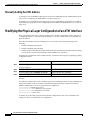
Verifying Software and Hardware Installed on the ATM Switch Router
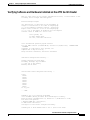
When you first power up your console and ATM switch router, a screen similar to the
following from a Catalyst 8540 MSR appears:
Restricted Rights Legend
Use, duplication, or disclosure by the Government is
subject to restrictions as set forth in subparagraph
(c) of the Commercial Computer Software - Restricted
Rights clause at FAR sec. 52.227-19 and subparagraph
(c) (1) (ii) of the Rights in Technical Data and Computer
Software clause at DFARS sec. 252.227-7013.
cisco Systems, Inc.
170 West Tasman Drive
San Jose, California 95134-1706
Cisco Internetwork Operating System Software
IOS (tm) PNNI Software (cat8540m-WP-M), Version 12.0(4a)W5(10.44),
SOFTWARE
Copyright (c) 1986-1999 by cisco Systems, Inc.
Compiled Tue 17-Aug-99 03:18 by
Image text-base: 0x60010930, data-base: 0x60936000
INTERIM TEST
CUBI Driver subsystem initializing ...
primary interrupt reg read FFC00
secondary interrupt reg read EA800
*** this cpu is the primary
Enabling the MS timer
Switch Fabric Driver subsystem initializing ...
found
smid=0
smid=2
smid=4
smid=6
smid=1
smid=3
smid=5
smid=7
in cfc_init
... DONE
IDPROM in slot 0 not properly programmed
cisco C8540MSR (R5000) processor with 262144K bytes of memory.
R5000 processor, Implementation 35, Revision 2.1 (512KB Level 2 Cache)
Last reset from power-on
3 Ethernet/IEEE 802.3 interface(s)
11 ATM network interface(s)
507K bytes of non-volatile configuration memory.
20480K bytes of Flash PCMCIA card at slot 0 (Sector size 128K).
ATM Switch Router Software Configuration Guide
78-6277-03, Cisco IOS Release 12.0(13)W5(19)
3-3
Chapter 3
Initially Configuring the ATM Switch Router
Configuring the BOOTP Server
8192K bytes of Flash PCMCIA card at slot 1 (Sector size 128K).
8192K bytes of Flash internal SIMM (Sector size 256K).
%ENABLING INTERFACES.PLEASE WAIT...
%Secondary CPU has not booted IOS
Press RETURN to get started!
Note
If an rommon> prompt appears, your switch requires a manual boot to recover. Refer to
the Configuration Fundamentals Configuration Guide for instructions on manually
booting from Flash memory.
Configuring the BOOTP Server
The BOOTP protocol automatically assigns an Ethernet IP address by adding the MAC and IP addresses
of the Ethernet port to the BOOTP server configuration file. When the switch boots, it automatically
retrieves the IP address from the BOOTP server.
The switch performs a BOOTP request only if the current IP address is set to 0.0.0.0. (This is the default
for a new switch or a switch that has had its startup-config file cleared using the erase command.)
To allow your ATM switch router to retrieve its IP address from a BOOTP server, you must first
determine the MAC address of the switch and add that MAC address to the BOOTP configuration file
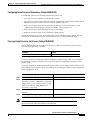
on the BOOTP server. The following steps provide an example of creating a BOOTP server
configuration file:
Command
Purpose
Step 1
—
Installs the BOOTP server code on the workstation, if it is not
already installed.
Step 2
—
Determines the MAC address from the label on the chassis.
Step 3
—
Adds an entry in the BOOTP configuration file (usually
/usr/etc/bootptab) for each switch. Press Return after each entry
to create a blank line between each entry. See the example
BOOTP configuration file that follows.
Step 4
Switch# reload
Restarts the ATM switch router to automatically request the
IP address from the BOOTP server.
ATM Switch Router Software Configuration Guide
3-4
78-6277-03, Cisco IOS Release 12.0(13)W5(19)
Chapter 3
Initially Configuring the ATM Switch Router
Configuring the ATM Address
Example
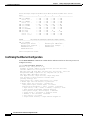
The following example BOOTP configuration file shows the added entry:
# /etc/bootptab: database for bootp server (/etc/bootpd)
#
# Blank lines and lines beginning with '#' are ignored.
#
# Legend:
#
#
first field -- hostname
#
(may be full domain name and probably should be)
#
#
hd -- home directory
#
bf -- bootfile
#
cs -- cookie servers
#
ds -- domain name servers
#
gw -- gateways
#
ha -- hardware address
#
ht -- hardware type
#
im -- impress servers
#
ip -- host IP address
#
lg -- log servers
#
lp -- LPR servers
#
ns -- IEN-116 name servers
#
rl -- resource location protocol servers
#
sm -- subnet mask
#
tc -- template host (points to similar host entry)
#
to -- time offset (seconds)
#
ts -- time servers
#
<information deleted>
#
#########################################################################
# Start of individual host entries
#########################################################################
Switch:
tc=netcisco0:
ha=0000.0ca7.ce00:
ip=172.31.7.97:
dross:
tc=netcisco0:
ha=00000c000139:
ip=172.31.7.26:
<information deleted>
Configuring the ATM Address
The ATM switch router ships with a preconfigured ATM address. The Integrated Local Management
Interface (ILMI) protocol uses the first 13 bytes of this address as the switch prefix that it registers with
end systems. Autoconfiguration also allows the ATM switch router to establish itself as a node in a
single-level Private Network-Network Interface (PNNI) routing domain.
Note
If you chose to manually change any ATM address, it is important to maintain the
uniqueness of the address across large networks. Refer to the Guide to ATM Technology
for PNNI address considerations and for information on obtaining registered ATM
addresses.
For a description of the autoconfigured ATM address and considerations when assigning a new address,
refer to the Guide to ATM Technology.
ATM Switch Router Software Configuration Guide
78-6277-03, Cisco IOS Release 12.0(13)W5(19)
3-5
Chapter 3
Initially Configuring the ATM Switch Router
Modifying the Physical Layer Configuration of an ATM Interface
Manually Setting the ATM Address
To configure a new ATM address that replaces the previous ATM address when running IISP software
only, see the “Configuring the ATM Address” section on page 10-5.
To configure a new ATM address that replaces the previous ATM address and generates a new PNNI
node ID and peer group ID, see the “Configuring an ATM Address and PNNI Node Level” section on
page 10-10.
Modifying the Physical Layer Configuration of an ATM Interface
Each of the ATM switch router’s physical interfaces has a default configuration, listed in Chapter 17,
“Configuring Interfaces.” You can accept the defaults, or you can override them by reconfiguring the
physical interface.
The following example describes modifying an OC-3c interface from the default settings to the
following:
•
Disable scrambling cell-payload.
•
Disable scrambling STS-streaming.
•
Change Synchronous Optical Network (SONET) mode of operation from Synchronous Time Stamp
level 3c (STS-3c) mode to Synchronous Transfer Module level 1 (STM-1).
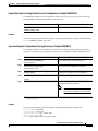
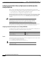
To change the configuration of the example interface, perform the following steps, beginning in global
configuration mode:
Command
Step 1
Purpose
Switch(config)# interface atm card/subcard/port Selects the physical interface to be configured.
Switch(config-if)#
Step 2
Switch(config-if)# no scrambling cell-payload
Disables cell-payload scrambling.
Step 3
Switch(config-if)# no scrambling sts-stream
Disables STS-stream scrambling.
Step 4
Switch(config-if)# sonet stm-1
Configures SONET mode as SDH/STM-1.
Example
The following example shows how to disable cell-payload scrambling and STS-stream scrambling and
changes the SONET mode of operation to Synchronous Digital Hierarchy/Synchronous Transfer
Module 1 (SDH/STM-1) of OC-3c physical interface ATM 0/0/0:
Switch(config)# interface atm 0/0/0
Switch(config-if)# no scrambling cell-payload
Switch(config-if)# no scrambling sts-stream
Switch(config-if)# sonet stm-1
To change any of the other physical interface default configurations, refer to the commands in the
ATM Switch Router Command Reference publication.
ATM Switch Router Software Configuration Guide
3-6
78-6277-03, Cisco IOS Release 12.0(13)W5(19)
Chapter 3
Initially Configuring the ATM Switch Router
Configuring the IP Interface
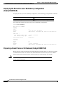
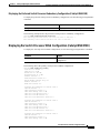
To display the physical interface configuration, use the following privileged EXEC commands:
Command
Purpose
show controllers atm card/subcard/port
Shows the physical layer configuration.
more system:running-config
Shows the physical layer scrambling
configuration.
Examples
The following example demonstrates using the show controllers command to display the OC-3c
physical interface configuration after modification of the defaults:
Switch# show controllers atm 0/0/0
IF Name: ATM0/0/0
Chip Base Address: A8808000
Port type: 155UTP
Port rate: 155 Mbps
Port medium: UTP
Port status:SECTION LOS
Loopback:None
Flags:8300
TX Led: Traffic Pattern
RX Led: Traffic Pattern TX clock source:
Framing mode: stm-1
Cell payload scrambling off
Sts-stream scrambling off
network-derived
<information deleted>
The following example displays the OC-3c physical layer scrambling configuration after modification
of the defaults using the more system:running-config command:
Switch# more system:running-config
!
version XX.X
<information deleted>
!
interface ATM0/0/0
no keepalive
atm manual-well-known-vc
atm access-group tod1 in
atm pvc 0 35 rx-cttr 3 tx-cttr 3 interface
sonet stm-1
no scrambling sts-stream
no scrambling cell-payload
!
<information deleted>
ATM0 0 any-vci
encap qsaal
Configuring the IP Interface
IP addresses can be configured on the multiservice route processor interfaces. Each IP address is
configured for one of the following types of connections:
•
Ethernet port—Can be configured either from the BOOTP server or by using the ip address
command in interface configuration mode.
•
Classical IP over ATM—See Chapter 12, “Configuring IP over ATM.”
•
LANE client—See Chapter 13, “Configuring LAN Emulation.”
•
Serial Line Internet Protocol/Point-to-Point Protocol (SLIP/PPP)—See the Dial Solutions
Configuration Guide.
ATM Switch Router Software Configuration Guide
78-6277-03, Cisco IOS Release 12.0(13)W5(19)
3-7
Chapter 3
Initially Configuring the ATM Switch Router
Configuring the IP Interface
Note
These IP connections are used only for network management.
To configure the switch to communicate via the Ethernet interface, provide the IP address and subnet
mask bits for the interface.
This section includes the following:
•
Configuring IP Address and Subnet Mask Bits on page 3-8
•
Testing the Ethernet Connection on page 3-9
Configuring IP Address and Subnet Mask Bits
Define subnet mask bits as a decimal number between 0 and 22 for Class A addresses, between 0 and 14
for Class B addresses, or between 0 and 6 for Class C addresses. Do not specify 1 as the number of bits
for the subnet field. That specification is reserved by Internet conventions.
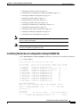
To configure the IP address, perform the following steps, beginning in global configuration mode:
Step 1
Command
Purpose
Switch(config)# interface ethernet 0
Selects the interface to be configured.
Switch(config-if)#
Step 2
Switch(config-if)# ip address ip-address mask
Note
Since release 12.0(1a)W5(5b) of the ATM switch software, addressing the interface on the
processor (CPU) has changed. The ATM interface is now called atm 0, and the Ethernet
interface is now called ethernet 0. The old formats (atm 2/0/0 and ethernet 2/0/0) are still
supported.
Configures the IP and subnetwork address.
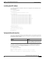
Example
The following example shows how to configure interface ethernet 0 with IP address 172.20.40.93 and
subnetwork mask 255.255.255.0:
Switch(config)# interface ethernet 0
Switch(config-if)# ip address 172.20.40.93 255.255.255.0
Displaying the IP Address
To display the IP address configuration, use the following privileged EXEC commands:
Command
Purpose
show interfaces ethernet 0
Displays the Ethernet interface IP address.
more system:running-config
Shows the physical layer scrambling
configuration.
ATM Switch Router Software Configuration Guide
3-8
78-6277-03, Cisco IOS Release 12.0(13)W5(19)
Chapter 3
Initially Configuring the ATM Switch Router
Configuring the IP Interface
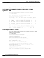
Examples
The following example shows how to use the show interfaces command to display the IP address of
interface ethernet 0:
Switch# show interfaces ethernet 0
Ethernet0 is up, line protocol is up
Hardware is SonicT, address is 0040.0b0a.1080 (bia 0040.0b0a.1080)
Internet address is 172.20.40.93/24
<information deleted>
The following example uses the more system:running-config command to display the IP address of
interface ethernet 0:
Switch# more system:running-config
!
version XX.X
<information deleted>
!
interface Ethernet0
ip address 172.20.40.93 255.255.255.0
!
<information deleted>
Testing the Ethernet Connection
After you have configured the IP address(es) for the Ethernet interface, test for connectivity between
the switch and a host. The host can reside anywhere in your network. To test for Ethernet connectivity,
use the following EXEC command:
Command
Purpose
ping ip ip-address
Tests the configuration using the ping command. The ping
command sends an echo request to the host specified in the
command line.
The following example show how to test the Ethernet connectivity from the switch to a workstation with
an IP address of 172.20.40.201:
Switch# ping ip 172.20.40.201
Type escape sequence to abort.
Sending 5, 100-byte ICMP Echos to 172.20.40.201, timeout is 2 seconds:
!!!!!
Success rate is 100 percent (5/5), round-trip min/avg/max = 1/202/1000 ms
ATM Switch Router Software Configuration Guide
78-6277-03, Cisco IOS Release 12.0(13)W5(19)
3-9
Chapter 3
Initially Configuring the ATM Switch Router
Configuring Network Clocking
Configuring Network Clocking
This section describes network clocking configuration of the ATM switch router. Properly
synchronized network clocking is important in the transmission of constant bit rate (CBR) and variable
bit rate real time (VBR-RT) data. For an overview of network clocking and network clock configuration
issues, refer to the chapter “Network Clock Synchronization” in the Guide to ATM Technology.
This section includes the following:
•
Configuring Network Clock Sources and Priorities (Catalyst 8540 MSR) on page 3-11
•
Configuring Network Clock Sources and Priorities (Catalyst 8510 MSR and LightStream 1010) on
page 3-12
•
Displaying the Network Clocking Configuration on page 3-13
•
Configuring Network Clocking with NCDP on page 3-14
•
Network Clock Services for CES Operations and CBR Traffic on page 3-17
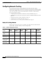
Network Clocking Features
Different types of network clock sources are available on the ATM switch router, both internal and
external. Table 3-1 provides a summary of network clocking features.
Table 3-1
Network Clocking Feature Summary
Loss of
Phase
Synchronization Adjustment
Detection
Cutover
Stratum 3
Clock
BITS1 Port
Clock Source
Preference
Catalyst 8540 MSR Yes
with network clock
module
Yes
Yes
Yes
Yes
Best
Catalyst 8510 MSR Yes
Yes
Yes
No
No
Medium
LightStream 1010
with FC-PFQ
Yes
Yes
Yes
No
No
Medium
Catalyst 8540 MSR Yes
without network
clock module
No
No
No
No
Poor
LightStream 1010
with FC-PCQ
No
No
No
No
Poor
Up/Down
Detection
Platform
Yes
1. BITS = Building Integrated Timing Supply
ATM Switch Router Software Configuration Guide
3-10
78-6277-03, Cisco IOS Release 12.0(13)W5(19)
Chapter 3
Initially Configuring the ATM Switch Router
Configuring Network Clocking
Configuring Network Clock Sources and Priorities (Catalyst 8540 MSR)
To configure the network clocking priorities and sources, use the following command in global
configuration mode:
Note
Command
Purpose
network-clock-select {priority {{atm | cbr}
card/subcard/port} | bits {0 | 1} | system} |
bits {e1 | t1} | revertive
Configures the network clock priority.
Specifying the keyword system with the network-clock-select command selects the
route processor reference clock (a stratum 4 clock source) or the network clock module (a
stratum 3 clock source), if present.
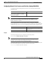
Systems equipped with the network clock module can derive clocking from a Building Integrated
Timing Supply (BITS) source. To specify the line type attached to the BITS ports on the network clock
module and to assign a priority to a port, use the following commands in global configuration mode:
Command
Purpose
network-clock-select bits {t1 | e1}
Selects the line type. This command applies to
both BITS ports.
network-clock-select priority bits {0 | 1}
Selects the priority for a BITS port.
Examples
The following example shows how to configure the network clock priorities:
Switch(config)# network-clock-select 1 atm 0/0/0
Switch(config)# network-clock-select 2 atm 0/0/3
Note
This configuration assumes that a full-width module, such as the 4-port OC-12c module,
is being used to derive clocking. If port adapters inserted into carrier modules are used,
the priority 1 and 2 source ports must be on different port adapters.
The following example shows how to configure the network clock to revert to the highest priority clock
source after a failure and takeover by the source with the next lowest priority.
Switch(config)# network-clock-select revertive
ATM Switch Router Software Configuration Guide
78-6277-03, Cisco IOS Release 12.0(13)W5(19)
3-11
Chapter 3
Initially Configuring the ATM Switch Router
Configuring Network Clocking
Configuring Network Clock Sources and Priorities (Catalyst 8510 MSR and
LightStream 1010)
To configure the network clocking priorities and sources, use the following command in global
configuration mode:
Note
Command
Purpose
network-clock-select {priority {{atm | cbr}
card/subcard/port} | system} | revertive
Configures the network clock priority.
Specifying the keyword system with the network-clock-select command selects the
processor card reference clock (a stratum 4 clock source).
Examples
The following example shows how to configure the network clock priorities:
Switch(config)# network-clock-select 1 atm 0/0/0
Switch(config)# network-clock-select 2 atm 0/0/3
The following example shows how to configure the network clock to revert to the highest priority clock
source after a failure and takeover by the source with the next lowest priority.
Switch(config)# network-clock-select revertive
Configuring the Transmit Clocking Source
To configure where each interface receives its transmit clocking, perform the following steps, beginning
in global configuration mode:
Command
Step 1
Purpose
Switch(config)# interface atm card/subcard/port Selects the interface to be configured.
Switch(config-if)#
Step 2
Caution
Switch(config-if)# clock source {free-running |
loop-timed | network-derived}
Configures the interface clock source.
If the Network Clock Distribution Protocol (NCDP) is running on an interface, you should
not override that port’s clock source by configuring it to free-running or loop-timed. Doing
so could cause synchronization problems, particularly in the case of loop-timed, which
could cause a clocking loop to be formed on a link. See the “Configuring Network
Clocking with NCDP” section on page 3-14.
ATM Switch Router Software Configuration Guide
3-12
78-6277-03, Cisco IOS Release 12.0(13)W5(19)
Chapter 3
Initially Configuring the ATM Switch Router
Configuring Network Clocking
Example
The following example configures ATM interface 3/0/0 to receive its transmit clocking from a
network-derived source:
Switch(config)# interface atm 3/0/0
Switch(config-if)# clock source network-derived
Displaying the Network Clocking Configuration
To show the switch’s network clocking configuration, use the following privileged EXEC commands:
Command
Purpose
show network-clocks
Shows the network clocking configuration.
more system:running-config
Shows the interface clock source configuration.
show controllers [atm card/subcard/port]
Shows the interface controller status.
Examples
The following example shows the configured network clock sources on a Catalyst 8510 MSR or
LightStream 1010:
Switch# show network-clocks
clock configuration is NON-Revertive
Priority 1 clock source: ATM1/0/0
Priority 2 clock source: ATM1/1/0
Priority 3 clock source: No clock
Priority 4 clock source: No clock
Priority 5 clock source: System clock
Current clock source:System clock, priority:5
Note
A source listed as “No clock” indicates that no clock source configured at that priority.
The following example shows the switch clock source configuration with the network clock module
installed:
Switch# show network-clocks
Network clocking information:
--------------------------------------Source switchover mode:
revertive
Netclkd state:
Active
Source selection method:
provisioned
NCLKM hardware status:
installed & usable
NCLKM status:
software enabled
Primary
clock source:
ATM0/0/0
Secondary clock source:
not configured
Present
clock source:
NCLKM Stratum 3 osc (0)
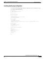
The following example shows the clock source configuration stored in the running configuration:
Switch# more system:running-config
!
<information deleted>
!
network-clock-select revertive
network-clock-select 1 ATM0/0/0
<information deleted>
ATM Switch Router Software Configuration Guide
78-6277-03, Cisco IOS Release 12.0(13)W5(19)
3-13
Chapter 3
Initially Configuring the ATM Switch Router
Configuring Network Clocking
Configuring Network Clocking with NCDP
The Network Clock Distribution Protocol (NCDP) provides a means by which a network can
synchronize automatically to a primary reference source (PRS). To do so, NCDP constructs and
maintains a spanning network clock distribution tree. This tree structure is superimposed on the network
nodes by the software, resulting in an efficient, synchronized network suitable for transport of traffic
with inherent synchronization requirements, such as voice and video.
The following sections provide instructions for configuring NCDP. For a description of how NCDP
works, refer to the Guide to ATM Technology.
Note
The NCDP is intended for use on ATM switch routers equipped with FC-PFQ or with the
network clock module.
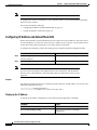
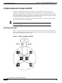
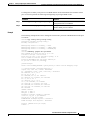
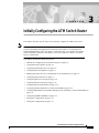
NCDP Network Example
Figure 3-1 shows a network of six ATM switch routers with clocking derived from a stratum 3 PRS.
Node A is configured to receive priority 1 clocking on two of its ports, while node B is configured to
receive priority 2 clocking on one of its ports.
Figure 3-1
Network Configuration for NCDP
PRS
source
Priority 2
Stratum 3
Priority 1
Stratum 3
C
D
A
F
23985
E
B
ATM Switch Router Software Configuration Guide
3-14
78-6277-03, Cisco IOS Release 12.0(13)W5(19)
Chapter 3
Initially Configuring the ATM Switch Router
Configuring Network Clocking
Enabling NCDP
To enable NCDP, use the following global configuration command for each node that you want to
configure for NCDP:
Command
Purpose
ncdp
Enables NCDP.
Configuring Network Clock Sources and Priorities
You must specify the clocking sources, their priorities, and associated stratums used by NCDP in
constructing the clock distribution tree. To do so, use the following command in global configuration
mode:
Command
Purpose
ncdp source priority {{atm | cbr}
card/subcard/port stratum | bits1 {0 | 1}
stratum | system}
Specifies a priority and source (stratum level
or system) for this interface.
1. Allows you to specify a Building Integrated Timing Supply (BITS) source. This option is available only on the
Catalyst 8540 MSR equipped with the network clock module.
If you do not configure a clock source, NCDP advertises its default source of network clock, which is
its local oscillator; if no nodes in the network have a clock source configured, the tree is built so that it
is rooted at the switch having the highest stratum oscillator (lowest numerical value) and lowest ATM
address.
Example
The following example demonstrates configuring the network clock source, priority, and stratum on
node A in Figure 3-1.
Switch(config)# ncdp source 1 atm 1/0/0 3
Switch(config)# ncdp source 1 atm 3/0/0 3
Configuring Optional NCDP Global Parameters
Optional NCDP parameters you can configure at the global level include the maximum number of hops
between any two nodes, revertive behavior, and the values of the NCDP timers. To change any of these
parameters from their defaults, use the following commands in global configuration mode:
Command
Purpose
ncdp max-diameter hops
Specifies the maximum network diameter for the
protocol. The default maximum network diameter
is 20.
ncdp revertive
Specifies the NCDP as revertive.
ncdp timers {hello | hold} time-in-msec Specifies the values to be used by the NCDP
jitter-percent
timers.
ATM Switch Router Software Configuration Guide
78-6277-03, Cisco IOS Release 12.0(13)W5(19)
3-15
Chapter 3
Initially Configuring the ATM Switch Router
Configuring Network Clocking
When you specify a maximum diameter, you constrain the diameter of the spanning tree by specifying
the maximum number of hops between any two nodes that participate in the protocol. Each node must
be configured with the same maximum network diameter value for NCDP to operate correctly.
When you configure the NCDP as revertive, a clock source that is selected and then fails is selected
again once it has become operational for a period of time. On the Catalyst 8510 MSR and
LightStream 1010 platforms, if NCDP is configured to be revertive, a failed clocking source node after
a switchover is restored to use after it has been functioning correctly for at least 1 minute. On the
Catalyst 8540 MSR the failed source is restored after about 25 seconds. The network clock is, by
default, configured as nonrevertive. Nonrevertive prevents a failed source from being selected again.
Example
The following example shows setting the maximum number of hops to 11 and enabling revertive
behavior:
Switch(config)# ncdp max-diameter 11
Switch(config)# ncdp revertive
Configuring Optional NCDP Per-Interface Parameters
On a per-interface basis, you can enable or disable NCDP, specify the cost metric associated with the
port, and change the control virtual circuit used to transport protocol messages between adjacent
protocol entities. To change any of these parameters from their defaults, use the following commands
in interface configuration mode:
Command
Purpose
ncdp admin-weight weight
Specifies the cost metric associated with the given
port.
ncdp control-vc vpi vci
Specifies the VPI/VCI values to use for control VCs.
The default is 0, 34.
no ncdp
Disables NCDP on the interface.
Example
The following example demonstrates setting the administrative weight on an interface:
Switch(config)# interface atm 0/0/0
Switch(config-if)# ncdp admin-weight 75
Displaying the NCDP Configuration
To display the NCDP configuration, use the following EXEC commands:
Command
Purpose
show ncdp path root
Displays the NCDP clock path from the switch to the
root source.
show ncdp ports
Displays NCDP port information.
show ncdp sources
Displays NCDP clock sources configured on the
switch.
ATM Switch Router Software Configuration Guide
3-16
78-6277-03, Cisco IOS Release 12.0(13)W5(19)
Chapter 3
Initially Configuring the ATM Switch Router
Configuring Network Clocking
Command
Purpose
show ncdp status
Displays NCDP status.
show ncdp timers
Displays NCDP timer information.
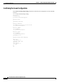
Example
The following example shows the NCDP status:
Switch# show ncdp status
= ncdp switch information ==== enabled ==============
non-revertive
root clock source priority:
1
root clock source stratum level: 4
root clock source prs id:
255
stratum level of root switch:
4
clocking root address:
4700918100000000E0F75D040100E0F75D040100
hop count:
0
root path cost:
0
root port:
0
max age:
5
hello time:
500
priority
of best source:
1
stratum level of best source:
4
prs id
of best source:
255
switch stratum level:
4
address:
4700918100000000E0F75D040100E0F75D040100
switch max age:
5
switch hello time:
500
switch hold time:
500
max diameter:
5
converged root count:
359375
converged:
1
total timer events:
687271
total queue events:
0
rx config messages:
0
tx config messages:
363716
rx tcn messages:
0
tx tcn messages:
0
rx non-participant messages:
0
rx unknown messages:
0
Switch#
Network Clock Services for CES Operations and CBR Traffic
Circuit emulation services-interworking functions (CES-IWF) and constant bit rate (CBR) traffic relate
to a quality of service (QoS) classification defined by the ATM Forum for Class A (ATM adaptation
layer 1 [AAL1]) traffic in ATM networks. In general, Class A traffic pertains to voice and video
transmissions, which have particular clocking requirements. For details, refer to Chapter 18,
“Configuring Circuit Emulation Services.”
ATM Switch Router Software Configuration Guide
78-6277-03, Cisco IOS Release 12.0(13)W5(19)
3-17
Chapter 3
Initially Configuring the ATM Switch Router
Configuring Network Routing
Configuring Network Routing
The default software image for the ATM switch router contains the Private Network-Network Interface
(PNNI) routing protocol. The PNNI protocol provides the route dissemination mechanism for complete
plug-and-play capability. The following section, “Configuring ATM Static Routes for IISP or PNNI,”
describes modifications that can be made to the default PNNI or Interim-Interswitch Signalling Protocol
(IISP) routing configurations.
For routing protocol configuration information, refer to Chapter 9, “Configuring ILMI,”and Chapter 10,
“Configuring ATM Routing and PNNI.”
Configuring ATM Static Routes for IISP or PNNI
Static route configuration allows ATM call setup requests to be forwarded on a specific interface if the
addresses match a configured address prefix. To configure a static route, use the following command in
global configuration mode:
Note
Command
Purpose
atm route addr-prefx atm card/subcard/port
Specifies a static route to a reachable address
prefix.
An interface must be User-Network Interface (UNI) or Interim Interswitch Signalling
Protocol (IISP) to be configured with static route. Static routes configured as PNNI
interfaces default as down.
The following example shows how to use the atm route command to configure the 13-byte peer group
prefix = 47.0091.8100.567.0000.0ca7.ce01 at interface ATM 3/0/0:
Switch(config)# atm route 47.0091.8100.567.0000.0ca7.ce01 atm 3/0/0
Switch(config)#
Configuring System Information
Although not required, the system clock and hostname should be set as part of the initial system
configuration. To set these system parameters, perform the following steps, beginning in privileged
EXEC mode:
Command
Purpose
Step 1
Switch# clock set hh:mm:ss day month year
Sets the system clock.
Step 2
Switch# configure terminal
Switch(config)#
Enters global configuration mode from the
terminal.
Switch(config)# hostname name
Sets the system name.
Step 3
ATM Switch Router Software Configuration Guide
3-18
78-6277-03, Cisco IOS Release 12.0(13)W5(19)
Chapter 3
Initially Configuring the ATM Switch Router
Configuring Online Diagnostics (Catalyst 8540 MSR)
Examples
The following example shows how to configure the time, date, and month using the clock set command,
enter global configuration mode, and assign a hostname.
Switch# clock set 15:01:00 17 October 1999
Switch# configure terminal
Enter configuration commands, one per line.
Switch(config)# hostname Publications
Publications#
End with CNTL/Z.
The following example shows how to confirm the clock setting using the show clock command:
Publications# show clock
*15:03:12.015 UTC Fri Oct 17 1999
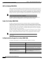
Configuring Online Diagnostics (Catalyst 8540 MSR)
Online and insertion diagnostics detect and report hardware failures in the Catalyst 8540 MSR during
system bootup and operation.
The online diagnostics on the Catalyst 8540 MSR provide the following types of tests:
Note
•
Access tests between the route processor and the switch processors, feature cards, port adapters,
and interface modules
•
Online insertion and removal (OIR) diagnostic tests
•
Snake tests through the switch router to ensure connectivity between the ports
Online diagnostics tests only run on the primary route processor.
Access Test (Catalyst 8540 MSR)
The access tests ensure connectivity at a configurable interval between the primary route processor and
the following:
•
Active switch processors
•
Standby switch processor, if it is present
•
Feature cards
•
Carrier modules
•
ATM port adapters
•
ATM and Layer 3 interface modules
•
ATM router modules
When the access test detects a hardware failure, the system issues an error message to the console.
If the access test detects a hardware problem with an active switch processor, the standby switch
processor, if it is present, automatically takes over and becomes an active switch processor. The system
generates an SNMP trap when the switchover occurs.
Note
The access test does not support the network clock module.
ATM Switch Router Software Configuration Guide
78-6277-03, Cisco IOS Release 12.0(13)W5(19)
3-19
Chapter 3
Initially Configuring the ATM Switch Router
Configuring Online Diagnostics (Catalyst 8540 MSR)
OIR Test (Catalyst 8540 MSR)
Online insertion and removal (OIR) tests check the functioning of the switch fabric and interfaces on a
per-port basis. The switch router performs these tests when the system boots up and when you insert a
port adapter or interface module into a slot. The OIR test sends a packet to the interface loopback and
expects to receive it back within a certain time period. If the packet does not reach the port within the
expected time period, or the route processor receives a corrupted packet, the system issues an error
message to the console, generates an SNMP trap, and brings the port to an administrative down state.
Note
The size of the packet used in the test is configurable.
The OIR tests support all ATM port adapters, all ATM interface modules, and all Layer 3 interface
modules except the 8-port Gigabit Ethernet. It does not support ATM router modules.
Snake Test (Catalyst 8540 MSR)
The snake test detects and reports port-to-port connectivity failures. The snake test establishes a
connection across all the active ports in the switch router, originating and terminating at the primary
route processor. The route processor establishes a connection by sending a packet to each port in turn,
which then terminates at the route processor. If the packet does not reach the route processor within the
expected time period, or the received packet is corrupted, further testing is performed to isolate and
disable the port causing the problem.The size of the packet and frequency of the test are configurable
to minimize the impact on system performance.
The snake test supports all ATM interface modules and enhanced Gigabit Ethernet interface modules.
It does not support ATM port adapters, ATM router modules, 16-port 10/100 Fast Ethernet interface
modules, 2-port Gigabit Ethernet interface modules, or 8-port Gigabit Ethernet interface modules.
Note
The snake test does not support ATM port adapters because of a hardware limitation in the
carrier module.
Configuring Online Diagnostics (Catalyst 8540 MSR)
To configure online diagnostics, use the following global configuration commands:
Command
Purpose
diag online
Enables all of the online diagnostic tests.
diag online access
Enables only the access diagnostic test.
diag online access freq [seconds]
Configures the frequency of the access diagnostic
tests. The default frequency is every 10 seconds.
diag online oir
Enables only the OIR test.
diag online oir pktsize [bytes]
Specifies the packet size for the OIR test. The
default size is 1000 bytes.
diag online snake
Enables only the snake test.
ATM Switch Router Software Configuration Guide
3-20
78-6277-03, Cisco IOS Release 12.0(13)W5(19)
Chapter 3
Initially Configuring the ATM Switch Router
Configuring Online Diagnostics (Catalyst 8540 MSR)
Command
Purpose
diag online snake timer [seconds]
Specifies the time interval for the snake test. The
default interval is 60 seconds.
no diag online [access | oir | snake]
Disables the online diagnostic tests.
debug diag online [access | oir | snake]
Enables debugging of online diagnostic tests.
no debug diag online [access | oir | snake]
Disables debugging of online diagnostic tests.
Examples
The following example shows how to enable all online diagnostic tests:
Switch(config)# diag online
ONLINE-DIAG: Enabling all Online Diagnostics tests
The following example shows how to change the frequency of the access test to 20 seconds:
Switch(config)# diag online access freq 20
ONLINE-DIAG: Online Access Test Frequency set to 20 sec
Displaying the Online Diagnostics Configuration and Results (Catalyst 8540 MSR)
To display the online diagnostics configuration and results, use the following EXEC command:
Command
Purpose
show diag online [details | status] [access | oir |
snake]
Displays information about the online
diagnostics test configuration and the test results.
Examples
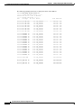
The following example shows how to display detailed access test configuration and results:
Switch# show diag online details access
======== Online Access Test Details ========
Current Test Status : Test is Enabled
Current Frequency of Access Test : 20 seconds
Slot Card-Type
Iteration
Success
Failure
---- ------------------------------0/* Super Cam
42998
42998
0
0/0 8T1 IMA PAM
42998
42998
0
0/1 8E1 IMA PAM
42998
42998
0
2/* ARM PAM
42998
42998
0
3/* ETHERNET PAM
42998
42998
0
5/* Switch Card
42998
42998
0
5/0 Feature Card
42998
42998
0
7/* Switch Card
42998
42998
0
7/0 Feature Card
42998
42998
0
9/* OC48c PAM
42998
42998
0
10/* OCM Board
42998
42998
0
10/0 QUAD 622 Generi 42998
42998
0
======== Online Access Test Details End ========
Last Failure
------------------------------------------------
ATM Switch Router Software Configuration Guide
78-6277-03, Cisco IOS Release 12.0(13)W5(19)
3-21
Chapter 3
Initially Configuring the ATM Switch Router
Configuring Online Diagnostics (Catalyst 8540 MSR)
The following example shows how to display the status of the OIR test:
Switch# show diag online status oir
======== Online OIR Test Status ========
Current Test Status : Test is Enabled
-------- Bootup OIR status -------Port
Card Type
Pkt Size Result
_______ ___________ _________ ___________________
00/0/00 8T1 IMA PAM
300 OIR_SUCCESS
00/0/01 8T1 IMA PAM
300 OIR_SUCCESS
00/0/02 8T1 IMA PAM
300 OIR_SUCCESS
00/0/03 8T1 IMA PAM
300 OIR_SUCCESS
00/1/00 8E1 IMA PAM
300 OIR_SUCCESS
00/1/01 8E1 IMA PAM
300 OIR_SUCCESS
00/1/02 8E1 IMA PAM
300 OIR_SUCCESS
00/1/03 8E1 IMA PAM
300 OIR_SUCCESS
03/0/00
03/0/01
03/0/02
03/0/03
03/0/04
03/0/05
03/0/06
03/0/07
03/0/08
03/0/09
03/0/10
03/0/11
03/0/12
03/0/13
03/0/14
03/0/15
ETHERNET
ETHERNET
ETHERNET
ETHERNET
ETHERNET
ETHERNET
ETHERNET
ETHERNET
ETHERNET
ETHERNET
ETHERNET
ETHERNET
ETHERNET
ETHERNET
ETHERNET
ETHERNET
PA
PA
PA
PA
PA
PA
PA
PA
PA
PA
PA
PA
PA
PA
PA
PA
1000
1000
1000
1000
1000
1000
1000
1000
1000
1000
1000
1000
1000
1000
1000
1000
OIR_SUCCESS
OIR_SUCCESS
OIR_SUCCESS
OIR_SUCCESS
OIR_SUCCESS
OIR_SUCCESS
OIR_SUCCESS
OIR_SUCCESS
OIR_SUCCESS
OIR_SUCCESS
OIR_SUCCESS
OIR_SUCCESS
OIR_SUCCESS
OIR_SUCCESS
OIR_SUCCESS
OIR_SUCCESS
Test Time LOOP
______________ ____
00:00:41 PIF
00:00:41 PIF
00:00:41 PIF
00:00:41 PIF
00:00:41 PIF
00:00:46 PIF
00:00:41 PIF
00:00:46 PIF
00:01:54
00:01:52
00:01:50
00:01:48
00:01:55
00:01:53
00:01:51
00:01:49
00:02:02
00:02:00
00:01:58
00:01:56
00:02:03
00:02:01
00:01:59
00:01:57
PIF
PIF
PIF
PIF
PIF
PIF
PIF
PIF
PIF
PIF
PIF
PIF
PIF
PIF
PIF
PIF
09/0/00 OC48c PAM
300 OIR_SUCCESS
00:00:46 Both
10/0/00
10/0/01
10/0/02
10/0/03
300
300
300
300
00:00:46
00:00:46
00:00:46
00:00:46
QUAD
QUAD
QUAD
QUAD
622
622
622
622
Ge
Ge
Ge
Ge
OIR_SUCCESS
OIR_SUCCESS
OIR_SUCCESS
OIR_SUCCESS
Both
Both
Both
Both
ATM Switch Router Software Configuration Guide
3-22
78-6277-03, Cisco IOS Release 12.0(13)W5(19)
Chapter 3
Initially Configuring the ATM Switch Router
Configuring Redundancy and Enhanced High System Availability (Catalyst 8540 MSR)
The following example shows how to display the details and status of the snake test:
8540MSR#show diag online snake
======== Online Snake Test Status and Details ========
-------- Test Status -------Current Test Status
: Test is Enabled
Current Test Type
: Normal Snake
Last Test Status
: Pass
Last Test Run Time
: 1w1d
Last Test Success Time : 1w1d
-------- Test Details
Snake Test Pkt Size
Default Test Period
Current Test Period
-------: 30 bytes
: 60 seconds
: 60 seconds
---------------------------------Statistics from Bootup
---------------------------------Total Test Runs
Number Normal Snake Test Runs
Number of Successive Normal Snake Test
Number of Incrimental Snake Test Runs
:
:
:
:
17311
17311
14083
0
-----------------------------------------Ports Test Stat in Last Iteration
-----------------------------------------Port
_______
09/0/00
10/0/00
11/0/00
12/0/00
Card Type
________________
OC48c PAM
QUAD 622 Generic
OC48c PAM
QUAD 622 Generic
Result
__________
PORT_OK
PORT_OK
PORT_OK
PORT_OK
Test Time
_________
1w1d
1w1d
1w1d
1w1d
----------------------------------------Ports Failed Stat from Bootup
----------------------------------------No Port failed from Bootup
Configuring Redundancy and Enhanced High System
Availability (Catalyst 8540 MSR)
The ATM switch router supports redundant CPU operation with dual route processors. In addition,
Enhanced High System Availability (EHSA) is provided in the switching fabric when three switch
processors are installed in the chassis. These features and their configuration are described in the
following sections:
•
Route Processor Redundant Operation (Catalyst 8540 MSR) on page 3-24
•
Synchronizing the Configurations (Catalyst 8540 MSR) on page 3-26
•
Displaying the Route Processor Redundancy Configuration (Catalyst 8540 MSR) on page 3-28
•
Preparing a Route Processor for Removal (Catalyst 8540 MSR) on page 3-28
•
Configuring Switch Fabric Enhanced High System Availability Operation (Catalyst 8540 MSR) on
page 3-30
ATM Switch Router Software Configuration Guide
78-6277-03, Cisco IOS Release 12.0(13)W5(19)
3-23
Chapter 3
Initially Configuring the ATM Switch Router
Configuring Redundancy and Enhanced High System Availability (Catalyst 8540 MSR)
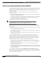
Route Processor Redundant Operation (Catalyst 8540 MSR)
The ATM switch router supports fault tolerance by allowing a secondary route processor to take over if
the primary fails. This secondary, or redundant, route processor runs in standby mode. In standby mode,
the secondary route processor is partially booted with the Cisco IOS software; however, no
configuration is loaded.
At the time of a switchover, the secondary route processor takes over as primary and loads the
configuration as follows:
•
If the running configuration between the primary and secondary route processors match, the new
primary uses the running configuration file
•
If the running configuration between the primary and secondary route processors do not match, the
new primary uses the last saved configuration file in its nonvolatile random-access memory
(NVRAM) (not the NVRAM of the former primary)
The former primary then becomes the secondary route processor.
Note
If the secondary route processor is unavailable, a major alarm is reported. Use the show
facility-alarm status command to display the redundancy alarm status.
When the ATM switch router is powered on, the two route processors go through an arbitration to
determine which is the primary route processor and which is the secondary. The following rules apply
during arbitration:
•
A newly inserted route processor card always comes up as the secondary, except in cases where the
newly inserted card is the only one present.
•
If the configuration is corrupted, one of the route processors comes up as primary, allowing you to
correct the situation manually.
•
The primary route processor when the ATM switch is powered off continues as the primary when
the ATM switch is powered on.
•
If none of the above conditions is true, the route processor in slot 4 becomes the primary.
During normal operation, the primary route processor is booted completely. The secondary CPU is
partially up, meaning it stops short of parsing the configuration. From this point, the primary and
secondary processors communicate periodically to synchronize any system configuration changes.
The following situations can cause a switchover of the primary route processor:
•
The primary route processor is removed or swapped. When a route processor functioning as
primary is removed, the secondary takes over. The ATM switch router is now nonredundant until a
second route processor is inserted.
•
The primary route processor is rebooted. When a route processor functioning as primary is
rebooted, the secondary takes over.
•
The primary route processor fails. The secondary route processor takes over as primary, using the
last saved configuration (or the current running configuration if they have been synchronized with
the sync config command).
•
A switchover is manually forced with the redundancy force-failover main-cpu command.
When a switchover occurs, permanent virtual channels (PVCs) are preserved; switched virtual channels
(SVCs) and Integrated Local Management Interface (ILMI) address states are lost, and then restored
after they are dynamically redetermined.
ATM Switch Router Software Configuration Guide
3-24
78-6277-03, Cisco IOS Release 12.0(13)W5(19)
Chapter 3
Initially Configuring the ATM Switch Router
Configuring Redundancy and Enhanced High System Availability (Catalyst 8540 MSR)
Configuring Route Processor Redundancy (Catalyst 8540 MSR)
For redundant operation, the following requirements must be met:
•
Two route processors and three switch cards are required.
•
The route processors must have identical hardware configurations. This includes variables such as
DRAM size, presence or absence of network clock modules, and so on.
•
Both route processors must have the same functional image. For more information, see the
“Maintaining Functional Images (Catalyst 8540 MSR)” section on page 22-5.
•
Both route processors must be running the same system image.
•
Both route processors must be set to autoboot (a default setting).
If these requirements are met, the ATM switch router runs in redundant mode by default. The tasks
described in the following sections are optional and used only to change nondefault values.
Forcing a Route Processor Switchover (Catalyst 8540 MSR)
You can manually force the secondary route processor to take over as primary. To do so, use the
following privileged EXEC command:
Command
Purpose
redundancy force-failover main-cpu
Forces a route processor switchover.
As long as you have not changed the default configuration register setting, which is set to autoboot
by default, the secondary route processor (formerly the primary) completes the boot process from
standby mode.
If you have changed the default configuration register value, you can change it back to autoboot, and
ensure that the correct system image is used at startup, by performing the following steps, beginning in
global configuration mode:
Command
Purpose
Step 1
Switch(config)# config-register 0x2102
Sets the config register for autoboot.
Step 2
Switch(config)# boot system {[device:]filename Specifies the system image file to load at startup.
[hostname | ip-address] | flash [device:][filename]
| mop filename [type] [card/subcard/port] | rcp
filename [ip-address] | rom | tftp filename
[hostname | ip-address]}
Step 3
Switch(config)# end
Returns to privileged EXEC mode.
Switch#
Step 4
Switch# copy running-config startup-config
Note
If the secondary route processor remains in ROM monitor mode, you can manually boot
the processor from either the bootflash or Flash PC card.
Saves the configuration to NVRAM.
ATM Switch Router Software Configuration Guide
78-6277-03, Cisco IOS Release 12.0(13)W5(19)
3-25
Chapter 3
Initially Configuring the ATM Switch Router
Configuring Redundancy and Enhanced High System Availability (Catalyst 8540 MSR)
Caution
If no system image is specified in the startup configuration, the ROM monitor
automatically boots the first system image on the Flash PC card in slot0. If there is no
system image on the Flash PC card, or the Flash PC card is not available, the ROM monitor
boots the first system image in bootflash. If there is no system image in bootflash, the
switch remains in ROM monitor mode.
Displaying the Configuration Register Value
To display the configuration register value, use the following privileged EXEC command:
Command
Purpose
show version
Displays the configuration register value.
The following example shows the configuration register value:
Switch# show version
Cisco Internetwork Operating System Software
IOS (tm) PNNI Software (cat8540m-WP-M), Version XX.X(X)WX(X),
Copyright (c) 1986-19XX by cisco Systems, Inc.
Compiled Mon XX-XXX-XX 10:15 by integ
Image text-base: 0x60010930, data-base: 0x606CE000
RELEASE SOFTWARE
ROM: System Bootstrap, Version XX.XXX.X(X)WX(X) [BLD-JAGUAR120-4.0.9 ], E
Switch uptime is 3 weeks, 5 days, 23 hours, 30 minutes
System restarted by bus error at PC 0x6007EF24, address 0xFC
System image file is "bootflash:cat8540m-wp-mz.XXX-X.X.WX.X.XX"
cisco C8540MSR (R5000) processor with 65536K/256K bytes of memory.
R5000 processor, Implementation 35, Revision X.X (512KB Level 2 Cache)
Last reset from power-on
1 Ethernet/IEEE 802.3 interface(s)
9 ATM network interface(s)
507K bytes of non-volatile configuration memory.
8192K bytes of Flash PCMCIA card at slot 0 (Sector size 128K).
8192K bytes of Flash internal SIMM (Sector size 256K).
Secondary is up
Secondary has 0K bytes of memory.
Configuration register is 0x100 (will be 0x2102 at next reload)
Synchronizing the Configurations (Catalyst 8540 MSR)
During normal operation, the startup and running configurations are synchronized by default between
the two route processors. In the event of a switchover, the new primary route processor uses the current
configuration. Configurations synchronize either immediately from the command line or during route
processor switchover.
ATM Switch Router Software Configuration Guide
3-26
78-6277-03, Cisco IOS Release 12.0(13)W5(19)
Chapter 3
Initially Configuring the ATM Switch Router
Configuring Redundancy and Enhanced High System Availability (Catalyst 8540 MSR)
Immediately Synchronizing Route Processor Configurations (Catalyst 8540 MSR)
To immediately synchronize the configurations used by the two route processors, use the following
privileged EXEC command on the primary route processor:
Command
Purpose
redundancy manual-sync {startup-config |
running-config | both}
Immediately synchronizes the configuration.
Example
In the following example, both the startup and running configurations are synchronized immediately:
Switch# redundancy manual-sync both
Synchronizing the Configurations During Switchover (Catalyst 8540 MSR)
To manually synchronize the configurations used by the two route processors during a switchover,
perform the following steps on the primary route processor, beginning in global configuration mode:
Step 1
Command
Purpose
Switch(config)# redundancy
Enters redundancy configuration mode.
Switch(config-r)#
Step 2
Switch(config-r)# main-cpu
Enters main-cpu configuration submode.
Switch(config-r-mc)#
Step 3
Switch(config-r-mc)# sync config {startup |
running | both}1
Synchronizes either or both configurations during
switchover or writing the files to NVRAM.
Step 4
Switch(config-r-mc)# end
Returns to privileged EXEC mode.
Switch#
Step 5
Switch# copy running-config startup-config
Forces a manual synchronization of the
configuration files in NVRAM.
Note
1.
This step is unnecessary to synchronize
the running configuration file in DRAM.
Alternatively, you can force an immediate synchronization by entering the redundancy manual-sync command in
privileged EXEC mode.
Example
In the following example, both the startup and running configurations are synchronized:
Switch(config)# redundancy
Switch(config-r)# main-cpu
Switch(config-r-mc)# sync config both
Switch(config-r-mc)# end
Switch# copy running-config startup-config
ATM Switch Router Software Configuration Guide
78-6277-03, Cisco IOS Release 12.0(13)W5(19)
3-27
Chapter 3
Initially Configuring the ATM Switch Router
Configuring Redundancy and Enhanced High System Availability (Catalyst 8540 MSR)
Displaying the Route Processor Redundancy Configuration
(Catalyst 8540 MSR)
To display the route processor redundancy configuration, use the following privileged EXEC command:
Command
Purpose
show redundancy
Displays the redundancy configuration.
In the following example shows the route processor redundancy configuration:
Switch# show redundancy
This CPU is the PRIMARY
Primary
------Slot:
Uptime:
Image:
4
1 day, 18 hours, 40 minutes
PNNI Software (cat8540m-WP-M), Version 12.0(4a)W5(10.44)
Time Since :
Last Running Config. Sync:
Last Startup Config. Sync:
Last Restart Reason:
3 hours, 13 minutes
Never
Normal Boot
Secondary
--------State:
Slot:
Uptime:
Image:
UP
8
3 hours, 16 minutes
PNNI Software (cat8540m-WP-M), Version 12.0(4a)W5(10.46)
Preparing a Route Processor for Removal (Catalyst 8540 MSR)
Before removing a route processor that is running the IOS in secondary mode, it is necessary to change
it to ROM monitor mode. You could use the reload command to force the route processor to ROM
monitor mode but the automatic reboot would occur and you would interrupt switch traffic.
Caution
If you fail to prepare the secondary route processor for removal, the traffic through the
switch could be interrupted.
ATM Switch Router Software Configuration Guide
3-28
78-6277-03, Cisco IOS Release 12.0(13)W5(19)
Chapter 3
Initially Configuring the ATM Switch Router
Configuring Redundancy and Enhanced High System Availability (Catalyst 8540 MSR)
To change the secondary route processor to ROM monitor mode and eliminate the automatic reboot
prior to removal, perform the following task beginning in privileged EXEC mode:
Command
Purpose
Step 1
Switch# copy running-config startup-config
Forces a manual synchronization of the
configuration files in NVRAM.
Step 2
Switch)# redundancy prepare-for-cpu-removal Changes the current route processor to ROM
monitor mode prior to removal.
Example
The following example shows how to change the current route processor to ROM monitor mode prior
to removal:
Switch# copy running-config startup-config
Destination filename [startup-config]?
Building configuration...
EHSA:Syncing monvars to secondary, : BOOT=
EHSA:Syncing monvars to secondary, : CONFIG_FILE=
EHSA:Syncing monvars to secondary, : BOOTLDR=[OK]
Switch#
Switch# redundancy prepare-for-cpu-removal
This command will cause this CPU to go to the
rom monitor through a forced crash.
After this cpu goes to the rom monitor prompt, it is
safe to remove it from the chassis
Please DO NOT REBOOT this cpu before removing it
Do you want to remove it?[confirm]y
Queued messages:
1d22h: %SYS-3-LOGGER_FLUSHING: System pausing to ensure console debugging outpu.
*** System received a reserved exception ***
signal= 0x9, code= 0x0, context= 0x61818df8
PC = 0x600b62e0, Cause = 0x20, Status Reg = 0x34008702
AT: be840000, V0: 9, V1: 0
A0: 2b, A1: 9, A2: 0
A3: 61818df8, T0: 30, T1: 34008701
T2: 34008700, T3: ffff00ff, T4: 61059f88
T5: 7f, T6: 0, T7: 0
S0: 34008701, S1: 1, S2: 9
S3: 0, S4: 61818df8, S5: 611f8540
S6: 611e3740, S7: 61363710, T8: 47d1
T9: 618189d8, K0: 61612634, K1: 600b7e30
GP: 61177fa0, SP: 61818da8, S8: 611e3740
RA: 600a81b8
STATUS: 34008702
mdlo_hi: 0, mdlo: 0
mdhi_hi: 0, mdhi: 0
bvaddr_hi: ffffffff, bvaddr_lo: ffffffff
cause: 20, epc_hi: 0, epc:600b62e0
err_epc_hi: 0, err_epc: 200004
TIGER Masked Interrupt Register = 0x0000007f
TIGER Interrupt Value Register = 0x00000020
monitor: command "boot" @Ø--<ÒagZç
rommon 3 >
ATM Switch Router Software Configuration Guide
78-6277-03, Cisco IOS Release 12.0(13)W5(19)
3-29
Chapter 3
Initially Configuring the ATM Switch Router
Configuring Redundancy and Enhanced High System Availability (Catalyst 8540 MSR)
Configuring Switch Fabric Enhanced High System Availability Operation
(Catalyst 8540 MSR)
Slots 5, 6, and 7 in the ATM switch router chassis can accommodate either two or three switch
processor cards, with a switching capacity of 10 Gbps each. The possible configurations are as follows:
•
Two switch processors—20 Gbps non-EHSA switching fabric (no spare)
•
Three switch processors—20 Gbps EHSA switching fabric (one spare)
When three switch processors are installed, two are active at any time, while the third runs in standby
mode. By default, switch processors 5 and 7 are active and switch processor 6 is the standby. To force
the standby switch processor to become active, use the redundancy preferred-switch-card-slots
command.
Caution
Do not hot swap an active switch processor module before putting it in standby mode.
Removing an active switch processor breaks active connections and stops the flow of
traffic through the switch. Put an active switch in standby mode using the redundancy
preferred-switch-card-slots command before removing it from the chassis.
When a switchover to the standby switch processor occurs, the system resets and all connections are
lost. When the system comes up again, all PVCs and SVCs are reestablished automatically.
Configuring Preferred Switching Processors (Catalyst 8540 MSR)
To configure which two of the three switch processors are active and which runs in standby mode, use
the following privileged EXEC command on the primary route processor:
Command
Purpose
redundancy preferred-switch-card-slots
{5 | 6 | 7} {5 | 6 | 7}
Configures the active and standby switch
processors.
Example
In the following example, the preferred switch processors are configured to be in slots 5 and 7 with the
slot 6 switch processor running in standby mode:
Switch# redundancy preferred-switch-card-slots 5 7
The preferred switch cards selected are already active
Note
The preferred switch card slot configuration reverts to the default configuration when the
switch is power cycled.
ATM Switch Router Software Configuration Guide
3-30
78-6277-03, Cisco IOS Release 12.0(13)W5(19)
Chapter 3
Initially Configuring the ATM Switch Router
Configuring Redundancy and Enhanced High System Availability (Catalyst 8540 MSR)
Displaying the Preferred Switch Processor Redundancy Configuration (Catalyst 8540 MSR)
To display the preferred switch processor redundancy configuration, use the following privileged EXEC
command:
Command
Purpose
show preferred-switch-card-slots
Displays the redundancy configuration.
The following example shows the preferred switch processor redundancy configuration:
Switch# show preferred-switch-card-slots
The currently preferred switch card slots are slot: 5 and slot: 7
The currently active switch card slots are slot: 5 and slot: 7
Displaying the Switch Processor EHSA Configuration (Catalyst 8540 MSR)
To display the switch processor EHSA configuration, use the following privileged EXEC command:
Command
Purpose
show capability {primary | secondary}
Displays the switch redundancy
configuration.
The following shows the primary switch processor EHSA configuration:
Switch# show capability primary
Dram Size is :64 MB
Pmem Size is :4 MB
Nvram Size is :512 KB
BootFlash Size is :8 MB
ACPM hw version 5.2
ACPM functional version 4.0
Netclk Module present flag :16
NCLK hw version 3.1
NCLK func version 8.0
Printing the parameters for Switch card: 0
SWC0 HW version 7.2
SWC0 Functional version 1.2
SWC0 Table memory size: 0 MB
SWC0 Feat Card Present Flag: 0
SWC0 Feat Card HW version 0.0
SWC0 Feat Card Functional version 0.0
Printing the parameters for Switch card: 1
SWC1 HW version 0.0
SWC1 Functional version 0.0
SWC1 Table memory size: 0 MB
SWC1 Feat Card Present Flag: 0
SWC1 Feat Card HW version 0.0
SWC1 Feat Card Functional version 0.0
Printing the parameters for Switch card: 2
SWC2 HW version 7.2
SWC2 Functional version 1.2
SWC2 Table memory size: 0 MB
ATM Switch Router Software Configuration Guide
78-6277-03, Cisco IOS Release 12.0(13)W5(19)
3-31
Chapter 3
Initially Configuring the ATM Switch Router
Configuring SNMP and RMON
SWC2 Feat Card Present Flag: 0
SWC2 Feat Card HW version 0.0
SWC2 Feat Card Functional version 0.0
Number of Controller supported in IOS: 7
Driver 0 type: 2560 super cam Functional Version 1.3
Driver 1 type: 2562 OC12 SPAM Functional Version 5.1
Driver 2 type: 2564 OC mother board Functional Version 5.1
Driver 3 type: 258 Switch Card Functional Version 1.0
Driver 4 type: 259 Switch Feature Card Functional Version 4.0
Configuring SNMP and RMON
SNMP is an application-layer protocol that allows an SNMP manager, such a network management
system (NMS), and an SNMP agent on the managed device to communicate. You can configure
SNMPv1, SNMPv2, or both, on the ATM switch router. Remote Monitoring (RMON) allows you to see
the activity on network nodes. By using RMON in conjunction with the SNMP agent on the ATM switch
router, you can monitor traffic through network devices, segment traffic that is not destined for the
ATM switch router, and create alarms and events for proactive traffic management.
For detailed instructions on SNMP and general RMON configuration, refer to the Configuration
Fundamentals Configuration Guide. For instructions on configuring ATM RMON, refer to Chapter 14,
“Configuring ATM Accounting and ATM RMON.”
Storing the Configuration
When autoconfiguration and any manual configurations are complete, you should copy the
configuration into nonvolatile random-access memory (NVRAM). If you should power off your
ATM switch router prior to saving the configuration in NVRAM, all manual configuration changes
are lost.
To save the running configuration to NVRAM, use the following command in privileged EXEC mode:
Command
Purpose
copy system:running-config
nvram:startup-config
Copies the running configuration in system
memory to the startup configuration stored in
NVRAM.
Testing the Configuration
The following sections describe tasks you can perform to confirm the hardware, software, and interface
configuration:
•
Confirming the Hardware Configuration (Catalyst 8540 MSR) on page 3-33
•
Confirming the Hardware Configuration (Catalyst 8510 MSR and LightStream 1010) on page 3-34
ATM Switch Router Software Configuration Guide
3-32
78-6277-03, Cisco IOS Release 12.0(13)W5(19)
Chapter 3
Initially Configuring the ATM Switch Router
Testing the Configuration
•
Confirming the Software Version on page 3-34
•
Confirming Power-on Diagnostics (Catalyst 8540 MSR) on page 3-35
•
Confirming the Ethernet Configuration on page 3-36
•
Confirming the ATM Address on page 3-37
•
Testing the Ethernet Connection on page 3-37
•
Confirming the ATM Connections on page 3-38
•
Confirming the ATM Interface Configuration on page 3-38
•
Confirming the Interface Status on page 3-39
•
Confirming Virtual Channel Connections on page 3-39
•
Confirming the Running Configuration on page 3-41
•
Confirming the Saved Configuration on page 3-42
Note
The following examples differ depending on whether the switch processor feature card is
present. (Catalyst 8540 MSR)
Note
The following examples differ depending on the feature card installed on the processor.
(Catalyst 8510 MSR and LightStream 1010)
Confirming the Hardware Configuration (Catalyst 8540 MSR)
Use the show hardware and show capability commands to confirm the correct hardware installation:
Switch# show hardware
C8540 named Switch, Date: 08:36:44 UTC Fri May 21 1999
Slot
---0/*
0/0
0/1
4/*
4/0
5/*
5/0
7/*
7/0
8/*
8/0
Ctrlr-Type
-----------Super Cam
155MM PAM
155MM PAM
Route Proc
Netclk Modul
Switch Card
Feature Card
Switch Card
Feature Card
Route Proc
Netclk Modul
Part No. Rev
---------- -73-2739-02 02
73-1496-03 06
73-1496-03 00
73-2644-05 A0
73-2868-03 A0
73-3315-08 B0
73-3408-04 B0
73-3315-08 B0
73-3408-04 B0
73-2644-05 A0
73-2868-03 A0
Ser No
-------07287xxx
02180424
02180455
03140NXK
03140NSU
03170SMB
03160S4H
03160SDT
03160RQV
03140NXH
03140NVT
DS1201 Backplane EEPROM:
Model Ver. Serial MAC-Address MAC-Size
------ ---- -------- ------------ -------C8540 2
6315484 00902156D800
1024
cubi version : F
Mfg Date
--------Mar 31 98
Jan 16 96
Jan 17 96
Apr 04 99
Apr 04 99
May 03 99
May 03 99
May 03 99
May 03 99
Apr 04 99
Apr 04 99
RMA
--0
RMA No. Hw Vrs Tst EEP
-------- ------- --- --3.0
00-00-00
3.0
0
2
00-00-00
3.0
0
2
0
5.7
0
3.1
0
8.3
0
4.1
0
8.3
0
4.1
0
5.7
0
3.1
RMA-Number
MFG-Date
---------- ----------0
Mar 23 1999
Power Supply:
Slot Part No.
Rev Serial No. RMA No.
Hw Vrs Power Consumption
---- ---------------- ---- ----------- ----------- ------- ----------------0
34-0829-02 A000 APQ0225000R 00-00-00-00
1.0
2746 cA
ATM Switch Router Software Configuration Guide
78-6277-03, Cisco IOS Release 12.0(13)W5(19)
3-33
Chapter 3
Initially Configuring the ATM Switch Router
Testing the Configuration
See the “Displaying the Switch Processor EHSA Configuration (Catalyst 8540 MSR)” section on
page 3-31 for an example of the show capability command.
Confirming the Hardware Configuration (Catalyst 8510 MSR and
LightStream 1010)
Use the show hardware command to confirm the correct hardware installation:
Switch# show hardware
LS1010 named ls1010_c5500, Date: XX:XX:XX UTC Thu Jan 8 1998
Feature Card's FPGA Download Version: 10
Slot
---0/0
0/1
1/0
1/1
3/0
2/0
2/1
Ctrlr-Type
-----------T1 PAM
T1 PAM
155MM PAM
QUAD DS3 PAM
155MM PAM
ATM Swi/Proc
FeatureCard1
Part No. Rev
---------- -12-3456-78 00
12-3456-78 00
73-1496-03 06
73-2197-02 00
73-1496-03 00
73-1402-06 D0
73-1405-05 B0
Ser No
-------00000022
00000025
02180446
03656116
02180455
07202996
07202788
DS1201 Backplane EEPROM:
Model Ver. Serial MAC-Address MAC-Size
------ ---- -------- ------------ -------LS1010 2
69000050 00400B0A2E80
256
Mfg Date
--------Aug 01 95
Aug 01 95
Jan 17 96
Dec 18 96
Jan 17 96
Dec 20 97
Dec 20 97
RMA
--0
RMA No. Hw Vrs Tst EEP
-------- ------- --- --00-00-00
0.4
0
2
00-00-00
0.4
0
2
00-00-00
3.0
0
2
00-00-00
1.0
0
2
00-00-00
3.0
0
2
00-00-00
4.1
0
2
00-00-00
3.2
0
2
RMA-Number
---------0
MFG-Date
----------Aug 01 1995
Confirming the Software Version
Use the show version command to confirm the correct version and type of software and the
configuration register are installed:
Switch# show version
Cisco Internetwork Operating System Software
IOS (tm) PNNI Software (cat8540m-WP-M), Version XX.X(X), RELEASE SOFTWARE
Copyright (c) 1986-1998 by cisco Systems, Inc.
Compiled XXX XX-XXX-XX XX:XX by
Image text-base: 0x600108B4, data-base: 0x6057A000
ROM: System Bootstrap, Version XX.X(X) RELEASE SOFTWARE
Switch uptime is 1 hour, 1 minute
System restarted by reload
System image file is "tftp://cat8540m-wp-mz_nimmu"
cisco C8540MSR (R5000) processor with 65536K/256K bytes of memory.
R5000 processor, Implementation 35, Revision 2.1 (512KB Level 2 Cache)
Last reset from power-on
1 Ethernet/IEEE 802.3 interface(s)
8 ATM network interface(s)
507K bytes of non-volatile configuration memory.
16384K bytes of Flash PCMCIA card at slot 0 (Sector size 128K).
8192K bytes of Flash internal SIMM (Sector size 256K).
Configuration register is 0x0
ATM Switch Router Software Configuration Guide
3-34
78-6277-03, Cisco IOS Release 12.0(13)W5(19)
Chapter 3
Initially Configuring the ATM Switch Router
Testing the Configuration
Confirming Power-on Diagnostics (Catalyst 8540 MSR)
Use the show diag power-on command to confirm the power-on diagnostics:
Switch# show diag power-on
Cat8540 Power-on Diagnostics Status (.=Pass,F=Fail,U=Unknown,N=Not Applicable)
----------------------------------------------------------------------------Last Power-on Date: 1999/07/28
Time: 11:06:12
BOOTFLASH: .
CPU-IDPROM: .
ETHSRAM:
.
PCMCIA-Slot0: .
NVRAM-Config: .
DRAM:
.
PCMCIA-Slot1: .
PS0:
FAN:
PS2:
Temperature:
PS (12V):
Bkp-IDPROM:
.
.
SARSRAM:
N
.
Ethernet-port Access:
.
Ethernet-port Loopback: .
.
.
.
Ethernet-port CAM-Access: .
Ethernet-port Loadgen:
.
Power-on Diagnostics Passed.
Confirming Power-on Diagnostics (Catalyst 8510 MSR and LightStream 1010)
Use the show diag power-on command to confirm the power-on diagnostics:
NewLs1010# show diag power-on
LS1010 Power-on Diagnostics Status (.=Pass,F=Fail,U=Unknown,N=Not Applicable)
----------------------------------------------------------------------------Last Power-on Diags Date: 99/07/09
Time: 07:52:17
By: V 4.51
BOOTFLASH: .
CPU-IDPROM: .
SRAM:
.
PCMCIA-Slot0: .
FCard-IDPROM: .
DRAM:
.
PCMCIA-Slot1: N
NVRAM-Config: .
PS1:
FAN:
PS2:
Temperature:
PS (12V):
Bkp-IDPROM:
.
.
MMC-Switch Access: .
LUT: .
ITT: .
OPT: .
Cell-Memory: .
FC-PFQ
Access: .
RST: .
TEST:
CELL: .
TGRP: .
REG: .
SNAKE: .
UPC : .
N
.
Accordian Access: .
STK: .
LNK: .
ATTR: .
OTT: .
IVC: .
RATE: .
ABR : .
.
.
IFILL: .
OVC: .
MCAST: .
RSTQ : .
Queue: .
OFILL: .
SCHED: .
ATM Switch Router Software Configuration Guide
78-6277-03, Cisco IOS Release 12.0(13)W5(19)
3-35
Chapter 3
Initially Configuring the ATM Switch Router
Testing the Configuration
Access/Interrupt/Loopback/CPU-MCast/Port-MCast/FC-MCast/FC-TMCC Test Status:
Ports
0
1
2
3
---------------------------------------------------------------------------PAM 0/0 (IMA8T1)
.....NN
.....NN
.....NN
.....NN
Port 4 to 7 :
.....NN
.....NN
.....NN
.....NN
PAM 0/1 (IMA8E1)
.....NN
.....NN
.....NN
.....NN
Port 4 to 7 :
.....NN
.....NN
.....NN
.....NN
PAM 1/0 (FR4CE1)
.....NN
.....NN
.....NN
.....NN
PAM 1/1 (155UTP)
.....NN
.....NN
.....NN
.....NN
PAM 3/0 (T1)
.....NN
.....NN
.....NN
.....NN
PAM 3/1 (E1CEUTP)
.....NN
.....NN
.....NN
.....NN
PAM 4/0 (DS3)
.....NN
.....NN
N
N
PAM 4/1 (25M)
.....NN
.....NN
.....NN
.....NN
Port 4 to 7 :
.....NN
.....NN
.....NN
.....NN
Port 8 to 11:
.....NN
.....NN
.....NN
.....NN
FRPAM#
ING-SSRAM ING-SDRAM EGR-SSRAM EGR-SDRAM LOOPBACK
-----------------------------------------------------------------PAM 1/0 (FR4CE1) .
.
.
.
.
Ethernet-port Access:
.
Ethernet-port CAM-Access: .
Ethernet-port Loopback: .
Ethernet-port Loadgen:
.
GEPAM Microcode:
.
GEPAM Access:
.
GEPAM CAM Access:
.
Power-on Diagnostics Passed.
Confirming the Ethernet Configuration
Use the show interfaces command to confirm that the Ethernet interface on the route processor is
configured correctly:
Switch# show interfaces ethernet 0
Ethernet0 is up, line protocol is up
Hardware is SonicT, address is 0000.0000.0000 (bia 0000.0000.0000)
Internet address is 172.20.52.20/26
MTU 1500 bytes, BW 10000 Kbit, DLY 1000 usec, rely 255/255, load 1/255
Encapsulation ARPA, loopback not set, keepalive set (10 sec)
ARP type: ARPA, ARP Timeout 04:00:00
Last input 00:00:00, output 00:00:00, output hang never
Last clearing of "show interface" counters never
Queueing strategy: fifo
Output queue 0/40, 0 drops; input queue 0/75, 0 drops
5 minute input rate 1000 bits/sec, 2 packets/sec
5 minute output rate 0 bits/sec, 1 packets/sec
69435 packets input, 4256035 bytes, 0 no buffer
Received 43798 broadcasts, 0 runts, 0 giants, 0 throttles
0 input errors, 0 CRC, 0 frame, 0 overrun, 0 ignored, 0 abort
0 input packets with dribble condition detected
203273 packets output, 24079764 bytes, 0 underruns
0 output errors, 0 collisions, 2 interface resets
0 babbles, 0 late collision, 0 deferred
0 lost carrier, 0 no carrier
0 output buffer failures, 0 output buffers swapped out
ATM Switch Router Software Configuration Guide
3-36
78-6277-03, Cisco IOS Release 12.0(13)W5(19)
Chapter 3
Initially Configuring the ATM Switch Router
Testing the Configuration
Confirming the ATM Address
Use the show atm addresses command to confirm correct configuration of the ATM address for the
ATM switch router:
Switch# show atm addresses
Switch Address(es):
47.009181000000000100000001.000100000001.00 active
Soft VC Address(es):
47.0091.8100.0000.0001.0000.0001.4000.0c80.9000.00
47.0091.8100.0000.0001.0000.0001.4000.0c80.9010.00
47.0091.8100.0000.0001.0000.0001.4000.0c80.9020.00
47.0091.8100.0000.0001.0000.0001.4000.0c80.9030.00
47.0091.8100.0000.0001.0000.0001.4000.0c81.8000.00
47.0091.8100.0000.0001.0000.0001.4000.0c81.8000.63
47.0091.8100.0000.0001.0000.0001.4000.0c81.8010.00
47.0091.8100.0000.0001.0000.0001.4000.0c81.8020.00
47.0091.8100.0000.0001.0000.0001.4000.0c81.8030.00
47.0091.8100.0000.0001.0000.0001.4000.0c81.9000.00
47.0091.8100.0000.0001.0000.0001.4000.0c81.9010.00
47.0091.8100.0000.0001.0000.0001.4000.0c81.9020.00
47.0091.8100.0000.0001.0000.0001.4000.0c81.9030.00
ATM1/1/0
ATM1/1/1
ATM1/1/2
ATM1/1/3
ATM3/0/0
ATM3/0/0.99
ATM3/0/1
ATM3/0/2
ATM3/0/3
ATM3/1/0
ATM3/1/1
ATM3/1/2
ATM3/1/3
<information deleted>
ILMI Switch Prefix(es):
47.0091.8100.0000.0001.0000.0001
ILMI Configured Interface Prefix(es):
LECS Address(es):
Testing the Ethernet Connection
After you have configured the IP address(es) for the Ethernet interface, test for connectivity between the
switch and a host. The host can reside anywhere in your network. To test for Ethernet connectivity, use
the following user EXEC command:
Command
Purpose
ping ip ip-address
Tests the configuration using the ping
command. The ping command sends an echo
request to the host specified in the command .
For example, to test Ethernet connectivity from the switch to a workstation with an IP address of
172.20.40.201, enter the command ping ip 172.20.40.201. If the switch receives a response, the
following message displays:
Switch# ping ip 172.20.40.201
Type escape sequence to abort.
Sending 5, 100-byte ICMP Echos to 172.20.40.201, timeout is 2 seconds:
!!!!!
Success rate is 100 percent (5/5), round-trip min/avg/max = 1/202/1000 ms
ATM Switch Router Software Configuration Guide
78-6277-03, Cisco IOS Release 12.0(13)W5(19)
3-37
Chapter 3
Initially Configuring the ATM Switch Router
Testing the Configuration
Confirming the ATM Connections
Use the ping atm interface command to confirm that the ATM connections are configured correctly:
Switch# ping atm interface atm 3/0/0 0 5 seg-loopback
Type escape sequence to abort.
Sending Seg-Loopback 5, 53-byte OAM Echoes to a neighbour,timeout is 5 seconds:
!!!!!
Success rate is 100 percent (5/5), round-trip min/avg/max = 1/1/4 ms
Switch#
Confirming the ATM Interface Configuration
Use the show atm interface command to confirm the ATM interfaces are configured correctly:
Switch# show atm interface atm 1/0/0
Interface:
ATM1/0/0
Port-type:
oc3suni
IF Status:
UP
Admin Status:
up
Auto-config:
disabled
AutoCfgState:
not applicable
IF-Side:
Network
IF-type:
NNI
Uni-type:
not applicable Uni-version:
not applicable
Max-VPI-bits:
8
Max-VCI-bits:
14
Max-VP:
255
Max-VC:
16383
ConfMaxSvpcVpi: 255
CurrMaxSvpcVpi: 255
ConfMaxSvccVpi: 255
CurrMaxSvccVpi: 255
ConfMinSvccVci: 35
CurrMinSvccVci: 35
Svc Upc Intent: pass
Signalling:
Enabled
ATM Address for Soft VC: 47.0091.8100.0000.00e0.4fac.b401.4000.0c80.8000.00
Configured virtual links:
PVCLs SoftVCLs
SVCLs
TVCLs
PVPLs SoftVPLs
SVPLs Total-Cfgd Inst-Conns
4
0
0
0
1
0
0
5
3
Logical ports(VP-tunnels):
1
Input cells:
263109
Output cells:
268993
5 minute input rate:
0 bits/sec,
0 cells/sec
5 minute output rate:
1000 bits/sec,
2 cells/sec
Input AAL5 pkts: 171788, Output AAL5 pkts: 174718, AAL5 crc errors: 0
ATM Switch Router Software Configuration Guide
3-38
78-6277-03, Cisco IOS Release 12.0(13)W5(19)
Chapter 3
Initially Configuring the ATM Switch Router
Testing the Configuration
Confirming the Interface Status
Use the show atm status command to confirm the status of ATM interfaces:
Switch# show atm status
NUMBER OF INSTALLED CONNECTIONS: (P2P=Point to Point, P2MP=Point to MultiPoint)
Type
P2P
P2MP
PVCs
30
0
SoftPVCs
0
0
SVCs
0
0
PVPs SoftPVPs
SVPs
1
1
0
1
0
0
TOTAL INSTALLED CONNECTIONS =
Total
32
1
33
PER-INTERFACE STATUS SUMMARY AT 16:07:59 UTC Wed Nov 5 1997:
Interface
IF
Admin Auto-Cfg
ILMI Addr
SSCOP
Hello
Name
Status
Status
Status
Reg State
State
State
------------- -------- ------------ -------- ------------ --------- -------ATM1/1/0
DOWN
down waiting
n/a
Idle
n/a
ATM1/1/1
DOWN
down waiting
n/a
Idle
n/a
ATM1/1/2
DOWN
down waiting
n/a
Idle
n/a
ATM1/1/3
DOWN
down waiting
n/a
Idle
n/a
ATM0
UP
up
n/a UpAndNormal
Idle
n/a
ATM3/0/0
UP
up
n/a UpAndNormal
Active LoopErr
ATM3/0/0.99
UP
up waiting WaitDevType
Idle
n/a
ATM3/0/1
UP
up
done UpAndNormal
Active LoopErr
ATM3/0/2
UP
up
n/a UpAndNormal
Active LoopErr
ATM3/0/3
UP
up
done UpAndNormal
Active LoopErr
ATM3/1/0
UP
up
done UpAndNormal
Active LoopErr
ATM3/1/1
UP
up
done UpAndNormal
Active LoopErr
ATM3/1/2
UP
up
done UpAndNormal
Active LoopErr
ATM3/1/3
UP
up
done UpAndNormal
Active LoopErr
<information deleted>
Confirming Virtual Channel Connections
Use the show atm vc command to confirm the status of ATM virtual channels:
Switch# show
Interface
ATM1/1/0
ATM1/1/0
ATM1/1/1
ATM1/1/1
ATM1/1/2
ATM1/1/2
ATM1/1/3
ATM1/1/3
ATM0
ATM0
ATM0
ATM0
ATM0
ATM0
ATM0
ATM0
ATM0
ATM0
ATM0
ATM0
<information
atm vc
VPI
VCI
0
5
0
16
0
5
0
16
0
5
0
16
0
5
0
16
0
32
0
33
0
34
0
35
0
36
0
37
0
38
0
39
0
40
0
41
0
42
0
43
deleted>
Type
PVC
PVC
PVC
PVC
PVC
PVC
PVC
PVC
PVC
PVC
PVC
PVC
PVC
PVC
PVC
PVC
PVC
PVC
PVC
PVC
X-Interface
ATM0
ATM0
ATM0
ATM0
ATM0
ATM0
ATM0
ATM0
ATM1/1/0
ATM1/1/1
ATM1/1/2
ATM1/1/3
ATM3/0/0
ATM3/0/1
ATM3/0/2
ATM3/0/3
ATM3/1/0
ATM3/1/1
ATM3/1/2
ATM3/1/3
X-VPI X-VCI
0
52
0
32
0
53
0
33
0
54
0
34
0
55
0
35
0
16
0
16
0
16
0
16
0
16
0
16
0
16
0
16
0
16
0
16
0
16
0
16
Encap Status
QSAAL DOWN
ILMI
DOWN
QSAAL DOWN
ILMI
DOWN
QSAAL DOWN
ILMI
DOWN
QSAAL DOWN
ILMI
DOWN
ILMI
DOWN
ILMI
DOWN
ILMI
DOWN
ILMI
DOWN
ILMI
UP
ILMI
UP
ILMI
UP
ILMI
UP
ILMI
UP
ILMI
UP
ILMI
UP
ILMI
UP
ATM Switch Router Software Configuration Guide
78-6277-03, Cisco IOS Release 12.0(13)W5(19)
3-39
Chapter 3
Initially Configuring the ATM Switch Router
Testing the Configuration
Use the show atm vc interface card/subcard/port command to confirm the status of ATM virtual
channels on a specific interface:
Switch# show
Interface
ATM3/0/0
ATM3/0/0
ATM3/0/0
ATM3/0/0
ATM3/0/0
atm vc
VPI
0
0
0
50
100
interface atm
VCI
Type
5
PVC
16
PVC
18
PVC
100
PVC
200
3/0/0
X-Interface X-VPI X-VCI
ATM0
0
56
ATM0
0
36
ATM0
0
85
ATM3/0/1
60
200
ATM3/0/2
70
210
ATM3/0/3
80
220
SoftVC NOT CONNECTED
Encap Status
QSAAL UP
ILMI
UP
PNNI
UP
DOWN
UP
UP
Use the show atm vc interface atm card/subcard/port vpi vci command to confirm the status of a specific
ATM interface and virtual channel.
Switch# show atm vc interface atm 0/0/0 0 16
Interface: ATM0/0/0, Type: oc3suni
VPI = 0 VCI = 16
Status: DOWN
Time-since-last-status-change: 1w5d
Connection-type: PVC
Cast-type: point-to-point
Packet-discard-option: enabled
Usage-Parameter-Control (UPC): pass
Wrr weight: 15
Number of OAM-configured connections: 0
OAM-configuration: disabled
OAM-states: Not-applicable
Cross-connect-interface: ATM0, Type: Unknown
Cross-connect-VPI = 0
Cross-connect-VCI = 35
Cross-connect-UPC: pass
Cross-connect OAM-configuration: disabled
Cross-connect OAM-state: Not-applicable
Encapsulation: AAL5ILMI
Threshold Group: 6, Cells queued: 0
Rx cells: 0, Tx cells: 0
Tx Clp0:0, Tx Clp1: 0
Rx Clp0:0, Rx Clp1: 0
Rx Upc Violations:0, Rx cell drops:0
Rx pkts:0, Rx pkt drops:0
Rx connection-traffic-table-index: 3
Rx service-category: VBR-RT (Realtime Variable Bit Rate)
Rx pcr-clp01: 424
Rx scr-clp01: 424
Rx mcr-clp01: none
Rx
cdvt: 1024 (from default for interface)
Rx
mbs: 50
Tx connection-traffic-table-index: 3
Tx service-category: VBR-RT (Realtime Variable Bit Rate)
Tx pcr-clp01: 424
Tx scr-clp01: 424
Tx mcr-clp01: none
Tx
cdvt: none
Tx
mbs: 50
ATM Switch Router Software Configuration Guide
3-40
78-6277-03, Cisco IOS Release 12.0(13)W5(19)
Chapter 3
Initially Configuring the ATM Switch Router
Testing the Configuration
Confirming the Running Configuration
Use the more system:running-config command to confirm that the current configuration is correct:
Switch# more system:running-config
version XX.X
no service pad
no service password-encryption
!
hostname Switch
!
<information deleted>
!
interface Ethernet0
ip address 172.20.52.11 255.255.255.224
no ip directed-broadcast
!
interface ATM-E0
no ip address
no ip directed-broadcast
atm pvc 0 29 pd on wrr-weight 15 rx-cttr 3 tx-cttr 3
wrr-weight 15 encap
!
interface Async1
no ip address
no ip directed-broadcast
hold-queue 10 in
!
logging buffered 4096 debugging
!
line con 0
exec-timeout 0 0
transport input none
line vty 0 4
exec-timeout 0 0
no login
!
end
interface
ATM0 0 any-vci
ATM Switch Router Software Configuration Guide
78-6277-03, Cisco IOS Release 12.0(13)W5(19)
3-41
Chapter 3
Initially Configuring the ATM Switch Router
Testing the Configuration
Confirming the Saved Configuration
Use the more nvram:startup-config command to confirm that the configuration saved in NVRAM
is correct:
Switch# more nvram:startup-config
version XX.X
no service pad
no service password-encryption
!
hostname Switch
!
<information deleted>
!
interface Ethernet0
ip address 172.20.52.11 255.255.255.224
no ip directed-broadcast
!
interface ATM-E0
no ip address
no ip directed-broadcast
!
interface Async1
no ip address
no ip directed-broadcast
hold-queue 10 in
!
logging buffered 4096 debugging
!
line con 0
exec-timeout 0 0
transport input none
line vty 0 4
exec-timeout 0 0
no login
!
end
ATM Switch Router Software Configuration Guide
3-42
78-6277-03, Cisco IOS Release 12.0(13)W5(19)