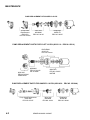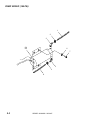
1
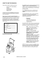
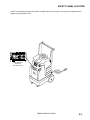
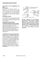
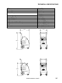
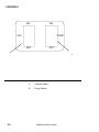
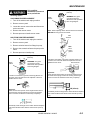
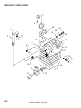
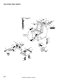
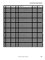
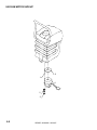
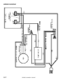
PORTABLE EXTRACTOR
Operating Instructions
MODELS:
406-135MO
10070260
406-131MO
10070240
Read these instructions before using the machine
N
86038580 02/08/07
PRV NO. 98832
MACHINE DATA LOG/OVERVIEW
MODEL _______________________________________
DATE OF PURCHASE __________________________
SERIAL NUMBER ______________________________
SALES REPRESENTATIVE # _____________________
DEALER NAME ________________________________
OPERATIONS GUIDE NUMBER ___________________
PUBLISHED __________________________________________
YOUR DEALER
Name: __________________________________________________________________________________________________
Address: _______________________________________________________________________________________________
For the name and address of your dealer contact: Windsor Industries
Phone Number: _________________________________________________________________________________________
OVERVIEW
The Sensei is an electric powered carpet extractor intended for commercial use. This
appliance applies a cleaning solution to the carpet and then vacuums the soiled water back
into the recovery tank.
2
SENSEI 86038580 02/08/07
TABLE OF CONTENTS
Machine Data Log/Overview.........................1
Table of Contents..........................................2
HOW TO USE THIS MANUAL
How to use this Manual.................................1-1
SAFETY
Important Safety Instructions ........................2-1
Hazard Intensity Level. .................................2-2
Safety Label Location. ..................................2-3
Grounding Instructions..................................2-4
GROUP PARTS LIST
Pump Group (50 psi) .................................. 5-1
Pump Group (100 psi) ................................ 5-3
Recovery Tank Group................................. 5-5
Solution Tank Group .................................. 5-7
Vacuum Motor Group ................................. 5-9
Wiring Group............................................... 5-11
Suggested Spare Parts............................... 5-12
Warranty ..................................................... 5-13
OPERATIONS
Technical Specifications. ..............................3-1
Controls.........................................................3-2
Machine Operation........................................3-3
Pre-Run Machine Inspection......................3-3
Equipment Set-up. .....................................3-3
Emptying & Cleaning Tanks.......................3-3
MAINTENANCE
Daily Maintenance ........................................4-1
Periodic Maintenance ...................................4-1
Monthly Maintenance....................................4-1
Semi-annually ...............................................4-1
Lubrication ....................................................4-1
Storage .........................................................4-1
Vacuum Motor Replacement ........................4-2
Solution Pump Replacement ........................4-2
Pump Replacement Kit .................................4-3
Machine Troubleshooting..............................4-4
SENSEI 86038580 02/08/07
3
HOW TO USE THIS MANUAL
This manual contains the following sections:
-
-
HOW TO USE THIS MANUAL
SAFETY
OPERATIONS
MAINTENANCE
PARTS LIST
The HOW TO USE THIS MANUAL section will tell
you how to find important information for ordering
correct repair parts.
Parts may be ordered from authorized dealers.
When placing an order for parts, the machine model
and machine serial number are important. Refer to
the MACHINE DATA box which is filled out during
the installation of your machine. The MACHINE
DATA box is located on the inside of the front cover
of this manual.
The SAFETY section contains important information
regarding hazard or unsafe practices of the
machine. Levels of hazards are identified that could
result in product or personal injury, or severe injury
resulting in death.
The OPERATIONS section is to familiarize the
operator with the operation and function of the
machine.
The MAINTENANCE section contains preventive
maintenance to keep the machine and its
components in good working condition. They are
listed in this general order:
-
Maintenance
Lubrication
Vacuum Motor Replacement
Solution Pump Replacement
Troubleshooting
The PARTS LIST section contains assembled parts
illustrations and corresponding parts list. The parts
lists include a number of columns of information:
MODEL _____________________________________
DATE OF PURCHASE ________________________
SERIAL NUMBER ____________________________
SALES REPRESENTATIVE # ___________________
-
DEALER NAME ______________________________
OPERATIONS GUIDE NUMBER __________________
-
PUBLISHED ________________________________
-
The model and serial number of your machine is on
the front of the Access Panel.
-
-
REF – column refers to the reference
number on the parts illustration.
PART NO. – column lists the part
number for the part.
PRV NO. – reference number.
QTY – column lists the quantity of the
part used in that area of the machine.
DESCRIPTION – column is a brief
description of the part.
SERIAL NO. FROM – column indicates
the first machine the part number is
applicable to. When the machine design
has changed, this column will indicate
serial number of applicable machine.
The main illustration shows the most
current design of the machine. The
boxed illustrations show older designs.
NOTES – column for information not
noted by the other columns.
NOTE: If a service or option kit is installed on your
machine, be sure to keep the KIT INSTRUCTIONS
which came with the kit. It contains replacement
parts numbers needed for ordering future parts.
1-1
SENSEI 86038580 02/08/07
SAFETY INSTRUCTIONS
IMPORTANT SAFETY INSTRUCTIONS
When using an electrical appliance, basic precaution
must always be followed, including the following:
READ ALL INSTRUCTIONS BEFORE USING THIS MACHINE.
This machine is for commercial use.
! WARNING:
To reduce the risk of fire, electric shock, or injury:
Connect to a properly grounded outlet. See Grounding Instructions.
Do not leave the machine unattended. Unplug machine from outlet when not in use and before
maintenance or service.
Use only indoors. Do not use outdoors or expose to rain.
Do not allow machine to be used as a toy. Close attention is necessary when used by or near
children.
Use only as described in this manual. Use only manufacturer’s recommended components and
attachments.
Do not use damaged electrical cord or plug. Follow all instructions in this manual concerning grounding
the machine. If the machine is not working properly, has been dropped, damaged, left outdoors, or
dropped into water, return it to an authorized service center.
Do not pull or carry machine by electrical cord, use as a handle, close a door on cord, or pull cord
around sharp edges or corners.
Do not run machine over cord. Keep cord away from heated surfaces.
Do not unplug machine by pulling on cord. To unplug, grasp the electrical plug, not the electrical cord.
Do not handle the electrical plug or machine with wet hands.
Do not operate the machine with any openings blocked. Keep openings free of debris that may reduce
airflow.
This machine is intended for cleaning carpet only.
Do not vacuum anything that is burning or smoking, such as cigarettes, matches, or hot ashes.
This machine is not suitable for picking up health endangering dust.
Turn off all controls before unplugging.
Machine can cause a fire when operating near flammable vapors or materials. Do not operate this
machine near flammable fluids, dust or vapors.
This machine is suitable for commercial use, for example in hotels, schools, hospitals,
factories, shops and offices for more than normal housekeeping purposes.
Maintenance and repairs must be done by qualified personnel.
If foam or liquid comes out of machine, switch off immediately.
SAVE THESE INSTRUCTIONS
SENSEI 86038580 02/08/07
2-1
HAZARD INTENSITY LEVEL
The following symbols are used throughout this guide as indicated in their descriptions:
HAZARD INTENSITY LEVEL
There are three levels of hazard intensity identified by signal words -WARNING and CAUTION and FOR
SAFETY. The level of hazard intensity is determined by the following definitions:
! WARNING
WARNING - Hazards or unsafe practices which COULD result in severe personal injury or death.
! CAUTION
CAUTION - Hazards or unsafe practices which could result in minor personal injury or product or property
damage.
FOR SAFETY: To Identify actions which must be followed for safe operation of equipment.
Report machine damage or faulty operation immediately. Do not use the machine if it is not in proper
operating condition. Following is information that signals some potentially dangerous conditions to the
operator or the equipment. Read this information carefully. Know when these conditions can exist. Locate
all safety devices on the machine. Please take the necessary steps to train the machine operating
personnel.
FOR SAFETY:
DO NOT OPERATE MACHINE:
Unless Trained and Authorized.
Unless Operation Guide is Read and understood.
In Flammable or Explosive areas.
In areas with possible falling objects.
WHEN SERVICING MACHINE:
Avoid moving parts. Do not wear loose clothing; jackets, shirts, or sleeves when working on the
machine.
.
2-2
SENSEI 86038580 02/08/07
SAFETY LABEL LOCATION
NOTE: These drawings indicate the location of safety labels on the machine. If at any time the labels become
illegible, promptly replace them.
LABEL WARNING
86242230
PRV NO. 500009
SENSEI 86038580 02/08/07
2-3
GROUNDING INSTRUCTIONS
THIS PRODUCT IS FOR COMMERCIAL USE
ONLY.
ELECTRICAL:
In the USA
this machine operates on a
standard 15 amp 115V, 60 hz, A.C. power
circuit . The amp, hertz, and voltage are listed
on the data label found on each machine.
Using voltages above or below those indicated
on the data label will cause serious damage to
the motors.
EXTENSION CORDS:
If an extension cord is used, the wire size must
be at least one size larger than the power cord
on the machine, and must be limited to 50 feet
(15.5m) in length.
GROUNDING INSTRUCTIONS:
This appliance must be grounded. If it should
malfunction or break down, grounding provides
a path of least resistance for electric current to
reduce the risk of electric shock. This
appliance is equipped with a cord having an
equipment-grounding conductor and grounding
plug. The plug must be inserted into an
appropriate outlet that is properly installed and
grounded in accordance with all local codes
and ordinances.
Improper connection of the equipmentgrounding conductor can result in a risk of
electric shock.
Check with a qualified
electrician or service person if you are in
doubt as to whether the outlet is properly
grounded. Do not modify the plug provided
with the appliance - if it will not fit the outlet,
have a proper outlet installed by a qualified
electrician.
This appliance is for use on a nominal 120-volt
circuit, and has a grounded plug that looks like
the plug in “Fig. A”. A temporary adaptor that
looks like the adaptor in “Fig . C” may be used
to connect this plug to a 2-pole receptacle as
shown in “Fig. B”, if a properly grounded outlet
is not available. The temporary adaptor should
be used only until a properly grounded outlet
(Fig. A) can be installed by a qualified
electrician. The green colored rigid ear, lug, or
wire extending from the adaptor must be
connected to a permanent ground such as a
properly grounded outlet box cover. Whenever
the adaptor is used, it must be held in place by
a metal screw.
2-4
SENSEI 86038580 02/08/07
TECHNICAL SPECIFICATIONS
ITEM
Electrical
Vacuum Motor
Solution Pump
MEASURE
115 Volt, 60hz
Single 3 stage
50 psi
100 psi
7 gal (26 L)
6 gal (22 L)
50 lbs (110 kg)
105 lbs (230 kg)
35 inches (88.90 cm)
28.5 inches (72.39 cm)
25 inches (63.50 cm)
15.5 inches (39.37 cm)
22 feet (6.71 m)
Solution Capacity
Recovery Capacity
Weight - Empty
Weight –Full Solution
Height
Height – (Handle Folded Down)
Length
Width
Power Cord
LENGTH
WIDTH
HEIGHT
HEIGHT
SENSEI 86038580 02/08/07
3-1
CONTROLS
ON
ON
PUMP
VAC
OFF
OFF
2
1
3-2
1.
Vacuum Switch
2.
Pump Switch
SENSEI 86038580 02/08/07
MACHINE OPERATION
GENERAL INFORMATION
As the carpet is being cleaned, check to see
if there is foam building up in the recovery
bucket. Add a little defoaming compound to the
recovery tank but never to the solution tank.
For infrequent use or long periods of
storage, flush the system with a neutralizing
solution of 1 quart white vinegar mixed with 2
gallons hot water. Flush the system with clean
hot water after neutralizing.
For hose fitting lubrication, use a light silicone
lubricant which will not damage o-rings.
PROTECT THIS MACHINE FROM
FREEZING.
PRE-RUN INSPECTION
1. Check all fittings and connectors for proper
assembly.
2. Check all hoses for leaks. Repair or replace
any damaged hoses.
3. Check power cord(s) for any damage. If
damaged, replace.
EQUIPMENT SET-UP
1. Plug power cord from machine into properly
grounded wall outlet.
2. Turn vacuum motor switch on and off to
make sure there is electrical power at
machine.
3. Connect vac hose to machine. Slide the
swivel cuff over the outlet on the tank.
4. Connect the hose to your machine and
wand. Pull back the knurled collar on the
quick disconnect coupler (located on the
solution tank) and push into the connection.
To avoid leaks, check to be sure that a
positive connection was made.
5. Using a clean container, fill the solution tank
with clean hot water. Mix in a non-foaming
cleaning concentrate for use in hot water
extraction machines, following the
manufacture’s instructions printed on
container.
NOTE: When using a powder cleaner, pre-mix
with hot water in a clean container before adding
to the solution tank.
6. Turn pump and vacuum switch(s) to the on
position.
7. Start cleaning.
EMPTYING AND CLEANING
Always use defoamer if foaming occurs.
Foam will suspend large particles that may
damage vacuum(s) as well as allow liquid
into the vacuum motor(s) without activating
the float shutoff.
1. Before proceeding, make certain that the
nozzle is functioning properly.
a. To check, hold the wand about one foot
above the surface to be cleaned and
open the wand valve. A full spray should
be observed from the nozzle.
b. If the nozzle is not showing a full spray
pattern, adjust nozzle for proper pattern,
clean, or replace nozzle.
2. Normally, chemical is applied on the push
stroke of the wand when cleaning.
Vacuuming is done on the pull stroke. For
heavily soiled carpets the wand may be used
in a scrubbing manner, applying chemical in
both the push and pull stroke.
3. When cleaning, keep the working opening
(wand mouth) flat on the surface being
cleaned. Keep the wand moving when the
valve is open.
4. The shutoff float inside the vacuum tank will
impede the vacuum flow when the vacuum
tank is full. When this occurs, empty the
vacuum tank by opening the dump valve and
dispose of the waste in a proper manner.
5. Once the vacuum tank has been emptied,
you may once again proceed with cleaning
SENSEI 86038580 02/08/07
3-3
MAINTENANCE
DAILY MAINTENANCE
PERIODIC MAINTENANCE
Unplug power cord(s)
before servicing or
making any repairs.
1. Flush the entire system, including floor tool,
hand tool, etc., with 1 to 3 gallons of clean, hot
water.
2. Vacuum out the solution tank.
3. Rinse tank with fresh water. Periodically
inspect the recovery tank and decontaminate if
necessary, using a Hospital Grade Virucide or
a 1-10 bleach to water solution. Wastewater
should be disposed of properly.
4. Occasionally check filter screen at the bottom
of the solution tank and rinse clean with hot
water if necessary.
5. Inspect hoses for wear. Frayed or cracked
hoses should be replaced to avoid vacuum or
solution pressure loss.
6. Inspect power cord for wear or damage. This
cable will lie on wet carpet. To prevent
electrical shock replace cords that are frayed
or have cracked insulation immediately.
7. Clean all dirt and obstructions from drain valve
and gaskets to prevent possible leakage and
premature wear.
8. Run clean water through solution pump when
work is complete.
1. Twice a month, flush a white vinegar solution
(One quart vinegar to two gallons of water) or
anti-browning solution (mixed as directed)
through the extractor, turning pump switch
on/off several times, flush with clean water.
This will prevent build-up of alkaline residue in
the system.
2. Check hoses for wear, blockages, or damage.
Frayed or cracked hoses should be repaired or
replaced to eliminate vacuum or solution
pressure.
3. Check all handles, switches, knobs, electrical
cables and connections on your machine for
damage. If the cable insulation is broken or
frayed, repair or replace it immediately. Don’t
take chances with electrical fire or shock.
4. Clean out solution tank. Remove and clean
solution screen.
5. Clean outside of all tanks and check for
damage.
MONTHLY MAINTENANCE
1. Check all bearings for noise and wear.
2. Check all gaskets for wear and leakage.
3. Check pump pressure; observe spray pattern
and check gauge if necessary.
4. Check overall performance of machine.
SEMI-ANNUALLY
1. Check vacuum motor brushes.
9. Empty both tanks and rinse, run vacuum (s) for
at least one minute to dry motor(s).
10. Store with access covers removed to allow
tanks to dry.
DO NOT attempt to
repair hose!
Repairing highpressure hoses may result in severe burns and
serious injury.
4-1
LUBRICATION
For hose fitting lubrication, use a light silicone
lubricant which will not damage o-rings.
STORAGE
Thoroughly clean machine if it is to be stored.
Protect this machine from freezing while in
storage.
HEAT MODELS ONLY: Be sure to thoroughly
drain water out of heater lines prior to storage in
colder climates. This heater will freeze and
possibly crack voiding your warranty.
SENSEI 86038580 02/08/07
MAINTENANCE
Only qualified
maintenance personnel
are to perform the
Vacuum Motor Carbon Brushes Replacement (Ametek)
End Cap
following repairs.
VACUUM MOTOR REPLACEMENT
1. Turn off all switches and unplug machine.
Carbon
Brushes
WARNING: The green
ground wire must be
attached for safe operation.
See wiring diagram.
2. Remove recovery tank.
3. Locate the vacuum motor wires and disconnect
at the connector.
4. Remove the vacuum motor.
5. Reverse process to install vacuum motor.
Note: When replacing carbon brushes loosen wire terminal
BEFORE removing screws on bracket.
Wire
Terminal
SOLUTION PUMP REPLACEMENT
1. Turn off all switches and unplug the machine.
2. Remove recovery tank.
3. Remove solution hoses from fittings in pump.
Note:
Place
stop in
groove.
4. Remove the screws that fasten the pump to the
frame.
5. Reverse process to install pump.
Vacuum Motor Carbon Brushes Replacement (Windsor)
End Cap
Carbon
Brushes
WARNING: The green
ground wire must be
attached for safe operation.
See wiring diagram.
If armature commutator is grooved, extremely pitted or not
concentric, the motor will need to be replaced or sent to a
qualified service center.
Important:
These brushes wear quicker as the length shortens due to
increased heat. Spring inside brush housing will damage
motor if brushes are allowed to wear away completely.
If armature commutator is grooved, extremely pitted or not
concentric, the motor will need to be replaced or sent to a
qualified service center.
Wire Terminal
Important:
These brushes wear quicker as the length shortens due to
increased heat. Spring inside brush housing will damage
motor if brushes are allowed to wear away completely.
3/8 (9.5mm)
Periodically check the length of the carbon brushes. Replace
both carbon brushes when either is less than 3/8" (9.5mm)
long.
3 [9.5mm]
8
Periodically check the length of the carbon brushes. Replace
both carbon brushes when either is less than 3/8" (9.5mm)
long.
SENSEI 86038580 02/08/07
4-2
MAINTENANCE
PUMP REPLACEMENT KITS SHURFLO 50 PSI
Pump Head
Replacement
86251050
PRV NO. 65188
Diaphragm
86255110
PRV NO. 29207
Valve Asm
86258840
PRV NO. 84162
PUMP REPLACEMENT PARTS FOR FLOJET 100 PSI (86251110 – PRV N0. 65219)
DIAPHRAM
86235120
PRV NO. 29219
86191390
PRV NO. 65240
PUMP HEAD
86258860
PRV NO. 84166
VALVE ASM
86247360
PRV NO. 53245
MOTOR
PUMP REPLACEMENT PARTS FOR SHURFLO 100 PSI (86201430 - PRV NO. 250-64A)
Pump Head Replacement
86251040
PRV NO. 65187
4-3
Valve Asm
86258830
PRV NO. 84161
SENSEI 86038580 02/08/07
Diaphragm
86235100
PRV NO. 29206
TROUBLESHOOTING
PROBLEM
Loss of Power
Electrical shock
CAUSE
SOLUTION
Dead electrical circuit
Faulty power cord
Equipment not grounding
Receptacle not grounded
Check building circuit breaker or fuse box.
Replace
Follow grounding instructions exactly
Contact an electrician to check building’s wiring
Have a trained service technician check machine’s
wiring
Replace
Replace
Replace
Center and seal dome over tank
Replace or repair using acrylic plastic cement only
Internal wiring problem
Vac motor speed varies
or doesn’t run
Loss of vacuum
Worn motor brushes
Motor worn out
Faulty switch
Loose vacuum dome
Crack in dome of poor joint
Lint or dirt clogging
vacuum screen
Loose cuffs on vacuum
hose
Vac motor seals leaking
Floor tool vac chamber
clogged
Vac motor, hose, or dome
gasket
Pump inlet screen plugged
Pump air locked
Pump runs no solution
Pump runs, loss of
pressure
Pump will not run
Internal or external
solution line damaged and
leaking
Internal pump components
wearing out
Check valves in pump
head for particles or cuts in
seals
Unit not plugged in
Loose wiring
Solution hose fitting hard
to connect
Corrosion on fittings.
Carpet not getting clean
Severe soil conditions
Carpet too wet
Over saturation
Carpet browning
Solution not flowing
properly
Leaving carpet too wet
Too much chemical
Light carpet with no brown
prevention
Solution hose connection
Faulty pump
Faulty floor tool valve
Faulty pump switch
With power off clean screen
Tighten cuffs turning counterclockwise
Replace
Wash out with hose. Pick lint out with a wire
Replace
Clean inlet screen
Press trigger to open valve on cleaning wand to
relieve air
Replace
Replace, see pump kit components (pg 4-3)
Take piston from BPR and lubricate with Superlube.
If problem still exists change BPR kit
Connect unit to 3 prong grounded outlet
See dealer
Clean with steel wool. Soak in acetic acid (white
vinegar). Lubricate lightly with silicone base lubricant.
Make several passes at right angles to each other.
Use a pre-spray.
Adjust solution pressure to lower settings. Make
several passes without spray
Check for loss of vac pressure
Check label for correct solution concentration
Go over carpet with browning prevent only
Check for positive connection
Repair or replace
Repair or replace
Repair
SENSEI 86038580 02/08/07
4-4
PUMP GROUP (50 PSI)
1
2
3
5
4
6
7
3
2
8
5-1
SENSEI 86038580 02/08/07
PUMP GROUP (50 PSI)
REF
PART NO.
PRV NO.
QTY
DESCRIPTION
1
2
3
86280840
86233150
86001550
39049
20042
40043
1
2
2
HOSE, 3/8” RUBBER X 11’
CLAMP, 3/8 HOSE (D-SLOT)
HOSEBARB, 3/8 MPT X 3/8 90D
4
86251160
65233
1
PUMP, 120V LOW PRESSURE
5
6
7
8
86199960
86010630
86273830
86281250
110-22
87013
70020
39311
4
2
2
1
GROMMET 6 GAL. PORT
WASHER, 1/4 ID X 5/8 OD SS
SCR, 1/4-20 X 1/2 HHCS SS NP
HOSE, 3/8ID SGLBRD RBR X 14”
SENSEI 86038580 02/08/07
SERIAL NO.
FROM
NOTES:
WAS 250-63 Shurflo
5-2
PUMP GROUP (100 PSI)
1
2
3
5A
5B
6
7
3
2
8
5-3
SENSEI 86038580 02/08/07
PUMP GROUP (100 PSI)
REF
PART NO.
PRV NO.
QTY
1
2
3
4
5A
5B
6
7
8
86280840
86233150
86001550
86201430
86251110
86010630
86273780
86281250
39049
20042
40043
OPEN
250-64A
65219
87013
70015
39311
1
2
2
1
1
2
2
1
DESCRIPTION
SERIAL NO.
FROM
NOTES:
HOSE, 3/8” RUBBER X 11”
CLAMP, 3/8 HOSE (D-SLOT)
HOSEBARB, 3/8 MPT X 3/8 90D
SHURFLO 100 PSI PUMP DEMAND
PUMP, 115V 100PSI BYPASS W/SW (FLOJET)
WASHER, 1/4 ID X 5/8 OD SS
SCR, 1/4-20 X 3/4 HHCS SS NP
HOSE, 3/8ID SGLBRD RBR X 14”
SENSEI 86038580 02/08/07
5-4
RECOVERY TANK GROUP
3
4
26
1
2
25
28
5
15
24
27
6
23
7
9
22
21
10
20 19
18
17
11
12
16
13
14
5-5
8
15
SENSEI 86038580 02/08/07
RECOVERY TANK GROUP
REF
PART NO.
PRV NO.
QTY
1
2
3
4
5
6
7
8
9
10
11
12
13
14
15
16
17
18
19
20
21
22
23
24
25
26
27
28
86227230
86033210
86002620
86275800
86033350
86199330
86005720
86279290
86273930
86201620
86200710
86006490
86161460
86161470
86237770
86033460
86199320
86005680
86006850
86010740
86200510
86202240
86201290
86090750
86200290
86004000
86003680
86090320
04094
34408
260-64A
70546
38299
110-14B
57106
87131
70051
140-03A
140-03
70013
15-808123
11-800444
35256
75338
110-14A
57047
70393
87090
140-12
390-24
280-02
065-40
260-33
35255
34380
87257
1
1
1
6
1
2
3
2
1
1
1
2
1
1
2
1
3
2
2
2
1
1
2
1
1
1
1
1
DESCRIPTION
SERIAL NO.
FROM
NOTES:
ADPTR, 1.5FS X 1.5FS PVC “U”
FLOAT SHUT-OFF TUBE W/ADPTR
ACCESS COVER CLEAR 6” W/ RIM
SCR, 8 X 3/4 PFHT/S BLK ZINC
HANDLE, LT GRY
CAP PLUG 5/8”
NUT, 8-32 W/STAR WASHER PLTD
WASHER, #10 FLAT W/NEOPRENE
SCR, 8-32 X ½ PPHMS NP
STRIKE FOR 140-03
LATCH DRAW PULL 6 GAL.
SCR, 8-32 X ¾ PPHMS SS
DUMP VALVE, 2”
ELBOW, 2” 45D PVC SCH40
GASKET, DUMP VALVE
TANK, RECOVERY LT GRY
CAP PLUG 1”
NUT, ¼-20 HEX NYLOCK
SET SCR, 1/4-20 X 1.25L
WASHER, 1/4 ID X 3/4 OD PLTD
KNOB 1/4-20 X 3/4 S/S CUPPOINT
WASHER 1/4 X 5/8 BONDED NEOPRN
RIVIT AL. 3/16 X 1/2 CLOSED
BAFFLE
HOSEBARB, 1.5 MPT X 1.5
GASKET, TANK LID
FLOAT, SHUT OFF
WASHER, HOSEBARB
SENSEI 86038580 02/08/07
5-6
SOLUTION TANK GROUP
4
* PARTS INSIDE
5
1
TANK
6
3
38
40 39
*
9
7
39
2
10
37
36
6
8
41
6
11
42
CONNECT TO
PUMP ASM
34
12
15
6
14
33
43
13
31
18
18
32
30
19
20
22
16
29
26
27
21
17
23
23
25
24
5-7
SENSEI 86038580 02/08/07
28
35
SOLUTION TANK GROUP
REF
PART NO.
PRV NO.
QTY
1
2
3
4
5
6
7
8
9
10
11
12
13
14
15
16
17
18
19
20
21
22
23
24
25
26
27
28
29
30
31
32
33
34
35
36
37
38
39
40
41
42
43
86002450
86090230
86014040
86199640
86197550
86233150
86281250
86240490
86233170
86201290
86201590
86180240
86005710
86005670
86090670
86090990
86273810
86010630
86273780
86199540
86202160
86256180
86010650
86273930
86006520
86270920
86200030
86278340
86202260
86273830
86091090
86199460
86010720
86091100
86200620
86091140
86200550
86256960
86274510
86201460
86240500
86240430
86197510
22015
87015
030-16
40014
20042
39311
40094
20054
280-02
290-08
11-800341
57105
57040
065-39A
61366
70018
87013
70015
060-04A
320-05
73195
87018
70051
70052
57049
41394
70721
040-08
70020
065-41
040-12
87086
065-41A
500347
335-08
170-22B
72142
70219
065-03F
40095
40083
40010
1
1
1
1
1
4
1
1
1
1
1
1
3
1
1
1
1
3
1
1
1
1
4
2
2
3
1
2
2
2
2
2
4
2
1
1
1
2
5
1
1
1
1
DESCRIPTION
COUPLER 1/4 QD
WASHER, 9/16 ID X 1.06 OD SS
TANK, SOLUTION SENSEI BLK
ELBOW, 1/4 NPT STREET LONG 90D
HOSEBARB, 1/4MPT X 3/8 BRASS DL
CLAMP, 3/8 HOSE (D-SLOT)
HOSE, 3/8 RUBBER X 14”
HOSEBARB, 1/4NPT X 3/8 NYLON
CLAMP, 3/8 NYLON UL/CSA
RIVET AL. 3/16 X ½ CLOSED
SOL SCREEN (ACORN) W. RUB BASE
ELBOW, ST 3/8 45 DEG BR
NUT, 1/4-20 HEX W/ STAR WASHER
NUT, 1/2 NPT CONDUIT
ACCESS PLATE NO HEAT
PLATE, ACCESS
SCR, ¼-20 X 1 HHCS SS
WASHER, 1/4 ID X 5/8 OD SS
SCR, 1/4-20 X 3/4 HHCS SS NP
CORD ASM, 14/3 SJT X 25’ BLK
VELCRO STRAP
STRAIN RELIEF, 3/4 NPT
WASHER, #10 X 9/16 OD
SCR, 8-32 X 1/2 PPHMS NP
SCR, 8-32 X 3/8 PPHMS SS
NUT, 6-32 HEX NYLOCK SS
HINGE, ACCESS PLATE
SHOULDER BOLT, 1/2 OD X 2.25 L
WHEEL 8” GRY CENTERED HUB
SCR, ¼-20 X ½ HHCS SS NP
WHEEL BRACKET
CASTER 2 1/2” THR’D 3/8-16
WASHER, M10 X 30 PLTD
WHEEL SUPPORT PLATE
LABEL, MAIN
SWITCH PLATE
LABEL W/O HEAT
SWITCH, SPST 15A EURO ROCKER
SCR, #6 X 1/2 SHT MTL BLK
SOLUTION COVER
HOSEBARB, 1/4NPT X 3/8 NYL 90D
HOSEBARB, 3/8 MPT X 3/8 NYLON
HOSEBARB, 3/8 MPT X 3/8 BR DL
SENSEI 86038580 02/08/07
SERIAL NO.
FROM
NOTES:
1000168323
WAS 31021
1000168323
1000168323
5-8
VACUUM MOTOR GROUP
5
1
4
2
3
5-9
SENSEI 86038580 02/08/07
VACUUM MOTOR GROUP
REF
PART NO.
PRV NO.
QTY
1
2
3
4
5
86201950
86010630
86273970
86258420
86135320
86135300
86003720
065-24E
87013
70062
53130
140687
140676
35011
3
3
3
1
1
DESCRIPTION
VAC SPACER 3 1/8
WASHER, 1/4 ID X 5/8 OD SS
SCR, 1/4-20 X 4 HHCS GR5 PLTD
VAC MOTOR, 120V 5.7 3ST W/O TB
BRUSH SET, 120V VAC WINDSOR
BRUSH SET, 120V 3ST VAC AMETEK
GASKET, 3/8T 5.7 VAC FAN SEAL
SENSEI 86038580 02/08/07
SERIAL NO.
FROM
*
*
NOTES:
SERVICE ONLY
SERVICE ONLY
5-10
WIRING DIAGRAM
5-11
SENSEI 86038580 02/08/07
SUGGESTED SPARE PARTS
PART NO.
PRV NO.
86003680
86002620
86161470
86256960
86202160
86003720
86200510
86135320
86135300
34380
260-64A
11-800444
72142
320-05
35011
140-12
140687
140676
DESCRIPTION
FLOAT SHUT OFF
ACCESS COVER CLEAR 6” W/RIM
ELBOW, 1.5 FS X FS 45D PVC
SWITCH SPST 15A EURO ROCKER
VELCRO STRAPS
GASKET, 3/8T 5.7 VAC FAN SEAL
KNOB 1/4-20 X 3/4 S/S CUPPOINT
BRUSH SET, 120V VAC WINDSOR
BRUSH SET, 120V 3ST VAC AMETEK
SENSEI 86038580 02/08/07
SERIAL NO.
FROM
NOTES:
*
5-12
LIMITED WARRANTY
The foregoing constitutes Century 400’s entire warranty and no other warranty, liability,
contingency or responsibility, direct, indirect, consequential or in any way connected with the
sale or operation of Century 400 machines or chemical products, either as expressed or
implied, will be honored.
CONDITIONS OF WARRANTY
This warranty shall not extend to any Century 400 product showing effects of misuse, abuse,
disassembly, alteration, lack of proper maintenance, corrosive chemicals, improper voltage,
accident damage, unauthorized repairs, use of other than genuine Century 400 parts and
material, fire, flood, freezing, normal wear or other cause beyond Century 400’s control.
LIMITED LIFETIME HOUSING WARRANTY
We, Century 400, hereby warranty our polyethylene machine housing for life to the original
distributor against cracking, leaking or deterioration. The limited lifetime warranty is offered to
the original owner only. Any transfer in ownership will void warranty. Additional terms and
conditions of the limited lifetime warranty on the housing are as follows: Ninja, Sensei, Spot
Plus, Hurricane and Turbomist will receive a full lifetime 100% replacement warranty. The RTTanks will receive a (1) year 100% replacement warranty; all other polyethylene housings will
receive a full (5) year 100% replacement warranty, followed by 50% replacement value for life.
WARRANTY ON CHEMICAL USE
Improper use of chemicals voids warranty and Century 400’s liability. Defoamer is to be used in
all Century 400 machines. Dry cleaning solvents cannot be used in any Century 400 machine. If
used, fire and/or pump damage could result. White vinegar should be pumped through the
machine (1) time a week to prevent mineral scaling.
PARTS WARRANTY
Parts for Century 400 equipment shall have a (1) year replacement warranty from the date of
purchase for conditions considered normal wear, excluding any and all freight charges.
90 DAY UNLIMITED WARRANTY
Any equipment showing defect of any type within the first 90 days from date of purchase will
have an unlimited warranty which includes parts, freight, and 100% of labor costs. No labor or
freight will be covered after 90 days from the date of purchase.
LIMITED 90 DAY WARRANTY
The following parts, considered expendable under normal use, will be covered by warranty for
90 days from the date of purchase: quick disconnects, o-rings, seals, diaphragms, gaskets,
grommets, thermostats, brass fittings, hoses, etc. This warranty will include parts only.
USE OF PARTS NOT APPROVED BY CENTURY 400 WILL VOID ALL
WARRANTIES.
NOTICE: Failure to complete and return the warranty card within (10) days of receipt
of machine by purchaser will void all warranties.
Century 400, Inc., 325 S. Price Road, Chandler, AZ 85224 USA
Phone: (800) 752-1777 Fax: (480) 786-5724
z 2000 Century 400, Inc. All rights reserved. REVISED-A 02/01/01