1
IVIAYIAG
Series
Twelve
PC
INTELLIGENTELECTRIC
WATER HEATER
USER'SGUIDE
_o_,
Numbers
_:_0_
FOR POTABLE WATER
HEATING ONLY
GAMA certification applies to all residential
electric water heaters with capacities of 20 to
120 Gallons. Input rating of 12 Kw or lessat a
voltage no greater than 250 V.
AWARNING
READ THE GENERAL SAFETY SECTION BEGINNING ON INSIDE
COVERAND THEN THIS ENTIREMANUAL BEFOREINSTALLINGOR
OPERATINGTHIS WATERHEATER.
Save this Manual for Future Reference.
NOT SUITABLEFOR
SPACE HEATING
Caution:
Read and Follow
All
Safety Rules and
Operating
Instructions
Before First Use of
This Product.
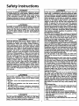
Safety Instructions
Improper installation, adjustment, alteration, service
or maintenance can cause DEATH, SERIOUS BODILY
INJURY, OR PROPERTY DAMAGE. Refer to this manual for assistance consult your local utility or call
Maytag Customer Service at 1-800-788-8899 for an
authorized servicer for further information,
|At the time of manufacture this water heater was pro-|
|vided with a combination temperature-pressures relief |
/valve certified by a nationally recognized testing laboratory that maintains periodic inspection of production of
listed equipment or materials, as meeting the requirements for Relief Valves and Automatic Gas Shutoff
Devices for Hot Water Supply Systems, and the latest
edition of ANSI Z21.22 andthe code requirements of
ASME. If replaced, the valve must meet the requirements of local codes, but not less than a combination
temperature and pressure relief valve certified as meeting the requirements for Relief Valves and Automatic
Gas Shutoff Devicesfor Hot Water Supply Systems,ANSI
Z21.22 by a nationally recognized testing laboratory
that maintains periodic inspection of production of listed equipment or materials.
The valve must be marked with a maximum set pressure
not to exceed the marked hydrostatic working pressure
of the water heater (150 Ibs./sq. in.) and a discharge
capacity not less than the water heater input rate as
shown on the model rating plate. (Electric heaters watts divided by 1000 x 3415 equal BTU/Hr. rate.)
Your local jurisdictional authority, while mandating the
use of a temperature-pressure relief valve complying
with ANSI Z21.22 and ASME, may require a valve model
different from the one furnished with the water heater.
_liance with such local requirements must be satisthe installer or end user of the water heater with
)rescribed temperature-pressure relief valve
the designated opening in the water heater
in place of the factory furnished valve.
For safe operation of the water heater, the relief valve
must not be removed from it's designated opening or
plugged.
The temperature-pressure relief valve must be installed
directly into the fitting of the water heater designated
for the relief va ve. Position the va ve downward and
provide tubing so that any discharge will exit only within 6 inches above, or at any distance below the structural floor. Be certain that no contact is made with any
live electrical part. The discharge opening must not be
blocked or reduced in size under any circumstances.
Excessivelength, over 30 feet, or use of more than four
elbows can cause restriction and reduce the discharge
capacity of the valve.
No valve or other obstruction is to be placed between
the relief valve and the tank. Do not connect tubing
directly to discharge drain unless a 6 air gap is provJd-
_, WARNING
HAZARD OF ELECTRICAL SHOCK! Before removing
any access panels or servicing the water heater,
make sure the electrical supply to the water heater
is turned "OFF". Failure to do this could result in
DEATH, SERIOUS BODILY INJURY, OR PROPERTY
DAMAGE.
AWARNING
]
HOTTER WATER CAN SCALD: Water heaters are I
intended to produce hot water. Water heated to a I
temperature
which will satisfy clothes washing, I
dish washing, and other sanitizing needs can scald I
and permanently injure you upon contact. Some l
people are more likely to be permanently injured by
hot water than others. These include the elderly,
children, the infirm, or physically/mentally
handicapped. If anyone using hot water in your home fits
into one of these groups or if there is a local code or
state law requiring a certain temperature water at
the hot water tap, then you must take special precautions, In addition to using the lowest possible
temperature settingthat
satisfies your hot water
needs, a means such as a mixing valve, should be
used at the hot water taps used by these people or
at the water heater, Mixing valves are available at
plumbing instructions
supply or hardware
stores. of
Follow
manufacturers
for installation
the valves.
Before changing the factory setting on the thermostat, read the "Temperature Regulation" section in
this manual,
AWARNING
INSULATING JACKETS: When installing an external
water heater insulation jacket on an electric water
heater:
• DO NOT cover the temperature-pressure
relief
valve,
ed. To prevent bodily injury, hazard to life, orproperty
damage, the relief valve must be allowed to discharge
water in quantities should circumstancesdemand. If the
discharge pipe is not connected to a drain or other suitable means, the water flow may cause property dam-
. DO NOT put insulation over the access covers or
any access areas,
• DO NOT cover or remove operating instructions,
and safety related warning labels and materials
affixed to the water heater,
_lqe"
e DischargePipe:
• Must notbe smaller in size than the outlet pipe size of
AWARNING
i
| Do not use this appliance if any part of it has been
|under water. An electrical short or malfunction could
Loccur. The water heater should be replaced,
dischargepipe.
both the temperature-pressure relief valve, and the
• Must terminate at an adequate drain.
• Must not have any valve between the relief valve and
tank.
the valve, or have any reducing couplings or other
restrictions.
• Must not be plugged or blocked.
• Must be of materl_allisted for hot water distribution.
• Must be installed so as to allow complete drainage of
2
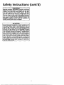
Safety Instructions (cont'd)
_,WARNING
WATER HEATERS EQUIPPED FOR ONE VOLTAGE
ONLY: This water heater is equipped for one type
voltage only. Check the rating plate near the bottom access panel for the correct voltage. DO NOT
use this water heater with any voltage other than
the one shown on the model rating plate. Failure to
use the correct voltage can cause problems which
can result in DEATH. SERIOUS BODILY INJURY. OR
PROPERTY DAMAGE. If you have any questions or
doubts consult your electric company.
ACAUTION
WATER HEATERS EVENTUALLY LEAK: Installation of[
the water heater must be accomplished in such a )
manner that if the tank or any connections should I
leak, the flow of water will not cause damage to the [
structure. For this reason, it is not advisable to install I
the water heater in an attic or upper floor. When
such locations cannot be avoided, a suitable drain
pan should be installed under the water heater.
Drain pans are available at your local hardware
store. Such a drain pan must have a minimum diameter of at least 1'/, inches greater than the water
heater diameter and must be piped to an adequate
drain. Under no circumstances is the manufacturer to
be held liable for any water damage in connection
with this water heater.
Table of Contents
Safety Instructions ...........................................................................................................
2-3
Table of Contents ............................................................................................................
4
Customer Information ...................................................................................................
s
Product Spedfications ....................................................................................................
s
Accessories and Tools Needed ......................................................................................
6
Accessories .......................................................................................................................................................................
TOOLS
.6
...................
,...,............................................
.________''''.._*_______'_.....'''________`____'_'''...''__._____'._.'''''''______________...'''______'_.._'_'6
Instructions for Installation ...........................................................................................
7-2e
Removing the Old Water Heater .......................................................................................................................................
Locating the New Water Heater ......................................................................................................................................
Typical Installation ...............................................................................................................................................................
The Convertible Lower Element ....................................................................................................................................
Water Piping ....................................................................................................................................................................
Temperature-Pressure Relief Valve ...................................................................................................................................
Filling the Water Heater .................................................................................................................................................
Converting the Lower Element .................................................................................................................................
Wiring Diagram .............................................................................................................................................................
Wiring ...............................................................................................................................................................................
Selecting Thermostat Location ........................................................................................................................................
Routing Wire Harness to Location ................................................................................................................................
Thermostat Removal ...........................................................................................................................................
Remote Thermostat Wiring at Water Heater ..................................................................................................
Remote Thermostat Installation and Wiring .........................................................................................................
Installation Checklist ..................................................................................................................................................
7
A_
8
.9
10
11
12
12-14
15
16
17
17
17,18
18-20
20,21
.22
Instructions for Operation .............................................................................................
23-26
J.
Temperature Regulatiom ..................................................................................................................................................
Temperature Conditions .................................................................................................................................................
Programming the Thermostat .....................................................................................................................................
.23
.,23
.23-26
Service and Maintenance ...............................................................................................
27-3a
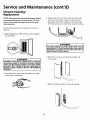
Temperature-Pressure Relief Valve Operation ....................................................................................................................
Draining ............................................................................................................................................................................
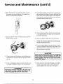
Element Cleaning and Replacement .........................................................................................................................
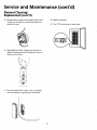
Drain Valve Washer Replacement ......................................................................................................................................
Service ...............................................................................................................................................................................
27
27
.28-30
31
31
Tr_ub_pes_ha_t_[ng..::..2::::::::::::::::::::::::::::..::::
Thermal Expansion .......................................................................................................................................................
Strange Sounds. ............................................................................................................................................................
Operational Conditions .............................................................................................................................................
Smelly Water ..............................................................................................................................................................
Air in Hot Water Faucets ............................................................................................................................................
.32
.32
32,33
.32
.32
Rumbling Noise ............................................................................................................................................................
High Temperature Shut OffSystem ......................................................................................................................
Not Enough Hot Water ................................................................................................................................................
Water is Too Hot ......................................................................................................................................................
32
32,33
33
.33
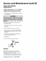
Thermostat Diagnostics ...............................................................................................................................................
Leakage Checkpoints ................................................................................................................................................
.34
35
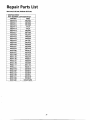
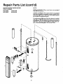
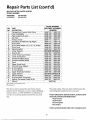
--RepairParts List ..............................................................................................................
37-39
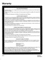
Warranty ............................................................................................................................
40
4
Customer Information
Thank
You
for purchasing a Maytag water heater.
Properly installed and maintained, it should give you years of
trouble free service. It is strongly suggested that this new
water heater be professionally installed, car Maytag Customer
Service at 1-800-788-8899 for recommended installers,
Abbreviations
Found
In This
Instruction
• The installation must conform with the instructions in this
manual; electric company rules; and Local Codes, or in the
absence of Local Codes, with the latest edition of the
National Electrical Code. This publication is available from
your local government or public library or electric company
or by writing Underwriters Laboratories, 333 Pfingsten
Manual
Road, Northbrook, IL 60062.
U.L.- Underwriters Laboratories, 333 Pfingsten Rd.,
Northbrook, IL 60062
• If after reading this manual you have any questions or do
National Electrical Code-This publication is available from
not understand any portion of the instructions, call Maytag
Customer Service at 1-800-788-8899 for an authorized
servicer.
your local government or pubfic library or electric company or
by writing to U.L above.
ANSI-American National Standards Institute
• CarefiAIy plan the place where you are going to put the
water heater. Correct electrical wiring and connections are
very important in preventing death from possible electrical
shock and fires.
• Read the "Safety Instructions" section, pages 2 and 3 of this
manual, first and then the entire manual caxefi_ly. If you
don't follow the safety rules, the water heater will not operate properly. It could cause DEATH, SERIOUS BODILY
INJURY AND/OR PROPERTY DAMAGE.
Examine the location to ensure the water heater compiles
with the "Locating the New Water Heater" section.
This manual contains instructions for the installation, operation, and maintenance of this electric water heater. It also
• For California installation this water heater must be braced,
contains warnings throughout the manual that you must
anchored, or strapped to avoid falling or moving during an
read and be aware of. All warnings and all instructions are
essential to the proper operation of the water heater and
your safety. Since we cannot put everything on the first few
pages, READ THIS ENTIRE MANUAL BEFORE
ATTEMPTING
TO INSTALL OR OPERATE THE
WATER HEATER.
earthquake. See instructions for correct installation procedures. Instructions may be obtained from the California
office of the State Architect, 400 P Street, Sacramento, CA
95814.
Massachusetts Code requires this water heater to be
installed in accordance with Massachusetts 248-CMR 2.00:
State Plumbing Code and 248-CMR 5.00.
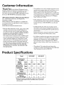
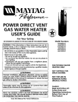
Product Specifications
Model
HE21250PC
Tank Capacity
In Gallons
Element
Wattage
at240Voh
Upper
Recovery Rate
In Gals Per Hr.
Upper
@90*FRise
Diameter
HE21282PC
50
80
3800
3800
I
Lower
3800
]
I
I
5500
3800
17.3
Height
Maximum Fuse or
Circuit Breaker Size
17.3
I
22"
5500
17.3
I
Lower
]
I
I
25
17.3
58.5"
I
25
26.25"
62"
20
30
20
30
12
10
12
10
Minimum
Wire Size (Gauge)*
*Wiring size based on standard 60°C copper wire. If distance from
fuse box to water heater is more than 90 feet, refer to your local
electrical code.
5
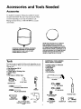
Accessoriesand Tools Needed
Accessories
To simpfify the installation Maytag has available the installation parts shown below. You may or may not need all of these
accessories
depending
Maytag Customer
rized installer.
on your type of installation.
Service at 1-800-788-8899
Call
for an autho-
(PARTNUMBER66001011) FORWATER
HEATERS
HAVING A DIAMETER20"
OR LESS,
DRAINPANSAVAILABLE
IN 22" DIAMETER
EXPANSIONTANKS FORTHERMALEXPANSION
CONDITIONSAVAILABLEIN 2 GALLON(PART
NUMBER 66001013) AND S GALLON(PART
NUMBER 66001014) CAPACITY
24" DIAMETER(PARTNUMBER66001105) FOR
WATERHEATERSHAVING A DIAMETER22" OR
LESSAND AVAILABLEIN 28" DIAMETER(PART
NUMBER66001012) FORWATERHEATERS
HAVING A DIAMETER26.25" OR LESS
TOOLS
ADDITIONAL
TOOLS NEEDED
WHEN SWEAT SOLDERING
You may or may not need all of these tools, depending on your
type of installation.
These tools can be purchased at your local
lVlaytag store.
• Pipe Wrenches
• Screwdriver
•
•
•
•
* Tubing Cutters or Hacksaw
• Propane Torch
• Soft Solder
(2) 14"
• Solder Flux
• Emery Cloth
• Wire Brushes
6 Foot Tape of Folding Rule
Garden Hose
Drill
Pipe dope or Teflon Tape
6 FOOTTAPE
GARDENHOSE
314_ WIRE BRUSH
SLOT-HEADSCREWDRIVER
-
PIPE
WRENCH
1/2" WIRE BRUSH
ROLLOF LEAD FREE
PHILLIPS
_
(SQUEEZE
PIPEDOPE
TUBE) SCREWDRIVER
_
ROLLOF TEFLONTAPE
(Use only on water connections)
_ SOLDER
SO.
_
ROLLOF EMERY
CLOTH
DRILL
6
PROPANETORCH
SOLDERFLUX
TUBINGCUTTER
Installation
Instructions
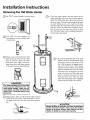
Removing the Old Water Heater
Turn "OFF" electrical supply to the water heater.
@
a. If you have copper piping to the water heater, the two
copper water pipes can be cut with a hacksaw approxithe water heater. This will avoid cutting off the pipes
too short. Additional cuts can be made later if necessary. Disconnect the temperature-pressure relief valve
drain line. When the water heater is drained, disconnect the hose from the drain valve. Close the drain
valve. The water heater is now completely disconnectmately four inches away from where they connect to
ed and ready to be removed.
_
@
T:::r
F[]'or
water
"hOe
meter.:hlh:a::t_::PuPlY
__C
tff°vtab:
Q_
a
to
water
Attach
hose
the
heater drain
valve and put the other end in a floor
heater drain valve. Open a nearby hot
water
drain faucet
or outdoors.
which will
Open
relieve
thepressure
water
in the water heater and speed draining,
_'li
_
_1_
t1
I_
]
Q
@b.
If you have galvanized pipe to the water
with a pipe wrench at the union in each
heater,Also
line.
loosen
disconnect
the twothegalvanized
piping remainpipes
ing to the water heater. These pieces
should be saved since they may be needed
Disconnect
the temperature-pressure
relief valve drain line. When the water
heater is drained, disconnect the hose
from the drain valve. Close the drain
__
_i WAR N IN G
valve may
avoid being
connections
water flow
any person.
valve.
water heater
nowwater
completely
when The
reconnecting
the is
new
heater.
disconnected and ready to be removed.
_
I-_-_-'1
be extremely
hot. To
scalded, make sure all
are tight and that the
is directed away from
Check again to make sure the electrical supply is turned
"OFF" to the water heater. Then disconnect the electriThe water passing out of the drain
_
cal supply connection from the water heater junction
_
box.
Mineral buildup or _y
in the old water heater.
have accumulated
This causes the water /
residue, if spilled out, could cause staining.
]
heater to bemuch heavier than normal and this I
__1_
7
Instructions for Installation (cont'd)
Locating The New Water
Heater
ACAUTION
I
WATER HEATERS EVENTUALLY LEAK: Installation of
the water heater must be accomplished in such a i
manner that if the tank or any connections
should I
You should carefiany choose an indoor location for the new
water heater, because the placement is a very important con-
leak,
the flow
of water
willit not
cause
damageto to
the I
structure.
For this
mason,
is not
advisable
install
the water heater in an attic or upper floor. When
such locations cannot be avoided, a suitable drain
pan should be installed under the water heater.
Drain pans are available at your local hardware
store. Such a drain pan must have a minimum diameter of at least 1'14inches greater than the water
heater diameter and must be piped to an adequate
drain. Under no circumstances ts the manufacturer or
Maytag to be held liable for any water damage in
connection with this water heater.
sideration for the safety of the occupants in the building and
for the most economical use of the appliance. This water
heater is not intended for outdoor installation,
Whether replacing an old water heater or purring the water
heater in a new location, the following critical points must be
observed.
1. The location selected should be indoors as close to and as
_kCAUTION
centralized with the water piping system as possible. This
water heater, as well as all water heaters, will eventually
leak. Do not install without adequate drainage provisions
where water flow will cause damage,
INSTALLATION IN RESIDENTIAL GARAGES: The water [
heater must be located and/or protected so it is not [
subject to phys cal damage by a mov ng veh tie.
[
2. The location selection must provide adequate clearances for
servicing and proper operation of the water heater.
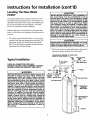
VACUUMRELIEF
REQUIRED
BYSOMECODES
(REFER
TOLOCALCODES)_
__
SHUTOFF
VALVE
CHECK ALL CONNECTIONS FOR LEAKS.
CONSULT THE LOCAL UTILITY COMPANY TO EXAM-
_OUTL
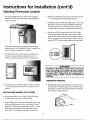
Typical
Installation
INE INSTALLATION FOR PROPRIETY AND SAFETY.
HOTTER WATER CAN SCALD: Water heaters are
intended to produce hot water. Water heated to a
temperature
which will satisfy clothes washing,
;=_
TEMPERED
WATE_D
OUTLET*MIXING
dish permanently
washing, and injure
other sanitizing
can Some
scald
and
you upon needs
contact.
people are more likely to be permanently injured by
hot water than others. These include the elderly,
children, the infirm, or physically/mentally
handicapped. If anyone using hot water in your home fits
into one of these groups or if there is a local code or
state law requiring a certain temperature water at
the hot water tap, then you must take special precautions. In addition to using the lowest possible
temperature settingthat
satisfies your hot water
needs, a means such as a mixing valve, should be
used at the hot water taps used by these people or
at the water
heater. Mixing
COLDWATERINLET
E_I
VALVE
PIPE INSULATION /
ELBOW
' L_--J_IE
_-J
_'J_'_J
_
|
__
]1
)
I
valves are available at
i
_-.[-_TEMPERATUREPRESSURE
RELIEF
VALVE
I
.i
_
_alumbing
cturers instructions
supply or hardware
for installation
stores. of
Follow
the valves.
manuBefore changing the factory setting on the thermostat, read the "Temperature Regulation" section in
this manual.
--DISCHARGE
PIPE
plug)(D°
not capor
I
8
JXPIPEINSULATION
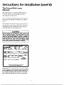
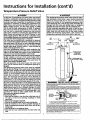
Instructions for Installation (cont'd)
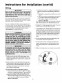
The Convertible
Element
Lower
The Upper Element, is a conventional 3800 watt element
which only operates at its rated wattage on 240 volts.
(See rating plate on water heater).
The Lower Element of the water heater can be converted
from operation at 3800 watts to 5500 watts on a 240 volt
system.
Read and follow water heater warnings and instructions. If
after reading these instructions in this manual, if you do not
understand any portion, call Maytag Customer Service at
1-800-788-8899 for an authorized servicer.
AWARNING
Before making the conversion to 5500 watts, check
the (1) power supply...must
be 240 volts, (2)
wiring...10 gauge AWG @ Type TW, 60oC or equivalent, and (3) Circuit breakers or fusing...capable of
30 amp loading. Also, the installation must conform
with this manual, local codes and electric utility
rules. Failure to comply can result in DEATH, SERIOUS BODILY INJURY, OR PROPERTY DAMAGE.
NOTE: Whether or not the dement conversion is made the
model rating plate must be marked. Using a hard point ink
pen, check the appropriate block within the model rating
plate, which is located adjacent to the lower access panel.
Instructions for Installation
(cont'd)
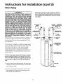
Water Piping
A WARNING
HOTTER WATER CAN SCALD: Water
heaters
NOTE: Your water heater is super insulated to minimize
heat lossfrom the tank. Further reduction in heat losscan
are
intended
to produce hot water. Water heated to a
temperature
which will satisfy clothes washing,
dish washing, and other sanitizing needs can scald
tnd permanently injure you upon contact. Some
_eople are more likely to be permanently injured by
lot water than others. These include the elderly,
children, the infirm, or physically/mentally
handicapped. If anyone using hot water in your home fits
into one of these groups or if there is a local code or
state law requiring a certain temperature water at
the hot water tap, then you must take special precautions. In addition to using the lowest possible
be accomplished
water heater.
by insulating the hot water lines fromthe
HOTOUTLET
TO
HOUSE
'_
i needs, a means such as a mixing valve, should be
temperature settingthat
satisfies your hot water
_-_
SHUT-OFF COLDINLET
VALVE (_) WATT_ER
LINE
i1_1 _-_n
_
%
_
_-_
u----_ []_
used
otw--''h'--OrTHO
TH--T
at the water
heater.
Mixing valves
available
at
plumbing
supply
or hardware
stores.are
Follow
manufacturers instructions for installation of the valves.
SWEAT COUPLING I
stat, read
Before
changing
the "Temperature
the factory setting
Regulation"
on thesection
thermo-in
this manual.
INsuFI_ION
I._1_
U
I I
U
3/4" THREADED---_--_/'_
the water heater. The water heater is equipped with V. inch
water
connections,shows the attachment of the water piping to
The illustration
NIPPLE
_i
If a water heater is installed in a closed water supply system;
such as one having a back-flow preventer, check valve, water
meter with a check valve, etc. in the cold water supply;
means shall be provided to control thermal expansion.
Contact the local utility or call Maytag Customer Service at
1-800-788-8899 for an authorized servicer on how to control this situation.
_
r
INSULATION
_ PIPE
3/4" THREADED
;
NIPPLE
J
.I TEMPERATUREfPRESSURE RELIEF
VALVE
r
[
b
ATCOUPLING
(
DISCHARGE
PIPE
(Do notcapor plug)
NOTE: If using copper tubing, solder tubing to an adapter
before attaching the adaptor to the cold water inlet connect/on. Do not solder the cold water supply line directly to the
cold water inlet. It will harm the dip tube and damage the
tank.
L_
1. Look at the top cover of the water heater. The water outlet
_
is
marked
hot.water
Connect
outlet
of the
heater.the hot water pipe to the hot water
_
2. Look at the top cover of the water heater. The cold water
inlet is marked cold. Connect the cold water pipe to the
cold water inlet of the water heater.
10
(
"_
_
-7T 6" AIRGAP
_ _'_
FLOORDRAIN
Instructions for Installation (cont'd)
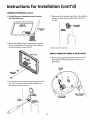
Temperature-Pressure Relief Valve
&WARNING
J
At the time of manufacture this water heater was providecl with a combination temperature-pressuresrelief va ve
certified by a nationally recognizedtesting laboratory that
maintains periodic inspection of production of listed I
equipment or materials, as meeting the requirements for
Relief Valves and Automatic Gas Shutoff Devices for Hot
Water Supply Systems, and the latest edition of ANSI
ZZ1.22 and the code requirements of ASME. If replaced,
the valve must meet the requirementsof local codes,but
not less than a combination temperature and pressure
relief valve certified as meeting the requirements for
Relief Valves and Automatic Gas Shutoff Devicesfor Hot
Water Supply Systems,ANSI Z21.22 by a nationally recognized testing laboratory that maintains periodic inspection
of production of listed equipment or materials.
The valve must be marked with a maximum set pressure
not to exceedthe marked hydrostaticworkJng pressureof
the water heater (150 Ibs./sq.in.) and a dischargecapacity
not lessthan the water heater input rate as shown on the
model rating plate. (Electric heaters - watts divided by
1000 x 3415 equal BTU/Hr.rate.)
Your local jurisdictional authority, while mandating the
AWARNING
7he temperature-pressure relief valve must be manually operated at least once a year. Caution should be
taken to ensure that (1) no one is in front of or
around the outlet of the temperature-pressure relief
valve discharge line, and (2) the water manually dis! charged will not cause any bodily injury or property
damage because the water may be extremely hot.
I If
after manually
therelease
valve, water,
it fails immedito cornpletely
reset and operating
continues to
ately close the cold water inlet to the water heater,
follow the draining instructions, and replace the
, temperature-pressure relief valve with a new one.
H_OT
_
CO<_LD
_--
_
PIPE'-_-_
INSULATION
L
_
The DischargePipe:
• Must not be smaller in size than the outlet pipe size of
the valve, or have any reducing couplings or other
restrictions.
Must not be plugged or blocked.
I : Must be
be of
installed
materialso
listed
as tofor
allow
hot water
complete
dislribution.
drainage of
both the temperature-pressure
reliefvalve,and the discharge pipe.
I,"
M ust
tank.
terminate
_
L.t
_j_.
CONDUIT_
use
ofZ21.22
a temperature-pressurerelief
complyingwith
ANSI
and ASME, may requirevalve
a valve
model different from the one furnished with the water heater.
Compliancewith suchlocal requirementsmust be satisfied
by the installer or end user of the water heater with a
locally prescribed temperature-pressure relief valve
installed in the designated opening in the water heater in
place of the factory furnishedvalve.
For safe operation of the water heater, the relief valve
must not be removed from it's designated opening or
pugged.
temperature-pressure relief valve must be installed
:ctly into the fitting of the water heater designated for
relief valve. Positionthe valve downward and provide
tubing so that any dischargewill exit only within 6 inches
above, or at any distance below the structural floor. Be
certain that no contact is made with any live electrical
part. The discharge opening must not be blocked or
treduced in size under any circumstances.Excessivelength,
over 30 feet, or use of more than four etbows can cause
restrictionand reducethe dischargecapacity of the valve,
No valve or other obstruction isto be placed between the
relief valve and the tank. Do not connecttubing directlyto
discharge drain unless a 6" air gap is provided.To prevent
bodily injury, hazard to life, or property damage, the relief
valve must be allowed to discharge water in quantities
should circumstancesdemand, If the dischargepipe is not
connected to a drain or other suitable means, the water
_
VALVE PIPE
_ _j_
_
3
,'
'
_
INSULATION
_
TEMPERATUREPRESSURE
RELIEF
VALVE
_ DISCHARGE
PIPE
_(Do notcapor plug)
\
!
_
_
[
k,
=_, ,; _
FLOOR
DRAIN
_ j
6"AIR GAP
E
BF-
r
WARNING
"RELIEF VALVE OPENING"
Thdswater
heateris
pf0_ded
_thar_mbmatJonTernpeca_Jr_Pressure
Relief
Valve
_sted
ascomplying
wi_
andlhecodete_JirementsofASME.
WI_ANSZ2
22andASME,mayrequ_'eavaJvemode
drlerentfromlheonelumshedv,_hthewaterheaer
Your
local
udsdic_lof,ai
a_, while
rnardafi_lhe
use
ofaTemoerature-Pressure
Rel_f
Val_
complying
a locallypr¢scnbedTemperature-Pr
C0mpliancewJlhsuc_lccalrequirementsmustbesa_s_edbylheinslal_r_e
essute ReliefValve ir_tailed in I_e des_gnateJ
openingin the water
_r
TANK
_; l_ ,_ACK_
1hesianda_dforReliefWives _uTd
AutomahcGas ShutoffDevicesforHotWaterSupplySYstems,
AJ_SZ21.22
TANK
FITFING
'/
__' '
BRASS
COUPLING
VALVE PROBE
MUST EXTEND
IN3"OTANK
TEMPERATURE
PRESSURE
_
_
RELtEF VAWE
BRASS
IPP
SHANK
_
_'_ ' _'_-_H
• Ifashod
shank
(less
than
2")temperature=pressure
relief
valve
istobeinstalled
_ _*_1,_,w_,_ _
_= _ ._
• if a longshank (2" or longer}is to be installed,do notusethe nippleand coupling
.=_, Temperature.Pressure
Temperature-Pressure
proteobve
equipmentrequiredbyIocaJcodes,butnottessthan
a cc_nbma
t_on
Relief
VaJvecertified_s
meetin the requirementsfor _elief Valves
=lnd
Au_o_,_ Gas ShutoffDevicesfc_Hot-WaterSupplySysle_s,_S 721 22bya nafionaJly
recognized_stmustbe oriented,prowdedwilhtubing,c_ol_eaviseinstalledsothatdischargeca_exit 0nlywilhin6 inches
at
an
adequate drain.
Must not have any valve between the relief va ve and
Ihe waterheater,
IPeReliefValve
mustnotberemoved
or p_ugged.
_Forsafeoperat_n
lab°t_d°_ _hatof
r_a_l_tail_
Pen°dieinspecb°r'
of pr°dt¢_°_
Ol listeds_uipr°entOI
materialsThe valve
see manualheading =Temperature-Pressure
Relief Valve' for installationand maintenanceof Relief
Valve,dischargepipeandolhel safetyp_ecauhons
._o_,,
oraa
t ny
distar¢e
below
_ sbuctural
floor,
and
cannot
cc_tact
any
Iwe
elecinc_r
pad"
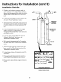
Instructions for Installation (cont'd)
Filling the Water Heater
WARNING
A
To £dl the water heater with water:
[
1. Close the water heater drain valve by turning the handle to
the right (clockwise). The drain valve is on the lower front
of the water heater.
tiBefore making the conversion to 5500 watts, checkll
I the (1) power supply...must
be 240 volts, (2) /
I wiring...10 gauge AWG @ Type TW, 60"C or equiva-|
]lent, and (3) Circuit breakers or fusing...capable ofl
[ 30 amp loading. Also, the installation must conform |
I with this ma nual, local codes and electric utility I
]rules. Failure to comply can result in DEATH, SERI-]
2. Open the cold water supply valve to the water heater.
NOTE: The cold water supplyvalve must be left open
when the water heater is in use.
3. To insure complete fdling of the tank, allow air to exit by
opening the nearest hot water faucet. Allow water to run
until a constant flow is obtained. This will let air out of the
]
[ OUS BODILYINJURY, OR PROPERTY DAMAGE.
water beater and the piping.
ACAUTION
Never use this water heater unless it is completely
full of water. To prevent damage to the tank and
heating element, the tank must be filled with
water. Water must flow from the hot water faucet
before turning "ON" power.
4. Check all new water piping for leaks. Repair as needed.
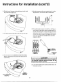
Converting the Lower
Element
These instructions only cover the conversion of the convert-
NOTE: Whether or not the element conversion is made the
ible dement, read this entire manual before attempting to
install or operate the water heater. The water heater is factory
set to operate at 3800 watts. The lower element can be convetted to operate at 5500 watts. Refer to "The Convertible
model rating plate must be marked. Using a hard point ink
pen, check the appropriate block vAthln the model rating
plate, which is located adjacent to the lower access panel.
Lower Element" section.
Necessary element conversion parts are located in a small bag
contained within the large plastic manual envelope attached
to the side of the water heater.
The Upper Element is a conventional 3800 watt element
which only operates at its rated wattage on 240 volts. (See rating plate on water heater).
The Lower Element
CONVERSION
PARTS
of the water heater can be converted
from operation at 3800 watts to 5500 watts on a 240 volt sys-
/_
If after reading these instructions and this manual, if you do
tern.
not understand any portion, call Maytag Customer Service at
1-800-788-8899 for an authorized servicer.
BUSSBAR
22
]
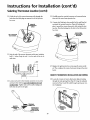
Instructions for Installation (cont'd)
Converting
(cont'd)
the lower
Element
1. Before beginning the conversion turn "OFF" electric
4. Remove the screws from terfninal 2 of the element, and
power supply to the water heater,
move the looped end of the wire aside.
@i,
WARNING
5. The buss bar is labeled 5500 W. Place the buss bar over terminals 2 and 3 with the 5500 W visible. Install the extra
HAZARD OF ELECTRICAL SHOCK! Before removing
any access panels or servicing the water heater,
make sure the electrical supply to the water heater
is turned "OFF". FAILURE TO DO THIS COULD
RESULT IN DEATH, SERIOUS BODILY iNJURY, OR
screw provided into terminal 3.
2. The convertible element is located behind the lower access
panel of the water heater. Remove the screw securing the
access panel, and remove panel.
PROPERTY DAMAGE.
must remain looped and now be placed (as shown) on top
of the buss bar, over the opening of terminal 2, and secured
using the remaining screw.
_,
6. The wire removed from terminal 2 has a looped end. It
3. Remove the flap of insulation to expose the opening.
7. Tighten terminals 2 and 3 to ensure proper electrical connection.
Failure to tighten terminal screws can cause a fire]
which can result in DEATH, SERIOUS BODILY INJURY,[
OR PROPERTY DAMAGE.
/
AWARNING
13
l
Instructions for Installation (cont'd)
Converting
(cont'd)
the Lower Element
8. Press the insulation back in place so that it completely covers the thermister and element.
10. Complete wiring to the water heater, or if completed, turn
"ON" electric power to the water heater after filling the
tank with water.
9. Replace the access panel.
Never use this water heater unless it is completely /
full of water. To prevent damage to the tank andJ
ACAUTION
]
Water must flow from the hot water faucet before|
turning "ON" power.
_P
__
heating element, the tank must be filled with water. |[
i4
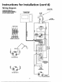
Instructions for Installation (cont'd)
Wiring Diagram
STANDARD WIRING FOR
2 WIRE LEAD WATER HEATERS
NON-SIMULTANEOUS
OPERATION
240 VOLT DOUBLE ELEMENT
TO
ELECTRIC
POWER SUPPLY
PROGRAMMABLE
CONTROL UNIT
AC 240
6_z
HI-TEMP
¢¢
,_
i
6-WIRE CABLE
z
<
=_
UPPER
THERMISTOR
m3
UPPER
O
6
,,n
J
HEATING
ELEMENT
4321
I "
' """J
TERMINAL CONNECTOR
FOR 5500 WATTS
RELAYS &
BOARD
THERMISTOR
FOR 3800 WA'I-rS
LOWER
HEATING ELEMENT
15
Instructions for Installation (cont'd)
Wiring
•i_ CAUTION
C. Flexible metal conduit or 3 metallic tubing shall be per-
Never use this water heater unless it is completely
full of water. To prevent damage to the tank and
heating element, the tank must be filled with
water. Water must flow from the hot water faucet
mitted for grounding if all the following conditions are
met:
1. The length in any ground return path does not exceed
6 feet.
before turning on power.
2. The circuit conductors contained therein are protected
by overcurrent devices rated at 20 amperes or less.
3. The conduit or tubing is terminated in fittings
approved for grounding.
For complete grounding details and all allowable exceptions,
refer to the latest edition of the National Electrical Code.
You must provide all wiring of the proper size outside of the
water heater. You must obey local codes and electric company
requirements when you install this wiring.
Ifyun are not familiar with electric codes and practices, or if
you have any doubt, even the slightest doubt, in your ability to
connect the wiring to this water heater, obtain the service of a
4.
competent electrician. Call Maytag Customer Service at
1-800-788-8899 for an authorized servicer,
A s andar 1/,,
t
d ,_ conauit opening has been made in the water
heater junction box for the conduit connection.
5. A wiring diagram (See "Wiring Diagram" Section) has been
suppfied showing the connections between the water heater
and the power supply. You can easily see the connection by
WARNING
removing the junction box cover on top of the water heater.
WATER HEATERS EQUIPPED FOR ONE VOLTAGE
ONLY: This water heater is equipped for one type
voltage only. Check the rating plate near the bottom access panel for the correct voltage. DO NOT
use this water heater with any voltage other than
the one shown on the model rating plate. Failure to
use the correct voltage can cause problems which
Connect red to red, black to black, and the ground wire to
the green ground screw in the junction box of the water
heater.
6. Use wire nuts and connect the power supplywiring to the
wires inside the water heater's junction box.
can result in DEATH, SERIOUS BODILY INJURY, OR
PROPERTY DAMAGE. If you have any questions or
doubts consult your electric company,
7. The water heater must be electrically "grounded" by the
installer. A green ground screw has been provided on the
water heater's junction box. Connect ground wire to this
A CAUTION
location.
If wiring from your fuse box or circuit breaker box
was aluminum for your old water heater, replace it
with copper wire. If you wish to reuse the existing
aluminum wire, have the connection at the water
Mayta_ Customer Service at 1-800-788-8899
authorized servicer.
8. Replace the wiring junction cover using the screw provided,
for an
WIRE
T
CONDUIT _
1. Provide a way to easily shut off the electric power when
breaker or fuse block in the entrance box or a separate disconnect switch.
/_
2. Install and connect a circuit directly from the main fuse or
circuit breaker box. This circuit must be the right size and
working
on the
beater. breaker.
This could
a circuitin
have its own
fusewater
or circuit
Referbetowith
the chart
,@GsGR_
the "Product Specifications" section for the correct size
wire and fuse or circuit breaker.
3. If metal conduit is used for the grounding conductor:
A. The grounding electrode conductor shall be of copper,
aluminum, or copperclad aluminum. The material shall
be of one continuous length without a splice or joint.
B. Rigid metal conduit, intermediate metal conduit, or
electrical metallic tubing may be used for the grounding
means if conduit or tubing is terminated in fittings
approved for grounding.
/
16
--
_
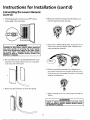
Instructions for Installation (cont'd)
Selecting
Thermostat
Location
1. The programmable thermostat control module is shipped
attached to the front of the water heater, located behind the
6. Probe for any obstruction in the partition. In a clear area drill
a %" hole through the wall at the selected location.
hinged cover panel.
7. Through this hole in the wall, drop a light chain or short chain
attached to a strong cord. Snag the cord with a hooked wire
from the basement. (In a home with no basement, drop the
cord from ceiling and snag it at the thermostat hole location.
8. Attach one end of the wiring harness to the cord. Pull the
cable through the hole in the wall so that 6 inches of cabh
protrudes. Other end of cable is to be routed back to the juncfinn box on top of the water heater (Step 21). Before proceeding, turn "OFF" the electric power supply to the water heater.
If this thermostat location is acceptable to the homeowner,
proceed directly to the "Installation Checklist" on page 22 and
then to "Temperature Regulation" on page 23.
2. The thermostat control module can also be installed next to
the home's heating or heating/coofing thermostat, or in
another convenient location remote from the water heater.
_WARNING
HAZARD OF ELECTRICAL SHOCK! Before removing I
any access panels or servicing the water heater, I
make
sure,the
waterresult
heater
is turned
OFFelectrical
. Failure supply
to do to
thisthe
could
in I
DEATH, SERIOUS BODILY INJURY, OR PROPERTY
DAMAGE.
THERMOSTAT
REMOVAL
3. The remote location should be about 5 feet above the floor
on any wall with good air circulation at average room ternperature,
9. Holding fingers along the top and thumb on bottom, between
the thermostat and wall plate, gently remove thermostat from
the wall plate. The thermostat will be installed at the selected
remote location in Steps 32 and 33.
ROUTING
WIREHARNESS
TOLOCATION
4. A wiring harness kit for up to 50 feet of wiring is available
j.._'_,
5. Before drilling a hole in the wall at the selected location, take
up floor moulding (quarter round or other) and drill a small
(see Repair
Parts
list) from
your
Dealer.
guide
hole for
sighting.
From
theMaytag
basement,
drill a V/' hole in
partition floor next to guide hole (in homes with no basement, drill a V/' hole through ceiling above the partition),
_'_
___
17
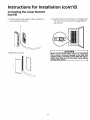
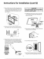
Instructions for Installation (cont'd)
THERMOSTAT REMOVAL (cont'd)
10. C_tte_u_y discozln_ witiRg harfleasternlJflltlconnector
frombackofthermostat,
13. Pressthe end of the thermostatcablebackinto the insulating
bushing.No other connectionswillbe made to this end of
TAT
_,
WIRING
HARNESS
BACKOF
THERMO_$_T.
INSULATING
__RAMBOLES
_
the cable.
RUSHING
TERMINAL
CONNECTOR
11. Removethe wallplate from the water heater by unscrewing
the two mountingscrews.The wall platewii1beinstalledat
the selected location in Steps 28 and 29.
14. Close and latch outer door.
REMOTE THERMOSTATWIRING AT WATERHEATER
15. Removemounting screwandrightjunction boxcover.Also
lift up andremoveblackplugon leftjunctionbox cover,
Discardplug.
BLACK
12. Looseneachscrewin the terminalconnectorandremove the
wire ends. The terminal connectorwillbe installed at the
/]
,i
selected remote location in Step 31.
MOUNTING
_7
SCREWS
_
W.R.NG
.AR.E_S
SLOTSSCREW
c<
_
GIPLUG
BOX COVER
TERMINAL
CONNECTOR
o
18
2
R,.HT'
BOXCOVER
\
Instructions for Installation (cont'd)
16. Find the loop of thermostat wiring cable (grey colored) inside
the junction box and pull it out.
LOOP
19. Strip the thermostat cable outer insulation back I_A inches.
Strip the ends % inch on each of the six colored wires.
_
m
ud
__
_
O
_
._
1.250"
J
20. A second terminal connector is provided in a small bag contained within the large plastic manual envelope attached to
the side of the water heater. Loosen each screw in the terminal connector. Insert the six colored wires of the thermostat
17. Cut the thermostat wiring cable in half at the top of the loop.
cable into the terminal connector and tighten each screw to
secure each wire. Be sure to arrange wires in exact color
sequence as showm
6-WIRE
CA"LE
Lu
z
_
=
_ =
TERMINAL
6
18. The wire side of the loop which does not have the red tape
A
2 1
_TCONNECTOR
TERMtNAL
( _
CONNECTOR
_E
THERMOSTAT
strip on it should be cut off or pressed into the junction box
A CAUTION
The six colored insulated wires must be installed in
the terminal connector exactly as shown for the
out of the way.
thermostat to operate correctly.
water heater in Step 8.
R_RTIApPE
I
ACTIc_
TH_AT
21. Locate the end of the remote thermostat cable routed to the
ALF
19
Instructions for Installation
(cont'd)
SelectingThermostatLocation(cont'd)
22. Guide the end of the remote thermostat cable through the
hole where the black plug was removed in the left junction
25. Carefully press the terminal connector and connected wires
down into the water heater junction box.
box cover.
26. A strain-relief bushing is also provided in the small bag that
contained the terminal connector. Open the bushing and
place it around the remote thermostat cable exiting the junction box. Press the bushing into the hole in the left junction
box cover,
X REMOTE
HERMOSTAT
CABLE
REMOTE
THERMOSTAT
INSULATING
STRAIN-RELIEF
BUSHING
TERMINAL
CONNECTOR
23. Strip the end of the remote thermostat cable outer insulation
back 11/4inches. Strip the ends 1/4inch on each of the six colored wires.
m
b-
ua
t-
u_
"_ _
_"
_
_t it
!_
!t
!t
_.250"
27. Replace the right junction box cover using the screw provid_t_SO"
heater,ed'
This completes the remote thermostat wiring at the water
28. Locate the 6 inches of remote thermostat cable protruding
through the wall opening (from Step 8). Using the wall plate
removed in Step 11, pull the cable through opening near center of wall plate.
24. Loosen each screw in the terminal connector one at a time
and insert wire with the same color insulatlon into each
nmnbered slot. Tighten each screw securely making sure
both wires in each slot are tight.
TERMINAL
REMOTE
THERMOSTAT
_/
_ff
CONNECTOR
/_Y_vt-J-
THERMOSTAT
CABLEfJ--/
_
r
_
\
CABLE
FROM
WATER HEATER
_
_TH'ER'MOSI"AT
CABLE-_
j
20
Instructions for Installation (cont'd)
29. Fasten wall plate loosely to the wall in position shown using
_.
CAUTION
the three screws provided in the plastic bag. Wall anchors are
The six colored
recommended for drywall installation. Place a level on top of
the wall plate, adjust until level, and then tighten screws to
secure wall plate.
the terminal
connector
exactly
thermostat
to operate
correctly.
_"--_"_-_
WALL
wires
must
be installed
as shown
for
in
the
32. Carefully plug the wired terminal connector to the mating
pins on the thermostat back. Connector will install in one
direction only as shown.
_
_-_rrH
insulated
ERMOSTA_-_,,
5
O.NGE/WH,TET.E--O T
SCREWS
30. Strip the remote thermostat
._
ORANGI_'_I_
GREEN/WHITE
TERMINAL
cable outer insulation back 11/4
CONNECTOR
inches. Strip the ends V4 inch on each of the six colored wires.
33. Place thermostat
,W--
_.
ua
zH _H _1
_.250"
_II_HmH_
GREEN
over wall plate, press firmly, and thermostat
will snap into place on the wall plate.
,
,.i
-
31. Using the terminal connector removed in Step 12, insert the
six colored insulated wires in the remote thermostat cable
into the numbered
slots in the terminal connector
and tight-
34. Turn "ON" electric power m water heater.
en each screw to secure each wire. Be sure to arrange wires in
exact color sequence as shown.
6-WlRECABLEI
iz_--"
__0 _ua_--_"
t_1_"
i 5 I_
2
I _ _ qI & _
TERMINAL
CONNECTOR
TERMINAL
_I__._,_CONNECTOR
_( (
35. Read Temperature Regulation Warning
Settings, then proceed to Programming
THERMOSTAT
_E
21
and Temperature
the Thermostat.
Instructions for Installation (cont'd)
Installation
Checklist
1. Whether or not the element conversion is made, the
model
be marked.
point ratink
pen,rating
checkplate
the must
appropriate
blockUsing
withina hard
the model
ing plate, which is located adjacent to the lower access
panel.
H_OT
__...._
_
COLD
_
2. Is the fuse or circuit breaker size correct as shown in the
chart m the Product Specifications
CONDUIT
section.
-
I
3. Are the wires from the circuit breaker or fuse service to the
TEMPERATUREPRESSURE
RELIEF
VALVE
/
/
water heater's junction box on the correct wire size (gauge)
as shown in the chart in the "Product Specifications" section?
4. Is the new temperature-pressure
--DISCHARGEPIPE
(Do not capor
relief valve properly
installed, and piped to an adequate drain? See
"Temperature-Pressure Refief Valve" in the "Instructions
for Installation" section.
plug)
5. Is the water heater completely filled with water? See
"Filling the Water Heater" instructions in the
Instructmns for Installatton sectton.
I 6"AIR GAP
6. Will a water leak damage anything? See "Locating the
New Water Heater" in the "Instructions for Installation"
section.
FLOOR
DRAIN
7. Are the cold and hot water lines connected to the water
heater correctly? See "Water Piping" instructions in the
Instructzons for InstaUatmn section.
8. Is there adequate clearance for maintenance around the
water beater?
9. If the programmable thermostat has been moved to a
remote location, has the wiring been done correctly?
10. Do you need to call your electric company to check your
wiring?
_
'_ _* ,,_,'_,_
" _
w_
I_I_IqUCTION
® Mayteg isa Trac_ner k ol Mayt_l Cotporabon
is used Und¢_-Lk_*.iso*o 8tale InduslT_es,
Ino
MODEL RATING PLATE
22
Instructions for Operation
Temperature Regulation
Programming the Thermostat
AWARNING
Before programming
HOTTER WATER CAN SCALD: Water heaters are
intended to produce hot water. Water heated to a
the"Temperature
the settings on the thermostat,
read
Regulation" section again.
This new programmable thermostat technology makes it possible for you to enjoy all the benefits of hot water whenever
you need it and save the cost of heating water when you don't
temperature
will sanitizing
satisfy clotheswashing,
dish washing, which
and other
needs can scald
and permanently injure you upon contact. Some
people are more likely to be permanently injured by
hot water than others. These include the elderly,
children, the infirm, or physically/mentally
handi-
need it.
Simple and easy to use, the programmable control has three
capped. If anyone using hot water in your home fits
into one of these groups or if there is a local code
or state law requiring a certain temperature water
at the hot water tap, then you must take special
basic modes of operation:
grecautions.
In addition to using the lowest possile
temperature
setting such
that assatisfies
hot
water needs,
a means
a mixingyour
valve,
should be used at the hot water taps used by these
people or at the water heater. Mixing valves are
is unoccupied and there is no need for hot water.
3. Programmable mode - can be programmed for up to 24
hour a day, 7 days a week with 4 set periods a day.
available
at plumbing instructions
supply or hardware
stores.
Follow manufacturers
for installation
of
the valves,
Override is an optional setting that allows for temperature
1. Manual mode - a set and forget operation.
2. Vacation mode- for those occasions when the residence
adjustments during a given time period. This setting reverts
back to the previous mode of operation upon completion of
the designated override time period.
1
AWARNING
Never allow small children to use a hot water tap, /
or to draw their own bath water. Never leave a [
child or handicapped
person unattended
in a bath- I
tub or shower.
]1
time clock (12 hr. clock or 24 hr. military), temperature scale
(°F to °C), default heating setpoint, vacation setpoint and
Option menu
maximum
heating
is a mode
setpoint.
to change the factory setting for the
DATE AND
TIME
SETTING:
Your new programmable control comes complete with a day of
Temperature Conditions
VERY LOW-
HOT-
VERYHOT-
A thermostat setting of 120°F will supply hot
water at the most economical temperatures.
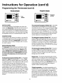
the week and digital clock display. These settings are changed
using the day and time keys on the control pad. To adjust day
and/or time, depress the appropriate key button. The day of the
week scrolls left to right on the display as the "DAY" button is
depressed. The time setting can be adjusted by scrolling forward or backward using the + and - of the "TIME" button.
The clock is based on a 24-hour rolling display with AM and
PM appearing below the hour and minute characters.
The thermostat maximum temperature is
CONSTANT
160°F. It is recommended that the temperalure be set lower whenever possible.
The constant display screen shows the water temperature
"WATER TEMP" inside the tank. It is continually on display until interrupted by a reprogram procedure, but reappears
after 20 seconds of inactivity.
The thermostat minimum setback temperalure is 60017.
NOTE: Water temperature range of 120"-140"F recommended by most dishwasher manufacturers.
MODE
TEMPERATURE
DISPLAY:
CHANGE
To change the mode-of-operation depress the "MODE" button at the bottom of the control. The mode display will change
by scrolling from top to bottom with the Auto mode appearing
on the top of the column, followed by the Manual mode in the
middle and finally the Vacation mode at the bottom. Continue
to change between mode settings by depressing the "MODE"
button until the desired setting is displayed.
23
Instructions for Operation (cont'd)
Programming
Normal
the Thermostat
(cont'd)
Display
Pro aram
Display
i _
,Tllc _ ,
_
:-'--'--TIME
m
_ MAVI'AG
I_
ll_
_
_PNOGI_M
Bu'n'ON
_ glDtlIP
BUTTON
_
L_--_
MAYrAG
i
LJmm
_"
i
MANUAL MODE
The most basic operation of the Intelligent water heater thermostat is the Manual Mode. With this mode the thermostat is
set at a desired temperature and the water heater operates to
maintain that temperature. The Intelligent Maytag water heater
utilizes a special sensing device in the control system that allows
The second period to proa'ramis Monday"Day _ - the method
of setting the time and temperature are the same for all four
selected periods of the day. The second period designated "Dav"
can be set to a reduced temperature (70°17or lower) due to the
lack of need for hot water, assuming no one is at home during
the day. If everyone leaves at 9:30 AM, this time can be entered
for temperature accuracy to be maintained at plus or minus IOF.
into the program and the heating elements would not activate
until the temperature in the tank dropped to 70°F.
VACATION MODE
Vacation mode is used whenever the residency is unoccupied for
a considerable length of time (2-days or longer) and hot water is
not needed. By selecting the Vacation Mode the water heater
will maintain a reduced setting of 80 degrees until a new operation mode is selected,
The third period to progs'am is Monda.v"Eve" - this period is
designated "Eve would usually begin when people arrive home
from their daily activities. The temperature for this period can
be adjusted to a normal hot water setting considering evening
demand like washing dishes or clothes. For example if 1250F is
the chosen temperature to have at 5:30 PM then these settings
would be entered into the program.
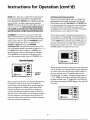
PROGRAMMABLE
MODE
The Auto mode selection permits the water heater to be programmed for four periods a day, 24-hours a day and 7-days a
week. To begin pro_amming, depress the "MODE" button
until the AUTO selection appears in the display. To activate
the Program Mode depress the "PROGRAM" button at the
top of panel. The pro_amming mode should appear as the
next display.
The fourth period to prommm is Monday"Nite" - this period
is designated "_NRe"and is usually the beginning of decreased
hot water needs as the residents retire for the night. In the
example the temperature would be set for 70°17or lower with
the begin time set at 11:00 PM.
Prom-am Co W - The first day of programming has now been
completed. If each succeeding day of the workweek requires the
same desired settings as those just programmed for Monday,
these settings can be copied to the remaining four days of the
week by depressing and holding the "PROGRAM" button for
several seconds. In this manner the first day's settings are
repeated to aUfour remaining weekdays.
The first period to program is Monday"Morn" - this period is
designated as "Morn". By depressing the + or - of the "TIME"
button, the owner can choose the target rime for the water to be
at a specific temperature. The heating dements _11 be activated
15 minutes before the target time to heat the water to the
desired temperature. For example, if 6:00 AM is the time the
occupant desires 130°F water for bathing, the time on the programmed display word be set for 6:00 AM. The next selection
to program is the desired water temperature to have for morning
activities. In this example the temperature would be set to 130°F
by depressing either the up (•) arrow or the down ( • ) arrow,
located next to the display pand, untL!the target temperature is
displayed,
Weekendggggtla!_!hlg
- the weekend programming can be
set different than the weekday settings, if desired. Saturday and
Sunday can be separately programmed by advancing the program selection to the day marked "SA" and/or "SLY'. The steps
described above for programming the four periods per day can
be repeated for the weekend only using different times and temperatures to provide desired water temperatures when needed on
the weekend.
24
Instructions for Operation (cont'd)
ERASE is the option that can delete all the settings that had
OPTIONAL
been programmed previously. While in the programmable
There arefive optional settings the owner can change in the
SETTING CHANGES
mode, depressing the "ERASE" button will delete a particular
time period that is on display. Depressing and holding the
"ERASE" button down for several seconds will erase all the settings for an entire week. This procedure should be administercd carefully, as erasing the entire week's progr'ammed set-
programmable control module. To advanceto the Optional
Setting Mode, depress the "PROGRAM" and "MODE" buttons simultaneously for four seconds. Four zeros should appear
in the upper left hand corner (0000) and a large number 1
should appear in the bottom right-hand corner. This indicates
tings will necessitate a complete l'eprom'amming procedure,
the optional menu is on the type of time setting.
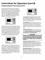
OVERRIDE is an option that can be used to temporarily
adjust water temperature for a specific length of time. If for
example there is a need for higher water temperatures during a
The first optional mode (1) setting involves the type of time
that will appear on the clock display. The default setting is the
normal twelve-hour clock. For military time depress either + or
specific number of hours or days, the "OVERRIDE" button
- of the "TIME" button until the description 0001 appears in
can be depressed. The first screen to be displayed is the
HOURS and DAYS time menu and DESIRED
TEMPERATURE. The default time period is 3 hours. This
time can be adjusted upward or downward by using the + or - of
the "TIME" button. After holding the + "TIME" button
the upper-left hand comer. To change back to normal time in
optional setting 1 depress either (+ or -) of the time buttons
until 0000 appears in the upper left-hand corner.
beyond 24 hours the hours and days designation will appear.
The OVERRIDE can be adjusted for both days as well as
hours. The maximum number of days to OVERRIDE is 99.
_
Override Display
_
L_-_MAWA6
|
_
The second optional mode (2) setting involves the temperature
scale. To change to the temperature setting option, depress the
_w,_
L_'_
JVJ_Y
I'AG
_m
J_
i
up or down arrow button until the large number 2 appears in
the lower right hand corner, The default setting is in the
Fahrenheit scale. To change to Centigrade, depress either + or
- of the "TIME" button until the description 0001 appears in
the upper-left hand corner. To change back to the Fahrenheit
--OVERRIDE
|
BU1TON
iJ
After setting the time duration, the override temperature can
be adjusted by using the up ( • ) arrow or the down (•)
scale, repeat the procedure until 0000 appears in the upper-left
hand corner.
arrow, located next to the display panel, until the target temperature is displayed. For example, if guests arrive for the
weekend and warmer water temperatures are desired, the
occupant may adjust the temperature setting to 130"F for 2
days and 10 hours. This would control the target temperature
until the completion of the designated time and return the
thermostat to the program control that had been in operation
before the override was implemented.
i,_
_'_MAYFAG
25
_
_
_
:|
Instructions for Operation (cont'd)
Programming the Thermostat (cont'd)
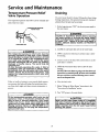
The third optional mode (3) setting involves the default ternperature set point for the control. To be in this mode, depress
the up ( • ) arrow or the down (•) arrow until a large number 3
appears in the lower right-hand corner. The default temperature
_-
--
=-
from the factory is 120°F. This will appear in the upper-left
hand corner as 0120. To change the default setting, depress
either
- of the "TIME" button until the desired default
temperature is displayed in the upper left-hand comer. The
k'_ MAYrAG
range for set point temperature is 80°F to 160°E
----
i
perature setting. This is factory set at 800F or 0080 in the upper
left-hand corner. To change the vacation default setting, make
sure the optional mode is in the number (4) setting by depressing the up (•) arrowor the down ( • ) arrow button until a
large number 4 is displayed in the lower right-hand corner. To
change the vacation temperature default setting, depress either +
or - of the "TIME" button until the desired vacation temperature is achieved in the upper left-hand comer of the display.
The range for vacation default setting is 60°F to 1200E
[
,,,
A WARNING
HAZARD OF ELECTRICAL SHOCK! Before removinc
any access panels or servicing the water heater
make sure the electrical supply to the water heate=
is turned "OFF". Failure to do this could result in
DEATH, SER OUS BOD LY NJURY, OR PROPERTY
DAMAGE.
....
=_
eJ_
_
"PWR" fPOWER) BUTTON is a button at the right-hand
bottom of the panel which will activate or deactivate the display
panel. It will not turn offthe power to the water heater and
will not kill the uower to the heatin_ elements.
-
..
k'_ MAYI'AG
;[
SCALD WARNING is a flashing displaywarning any time
the temperature is adjusted above 120°E It represents an industry warning that water ternperatuses above 120°F represent a
scald hazard when skin surface is exposed for a small amount of
time. This is a warning and can not be removed from the screen
display.
The fourth optional mode (4) setting involves the vacation tem-
-
_
using the above prescribed procedures.
= = ]!
MAYFAG
]
[
|
To return to regular operation of the program control, depress
the "PROGRAM" and "MODE" butt ons sire ultan eously
again until the normal display appears. All the optional settings
that were revised will remain until they are once again reset by
_._
_
i
_
_
"
ELECTRICAL
POWER
OUTAGES will not effect the
Intelligent programming or control settings. The unit has a battery backup that maintains the programmed settings until the
electrical power is restored. At the time power is restored the
program _ again display the settings and information that had
been available before the loss of power.
The fifth optional mode (5) setting involves the maximum ternperature set point. To he this mode, depress the up (_,) arrow
or the down (•) arrow while in optional setting sequence until
a large number 5 is displayed in the lower right-hand corner.
The default factory maximum set point is 1600F or 0160 in the
DRY FIRE PREVENTION
is a feature that has been programmed into the lntelllgent water heater. Should someone
install or service the water heater and forget to ill/the tank, the
unit will sense a rapid heat cycle beyond normal expectations
and disable the energy. A message will be displayed on the
screen to add water, at which time the unit can be re-energized.
upper left-hand comer. To change this setting depress either +
or - of the "TIME" button until the desired maximum set point
is achieved in the upper left-hand comer. The range for maximum set point is 100°F to 160°E
26
Service and Maintenance
Temperature-Pressure
Relief
Draining
Valve Operation
The temperature-pressure
The water heater should be drained if being shut down during
relief valve must be manua//y oper-
freezing temperatures. Also periodic draining and cleaning of
ated at least once a year.
sediment from the tank may be necessary.
1. Before beginning turn "OFF" the electtic power supply to
the water heater.
TEMPERATURE-PRESSURE
RELIEF
VALVE
HAZARD OF ELECTRICAL SHOCKi Before removing
any access panels or servicing the water heater,
make sure the electrical supply to the water heater
s turned "OFF". Failure to do this cou d result n
DEATH, SERIOUS _WARNING
BODILY INJURY, OR PROPERTY
DAMAGE.
DISCHARGE PIPE
2. CLOSE
the cold water inlet valve to the water heater.
AWARNING
The temperature-pressure
relief valve must be
manually operatedat
least once a year. Caution
should be taken to ensure that (1) no one is in front
of or around the outlet of the temperature-pressure relief valve discharge line, and (2) the water
manually discharged will not cause any property
damage
or bodily injury. The water may be
3. OPEN a nearby hot water faucet and leave open to allow
for draining.
4. Connect a hose to the drain valve and terminate to an adequate drain or outdoors.
extremely hot.
If after manually operating the valve, it fails to
completely reset and continues to release water,
5. OPEN the water heater drain valve to allow for tank
draining.
immediately close the cold water inlet to the water
heater, follow the draining
instructions,
and
replace the temperature-pressure relief valve with
a new one.
NOTE: If the water heater is going to be shut down and
drained for an extended perind, the drain valve should be
left open with hose connected allowing water to terminate m an adequate drain.
Failure to install and maintain a new properly listed temperature-pressure relief valve will release the manufacturer from
6. Close the drain valve.
any claim which might result from excessive temperature or
pressure.
7. Follow "Filling the Water Heater" instructions in the
"Instructions for Installation" section.
8. Turn "ON" power to the water heater.
AWARNING
If the temperature-pressure
relief valve on the
ippliance weeps or discharges periodically, this
nay be due to thermal expansion. Your water
_eater may have a check valve installed in the
water line or a water meter with a check valve. Call
Maytag Customer Service at 1-800-788-8899 for an
authorized servicer. Do not plug the temperaturepressure relief valve.
_,CAUTION
Never use this water heater unless it is completely
full water. To prevent damage to the tank and heating element, the tank must be filled with water.
Water must flow from the hot water faucet before
turning "ON" power.
27
Service and Maintenance (cont'd)
Element Cleaning/
Replacement
NOTE: These instructions are written for element cleaning
and element replacement for the lower element. If it is necessary to clean or replace the upper element, then repeat
these instructions,
3. Attach a hose to the water heater drain valve and put the
other end in a floor drain or outdoors. Open the water
heater drain valve. Open a nearby hot water faucet which
will relieve pressure in the water heater and speed draining.
To remove the element from your tank in order to clean or
replace it:
I1[
11
Ill
II|
1. Before beginning turn "OFF" the electric power supply to
the water heater.
The water passing out of the drain valve may be
extremely hot. To avoid beingscalded, make sure all I
connections are tight and that the water flow is
d rected away from any person.
_,WARNING
]
%
4. Remove the two screws securing the access panel, and
AWARNING
remove panel.
HAZARD OF ELECTRICAL SHOCK! Before removing
any access panels or servicing the water heater,
make sure the electrical supply to the water heater
is turned "OFF". Failure to do this could result in
DEATH, SERIOUS BODILY INJURY, OR PROPERTY
DAMAGE.
IIII
_
2. Turn offthe water supply to the water heater at the water
shutoff valve or water meter.
-
5:.Remove the flap of insulation to expose the opening.
28
Service and Maintenance (cont'd)
6. Upper Element Only - Lift out the tab as shown to unclip
10. A new gasket should be used in all cases to prevent a pos-
the terminal cover from the high fimit. The terminal cover
sible water leak. (See Element Gasket in the Repair Parts
can now be removed from the high fimit.
Chart). Place the new element gasket on the thread side
of the cleaned or new element and screw into tank, securing tightly using an element wrench.
11. Close the water heater drain valve by turning the handle
to the right (clockwise). The drain valve is on the lower
front of the water beater.
"--o
7. Disconnect the two wires on the element and unscrew the
old element from the tank.
12. Open the cold water supply valve to the water heater.
when the water heater is in use.
13. To insure complete filling of the tank, allow air to exit by
opening the nearest hot water faucet. Allow water to run
until a constant flow is obtained. This will let air out of
the water heater and the piping.
NOTE: The cold water supply valve must be left open
_'_
8.
A,CAUTION
Never use this water heater unless it is completely
full of water. To prevent damage to the tank and
heating element, the tank must be filled with water.
Water must flow from the hot water faucet before
turning "ON" power.
Clean the area around the element opening. Remove any
sediment from or around the element opening and inside
the tank.
9.
If you are cleaning the element you have removed, do so
by scraping or soaking in vinegar or a de-liming solution,
14. Check element for water leaks. If leakage occurs, tighten
element or repeat steps 2 and 3, remove element and
reposition gasket. Then repeat steps 11 through 15.
Replacement elements must (1) be the same voltage and (2) no greater wattage than listed on the
mode rating p ate AWARNING
aft xed to the water heater.
I
29
Service and Maintenance (cont'd)
Element Cleaning/
Replacement (cont'd)
15. Reconnect the two wires to the element and then check
to make sure the high limit remains firmly against the
surface of the tank.
18. Replace access panel.
19. Turn "ON" electric power to water heater.
%
16. Upper High Limit Only - Replace terminal cover on
high limit making sure that the locking tabs on the terminal cover are in place.
E
T i_,r
Tc _
17. Press the insulation back in place so that it completely
covers the thermistor, upper high limit and element.
30
Service and Maintenance (cont'd)
Drain Valve Washer
Replacement
NOTE:
For replacement,
use a '%1'x ly,,x %"thick washer
available at your nearest hardware store. For ordering a
replacement washer, refer to the "Repair Parts" section.
1. Before beginning turn "OFF" the electrical power supply
to the water heater.
&WARNING
HAZARD OF ELECTRICAL SHOCK[ Before removing
any access panels or servicing the water heater,
make sure the electrical supply to the water heater
is turned "OFF". Failure to do this could result in
DEATH, SERIOUS BODILY INJURY, OR PROPERTY
DAMAGE.
2. Follow "Draining" instructions in the "Service and
Maintenance section.
3, Turning counter clockwise, remove the hex cap below the
screw handle.
4, Remove the washer and put the new one in place.
5, Screw the handle and cap assembly back into the drain
valve and retighten using a wrench. DO NOT OVER
TIGHTEN.
6. Follow "Filling the Water Heater" instructions in the
"Instructions for Installation" section.
7. Check for leaks.
8. Turn "ON" electric power to the water heater•
_
_
HANDLE
AND
CAP
ASSEMBLY
_WASHER
Service
Before calling for repair service, read the "Start Up
Conditions" and "Operational Conditions" found in the
"Troubleshooting" section of this manual.
If a condition persists or you are uncertain about the operation of the water heater, let a qualified person check it out.
Call Maytag Customer Service at 1-800-788-8899.
31
Troubleshooting
Start Up Conditions
THERMAL
EXPANSION
SmeUy water may be eliminated or reduced in some water heater
models by replacing the anode(s) with one of less active material,
and then chlorinating the water heater tank and all hot water
fines. Call Maytag Customer Service at 1-800-788-8899 for an
authorized servicerfor further information concerning an Anode
Replacement Kit #66001068 and this Chlorination Treatment.
Water supply systems may, because of such events as high line
pressure, frequent cut-offs, the effects of water hammer
among others, have installed devices such as pressure reducing
valves, check valves, back flow preventers, etc._to control
these types of problems. When these devices are not equipped
with an internal by-pass, and no other measures are taken, the
devices cause the water system to be closed. As water is heated, it expands (thermal expansion) and dosed systems do not
allow for the expansion of heated water,
If the smelly water persists after the anode replacement and chlorinafion treatment, we can only suggest that continuous chlorination and filtering conditioning equipment be considered to efimihate the water problem.
The water within the water heater tank expands as it is heated
and increases the pressure of the water system. If the relieving
point of the water heater's temperature-pressure refiefvalve is
reached, the valve will relieve the excess pressure. The temperature-pressure relief valve is not intended for the constant
Do not remove the anode leaving the tank unprotected. By
doing so, all warranty on the water heater tank is voided.
relief of thermal expansion. This is an unacceptable condition
and must be corrected.
[
A WARNING
/HYDROGEN GAS: Hydrogen gas can be produced in
|a hot water system that has not been used for a
|long period of time (generally two weeks or more).
/Hydrogen gas is extremely flammable and explo_sive. To prevent the possibility of injury under these
conditions, we recommend the hot water faucet be
_opened for several minutes at the kitchen sink
before any electrical appliances which are connected to the hot water system are used (such as a dishwasher or washing machine). If hydrogen gas is present, there will probably be an unusual sound similar to air escaping through the pipe as the hot
water faucet is opened. There must be no smoking
or open flame near the faucet at the time it is open.
"AIR"
It is recommended that any devices installed which could create
a closed system, have a by-pass and/or the system have an
expansion tank to relieve the pressure built by thermal expansion in the water system.Expansiontanks are availablefor
ordering through the Maytag Customer Service. Contact the
local water supplier and/or call Maytag Customer Service at
1-800-788-8899 for an authorized servicer for assistance in
controlling thesesituations,
STRANGE SOUNDS
IN HOT WATER
RUMBLING
Possible noises due to expansion and contraction of some
metal parts during periods of heat-up and cool-down do not
represent harmful or dangerous conditions.
FAUCETS
NOISE
In some water areas, scale or mineral deposits will build up on
your heating elements. This buildup will cause a rumbling
noise. Follow "Element Cleaning/Replacement"
instructions
Operational Conditions
to clean and replace the elements.
SMELLY WATER
HIGH
In each glssslined water heater there is installed at least one anode
rod (see parts section) for corrosion protection of the tank,
Certain water conditions will cause a reaction between this rod
The water heater has a high limit shut offsystem with a reset
button located above the upper element.
and the water. The most common complaint associated with the
anode rod is one of a "rotten egg smell". This odor is derived from
hy&ogen sulfide gas dissolved in the water. The smell is th_ result
of four factors which must all be present for the odor to develop:
Follow the resetting instructions which refer to the high limit
behind the access panel.
a. a concentration of sulfate in the supply water.
b. tittle or no dissolved oxygen in the water.
c. a sulfate reducing bacteria within the water heater. (This
harmless bacteria is non-toxic to humans.)
d. an excess of active hydrogen in the tank. This is caused by
the corrosion protective action of the anode.
32
TEMPERATURE
SHUT
OFF SYSTEM
Troubleshooting (cont'd)
Operational Conditions (cont'd)
HIGH
TEMPERATURE
SHUT OFF SYSTEM
NOT
1. Before beginning, earn "OFF" electrical power supply to
1.
the water heater,
ENOUGH
OR NO HOT WATER
In a new installation, the water heater may not be properly connected. Make sure the cold water supply valve is
open. Review and check piping installation. Make sure
that the cold water fine is connected to the cold water
inlet to the water heater and the hot water Iine to the hot
water outlet on the water heater.
2.
Make sure the electrical supply to your water heater is
"ON".
3.
Check for loose or blown fuses in your water heater circuit. Circuit breakers weaken with age and may not handle their rated load and should be replaced.
4.
Make certain the disconnect switch, if used, is in the
......
ON postuon.
5.
Check to see the electric service to your house has not
been interrupted. If this is the case, contact the electric
_WARNING
HAZARD OF ELECTRICAL SHOCK! Before removing
any access panels or servicing the water heater,
make sure the electrical supply to the water heater
is turned "OFF". Failure to do this could result in
DEATH, SERIOUS BODILY INJURY, OR PROPERTY
DAMAGE.
2. Remove the two screws securing the upper access panel and
remove panel,
company.
6.
Is the programmable thermostat set to the desired temperature? See "Temperature Regulation" section.
7.
If you had experienced very hot water and now no hot
water, the problem may be due to the high temperature
3. Remove the flap of insulation to expose the opening,
4. Reset the high limit by pushing in the red button marked
"RESET".
shut offsystem. See "High Temperature Shut Off
System" in the "Troubleshooting" section.
I @_ll I
RESETBU_'ON
8.
During very cold weather, the incoming water win also be
colder and it will require a longer time to become heated.
9.
The hot water usage may exceed the capacity of the water
heater. If so, wait for water heater to recover after abnormal demand. Also examine pipes and faucets for possible
water leaks.
5. Press the insulation back in place so that it completely covers the high limit and dement.
10. If you can not determine the problem, then call the
Maytag Service Department.
6. Replace the upper access panel.
WATER
IS TOO
HOT
7. Turn "ON" electric power to the water heater.
Adjust the thermostat to a lower setting. See the
a_ CAUTION
If the high limit must be reset again, call Maytag I
Customer Service at 1-800-788-8899 for an autho-[
rized,,servicer to find out why the high limit turned I
OFF the electric power.
J
"Temperature Regulation" section on page 23.
33
Troubleshooting (cont'd)
Operational Conditions (cont'd)
THERMOSTATDIAGNOSTICS
4. Upper Element Failure -Tests after 90 minutes of continuous upper element heating without an increase in upper
water temperature. The thermostat turns off the upper element and tries for 30 minutes to raise the temperature of
the upper sensor using the lower dement. If the upper temperature sensor rises using the lower element, the upper element will again be tried. After 30 minutes, if the upper element does not raise the upper water temperature on the
second attempt, then an upper element failure will be indi-
The programmable thermostat will use the upper and lower
temperature sensors (thermistors) to determine when either
the upper or lower heating element is not functioning. It can
also detect a faulty temperature sensor. The thermostat will use
the service icon and its associated codes to indicate the specific
failure condition and will also save the last failure condition,
To display the last failure, depress and hold the up (A) arrow
or the down ( • ) arrow button for 4 seconds while in the normal run mode. Be Careful; depressing the "ERASE" button
while the last failure is displayed will erase the stored failure.
cated by displaying the "SERVICE" icon and the letters
"U" an " "
d E . The lower element will only be used to heat
the water until the upper element has been replaced.
5. Lower Element Failure-
1. No Water/Dry Fire Warning - If the sensors indicate a
rise in temperature greater than 50°F in the first minute
after power-up, the control will display a "NO WATER"
icon indicating that there is no water in the tank. This will
immediately shut offpower to both dements.
After 120 minutes of continuous
lower element heating without an increase in lower water
temperature, lower element failure will be indicated by displaying the "SERVICE" icon and the letters "L" and "E'.
Replace the lower heating element.
6. High Limit Device Failure - Ira lower element failure
occurs when the upper element has also failed, the thermo-
[
[This
_, CAUTION
will not discontinue
[ heater.
power
]
from the water
stat will determine that the high limit device has failed.
High limit device failure will be indicated by displaying the
]
"SERVICE"
limit
device. icon and the letter "C". Replace the high
2. Upper Temperature Sensor Failure - If the upper sensor is
either open or shorted, the "SERVICE" icon and the letters "U" and "S" will be displayed. The thermostat will
then use only the lower heating element and lower temperature sensor to control the water temperature until the
upper sensor has been replaced.
7. Re-Check - The system will run a failure event sequence
three (3) times before it assumes a final service code.
3. Lower Temperature Sensor Failure - If the lower sensor is
either open or shorted, the "SERVICE" icon and the letters "L" and "S" will be displayed. The thermostat will then
use only the upper heating element and upper temperature
sensor to control the water temperature until the lower sensor has been replaced.
34
Troubleshooting (cont'd)
Leakage Checkpoints
]
Use this guide to check a "Leaking" water heater. Many suspected "Leakers" are not leaking tanks. Often the source of
[
_ CAUTION
I Read this manual_efore
the watercanbe foundand corrected.
[water heatermakesurethe electricsupplyhasbeen[
A CAUTION
Never use this water heater unless it is completely
full of water. To prevent damage to the tank and
heating element, the tank must be filled with water.
The water must flow from the hot water fauce
before turning
power.
on
sccn
pipes in humid weath* Condensation maybe
er or pipe connections may be leaking,
@
(_)
(_)
#ION
The primary anode rod maybe leaking,
i,
amounts
Small
of water from temperature-pressure
relief valve ma3(be due to thermal expansion or high
water pressure in your area.
* The temperature-pressure
at the tank fitting.
relief valve may be leaking
The elements may be leaking
at
the tank fitting.
AWARNING
HAZARD OF ELECTRICAL SHOCKI Before
removing any access panels or servicing the
_.
-"_.. _
water heater, make sure the electrical supply
to the water heater is turned OFF". Failure to
do this could result in DEATH, SERIOUS BODILY INJURY, OR PROPERTY DAMAGE.
Turn electrical power "OFF", remove access panels
and fold back insulation. If lealdng around elements,
foilowproper draining instructions and remove element. Reposition or replace gasket on element. Place
element into opening and tighten securely. Then follow "Filling the Water Heater' instructions in the
"Instructions for Installation" section.
@
Water from drain valve may be due to the valve being
opened slightly.
(_
The drain valve may be leaking at the tank fitting.
@
I
Iturned
"OFF", and never turn the electric supplyl
[ "ON" before the tank is completely full of water.
]
If you are not thoroughly familiar with electric codes,the
water heater, and safety practices, contact your local utility or
call Maytag Customer Service at 1-800-788-8899 for an
authorized servicer to check the water heater.
@
checkingthe
Y_')
,
]
I
i
* Water in the water heater bottom or on the floor may
be from condensation, loose connections or the ternperature-pressure relief valve. DO NOT replace the
water heater until a flailinspection of all possible
water sources is made and necessary corrective steps
I
i
Leakage from other appliances, water lines, or
ground seepage should also be checked.
taken.
•NOTE: To check where threaded portion enters
tank, insert cotton swab between jacket opening
and fitting. If cotton is wet, follow"Draining"
instructions in the "Service and Maintenance" section and then remove fitting. Put pipe dope or
teflon tape on the threads and replace. Then follow
"Filling the Water Heater" instructions in the
"Instrucdons for Installation" section.
_x
©
35
36
Repair Parts List
MAYTAG ELECTRICWATERHEATERS
MAYTAG/STATE
PARTNUMBERCONVERSIONKEY
MAYTAG
STATE
66001010
9002403
66001011
9001609
66001012
9001608
66001013
ETC2X
66001014
ETC5X
66001016
9002402
66001021
9001584
66001034
9002445
66001053
9000308
66001054
9000309
66001055
9001591
66001056
9002439
66001059
9002406
66001061
9002408
66001063
9002409
66001066
9002416
66001067
9002058
66001068
9001453
66001105
9002769
66001106
9000225
66001107
9000396
66001108
9002988
66001110
9001792
66001111
9001672
66001353
9003034
66001354
9003035
66001355
9003036
66001356
9003037
66001357
9003038
66001358
9003039
66001440
0002919280
37
Repair Parts List (cont'd)
MAYTAG ELECTRICWATER HEATERS
NOTE:
MODEL NUMBERS
HE21250PC
50 GALLON
HE21282PC
80 GALLON
UPPER ELEMENT:
These
with 3800 watt elements.
water heaters are equipped
LOWER ELEMENT: These water heaters are equipped
with factory installed convertible elements, which can be
operated at 3800 watts or 5500 watts. Convertible elements
are not offered as replacement parts.
If a replacement 3800 watt, 240 volt element is needed,
order part no. 66001106 replacement element. If, at the time
of installation, the water heater was converted to operate at
5500 watts, order part number 66001107 replacement element. (See model rating plate "If Convetted box).
'
,I"_-,-- "-.,.
!!
25 _-""_'"
"X'"
lr
-_] w14
--,,.,...
t
I
_O_T
0
38
9
,,..
Repair Parts List (cont'd)
MAYTAG ELECTRICWATER HEATERS
MODEL NUMBERS
HE21250PC
HE21282PC
KEY
NO.
1.
2,
3.
4.
5.
6.
7.
8.
9.
10.
11.
12.
50 GALLON
80 GALLON
MODEL NUMBERS
HE21250PC HE21282PC
NUMBERS
PART
DESCRIPTION
Temperature-Pressure Relief Valve
Heat Trap Nipple
_
Insulation (2 each)
Dip Tube
Primary Anode
Secondary
Anode/Heat Trap Nipple
Drain Valve
Drain Valve Washer ('/3{'x lY_"x I/8"thick)*
Drain Cover
Element Gasket
Lower Element
Buss Bar Kit
66001010
66001010
66001108
66001108
66001034
66001034
66001066
66001067
66001111
66001111
66001110
66001110
66001016
66001016
66001021
66001021
66001063
66001063
66001053
66001053
SEE NOTE ON PAGE 38
66001055
66001055
13.
14.
Lower Temperature Sensor
Lower Access Panel
66001358
66001059
66001358
66001059
15.
16,
17.
Transformer/Relay
Transformer/Relay
Panel
66001356
66001354
66001061
66001356
66001354
66001061
18.
19.
20.
21.
Upper Access Panel
Terminal Cover (Upper)
Hi Limit wILCO
Hi Limit Bracket
66001059
66001056
66001355
66001054
66001059
66001056
66001355
66001054
22.
13.
24.
25.
#
#
Panel
Board
_per
Temperature
_
Element
Element Gasket
Sensor
Programmable Thermostat
Remote Thermostat Cable (50 ft.)
Manual
66001358
66001358
SEE NOTE I)N PAGE 38
66001053
66001053
66001353
66001353
66001357
66001357
66001469
*Also available at most hardware stores.
#Not IUustr_ted
Now that you have purchased this water heater, shouId a
need ever exist for repair parts or service, simply call Maytag
Customer Service at 1-800-788-8899 for an authorized ser-
The model number of the water heater will be found on the
model rating plate located above the access panel.
vicer. Be sure to provide aUpertinent facts when you call or
visit.
WHEN ORDERING
THE FOLLOWING
Model Number
Serial Number
REPAIR PARTS, ALWAYS GIVE
INFORMATION:
Part Description
Part Number
THIS IS A REPAIR PARTS LIST, NOTA PACKING LIST.
39
Warranty
FULL ONE YEAR WARRANTY
For One Year from the date of Original Retail Purchase, any part which fails in normal home use will be repaired or
replaced free of charge.
Ifa leak occurs in the Tank, a new water heater of the closest capacity and quality then available, will be replaced free
of charge.
The warranty of the replacement is the balance of the original water heater's Warranty.
LIMITED
PARTS WARRANTY
After the First year and through the Twelfth Year from the date of Original Retail Purchase, any Parts which fail due
to a defect in materials or workmanship, wiU be replaced or repaired free of charge for the part itself, with the owner
paying all other costs, including labor, mileage and transportation.
If the water heater is subjected to commercial, institutional, industrial or non-residential use, the above warranty coverage for parts that are proved to be defective in material or workmanship is effective for one year from the date of
the Original Retail Purchase.
The warranty of the replacement is the balance of the original water heater's Warranty, or twelve months from the
date of the part(s) purchase, whichever comes first.
The warranty is limited to the original owner of the water heater.
LIMITED
TANK WARRANTYAGAINST
LEAKS
After the First Year and through the Twelfth Year from the date of Original Retail Purchase, if a leak occurs in the
Tank, a new water heater of the closest capacity and quality then available, will be replaced free of charge for the
water heater, with the owner paying all other costs, including labor, mileage and transportation.
If the water heater is subjected to commercial, institutional, industrial or non-residential use, the above warranty coverage for tanks that are proven to be defective in material or workmanship is effective for two years from the date of
the Original Retail Purchase.
The warranty of the replacement is the balance of the original water heater's Warranty.
Please note: The Full and Limited Warranty applies only while this water beater is used in the United States of America.
The warranty is bruited to the original owner of the water heater.
TO RECEIVE
WARRANTY
SERVICE
To locate an authorized service company in your area contact the Maytag dealer from whom your appliance was purchased; or call Maytag Customer Service at the number hsted below. Should you not receive satisfactory warranty
service, please call or write:
Maytag Customer Service
P.O. Box 2370
Cleveland, TN 37320-2370
U.S.A. 1-800-788-8899
When contacting Maytag Customer Service be sure to provide the Model and Serial Number of your apphance, The
Name and Address of the Dealer from whom you purchased the appliance and the Date of Furehase.
MAYTAG WATER HEATERS ARE MANUFACTURED
AND THIS WARRANTY
STATE INDUSTRIES, INC., ASHLAND CITY, TN. MAYTAG IS A TRADEMARK
PORATION AND IS USED UNDER LICENSE TO STATE INDUSTRIES, INC.
03-02
PROVIDED BY
OF MAYTAG COR-
66001469
0002919280-0