1
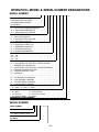
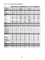
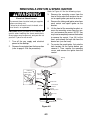
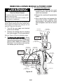
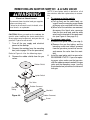
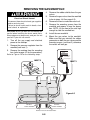
WHIRLPOOL & KITCHENAID
BUILT-IN GAS COOKTOPS
JOB AID
Part No. 4317256
FORWARD
This Job Aid, “Built-In Gas Cooktops,” (Part No. 4317256), provides the technician with information on the installation, operation, and service of KitchenAid & Whirlpool Built-In Gas Cooktops. It
is to be used as a training Job Aid and Service Manual. For specific information on the model
being serviced, refer to the “Use and Care Guide,” or “Tech Sheet” provided with the cooktop.
The Wiring Diagrams and Strip Circuits used in this Job Aid are typical and should be used for
training purposes only. Always use the Wiring Diagram supplied with the product when servicing
the unit.
GOALS AND OBJECTIVES
The goal of this Job Aid is to provide detailed information that will enable the service technician to
properly diagnose malfunctions and repair Built-In Gas Cooktops.
The objectives of this Job Aid are to:
•
•
•
•
Understand and follow proper safety precautions.
Successfully troubleshoot and diagnose malfunctions.
Successfully perform necessary repairs.
Successfully return the cooktop to proper operational status.
WHIRLPOOL CORPORATION assumes no responsibility for any repair
made on our products by anyone other than Authorized Factory Service
Technicians.
Copyright 1999, Whirlpool Corporation, Benton Harbor, MI 49022
- ii -
Table of Contents
PAGE
SPECIFICATIONS .................................................................................................................. 1-1
INSTALLATION HIGHLIGHTS ................................................................................................ 2-1
Gas Supply Requirements ................................................................................................. 2-1
Electrical Requirements ..................................................................................................... 2-3
Installation .......................................................................................................................... 2-4
Converting The Cooktop For Use With L.P. Gas ............................................................... 2-6
PRODUCT OPERATION ........................................................................................................ 3-1
Electronic Ignition System ................................................................................................. 3-1
COMPONENT ACCESS ......................................................................................................... 4-1
Component Locations ........................................................................................................ 4-1
Removing The Maintop ...................................................................................................... 4-2
Removing A Venturi & Spark Ignitor .................................................................................. 4-3
Removing A Spark Module & Power Cord ......................................................................... 4-4
Removing An Ignitor Switch & A Gas Valve ...................................................................... 4-5
Removing The Gas Manifold ............................................................................................. 4-6
COMPONENT TESTING ........................................................................................................ 5-1
The Ignitor Switches .......................................................................................................... 5-1
DIAGNOSIS & TROUBLESHOOTING .................................................................................... 6-1
WIRING DIAGRAMS & STRIP CIRCUITS .............................................................................. 7-1
TECH TIPS ............................................................................................................................. 8-1
Surface Burners & Grates .................................................................................................. 8-1
Cleaning The Surface Burners .......................................................................................... 8-2
Requesting Assistance Or Service .................................................................................... 8-3
KitchenAid Gas Cooktop Warranty .................................................................................... 8-4
Whirlpool Gas Cooktop Warranty ...................................................................................... 8-5
- iii -
KITCHENAID MODEL & SERIAL NUMBER DESIGNATIONS
MODEL NUMBER
K
G
C
S
12
7
G
BL
MODEL NUMBER
INTERNATIONAL SALES IND.
OR MARKETING CHANNEL
IF PRESENT
K=KITCHENAID BRAND
PRODUCT IDENTIFICATION:
EC=ELECTRIC COOKTOPS
GC=GAS COOKTOPS
MERCHANDISING SCHEME
C=CERAMIC GLASS
D=DOWNDRAFT VENT
G=GRILL/GRIDDLE
M=MODULAR DOWNDRAFT
N=INTERNATIONAL COLLECTION
P=PROFESSIONAL/COMMERCIAL
S=STANDARD/PORCELAIN METAL
T=TEMPERED GLASS
X=208 VOLT
E=ELECTRONICS
CAPACITY/SIZE /SERIES/CONFIG
1ST POSITION
1=STANDARD
2=GRILL GRIDDLE
3=TEMPERED GLASS
4=COMMERCIAL
5=CERAMIC GLASS
8=MODULAR/DOWNDRAFT
0=2 BURNER/ELEMENT SYSTEM
2ND POSITION
0=30" WIDE
3=33" WIDE
6=36" WIDE
2=42" OR 12" WIDE
5=15" WIDE
FEATURES
0=STANDARD ELEMENTS/BURNERS
1=RADIANT ELEMENTS
2=DUAL ELEMENTS
3=
4=
5=SEALED BURNERS/CAST ELEMENTS
6=5 BURNERS/ELEMENTS
7=HALOGEN ELEMENTS/6 BURNERS
8=TOUCH CONTROLS
9=INDUCTION
YEAR OF INTRODUCTION
G=1998 H=1999 J=2000
COLOR CODE
AL = Almond
SS = Stainless
BL = Black
WH = White
BT = Biscuit
ENGINEERING CHANGE (NUMERIC)
SERIAL NUMBER
SERIAL NUMBER
X H 07 1 2 3 4 5
OXFORD
YEAR OF INTRODUCTION:
H = 1998, J = 1999, K = 2000
WEEK OF PRODUCTION
(7th WEEK)
PRODUCT SEQUENCE NUMBER
- iv -
0
WHIRLPOOL MODEL & SERIAL NUMBER DESIGNATIONS
MODEL NUMBER
S C S 30 0 4
MODEL NUMBER
INTERNATIONAL SALES IND.
OR MARKETING CHANNEL
IF PRESENT
PRODUCT GROUP:
R = ELECTRIC COOKING PRODUCTS
S = GAS COOKING PRODUCTS
G = WHIRLPOOL GOLD RANGE
PRODUCT IDENTIFICATION:
C = BUILT-IN COOKTOP
J = GOLD ELECTRIC COOKTOP
G = GOLD GAS COOKTOP
CONFIGURATION:
S = PORCELAIN / STEEL TOP
T = TEMPERED GLASS TOP
C = CERAMIC GLASS TOP
M = MODULAR DOWNDRAFT
MODEL SIZE:
20 = 20"
30 = 30"
36 = 36"
FEATURE VARIATIONS:
0 = LOW SPEED COIL ELECTRIC / OPEN-LOW END
BURNER GAS / OPEN BAYS
1 = HIGH SPEED COIL ELECTRIC / SEALED BURNERS
2 = CERAMIC RADIANT ELECTRIC
3 = CERAMIC RADIANT / DUAL
4 = MODULAR
-------------------------------------------0 = NO ELEMENTS / BURNERS
2 = TWO ELEMENT / BURNER
4 = FOUR ELEMENT / BURNER
5 = FIVE ELEMENT / BURNER
YEAR OF INTRODUCTION
G = 1998 H = 1999 J = 2000
COLOR CODE
B = Black
S = Stainless Steel
N = Almond
Z = Almond on Almond
Q = White on White
W = White
ENGINEERING CHANGE (NUMERIC)
SERIAL NUMBER
SERIAL NUMBER
X H 07 1 2 3 4 5
OXFORD
YEAR OF INTRODUCTION:
H = 1998, J = 1999, K = 2000
WEEK OF PRODUCTION
(7th WEEK)
PRODUCT SEQUENCE NUMBER
-v-
G
Q
----
MODEL & SERIAL NUMBER LOCATION
The Model/Serial Number label is located on the underside of the cooktop burner box at the
location shown below.
Model & Serial Number
- vi -
IMPORTANT SAFETY INFORMATION
Your safety and the safety of others is very important.
Important safety messages have been provided in this Job Aid. Always read and obey all safety
messages.
This is the safety alert symbol.
This symbol alerts you to hazards that can kill or hurt you and others.
All safety messages will be preceded by the safety alert symbol and the word
“WARNING.”
All safety messages will identify the hazard, tell you how to reduce the chance of injury, and tell
you what can happen if the instructions are not followed.
WARNING: If the information in this Job Aid is not followed exactly, a fire or explosion may
result causing property damage, personal injury, or death.
Do not store or use gasoline or other flammable vapors and liquids in the vicinity of this or any
other appliance.
WHAT TO DO IF YOU SMELL GAS
•
•
•
•
Do not try to light any appliance.
Do not touch any electrical switch.
Do not use any phone in your building.
Immediately call your gas supplier from a neighbor’s phone. Follow the gas supplier’s
instructions.
• If you cannot reach your gas supplier, call the fire department.
Installation and service must be performed by a qualified installer, service agency or the gas
supplier.
- vii -
— NOTES —
- viii -
SPECIFICATIONS
KITCHENAID MODEL GAS COOKTOPS
KGCT055 & KGCR055G
KGCT365G
KGCS105G, KGCT305G & YKGCT305G
KGCS166G, KGCT366G & YKGCT366G
KGCS127G
1-1
WHIRLPOOL MODEL GAS COOKTOPS
SCS3004G, SCS3014G, SCS3614G,
GLT3014G, & GLT3614G
1-2
30", 36", & 42" GAS PORCELAIN & METAL COOKTOPS
KITCHENAID
SIZE
MODEL NUMBER
Colors Available
WHIRLPOOL
30"
KGCS105G
36"
KGCS166G
42"
KGCS127G
30"
SCS3004G
30"
SCS3014G
36"
SCS3614G
BL/WH/AL/SS/BT
BL/WH/AL/SS/BT
BL/WH/AL/SS/BT
W/N/S
B/Q/Z/S
B/Q/Z/S
Yes -4
Yes - 4
Lite Position
Yes -5
Yes - 5
Lite Position
Yes -6
Yes -6
Lite Position
Yes -4
Yes - 4
Lite Position
Yes -4
Yes - 4
Lite Position
Yes -4
Yes - 4
Lite Position
Yes-4
6,000 Btu Nat
6,000 Btu LP
14,000 Btu Nat
13,000 Btu LP
12,500 Btu Nat
11, 000 Btu LP
NA
NA
NA
NA
NA
NA
9,000 Btu nat
9,000 Btu LP
Cast Iron
No
Yes-5
6,000 Btu Nat
6,000 Btu LP
14,000 Btu Nat
13,000 Btu LP
12,500 Btu Nat
11, 000 Btu LP
NA
NA
9,000 Btu nat
9,000 Btu LP
NA
NA
6,000 Btu nat
6,000 Btu LP
Cast Iron
No
Yes-6
6,000 Btu Nat
6,000 Btu LP
14,000 Btu Nat
13,000 Btu LP
12,500 Btu Nat
11, 000 Btu LP
9,000 Btu Nat
9,000 Btu LP
NA
NA
6,000 Btu nat
6,000 Btu LP
9,000 Btu nat
9,000 Btu LP
Cast Iron
No
Yes - 4
6,000 Btu Nat
6,000 Btu LP
9,000 Btu Nat
9,000btu LP
9,000 Btu Nat
9,000btu LP
NA
NA
NA
NA
NA
NA
9,000 Btu nat
9,000btu LP
Square-Stamped
No
Yes
6,000 Btu Nat
6,000 Btu LP
12,500 Btu Nat
11,000 Btu LP
9,000 Btu Nat
9,000btu LP
NA
NA
NA
NA
NA
NA
9,000 Btu nat
9,000btu LP
Square-Cast Iron
Yes
Yes
6,000 Btu Nat
6,000 Btu LP
12,500 Btu Nat
11,000 Btu LP
9,000 Btu Nat
9,000btu LP
NA
NA
NA
NA
NA
NA
9,000 Btu Nat
9,000btu LP
Square-Cast Iron
Yes
Yes
No
Yes
No
Yes
No
Yes
No
Yes
No
Yes
No
30"
31 3/8"
21"
3 3/8"
36"
37 1/2"
21"
3 3/8"
42"
43 1/2"
21"
3 3/8"
30"
31 3/8"
21"
3 3/8"
30"
31 3/8"
21"
3 3/8"
36"
37 1/2"
21"
3 3/8"
29"
19"
2 7/8"
Yes
35 1/4"
19"
2 7/8"
Yes
40 1/2"
19"
2 7/8"
Yes
29"
19"
2 7/8"
Yes
29"
19"
2 7/8"
Yes
35 1/4"
19"
2 7/8"
Yes
120 Volts,
Single Phase,
60 Hz
15 Amp
NA
3 1/2 Foot,
3 Wire
AGA/CGA
38 lbs.
Yes
Yes
In Use & Care
Yes
Burners
120 Volts,
Single Phase,
60 Hz
15 Amp
NA
3 1/2 Foot,
3 Wire
AGA/CGA
42 lbs.
Yes
Yes
In Use & Care
Yes
Burners
120 Volts,
Single Phase,
60 Hz
15 Amp
NA
3 1/2 Foot,
3 Wire
AGA/CGA
45 lbs.
Yes
Yes
In Use & Care
Yes
Burners
120 Volts,
Single Phase,
60 Hz
15 Amp
NA
3 1/2 Foot,
3 Wire
AGA
35 lbs.
Yes
Yes
In Use & Care
Yes
No
120 Volts,
Single Phase,
60 Hz
15 Amp
NA
3 1/2 Foot,
3 Wire
AGA/CGA
35 lbs.
Yes
Yes
In Use & Care
Yes
No
120 Volts,
Single Phase,
60 Hz
15 Amp
NA
3 1/2 Foot,
3 Wire
AGA
39 lbs.
Yes
Yes
In Use & Care
Yes
No
Included
Included
Included
Included
Included
Included
3191828
3191827
3191828
3191827
3191828
3191827
3191829
3191827
3191829
3191827
3191829
3191827
Controls
Push-To-Turn
Infinite
Ignition System
Burners
Sealed
Right Front
Left Front
Right Rear
Center Right Rear
Center Rear
Center Left Rear
Left Rear
Grates
Bezel
a
Surface
Porcelain/Metal
Lift -up Top
Dimensions
Overall
Width (Side to Side)
Front
Middle
Depth (Front to Back)
Height (Top to Bottom)
Cutout
Width (Side to Side)
Depth (Front to Back)
Height (Top to Bottom)
Mounting Hardware
Other Specifications
Electrical
Circuit
Total Conected Load
Power Cord/Conduit
Agency Approvals
Approximate Net Weight
Approval Over Built-in Ovens
Approval With Downdraft
Warranty
1 Year Full
5 Year Limited
Accessories
LP Gas Conversion Kit
Literature
Use & Care Guide
Installation Instructions
1-3
15", 30", & 36" GAS GLASS COOKTOPS
1-4
INSTALLATION HIGHLIGHTS
GAS SUPPLY REQUIREMENTS
2.
WARNING
3.
Explosion Hazard
Use a new AGA approved gas supply
line.
Install a shutoff valve.
Securely tighten all gas connections.
If connected to LP gas, have a qualified
person make sure gas pressure does
not exceed 14" water column.
Examples of a qualified person includes licensed heating personnel, authorized gas company personnel, and
authorized service personnel.
Failure to do so can result in death, explosion, or fire.
4.
Observe all governing codes and ordinances.
5.
Important: The cooktop must be connected
to a regulated gas supply.
1.
This installation must conform with local
codes and ordinances. In the absence of
local codes, installations must conform
with American National Standard, National
Fuel Gas Code ANSI Z223.1— latest edition*** or CANI — B149.1 or 2**.
**Canadian Standard Association
178 Rexdale Boulevard
Etobicoke, Ontario M9W 1R3
***American Gas Association
1515 Wilson Boulevard
Arlington, Virginia 22209
Input ratings shown on the model/serial
rating plate are for elevations up to 2,000
feet (610 m). For elevations above 2,000
feet (610 m), ratings are reduced at a rate
of 4% for each 1,000 feet (305 m) above
sea level.
The cooktop is equipped for use with
NATURAL gas. It is design-certified by the
American Gas Association for NATURAL
and L.P. gases with the appropriate conversion. The model/serial rating plate, located on the underside of the burner box,
has information on the type of gas that can
be used. If this information does not agree
with the type of gas available, check with
the local gas supplier. See Page 2-6 for
L.P. gas conversion instructions.
Provide a gas supply line of 3/4" rigid pipe
to the cooktop location. A smaller size pipe
on long runs may result in insufficient gas
supply. Pipe-joint compounds, suitable for
use with L.P. gas, must be used. With L.P
gas, piping or tubing size can be a minimum of 1/2". L.P. gas suppliers usually
determine the size and materials used on
the system.
If local codes permit, a new A.G.A. designcertified, 4-5 foot (1.2-1.5 m) long, 1/2" or
3/4" I.D., flexible metal appliance connector is recommended for connecting this
cooktop to the gas supply line. Do not kink
or damage the flexible connector when
moving the cooktop. The pressure regulator has 3/8" female pipe threads. You will
need to determine the fittings required,
depending on the size of your gas supply
line, flexible metal connector and shutoff
valve.
Flexible Gas Supply Line
2-1
6.
The supply line shall be equipped with an
approved shutoff valve. This valve should
be located in the same room as the cooktop
and should be in a location that allows
ease of opening and closing. Do not block
access to the shutoff valve. The valve is
for turning on or shutting off gas to the
appliance.
8.
NATURAL GAS
Set pressure: 4 inches (10.2 cm).
Supply pressure: 7-14 inches (17.8 cm to 35.5
cm) maximum.
Shutoff Valve
(open)
To Cooktop
L.P. GAS
Minimum pressure: 10 inches (25.4 cm).
Supply pressure: 14 inches (35.5 cm).
Gas Supply
Line
7.
The regulator must be checked at a minimum 1-inch (2.5 cm) water column above
the set pressure. The inlet pressure to the
regulator should be as follows for operation and checking the regulator setting:
9.
If rigid pipe is used as a gas supply line, a
combination of pipe fittings must be used
to obtain an in-line connection to the
cooktop. All strains must be removed from
the supply and fuel lines so cooktop will be
level and in line.
Rigid Pipe
2-2
Line Pressure Testing:
Testing Above 1/2 psi (3.5 kPa)
(14 inches (35.6 cm)) W.C. (gauge)
The cooktop and its individual shutoff valve
must be disconnected from the gas supply
piping system during any pressure testing
of that system at test pressures greater
than 1/2 psig (3.5kPa).
Testing Below 1/2 psi (3.5 kPa) (14
inches (35.6 cm)) W.C. (gauge), Or
Lower
The cooktop must be isolated from the gas
supply piping system by closing its individual manual shutoff valve during any
pressure testing of the gas supply piping
system at test pressures equal to or less
than 1/2 psig (3 5 kPa).
ELECTRICAL REQUIREMENTS
Recommended Ground Method
WARNING
For your personal safety, this cooktop must be
grounded. This cooktop is equipped with a 3prong ground plug. To minimize possible shock
hazard, the cord must be plugged into a mating 3-prong ground-type outlet, grounded in
accordance with the National Electrical Code
ANSI/NFPA 70 latest edition*, or Canadian
Electrical Code (CSA) A**, and local codes and
ordinances. If a mating outlet is not available,
it is the personal responsibility, and the obligation of the customer, to have a properly
grounded, 3-prong outlet installed by a qualified electrician.
Electrical Shock Hazard
Plug into a grounded 3-prong outlet.
Do not remove ground prong.
Do not use an adapter.
Failure to follow these instructions can
result in death, fire, or electrical shock.
3-Prong
Ground-Type
Outlet
If codes permit and a separate ground wire
is used, it is recommended that a qualified
electrician determine that the ground path
is adequate.
3-Prong
Ground Plug
Check with a qualified electrician if you are
not sure whether the cooktop is properly
grounded.
Ground
Prong
Do not ground to a gas pipe.
A 120-volt, 60-Hz, AC-only, 15-ampere, fused
electrical supply is required. A time-delay fuse
or circuit breaker is recommended. It is recommended that a separate circuit serving only
this appliance be provided.
Electronic ignition systems operate within wide
voltage limits, but proper ground and polarity
are necessary. In addition to checking that the
outlet provides 120-volt power, and is correctly
grounded, the outlet must be checked by a
qualified electrician to see if it is wired with the
correct polarity. Wiring diagrams are provided
in Section 7 of this Job Aid.
This appliance, when installed, must be electrically grounded in accordance with local
codes, or, in the absence of local codes, with
the current CSA standard C22.1. Canadian
Electrical Code Part 1.
Copies of the standards listed above may be
obtained from:
*National Fire Protection Association
Batterymarch Park
Quincy, Massachusetts 02269
**Canadian Standard Association
178 Rexdale Boulevard
Etobicoke, Ontario M9W 1R3
2-3
INSTALLATION
1.
5.
Glass Cooktops Only: Remove the foam
strip from the literature package and apply
the strip around the bottom edge of the
glass maintop so it is flush with the edges.
Burner Box
Install the 2-1/2" (6.4 cm) clamping screws
into the brackets and tighten them so that
they are firmly against the underside of the
countertop. DO NOT overtighten the
screws.
Burner Box
Glass Maintop
Countertop
Foam Strip
2-1/2" (6.4 cm)
Clamping Screw
Glass Maintop
2.
Remove the two screws from the left and
right bottom edges of the burner box, then
place the brackets on top of the box.
Position the brackets as shown and handtighten one screw into each bracket.
Bracket
Screws
6.
Bracket
Install the pressure regulator with the arrow on the regulator pointing up toward
the burner box so you can reach the access cap.
Rear of
Cooktop
Front of
Cooktop
3.
4.
Bracket
Install the cooktop into the countertop
opening so that the front edge of the
cooktop glass is parallel with the front
edge of the countertop. NOTE: To prevent
scratching the countertop, lift the entire
cooktop to make any position adjustments.
Rotate the brackets away from the burner
box and install a second screw into each
bracket, then securely tighten the bracket
screws to the burner box (see the illustration in step 5).
Pressure
Regulator
Gas Flow Arrow
Pointing Up
Access
Cap
2-4
IMPORTANT: In the next step, you will need
to:
7.
• Determine the fittings that are required
to hook up the gas supply to the pressure regulator.
• Make sure that all of the connections
are wrench-tightened and are not overtightened (you could crack the regulator and cause a gas leak). Do not allow
the regulator to turn on the pipe when
you tighten the fittings.
• Use pipe-joint compound that is made
for use with Natural and L.P. gas.
Assemble the flexible metal connector from
the gas supply pipe to the pressure regulator. NOTE: Make sure that you do not
kink the flexible metal connector.
Adapter
Flexible Metal
Nipple
Connector
3/8" Nipple
3/8" Adapter
Manual Shutoff
Valve
8.
Use Pipe-Joint
Compound
Pressure
Regulator
Open the manual gas shutoff valve and
wait a few minutes for the gas to flow
through the lines.
Shutoff Valve
(open)
To Cooktop
Gas Supply
Line
2-5
CONVERTING THE COOKTOP FOR USE WITH L.P. GAS
NOTE: Refer to Conversion Kit #3192261 for
SCS, GLT, KGCT, KGCS Model Series L.P. Gas
Conversion Instructions.
Parts provided with this Conversion Kit:
• Orifice/Spud Package - #3192198
• Conversion Instructions - #3192260
• Conversion Label - #3192259
Gas conversions from Natural gas to L.P.
gas must be done by a qualified installer.
Caution; Before proceeding with conversion, shut off the gas supply to the appliance prior to disconnecting the electrical
power.
2.
Rear of
Cooktop
Pressure
Regulator
Gas Flow Arrow
Pointing Up
WARNING
Access
Cap
This Conversion Kit shall be installed
by a qualified service agency in accordance with the manufacturer’s instructions and all applicable codes and requirements of the authority having jurisdiction. If the information in these
instructions is not followed exactly, a
fire, explosion or production of carbon
monoxide may result causing property
damage, personal injury or loss of life.
The qualified service agency is responsible for the proper installation of this
kit. The installation is not proper and
complete until the operation of the converted appliance is checked as specified in the manufacturer’s instructions
supplied with this kit.
1.
Remove access cap by using a screwdriver or quarter, turning the access cap
counterclockwise.
The gas pressure regulator has two settings which are stamped on either side of
the cap. Turn the cap over and reinstall it
into the regulator with the stamp “LP”
visible from the outside of the regulator.
LP
Position of cap for a
correctly converted
regulator
The regulator must be checked at a minimum of 1-inch (2.5 cm) water column
above the set pressure. The inlet pressure
to the regulator should be as shown on the
next page for operation and checking the
regulator setting.
Check that main gas supply line to the
cooktop has been shut off and the power
supply cord is disconnected.
Shutoff Valve
(closed)
To Cooktop
Gas Supply
Line
2-6
L.P. GAS
3.
Minimum pressure: 10 inches (25.4 cm).
Supply pressure: 14 inches (35.5 cm).
Testing below 1/2 psi (3.5 kPa) 14 inches
(35.6 cm) W.C. (gauge) or lower
The cooktop must be isolated from the gas
supply piping system by closing its individual
manual shutoff valve during any pressure testing of the gas supply piping system at test pressures equal to or less than l/2 psig (3.5 kPa).
4.
Remove burner cap. Remove two screws
in the burner base and remove burner
base. IMPORTANT: REMOVE ONE
BURNER BASE AT A TIME, THEN CONVERT AND REPLACE IT. DO NOT DISASSEMBLE THE ENTIRE COOKTOP.
Refer to the following Orifice Chart and
match the correct color orifice with the
burner location and model that is being
converted.
Rating
Color
Size
6,000 BTU
Black
78
9,000 BTU
Brass
95
11,000 BTU
Blue
110
13,000 BTU
Green
115
Orifice Size Stamp
ORIFICE CHART
Right
Front
Right
Rear
Left
Front
Left
Rear
SCS3004
Black
Brass
Brass
Brass
SCS3014, SCS3614
GLT3014, GLT3614
Black
Brass
Blue
Brass
KGCTDSS
Blue
Black
KGCT305, KGCS105,
KGCT365
Black
Blue
Green
Brass
KGCT366, KGCS166
Black
Blue
Green
Black
KGCS127
Black
Blue
Green
Brass
Models
Left
Rear
Center
Left
Left
Front
Center
Right
Right
Rear
Left
Rear
Right
Front
2-7
Center
Center
Left
Center
Right
Black
Brass
Brass
Center
Left
Front
Right
Rear
Right
Front
5.
6.
Electronic Ignition System—
Initial Lighting
Use a nut driver (7 mm) to remove the
existing orifice and replace it with an LP
orifice. Note: A small amount of tape inside the nut driver will help hold the orifice
in the nut driver.
Replace burner base and tighten the two
screws.
Cooktop burners use electronic ignitors in place
of standing pilots. When the cooktop control
knob is pushed in and turned to the "LITE" position, the system creates a spark to light the
burner. This sparking continues until the control knob is turned to the desired setting.
IMPORTANT: The ignitor electrode is ceramic and could break during conversion.
Be sure that the electrode comes through
the hole in the burner base while you tighten
the screws.
Cap
Ignitor Electrode
9.
Burner Base
7.
Complete steps 4, 5, and 6 for each burner
on the cooktop.
8.
Use the following procedure and leak test
the cooktop:
WARNING: NEVER TEST FOR GAS
LEAKS WITH A MATCH OR OTHER
FLAME.
Use a brush and apply liquid detergent to
all of the gas connections and check them
for leaks. Bubbles around connections will
indicate a leak. If a leak appears, shut off
gas valve controls, tighten the connection,
and recheck the connection again. Clean
all of the detergent solution from the
cooktop.
2-8
Check the operation of the cooktop burners. Push in and turn each control knob to
the “LITE” position. The flame should light
within 4-seconds. Do not leave the knob
in the “LITE” position after burner lights.
If the burners do not light properly, turn the
control knob to the “OFF” position. Check
that the burner cap is in the proper position. Check that the power supply cord is
plugged in and that the circuit breaker, or
house fuse, has not blown. Check that the
gas shutoff valve is in the “ON” position.
Check the operation again. If a burner still
does not light, refer to “Diagnosis &
Troubleshooting” in Section 6.
decreased by turning the screw. Adjust
the flame until you can quickly turn the
knob from “LITE” to the lowest position
without extinguishing the flame. The flame
should be as small as possible without
going out.
10. Push in and turn each control knob from
the “LITE” to the “LO” setting. The low
flame should be at a minimum steady blue
flame.
If flame needs to be adjusted, turn the
control to the “LO” setting, and remove the
control knob. Insert a small flat-blade
screwdriver into the valve stem. Turn the
adjustment screw to obtain the smallest
flame that will not go out when the control
of a cold burner is quickly turned from “Hl”
to “LO.” Turn the adjustment screw clockwise to decrease the flame, and counterclockwise to increase it. Repeat for other
cooktop burners, as needed.
12. Check the flame at the “Hl” setting for a
blue color, and a clean, soft shape. There
should be no yellow tips on the flames, or
any blowing or lifting off the burner head.
An occasional orange flash is normal, and
reflects different elements in the air or gas.
Ports
Typical Burner
Flame At Highest
Setting
Valve Stem
Adjustment Screw
13. Completely fill out the Conversion Label (#
3192259), and attach the label to the bottom of the cooktop beside the rating tag.
Do not cover the rating tag with the label.
THE OPERATING MANIFOLD PRESSURE IS 10 INCHES W.C.
THE INPUT RAGING FOR EACH MAIN BURNER FOR EACH MODEL
IS LISTED ON THE RATING LABEL.
THIS APPLIANCE WAS CONVERTED ON
DAY-MONTH-YEAR
TO LP GAS WITH KIT NO. 3192261
BY ORGANIZATION:
ADDRESS:
, WHICH ACCEPTS THE
RESPONSIBILITY THAT THIS CONVERSION HAS BEEN PROPERLY MADE.
3192259 REV. A
THIS APPLIANCE HAS BEEN CONVERTED FOR USE WITH L.P.
11 . Push in and turn each control knob to the
“LO” (or simmer) setting. This setting has
been factory-set for each control and is the
lowest setting available that will provide
reliable reignition of the burner. If it does
not stay lit on the “LO” setting, check the
setting as follows:
a) Turn control to "LITE" until burner ignites.
b) Quickly turn the knob down to its lowest position.
c) If the burner goes out, readjust the valve
as follows:
Remove the surface burner control knob.
Insert a flat-blade screwdriver into the
hollow valve stem and engage the slotted
screw. Flame size can be increased or
14. For higher altitudes, no further adjustments are necessary. Derating the burners is also unnecessary.
15. Save the orifices removed from the
cooktop, along with the instructions, for
possible future use.
NOTE: To convert the cooktop back to use with
Natural gas, start on Page 2-6, and convert
the regulator, and replace the orifices in the
order in which they were removed.
2-9
— NOTES —
2-10
PRODUCT OPERATION
ELECTRONIC IGNITION SYSTEM
Refer to Figure 3-1 for the following sequence.
SEALED BURNER
When a main burner control knob q is turned to the “lite” position, the gas valve r opens, and
gas flows through the pressure regulator s into the manifold t through the open valve. As gas
passes through the valve and its orifice, it is directed into the venturi u, where it mixes with
primary air to create the proper mixture necessary for combustion.
At the same time, line voltage is applied through the ignitor switch v, to the spark module w,
which produces high-voltage, low amperage pulses to all of the spark ignitors x. The pulses
cause a spark y to occur between the spark ignitor electrode, and the grounded burner cap z.
The gas and air mixture at the burner is ignited by the spark, and a flame is produced at each
of the top burner ports.
SPARK
MODULE
7
120 VAC
LINE VOLTAGE
HIGH VOLTAGE
LOW AMPERAGE
PULSES
BURNER CAP
10
TO SPARK
IGNITOR
9
SPARK
SPARK
IGNITOR
8
BURNER
BURNER FLAME
IGNITOR SWITCH
PRESSURE
REGULATOR
W
GAS
FLO
4
3
GAS
6
2
GAS
MANIFOLD
FLOW
5
GAS VALVE
AIR SHUTTER
OFF
TE
GAS INLET
1
BURNER
CONTROL
KNOB
3-1
VENTURI
Figure 3-1
LI
— NOTES —
3-2
COMPONENT ACCESS
COMPONENT LOCATIONS
This section instructs you on how to service
each component inside the built-in cooktops.
The components and their locations are shown
below.
NOTE: The KitchenAid Model KGCS166G/
KGCT366G cooktop is shown below, however,
the other built-in cooktop components are identical, and are serviced in the same manner.
Burner Screw (2)
Burner Base
Drip Pan
Maintop
Control Knob
Bezel
Left Rear
Venturi &
Spark Ignitor
Left Front
Venturi &
Spark Ignitor
Spark Module
Center
Venturi &
Spark Ignitor
Manifold
Left Front
Center
Right Rear
Gas Control
Gas Control
Gas Control
& Ignitor Switch & Ignitor Switch & Ignitor Switch
Right Rear
Venturi &
Spark Ignitor
Right Front
Venturi &
Spark Ignitor
Right Rear
Gas Control
& Ignitor Switch
Left Rear
Gas Control
& Ignitor Switch
4-1
REMOVING THE MAINTOP
1.
WARNING
Turn off the gas supply and electrical
power to the cooktop.
Remove the grates and burner caps.
2.
Electrical Shock Hazard
Refer to Figure 4-1 for the following steps.
Disconnect from electrical and gas supplies
before servicing unit.
3.
4.
Failure to do so could result in death, electrical shock, or explosion.
CAUTION: When you work on the cooktop, be
careful when handling the sheet metal parts.
Sharp edges may be present, and you can cut
yourself if you are not careful.
Remove the knobs from the controls.
Remove all of the burner bases. To remove a burner base, remove the two
screws, and lift it off the drip pan.
Lift the maintop off the countertop. NOTE:
If you are replacing the maintop, unclip the
control bezels from the mounting holes,
otherwise leave them installed.
5.
Burner Screw (2)
Burner Base
Drip Pan
Maintop
Control Knob
Bezel
Figure 4-1
4-2
REMOVING A VENTURI & SPARK IGNITOR
Refer to Figure 4-2 for the following steps.
WARNING
3.
Remove the mounting screw from the
front of the bracket that contains the venturi or spark ignitor you wish to service.
Remove the tubing and ignitor wires from
each venturi and spark ignitor on the
bracket.
Lift the front of the mounting bracket, remove the mounting screw from the venturi, and remove the venturi. NOTE: You
may have to completely remove the bracket
to remove the venturi. If so, lift it at the
front, and unhook the back tab from the
burner box (see the inset).
Electrical Shock Hazard
Disconnect from electrical and gas supplies
before servicing unit.
4.
Failure to do so could result in death, electrical shock, or explosion.
5.
CAUTION: When you work on the cooktop, be
careful when handling the sheet metal parts.
Sharp edges may be present, and you can cut
yourself if you are not careful.
1.
2.
Turn off the gas supply and electrical
power to the cooktop.
Remove the maintop from the burner box
(refer to page 4-2 for the procedure).
6.
To service the spark ignitor, first note the
hole location for the ignitor before you
remove it. Then, remove the mounting
screw, and remove the ignitor from the
venturi.
Maintop
Lift Bracket
Unhook At Back
Of Burner Box
Gas Line
Tubing
Venturi
Bracket
Spark Ignitor
Ignitor Screw
Burner Box
INSET
Insert Venturi
Pin Here
Bracket
Ignitor Wire
Venturi
Mounting Screw
See Inset
Front Of
Burner Box
Bracket Screw
Figure 4-2
4-3
REMOVING A SPARK MODULE & POWER CORD
4.
WARNING
Electrical Shock Hazard
Disconnect from electrical and gas supplies
before servicing unit.
Failure to do so could result in death, electrical shock, or explosion.
CAUTION: When you work on the cooktop, be
careful when handling the sheet metal parts.
Sharp edges may be present, and you can cut
yourself if you are not careful.
1.
2.
To remove the power cord:
a) Disconnect the lead from the spark
module terminal, and from the ignitor
switch wire connector.
b) Remove the screw from the ground wire
eyelet.
c) Use a pair of pliers and squeeze the
strain relief sections together while
pressing down, and remove the strain
relief and power cord from the burner
box.
Turn off the gas supply and electrical
power to the cooktop.
Remove the maintop from the mounting
box (refer to page 4-2 for the procedure).
Brown Wires
(to Spark Ignitors)
Yellow Wires
(to Spark Ignitors)
Hex-Head Screw
Refer to Figure 4-3 for the following steps.
3.
Spark Module
For 30" Model
Cooktops
To remove the spark module, disconnect the wires from the terminals and
remove the mountng screw(s). NOTE: Both
types of spark module are shown in the
illustration. Use whichever one matches
the cooktop you are servicing.
White Wire
(from Ignitor Switch)
Brown Wires
(to Spark Ignitors)
Yellow Wires
(to Spark Ignitors)
Spark Module
For 36" & 45"
Model Cooktops
Ignitor Switch
Wire Connector
Hex-Head
Screw (3)
Strain
Relief
Black Wire
(from Ignitor Switch)
Power
Cord
White Wire
(from Ignitor Switch)
Green
Ground Wire
Ground Wire
Figure 4-3
4-4
REMOVING AN IGNITOR SWITCH & A GAS VALVE
NOTE: If one ignitor switch is defective, all of
the switches must be replaced as an assembly.
WARNING
4.
Electrical Shock Hazard
Disconnect from electrical and gas supplies
before servicing unit.
Failure to do so could result in death, electrical shock, or explosion.
CAUTION: When you work on the cooktop, be
careful when handling the sheet metal parts.
Sharp edges may be present, and you can cut
yourself if you are not careful.
1.
2.
5.
Turn off the gas supply and electrical
power to the cooktop.
Remove the maintop from the mounting
box (refer to page 4-2 for the procedure).
Refer to Figure 4-4 for the following steps.
3.
6.
Remove the rubber shields from the gas
valves.
Rubber Shield
To remove an ignitor switch:
a) Pull up firmly on the switch body, unsnap it from the mounting screw heads
of the gas valve, and slide it off the stem.
b) When all of the switches are removed,
disconnect the black wire connector
from the line cord lead, and the white
wire from the terminal of the spark module (see Figure 4-3 on page 4-4).
To remove a gas valve:
a) Remove the ignitor switch (see step 4).
b) Remove the gas line tubing, and the
mounting screw and rubber grommet
from the gas valve you wish to service,
and remove the valve from the manifold.
Install the new ignitor switch or gas valve.
REASSEMBLY NOTE: If you are replacing a gas valve, make sure that you reinstall the rubber grommets on both the gas
valve and the mounting screw, (see the
illustration below), otherwise the valve will
leak gas.
Ignitor Switch
Gas Valve
Rubber Grommet
Gas Line
Tubing
Figure 4-4
Manifold
Rubber Grommet
Screw
4-5
REMOVING THE GAS MANIFOLD
4.
WARNING
5.
Electrical Shock Hazard
Disconnect from electrical and gas supplies
before servicing unit.
6.
7.
Failure to do so could result in death, electrical shock, or explosion.
CAUTION: When you work on the cooktop, be
careful when handling the sheet metal parts.
Sharp edges may be present, and you can cut
yourself if you are not careful.
1.
2.
3.
8.
9.
Turn off the gas supply and electrical
power to the cooktop.
Remove the pressure regulator from the
manifold (see inset 1).
Remove the maintop from the mounting
box (refer to page 4-2 for the procedure).
Remove the rubber shields from the gas
valves.
Remove the gas valves from the manifold
(refer to steps 4 & 5 on page 4-5).
Remove the front screws from each rail.
Remove the mounting screws from the
manifold and remove it from the burner
box. NOTE: Lift the front of the rails high
enough to slide the manifold out.
Install the new manifold.
Mount the gas valves to the manifold.
Make sure that you reinstall the rubber
grommets on both the gas valves and the
mounting screws, (see inset 2), otherwise
the valves will leak gas.
Burner Box
Manifold
Refer to Figure 4-5 for the following steps.
Unscrew Regulator
From Manifold
Pressure Regulator
INSET 2
Tubing
INSET 1
Screws
Manifold
Gas Valve
Rubber
Grommet
Rubber
Grommet
Screw
Rails
Manifold
Figure 4-5
Screws
Lift rail to
remove manifold
Screws
Lift rail to
remove manifold
Remove 4 Screws To Loosen Rails
4-6
COMPONENT TESTING
THE IGNITOR SWITCHES
Refer to Figure 5-1 on the next page.
3. Disconnect the black ignitor switch wire
from the line cord connector and the white
wire from the spark module terminal.
4. Connect the leads of an ohmmeter to the
ends of the spark module wires.
5. Set the ohmmeter to the R x 1 scale.
6. Press and turn one of the gas valve knobs
to the LITE position. At that point, the
switch should close, and the meter should
indicate continuity.
7. Continue to turn the knob away from the
LITE position. The switch should open,
and the meter should indicate an open
(infinite ∞) circuit.
8. Repeat steps 6 & 7 for all of the other
ignitor switches. If the readings are not as
stated, replace the entire ignitor switch
assembly (they are supplied as an assembly and cannot be changed individually).
WARNING
Electrical Shock Hazard
Disconnect from electrical and gas supplies
before servicing unit.
Failure to do so could result in death, electrical shock, or explosion.
NOTE: The ignitor switches are connected to
each other in a parallel configuration so that if
one switch fails, the others will still operate. To
check each of the ignitor switches for proper
operation, perform the following steps.
1. Remove the maintop from the cooktop
(see page 4-2).
2. Reinstall the knobs back on the valve
stems.
5-1
OFF
OFF
LITE
OFF
Ignitor Switch On
(Closed 0 Ω)
Ignitor Switch Off
(Open ∞)
CONTINUITY
0Ω
Rx10
OPEN
INFINITY ∞
Rx100
Rx1
Rx10
Rx1k
Rx1
Black Ignitor
Switch Wire
Rx100
Rx1k
Power Cord Lead
White Ignitor
Switch Wire
Spark Module
Left Front
Ignitor Switch
Center
Ignitor Switch
Left Rear
Ignitor Switch
Figure 5-1
5-2
Right Front
Ignitor Switch
Right Rear
Ignitor Switch
DIAGNOSIS & TROUBLESHOOTING
PROBLEM
Nothing will operate.
A burner fails to light.
The burner flames are uneven.
The burner flames lift off the
burner ports, are yellowtipped, or are noisy when
turned off.
Cooking does not have the
desired results.
POSSIBLE CAUSE
SOLUTION
• The cooktop is not wired
to a live circuit with the
proper voltage supply.
• The cooktop is not properly connected to the gas
supply.
• A household fuse has
blown, or a circuit breaker
has opened.
• A control knob is not set
correctly.
• Wire the cooktop into a
live circuit with the proper
voltage.
• Properly connect the gas
supply to the cooktop.
• A household fuse has
blown, or a circuit breaker
has opened.
• The burner is wet from
being washed.
• The burner ports are
clogged.
• Replace the household
fuse or reset the circuit
breaker.
• Allow the burner to dry.
• The burner ports are
clogged.
• Clean the burner ports
with a straight pin (see
Section 8).
• Clean the burner (see
Section 8).
• Check the air/gas mixture
(see “Electronic Ignition
System—Initial Lighting”
on page 2-8).
• The burner needs to be
cleaned.
• The air/gas mixture is incorrect.
• The cooktop is not level.
• The pan used is not the
correct type or size.
• The flame size does not fit
the cookware being used.
• The flow of combustion
air and/or ventilation air to
the cooktop is blocked.
6-1
• Replace the household
fuse or reset the circuit
breaker.
• Push in on the control
knobs before turning
them.
• Clean the burner ports
with a straight pin (see
Section 8).
• Level the cooktop.
• Refer to a reliable cookbook for the recommended pan type and
size.
• The pan should be the
same size, or slightly
larger, than the cooking
area being used.
• Remove any obstructions
around the knobs or burners.
— NOTES —
6-2
WIRING DIAGRAMS & STRIP CIRCUITS
WIRING DIAGRAMS
KitchenAid Models KGCR055G & KGCT055G
PLUG
Neutral
5/16" Blade
Line
1/4" Blade
Ground
Round Pin
120 VAC, 60 Hz
1 Phase
15 or 20 Ampere
GRN or GRN/YEL
BLK
Ground
WHT
Connect
.250 Terminals
SPARK
MODULE
WHT
BLK
(NOT USED)
(NOT USED)
YEL
or
BRN
IGNITOR SWITCHES
(ON VALVES)
Electric circuit closed
when knob is rotated
55 to 95 degrees
counterclockwise from OFF
SPARK
IGNITORS
7-1
KitchenAid Models KGCS105G, KGCT305G,
YKGCT305G, & KGCT365G
Whirlpool Models GLT3014G, GLT3614G, SCS3004G,
SCS3014G, & SCS3614G
PLUG
Neutral
5/16" Blade
Line
1/4" Blade
Ground
Round Pin
120 VAC, 60 Hz
1 Phase
15 or 20 Ampere
GRN or GRN/YEL
BLK
Ground
WHT
Connect
.250 Terminals
SPARK
MODULE
WHT
BLK
YEL
or
BRN
IGNITOR SWITCHES
(ON VALVES)
Electric circuit closed
when knob is rotated
55 to 95 degrees
counterclockwise from OFF
SPARK
IGNITORS
7-2
KitchenAid Models KGCS166G, KGCT366G, & YKGCT366G
PLUG
Neutral
5/16" Blade
Line
1/4" Blade
120 VAC, 60 Hz
1 Phase
15 or 20 Ampere
Ground
Round Pin
GRN or GRN/YEL
BLK
Ground
GRN or GRN/YEL
Ground
WHT
Connect
.250 Terminals
WHT
N
1
L1
2
3
GND
BLK
5
4
IGNITOR SWITCHES
(ON VALVES)
Electric circuit closed
when knob is rotated
55 to 95 degrees
counterclockwise from OFF
YEL or
BRN
(5)
SPARK
IGNITORS
7-3
SPARK
MODULE
KitchenAid Model KGCS127G
PLUG
Neutral
5/16" Blade
Line
1/4" Blade
Ground
Round Pin
120 VAC, 60 Hz
1 Phase
15 or 20 Ampere
GRN or GRN/YEL
BLK
Ground
WHT
WHT
Connect
.250 Terminals
BLK
WHT
SPARK
MODULE 1
SPARK
MODULE 2
BLK
IGNITOR SWITCHES
(ON VALVES)
Electric circuit closed
when knob is rotated
55 to 95 degrees
counterclockwise from OFF
YEL or
BRN
(6)
SPARK
IGNITORS
STRIP CIRCUIT
IGNITOR SWITCH (CLOSED)
L1
L2
IGNITOR
SWITCH
SPARK
MODULE
N
SPARK
IGNITOR
7-4
TECH TIPS
SURFACE BURNERS & GRATES
The locator pin on the grates must be positioned in the burner cap hole to hold the grate
in place (see Figure 8-1).
The left and right grates contain grooves. The
grooves must always face inward toward the
control knobs to hold the grates in place. The
middle grate must be placed in position first
followed by the left and right grates (see Figure 8-2).
IMPORTANT: The cooktop has been factoryset for use with Natural gas. An L.P. Conversion Kit is supplied for converting the cooktop
for use with L.P. gas.
The sealed gas burners spread the heat evenly
across the bottom of the cookware and provide infinite heat control.
Locator Pin
Burner Cap
Figure 8-1
Left Grate
Middle Grate
Tab
Groove
Figure 8-2
8-1
CLEANING THE SURFACE BURNERS
Refer to Figure 8-3.
The burner caps should be routinely removed
and cleaned. Keeping the burner caps clean
prevents improper ignition and an uneven
flame.
For the proper flow of gas and ignition of the
burner, DO NOT ALLOW SPILLS, FOOD,
CLEANING AGENTS, OR ANY OTHER MATERIAL TO ENTER THE GAS TUBE (VENTURI) OPENING.
Gas must flow freely through the gas tube
opening for the burner to light properly. You
must keep this area free of any soil and protect it from boilovers or spillovers. Always keep
the burner cap in place whenever a surface
burner is in use.
If the knobs are removed while cleaning, be
careful not to spill liquids through the holes in
the control area. Moisture can cause the ignitor switches to fail.
Occasionally check the burner flames for
proper size and shape, as shown in Figure
8-4. A good flame is blue in color. If the flames
are uneven, you may need to clean the burners.
Flame
Figure 8-4
To clean the burners:
1. Lift the burner caps off the burner base.
2. Clean the burner caps with warm, soapy
water and a sponge. You can also clean the
caps with a mildly abrasive plastic scrubbing pad and powdered cleanser. Do not
clean the burner caps in a dishwasher or
self-cleaning oven.
3. If the gas tube opening has become soiled
or clogged, use a cotton swab or a soft cloth
to clean the area.
4. If the ports are clogged, clean them with a
straight pin (see Figure 8-5). Do not enlarge, or distort the port. Do not use a
wooden toothpick. If the burner needs to be
adjusted, call a qualified technician for service.
Cast-Iron
Burner Cap
Alignment Pins
Spark
Ignitor
Straight Pin
Burner
Base
Figure 8-3
Figure 8-5
5. After cleaning the gas tube opening and
ports, replace the burner caps. To replace
the burner caps, make sure the alignment
pins on the burner base are properly aligned
with the cap.
6. Turn on the burner to see if it will light. If the
burner does not light after you have cleaned
it, contact an authorized KitchenAid or
Whirlpool service technician. Do not service the sealed burner yourself.
Gas Tube (Venturi)
Opening
Allow the cooktop to cool before cleaning it.
Do not use oven cleaners, bleach, or rust removers, or obstruct the flow of combustion and
ventilation air to the burners.
8-2
REQUESTING ASSISTANCE OR SERVICE
Before calling for assistance or service, please
check the “Diagnosis &Troubleshooting” in
Section 6. It may save the cost of a service
call. For further help, follow these instructions.
If you need assistance or service in the
U.S. A.:
Call the KitchenAid Consumer Assistance
Center toll free, at
1-800-422-1230, OR
Call the Whirlpool Consumer Assistance
Center,toll free at:
1-800-253-1301.
If you need assistance or service in Canada:
Call the Inglis Limited Consumer Assistance
Center telephone number toll-free, 8:30 a.m.
to 6:00 p.m. (EST) at:
1-800-461-5681.
Our consultants are available to assist you.
When calling, please have the purchase date,
and the complete model and serial number of
your appliance handy. This information will help
with your request.
Our consultants provide assistance with:
• Features and specifications on our full
line of appliances.
• Installation information.
• Use and maintenance procedures.
• Accessory and repair parts sales.
• Specialized customer assistance
(Spanish & French (Canada) speaking,
hearing impaired, limited vision, etc.).
• Referrals to local dealers, service companies, and repair parts distributors.
KitchenAid and Whirlpool service technicians
are trained to fulfill the product warranty and
provide after-warranty service, anywhere in the
United States. To locate the authorized
KitchenAid or Whirlpool service company in
your area, you can also look in your telephone
directory Yellow Pages.
If you need to order replacement parts, we
recommend that you only use factory authorized parts. These parts will fit right and work
right, because they are made with the same
precision used to build every new KitchenAid
and Whirlpool appliance.
To locate factory authorized replacement parts
in your area, call our Consumer Assistance
Center telephone number or your nearest authorized service center.
If you need further assistance, you can write
to KitchenAid, or Whirlpool, with any questions
or concerns at:
KitchenAid/Whirlpool Brand Home Appliances
Consumer Assistance Center
c/o Correspondence Dept.
2000 North M-63
Benton Harbor, Ml 49022-2692
In Canada, contact:
Consumer Relations Department
Inglis Limited
1901 Minnesota Court
Mississauga, Ontario L5N 3A7
Please include a daytime phone number in your
correspondence.
8-3
KITCHENAID GAS COOKTOP WARRANTY
LENGTH OF
WARRANTY:
KITCHENAID
WILL PAY FOR:
KITCHENAID
WILL NOT PAY FOR:
ONE-YEAR FULL
WARRANTY
FROM DATE OF
PURCHASE.
Replacement parts
and repair labor
costs to correct
defects in materials or workmanship. Service must
be provided by an
authorized
KitchenAid servicing outlet.
SECONDTHROUGH FIFTHYEAR LIMITED
WARRANTY
FROM DATE OF
PURCHASE.
Replacement parts
for any gas burner
to correct defects in
materials or workmanship.
A. Service calls to:
1. Correct the installation of the cooktop.
2. Instruct you how to use the cooktop.
3. Replace house fuses or correct house
wiring.
4. Correct house plumbing.
B. Repairs when cooktop is used in other than
normal home use.
C. Damage resulting from accident, alteration,
misuse, abuse, fire, flood, acts of God, improper installation, or installation not in accordance with local electrical or plumbing codes.
D. Any labor costs during the limited warranties.
E. Replacement parts or repair labor costs for
units operated outside the United States and
Canada.
F. Pickup and delivery. This product is designed
to be repaired in the home.
G. Repairs to parts or systems resulting from unauthorized modifications made to the appliance.
H. In Canada, travel or transportation expenses
for customers who reside in remote areas.
KITCHENAID AND KITCHENAID CANADA DO NOT ASSUME ANY RESPONSIBILITY FOR
INCIDENTAL OR CONSEQUENTIAL DAMAGES. Some states or provinces do not allow the
exclusion or limitation of incidental or consequential damages, so this exclusion or limitation may
not apply to you. This warranty gives specific legal rights and you may also have other rights
which vary from state to state or province to province.
Outside the United States and Canada, a different warranty may apply. For details, please
contact your authorized KitchenAid dealer.
If you need assistance or service, first see the "Troubleshooting" section in this book. After checking "Troubleshooting," additional help can be found by checking the "Requesting Assistance or
Service" section. In the U.S.A., call our Consumer Assistance Center at 1-800-422-1230. In Canada,
call our KitchenAid Consumer Assistance Center at 1-800-461-5681.
8-4
WHIRLPOOL GAS COOKTOP WARRANTY
LENGTH OF
WARRANTY:
WHIRLPOOL
WILL PAY FOR:
WHIRLPOOL
WILL NOT PAY FOR:
ONE-YEAR FULL
WARRANTY
FROM DATE OF
PURCHASE.
FSP® replacement
parts and repair
labor costs to
correct defects in
materials or workmanship. Service
must be provided
by an authorized
Whirlpool service
company.
A. Service calls to:
1. Correct the installation of the cooktop.
2. Instruct you how to use the cooktop.
3. Replace house fuses or correct house
wiring or plumbing.
B. Repairs when the cooktop is used in other
than normal, single-family household use.
C. Pickup and delivery. The cooktop is designed
to be repaired in the home.
D. Damage to the cooktop caused by accident,
alteration, misuse, abuse, fire, flood, acts of
God, or use of products not approved by
Whirlpool.
E. Repairs to parts or systems resulting from unauthorized modifications made to the appliance.
F. In Canada, travel or transportation expenses
for customers who reside in remote areas.
WHIRLPOOL CORPORATION AND INGLIS LIMITED SHALL NOT BE LIABLE FOR INCIDENTAL OR CONSEQUENTIAL DAMAGES. Some states or provinces do not allow the exclusion or limitation of incidental or consequential damages, so this exclusion or limitation may not
apply to you. This warranty gives specific legal rights and you may also have other rights which
vary from state to state or province to province.
Outside the United States and Canada, a different warranty may apply. For details, please
contact your authorized Whirlpool dealer.
If you need service, refer to the “Requesting Assistance or Service” section on page 8-3. After
checking “Requesting Assistance or Service,” additional help can be found by calling the Whirlpool Consumer Assistance Center telephone number, 1-800-253-1301, from anywhere in the
U.S.A. In Canada, contact your authorized Inglis Limited Appliance Service company.
8-5
— NOTES —
8-6