1
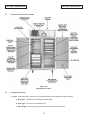
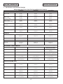
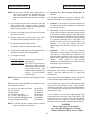
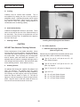
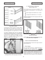
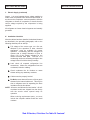
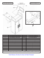
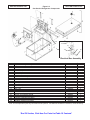
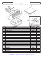
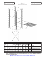
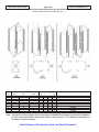
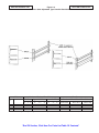
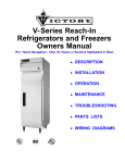
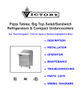
V- Series Reach-In
Refrigerators and Freezers
Owners Manual
(For “Quick Navigation”, Click On Topics or Sections Highlighted In Blue)
! DESCRIPTION
! INSTALLATION
! OPERATION
! MAINTENANCE
! TROUBLESHOOTING
! PARTS LIST
! WIRING DIAGRAMS
LIMITED WARRANTY
(Continental USA Only)
The Seller warrants to the original purchaser, equipment manufactured by Seller to be free from defects in
material and workmanship for which it is responsible. The Seller’s obligation under this warranty shall be
limited to replacing or repairing at Seller’s option, without charge, F.O.B. Sellers factory, any part found to be
defective and any labor and material expense incurred by Seller in repairing or replacing such part, such
warranty to be limited to a period of 90 days from date of purchase or 120 days from date of shipment from
Seller’s factory, whichever is earlier, provided terms of payment have been fully met. All labor shall be
performed during regular working hours. Overtime premium charges will be at Buyer’s expense.
In addition to the above, Seller will replace any part deemed by it to be defective without charge for such
replacement except labor charges, such warranty to be limited to period of one year from date of purchase or
13 months from date of shipment of the equipment from Seller’s factory.
Proof of purchase must be supplied to Seller to validate warranty. This warranty is valid only if equipment is
properly installed, started-up and checked out by the dealer or Victory authorized Service agent.
Removal or alteration of the serial/data plate from any equipment shall be deemed to release Seller from all
warranty obligations or any other obligations, expressed or implied.
This warranty does not cover Thermostat or Defrost Timer calibration and/or adjustment, freight damage,
normal maintenance items outlined in Owner’s Manual, adjustment of door mechanisms or replacement of
light bulbs, fuses or batteries.
Any repairs or replacement of defective parts shall be performed by Seller’s authorized service personnel.
Seller shall not be responsible for any costs incurred if the work is performed by other than Seller’s authorized
service personnel. Reimbursement claims for part(s) or labor service costs must be made in writing. Model,
cabinet serial numbers and installation location must be shown on the claim. A receipt from the servicing
agency must accompany the claim, together with full details of the service problems, diagnosis and work
performed. Victory reserves sole discretion whether further documentation on a claim is to be submitted.
Seller shall not be liable for consequential damages of any kind which occur during the course of installation
of equipment, or which result from the use or misuse by Buyer, its employees or others of the equipment
supplied hereunder, and Buyer’s sole and exclusive remedy against Seller for any breach of the foregoing
warranty or otherwise shall be for the repair or replacement of the equipment or parts thereof affected by such
breach.
The foregoing warranty shall be valid and binding upon Seller if and only if Buyer loads, operates and
maintains the equipment supplied hereunder in accordance with the instruction manual provided to Buyer.
Seller does not guarantee the process of manufacture by Buyer or the quality of product to be produced by
the equipment supplied hereunder and Seller shall not be liable for any prospective or lost product or profits
of Buyer.
THE FOREGOING WARRANTY IS EXCLUSIVE AND IN LIEU OF ALL OTHER EXPRESS AND IMPLIED
WARRANTIES WHATSOEVER. SPECIFICALLY THERE ARE NO IMPLIED WARRANTIES OF
MERCHANTABILITY OR OF FITNESS FOR A PARTICULAR PURPOSE.
The foregoing shall be Seller’s sole and exclusive obligation and Buyer’s sole and exclusive remedy for any
action, whether in breach of contract or negligence. In no event shall seller be liable for a sum in excess of
the purchase price of the item.
110 Woodcrest Road · Cherry Hill, NJ 08003-0507 · Phone (856) 428-4200 · Fax (856) 428-7299
Victory Service Line is (800) 523-5008
i
-OPTIONALADDITIONAL FOUR YEAR
MOTOR COMPRESSOR WARRANTY
ADDITIONAL PROTECTION PLAN FOR MOTOR COMPRESSOR
ONLY
Victory agrees to reimburse the original purchaser, after the initial twenty (20) month
warranty supplied by compressor manufacturer expires, for five (5) years after the date of
shipment for the net exchange cost of the replacement motor-compressor less any labor,
freight, taxes and handling charges.
The term “original purchaser-user” as used herein shall be deemed to mean that person,
firm, association, or corporation for whom the equipment was originally installed.
The term “motor-compressor” as used herein does not include unit base, air or water
cooled condenser, receiver, electrical accessories such as relay, capacitors, pressure
control, or condenser fan motor assembly, etc. This warranty further does not include any
equipment to which said motor-compressor is connected, such as cooling coils,
temperature controls, refrigerant metering devices, refrigerant, etc. This warranty shall be
void if said motor-compressor in our judgment has been subjected to misuse, negligence,
accident or operated contrary to the recommendations specified by the manufacturer or if
the serial number has been altered, defaced or removed.
GENERAL CONDITIONS
Performance under this warranty is contingent upon causes beyond our control and we
shall not be liable for any default or delay in performance thereunder caused by any
contingency beyond our control including war, governmental restrictions or restraints,
strikes, fire, floods, short or reduced supply or raw material or discontinuance of the parts
or motor compressor assembly by our suppliers.
This warranty applies only to the motor-compressor installed within the continental limits
of the United States.
Replacement or repair to the defective motor-compressor is limited to a $500.00 maximum
expenditure during the four year period.
This warranty does not give the owner of the refrigerator or freezer the rights to purchase
a complete replacement condensing unit of the same make or another make. It further does
not permit the replacement to be made with a motor-compressor of another make unless
written approval is authorized.
Expressly excluded from this warranty are damages resulting from spoilage of goods or any
other incidental damages inasmuch as this warranty applies only to the replacement of
defective motor-compressor.
Failure of the customer to return their registration card containing the name, address, date
of installation, model and serial number of the refrigerator or freezer, within 10 days from
date of start-up shall void this warranty.
ii
PROCEDURE FOR OBTAINING REPLACEMENT
COMPRESSORS IN WARRANTY
Changes in engineering standards cause variations in compressor
specifications. These changes are brought about by our upgrading programs
and our suppliers engineering product changes. It is impractical for the
customer to go to the manufacturer for the replacement compressor. Suppliers
have set up wholesaler organizations to handle replacements on a local basis.
The standard O.E.M. (original equipment manufacturers) warranties are for an
unconditional 20 months from date of manufacture at their factory. This allows
several months for Victory to install a compressor and get the cabinet into the
field.
A defective compressor must be taken to a local wholesaler and exchanged for
a new one. If the first three digits of the defective compressor serial number
shows that it is less than 20 months old, the wholesaler is obligated to give an
even exchange.
The additional four year warranty is available from Victory Refrigeration, 110
Woodcrest Road, Cherry Hill, NJ 08003.
If the defective compressor is past 20 months of age, it must be exchanged
with the local wholesaler and the service company, dealer, or the customer
must temporarily pay for a new compressor, *less any salvage value of the
original. A copy of the original wholesale invoice and salvage credit memo,
must then be sent to Victory, with the model and serial number of our cabinet.
Victory will reimburse them for the net exchange price, less any labor, freight,
tax, or handling charges. Reimbursements are not prorated over the five year
warranty.
(*Note: Salvage credit applies to Copelamatic units only)
If any difficulties arise beyond those mentioned, please call us directly at 1-800-523-5008.
iii
RETAIN THIS MANUAL FOR FUTURE REFERENCE
NOTICE
Victory (Manufacturer) reserves
the right to change
specifications at any time.
IMPORTANT
Warranty Registration Card Enclosed.
Failure to Properly Register
Equipment Can Void Warranty !!!!
NOTICE
Please Read The Entire Manual
Carefully Before Installation.
If Certain Recommended Procedures Are Not
Followed, Warranty Claims Will Be Denied !!!!
Machine Serial Number_______________________________
Installation Date_____________________________________
Victory Refrigeration Service Hotline (800) 523-5008
iv
TABLE OF CONTENTS
Page
SECTION 1 - DESCRIPTION ..........…………………………………......................………………. . ...1
A. Control and Component Location....…………………………………………………....……. 2
B. Component Function ................………………...………………………………................. 2-3
C. Specification and Dimension Drawings........................................…………………….. ...4-5
SECTION 2 - INSTALLATION................ ………......................……………………………….……....7
A. Receiving shipment...........................……………………..………………………………......7
B. Uncrating Procedure....................………………………………………………….................7
C. Reducing Refrigerator Depth for Narrow Facility Doo r................………...........…….....7-8
D. Rehingeability...........................………………………………………………………………8-9
E. Locating Your New Storage Refrigerator......………………………………………………....9
F. Installing Legs or Casters.....………………………………...…………………………………9
G. Leveling...............................................………………………………………………………10
H. Initial Cabinet Setup .........................................………………………………………... 10-11
I. Location of Serial Number/Data Plate ........................................................................... 11
J. Electric Supply.................................…………………………………………………..... 11-12
K. Installation Checklist ..................................................................................................... .12
SECTION 3 - OPERATION ................................... ………………………..………………………….14
A. Temperature control....................................…………………………………………………14
B. Thermometer operation.......................………………………………………………………14
C. Loading Product............................................................................................................ . 14
SECTION 4 - MAINTENANCE.........…………………………………..........................……………...16
A. Cleaning - Proper detergent use............................………………………………………...16
B. Initial cleaning of cabinet...............................……………………………………………….16
C. Periodic cleaning ...............................……………………………………………………16-18
D. Lubrication. .........................…………………………………………………………………..18
SECTION 5 - TROUBLESHOOTING .....………............................………………………………….20
A. Problem - Possible Cause - Remedy.............................……………………………....21-22
SECTION 6 - PARTS LIST.....………………………………..........................………………………..24
A. Figure 6-1 Cabinet & Hinged Metal Door Parts...........………………………………........25
B. Figure 6-2 Thermometer & Grill.....................................................………………….......26
C. Figure 6-3 One Section Refrigerator Components .......………………………………...... 27
D. Figure 6-4 Two & Three Section Refrigerator Components .....…..........………………. 28
E. Figure 6-5 One Section Freezer Components ...............………………………………....29
F. Figure 6-6 Two & Three Section Freezer Components ..............………………………..30
G. Figure 6-7 Shelf Pilasters & Shelves ........………………………………………………....31
H. Figure 6-8 Uprights for Adjustable Type Pan Slides.............………………….………... 32
I. Figure 6-9 Adjustable Type Pan Slides ........................................................................ 33
J. Figure 6-10 Steel Rod Pan Slide Racks & Uprights .......................................................34
SECTION 7 - ELECTRIC SCHEMATIC..…………………………………………..........................…36
A. Refrigerator Wiring Diagram........................................…………………………..……......37
B. Freezer Wiring Diagrams..............................……………………………………………38-39
SECTION 1-DESCRIPTION
SECTION 1-DESCRIPTION
SECTION 1
DESCRIPTION
V-Series Models are Reach-In Models with full length and half length doors on the front
V-Series Two Section Model
Figure 1-1
1
SECTION 1-DESCRIPTION
A.
SECTION 1-DESCRIPTION
Control and Component Location
Figure 1-2
Component Location
B.
Component Function
1. Doors. Each door has a cylinder lock, recessed handle and self-adjusting magnetic gasket.
a. Door Size. The doors are full length and half length.
b. Door Type. The doors are stainless steel.
c. Door Hinges. Cam-lift hinges give the doors their self-closing features.
2
SECTION 1-DESCRIPTION
SECTION 1-DESCRIPTION
d. Door Jambs. Humidity control wires (Facia
Heaters) located around the door jamb prevent
condensation from forming on the cabinet front
and are concealed by a high impact nonconductive thermal breaker strip.
e. Door Interior Liner is constructed of durable
ABS material.
2. Refrigeration System. The refrigeration system is
self-contained capillary tube design.
3. Shelves and Pans. (Refer to Figure 1-2 and to the
Parts List Section of this manual).
a. Wire shelves. Heavy-duty epoxy coated wire
shelves are adjustable in 1” increments. Shelf
clips to support the shelves are inserted into
pilasters on the walls.
b. Pan slides. A wide door opening allows the use
of a variety of optional pan slide types for 12” x
20”, 18” x 26” and 14” x 18” pans and/or trays.
" Stainless Steel Adjustable Type Pan
Slides as shown in Figure 1-2 are adjustable
in increments.
" Steel Rod Type Pan Slide Racks, as shown
in Figure 1-2, are bottom supported with 2”
centers, or lip supported with 1-1/2” centers.
4. Cabinet. The cabinet ends and interior are made of
brushed aluminum. Fronts are made of stainless
steel. Foamed-in-place polyurethane insulation
through the cabinet and doors ensures the ultimate
in energy efficiency.
5. Dial Thermometer. The dial thermometer is
standard and is calibrated at the factory.
6. Thermometer Sensing Bulb. The temperature
sensing bulb is located in the cabinet in the top right
hand corner.
7. Thermostat Control Bulb (Not Shown). The
refrigerator senses evaporator temperature. The
freezer senses return air temperature.
3
SECTION 1-DESCRIPTION
SECTION 1-DESCRIPTION
C. Specifications and Dimension Drawings
Refrigerators and Freezers Specifications and Dimension Drawings
One Section
Two Section
Three Section
Width, Overall
26-1/2”
673 mm
52-1/8”
1324 mm
77-3/4”
1975 mm
Depth, Overall
(including handles)
33-1/4”
845 mm
33-1/4”
845 mm
33-1/4”
845 mm
Height, Overall
(including adjacent legs)
83-5/8”
2124 mm
83-5/8”
2124 mm
83-5/8”
2124 mm
Depth, Door(s)
Open 120 °
56-1/2”
1435mm
56-1/2”
1435mm
56-1/2”
1435mm
Clear Door Width
21-1/4”
540 mm
21-1/4”
540 mm
21-1/4”
540 mm
Clear Full Door Height
54”
1375 mm
54”
1375 mm
54”
1375 mm
21 cu. ft
45.4 cu. ft
69.0 cu. ft
0.59 cu. m
1.29 cu. m
1.95 cu. m
Number of Full Doors
1
2
3
Number of Shelves
3
6
9
17.1 sq. ft
1.59 sq. m
36.0 sq. ft
3.35 sq. m
54.2 sq. ft
5.0 sq. m
115v/60 Hz/1 ph
115v/60 Hz/1 ph
115v/60 Hz/1 ph (refrigerator)
115v/60 Hz/1 ph (freezer)
2
2
2(refrigerator)
3(freezer)
115v/60 Hz/1 ph
115v/60 Hz/1 ph
115v/60 Hz/1 ph (refrigerator)
208-230v/60 Hz/1 ph(freezer)
Condensing Unit Size (HP)
1/3 HP (refrigerator)
1/3 HP (freezer)
1/3 HP (refrigerator)
1/2 HP (freezer)
1/2 HP (refrigerator)
3/4 HP (freezer)
Total Amperes
9.4 Amp (refrigerator)
8.5 Amp (freezer)
10.3 Amp (refrigerator)
12.0 Amp (freezer)
11.6 Amp (refrigerator)
12.9 Amp (freezer)
DIMENSIONS
CAPACITY
Related Capacity
Shelf Area
ELECTRICAL / REFRIGERATION
Cabinet Electrical Voltage
Feed Wires
Condensing Unit Voltage
CRATED SHIPPING DATA
Width
36-1/2”
63-5/8”
90-3/4”
927 mm
1616 mm
2305 mm
Depth
44-3/4”
1137 mm
44-3/4”
1137 mm
44-3/4”
1137 mm
Height
87”
2210 mm
87”
2210 mm
87”
2210 mm
Crated Cubic Feet
82.2 cu. ft
2.33 cu. ft
143.3 cu. ft
4.06 cu. m
204.4 cu. ft
5.79 cu. m
305 lbs (refrigerator)
315 lbs (freezer)
435 lbs (refrigerator)
465 lbs (freezer)
575 lbs (refrigerator)
620 lbs (freezer)
Crated Weight
4
SECTION 1-DESCRIPTION
SECTION 1-DESCRIPTION
Refrigerators & Freezers Dimension Drawings:
Dimensional tolerance ± 1/4” Metric Dimensions (mm)
We reserve the right to change specifications and product design without notice.
Such revisions do not entitle the buyer to correspond changes, improvements
additions or replacements for previously purchased equipment.
“End Of Section, Click Here For Table Of Contents”
SECTION 1-DESCRIPTION
SECTION 1-DESCRIPTION
NOTES
6
SECTION 2-INSTALLATION
SECTION 2-INSTALLATION
SECTION 2
INSTALLATION
4. Exercise extreme caution when removing the
wooden skid especially when the last bolt is
removed, as the skid, if not properly blocked, will fall
to the floor with extreme force.
IMPORTANT:
It is highly recommended that your
refrigerator or freezer be installed by an
authorized Victory Certified Installer.
A. Receiving Shipment
C. Reducing Refrigerator or Freezer Depth For
Narrow Facility Doorway
Upon arrival, examine the exterior of the shipment
packaging for any signs of rough handling.
In order to pass through a narrow doorway or restricted
area, doors, front grill, hinges, and keeper may be removed
to reduce the overall depth of the cabinet to a minimum
or 31” deep.
If the cabinet is damaged, it should be noted on the
delivery slip or bill of lading and signed to that effect. A
claim must be filed immediately against the carrier
indicating extent and estimated cost of damage incurred.
1. Removing Doors
a. Open door to approximately 90°.
All units are performance tested and thoroughly
inspected, prior to shipment. Upon leaving the factory, all
units are in perfect condition and the carrier signs to this
effect.
b. Lift door straight up and off hinges.
2. Front Air Grill
B. Unpackaging Procedure
a. On grills with dial thermometers, disconnect the
bracket assembly (thumbscrew) before completely
removing the air grill.
1. Split plastic wrap along one of the cardboard posts.
Remove and discard all packaging material.
2.
WARNING
b. Remove 1/4” hex head screw from each case
end panel.
Never, under any circumstances, lay your
new refrigerator or freezer down on either
it’s back, front or sides.
c. Remove the front air grill by lifting the grill
vertically. Push up at the bottom of the grill to
disengage the lances from the keyhole slots and
pull forward.
Laying the equipment down will allow
compressor oil into the refrigerant lines which
can damage the compressor at start-up. If for
any reason the unit is laid down, it must be set
upright as soon as possible and needs to set for
a minimum of 12 hours before starting the
compressor. Failure to adhere to the above
recommendations will void the warranty.
3. The shipping skid must be removed by tipping the
cabinet from side to side. Remove the shipping
bolts while the cabinet is held in one direction.
Then repeating this procedure when the cabinet is
held in the opposite direction.
7
SECTION 2-INSTALLATION
SECTION 2-INSTALLATION
3. Hinges and Lock Keeper
D. Rehingeability (One & Two Section Long Door
Cabinet)
a. Refer to Figure 2-3. To remove the hinge base from
the cabinet facia, unscrew the three phillips type
machine screws.
1. Remove door from cabinet by opening it about 90°
and lifting it from it’s supporting brackets (as shown
Fig 2-1).
2. Carefully pry the hinge barrel cover from hinge barrel
(Fig 2-5).
Figure 2-3
b. To remove lock keeper (“D” shaped metal stamping
for lock bolt), use a 5/16” open end wrench. Remove
the two #10-32 screws attaching keeper to facia.
Reverse procedure to reinstall. Refer to Figure 2-4.
Figure 2-5
3. Remove hinge barrels from door, turn them upside
down and replace on door (Figure 2-6).
Figure 2-4
Lock Keeper
Figure 2-6
8
SECTION 2-INSTALLATION
SECTION 2-INSTALLATION
NOTE: On two section cabinets, when hinging door on
center mullion (left/left or right/right) add shim
3/16” thick aluminum, PN 05312701 between
each hinge barrel and door (as shown in Figure
2-6).
E. Locating Your New Storage Refrigerator or
Freezer
4. Pry out white nylon door cam, rotate 180° and push
down securely into alignment grooves. Remove
hinge bases from front of cabinet by removing phillips
head screws (as shown in Fig 2-3).
1. Clearance - There must be a minimum clearance of
10” between the top of the refrigerator or freezer and
the ceiling of the room.
The following conditions should be considered when
selecting a location for your refrigerator or freezer:
2. Floor Load - The floor on which the cabinet will rest
must be free of vibration and suitably strong enough
to support the combined weights of the cabinet plus
the maximum product load which might be placed
into it. To estimate the possible product load weight
it is generally conceded that a safe figure is 35
pounds for each net cubic foot storage space. For
example, a 47 cubic foot cabinet could hold
approximately 1645 pounds of product (47 x 35 =
1645).
5. Remove lock keeper using a 5/16 open end wrench
(as shown in Fig 2-4).
6. Remount hinge base in new location, using 10-32
mounting screws supplied (as shown in Fig 2-3).
7. Fill old holes with filler plugs provided.
PN 50829101 plug for hinge and keeper holes.
8. Position door so that hinge pins of hinge barrel point
downward. Rehinge door on hinge bases.
3. Ventilation - The air cooled, self-contained
refrigerator or freezer requires a sufficient amount of
cool, clean air. Avoid placing the refrigerator near
heat generating equipment such as ovens, ranges,
heaters, fryers, steam kettles, etc., and out of direct
sunlight.
Avoid locating the self-contained
refrigerator in an unheated room, or where the room
temperature may be below 55 °F.
9. Lock keeper mounting:
1 Section Cabinets - Relocate single keeper to
opposite side.
2 Section Cabinets - For all door hinges left/left or
right/right, replace original
double keeper block with new
single keeper blocks. (Two
singles needed to replace one
double. Part #01368801
single keeper.)
F.
Installing Legs or Casters
Refrigerators and Freezers are shipped with legs or
casters. Legs and casters are the 1/2” single stud
mounted type.
NOTE: Rehinge kit is required when rehinging two door
cabinets.
Legs require no tools for installation. Simply screw them
into the threaded holes located on the case bottom.
Rehinge kit part number 99148001 is available for all two
door cabinets contents of:
As for casters, first screw them into the threaded holes
located on the case bottom by hand. Once the caster
cannot be turned, take a 3/4” box wrench and tighten the
nut in between the mounting plate and wheel of the
caster until it is snug.
(6) 3/16” thick aluminum door shims
(2) door keepers
(18) hole plugs
(4) base-facia hinge shim
(2) ‘F’ 10-32 x 5/8” HH screws
(2) 10-32 x 5/8 HEX WSH tapping screw
(1) door rehinging instructions
pn
pn
pn
pn
pn
pn
pn
05312701
01368001
50829101
05072701
50714301
50828901
80235301
Tilt the cabinet in one direction approximately eight
inches and block it securely to keep it from falling. Use
several pieces of 2 x 4 lumber or other suitable material.
Screws the two left or right legs in snug. Repeat this
procedure to install the other legs with the case bottom.
NOTE: To rehinge half door models and three section
long door models, consult factory.
WARNING
Never, Under Any Circumstances,
Lay Your New Refrigerator or Freezer
Down On Either It’s Back, Front or Sides.
9
SECTION 2-INSTALLATION
SECTION 2-INSTALLATION
G. Leveling
Cabinets must be leveled when installed. This is
accomplished by rotating the foot of the leg with an
adjustable wrench. Cabinets with casters can be leveled
by using large flat washers. Failure to level your cabinet
may result in doors not sealing, closing properly or
condensate water not draining properly.
H. Initial Cabinet Set-Up
Cabinets are shipped with shelves or pan slides. These
items are secured to the rear of the cabinet directly on
the wood skid. Two (2) keys are supplied per unit and
are taped to the door front. An additional key is taped to
the top of the air grill.
Figure 2-7
Installing Shelf Clip Supports Into Pilasters
1. Cleaning Cabinet
CAUTION:
3. Pan Slides (Optional)
DO NOT Use Abrasive Cleaning Solvents.
a. Stainless Steel Angle Type Pan Slides
(Refer to Figure 2-8)
Follow requirements of local health authorities. Never
scour any part of your new cabinet. Scouring powders or
chemicals may cause damage by scratching or dulling
the surface finish. Prior to placing your new refrigerator
and all shelves, pans and slides into operation, it is
advisable that the interior be washed thoroughly with a
mild detergent and water solution. Rinse with clear water
and a sanitizing solution. Allow cabinet to air dry.
Cabinets may be supplied with removable stainless steel
angle pan slides, and are available in the following:
" Type “A” for one 18” x 26” pan or one 14” x 18”
pans, Bottom Support
" Type “B” for one 18” x 26” pan or one 14” x 18”
pans, Lip Support
2. Installing Shelves
" Type “C” for two 12” x 20” pans, Lip Support
All cabinets with shelves are supplied with pilasters and
shelf clip supports. The pilasters have 3/8” square
openings on 1” centers. Shelves are easily installed by
first inserting the shelf support clips into the pilasters.
Insert the clips as shown in Figure 2-7. The clips fit
tightly so it may be necessary to push the clips into their
holes. Align the shelf so that the smaller fill wires run
from front to rear and rest the shelf on the clips.
" Type “A/C” for:
(1) 18” x 26” pan, Bottom Support
(2) 12” x 20” pan, Bottom Support
(1) 14” x 18” pan, Bottom Support
10
SECTION 2-INSTALLATION
SECTION 2-INSTALLATION
b. Steel Rod Type Pan Slide Racks
(Refer to Figure 2-10)
Steel rod type pan slide racks are also available. They
are designed to accommodate 18” x 26” sheet pans as
follows:
" Bottom Support Pan Slide Rack on 2” centers
" Lip Support Pan Slide Rack on 1-1/2” centers
Uprights for mounting the steel rod type pan slide racks
are factory installed.
Figure 2-8
Angle Type Pan Slides
The appropriate mounting uprights are already installed,
when ordered with your cabinet from the factory. Pan
slides cannot be attached to the standard shelf pilaster.
Pan slide uprights have 1/2” square holes on 1” centers.
To install an individual slide, locate the appropriate
square holes at the desired height. A complete section
of slides should be installed by starting at the bottom.
Insert tabs of the slide into the uprights and apply
pressure in a downward direction until the tab fully
engages the upright (refer to Figure 2-9).
Figure 2-10
Steel Rod Type Slides
NOTE: Either pan rack can be used on any of one,
two or three section refrigerators.
I.
Location of Serial Number/Data Plate
The serial data plate is mounted on the upper left interior
wall (see Figure 1-2).
J. Electric Supply
Figure 2-9
Installing Stainless Steel Angle Type Pan Slides
The wiring should be done by a qualified electrician in
accordance with local electrical codes. A separate
ground wire must be supplied for all installations. A
properly wired refrigerator or freezer will assure proper
operation. Electrical supply requirements are on the
cabinet serial/data plate. It is recommended that a direct,
properly protected line of the proper size wire be
installed from the main supply to your refrigerator or
11
SECTION 2-INSTALLATION
SECTION 2-INSTALLATION
J. Electric Supply (continued)
freezer. It is most important that a voltage reading be
made at the compressor-motor electrical connections, or
as close to the compressor- motor as possible, while the
refrigerator or freezer is in operation, to assure that the
correct voltage required by the compressor is being
supplied.
All refrigerator or freezer electrical systems are internally
grounded.
K. Installation Checklist
After the cabinet has been installed, leveled and cleaned
as described in the preceding paragraphs, refer to the
following checklist prior to start-up.
" Full voltage of the correct type, on a line not
affected by the operation of other electrical
appliances, must be available for proper
operation. Condensing units are designed to
operate with a voltage fluctuation of plus or
minus 10% of the voltage indicated on the
cabinet electrical data plate. Burn-out of a
condensing unit due to exceeding the high or low
voltage limits will void the factory warranty.
" Leak check all exposed refrigeration line
connections. Make sure refrigeration lines are
not dented, kinked or rubbing.
" Check condenser fan for freedom to rotate
without striking any stationary members.
" Cabinet must be properly leveled.
" Do Not become alarmed if a trace of freon gas is
detected in the internal cabinet air. This may be
due to refrigerant used in expanding the foam
insulation used in this cabinet.
NOTE: All motors are lifetime oiled and sealed. All selfcontained models are shipped from the factory
with the service valves opened ready for
operation.
When ordering replacement parts, you must
include the complete cabinet model and serial
numbers.
“End Of Section, Click Here For Table Of Contents”
SECTION 2-INSTALLATION
NOTES
13
SECTION 2-INSTALLATION
SECTION 3-OPERATION
SECTION 3-OPERATION
SECTION 3
OPERATION
A. Temperature Control
Temperature control should be set to maintain a temperature of 38°F (3.3°C) to 40°F (4.4°C) for refrigerators, and
0°F (-17°C) to -5°F (-20.5°C) for freezers.
B. Thermometer Operation
The thermometer sensing bulb is located so that opening the door for even a brief period of time may cause the
thermometer to indicate danger. The recovery rate, or the length of time required for the thermometer to indicate
safest temperature is also rapid (usually a few minutes).
The length of time required to remove the “heat” admitted due to prolonged or frequent door openings, or the “heat”
from a product load is dependent upon several factors. One is the amount of heat introduced into the cabinet due
to duration and frequency of door openings; another is the temperature and size of the load being refrigerated. For
example, placing a hot load of dough in a refrigerator will definitely cause the thermometer display to go into and
remain in the “danger zone” for a prolonged period of time. This is normal and must be expected. However, you
should be concerned if the thermometer indicates danger and the door(s) have NOT been opened, or a warm
product load has NOT been placed in the refrigerator. This may indicate a malfunction.
C. Loading Product
After the refrigerator or freezer have reached the proper storage temperatures, food may be loaded.
*Note: Continued use of this equipment will allow you to become familiar with its operation and functions.
Figure 3-1
“End Of Section, Click Here For Table Of Contents”
SECTION 3-OPERATION
NOTES
15
SECTION 3-OPERATION
SECTION 4-MAINTENANCE
SECTION 4-MAINTENANCE
SECTION 4
MAINTENANCE
A. Cleaning and Proper Detergent Use
Follow requirements of local health authorities.
1. Use a detergent-sanitizer of a mild detergent (neutral) or mildly alkaline (recommended for metal surfaces)
followed by a sanitizing rinse solution. These chemicals are necessary to kill or deactivate the microorganisms on the surface areas in contact with stored food. Choose these chemicals carefully. Some are toxic
and should only be used on non-food surfaces.
CAUTION:
DO NOT USE ABRASIVE CLEANING SOLVENTS!!!!
Never scour any part of your refrigerator. Scouring powders or chemicals may cause damage by scratching or
dulling the gleaming surface finish. Use alkaline chlorinated or non-chloride cleaners.
2. Avoid cleaners containing quaternary salts, as they also can attack stainless steel and cause pitting and
rusting.
3. When using these products, it is important to follow label directions exactly to obtain the correct cleaning
action.
B. Initial Cleaning of Cabinet
CAUTION:
DO NOT USE ABRASIVE CLEANING SOLVENTS!!!!
Prior to placing your new refrigerator into operation, it is advisable that the interior be washed thoroughly with
a mild detergent and water solution. Rinse with clear water and a sanitizing solution. Allow cabinet to dry.
C. Periodic Cleaning
It is more convenient to clean your refrigerator or storage freezer when the product load is at its lowest point.
1. Daily Exterior Surface Cleaning
Cleaning and sanitizing
a. Dip sponge in cleaning solution, wipe down surfaces.
b. Polish with clean soft cloth. Always wipe in direction of grain. Once a week a film cutting agent
may be used for metal finishes to maintain a shining surface.
16
SECTION 4-MAINTENANCE
SECTION 4-MAINTENANCE
2. Weekly Interior Accessory Cleaning
Interior cleaning is recommended a minimum of once a week to maintain good sanitary conditions and to
eliminate odors.
a. Disconnect power by switching circuit breaker to “OFF”.
b. Remove all food to protective temporary storage.
c. Open door and allow warm room air to enter cabinet.
d. Remove all accessories (shelves, racks, etc.) from within the cabinet and scrub with a detergent
solution and a nylon bristled brush.
e. When storage compartment(s) is sufficiently warm, remove all loose food particles.
f.
Scrub all interior surfaces with warm detergent solution 100 °F - 120°F (38°C - 39°C) and a
nylon bristled brush. Scrub the floor and ceiling surfaces of the interior walls, corners, inner
door surface, gaskets, and latches.
g. Rinse with warm clean water using a sponge.
h. Remove excess rinse water with sponge.
i.
Soak in a final rinse of sanitizing solution for recommended period of time.
j.
Allow to air dry.
k. Return accessories to unit.
l.
Return power (electrical) to unit by resetting circuit breaker.
m. Return food to cabinet when temperature indicator reaches safety zone.
3. Once Every Three Months, Condenser Maintenance
Cleaning is recommended at least once every three (3) months. However, once a month is recommended
when unit is located near cooking equipment which produces grease laden vapors, i.e.: fryers, grills, steam
kettles, etc.
a. Disconnect power by switching circuit breaker to “OFF” position.
b. Remove the front grill by removing the two (2) screws on the inside of the grill at each end, then
lift the panel up and straight out. Place the panel on top of the cabinet being very careful not to
damage or kink the thermometer capillary line.
17
SECTION 4-MAINTENANCE
SECTION 4-MAINTENANCE
4. Once Every Three Months, Condenser Maintenance (continued)
c. Use a vacuum cleaner with proper brush attachments, to clean the condenser, compressor-motor
and related parts (refer to Figure 4-1).
d. In extreme cases of dust and grease buildup, the condenser fins may require blowing out with
compressed air or cleaning with a degreasing agent.
e. Turn circuit breaker to “ON” position.
NOTE: The air cooled condensing unit depends
upon the amount of air passing through the condenser.
Grease, lint and dust accumulation reduces required air flow.
The refrigerator will consume less current
and operate more efficiently if the condenser is kept clean.
WARNING!!!!
Failure to keep condenser clean may cause premature
failure of compressor-motor which will NOT be covered by warranty.
*Note: Dirty condenser coils are the main reason for service calls. Clean condenser coils will keep your cabinet
running efficiently. A preventive maintenance contract will benefit your operation by minimizing downtime and
service calls.
Figure 4-1
D. Lubrication
Unless otherwise specified, all “Victory” refrigerators are equipped with oilless type motors. The compressor-motor
is a sealed unit and is constantly lubricated when in operation. The condenser and the evaporator motors are
equipped with “Lifetime” oiled bearings. These bearings are oiled at the factory and need never to be oiled.
“End Of Section, Click Here For Table Of Contents”
SECTION 4-MAINTENANCE
SECTION 4-MAINTENANCE
NOTES
19
SECTION 5-TROUBLESHOOTING
SECTION 5-TROUBLESHOOTING
SECTION 5
TROUBLESHOOTING
20
TROUBLESHOOTING & SERVICING REFRIGERATION SYSTEM
PROBLEM
1. Condensing unit fails to start - no
hum.
2. Compressor fails to start hums and trips on overload
protector.
POSSIBLE CAUSE
1. Line disconnect switch open.
2. Fuse removed or blown.
3. Overload protector tripped.
4. Control stuck in open position.
5. Wiring improper or loose.
1. Close start or disconnect switch.
2. Replace fuse.
3. Determine reason and
correct/replace control.
4. Repair or replace control.
5. Check wiring against diagram.
1.
2.
3.
4.
1.
2.
3.
4.
Improperly wired.
Low voltage to unit.
Starting capacitor defective.
Relay failing to close.
5. Compressor motor has a winding
open or shorted.
6. Internal mechanical trouble in
compressor.
3. Compressor starts, but fails
to switch off of “start” winding.
1. Improperly wired.
2. Low voltage to unit.
3. Relay failing to open.
4. Run capacitor defective.
5. Excessively high discharge
pressure.
6. Compressor motor has a winding
open or shorted.
7. Internal mechanical trouble in
compressor.
4. Compressor starts and runs,
but short cycles on overload
protector.
1. Additional current passing through
overload protector.
2. Low voltage to unit (or
unbalanced if three phase.)
3. Overload protector defective.
4. Run capacitor defective.
5. Excessive discharge pressure.
6. Suction pressure too high.
7. Compressor too hot - return gas.
8. Compressor motor has a winding
shorted.
5. Compressor runs but short
cycles on...
1. Overload protector.
2. Thermostat.
3. High pressure cut-out due to:
a. Insufficient air or water supply.
b. Overcharge.
c. Air in system.
4. Low pressure cut-out due to:
a. Liquid line solenoid leaking.
b. Compressor valve leak.
c. Undercharge.
d. Restriction in expansion
device.
6. Condensing unit operates for
prolonged periods or
continuously.
REMEDY
1. Shortage of refrigerant.
2. Control contacts stuck or frozen
closed.
3. Excessive heat load placed into
cabinet.
4. Prolonged or too frequent door
openings.
5. Evaporator coil iced.
6. Restriction in refrigeration
system.
7. Dirty condenser.
8. Filter dirty.
21
Check wiring against diagram.
Determine reason and correct.
Determine reason and replace.
Determine reason and
correct/replace if necessary.
5. Replace compressor.
6. Replace compressor.
1. Check wiring against diagram.
2. Determine reason and correct.
3. Determine reason and
correct/replace if necessary.
4. Determine reason and replace.
5. Check discharge shut-off valve,
possible overcharge, or
insufficient cooling on condenser.
6. Replace compressor.
7. Replace compressor.
1. Check wiring diagram.
2. Determine reason and correct.
3. Check current , replace protector.
4. Determine reason and replace.
5. Check ventilation, restrictions in
cooling medium, restrictions in
refrigeration system.
6. For salad models, temperature
control differential set to closeincrease differential.
7. Check refrigerant charge (fix leak)
add if necessary.
8. Replace compressor.
1. See (4) above.
2. Differential set too close - widen.
3.
a. Check air or water supply to
condenser-correct.
b. Recover refrigerant and recharge.
4.
a. Replace.
b. Replace.
c. Fix leak, add refrigerant.
d. Replace device.
1. Fix leak, add charge.
2. Clean contacts or replace control.
3. Allow unit sufficient time for
removal of latent heat.
4. Plan or organize schedule to
correct condition.
5. Defrost.
6. Determine location and remove.
7. Clean condenser.
8. Clean or replace.
TROUBLESHOOTING & SERVICING REFRIGERATION SYSTEM
PROBLEM
POSSIBLE CAUSE
7. Start capacitor open or shorted
blown.
1. Relay contacts not opening
properly.
2. Prolonged operation on start cycle
due to:
a. Low voltage to unit.
b. Improper relay.
c. Starting load too high.
3. Excessive short cycling.
4. Improper capacitor.
8. Run capacitor open, shorted or
blown.
1. Improper capacitor.
9. Relay defective or burned out.
1.
2.
3.
4.
2. Excessively high line voltage
(110% of rated-max.)
Incorrect relay.
Incorrect mounting angle.
Line voltage too high or too low.
Excessive short cycling.
5. Relay being influenced by loose
vibrating mounting.
6. Incorrect run capacitor.
REMEDY
1. Replace relay.
2.
a. Determine reason and correct.
b. Replace.
c. Correct by using pump down
arrangement if necessary.
3. Determine reason for short cycling
(see 5 above) and correct.
4. Determine correct size and
replace.
1. Determine correct size and
replace.
2. Determine reason and correct.
1.
2.
3.
4.
Check and replace.
Remount relay in correct position.
Determine reason and correct.
Determine reason (see 5 above)
and correct.
5. Remount rigidly.
6. Replace with proper capacitor.
10. Product zone temperature too
high.
1. Control setting too high.
2. Inadequate air circulation.
1. Reset control.
2. Rearrange product load to
improve air circulation.
11. Suction line frosted or sweating.
1. Overcharge of refrigerant.
2. Evaporator fan not running.
3. If remote model, expansion valve
stuck open.
4. If remote model expansion valve
is passing excess refrigerant or is
oversized.
1. Correct charge.
2. Determine reason and correct.
3. Replace.
1. Restriction in dehydrator or
strainer.
2. Liquid shut-off (king valve)
partially closed.
1. Replace part.
1.
2.
3.
4.
1.
2.
3.
4.
12. Liquid line frosted or sweating.
13. Noisy condensing unit.
Loose parts or mounting.
Tubing rattle.
Bent fan blade causing vibration.
Fan motor bearings worn.
4. Readjust valve or replace with
properly sized valve.
2. Open valve fully.
Find and tighten.
Reform to be free of contact.
Replace blade.
Replace motor.
“End Of Section, Click Here For Table Of Contents”
SECTION 5-TROUBLESHOOTING
SECTION 5-TROUBLESHOOTING
NOTES
23
SECTION 6-PARTS LIST
SECTION 6-PARTS LIST
SECTION 6
PARTS LIST
Pages
Figure 6-1
Cabinet and Hinged Metal Door Parts …..…………………………………..25
Figure 6-2
Thermometer and Grill ………………………………………………………..26
Figure 6-3
One Section Refrigerator Components............……………………………..27
Figure 6-4
Two & Three Section Refrigerator Components...…………………………28
Figure 6-5
One Section Freezer Components ...................……………………………..29
Figure 6-6
Two & Three Section Freezer Components ...…...........……………………30
Figure 6-7
Shelf Pilasters and Shelves …………………………………………………..31
Figure 6-8
Uprights for Adjustable Type Pan Slides ……………………………………32
Figure 6-9
Adjustable Type Pan Slides ..…………………………………………………33
Figure 6-10 Steel Rod Pan Slide Racks and Uprights ……………………....…………...34
“End Of Section, Click Here For Main Table Of Contents”
24
SECTION 6-PARTS LIST
Item
1
2
3
4
5
6
7
8
8
9
10
10
10
10
11
11
12
13
13
14
15
15
16
17
18
19
20
21
22
23
24
25
26
27
Figure 6-1
Cabinet & Hinged Metal Door Parts
Description
Door Hinge Assembly
Hinge Barrel
Hinge Cover
Hinge Base
Hinge Cam
Hinge Base Screw
Hinge Barrel Screw
Keeper, Single Door
Keeper, Double Door
Screw, Door Keeper
Door Assembly, Full Door (Right Hinged)
Door Assembly, Full Door (Left Hinged)
Door Assembly, Half Door (Left Hinged)
Door Assembly, Half Door (Right Hinged)
Door Gasket, Full
Door Gasket, Half
Retainer, Door Gasket (Top & Bottom)
Retainer, Door Gasket (Sides for Full Door)
Retainer, Door Gasket (Sides for Half Door)
Plugs
Door Pan, Full
Door Pan, Half
Lock & Key Set
Door Handle
Top Breaker Strip
Bottom Breaker Strip
Side Breaker Strip (Full & Half)
Light Bulb
Light Socket
Legs (Black in Color)
Casters, 5” Swivel (with Brake, 6” Overall Height)
Heater Wire, Door Frame
Shim, Facia
Shim, Door
Part Number
10685101
50520102
50520105
50520103
50520106
50678801
50678801
01368801
01368802
50585702
10791102
10791101
10794105
10794106
50827801
50827802
50827701
50827601
50827602
50829101
50827901
50827902
50597107
50828001
50826901
50827201
50827001
50828801
50826601
50671801
50096002
50707501
50720701
50538601
SECTION 6-PARTS LIST
Quantity
2 per door
1 per hinge assembly
1 per hinge assembly
1 per hinge assembly
1 per hinge assembly
3 per hinge assembly
2 per hinge assembly
1 per one & three section unit
1 per two & three section unit
2 per door keeper
per all standard section units
1 per two & three section units
* available upon request *
* available upon request *
1 per full length metal door
* available upon request *
2 per full & half length door
2 per full length door
* available upon request *
* available upon request *
1 per full length door
* available upon request *
1 per door
1 per door
1 per section
1 per section
2 per section
1 per unit
1 per unit
4 per unit
4 per unit
1 per section
* available upon request *
* available upon request *
*Note: All field replacement parts may not be stated on this parts list. For additional information or assistance, contact the factory.
“End Of Section, Click Here For Parts List Table Of Contents”
SECTION 6-PARTS LIST
Figure 6-2
Thermometer & Grill
SECTION 6-PARTS LIST
1
Item
1
1
1
1
1
1
2
2
2
3
4
4
5
6
7
8
9
10
11
12
13
Description
Front Grill Assembly, 1 Section Refrigerator
Front Grill Assembly, 2 Section Refrigerator
Front Grill Assembly, 3 Section Refrigerator
Front Grill Assembly, 1 Section Freezer
Front Grill Assembly, 2 Section Freezer
Front Grill Assembly, 3 Section Freezer
Grill, Front (1 Section)
Grill, Front (2 Section)
Grill, Front (3 Section)
“Victory” Logo
Thermometer, Refrigerator Dial
Thermometer, Freezer Dial
Screw
Bracket, Dial Thermometer Mounting
Screw, Thumb
Cap End, Grill Panel
Upper Case End
Brace, Upper Case End
Screw
End Panel, Field Replacement
Nut
Part Number
10807101
10807102
10807103
10807104
10807105
10807106
05315101
05315201
05315301
50853501
50827403
50827404
50267901
05315501
50684201
50700101
05315601
05315701
N/A
01333320
50081701
Quantity
1 per one section refrigerator unit
1 per two section refrigerator unit
1 per three section refrigerator unit
1 per one section freezer unit
1 per two section freezer unit
1 per three section freezer unit
1 per one section refrigerator or freezer
1 per two section refrigerator or freezer
1 per three section refrigerator or freezer
1 per all refrigerator or freezer units
1 per all refrigerators
1 per all freezers
4 per all refrigerator or freezer units
1 per all refrigerator or freezer units
1 per all refrigerator or freezer units
2 per all refrigerator or freezer units
2 per all refrigerator or freezer units
2 per all refrigerator or freezer units
4 per Upper Case End Brace
2 per all refrigerator or freezer units
2 per all refrigerator or freezer units
*Note: All field replacement parts may not be stated on this parts list. For additional information or assistance, contact the factory.
“End Of Section, Click Here For Parts List Table Of Contents”
SECTION 6-PARTS LIST
SECTION 6-PARTS LIST
Figure 6-3
One Section Refrigerator Components
21
14
9
19
22
20
Electrical Box Assembly
Item
1
2
3
4
5
6
7
8
9
10
11
12
13
14
15
16
17
18
19
20
21
22
23
24
25
Description
Evaporator Housing Assembly
Evaporator Housing Assembly Cover
Screen, Vent
Vent, Breather
Fan Blade, Evaporator
Fan Motor, Evaporator
Bracket, Evaporator Fan Motor
Fan Panel
Electrical Box Assembly
Coil, Evaporator
Accumulator
Heat Exchanger
Capillary Tube
Temperature Control
Drain Pan, Evaporator
Drain Line
Latch, Lock
Latch, Strike Hook
Terminal Board, 1 to 4
Cordset, Heater and Light
Harness, Cord and Plug 115v/15A
Harness, Condenser Unit Receptacle
Drain Pan, Condensate (not shown)
Liquid Line Dryer
Fan Motor, Condenser (not shown)
Part Number
10534201
10534102
50177401
50097901
50598001
50639801
04415201
04404803
10806901
50617101
50180701
10776901
50199002
50616201
10511103
50245001
50554302
50554303
50684401
50836801
50828201
50819901
04447401
50730801
50193101
Quantity
1
1
1
1
1
1
1
1
1
1
1
1
1
1
1
1
4
4
1
1
1
1
1
1
1
*Note: All field replacement parts may not be stated on this parts list. For additional information or assistance, contact the factory.
“End Of Section, Click Here For Parts List Table Of Contents”
SECTION 6-PARTS LIST
SECTION 6-PARTS LIST
Figure 6-4
Two and Three Section Refrigerator Components
21
14
9
19
22
20
Electrical Box Assembly
Item
1
2
3
4
5
6
7
8
9
9
10
11
11
12
12
13
13
14
15
16
17
18
19
20
21
21
22
23
24
25
Description
Evaporator Housing Assembly
Evaporator Housing Assembly Cover
Screen, Vent
Vent, Breather
Fan Blade, Evaporator
Fan Motor, Evaporator
Bracket, Evaporator Fan Motor
Fan Panel
Electrical Box Assembly, Two Section
Electrical Box Assembly, Three Section
Coil, Evaporator
Accumulator (for Two Section)
Accumulator (for Three Section)
Heat Exchanger (for Two Section)
Heat Exchanger (for Three Section)
Capillary Tube (for Two Section)
Capillary Tube (for Three Section)
Temperature Control
Drain Pan, Evaporator
Drain Line
Latch, Lock
Latch, Strike Hook
Terminal Board, 1 to 4
Cordset, Heater and Light
Harness, Cord and Plug 115v/15A, Two Section
Harness, Cord and Plug 115v/20A, Three Section
Harness, Condenser Unit Receptacle
Drain Pan, Condensate (not shown)
Liquid Line Dryer
Fan Motor, Condenser (not shown & only for two section refrigerator)
Part Number
10536801
10536902
50177401
50097901
50598001
50639801
04415201
04403702
10806901
10807001
50616801
50293701
50184101
10548601
10596201
50197601
50199001
50616201
10511104
50245001
50554302
50554303
50684401
50836801
50828201
50828202
50819901
04447401
50730801
50193101
Quantity
1
1
1
1
2
2
2
1
1
1
1
1
1
1
1
2
2
1
1
1
4
4
1
1
1
1
1
1
1
1
*Note: All field replacement parts may not be stated on this parts list. For additional information or assistance, contact the factory.
“End Of Section, Click Here For Parts List Table Of Contents”
SECTION 6-PARTS LIST
SECTION 6-PARTS LIST
Figure 6-5
One Section Freezer Components
21
22
9
14
19
20
24
Electrical Box Assembly
Item
1
2
3
4
5
6
7
8
9
10
11
12
13
14
15
16
17
18
19
20
21
22
23
24
25
26
27
28
29
30
31
Description
Evaporator Housing Assembly
Evaporator Housing Assembly Cover
Screen, Vent
Vent, Breather
Fan Blade, Evaporator
Fan Motor, Evaporator
Bracket, Evaporator Fan Motor
Fan Panel
Electrical Box Assembly
Coil, Evaporator
Accumulator
Heat Exchanger
Capillary Tube
Temperature Control
Drain Pan, Evaporator
Drain Line
Latch, Lock
Latch, Strike Hook
Terminal Board, 1 to 4
Cordset, Heater and Light
Harness, Cord and Plug 115v/15A
Harness, Condenser Unit Receptacle
Drain Pan, Condensate (not shown)
Defrost Timer
Heater Safety (2 wire)
Probe Bracket
Junction Block
Fan Delay (3 wire)
Defrost Heater
Liquid Line Dryer
Power Relay
Part Number
10534201
10534102
50177401
50097901
50598001
50639801
04415201
04404803
10806301
50617201
50180701
10723101
50793601
50616101
10511103
50245001
50554302
50554303
50684401
50836801
50828201
50837101
N/A
50197302
50599401
50244101
50606001
50599501
50620501
50730801
50369401
Quantity
1
1
1
1
1
1
1
1
1
1
1
1
2
1
1
1
4
4
1
1
1
1
1
1
1
1
1
1
1
1
1
*Note: All field replacement parts may not be stated on this parts list. For additional information or assistance, contact the factory.
“End Of Section, Click Here For Parts List Table Of Contents”
SECTION 6-PARTS LIST
SECTION 6-PARTS LIST
Figure 6-6
Two & Three Section Freezer Components
14
21
9
19
20
22
24
Electrical Box Assembly
Item
1
2
3
4
5
6
7
8
9
9
10
11
12
12
13
13
14
15
16
17
18
19
20
21
22
23
24
25
26
27
28
29
30
31
Description
Evaporator Housing Assembly
Evaporator Housing Assembly Cover
Screen, Vent
Vent, Breather
Fan Blade, Evaporator
Fan Motor, Evaporator
Bracket, Evaporator Fan Motor
Fan Panel
Electrical Box Assembly (refer to “Electrical Assembly with Figure 6-5)
Electrical Box Assembly, Three Section
Coil, Evaporator
Accumulator
Heat Exchanger, Two Section
Heat Exchanger, Three Section
Capillary Tube
Capillary Tube
Temperature Control
Drain Pan, Evaporator
Drain Line
Latch, Lock
Latch, Strike Hook
Terminal Board, 1 to 4
Cordset, Heater and Light
Harness, Cord and Plug 115v/15A
Harness, Condenser Unit Receptacle
Drain Pan, Condensate (not shown)
Defrost Timer
Heater Safety (2 wire)
Probe Bracket
Junction Block
Fan Delay (3 wire)
Defrost Heater
Liquid Line Dryer
Power Relay
Part Number
10536801
10536902
50177401
50097901
50598001
50639801
04415201
04403702
10806301
10806401
50616901
50181401
10738401
10768601
50198902
50793501
50616101
10511104
50245001
50554302
50554303
50684401
50836801
50828201
50837101
N/A
50197302
50599401
50244101
50606001
50599501
50596301
50730801
50369401
Quantity
1
1
1
1
2
2
2
1
1
1
1
1
1
1
2
2
1
1
1
4
4
1
1
1
1
1
1
1
1
1
1
1
1
1
*Note: All field replacement parts may not be stated on this parts list. For additional information or assistance, contact the factory.
“End Of Section, Click Here For Parts List Table Of Contents”
SECTION 6-PARTS LIST
Figure 6-7
Shelf Pilasters & Shelves
SECTION 6-PARTS LIST
Number of Sections
Item
No.
1
One Section
1
X
2
2
3
3
X
X
50597703
50597706
X
Two Section
Three Section
Part
Description
Section 1 Section 2 Section 1 Section 2 Section 3
No.
X
X
X
X
X
03221003 Aluminum Pilaster 9/32” Deep x 541/2” Long
X
X
X
X
X
03221004 Stainless Steel 9/32” Deep x 54-1/2”
Long
X
X
X
X
X
50022501 Shelf Support Clip
X
X
X
X
X
50022601 Stainless Steel Shelf Support Clip
50597803 50597803 50597803 50597903 50597803
Stainless Steel Shelves
50597806 50597806 50597806 50597906 50597806
Epoxy Coated Shelves
50828401 Nylon Inserts
50828901 Tapping Screws
*Note: Two pieces needed to install uprights, Nylon Inserts and Tapping Screws. Part Numbers are given
above. All field replacement parts may not be stated on this parts list. For additional information or
assistance, contact the factory.
“End Of Section, Click Here For Parts List Table Of Contents”
SECTION 6-PARTS LIST
SECTION 6-PARTS LIST
Figure 6-8
Uprights for Stainless Steel Adjustable Type Pan Slides Parts List
(For Pan Slide Part Numbers, Refer to Figure 6-9)
Item
Number of Sections
No.
One
1
1
2
1
2
1
1
2
1
2
X
Two
Pan Slide Type
Three
A
B
X
X
X
X
X
X
X
X
X
X
X
X
X
X
X
X
X
X
X
C
X
X
X
X
X
Upright Part Number
A/C
X
X
X
X
X
09139301
09139301
09139501
09139301
09139501
09139401
09139401
09139601
09139401
09139601
*Note: Two pieces to install uprights, Nylon Insert Part No. 50828401 and Tapping Screws Part No.50828901.
All field replacement parts may not be stated on this parts list. For additional information or
assistance, contact the factory.
“End Of Section, Click Here For Parts List Table Of Contents”
SECTION 6-PARTS LIST
SECTION 6-PARTS LIST
Figure 6-9
Stainless Steel Adjustable Type Panslide Part Numbers
Slide
Type Part Number
A
B
C
A/C
09335301
09335201
09335201
09335402
Number of Pairs of Pan Slides
Full Door Upper Half Door Lower Half Door
Spacing
2” 3” 4”
26 18 13
26 17 13
n/a 17 13
n/a 18 13
2”
12
12
n/a
n/a
Spacing
3”
8
7
7
8
4”
6
6
6
6
2”
12
12
n/a
n/a
Spacing
3”
8
8
8
8
4”
6
6
6
6
Pan Sizes
Number of Pans/Pair of Pan Slides
18”w x 26”d
1
1
n/a
1
18”w x 14”d
2
2
n/a
2
20”w x 12”d
n/a
n/a
2
2
*Note: All field replacement parts may not be stated on this parts list. For additional information or assistance, contact the factory.
“End Of Section, Click Here For Parts List Table Of Contents”
SECTION 6-PARTS LIST
Figure 6-10
Steel Rod Pan Slide Racks and Upright Parts
Item
No.
1
2
3
4
5
6
Item
No.
7
50274001 (Upper & Lower)
8
50274301 (Upper & Lower)
One
X
X
Number of Sections
Two
X
X
X
X
Pan Rack Part Number
SECTION 6-PARTS LIST
Upright Part Number
Three
X
X
X
X
99129302
99129301
99129303
99129304
99129304
99129201
Pan Rack Description
Pan rack assembly for bottom supported pans, 2 pairs
of pan rack assemblies / section, 26 pans / section on
2” centers.
Pan rack assembly for lip supported pans, 2 pairs of
pan rack assemblies / section, 34 pans / section on 1-1/2”
centers.
*Note: All field replacement parts may not be stated on this parts list. For additional information or assistance, contact the factory.
“End Of Section, Click Here For Parts List Table Of Contents”
SECTION 6-PARTS LIST
SECTION 6-PARTS LIST
NOTES
35
SECTION 7-WIRING DIAGRAMS
SECTION 7-WIRING DIAGRAMS
SECTION 7
WIRING DIAGRAMS
Pages
A. Refrigerator Wiring Diagram........................................…………………………..……......37
B. 1 & 2 Section Freezer Wiring Diagrams.............................……………….……………....38
C. 3 Section Freezer Wiring Diagrams....................................……………….……………....39
“End Of Section, Click Here For Main Table Of Contents”
36
SECTION 7-WIRING DIAGRAMS
SECTION 7-WIRING DIAGRAMS
1, 2 & 3 SECTION REFRIGERATOR
“End Of Section, Click Here For Wiring Diagrams Table Of Contents”
SECTION 7-WIRING DIAGRAMS
SECTION 7-WIRING DIAGRAMS
1 & 2 SECTION FREEZER
“End Of Section, Click Here For Wiring Diagrams Table Of Contents”
SECTION 7-WIRING DIAGRAMS
SECTION 7-WIRING DIAGRAMS
3 SECTION FREEZER
“End Of Section, Click Here For Wiring Diagrams Table Of Contents”
VICTORY REFRIGERATION
110 Woodcrest Road
Cherry Hill, NJ 08003
Phone (856) 428-4200 Fax (856) 428-7299
Website: www.victory-refrig.com
E-Mail: [email protected]
or
[email protected]
Manual Part Number: 50853201
Rev: 01
Print Date: 01/11/01
Website: www.agafoodservice.com