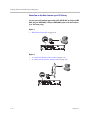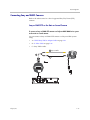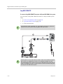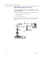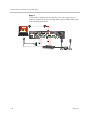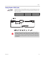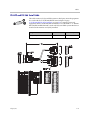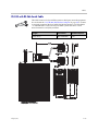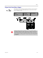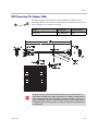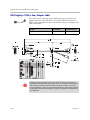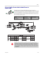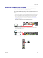
1
Integrator’s Reference Manual for Polycom® HDX® Systems 3.0.3 | October 2011 | 3725-23979-009/A Trademark Information Polycom®, the Polycom “Triangles” logo, and the names and marks associated with Polycom’s products are trademarks and/or service marks of Polycom, Inc., and are registered and/or common-law marks in the United States and various other countries. All other trademarks are the property of their respective owners. Patent Information The accompanying product may be protected by one or more U.S. and foreign patents and/or pending patent applications held by Polycom, Inc. Customer Feedback We are constantly working to improve the quality of our documentation, and we would appreciate your feedback. Please send email to [email protected]. © 2011 Polycom, Inc. All rights reserved. Polycom, Inc. 4750 Willow Road Pleasanton, CA 94588-2708 USA No part of this document may be reproduced or transmitted in any form or by any means, electronic or mechanical, for any purpose, without the express written permission of Polycom, Inc. Under the law, reproducing includes translating into another language or format. As between the parties, Polycom, Inc., retains title to and ownership of all proprietary rights with respect to the software contained within its products. The software is protected by United States copyright laws and international treaty provision. Therefore, you must treat the software like any other copyrighted material (e.g., a book or sound recording). Every effort has been made to ensure that the information in this manual is accurate. Polycom, Inc., is not responsible for printing or clerical errors. Information in this document is subject to change without notice. ii About This Guide The Integrator’s Reference Manual for Polycom® HDX® Systems is for system integrators who need to configure, customize, manage, and troubleshoot Polycom HDX systems. The API commands in this guide are applicable to the Polycom HDX 9000 series, Polycom HDX 8000 HD series, Polycom HDX 7000 HD series and Polycom HDX 6000 HD series systems. Polycom, Inc. iii Integrator’s Reference Manual for Polycom HDX Systems iv About This Guide Polycom, Inc. Contents About This Guide . . . . . . . . . . . . . . . . . . . . . . . . . . . . . . . . iii 1 Room Integration Setting Up a Room for Video Conferencing . . . . . . . . . . . . . . . . . . . . . . . . 1–1 Room Layout Examples . . . . . . . . . . . . . . . . . . . . . . . . . . . . . . . . . . . . . . 1–1 Setting Up the Room for Polycom People On Content™ . . . . . . . . . . 1–3 Polycom HDX Installation Precautions . . . . . . . . . . . . . . . . . . . . . . . . . 1–4 Integrating Video . . . . . . . . . . . . . . . . . . . . . . . . . . . . . . . . . . . . . . . . . . . . . . . 1–5 Connecting Polycom Cameras . . . . . . . . . . . . . . . . . . . . . . . . . . . . . . . . 1–5 Connecting Sony and ELMO Cameras . . . . . . . . . . . . . . . . . . . . . . . . 1–17 Connecting Vaddio and Canon Cameras . . . . . . . . . . . . . . . . . . . . . . 1–19 Integrating Audio and Content . . . . . . . . . . . . . . . . . . . . . . . . . . . . . . . . . . 1–21 Connecting a Computer to a Polycom HDX 9000 Series System . . 1–21 Connecting a Vortex® Mixer to a Polycom HDX 9000 Series System . . . . . . . . . . . . . . . . . . . . . . . . . . . . . . . . . . . . . . . . . . . . . . . . . . . 1–25 Connecting a Polycom SoundStructure C-Series Mixer to a Polycom HDX 9000 Series System . . . . . . . . . . . . . . . . . . . . . . . . . . . . 1–26 2 Cables Network Cables . . . . . . . . . . . . . . . . . . . . . . . . . . . . . . . . . . . . . . . . . . . . . . . . 2–1 CAT 5e LAN Cable . . . . . . . . . . . . . . . . . . . . . . . . . . . . . . . . . . . . . . . . . . 2–1 LAN Cable . . . . . . . . . . . . . . . . . . . . . . . . . . . . . . . . . . . . . . . . . . . . . . . . . 2–3 Polycom Touch Control LAN Cable . . . . . . . . . . . . . . . . . . . . . . . . . . . 2–4 ISDN Cable . . . . . . . . . . . . . . . . . . . . . . . . . . . . . . . . . . . . . . . . . . . . . . . . 2–5 Analog Telephone (POTS) Cable . . . . . . . . . . . . . . . . . . . . . . . . . . . . . . 2–7 V.35/RS-449/RS-530 Serial Adapter . . . . . . . . . . . . . . . . . . . . . . . . . . . 2–8 V.35 NIC Cable . . . . . . . . . . . . . . . . . . . . . . . . . . . . . . . . . . . . . . . . . . . . . 2–9 V.35 and RS-366 Serial Cable . . . . . . . . . . . . . . . . . . . . . . . . . . . . . . . . 2–10 RS-449 and RS-366 Serial Cable . . . . . . . . . . . . . . . . . . . . . . . . . . . . . . 2–11 RS-530 with RS-366 Serial Cable . . . . . . . . . . . . . . . . . . . . . . . . . . . . . . 2–13 Polycom Touch Control Power Adapter . . . . . . . . . . . . . . . . . . . . . . . 2–15 Video and Camera Cables . . . . . . . . . . . . . . . . . . . . . . . . . . . . . . . . . . . . . . 2–16 Polycom, Inc. v Integrator’s Reference Manual for Polycom HDX Systems S-Video Cable . . . . . . . . . . . . . . . . . . . . . . . . . . . . . . . . . . . . . . . . . . . . . 2–16 BNC to S-Video Cable . . . . . . . . . . . . . . . . . . . . . . . . . . . . . . . . . . . . . . 2–17 BNC to S-Video Adapter . . . . . . . . . . . . . . . . . . . . . . . . . . . . . . . . . . . . 2–18 S-Video to RCA Adapter . . . . . . . . . . . . . . . . . . . . . . . . . . . . . . . . . . . . 2–19 DVI to VGA Monitor Cable . . . . . . . . . . . . . . . . . . . . . . . . . . . . . . . . . . 2–20 HDMI Monitor Cable . . . . . . . . . . . . . . . . . . . . . . . . . . . . . . . . . . . . . . . 2–21 BNC Monitor Adapter Cable . . . . . . . . . . . . . . . . . . . . . . . . . . . . . . . . 2–22 Polycom HDX Component Monitor Cable . . . . . . . . . . . . . . . . . . . . . 2–23 HDX Component Video Cable . . . . . . . . . . . . . . . . . . . . . . . . . . . . . . . 2–24 DVI-D Monitor Cable . . . . . . . . . . . . . . . . . . . . . . . . . . . . . . . . . . . . . . . 2–25 Component A/V Monitor Cable . . . . . . . . . . . . . . . . . . . . . . . . . . . . . 2–26 HDCI Analog Camera Cable . . . . . . . . . . . . . . . . . . . . . . . . . . . . . . . . 2–27 HDCI Polycom EagleEye Director Camera Cable . . . . . . . . . . . . . . . 2–28 HDCI Camera Break-Out Cable . . . . . . . . . . . . . . . . . . . . . . . . . . . . . . 2–30 VCR/DVD Composite Cable . . . . . . . . . . . . . . . . . . . . . . . . . . . . . . . . 2–31 Composite Video Cable . . . . . . . . . . . . . . . . . . . . . . . . . . . . . . . . . . . . . 2–32 PowerCam Plus Primary Cable . . . . . . . . . . . . . . . . . . . . . . . . . . . . . . 2–33 HDCI PowerCam Cable . . . . . . . . . . . . . . . . . . . . . . . . . . . . . . . . . . . . . 2–34 HDCI PowerCam Plus Adapter Cable . . . . . . . . . . . . . . . . . . . . . . . . 2–35 HDCI VISCA Adapter Cable . . . . . . . . . . . . . . . . . . . . . . . . . . . . . . . . 2–36 HDCI Polycom EagleEye 1080 Camera Cable . . . . . . . . . . . . . . . . . . 2–37 HDCI Polycom EagleEye View Camera Cable . . . . . . . . . . . . . . . . . 2–38 HDCI Sony VISCA Adapter Cable . . . . . . . . . . . . . . . . . . . . . . . . . . . 2–39 HDCI EagleEye 1080 or Sony Adapter Cable . . . . . . . . . . . . . . . . . . . 2–40 PowerCam Primary Camera Cable . . . . . . . . . . . . . . . . . . . . . . . . . . . 2–41 PowerCam Break-Out Cable . . . . . . . . . . . . . . . . . . . . . . . . . . . . . . . . . 2–42 PowerCam Plus/VISCA Control Cable . . . . . . . . . . . . . . . . . . . . . . . 2–43 People+Content Cable . . . . . . . . . . . . . . . . . . . . . . . . . . . . . . . . . . . . . . 2–45 Audio Cables . . . . . . . . . . . . . . . . . . . . . . . . . . . . . . . . . . . . . . . . . . . . . . . . . 2–46 Polycom HDX Microphone Host Cable . . . . . . . . . . . . . . . . . . . . . . . 2–46 Polycom HDX Microphone Array Cable . . . . . . . . . . . . . . . . . . . . . . 2–48 Polycom HDX Microphone Array Cable Adapter . . . . . . . . . . . . . . 2–49 Polycom HDX Ceiling Microphone Adaptor Cable . . . . . . . . . . . . . 2–50 Custom Cabling for Polycom HDX Microphones . . . . . . . . . . . . . . . 2–51 Audio Adapter Cable . . . . . . . . . . . . . . . . . . . . . . . . . . . . . . . . . . . . . . . 2–54 Audio Cable . . . . . . . . . . . . . . . . . . . . . . . . . . . . . . . . . . . . . . . . . . . . . . . 2–55 Vortex Cable . . . . . . . . . . . . . . . . . . . . . . . . . . . . . . . . . . . . . . . . . . . . . . 2–56 3.5mm Screw Cage Connector . . . . . . . . . . . . . . . . . . . . . . . . . . . . . . . 2–57 Subwoofer Volume Attenuator . . . . . . . . . . . . . . . . . . . . . . . . . . . . . . 2–58 vi Polycom, Inc. Contents Polycom EagleEye Director Audio Feedback Phoenix to Phoenix Cable . . . . . . . . . . . . . . . . . . . . . . . . . . . . . . . . . . . . . . . . . . . . . 2–59 Serial Cables . . . . . . . . . . . . . . . . . . . . . . . . . . . . . . . . . . . . . . . . . . . . . . . . . . 2–60 Straight-Through Serial Cable . . . . . . . . . . . . . . . . . . . . . . . . . . . . . . . 2–60 Null Modem Adapter . . . . . . . . . . . . . . . . . . . . . . . . . . . . . . . . . . . . . . 2–62 3 Using the API Using the API with an RS-232 Interface . . . . . . . . . . . . . . . . . . . . . . . . . . . . 3–1 Configuring the RS-232 Interface . . . . . . . . . . . . . . . . . . . . . . . . . . . . . . 3–1 Starting an API Session using an RS-232 Interface . . . . . . . . . . . . . . . 3–3 Using the API with the Maximum Security Profile Enabled . . . . . . . 3–4 Using the API with a LAN Connection . . . . . . . . . . . . . . . . . . . . . . . . . . . . 3–4 Using the API Controller Code . . . . . . . . . . . . . . . . . . . . . . . . . . . . . . . . . . . 3–4 Additional API Resources . . . . . . . . . . . . . . . . . . . . . . . . . . . . . . . . . . . . . . . 3–5 Technical Support Contact Information . . . . . . . . . . . . . . . . . . . . . . . . 3–5 Feature Enhancement Request Web Site . . . . . . . . . . . . . . . . . . . . . . . . 3–5 Video Test Numbers . . . . . . . . . . . . . . . . . . . . . . . . . . . . . . . . . . . . . . . . 3–5 Knowledge Base . . . . . . . . . . . . . . . . . . . . . . . . . . . . . . . . . . . . . . . . . . . . 3–5 4 System Commands About the API Commands . . . . . . . . . . . . . . . . . . . . . . . . . . . . . . . . . . . . . . . 4–2 Syntax Conventions . . . . . . . . . . . . . . . . . . . . . . . . . . . . . . . . . . . . . . . . . 4–2 Availability of Commands . . . . . . . . . . . . . . . . . . . . . . . . . . . . . . . . . . . 4–2 Command Response Syntax . . . . . . . . . . . . . . . . . . . . . . . . . . . . . . . . . . 4–3 Commands that Restart the System . . . . . . . . . . . . . . . . . . . . . . . . . . . . 4–5 Additional Tips . . . . . . . . . . . . . . . . . . . . . . . . . . . . . . . . . . . . . . . . . . . . . 4–5 ! . . . . . . . . . . . . . . . . . . . . . . . . . . . . . . . . . . . . . . . . . . . . . . . . . . . . . . . . . . . . . . 4–7 abk (deprecated) . . . . . . . . . . . . . . . . . . . . . . . . . . . . . . . . . . . . . . . . . . . . . . . 4–9 addrbook . . . . . . . . . . . . . . . . . . . . . . . . . . . . . . . . . . . . . . . . . . . . . . . . . . . . . 4–12 addressdisplayedingab . . . . . . . . . . . . . . . . . . . . . . . . . . . . . . . . . . . . . . . . . 4–14 advnetstats . . . . . . . . . . . . . . . . . . . . . . . . . . . . . . . . . . . . . . . . . . . . . . . . . . . 4–15 alertusertone . . . . . . . . . . . . . . . . . . . . . . . . . . . . . . . . . . . . . . . . . . . . . . . . . . 4–17 alertvideotone . . . . . . . . . . . . . . . . . . . . . . . . . . . . . . . . . . . . . . . . . . . . . . . . . 4–18 all register . . . . . . . . . . . . . . . . . . . . . . . . . . . . . . . . . . . . . . . . . . . . . . . . . . . . 4–19 all unregister . . . . . . . . . . . . . . . . . . . . . . . . . . . . . . . . . . . . . . . . . . . . . . . . . . 4–21 allowabkchanges . . . . . . . . . . . . . . . . . . . . . . . . . . . . . . . . . . . . . . . . . . . . . . 4–22 allowcamerapresetssetup . . . . . . . . . . . . . . . . . . . . . . . . . . . . . . . . . . . . . . . 4–23 allowdialing . . . . . . . . . . . . . . . . . . . . . . . . . . . . . . . . . . . . . . . . . . . . . . . . . . 4–24 allowmixedcalls . . . . . . . . . . . . . . . . . . . . . . . . . . . . . . . . . . . . . . . . . . . . . . . 4–25 allowusersetup . . . . . . . . . . . . . . . . . . . . . . . . . . . . . . . . . . . . . . . . . . . . . . . . 4–26 Polycom, Inc. vii Integrator’s Reference Manual for Polycom HDX Systems amxdd . . . . . . . . . . . . . . . . . . . . . . . . . . . . . . . . . . . . . . . . . . . . . . . . . . . . . . . 4–27 answer . . . . . . . . . . . . . . . . . . . . . . . . . . . . . . . . . . . . . . . . . . . . . . . . . . . . . . . 4–28 areacode . . . . . . . . . . . . . . . . . . . . . . . . . . . . . . . . . . . . . . . . . . . . . . . . . . . . . 4–29 audiometer . . . . . . . . . . . . . . . . . . . . . . . . . . . . . . . . . . . . . . . . . . . . . . . . . . . 4–30 audiotransmitlevel . . . . . . . . . . . . . . . . . . . . . . . . . . . . . . . . . . . . . . . . . . . . . 4–32 autoanswer . . . . . . . . . . . . . . . . . . . . . . . . . . . . . . . . . . . . . . . . . . . . . . . . . . . 4–34 autoshowcontent . . . . . . . . . . . . . . . . . . . . . . . . . . . . . . . . . . . . . . . . . . . . . . 4–35 backlightcompensation . . . . . . . . . . . . . . . . . . . . . . . . . . . . . . . . . . . . . . . . . 4–36 basicmode . . . . . . . . . . . . . . . . . . . . . . . . . . . . . . . . . . . . . . . . . . . . . . . . . . . . 4–37 bri1enable, bri2enable, bri3enable, bri4enable . . . . . . . . . . . . . . . . . . . . . 4–38 briallenable . . . . . . . . . . . . . . . . . . . . . . . . . . . . . . . . . . . . . . . . . . . . . . . . . . . 4–39 button . . . . . . . . . . . . . . . . . . . . . . . . . . . . . . . . . . . . . . . . . . . . . . . . . . . . . . . . 4–40 calendardomain . . . . . . . . . . . . . . . . . . . . . . . . . . . . . . . . . . . . . . . . . . . . . . . 4–44 calendarmeetings . . . . . . . . . . . . . . . . . . . . . . . . . . . . . . . . . . . . . . . . . . . . . . 4–45 calendarpassword . . . . . . . . . . . . . . . . . . . . . . . . . . . . . . . . . . . . . . . . . . . . . 4–50 calendarplaytone . . . . . . . . . . . . . . . . . . . . . . . . . . . . . . . . . . . . . . . . . . . . . . 4–51 calendarregisterwithserver . . . . . . . . . . . . . . . . . . . . . . . . . . . . . . . . . . . . . . 4–52 calendarremindertime . . . . . . . . . . . . . . . . . . . . . . . . . . . . . . . . . . . . . . . . . . 4–53 calendarresource . . . . . . . . . . . . . . . . . . . . . . . . . . . . . . . . . . . . . . . . . . . . . . 4–54 calendarserver . . . . . . . . . . . . . . . . . . . . . . . . . . . . . . . . . . . . . . . . . . . . . . . . 4–55 calendarshowpvtmeetings . . . . . . . . . . . . . . . . . . . . . . . . . . . . . . . . . . . . . . 4–56 calendarstatus . . . . . . . . . . . . . . . . . . . . . . . . . . . . . . . . . . . . . . . . . . . . . . . . . 4–57 calendaruser . . . . . . . . . . . . . . . . . . . . . . . . . . . . . . . . . . . . . . . . . . . . . . . . . . 4–58 calldetail . . . . . . . . . . . . . . . . . . . . . . . . . . . . . . . . . . . . . . . . . . . . . . . . . . . . . 4–59 calldetailreport . . . . . . . . . . . . . . . . . . . . . . . . . . . . . . . . . . . . . . . . . . . . . . . . 4–60 callinfo . . . . . . . . . . . . . . . . . . . . . . . . . . . . . . . . . . . . . . . . . . . . . . . . . . . . . . . 4–61 callstate . . . . . . . . . . . . . . . . . . . . . . . . . . . . . . . . . . . . . . . . . . . . . . . . . . . . . . 4–62 callstats . . . . . . . . . . . . . . . . . . . . . . . . . . . . . . . . . . . . . . . . . . . . . . . . . . . . . . 4–64 camera . . . . . . . . . . . . . . . . . . . . . . . . . . . . . . . . . . . . . . . . . . . . . . . . . . . . . . . 4–65 cameradirection . . . . . . . . . . . . . . . . . . . . . . . . . . . . . . . . . . . . . . . . . . . . . . . 4–69 camerainput . . . . . . . . . . . . . . . . . . . . . . . . . . . . . . . . . . . . . . . . . . . . . . . . . . 4–70 chaircontrol . . . . . . . . . . . . . . . . . . . . . . . . . . . . . . . . . . . . . . . . . . . . . . . . . . . 4–71 clientvalidatepeercert . . . . . . . . . . . . . . . . . . . . . . . . . . . . . . . . . . . . . . . . . . 4–73 cmdecho . . . . . . . . . . . . . . . . . . . . . . . . . . . . . . . . . . . . . . . . . . . . . . . . . . . . . 4–74 colorbar . . . . . . . . . . . . . . . . . . . . . . . . . . . . . . . . . . . . . . . . . . . . . . . . . . . . . . 4–75 configchange (deprecated) . . . . . . . . . . . . . . . . . . . . . . . . . . . . . . . . . . . . . . 4–76 configdisplay . . . . . . . . . . . . . . . . . . . . . . . . . . . . . . . . . . . . . . . . . . . . . . . . . 4–77 configparam . . . . . . . . . . . . . . . . . . . . . . . . . . . . . . . . . . . . . . . . . . . . . . . . . . 4–79 configpresentation . . . . . . . . . . . . . . . . . . . . . . . . . . . . . . . . . . . . . . . . . . . . . 4–80 confirmdiradd . . . . . . . . . . . . . . . . . . . . . . . . . . . . . . . . . . . . . . . . . . . . . . . . 4–82 viii Polycom, Inc. Contents confirmdirdel . . . . . . . . . . . . . . . . . . . . . . . . . . . . . . . . . . . . . . . . . . . . . . . . . 4–83 contentauto . . . . . . . . . . . . . . . . . . . . . . . . . . . . . . . . . . . . . . . . . . . . . . . . . . . 4–84 contentsplash . . . . . . . . . . . . . . . . . . . . . . . . . . . . . . . . . . . . . . . . . . . . . . . . . 4–85 contentvideoadjustment . . . . . . . . . . . . . . . . . . . . . . . . . . . . . . . . . . . . . . . . 4–86 country . . . . . . . . . . . . . . . . . . . . . . . . . . . . . . . . . . . . . . . . . . . . . . . . . . . . . . 4–87 cts . . . . . . . . . . . . . . . . . . . . . . . . . . . . . . . . . . . . . . . . . . . . . . . . . . . . . . . . . . . 4–88 daylightsavings . . . . . . . . . . . . . . . . . . . . . . . . . . . . . . . . . . . . . . . . . . . . . . . 4–89 dcd . . . . . . . . . . . . . . . . . . . . . . . . . . . . . . . . . . . . . . . . . . . . . . . . . . . . . . . . . . 4–90 dcdfilter . . . . . . . . . . . . . . . . . . . . . . . . . . . . . . . . . . . . . . . . . . . . . . . . . . . . . . 4–91 defaultgateway . . . . . . . . . . . . . . . . . . . . . . . . . . . . . . . . . . . . . . . . . . . . . . . . 4–92 destunreachabletx . . . . . . . . . . . . . . . . . . . . . . . . . . . . . . . . . . . . . . . . . . . . . 4–93 dhcp . . . . . . . . . . . . . . . . . . . . . . . . . . . . . . . . . . . . . . . . . . . . . . . . . . . . . . . . . 4–94 dial . . . . . . . . . . . . . . . . . . . . . . . . . . . . . . . . . . . . . . . . . . . . . . . . . . . . . . . . . . 4–95 dialchannels . . . . . . . . . . . . . . . . . . . . . . . . . . . . . . . . . . . . . . . . . . . . . . . . . . 4–99 diffservaudio, diffservfecc, diffservvideo . . . . . . . . . . . . . . . . . . . . . . . . 4–100 directory . . . . . . . . . . . . . . . . . . . . . . . . . . . . . . . . . . . . . . . . . . . . . . . . . . . . 4–101 display (deprecated) . . . . . . . . . . . . . . . . . . . . . . . . . . . . . . . . . . . . . . . . . . 4–102 displayglobaladdresses . . . . . . . . . . . . . . . . . . . . . . . . . . . . . . . . . . . . . . . . 4–104 displaygraphics . . . . . . . . . . . . . . . . . . . . . . . . . . . . . . . . . . . . . . . . . . . . . . 4–105 displayipext . . . . . . . . . . . . . . . . . . . . . . . . . . . . . . . . . . . . . . . . . . . . . . . . . 4–106 displayipisdninfo (deprecated) . . . . . . . . . . . . . . . . . . . . . . . . . . . . . . . . . 4–107 displayparams . . . . . . . . . . . . . . . . . . . . . . . . . . . . . . . . . . . . . . . . . . . . . . . 4–108 dns . . . . . . . . . . . . . . . . . . . . . . . . . . . . . . . . . . . . . . . . . . . . . . . . . . . . . . . . . 4–110 dsr . . . . . . . . . . . . . . . . . . . . . . . . . . . . . . . . . . . . . . . . . . . . . . . . . . . . . . . . . . 4–111 dsranswer . . . . . . . . . . . . . . . . . . . . . . . . . . . . . . . . . . . . . . . . . . . . . . . . . . . 4–112 dtr . . . . . . . . . . . . . . . . . . . . . . . . . . . . . . . . . . . . . . . . . . . . . . . . . . . . . . . . . . 4–113 dualmonitor . . . . . . . . . . . . . . . . . . . . . . . . . . . . . . . . . . . . . . . . . . . . . . . . . 4–114 dynamicbandwidth . . . . . . . . . . . . . . . . . . . . . . . . . . . . . . . . . . . . . . . . . . . 4–115 e164ext . . . . . . . . . . . . . . . . . . . . . . . . . . . . . . . . . . . . . . . . . . . . . . . . . . . . . . 4–116 echo . . . . . . . . . . . . . . . . . . . . . . . . . . . . . . . . . . . . . . . . . . . . . . . . . . . . . . . . 4–117 echocanceller . . . . . . . . . . . . . . . . . . . . . . . . . . . . . . . . . . . . . . . . . . . . . . . . 4–118 echoreply . . . . . . . . . . . . . . . . . . . . . . . . . . . . . . . . . . . . . . . . . . . . . . . . . . . . 4–119 enablefirewalltraversal . . . . . . . . . . . . . . . . . . . . . . . . . . . . . . . . . . . . . . . . 4–120 enablekeyboardnoisereduction . . . . . . . . . . . . . . . . . . . . . . . . . . . . . . . . . 4–121 enablelivemusicmode . . . . . . . . . . . . . . . . . . . . . . . . . . . . . . . . . . . . . . . . . 4–122 enablepvec . . . . . . . . . . . . . . . . . . . . . . . . . . . . . . . . . . . . . . . . . . . . . . . . . . 4–123 enablersvp . . . . . . . . . . . . . . . . . . . . . . . . . . . . . . . . . . . . . . . . . . . . . . . . . . . 4–124 enablesnmp . . . . . . . . . . . . . . . . . . . . . . . . . . . . . . . . . . . . . . . . . . . . . . . . . . 4–125 encryption . . . . . . . . . . . . . . . . . . . . . . . . . . . . . . . . . . . . . . . . . . . . . . . . . . . 4–126 exit . . . . . . . . . . . . . . . . . . . . . . . . . . . . . . . . . . . . . . . . . . . . . . . . . . . . . . . . . 4–128 Polycom, Inc. ix Integrator’s Reference Manual for Polycom HDX Systems exportdirectory . . . . . . . . . . . . . . . . . . . . . . . . . . . . . . . . . . . . . . . . . . . . . . . 4–129 exportprofile . . . . . . . . . . . . . . . . . . . . . . . . . . . . . . . . . . . . . . . . . . . . . . . . . 4–131 farcontrolnearcamera . . . . . . . . . . . . . . . . . . . . . . . . . . . . . . . . . . . . . . . . . 4–133 farnametimedisplay . . . . . . . . . . . . . . . . . . . . . . . . . . . . . . . . . . . . . . . . . . . 4–134 flash . . . . . . . . . . . . . . . . . . . . . . . . . . . . . . . . . . . . . . . . . . . . . . . . . . . . . . . . 4–135 gabk (deprecated) . . . . . . . . . . . . . . . . . . . . . . . . . . . . . . . . . . . . . . . . . . . . 4–136 gabpassword . . . . . . . . . . . . . . . . . . . . . . . . . . . . . . . . . . . . . . . . . . . . . . . . 4–139 gabserverip . . . . . . . . . . . . . . . . . . . . . . . . . . . . . . . . . . . . . . . . . . . . . . . . . . 4–140 gaddrbook . . . . . . . . . . . . . . . . . . . . . . . . . . . . . . . . . . . . . . . . . . . . . . . . . . . 4–141 gatekeeperip . . . . . . . . . . . . . . . . . . . . . . . . . . . . . . . . . . . . . . . . . . . . . . . . . 4–144 gatewayareacode . . . . . . . . . . . . . . . . . . . . . . . . . . . . . . . . . . . . . . . . . . . . . 4–145 gatewaycountrycode . . . . . . . . . . . . . . . . . . . . . . . . . . . . . . . . . . . . . . . . . . 4–146 gatewayext . . . . . . . . . . . . . . . . . . . . . . . . . . . . . . . . . . . . . . . . . . . . . . . . . . 4–147 gatewaynumber . . . . . . . . . . . . . . . . . . . . . . . . . . . . . . . . . . . . . . . . . . . . . . 4–148 gatewaynumbertype . . . . . . . . . . . . . . . . . . . . . . . . . . . . . . . . . . . . . . . . . . 4–149 gatewayprefix . . . . . . . . . . . . . . . . . . . . . . . . . . . . . . . . . . . . . . . . . . . . . . . . 4–150 gatewaysetup . . . . . . . . . . . . . . . . . . . . . . . . . . . . . . . . . . . . . . . . . . . . . . . . 4–151 gatewaysuffix . . . . . . . . . . . . . . . . . . . . . . . . . . . . . . . . . . . . . . . . . . . . . . . . 4–152 gdsdirectory . . . . . . . . . . . . . . . . . . . . . . . . . . . . . . . . . . . . . . . . . . . . . . . . . 4–153 gendial . . . . . . . . . . . . . . . . . . . . . . . . . . . . . . . . . . . . . . . . . . . . . . . . . . . . . . 4–154 gendialtonepots (deprecated) . . . . . . . . . . . . . . . . . . . . . . . . . . . . . . . . . . 4–155 generatetone . . . . . . . . . . . . . . . . . . . . . . . . . . . . . . . . . . . . . . . . . . . . . . . . . 4–156 get screen . . . . . . . . . . . . . . . . . . . . . . . . . . . . . . . . . . . . . . . . . . . . . . . . . . . . 4–157 getcallstate . . . . . . . . . . . . . . . . . . . . . . . . . . . . . . . . . . . . . . . . . . . . . . . . . . 4–158 getconfiguredipaddress . . . . . . . . . . . . . . . . . . . . . . . . . . . . . . . . . . . . . . . 4–159 gmscity . . . . . . . . . . . . . . . . . . . . . . . . . . . . . . . . . . . . . . . . . . . . . . . . . . . . . 4–160 gmscontactemail . . . . . . . . . . . . . . . . . . . . . . . . . . . . . . . . . . . . . . . . . . . . . 4–161 gmscontactfax . . . . . . . . . . . . . . . . . . . . . . . . . . . . . . . . . . . . . . . . . . . . . . . . 4–162 gmscontactnumber . . . . . . . . . . . . . . . . . . . . . . . . . . . . . . . . . . . . . . . . . . . 4–163 gmscontactperson . . . . . . . . . . . . . . . . . . . . . . . . . . . . . . . . . . . . . . . . . . . . 4–164 gmscountry . . . . . . . . . . . . . . . . . . . . . . . . . . . . . . . . . . . . . . . . . . . . . . . . . . 4–165 gmsstate . . . . . . . . . . . . . . . . . . . . . . . . . . . . . . . . . . . . . . . . . . . . . . . . . . . . . 4–166 gmstechsupport . . . . . . . . . . . . . . . . . . . . . . . . . . . . . . . . . . . . . . . . . . . . . . 4–167 gmsurl . . . . . . . . . . . . . . . . . . . . . . . . . . . . . . . . . . . . . . . . . . . . . . . . . . . . . . 4–168 h239enable . . . . . . . . . . . . . . . . . . . . . . . . . . . . . . . . . . . . . . . . . . . . . . . . . . 4–169 h323name . . . . . . . . . . . . . . . . . . . . . . . . . . . . . . . . . . . . . . . . . . . . . . . . . . . 4–170 h331audiomode . . . . . . . . . . . . . . . . . . . . . . . . . . . . . . . . . . . . . . . . . . . . . . 4–171 h331dualstream . . . . . . . . . . . . . . . . . . . . . . . . . . . . . . . . . . . . . . . . . . . . . . 4–172 h331framerate . . . . . . . . . . . . . . . . . . . . . . . . . . . . . . . . . . . . . . . . . . . . . . . . 4–173 h331videoformat . . . . . . . . . . . . . . . . . . . . . . . . . . . . . . . . . . . . . . . . . . . . . 4–174 x Polycom, Inc. Contents h331videoprotocol . . . . . . . . . . . . . . . . . . . . . . . . . . . . . . . . . . . . . . . . . . . . 4–175 hangup . . . . . . . . . . . . . . . . . . . . . . . . . . . . . . . . . . . . . . . . . . . . . . . . . . . . . . 4–176 history . . . . . . . . . . . . . . . . . . . . . . . . . . . . . . . . . . . . . . . . . . . . . . . . . . . . . . 4–177 homecallquality . . . . . . . . . . . . . . . . . . . . . . . . . . . . . . . . . . . . . . . . . . . . . . 4–178 homemultipoint (deprecated) . . . . . . . . . . . . . . . . . . . . . . . . . . . . . . . . . . 4–179 homerecentcalls . . . . . . . . . . . . . . . . . . . . . . . . . . . . . . . . . . . . . . . . . . . . . . 4–180 homesystem . . . . . . . . . . . . . . . . . . . . . . . . . . . . . . . . . . . . . . . . . . . . . . . . . 4–181 homesystemname . . . . . . . . . . . . . . . . . . . . . . . . . . . . . . . . . . . . . . . . . . . . 4–182 hostname . . . . . . . . . . . . . . . . . . . . . . . . . . . . . . . . . . . . . . . . . . . . . . . . . . . . 4–183 icmpoutpacketrate . . . . . . . . . . . . . . . . . . . . . . . . . . . . . . . . . . . . . . . . . . . . 4–185 ignoreredirect . . . . . . . . . . . . . . . . . . . . . . . . . . . . . . . . . . . . . . . . . . . . . . . . 4–186 importdirectory . . . . . . . . . . . . . . . . . . . . . . . . . . . . . . . . . . . . . . . . . . . . . . 4–187 importprofile . . . . . . . . . . . . . . . . . . . . . . . . . . . . . . . . . . . . . . . . . . . . . . . . 4–190 incompleterevocationcheck . . . . . . . . . . . . . . . . . . . . . . . . . . . . . . . . . . . . 4–192 ipaddress . . . . . . . . . . . . . . . . . . . . . . . . . . . . . . . . . . . . . . . . . . . . . . . . . . . . 4–193 ipdialspeed . . . . . . . . . . . . . . . . . . . . . . . . . . . . . . . . . . . . . . . . . . . . . . . . . . 4–194 ipisdninfo . . . . . . . . . . . . . . . . . . . . . . . . . . . . . . . . . . . . . . . . . . . . . . . . . . . 4–196 ipprecaudio, ipprecfecc, ipprecvideo . . . . . . . . . . . . . . . . . . . . . . . . . . . . 4–197 ipv6addrmode . . . . . . . . . . . . . . . . . . . . . . . . . . . . . . . . . . . . . . . . . . . . . . . 4–198 ipv6globaladdress . . . . . . . . . . . . . . . . . . . . . . . . . . . . . . . . . . . . . . . . . . . . 4–199 ipv6defaultgateway . . . . . . . . . . . . . . . . . . . . . . . . . . . . . . . . . . . . . . . . . . . 4–200 ipv6linklocal . . . . . . . . . . . . . . . . . . . . . . . . . . . . . . . . . . . . . . . . . . . . . . . . . 4–201 ipv6sitelocal . . . . . . . . . . . . . . . . . . . . . . . . . . . . . . . . . . . . . . . . . . . . . . . . . 4–202 ipstat . . . . . . . . . . . . . . . . . . . . . . . . . . . . . . . . . . . . . . . . . . . . . . . . . . . . . . . 4–203 isdnareacode . . . . . . . . . . . . . . . . . . . . . . . . . . . . . . . . . . . . . . . . . . . . . . . . . 4–204 isdncountrycode . . . . . . . . . . . . . . . . . . . . . . . . . . . . . . . . . . . . . . . . . . . . . 4–205 isdndialingprefix . . . . . . . . . . . . . . . . . . . . . . . . . . . . . . . . . . . . . . . . . . . . . 4–206 isdndialspeed . . . . . . . . . . . . . . . . . . . . . . . . . . . . . . . . . . . . . . . . . . . . . . . . 4–207 isdnnum . . . . . . . . . . . . . . . . . . . . . . . . . . . . . . . . . . . . . . . . . . . . . . . . . . . . 4–209 isdnswitch . . . . . . . . . . . . . . . . . . . . . . . . . . . . . . . . . . . . . . . . . . . . . . . . . . . 4–210 keypadaudioconf . . . . . . . . . . . . . . . . . . . . . . . . . . . . . . . . . . . . . . . . . . . . . 4–211 language . . . . . . . . . . . . . . . . . . . . . . . . . . . . . . . . . . . . . . . . . . . . . . . . . . . . 4–212 lanport . . . . . . . . . . . . . . . . . . . . . . . . . . . . . . . . . . . . . . . . . . . . . . . . . . . . . . 4–213 ldapauthenticationtype . . . . . . . . . . . . . . . . . . . . . . . . . . . . . . . . . . . . . . . . 4–214 ldapbasedn . . . . . . . . . . . . . . . . . . . . . . . . . . . . . . . . . . . . . . . . . . . . . . . . . . 4–215 ldapbinddn . . . . . . . . . . . . . . . . . . . . . . . . . . . . . . . . . . . . . . . . . . . . . . . . . . 4–216 ldapdirectory . . . . . . . . . . . . . . . . . . . . . . . . . . . . . . . . . . . . . . . . . . . . . . . . 4–217 ldapntlmdomain . . . . . . . . . . . . . . . . . . . . . . . . . . . . . . . . . . . . . . . . . . . . . 4–218 ldappassword . . . . . . . . . . . . . . . . . . . . . . . . . . . . . . . . . . . . . . . . . . . . . . . . 4–219 ldapserveraddress . . . . . . . . . . . . . . . . . . . . . . . . . . . . . . . . . . . . . . . . . . . . 4–220 Polycom, Inc. xi Integrator’s Reference Manual for Polycom HDX Systems ldapserverport . . . . . . . . . . . . . . . . . . . . . . . . . . . . . . . . . . . . . . . . . . . . . . . 4–221 ldapsslenabled . . . . . . . . . . . . . . . . . . . . . . . . . . . . . . . . . . . . . . . . . . . . . . . 4–222 ldapusername . . . . . . . . . . . . . . . . . . . . . . . . . . . . . . . . . . . . . . . . . . . . . . . . 4–223 linestate . . . . . . . . . . . . . . . . . . . . . . . . . . . . . . . . . . . . . . . . . . . . . . . . . . . . . 4–224 listen . . . . . . . . . . . . . . . . . . . . . . . . . . . . . . . . . . . . . . . . . . . . . . . . . . . . . . . . 4–225 localdatetime . . . . . . . . . . . . . . . . . . . . . . . . . . . . . . . . . . . . . . . . . . . . . . . . 4–226 loginwindowduration . . . . . . . . . . . . . . . . . . . . . . . . . . . . . . . . . . . . . . . . . 4–227 marqueedisplaytext . . . . . . . . . . . . . . . . . . . . . . . . . . . . . . . . . . . . . . . . . . . 4–228 maxgabinternationalcallspeed . . . . . . . . . . . . . . . . . . . . . . . . . . . . . . . . . . 4–229 maxgabinternetcallspeed . . . . . . . . . . . . . . . . . . . . . . . . . . . . . . . . . . . . . . 4–230 maxgabisdncallspeed . . . . . . . . . . . . . . . . . . . . . . . . . . . . . . . . . . . . . . . . . 4–231 maxtimeincall . . . . . . . . . . . . . . . . . . . . . . . . . . . . . . . . . . . . . . . . . . . . . . . . 4–232 mcupassword . . . . . . . . . . . . . . . . . . . . . . . . . . . . . . . . . . . . . . . . . . . . . . . . 4–233 meetingpassword . . . . . . . . . . . . . . . . . . . . . . . . . . . . . . . . . . . . . . . . . . . . . 4–234 monitor1 (deprecated) . . . . . . . . . . . . . . . . . . . . . . . . . . . . . . . . . . . . . . . . . 4–235 monitor1screensaveroutput . . . . . . . . . . . . . . . . . . . . . . . . . . . . . . . . . . . . 4–236 monitor2 (deprecated) . . . . . . . . . . . . . . . . . . . . . . . . . . . . . . . . . . . . . . . . . 4–237 monitor2screensaveroutput . . . . . . . . . . . . . . . . . . . . . . . . . . . . . . . . . . . . 4–238 mpautoanswer . . . . . . . . . . . . . . . . . . . . . . . . . . . . . . . . . . . . . . . . . . . . . . . 4–239 mpmode . . . . . . . . . . . . . . . . . . . . . . . . . . . . . . . . . . . . . . . . . . . . . . . . . . . . 4–240 mtumode . . . . . . . . . . . . . . . . . . . . . . . . . . . . . . . . . . . . . . . . . . . . . . . . . . . . 4–242 mtusize . . . . . . . . . . . . . . . . . . . . . . . . . . . . . . . . . . . . . . . . . . . . . . . . . . . . . 4–243 mute . . . . . . . . . . . . . . . . . . . . . . . . . . . . . . . . . . . . . . . . . . . . . . . . . . . . . . . . 4–244 muteautoanswer . . . . . . . . . . . . . . . . . . . . . . . . . . . . . . . . . . . . . . . . . . . . . 4–245 natconfig . . . . . . . . . . . . . . . . . . . . . . . . . . . . . . . . . . . . . . . . . . . . . . . . . . . . 4–246 nath323compatible . . . . . . . . . . . . . . . . . . . . . . . . . . . . . . . . . . . . . . . . . . . . 4–247 nearloop . . . . . . . . . . . . . . . . . . . . . . . . . . . . . . . . . . . . . . . . . . . . . . . . . . . . 4–248 netstats . . . . . . . . . . . . . . . . . . . . . . . . . . . . . . . . . . . . . . . . . . . . . . . . . . . . . . 4–249 nonotify . . . . . . . . . . . . . . . . . . . . . . . . . . . . . . . . . . . . . . . . . . . . . . . . . . . . . 4–250 notify . . . . . . . . . . . . . . . . . . . . . . . . . . . . . . . . . . . . . . . . . . . . . . . . . . . . . . . 4–251 ntpmode . . . . . . . . . . . . . . . . . . . . . . . . . . . . . . . . . . . . . . . . . . . . . . . . . . . . 4–254 ntpsecondaryserver . . . . . . . . . . . . . . . . . . . . . . . . . . . . . . . . . . . . . . . . . . . 4–255 ntpserver . . . . . . . . . . . . . . . . . . . . . . . . . . . . . . . . . . . . . . . . . . . . . . . . . . . . 4–256 numberofmonitors (deprecated) . . . . . . . . . . . . . . . . . . . . . . . . . . . . . . . . 4–257 numdigitsdid . . . . . . . . . . . . . . . . . . . . . . . . . . . . . . . . . . . . . . . . . . . . . . . . 4–258 numdigitsext . . . . . . . . . . . . . . . . . . . . . . . . . . . . . . . . . . . . . . . . . . . . . . . . . 4–259 ocsdirectory . . . . . . . . . . . . . . . . . . . . . . . . . . . . . . . . . . . . . . . . . . . . . . . . . 4–260 oobcomplete . . . . . . . . . . . . . . . . . . . . . . . . . . . . . . . . . . . . . . . . . . . . . . . . . 4–262 pause . . . . . . . . . . . . . . . . . . . . . . . . . . . . . . . . . . . . . . . . . . . . . . . . . . . . . . . 4–263 peoplevideoadjustment . . . . . . . . . . . . . . . . . . . . . . . . . . . . . . . . . . . . . . . 4–264 xii Polycom, Inc. Contents phone . . . . . . . . . . . . . . . . . . . . . . . . . . . . . . . . . . . . . . . . . . . . . . . . . . . . . . . 4–265 pip . . . . . . . . . . . . . . . . . . . . . . . . . . . . . . . . . . . . . . . . . . . . . . . . . . . . . . . . . 4–266 popupinfo . . . . . . . . . . . . . . . . . . . . . . . . . . . . . . . . . . . . . . . . . . . . . . . . . . . 4–268 preset . . . . . . . . . . . . . . . . . . . . . . . . . . . . . . . . . . . . . . . . . . . . . . . . . . . . . . . 4–269 pricallbycall . . . . . . . . . . . . . . . . . . . . . . . . . . . . . . . . . . . . . . . . . . . . . . . . . 4–271 prichannel . . . . . . . . . . . . . . . . . . . . . . . . . . . . . . . . . . . . . . . . . . . . . . . . . . . 4–272 pricsu . . . . . . . . . . . . . . . . . . . . . . . . . . . . . . . . . . . . . . . . . . . . . . . . . . . . . . . 4–274 pridialchannels . . . . . . . . . . . . . . . . . . . . . . . . . . . . . . . . . . . . . . . . . . . . . . . 4–275 priintlprefix . . . . . . . . . . . . . . . . . . . . . . . . . . . . . . . . . . . . . . . . . . . . . . . . . . 4–276 prilinebuildout . . . . . . . . . . . . . . . . . . . . . . . . . . . . . . . . . . . . . . . . . . . . . . . 4–277 prilinesignal . . . . . . . . . . . . . . . . . . . . . . . . . . . . . . . . . . . . . . . . . . . . . . . . . 4–278 prinumberingplan . . . . . . . . . . . . . . . . . . . . . . . . . . . . . . . . . . . . . . . . . . . . 4–279 prioutsideline . . . . . . . . . . . . . . . . . . . . . . . . . . . . . . . . . . . . . . . . . . . . . . . . 4–280 priswitch . . . . . . . . . . . . . . . . . . . . . . . . . . . . . . . . . . . . . . . . . . . . . . . . . . . . 4–281 reboot . . . . . . . . . . . . . . . . . . . . . . . . . . . . . . . . . . . . . . . . . . . . . . . . . . . . . . . 4–282 recentcalls . . . . . . . . . . . . . . . . . . . . . . . . . . . . . . . . . . . . . . . . . . . . . . . . . . . 4–283 registerall (deprecated) . . . . . . . . . . . . . . . . . . . . . . . . . . . . . . . . . . . . . . . . 4–284 registerthissystem . . . . . . . . . . . . . . . . . . . . . . . . . . . . . . . . . . . . . . . . . . . . 4–285 remotecontrol . . . . . . . . . . . . . . . . . . . . . . . . . . . . . . . . . . . . . . . . . . . . . . . . 4–286 remotemonenable . . . . . . . . . . . . . . . . . . . . . . . . . . . . . . . . . . . . . . . . . . . . 4–287 requireacctnumtodial . . . . . . . . . . . . . . . . . . . . . . . . . . . . . . . . . . . . . . . . . 4–288 resetsystem . . . . . . . . . . . . . . . . . . . . . . . . . . . . . . . . . . . . . . . . . . . . . . . . . . 4–289 roomphonenumber . . . . . . . . . . . . . . . . . . . . . . . . . . . . . . . . . . . . . . . . . . . 4–291 rs232 baud, rs232port1 baud . . . . . . . . . . . . . . . . . . . . . . . . . . . . . . . . . . . 4–292 rs232 mode, rs232port1 mode . . . . . . . . . . . . . . . . . . . . . . . . . . . . . . . . . . 4–293 rs366dialing . . . . . . . . . . . . . . . . . . . . . . . . . . . . . . . . . . . . . . . . . . . . . . . . . 4–295 rt . . . . . . . . . . . . . . . . . . . . . . . . . . . . . . . . . . . . . . . . . . . . . . . . . . . . . . . . . . . 4–296 rts . . . . . . . . . . . . . . . . . . . . . . . . . . . . . . . . . . . . . . . . . . . . . . . . . . . . . . . . . . 4–297 screen . . . . . . . . . . . . . . . . . . . . . . . . . . . . . . . . . . . . . . . . . . . . . . . . . . . . . . . 4–298 screencontrol . . . . . . . . . . . . . . . . . . . . . . . . . . . . . . . . . . . . . . . . . . . . . . . . . 4–299 serialnum . . . . . . . . . . . . . . . . . . . . . . . . . . . . . . . . . . . . . . . . . . . . . . . . . . . 4–300 servervalidatepeercert . . . . . . . . . . . . . . . . . . . . . . . . . . . . . . . . . . . . . . . . . 4–301 session . . . . . . . . . . . . . . . . . . . . . . . . . . . . . . . . . . . . . . . . . . . . . . . . . . . . . . 4–302 sessionsenabled . . . . . . . . . . . . . . . . . . . . . . . . . . . . . . . . . . . . . . . . . . . . . . 4–303 setaccountnumber . . . . . . . . . . . . . . . . . . . . . . . . . . . . . . . . . . . . . . . . . . . . 4–304 setpassword . . . . . . . . . . . . . . . . . . . . . . . . . . . . . . . . . . . . . . . . . . . . . . . . . 4–305 showpopup . . . . . . . . . . . . . . . . . . . . . . . . . . . . . . . . . . . . . . . . . . . . . . . . . . 4–306 sleep . . . . . . . . . . . . . . . . . . . . . . . . . . . . . . . . . . . . . . . . . . . . . . . . . . . . . . . . 4–307 sleeptext . . . . . . . . . . . . . . . . . . . . . . . . . . . . . . . . . . . . . . . . . . . . . . . . . . . . . 4–308 sleeptime . . . . . . . . . . . . . . . . . . . . . . . . . . . . . . . . . . . . . . . . . . . . . . . . . . . . 4–309 Polycom, Inc. xiii Integrator’s Reference Manual for Polycom HDX Systems snmpadmin . . . . . . . . . . . . . . . . . . . . . . . . . . . . . . . . . . . . . . . . . . . . . . . . . . 4–310 snmpcommunity . . . . . . . . . . . . . . . . . . . . . . . . . . . . . . . . . . . . . . . . . . . . . 4–311 snmpconsoleip . . . . . . . . . . . . . . . . . . . . . . . . . . . . . . . . . . . . . . . . . . . . . . . 4–312 snmplocation . . . . . . . . . . . . . . . . . . . . . . . . . . . . . . . . . . . . . . . . . . . . . . . . 4–313 snmpsystemdescription . . . . . . . . . . . . . . . . . . . . . . . . . . . . . . . . . . . . . . . 4–314 snmptrapversion . . . . . . . . . . . . . . . . . . . . . . . . . . . . . . . . . . . . . . . . . . . . . 4–315 soundeffectsvolume . . . . . . . . . . . . . . . . . . . . . . . . . . . . . . . . . . . . . . . . . . 4–316 spidnum . . . . . . . . . . . . . . . . . . . . . . . . . . . . . . . . . . . . . . . . . . . . . . . . . . . . 4–317 st . . . . . . . . . . . . . . . . . . . . . . . . . . . . . . . . . . . . . . . . . . . . . . . . . . . . . . . . . . . 4–319 sslverificationdepth . . . . . . . . . . . . . . . . . . . . . . . . . . . . . . . . . . . . . . . . . . . 4–320 subnetmask . . . . . . . . . . . . . . . . . . . . . . . . . . . . . . . . . . . . . . . . . . . . . . . . . . 4–321 sysinfo . . . . . . . . . . . . . . . . . . . . . . . . . . . . . . . . . . . . . . . . . . . . . . . . . . . . . . 4–322 systemname . . . . . . . . . . . . . . . . . . . . . . . . . . . . . . . . . . . . . . . . . . . . . . . . . 4–323 systemsetting telnetenabled . . . . . . . . . . . . . . . . . . . . . . . . . . . . . . . . . . . . 4–324 tcpports . . . . . . . . . . . . . . . . . . . . . . . . . . . . . . . . . . . . . . . . . . . . . . . . . . . . . 4–325 techsupport . . . . . . . . . . . . . . . . . . . . . . . . . . . . . . . . . . . . . . . . . . . . . . . . . . 4–326 teleareacode . . . . . . . . . . . . . . . . . . . . . . . . . . . . . . . . . . . . . . . . . . . . . . . . . 4–327 telenumber . . . . . . . . . . . . . . . . . . . . . . . . . . . . . . . . . . . . . . . . . . . . . . . . . . 4–328 telnetechoeol . . . . . . . . . . . . . . . . . . . . . . . . . . . . . . . . . . . . . . . . . . . . . . . . . 4–329 timediffgmt . . . . . . . . . . . . . . . . . . . . . . . . . . . . . . . . . . . . . . . . . . . . . . . . . . 4–330 typeofservice . . . . . . . . . . . . . . . . . . . . . . . . . . . . . . . . . . . . . . . . . . . . . . . . . 4–331 udpports . . . . . . . . . . . . . . . . . . . . . . . . . . . . . . . . . . . . . . . . . . . . . . . . . . . . 4–332 unregisterall (deprecated) . . . . . . . . . . . . . . . . . . . . . . . . . . . . . . . . . . . . . 4–333 usefixedports . . . . . . . . . . . . . . . . . . . . . . . . . . . . . . . . . . . . . . . . . . . . . . . . 4–334 usegatekeeper . . . . . . . . . . . . . . . . . . . . . . . . . . . . . . . . . . . . . . . . . . . . . . . . 4–335 usepathnavigator . . . . . . . . . . . . . . . . . . . . . . . . . . . . . . . . . . . . . . . . . . . . . 4–336 useroompassword . . . . . . . . . . . . . . . . . . . . . . . . . . . . . . . . . . . . . . . . . . . . 4–338 v35broadcastmode . . . . . . . . . . . . . . . . . . . . . . . . . . . . . . . . . . . . . . . . . . . . 4–339 v35dialingprotocol . . . . . . . . . . . . . . . . . . . . . . . . . . . . . . . . . . . . . . . . . . . . 4–340 v35num . . . . . . . . . . . . . . . . . . . . . . . . . . . . . . . . . . . . . . . . . . . . . . . . . . . . . 4–341 v35portsused . . . . . . . . . . . . . . . . . . . . . . . . . . . . . . . . . . . . . . . . . . . . . . . . 4–343 v35prefix . . . . . . . . . . . . . . . . . . . . . . . . . . . . . . . . . . . . . . . . . . . . . . . . . . . . 4–344 v35profile . . . . . . . . . . . . . . . . . . . . . . . . . . . . . . . . . . . . . . . . . . . . . . . . . . . 4–345 v35suffix . . . . . . . . . . . . . . . . . . . . . . . . . . . . . . . . . . . . . . . . . . . . . . . . . . . . 4–346 validateacctnum . . . . . . . . . . . . . . . . . . . . . . . . . . . . . . . . . . . . . . . . . . . . . . 4–347 vcbutton . . . . . . . . . . . . . . . . . . . . . . . . . . . . . . . . . . . . . . . . . . . . . . . . . . . . 4–348 vcraudioout . . . . . . . . . . . . . . . . . . . . . . . . . . . . . . . . . . . . . . . . . . . . . . . . . . 4–351 vcrrecordsource . . . . . . . . . . . . . . . . . . . . . . . . . . . . . . . . . . . . . . . . . . . . . . 4–352 version . . . . . . . . . . . . . . . . . . . . . . . . . . . . . . . . . . . . . . . . . . . . . . . . . . . . . . 4–353 vgaqualitypreference . . . . . . . . . . . . . . . . . . . . . . . . . . . . . . . . . . . . . . . . . . 4–354 xiv Polycom, Inc. Contents videocallorder . . . . . . . . . . . . . . . . . . . . . . . . . . . . . . . . . . . . . . . . . . . . . . . 4–355 voicecallorder . . . . . . . . . . . . . . . . . . . . . . . . . . . . . . . . . . . . . . . . . . . . . . . . 4–356 volume . . . . . . . . . . . . . . . . . . . . . . . . . . . . . . . . . . . . . . . . . . . . . . . . . . . . . . 4–357 vortex . . . . . . . . . . . . . . . . . . . . . . . . . . . . . . . . . . . . . . . . . . . . . . . . . . . . . . . 4–359 waitfor . . . . . . . . . . . . . . . . . . . . . . . . . . . . . . . . . . . . . . . . . . . . . . . . . . . . . . 4–361 wake . . . . . . . . . . . . . . . . . . . . . . . . . . . . . . . . . . . . . . . . . . . . . . . . . . . . . . . . 4–362 wanipaddress . . . . . . . . . . . . . . . . . . . . . . . . . . . . . . . . . . . . . . . . . . . . . . . . 4–363 webmonitoring . . . . . . . . . . . . . . . . . . . . . . . . . . . . . . . . . . . . . . . . . . . . . . . 4–364 webport . . . . . . . . . . . . . . . . . . . . . . . . . . . . . . . . . . . . . . . . . . . . . . . . . . . . . 4–365 whitelistenabled . . . . . . . . . . . . . . . . . . . . . . . . . . . . . . . . . . . . . . . . . . . . . . 4–366 whoami . . . . . . . . . . . . . . . . . . . . . . . . . . . . . . . . . . . . . . . . . . . . . . . . . . . . . 4–367 A Room Design and Layout Room Requirements . . . . . . . . . . . . . . . . . . . . . . . . . . . . . . . . . . . . . . . . . . . A–1 Walls . . . . . . . . . . . . . . . . . . . . . . . . . . . . . . . . . . . . . . . . . . . . . . . . . . . . . A–3 Windows . . . . . . . . . . . . . . . . . . . . . . . . . . . . . . . . . . . . . . . . . . . . . . . . . A–3 Ceiling Tiles . . . . . . . . . . . . . . . . . . . . . . . . . . . . . . . . . . . . . . . . . . . . . . . A–4 Air Conditioning . . . . . . . . . . . . . . . . . . . . . . . . . . . . . . . . . . . . . . . . . . . A–4 Interior Design and Finishes . . . . . . . . . . . . . . . . . . . . . . . . . . . . . . . . . . . . A–5 Furniture . . . . . . . . . . . . . . . . . . . . . . . . . . . . . . . . . . . . . . . . . . . . . . . . . A–5 Acoustics . . . . . . . . . . . . . . . . . . . . . . . . . . . . . . . . . . . . . . . . . . . . . . . . . . . . . A–5 Room Lighting . . . . . . . . . . . . . . . . . . . . . . . . . . . . . . . . . . . . . . . . . . . . . . . . A–6 Light Fixtures . . . . . . . . . . . . . . . . . . . . . . . . . . . . . . . . . . . . . . . . . . . . . A–7 Room Preparation Conclusion . . . . . . . . . . . . . . . . . . . . . . . . . . . . . . . A–8 Audio Elements . . . . . . . . . . . . . . . . . . . . . . . . . . . . . . . . . . . . . . . . . . . . . . . A–8 Audio Input . . . . . . . . . . . . . . . . . . . . . . . . . . . . . . . . . . . . . . . . . . . . . . . A–8 Audio Output . . . . . . . . . . . . . . . . . . . . . . . . . . . . . . . . . . . . . . . . . . . . A–10 Direction . . . . . . . . . . . . . . . . . . . . . . . . . . . . . . . . . . . . . . . . . . . . . . . . . A–10 Power . . . . . . . . . . . . . . . . . . . . . . . . . . . . . . . . . . . . . . . . . . . . . . . . . . . A–10 Range/Frequency Response . . . . . . . . . . . . . . . . . . . . . . . . . . . . . . . . A–11 Video Elements . . . . . . . . . . . . . . . . . . . . . . . . . . . . . . . . . . . . . . . . . . . . . . A–11 Video Projection for Use in Videoconference . . . . . . . . . . . . . . . . . . A–12 Cameras . . . . . . . . . . . . . . . . . . . . . . . . . . . . . . . . . . . . . . . . . . . . . . . . . A–12 Room Control Elements . . . . . . . . . . . . . . . . . . . . . . . . . . . . . . . . . . . . . . . A–13 B Status Messages Status Display . . . . . . . . . . . . . . . . . . . . . . . . . . . . . . . . . . . . . . . . . . . . . . . . . . B–1 B Channel Status Message Example . . . . . . . . . . . . . . . . . . . . . . . . . . . . . . . B–1 Polycom, Inc. xv Integrator’s Reference Manual for Polycom HDX Systems C Polycom HDX 9000 Series Specifications Back Panel Information . . . . . . . . . . . . . . . . . . . . . . . . . . . . . . . . . . . . . . . . . C–1 Inputs/Outputs . . . . . . . . . . . . . . . . . . . . . . . . . . . . . . . . . . . . . . . . . . . . . . . C–1 Audio Specifications . . . . . . . . . . . . . . . . . . . . . . . . . . . . . . . . . . . . . . . C–1 DTMF Dialing . . . . . . . . . . . . . . . . . . . . . . . . . . . . . . . . . . . . . . . . . . . . . . . . . C–2 Remote Control . . . . . . . . . . . . . . . . . . . . . . . . . . . . . . . . . . . . . . . . . . . . . . . C–3 RS-232 Serial Interface . . . . . . . . . . . . . . . . . . . . . . . . . . . . . . . . . . . . . . . . . . C–6 D Secure RS-232 Interface API Permissions API Permissions Table . . . . . . . . . . . . . . . . . . . . . . . . . . . . . . . . . . . . . . . . . D–1 E Categorical List of API Commands Local Directory Commands . . . . . . . . . . . . . . . . . . . . . . . . . . . . . . . . . . . . . . E–2 Call Function Commands . . . . . . . . . . . . . . . . . . . . . . . . . . . . . . . . . . . . . . . . E–2 Calling Commands . . . . . . . . . . . . . . . . . . . . . . . . . . . . . . . . . . . . . . . . . . E–2 Call Status Request . . . . . . . . . . . . . . . . . . . . . . . . . . . . . . . . . . . . . . . . . . E–2 Call Logging Data . . . . . . . . . . . . . . . . . . . . . . . . . . . . . . . . . . . . . . . . . . . E–2 Call Registrations . . . . . . . . . . . . . . . . . . . . . . . . . . . . . . . . . . . . . . . . . . . E–2 Call Account Settings . . . . . . . . . . . . . . . . . . . . . . . . . . . . . . . . . . . . . . . . E–3 Call Preference Settings . . . . . . . . . . . . . . . . . . . . . . . . . . . . . . . . . . . . . . E–3 Conference Setting Commands . . . . . . . . . . . . . . . . . . . . . . . . . . . . . . . . . . . E–3 Conference Settings . . . . . . . . . . . . . . . . . . . . . . . . . . . . . . . . . . . . . . . . . E–3 Conference Password Settings . . . . . . . . . . . . . . . . . . . . . . . . . . . . . . . . E–3 Chair Control Commands . . . . . . . . . . . . . . . . . . . . . . . . . . . . . . . . . . . . . . . E–4 Global Services Commands . . . . . . . . . . . . . . . . . . . . . . . . . . . . . . . . . . . . . . E–4 Calendar Commands . . . . . . . . . . . . . . . . . . . . . . . . . . . . . . . . . . . . . . . . E–4 GAB and GDS Commands . . . . . . . . . . . . . . . . . . . . . . . . . . . . . . . . . . . E–4 GMS Commands . . . . . . . . . . . . . . . . . . . . . . . . . . . . . . . . . . . . . . . . . . . . E–4 LDAP Commands . . . . . . . . . . . . . . . . . . . . . . . . . . . . . . . . . . . . . . . . . . E–5 SNMP Commands . . . . . . . . . . . . . . . . . . . . . . . . . . . . . . . . . . . . . . . . . . E–5 OCS Commands . . . . . . . . . . . . . . . . . . . . . . . . . . . . . . . . . . . . . . . . . . . . E–5 LAN, WAN, and IP Commands . . . . . . . . . . . . . . . . . . . . . . . . . . . . . . . . . . E–5 H323 Commands . . . . . . . . . . . . . . . . . . . . . . . . . . . . . . . . . . . . . . . . . . . E–5 Gatekeeper Commands . . . . . . . . . . . . . . . . . . . . . . . . . . . . . . . . . . . . . . E–6 Gateway Commands . . . . . . . . . . . . . . . . . . . . . . . . . . . . . . . . . . . . . . . . E–6 LAN and WAN Commands . . . . . . . . . . . . . . . . . . . . . . . . . . . . . . . . . . E–6 Network and QoS Commands . . . . . . . . . . . . . . . . . . . . . . . . . . . . . . . . E–7 Network Security Commands . . . . . . . . . . . . . . . . . . . . . . . . . . . . . . . . E–7 H320, POTS and Miscellaneous Network Commands . . . . . . . . . . . . . . . E–7 xvi Polycom, Inc. Contents ISDN - Global Commands . . . . . . . . . . . . . . . . . . . . . . . . . . . . . . . . . . . . E–7 ISDN - BRI Commands . . . . . . . . . . . . . . . . . . . . . . . . . . . . . . . . . . . . . . E–8 ISDN - PRI Commands . . . . . . . . . . . . . . . . . . . . . . . . . . . . . . . . . . . . . . E–8 V35 Commands . . . . . . . . . . . . . . . . . . . . . . . . . . . . . . . . . . . . . . . . . . . . . E–8 POTS Commands . . . . . . . . . . . . . . . . . . . . . . . . . . . . . . . . . . . . . . . . . . . E–9 Miscellaneous Network Commands . . . . . . . . . . . . . . . . . . . . . . . . . . . E–9 Video and Audio Commands . . . . . . . . . . . . . . . . . . . . . . . . . . . . . . . . . . . . E–9 Audio Commands . . . . . . . . . . . . . . . . . . . . . . . . . . . . . . . . . . . . . . . . . . E–9 Content Commands . . . . . . . . . . . . . . . . . . . . . . . . . . . . . . . . . . . . . . . . E–10 Camera Control/Input Select Commands . . . . . . . . . . . . . . . . . . . . . E–10 Camera Input Setting Commands . . . . . . . . . . . . . . . . . . . . . . . . . . . . E–10 Monitor Video Output Setting Commands . . . . . . . . . . . . . . . . . . . . E–10 Registration Commands . . . . . . . . . . . . . . . . . . . . . . . . . . . . . . . . . . . . . . . . E–11 System Commands . . . . . . . . . . . . . . . . . . . . . . . . . . . . . . . . . . . . . . . . . . . . E–11 System Setting Commands . . . . . . . . . . . . . . . . . . . . . . . . . . . . . . . . . . E–11 Query Commands for System Information . . . . . . . . . . . . . . . . . . . . E–12 Diagnostic Commands . . . . . . . . . . . . . . . . . . . . . . . . . . . . . . . . . . . . . . E–12 User Interface and System Display/Sound Commands . . . . . . . . . . . . . E–12 Sound Setting Commands . . . . . . . . . . . . . . . . . . . . . . . . . . . . . . . . . . . E–12 Display Setting Commands . . . . . . . . . . . . . . . . . . . . . . . . . . . . . . . . . E–12 IR Emulation Commands and Control . . . . . . . . . . . . . . . . . . . . . . . . E–13 Miscellaneous Commands . . . . . . . . . . . . . . . . . . . . . . . . . . . . . . . . . . . . . . E–13 Index . . . . . . . . . . . . . . . . . . . . . . . . . . . . . . . . . . . . Index–1 Polycom, Inc. xvii Integrator’s Reference Manual for Polycom HDX Systems xviii Polycom, Inc. 1 Room Integration Setting Up a Room for Video Conferencing For detailed information about setting up a room for video conferencing, refer to Room Design and Layout on page A-1. Room Layout Examples Use the following diagrams as examples for setting up a conference room with Polycom HDX systems. Polycom recommends that you contract an experienced contractor to ensure all the components operate as a single cohesive system. Small Conference Room Acoustic Panels Dry Erase Board Flat Panel Monitor 1 Polycom HDX System and Polycom EagleEye HD camera Polycom Microphone Polycom HDX Media Center Flat Panel Monitor 2 Acoustic Quality Drapes Polycom, Inc. 1–1 Integrator’s Reference Manual for Polycom HDX Systems Large Conference Room Document Camera Acoustic Panels Polycom SoundStation® IP 7000 Phone 00 07 PI no ita tS dn uo S Polycom Microphone Polycom HDX system and EagleEye HD camera Flat Panel Monitor 1 Polycom HDX Media Center 1–2 Flat Panel Monitor 2 Network Outlets Power Outlets Polycom, Inc. Room Integration Classroom Teacher’s Podium Touch Panel Computer Document Camera Monitor 1 Camera 2 Polycom HDX system with EagleEye HD camera and Polycom SoundStructure™ mixer Monitor 2 Monitor for VGA Out Table-Top Microphones Setting Up the Room for Polycom People On Content™ For the best results, follow these guidelines for setting up Polycom People On Content™: Polycom, Inc. • Use the Polycom EagleEye HD camera with Polycom HDX 9000 series and Polycom HDX 8000 series systems. Polycom recommends using a Polycom EagleEye II, Polycom EagleEye III, Polycom EagleEye HD or Polycom EagleEye HD 1080 camera with People on Content. If you are using a Polycom EagleEye 1080 or Polycom EagleEye View camera, activating People on Content automatically reduces the resolution to 720p. • Create a flat, consistent background color using a screen or matte-finish paint in green or blue. Make sure the background has no shadows or glare. 1–3 Integrator’s Reference Manual for Polycom HDX Systems • Make sure that the background and the presenter are well lit. For example, use a minimum of two 250 W halogen lights on the background and one on the presenter. • Experiment with different room and lighting arrangements until the best results are achieved. 250 W 3 ft 250 W Polycom HDX system and EagleEye HD camera 250 W You can find more information about configuring and using People On Content in the User’s Guide for Polycom HDX Systems and in the Knowledge Base on the Polycom web site. Polycom HDX Installation Precautions If you place the Polycom HDX series system in a cart or credenza, ensure that there is proper ventilation for maintaining an ambient temperature of 40°C or lower. Polycom recommends ventilation gaps of at least 2 inches (50.80 mm) on the left and right of the system with appropriate access to fresh air. 2” 1–4 2” Polycom, Inc. Room Integration Integrating Video The following sections describe how to connect cameras to Polycom HDX systems. After you connect a camera to a Polycom HDX system, refer to the Administrator’s Guide for Polycom HDX Systems for information about configuring the camera options in the user interface. Connecting Polycom Cameras You can connect Polycom HDX systems to a Polycom EagleEye 1080, Polycom EagleEye HD, Polycom EagleEye View, Polycom EagleEye II, Polycom EagleEye III, Polycom EagleEye Director, Polycom PowerCam™, or PowerCam Plus camera from Polycom, or to other supported cameras. Refer to the release notes for the software release installed on the Polycom HDX system for a list of supported PTZ cameras. Points to Note about Polycom Cameras: • The Polycom EagleEye HD connection diagrams can be applied to Polycom EagleEye II cameras on Polycom HDX 9006 systems only. The diagrams can also be applied to EagleEye III cameras on all Polycom HDX 9000 series systems. • Polycom HDX 6000 series, Polycom HDX 7000 series, and Polycom HDX 8000 series systems must be connected to one of the Polycom EagleEye cameras to receive signals from the remote control. Point the remote control at the camera to control those Polycom HDX systems. Polycom EagleEye HD Camera as the Main Camera up to 30 ft Away You can connect a Polycom EagleEye HD camera (part number 8200-23600-001 8200-23610-001, 8200-08270-xxx, or 8200-08260-xxx) to a Polycom HDX 9000 Series system as the main camera using: • HDCI Analog Camera Cable on page 2-27. 1 1 Polycom, Inc. 1–5 Integrator’s Reference Manual for Polycom HDX Systems Polycom EagleEye HD Camera as the Second Camera up to 30 ft Away You can connect a Polycom EagleEye HD camera (part number 8200-23600-001, 8200-23610-001, 8200-08270-xxx, or 8200-08260-xxx) to a Polycom HDX 9000 Series system as the second camera using: • HDCI Analog Camera Cable on page 2-27. • Power supply. Use only the approved power supply from Polycom (part number 1465-52748-040). Do not exceed 12 Volts at 3 Amps. Verify the polarity of the power supply as shown on the Polycom camera next to the power supply input. 2 2 DC IN 12V Use Polycom Power Supply Only Part Number: 1465-52733-040 1–6 Polycom, Inc. Room Integration Polycom EagleEye HD Camera as the Main or Second Camera up to 100 ft Away To connect a Polycom EagleEye HD camera (part number 8200-23600-001 8200-23610-001, 8200-08270-xxx, 8200-08260-xxx, or 7200-25689-xxx) to a Polycom HDX 9000 Series system more than 30 ft away: Option 1 • HDCI Analog Camera Cable on page 2-27. • Power supply. Use only the approved power supply from Polycom (part number 1465-52748-040). Do not exceed 12 Volts at 3 Amps. Verify the polarity of the power supply as shown on the Polycom camera next to the power supply input. Polycom recommends this configuration when a custom cable length is not required. 50 ft or 100 ft DC IN 12V Use Polycom Power Supply Only Part Number: 1465-52733-040 Polycom, Inc. 1–7 Integrator’s Reference Manual for Polycom HDX Systems Option 2 • A—Two HDCI Camera Break-Out Cable on page 2-30. • B—Coaxial analog video cables. • C—DB-9 serial cable. • Power supply. Use only the approved power supply from Polycom (part number 1465-52748-040). Do not exceed 12 Volts at 3 Amps. Verify the polarity of the power supply as shown on the Polycom camera next to the power supply input. Polycom recommends this configuration when a custom cable length is required. The BNC and serial cables can be built to custom lengths. DC IN 12V Use Polycom Power Supply Only A A C B Part Number: 1465-52733-040 1–8 Optional, up to 100 ft Polycom, Inc. Room Integration Polycom EagleEye 1080 or Sony EVI-HD1 PTZ as the Main or Second Camera You can connect a Polycom EagleEye 1080 or Sony EVI-HD1 PTZ camera to a Polycom HDX 9000 Series system as the main or second camera using: Option 1 • HDCI Polycom EagleEye 1080 Camera Cable on page 2-37 (this cable is compatible with the Sony EVI-HD1 PTZ camera). Polycom recommends this configuration when a custom cable length is required. Polycom, Inc. 1–9 Integrator’s Reference Manual for Polycom HDX Systems Option 2 • A— HDCI Sony VISCA Adapter Cable on page 2-39. • B—VGA cable. • C—VISCA cable. Polycom recommends this configuration when a custom cable length is required. A B Up to 100 ft C Up to 100 ft 1–10 Polycom, Inc. Room Integration Polycom EagleEye Director as the Main Camera or Second Camera You can connect a Polycom EagleEye Director (part number 7200-82632-xxx, 7200-82631-xxx, or 2200-82559-xxx) to a Polycom HDX 9001, Polycom HDX 9002, or Polycom HDX 9004 system as the main camera using: • A—HDCI Analog Camera Cable on page 2-27. • B—Polycom EagleEye Director Audio Feedback Phoenix to Phoenix Cable on page 2-59. A B Polycom, Inc. 1–11 Integrator’s Reference Manual for Polycom HDX Systems PowerCam as the Main Camera up to 10 ft Away You can connect a PowerCam (part number 2215-50370-001) to a Polycom HDX 9001, Polycom HDX 9002, or Polycom HDX 9004 system as the main camera up to 10 ft away using: Option 1 • HDCI PowerCam Cable on page 2-34. 1 1 Option 2 • A—PowerCam Primary Camera Cable on page 2-41. • B— HDCI PowerCam Plus Adapter Cable on page 2-35. A 1 1–12 1 B Polycom, Inc. Room Integration PowerCam as the Second Camera The following kits are available, which include the power supply, PowerCam Break-Out cable, 8-pin mini-DIN to DB-9 cable, and S-Video cable: • 7230-22231-001 (50 ft) • 7230-22232-001 (100 ft) You can connect a PowerCam (part number 2215-50370-001) to a Polycom HDX 9001, Polycom HDX 9002, or Polycom HDX 9004 system as the second camera using: • A— PowerCam Break-Out Cable on page 2-42. • B— 8-pin mini-DIN to DB-9 on page 2-44. • C— S-Video Cable on page 2-16. • D— HDCI PowerCam Plus Adapter Cable on page 2-35. • Power Supply (part number 1465-52748-040). A B C D 2 2 You can connect a PowerCam (part number 2215-50370-001) to a Polycom HDX 9001, Polycom HDX 9002, or Polycom HDX 9004 system as the third camera using: Polycom, Inc. • A— PowerCam Break-Out Cable on page 2-42. • B— 8-pin mini-DIN to DB-9 on page 2-44. • C— S-Video Cable on page 2-16. 1–13 Integrator’s Reference Manual for Polycom HDX Systems • D—BNC to S-Video Cable on page 2-17. • Power Supply (part number 1465-52748-040). A C B D IOIOIO Y IOIOIO C 3 3 VCR/DVD VCR/DVD If you connect a PTZ camera to a serial port, set RS-232 Mode to Camera PTZ on the Serial Ports screen. 1–14 Polycom, Inc. Room Integration PowerCam Plus as the Main Camera up to 10 ft Away You can connect a PowerCam Plus (part number 2215-50200-001) to a Polycom HDX 9001, Polycom HDX 9002, or Polycom HDX 9004 system as the main camera up to 10 ft away using: • A— PowerCam Plus Primary Cable on page 2-33. • B— HDCI PowerCam Plus Adapter Cable on page 2-35. Automatic camera tracking is not available when using the PowerCam Plus camera with a Polycom HDX system. A B 1 1 Polycom, Inc. 1–15 Integrator’s Reference Manual for Polycom HDX Systems PowerCam Plus as the Second Camera up to 10 ft Away You can connect a PowerCam Plus (part number 2215-50200-001) to a Polycom HDX 9001, Polycom HDX 9002, or Polycom HDX 9004 system as the second camera up to 10 ft away using: • A— PowerCam Plus Primary Cable on page 2-33. • B— HDCI PowerCam Plus Adapter Cable on page 2-35. • Power Supply (part number 1465-52748-040). Automatic camera tracking is not available when using the PowerCam Plus camera with a Polycom HDX system. A B 2 2 1–16 Polycom, Inc. Room Integration Connecting Sony and ELMO Cameras Refer to the release notes for a list of supported Pan/Tilt/Zoom (PTZ) cameras. Sony or ELMO PTZ as the Main or Second Camera To connect a Sony or ELMO PTZ camera to a Polycom HDX 9000 Series system as the main or second camera: You can connect a Sony or ELMO PTZ camera to a Polycom HDX system using: • A— HDCI Sony VISCA Adapter Cable on page 2-39. • B— S-Video Cable on page 2-16. • C—Sony VISCA cable. B Up to 100 ft A C Polycom, Inc. 1–17 Integrator’s Reference Manual for Polycom HDX Systems Sony BRC-H700 PTZ To connect a Sony BRC-H700 PTZ camera to a Polycom HDX 9000 Series system: You can connect a Sony BRC-H700 PTZ camera to a Polycom HDX system using: • A— DVI to VGA Monitor Cable on page 2-20. • B— 8-pin mini-DIN to DB-9 on page 2-44. • C—VGA extension cable. To provide XGA output (1024x768), you must install the optional Sony HFBK-XG1 card into the slot on the back of the Sony BRC-H700 PTZ camera. B C Up to 100 ft A IOIOIO IOIOIO Another option is to use a VGA cable for cable C and to use a VGA/DVI-A adapter (part number 1517-52689-001) for cable A. The VGA/DVI-A adapter is a solid overmolded adapter that connects to the Polycom HDX 9000 Series system side of cable C and adapts from cable C’s VGA connector to a DVI-A connector to plug into the Polycom HDX 9000 Series system. 1–18 Polycom, Inc. Room Integration Connecting Vaddio and Canon Cameras Refer to the release notes for a list of supported Pan/Tilt/Zoom (PTZ) cameras. Vaddio or Canon PTZ as the Main or Second Camera To connect a Vaddio or Canon PTZ camera to a Polycom HDX 9000 Series system as the main or second camera: You can connect a Vaddio 70, Vaddio 100, or Canon (with VISCA cable shoe) PTZ camera to a Polycom HDX system using: • A— HDCI VISCA Adapter Cable on page 2-36. • B—DB-9 serial cable. • C—S-Video Cable on page 2-16. B Up to 100 ft A C Up to 100 ft A separate power supply is required regardless of which connector is used on the HDX 9000 Series back panel. Polycom, Inc. 1–19 Integrator’s Reference Manual for Polycom HDX Systems Vaddio 300 PTZ as the Main or Second Camera To connect a Vaddio 300 PTZ camera to a Polycom HDX 9000 Series system as the main or second camera: You can connect a Vaddio 300 PTZ camera to a Polycom HDX system using: • A—HDCI VISCA Adapter Cable on page 2-36. • B—DB-9 serial cable. • C—S-Video Cable on page 2-16. Note: For situations that require extraordinary cable lengths, CAT5 extension kits for camera video, power, and control are available from third-party vendors. B Up to 100 ft A RJ45 C Quick-Connect Box 1–20 Polycom, Inc. Room Integration Integrating Audio and Content Connecting a Computer to a Polycom HDX 9000 Series System You can connect Polycom HDX 9000 series systems to a computer. To connect a computer to a Polycom HDX 9001 or Polycom HDX 9002 system: Option 1 Connect a Polycom HDX 9001 or Polycom HDX 9002 system to a computer using • A—DVI to VGA Monitor Cable on page 2-20. • B—3.5 mm stereo to RCA adapter cable. • C—Audio Adapter Cable on page 2-54. When you connect a computer to a Polycom HDX 9001 or Polycom HDX 9002 as follows, audio is only heard at the far site and may be heard even when video input 4 is not selected. A 4 Y B 1 Y C IOIOIO 1 2 Y C 2 3 Y VCR/DVD 3 VCR/DVD C C 4 100-240VAC 50/60Hz 4A 1 1 3 VCR/DVD 1 3 VCR/DVD IR LAN C Polycom, Inc. 1 1–21 Integrator’s Reference Manual for Polycom HDX Systems Option 2 To hear audio at both the near site and the far site, use a bypass mixer to connect a computer to the Polycom HDX 9001 or Polycom HDX 9002 system as the following figure shows. 4 Y 1 Y C IOIOIO 1 2 Y C 2 3 Y VCR/DVD 3 VCR/DVD C C 4 100-240VAC 50/60Hz 4A 1 1 3 1 VCR/DVD 3 VCR/DVD IR LAN 1 1 1–22 Polycom, Inc. Room Integration To connect a computer to a Polycom HDX 9004 system: Connect a Polycom HDX 9004 system to a computer using • A—DVI to VGA Monitor Cable on page 2-20. • B—3.5 mm stereo to RCA adapter cable. • C—Audio Adapter Cable on page 2-54 (Polycom HDX 9004, Polycom HDX 9002, and Polycom HDX 9001 systems only). When you connect a computer to video input 4 and audio input 4 on a Polycom HDX 9004 as follows, audio from input 4 is muted unless video input 4 is selected as a video source. A 4 Y 1 Y C 2 3 Y C VCR/DVD 4 C 2 B IOIOIO 1 2 3 Y C VCR/DVD 4 5 100-240VAC 50/60Hz 4A 1 1 3 VCR/DVD 4 1 3 VCR/DVD IR LAN C Polycom, Inc. 4 1–23 Integrator’s Reference Manual for Polycom HDX Systems To connect a computer to a Polycom HDX 9006 system: Connect a Polycom HDX 9006 system to a computer using: • A—DVI to VGA Monitor Cable on page 2-20. • B—3.5 mm stereo to dual 3-pin Phoenix connectors cable. When you connect a computer to video input 4 and audio input 4 on a Polycom HDX 9006 system as follows, audio from input 4 is muted unless video input 4 is selected as a video source. 1–24 Polycom, Inc. Room Integration Connecting a Vortex® Mixer to a Polycom HDX 9000 Series System Polycom strongly recommends using Polycom InstantDesigner™ to get started with your Vortex® mixer integration. InstantDesigner resolves many common issues with connections and configuration settings. To use a Polycom HDX system with audio input from a Vortex mixer, set the Input Type to Line Input and disable Echo Canceller. Connect a Polycom HDX system to the Vortex mixer using: • Vortex cable shown on page Vortex Cable on page 2-56. Y 1 Y C 2 3 Y C VCR/DVD A B A B 4 C 2 IOIOIO 1 2 3 Y C VCR/DVD 4 5 100-240VAC 50/60Hz 4A 1 1 3 VCR/DVD 4 1 3 VCR/DVD IR LAN IOIOIO Polycom, Inc. 1 1 1–25 Integrator’s Reference Manual for Polycom HDX Systems Connecting a Polycom SoundStructure C-Series Mixer to a Polycom HDX 9000 Series System Connect a Polycom HDX system to the Polycom SoundStructure C-Series mixer using: • Polycom HDX Microphone Host Cable on page 2-46. Y 1 Y C 2 3 Y C VCR/DVD 4 C 2 2 1 IOIOIO 3 Y C VCR/DVD 4 5 100-240VAC 50/60Hz 4A 1 1 3 4 VCR/DVD 1 3 VCR/DVD IR LAN RS-232 C-LINK2 IN OBAM OUT IR 12V 2 3 4 5 6 7 8 9 10 11 12 13 14 15 16 1 2 3 4 5 6 7 8 9 10 11 12 13 14 15 16 REMOTE CONTROL 2 INPUTS 90-250 VAC 50/60 Hz LAN 1 REMOTE CONTROL 1 OUTPUTS PIN 2: TXD PIN 3: RXD PIN 5: GROUND PIN 7: CTS PIN 8: RTS SoundStructureTM C16 Points to Note: • The microphone input of the Polycom HDX 9000 Series system can support one SoundStructure C-Series mixer that has up to four Polycom HDX microphones connected to it. For more information about using the SoundStructure C-Series mixer with a Polycom HDX system, refer to the SoundStructure C-Series documentation on the Polycom web site. You cannot connect both a SoundStructure C-Series mixer and a SoundStation IP 7000 phone to the Polycom HDX 9000 Series system at the same time. • 1–26 If the EagleEye Director camera is connected to a Polycom HDX system that is connected to a SoundStructure C-Series mixer (or echo cancellers, sound mixers, or other external devices) and the SoundStructure C-Series mixer is connected to the room audio playback system, the EagleEye Director's audio feedback cable (Polycom EagleEye Director Audio Feedback Phoenix to Phoenix Cable on page 2-59) must connect to the balanced audio output connector of SoundStructure. The room audio playback system must connect through the EagleEye Director's audio feedback cable to the SoundStructure C-Series mixer. Polycom, Inc. 2 Cables This chapter includes information about cables that can be used with a Polycom HDX system. Please note that drawings and part numbers are provided for reference only. Compliance information is provided for the Restriction of certain Hazardous Substances Directive (RoHS). Network Cables CAT 5e LAN Cable This cable connects a Polycom HDX system to the LAN. It has orange RJ-45 connectors on both ends. It meets category 5e requirements and is wired according to EIA/TIA-568B. The maximum approved length for this cable is 100 ft (30 m) on an 802 network. Length Part Number RoHS Compliant 12 ft (3.6 m) 2457-23537-001 Yes T568B Pair Polycom, Inc. 2–1 Integrator’s Reference Manual for Polycom HDX Systems Drawings and part numbers are provided for reference only. Polycom claims no responsibility or liability for the quality, performance, or reliability of cables based on these reference drawings, other than cables provided by Polycom. Contact your Polycom distributor or Polycom Custom/Vertical Products to order cables that meet the appropriate manufacturing tolerances, quality, and performance parameters for your application. 2–2 Polycom, Inc. Cables LAN Cable This cable connects a Polycom HDX system to the LAN. It has orange RJ-45 connectors on both ends and is used with all systems. The maximum approved length for this cable is 100 ft (30 m). Length Part Number RoHS Compliant 12 ft (3.6 m) 2457-08343-001 Yes CONN. RJ-45 ( x2 ) P1 P2 PIN # PIN # 1 1 2 2 3 3 4 4 5 5 6 6 7 7 8 8 PIN 8 PIN 8 P2 P1 12 FEET +/- 3" Drawings and part numbers are provided for reference only. Polycom claims no responsibility or liability for the quality, performance, or reliability of cables based on these reference drawings, other than cables provided by Polycom. Contact your Polycom distributor or Polycom Custom/Vertical Products to order cables that meet the appropriate manufacturing tolerances, quality, and performance parameters for your application. Polycom, Inc. 2–3 Integrator’s Reference Manual for Polycom HDX Systems Polycom Touch Control LAN Cable This cable connects a Polycom Touch Control device to the LAN. Length Part Number RoHS Compliant 25 ft (7.62 m) 2457-26994-001 Yes Drawings and part numbers are provided for reference only. Polycom claims no responsibility or liability for the quality, performance, or reliability of cables based on these reference drawings, other than cables provided by Polycom. Contact your Polycom distributor or Polycom Custom/Vertical Products to order cables that meet the appropriate manufacturing tolerances, quality, and performance parameters for your application. 2–4 Polycom, Inc. Cables ISDN Cable This cable connects a Polycom HDX system to a BRI or PRI line. It has clear RJ-45 connectors on both ends and is used with all Polycom HDX systems that have ISDN capability. The maximum approved length for this cable is 50 ft (15 m). Length Part Number RoHS Compliant 20 ft (6.6 m) 2457-08548-001 Yes Drawings and part numbers are provided for reference only. Polycom claims no responsibility or liability for the quality, performance, or reliability of cables based on these reference drawings, other than cables provided by Polycom. Contact your Polycom distributor or Polycom Custom/Vertical Products to order cables that meet the appropriate manufacturing tolerances, quality, and performance parameters for your application. Polycom, Inc. 2–5 Integrator’s Reference Manual for Polycom HDX Systems PRI Pin Assignments The following illustration and table show the pin assignments for the PRI port on the Polycom HDX system. Pin 8 Pin 1 2–6 Pin 1 2 3 4 5 6 7 8 Signal Name Receive Ring Receive Tip No Connection Transmit Ring Transmit Tip No Connection No Connection No Connection Polycom, Inc. Cables Analog Telephone (POTS) Cable This cable connects a Polycom HDX system to an analog telephone line. It has pink RJ-11 connectors on both ends. The maximum approved length for this cable is 100 ft (30 m). Length Part Number RoHS Compliant 12 ft (3.6 m) 2457-20071-001 Yes Drawings and part numbers are provided for reference only. Polycom claims no responsibility or liability for the quality, performance, or reliability of cables based on these reference drawings, other than cables provided by Polycom. Contact your Polycom distributor or Polycom Custom/Vertical Products to order cables that meet the appropriate manufacturing tolerances, quality, and performance parameters for your application. Polycom, Inc. 2–7 Integrator’s Reference Manual for Polycom HDX Systems V.35/RS-449/RS-530 Serial Adapter This adapter is used when connecting a Polycom HDX system to other third-party network equipment. It adapts the 68-pin interface to an industry standard 44-pin interface used by some network interface equipment. It is used with Polycom HDX systems that have a V.35/RS-449/RS-530 serial network interface card (NIC) installed. Length Part Number RoHS Compliant 6 in (15.23 cm) 2457-21264-200 Yes Peripheral Link Notes (direction from V.35 module (DTE)) V.35 HD-68 Pinout 68 pin Signal Name Signal Type From card Function V.35 RS530-DB25 RS4449-DB37 RS366-DB25 Shield V.35/RS449/RS530 A 19 7,18,19# 12 Receive Data A Differential in V.35/RS449/RS530 R 3 6 11 Receive Data B Differential in V.35/RS449/RS530 T 16 24 10 Send Timing A Differential in V.35/RS449/RS530 Y 15 5 9 Send Timing B Differential in V.35/RS449/RS530 AA 12 23 29 Data Set Ready (DSR) Single Ended in V.35 E 28 Request To Send (RTS) Single Ended out V.35 C 27 Data Terminal Ready (DTR) Single Ended out V.35 H 34 Digit Present (DPR) Single Ended out RS366 2 24 Abandon Call/Retry (ACR) Single Ended in RS366 3 32 Call Request (CRQ) Single Ended out RS366 4 26 Present Next Digit (PND) Single Ended in RS366 5 21 Data Line Occupied (DLO) Single Ended in RS366 22 14 Receive Timing A Differential in V.35/RS449/RS530 V 17 8 13 Receive Timing B Differential in V.35/RS449/RS530 X 9 26 8 Terminal Timing A Differential out V.35/RS449/RS530 U 24 17 7 Terminal Timing B Differential out V.35/RS449/RS530 W 11 35 15 Request To Send (RTS) A Differential out RS449/RS530 4 7 16 Request To Send (RTS) B Differential out RS449/RS530 19 25 35** Receive Common Gnd RS449 20 20 BCD Dial Digit Bit 1 (NB1) Single Ended out RS366 14 19 BCD Dial Digit Bit 2 (NB2) Single Ended out RS366 15 23 BCD Dial Digit Bit 4 (NB4) Single Ended out RS366 16 25 BCD Dial Digit Bit 8 (NB8) Single Ended out RS366 17 2** Signal Ground Gnd V.35/RS366 B 7,18,19 6 Send Data A Differential out V.35/RS449/RS530 P 2 4 5 Send Data B Differential out V.35/RS449/RS530 S 14 22 reserved (Ascend select line) 63 Clear To Send (CTS) A Differential in RS449/RS530 5 9 64 Clear To Send (CTS) B Differential in RS449/RS530 13 27 61 Data Mode (DM-DSR) A Differential in RS449/RS530 6 11 62 Data Mode (DM-DSR) B Differential in RS449/RS530 22 29 65 Receiver Ready (RR-DCD) A Differential in RS449/RS530 8 13 66 Receiver Ready (RR-DCD) B Differential in RS449/RS530 10 31 4** Send Common Gnd RS530 7 37 33 Data Carrier Detect (DCD) Single Ended in V.35 F 18 Terminal Ready (TR-DTR) A Differential out RS449/RS530 20 12 17 Terminal Ready (TR-DTR) B Differential out RS449/RS530 23 30 3 V.35 Cable Connected ground to indicate a V.35 cable is attached 7,18,19* 1 RS449 Cable Connected ground to indicate a RS449 cable is attached 7,18,19^# 22 Distant Station Connected (DSC) Single Ended in RS366 13 30 Clear To Send (CTS) Single Ended in V.35 D 31 Ring Indicate (RI) (Incoming Call) Single Ended in V.35/RS449 J 15 reserved (Ascend select line) 68 LOS A Differential out RS530 crypto 18 3 67 LOS B Differential out RS530 crypto 21 21 * For V.35, connect pin 3 of 68 pin connector to ground ^For RS449, connect pin 1 of 68 pin connector to ground #For RS530, connect pins 1 and 3 of 68 pin connector to ground ** Gnd pins are 2,4, 35-60 Drawings and part numbers are provided for reference only. Polycom claims no responsibility or liability for the quality, performance, or reliability of cables based on these reference drawings, other than cables provided by Polycom. Contact your Polycom distributor or Polycom Custom/Vertical Products to order cables that meet the appropriate manufacturing tolerances, quality, and performance parameters for your application. 2–8 Polycom, Inc. Cables V.35 NIC Cable This cable connects a Polycom HDX system to Ascend network equipment. It is used with the V.35/RS-449/RS-530 Serial Adapter on page 2-8 to connect to network equipment that has the HD-44 pin interface. It has HD-44 M connectors on both ends and is used with Polycom HDX systems that have a serial network interface card (NIC) installed. Length Part Number RoHS Compliant 5 ft (1.65 m) 2457-10608-200 Yes Drawings and part numbers are provided for reference only. Polycom claims no responsibility or liability for the quality, performance, or reliability of cables based on these reference drawings, other than cables provided by Polycom. Contact your Polycom distributor or Polycom Custom/Vertical Products to order cables that meet the appropriate manufacturing tolerances, quality, and performance parameters for your application. Polycom, Inc. 2–9 Integrator’s Reference Manual for Polycom HDX Systems V.35 and RS-366 Serial Cable This cable connects a Polycom HDX system to third-party network equipment. It is used with the V.35/RS-449/RS-530 Serial Adapter on page 2-8 to connect to network equipment that has a V.35/RS-366 interface. It is HD-44 M to “Y” Winchester 34M/RS-366 DB-25M and is used with Polycom HDX systems that have a serial network interface card (NIC) installed. Length Part Number RoHS Compliant 5 ft (1.65 m) 2457-10609-200 Yes Drawings and part numbers are provided for reference only. Polycom claims no responsibility or liability for the quality, performance, or reliability of cables based on these reference drawings, other than cables provided by Polycom. Contact your Polycom distributor or Polycom Custom/Vertical Products to order cables that meet the appropriate manufacturing tolerances, quality, and performance parameters for your application. 2–10 Polycom, Inc. Cables RS-449 and RS-366 Serial Cable This cable connects a Polycom HDX system to third-party network equipment. It is used with the V.35/RS-449/RS-530 serial adapter on page V.35/RS-449/RS-530 Serial Adapter on page 2-8 to connect to network equipment that has an RS-449/RS-366 interface. It is HD-44 M to “Y” RS-449 DB-37M/RS-366 DB-25M and is used with Polycom HDX systems that have a serial network interface card (NIC) installed. Polycom, Inc. Length Part Number RoHS Compliant 5 ft (1.65 m) 2457-10610-200 Yes 2–11 Integrator’s Reference Manual for Polycom HDX Systems Drawings and part numbers are provided for reference only. Polycom claims no responsibility or liability for the quality, performance, or reliability of cables based on these reference drawings, other than cables provided by Polycom. Contact your Polycom distributor or Polycom Custom/Vertical Products to order cables that meet the appropriate manufacturing tolerances, quality, and performance parameters for your application. 2–12 Polycom, Inc. Cables RS-530 with RS-366 Serial Cable This cable connects a Polycom HDX system to third-party network equipment. It is used with the V.35/RS-449/RS-530 Serial Adapter on page 2-8 to connect to network equipment that has an RS-530/RS-366 interface. It is HD-68M to “Y” DB-25M and is used with Polycom HDX systems that have a serial network interface card (NIC) installed. Length Part Number RoHS Compliant 5 ft (1.65 m) 2457-21263-200 Yes Peripheral Link V.35 HD-68 Pinout Notes (direction from V.35 module (DTE)) 68 pin Signal Name Signal Type From card Function RS530-DB25 RS366-DB25 Shield V.35/RS449/RS530 7,18,19# Differential in V.35/RS449/RS530 3 12 Receive Data A 11 Receive Data B Differential in V.35/RS449/RS530 16 10 Send Timing A Differential in V.35/RS449/RS530 15 9 Send Timing B Differential in V.35/RS449/RS530 12 Single Ended in V.35 29 Data Set Ready (DSR) 28 Request To Send (RTS) Single Ended out V.35 V.35 27 Data Terminal Ready (DTR) Single Ended out 34 Digit Present (DPR) Single Ended out RS366 2 24 Abandon Call/Retry (ACR) Single Ended in RS366 3 Single Ended out RS366 4 32 Call Request (CRQ) 26 Present Next Digit (PND) Single Ended in RS366 5 Single Ended in RS366 22 21 Data Line Occupied (DLO) 14 Receive Timing A Differential in V.35/RS449/RS530 17 13 Receive Timing B Differential in V.35/RS449/RS530 9 8 Terminal Timing A Differential out V.35/RS449/RS530 24 out V.35/RS449/RS530 11 7 Terminal Timing B Differential 15 Request To Send (RTS) A Differential out RS449/RS530 4 Differential out RS449/RS530 19 16 Request To Send (RTS) B 35** Receive Common Gnd RS449 20 BCD Dial Digit Bit 1 (NB1) Single Ended out RS366 14 19 BCD Dial Digit Bit 2 (NB2) Single Ended out RS366 15 RS366 16 23 BCD Dial Digit Bit 4 (NB4) Single Ended out 25 BCD Dial Digit Bit 8 (NB8) Single Ended out RS366 17 2** Signal Ground Gnd V.35/RS366 7,18,19 Differential out V.35/RS449/RS530 2 6 Send Data A 5 Send Data B Differential out V.35/RS449/RS530 14 reserved (Ascend select line) 63 Clear To Send (CTS) A Differential in RS449/RS530 5 13 64 Clear To Send (CTS) B Differential in RS449/RS530 61 Data Mode (DM-DSR) A Differential in RS449/RS530 6 62 Data Mode (DM-DSR) B Differential in RS449/RS530 22 65 Receiver Ready (RR-DCD) A Differential in RS449/RS530 8 66 Receiver Ready (RR-DCD) B Differential in RS449/RS530 10 4** Send Common Gnd RS530 7 33 Data Carrier Detect (DCD) Single Ended in V.35 Differential out RS449/RS530 20 18 Terminal Ready (TR-DTR) A 17 Terminal Ready (TR-DTR) B Differential out RS449/RS530 23 ground to indicate a V.35 cable is attached 7,18,19* 3 V.35 Cable Connected 1 RS449 Cable Connected ground to indicate a RS449 cable is attached 7,18,19^# 22 Distant Station Connected (DSC) Single Ended in RS366 13 30 Clear To Send (CTS) Single Ended in V.35 V.35/RS449 31 Ring Indicate (RI) (Incoming Call)Single Ended in reserved (Ascend select line) 68 LOS A Differential out RS530 crypto 18 67 LOS B Differential out RS530 crypto 21 * For V.35, connect pin 3 of 68 pin connector to ground ^For RS449, connect pin 1 of 68 pin connector to ground #For RS530, connect pins 1 and 3 of 68 pin connector to ground ** Gnd pins are 2,4, 35-60 Polycom, Inc. 2–13 Integrator’s Reference Manual for Polycom HDX Systems Drawings and part numbers are provided for reference only. Polycom claims no responsibility or liability for the quality, performance, or reliability of cables based on these reference drawings, other than cables provided by Polycom. Contact your Polycom distributor or Polycom Custom/Vertical Products to order cables that meet the appropriate manufacturing tolerances, quality, and performance parameters for your application. 2–14 Polycom, Inc. Cables Polycom Touch Control Power Adapter This adapter connects the Polycom Touch Control device to the LAN and a power supply (part number 2200-42740-XXX) for rooms that do not have Power over Ethernet (PoE). Length Part Number RoHS Compliant 2.1 ft (.61 m) 2457-40054-001 Yes Drawings and part numbers are provided for reference only. Polycom claims no responsibility or liability for the quality, performance, or reliability of cables based on these reference drawings, other than cables provided by Polycom. Contact your Polycom distributor or Polycom Custom/Vertical Products to order cables that meet the appropriate manufacturing tolerances, quality, and performance parameters for your application. Polycom, Inc. 2–15 Integrator’s Reference Manual for Polycom HDX Systems Video and Camera Cables S-Video Cable These cables connect a Polycom HDX system to a monitor or camera. They have yellow 4-pin mini-DIN connectors on both ends and are used with all Polycom HDX systems. The maximum approved length for this cable is 200 ft (60 m). Length Part Number RoHS Compliant 8 ft (2.4 m) 2457-08410-002 Yes 25 ft (7.6 m) 2457-08409-002 Yes 50 ft (15 m) 2457-09204-200 Yes MINI-DIN MALE 4 POS. ( x2) 25 FEET +/- 2" P3 P1 P4 P3 P2 P1 P4 P2 Drawings and part numbers are provided for reference only. Polycom claims no responsibility or liability for the quality, performance, or reliability of cables based on these reference drawings, other than cables provided by Polycom. Contact your Polycom distributor or Polycom Custom/Vertical Products to order cables that meet the appropriate manufacturing tolerances, quality, and performance parameters for your application. 2–16 Polycom, Inc. Cables BNC to S-Video Cable This cable connects S-Video devices to a Polycom HDX system. It is 4-pin male mini-DIN to dual BNC male. The maximum approved length for this cable is 100 ft (30 m). Length Part Number RoHS Compliant 6 ft (1.8 m) 2457-21489-200 Yes DIMENSIONS ARE IN MILLIMETERS Drawings and part numbers are provided for reference only. Polycom claims no responsibility or liability for the quality, performance, or reliability of cables based on these reference drawings, other than cables provided by Polycom. Contact your Polycom distributor or Polycom Custom/Vertical Products to order cables that meet the appropriate manufacturing tolerances, quality, and performance parameters for your application. Polycom, Inc. 2–17 Integrator’s Reference Manual for Polycom HDX Systems BNC to S-Video Adapter This adapter may be required when connecting standard S-Video cables to a Polycom HDX system. It is dual BNC male to 4-pin female mini-DIN. Length Part Number RoHS Compliant 1 ft (.3 m) 2457-21490-200 Yes Drawings and part numbers are provided for reference only. Polycom claims no responsibility or liability for the quality, performance, or reliability of cables based on these reference drawings, other than cables provided by Polycom. Contact your Polycom distributor or Polycom Custom/Vertical Products to order cables that meet the appropriate manufacturing tolerances, quality, and performance parameters for your application. 2–18 Polycom, Inc. Cables S-Video to RCA Adapter This adapter is used when connecting a standard composite video cable (or the video jack on a VCR cable) into an S-Video connector on a Polycom HDX system. It is yellow RCA to 4-pin mini-DIN. This adapter can be used along with the BNC to S-Video cable (part number 2457-21489-200) or BNC to S-Video adapter (part number 2457-21490-200) to connect a composite monitor or VCR to a BNC connector on a Polycom HDX 9000 series system. Length Part Number RoHS Compliant 1.5 in 1517-08822-002 Yes 3 1 0.25” 1.00” 0.25” 2 4 S-VIDEO MALE PINS (P1) OVERMOLD OVER PRE-SHOT APPROX. PANTONE #109 YELLOW RCA FEMALE (J1) WIRE LIST P1-3 P1-4 P1-1 P1-SHIELD J1-CENTER N.C. P1-2 N.C. J1-SHIELD Drawings and part numbers are provided for reference only and might not be available separately. Polycom claims no responsibility or liability for the quality, performance, or reliability of cables based on these reference drawings, other than cables provided by Polycom. Contact your Polycom distributor or Polycom Custom Products/Vertical Solutions to order cables that meet the appropriate manufacturing tolerances, quality, and performance parameters for your application. Polycom, Inc. 2–19 Integrator’s Reference Manual for Polycom HDX Systems DVI to VGA Monitor Cable This cable connects a Polycom HDX system DVI-I output to a VGA monitor. It can also be used to connect a computer to one of the DVI-A video inputs on a Polycom HDX system. It is male DVI-A to male HD-15. Length Part Number RoHS Compliant 4 ft 6 in (1.5 m) 2457-25182-001 Yes 9 ft 10 in (3 m) 2457-23792-001 Yes 25 ft (7.6 m) 2457-23792-025 Yes Drawings and part numbers are provided for reference only. Polycom claims no responsibility or liability for the quality, performance, or reliability of cables based on these reference drawings, other than cables provided by Polycom. Contact your Polycom distributor or Polycom Custom/Vertical Products to order cables that meet the appropriate manufacturing tolerances, quality, and performance parameters for your application. 2–20 Polycom, Inc. Cables HDMI Monitor Cable This cable connects the Polycom HDX system DVI-I output to an HDMI monitor. It is male DVI-D to male HDMI. Length Part Number RoHS Compliant 9 ft 10 in (3 m) 2457-23905-001 Yes Drawings and part numbers are provided for reference only. Polycom claims no responsibility or liability for the quality, performance, or reliability of cables based on these reference drawings, other than cables provided by Polycom. Contact your Polycom distributor or Polycom Custom/Vertical Products to order cables that meet the appropriate manufacturing tolerances, quality, and performance parameters for your application. Polycom, Inc. 2–21 Integrator’s Reference Manual for Polycom HDX Systems BNC Monitor Adapter Cable This cable connects the Polycom HDX system DVI-I output to a variety of analog display devices with composite, S-Video, component YPbPr, or RGBHV inputs. It is male DVI-A to five female BNC connectors. Length Part Number RoHS Compliant 1 ft (0.3 m) 2457-23533-001 Yes Drawings and part numbers are provided for reference only. Polycom claims no responsibility or liability for the quality, performance, or reliability of cables based on these reference drawings, other than cables provided by Polycom. Contact your Polycom distributor or Polycom Custom/Vertical Products to order cables that meet the appropriate manufacturing tolerances, quality, and performance parameters for your application. 2–22 Polycom, Inc. Cables Polycom HDX Component Monitor Cable This cable connects a Polycom HDX system DVI-I output to a monitor with component connections. It is male DVI-A to three RCA. Length Part Number RoHS Compliant 6 ft (1.8 m) 2457-52698-006 Yes 12 ft (3.6 m) 2457-52698-012 Yes Drawings and part numbers are provided for reference only. Polycom claims no responsibility or liability for the quality, performance, or reliability of cables based on these reference drawings, other than cables provided by Polycom. Contact your Polycom distributor or Polycom Custom/Vertical Products to order cables that meet the appropriate manufacturing tolerances, quality, and performance parameters for your application. Polycom, Inc. 2–23 Integrator’s Reference Manual for Polycom HDX Systems HDX Component Video Cable This cable connects a Polycom HDX system to a video playback device with component connections. It is three RCA to three male BNC. Length Part Number RoHS Compliant 25 ft (7.6 m) 2457-52688-025 Yes Drawings and part numbers are provided for reference only. Polycom claims no responsibility or liability for the quality, performance, or reliability of cables based on these reference drawings, other than cables provided by Polycom. Contact your Polycom distributor or Polycom Custom/Vertical Products to order cables that meet the appropriate manufacturing tolerances, quality, and performance parameters for your application. 2–24 Polycom, Inc. Cables DVI-D Monitor Cable This cable connects a Polycom HDX system DVI-I output to a DVI-D monitor. It is male DVI-D on both ends. Length Part Number RoHS Compliant 4 ft 6 in (1.5 m) 2457-25181-001 Yes 9 ft 10 in (3 m) 2457-23793-001 Yes Drawings and part numbers are provided for reference only. Polycom claims no responsibility or liability for the quality, performance, or reliability of cables based on these reference drawings, other than cables provided by Polycom. Contact your Polycom distributor or Polycom Custom/Vertical Products to order cables that meet the appropriate manufacturing tolerances, quality, and performance parameters for your application. Polycom, Inc. 2–25 Integrator’s Reference Manual for Polycom HDX Systems Component A/V Monitor Cable This cable connects a Polycom HDX system DVI-I video output and stereo audio output to a monitor with component video and stereo audio connections. It is male DVI-A and dual male RCA to five RCA. You must use the Audio Adapter Cable on page 2-54 to connect the dual RCA connectors on this component A/V monitor cable to the dual Phoenix connectors on the Polycom HDX system. Length Part Number RoHS Compliant 9 ft 10 in (3 m) 2457-24772-001 Yes Drawings and part numbers are provided for reference only. Polycom claims no responsibility or liability for the quality, performance, or reliability of cables based on these reference drawings, other than cables provided by Polycom. Contact your Polycom distributor or Polycom Custom/Vertical Products to order cables that meet the appropriate manufacturing tolerances, quality, and performance parameters for your application. 2–26 Polycom, Inc. Cables HDCI Analog Camera Cable This cable connects a Polycom HDX system to a Polycom EagleEye HD, Polycom EagleEye II, Polycom EagleEye III, or Polycom EagleEye Director camera. This cable can be connected to the EagleEye View camera, but does not support audio. It has male HDCI connectors on both ends. Length Part Number RoHS Compliant 9 ft 10 in (3 m) 2457-23180-003 Yes 33 ft (10 m) 2457-23180-010 Yes 50 ft (15 m) 2457-23180-015 Yes 100 ft (30 m) 2457-23180-030 Yes Drawings and part numbers are provided for reference only. Polycom claims no responsibility or liability for the quality, performance, or reliability of cables based on these reference drawings, other than cables provided by Polycom. Contact your Polycom distributor or Polycom Custom/Vertical Products to order cables that meet the appropriate manufacturing tolerances, quality, and performance parameters for your application. Polycom, Inc. 2–27 Integrator’s Reference Manual for Polycom HDX Systems HDCI Polycom EagleEye Director Camera Cable This cable connects a Polycom EagleEye II or Polycom EagleEye III camera to the Polycom EagleEye Director base. It has male HDCI connectors on both ends. Length Part Number RoHS Compliant 1 ft (0.3 m) 2457-26122-001 Yes Drawings and part numbers are provided for reference only. Polycom claims no responsibility or liability for the quality, performance, or reliability of cables based on these reference drawings, other than cables provided by Polycom. Contact your Polycom distributor or Polycom Custom/Vertical Products to order cables that meet the appropriate manufacturing tolerances, quality, and performance parameters for your application. 2–28 Polycom, Inc. Cables As shown in the following figure, the EagleEye Director camera has seven microphones embedded in the base. Vertical Mic Top Vertical Mic Center Horizontal Mic Left Horizontal Mic Right Horizontal Mic Left Center Horizontal Mic Right Center Horizontal Mic Center For information about positioning the camera, refer to the Administrator’s Guide for Polycom HDX Systems. Polycom, Inc. 2–29 Integrator’s Reference Manual for Polycom HDX Systems HDCI Camera Break-Out Cable This cable breaks out the HDCI camera cable video and control signals to standard interfaces. This cable can be connected to the EagleEye View camera, but does not support audio.The five BNC connectors can be used to carry composite video, S-Video, or analog component YPbPr video. The DB-9 connector is used to connect to PTZ camera control interfaces. It is male HDCI to five female BNC and one female DB-9. Length Part Number RoHS Compliant 1ft (0.3 m) 2457-23521-001 Yes Universal Breakout Cable 3 x BNC Composite Red Green Blue Video Output Svideo Component C C Y Pr Y Pb Drawings and part numbers are provided for reference only. Polycom claims no responsibility or liability for the quality, performance, or reliability of cables based on these reference drawings, other than cables provided by Polycom. Contact your Polycom distributor or Polycom Custom/Vertical Products to order cables that meet the appropriate manufacturing tolerances, quality, and performance parameters for your application. 2–30 Polycom, Inc. Cables VCR/DVD Composite Cable This cable connects a Polycom HDX system to a VCR or DVD player. It has triple RCA connectors on both ends. The Polycom HDX system requires a female RCA to male BNC adapter for the yellow video RCA connector, and the Audio Adapter Cable on page 2-54. The maximum approved length for this cable is 50 ft (15 m). Length Part Number RoHS Compliant 8 ft (2.6 m) 2457-08412-001 — Drawings and part numbers are provided for reference only. Polycom claims no responsibility or liability for the quality, performance, or reliability of cables based on these reference drawings, other than cables provided by Polycom. Contact your Polycom distributor or Polycom Custom/Vertical Products to order cables that meet the appropriate manufacturing tolerances, quality, and performance parameters for your application. Polycom, Inc. 2–31 Integrator’s Reference Manual for Polycom HDX Systems Composite Video Cable This cable connects a Polycom HDX system to a monitor or camera. It has single yellow RCA connectors on both ends. The Polycom HDX system requires a female RCA to male BNC adapter in order to connect to composite input or output. The maximum approved length for this cable is 100 ft (30 m). Length Part Number RoHS Compliant 25 ft (7.6 m) 2457-09207-001 — Drawings and part numbers are provided for reference only. Polycom claims no responsibility or liability for the quality, performance, or reliability of cables based on these reference drawings, other than cables provided by Polycom. Contact your Polycom distributor or Polycom Custom/Vertical Products to order cables that meet the appropriate manufacturing tolerances, quality, and performance parameters for your application. 2–32 Polycom, Inc. Cables PowerCam Plus Primary Cable This cable connects a Polycom HDX system to a Polycom PowerCam Plus camera using the HDCI PowerCam Plus Adapter Cable on page 2-35. It has 4-pin mini-DIN and DB-15 connectors on both ends. Length Part Number RoHS Compliant 9 ft 10 in (3 m) 1457-50105-002 Yes 30 ft (9 m) 1457-50105-230 Yes 50 ft (15 m) 1457-50105-250 Yes 100 ft (30 m) 1457-50105-300 Yes 150 ft (45 m) 1457-50105-350 Yes 200mm / 7.87" 200mm / 7.87" P3 P1 P2 P4 40mm / 1.57" 40mm / 1.57" 3 Meters / 9' 10" P1 Connector 1 2 9 3 10 4 11 5 12 6 13 14 8 7 15 Front View of Connector 3 1 4 Pin # 1 2 3 4 5 6 7 8 9 10 11 12 13 14 15 2 Signal Name Arm Mic Left Mic A GND Cam ID Bit P GND +12V SW-RX/SN-TX IR signal Center Mic Right Mic A GND P GND +12V SW-TX/SN-RX IR return P3 1 2 3 4 A GND A GND Luma Chroma P2 Connector Pin # 1 2 3 4 5 6 7 8 9 10 11 12 13 14 15 4 Pin mini Din Signal Name Arm Mic Left Mic A GND Cam ID Bit P GND +12V SW-RX/SN-TX IR signal Center Mic Right Mic A GND P GND +12V SW-TX/SN-RX IR return P4 1 2 3 4 A GND A GND Luma Chroma 4 Pin mini Din 1 2 9 3 10 4 11 5 12 6 8 7 13 14 15 Front View of Connector 3 1 4 2 Drawings and part numbers are provided for reference only. Polycom claims no responsibility or liability for the quality, performance, or reliability of cables based on these reference drawings, other than cables provided by Polycom. Contact your Polycom distributor or Polycom Custom/Vertical Products to order cables that meet the appropriate manufacturing tolerances, quality, and performance parameters for your application. Polycom, Inc. 2–33 Integrator’s Reference Manual for Polycom HDX Systems HDCI PowerCam Cable This cable connects a Polycom HDX system to a Polycom PowerCam camera. It is HDCI to 8-pin mini-DIN. Length Part Number RoHS Compliant 10 ft (3 m) 2457-28168-001 Yes Drawings and part numbers are provided for reference only. Polycom claims no responsibility or liability for the quality, performance, or reliability of cables based on these reference drawings, other than cables provided by Polycom. Contact your Polycom distributor or Polycom Custom/Vertical Products to order cables that meet the appropriate manufacturing tolerances, quality, and performance parameters for your application. 2–34 Polycom, Inc. Cables HDCI PowerCam Plus Adapter Cable This cable adapts a PowerCam Plus cable to HDCI. It is HDCI to 4-pin mini-DIN and DB-15. It can also be used with the PowerCam Primary Camera Cable on page 2-41 to connect PowerCam. Length Part Number RoHS Compliant 1 ft (0.3 m) 2457-23481-001 Yes Drawings and part numbers are provided for reference only. Polycom claims no responsibility or liability for the quality, performance, or reliability of cables based on these reference drawings, other than cables provided by Polycom. Contact your Polycom distributor or Polycom Custom/Vertical Products to order cables that meet the appropriate manufacturing tolerances, quality, and performance parameters for your application. Polycom, Inc. 2–35 Integrator’s Reference Manual for Polycom HDX Systems HDCI VISCA Adapter Cable This cable connects a Polycom HDX system HDCI video input to SD cameras with VISCA control that use a DB-9 serial connector. It is HDCI to 4-pin mini-DIN and DB-9. Standard S-Video and DB-9 serial cables are required to connect this cable to the camera. Length Part Number RoHS Compliant 1 ft (0.3 m) 2457-23486-001 Yes Drawings and part numbers are provided for reference only. Polycom claims no responsibility or liability for the quality, performance, or reliability of cables based on these reference drawings, other than cables provided by Polycom. Contact your Polycom distributor or Polycom Custom/Vertical Products to order cables that meet the appropriate manufacturing tolerances, quality, and performance parameters for your application. 2–36 Polycom, Inc. Cables HDCI Polycom EagleEye 1080 Camera Cable This cable connects a Polycom HDX system HDCI video input to a Polycom EagleEye 1080 camera or to a Sony HD camera. The cable is HDCI to 8-pin mini-DIN and HD-15. Length Part Number RoHS Compliant 9 ft 10 in (3 m) 2457-28153-001 Yes 33 ft (10 m) 2457-28154-001 Yes 50 ft (15m) 2457-28154-050 Yes 100 ft (30m) 2457-28154-100 Yes Drawings and part numbers are provided for reference only. Polycom claims no responsibility or liability for the quality, performance, or reliability of cables based on these reference drawings, other than cables provided by Polycom. Contact your Polycom distributor or Polycom Custom/Vertical Products to order cables that meet the appropriate manufacturing tolerances, quality, and performance parameters for your application. Polycom, Inc. 2–37 Integrator’s Reference Manual for Polycom HDX Systems HDCI Polycom EagleEye View Camera Cable This cable connects a Polycom HDX system HDCI video input to a Polycom EagleEye View camera. It has male HDCI connectors on both ends. Length Part Number RoHS Compliant 9 ft 10 in (3 m) 2457-29759-001 Yes 33 ft (10 m) 2457-29759-010 Yes Drawings and part numbers are provided for reference only. Polycom claims no responsibility or liability for the quality, performance, or reliability of cables based on these reference drawings, other than cables provided by Polycom. Contact your Polycom distributor or Polycom Custom/Vertical Products to order cables that meet the appropriate manufacturing tolerances, quality, and performance parameters for your application. 2–38 Polycom, Inc. Cables HDCI Sony VISCA Adapter Cable This cable connects a Polycom HDX system HDCI video input to a camera using Sony 8-pin mini-DIN VISCA and S-Video. It is HDCI to 8-pin mini-DIN and S-Video. Standard S-Video and Sony VISCA cables are required to connect this cable to the camera. The VISCA cable is a straight-through male 8-pin mini-DIN to male 8-pin mini-DIN serial cable. Length Part Number RoHS Compliant 1 ft (0.3 m) 2457-23549-001 Yes Drawings and part numbers are provided for reference only. Polycom claims no responsibility or liability for the quality, performance, or reliability of cables based on these reference drawings, other than cables provided by Polycom. Contact your Polycom distributor or Polycom Custom/Vertical Products to order cables that meet the appropriate manufacturing tolerances, quality, and performance parameters for your application. Polycom, Inc. 2–39 Integrator’s Reference Manual for Polycom HDX Systems HDCI EagleEye 1080 or Sony Adapter Cable This cable connects a Polycom system HDCI video input to the Polycom EagleEye 1080, Sony EVI-HD1 PTZ, or Sony BRC-H700 PTZ cameras. It is HDCI to 8-pin mini-DIN and HD-15. The maximum approved length for this cable is 100 ft (30 m). Length Part Number RoHS Compliant 1 ft (0.3 m) 2457-23548-001 Yes Drawings and part numbers are provided for reference only. Polycom claims no responsibility or liability for the quality, performance, or reliability of cables based on these reference drawings, other than cables provided by Polycom. Contact your Polycom distributor or Polycom Custom/Vertical Products to order cables that meet the appropriate manufacturing tolerances, quality, and performance parameters for your application. 2–40 Polycom, Inc. Cables PowerCam Primary Camera Cable This cable connects the Polycom HDX system video input 1 to a Polycom PowerCam camera up to 10 ft away when used with the HDCI PowerCam Plus Adapter Cable on page 2-35. It is 8-pin mini-DIN to 4-pin mini-DIN and DB-15. The maximum approved length for this cable is 10 ft (3 m). Length Part Number RoHS Compliant 9 ft 10 in (3 m) 1457-50338-002 Yes 200mm / 7.87" 3 2 4 40mm (1.57") Molded PVC strain relief 1 2 3 4 5 6 7 8 9 10 11 12 13 14 15 15 Pin D-sub Male P2 Pan Int'l 73069-008-T06 8 Pin Mini Din Male P1 4-40 Jack screw 3 Meters +/- 50.80mm Pin # 1-4 5 6 7 8 9-11 12 13 14 15 SHIELD 1 2 3 4 SHIELD P1 15 Pin D Connector Signal Name Wire Type N/C PGND 22AWG wire +12V 22 AWG wire SW-RX/SN-TX 30 AWG wire IR-SIGNAL 30 AWG wire N/C P GND 22 AWG wire +12V 22 AWG wire SW-TX/SN-RX 30 AWG wire IR RETURN 30 AWG wire DRAIN wire P3 4 Pin Mini Din RTN Coax Shield RTN Coax Shield Luma Micro Coax Chroma Micro Coax DRAIN wire Pin # 8 6 7 3 4 5 2 1 1 P3 4Pin Mini Din Male P2 8 Pin mini Din Signal Name 3 7 2 4 DGND +12V SW-RX/SN-TX IR_SIGNAL 3 7 1 3 SHIELD DGND +12V SW-TX/SN-RX DGND 5 5 6 8 SHIELD GVID GVID Luma Chroma Drawings and part numbers are provided for reference only. Polycom claims no responsibility or liability for the quality, performance, or reliability of cables based on these reference drawings, other than cables provided by Polycom. Contact your Polycom distributor or Polycom Custom/Vertical Products to order cables that meet the appropriate manufacturing tolerances, quality, and performance parameters for your application. Polycom, Inc. 2–41 Integrator’s Reference Manual for Polycom HDX Systems PowerCam Break-Out Cable This cable connects S-Video and control cables and a power supply to a Polycom PowerCam camera. This combination is required when using the PowerCam as the primary camera more than 10 ft away from the system, or as the secondary camera. It is 8-pin mini-DIN to 3-way breakout block. A separate power supply is required (part number 1465-52621-036). Length Part Number RoHS Compliant 6 ft (1.8 m) 2457-50526-200 Yes P2 Molded PVC strain relief 8 6 7 3 4 5 4 2 1 2 J2 8 Pin Mini Din Female 3 1 P1 J1 DC Jack 4 Pin Mini Din Female Signal Name TXD RXD DGND IR-SIGNAL CHROMAR LUMAR LUMA (Y) +12V CHROMA (C) SHIELD 8 Pin Mini Din Male 6' ± 2.0" CONNECTION TABLE P2 J1 1 2 1 3 P1 2 4 5 5 6 7 8 Shield J2 5 3 6&4 7 1 2 3 4 Shield Drawings and part numbers are provided for reference only. Polycom claims no responsibility or liability for the quality, performance, or reliability of cables based on these reference drawings, other than cables provided by Polycom. Contact your Polycom distributor or Polycom Custom/Vertical Products to order cables that meet the appropriate manufacturing tolerances, quality, and performance parameters for your application. 2–42 Polycom, Inc. Cables PowerCam Plus/VISCA Control Cable 8-pin mini-DIN to DB-15 This cable adapts the 8-pin mini-DIN VISCA control interface to the PowerCam Plus DB-15 control interface. It is used with the PowerCam Break-Out cable and the HDCI PowerCam Plus adapter cable. It is 8-pin mini-DIN to DB-15. Part Number RoHS Compliant 50 ft (15 m) 1457-50527-201 Yes 8 Pin Mini Din Male 7 4 1 P1 6 3 7 8 2 3 4 5 6 9 10 11 12 13 14 15 2 1 P2 8 5 Length 50' ± 3.0" 15 Pin D-sub Male Pin # 1-6, 9-11, 13 7 8 12 14 15 SHIELD P1 15 Pin D Connector Signal Name NC SW-RX/SN-TX IR-SIGNAL P GND SW-TX/SN-RX IR RETURN Pin # 1, 2, 8 3 7 4 5 6 SHIELD P2 VISCA 8 Pin mini Din Signal Name NC SW-RX/SN-TX IR OUT GND SW-TX/SN-RX GND Drawings and part numbers are provided for reference only. Polycom claims no responsibility or liability for the quality, performance, or reliability of cables based on these reference drawings, other than cables provided by Polycom. Contact your Polycom distributor or Polycom Custom/Vertical Products to order cables that meet the appropriate manufacturing tolerances, quality, and performance parameters for your application. Polycom, Inc. 2–43 Integrator’s Reference Manual for Polycom HDX Systems 8-pin mini-DIN to DB-9 This cable connects Polycom HDX system serial port inputs to a non-Polycom camera using a VISCA 8-pin DIN connector, or to a Polycom PowerCam break-out cable with a PowerCam camera. It is 8-pin mini-DIN to DB-9. RTS/CTS and IR are not supported on this cable. Length Part Number RoHS Compliant 50 ft (15 m) 2457-10029-200 Yes Drawings and part numbers are provided for reference only. Polycom claims no responsibility or liability for the quality, performance, or reliability of cables based on these reference drawings, other than cables provided by Polycom. Contact your Polycom distributor or Polycom Custom/Vertical Products to order cables that meet the appropriate manufacturing tolerances, quality, and performance parameters for your application. 2–44 Polycom, Inc. Cables People+Content Cable This cable connects a PC with VGA and 3.5mm stereo audio output to the DVI and 3.5 mm audio input of the HDX system. Length Part Number RoHS Compliant 25 ft (7.62 m) 2457-28665-001 Yes Drawings and part numbers are provided for reference only. Polycom claims no responsibility or liability for the quality, performance, or reliability of cables based on these reference drawings, other than cables provided by Polycom. Contact your Polycom distributor or Polycom Custom/Vertical Products to order cables that meet the appropriate manufacturing tolerances, quality, and performance parameters for your application. Polycom, Inc. 2–45 Integrator’s Reference Manual for Polycom HDX Systems Audio Cables Polycom HDX Microphone Host Cable For more information about supported microphone configurations, refer to the Administrator’s Guide for Polycom HDX Systems. This cable connects a Polycom HDX system to the Polycom SoundStructure C-Series mixer. It is unkeyed male RJ-45 on both ends. Length Part Number RoHS Compliant 18 in (0.5 m) 2457-23574-001 Yes 25 ft (7.5 m) 2457-23217-001 Yes COLOR AWG P1 1 WHITE/GREEN 24 2 GREEN 24 5 WHITE/ORANGE 24 6 ORANGE 24 7 WHITE/BROWN 24 8 BROWN 24 DRAIN WIRE 3 SHIELD SHELL P2 5 6 1 2 7 8 3 SHELL P1 - RJ-45 shielded plug, Tyco 5-569552 or equivalent P2 - RJ-45 shielded plug, Tyco 5-569552 or equivalent 2–46 Polycom, Inc. Cables When connecting two Polycom HDX microphone host devices, a cross-over cable is required. To build a custom cross-over cable for this purpose, you should use shielded CAT5 or better cable. Each end of the custom cable should have a shielded RJ-45 plug connector that connects to a Polycom HDX microphone host device. The maximum supported cable length is 100 feet. Due to differing use of the twisted pairs within the cable, the pinout for this custom CAT5 cross-over cable is not the same as the pinout that is used for standard Ethernet cables. Do not use standard Ethernet cables. Instead, for best cable performance, refer to the following pinout information to create this custom CAT5 cross-over cable. Drawings and part numbers are provided for reference only. Polycom claims no responsibility or liability for the quality, performance, or reliability of cables based on these reference drawings, other than cables provided by Polycom. Contact your Polycom distributor or Polycom Custom/Vertical Products to order cables that meet the appropriate manufacturing tolerances, quality, and performance parameters for your application. Polycom, Inc. 2–47 Integrator’s Reference Manual for Polycom HDX Systems Polycom HDX Microphone Array Cable For more information about supported microphone configurations, refer to the Administrator’s Guide for Polycom HDX Systems. This cable connects two Polycom HDX microphones together. This cable can also be used with the Polycom HDX Microphone Array Cable Adapter on page 2-49 to connect a Polycom HDX system to a Polycom HDX microphone array or to a SoundStation IP 7000 phone. It has male Walta connectors on both ends. P1 Length Part Number RoHS Compliant 15 ft (4.6 m) 2457-23215-001 Yes 25 ft (7.6 m) 2457-23216-001 Yes BROWN HEAT-SHRINK TUBING P2 Drawings and part numbers are provided for reference only. Polycom claims no responsibility or liability for the quality, performance, or reliability of cables based on these reference drawings, other than cables provided by Polycom. Contact your Polycom distributor or Polycom Custom/Vertical Products to order cables that meet the appropriate manufacturing tolerances, quality, and performance parameters for your application. 2–48 Polycom, Inc. Cables Polycom HDX Microphone Array Cable Adapter For more information about supported microphone cable configurations, refer to the Administrator’s Guide for Polycom HDX Systems. This cable adapts the Polycom HDX Microphone Array Cable on page 2-48 for use with the Polycom HDX 9000 Series system and the SoundStructure C-Series mixer. It is male RJ-45 to female Walta. Length Part Number RoHS Compliant 18 in (0.5 m) 2457-23716-001 Yes The following diagram shows microphone connection options for Polycom HDX 9000 Series systems, using cables available from Polycom. . Polycom HDX Microphone Cable Adapter Polycom HDX Microphone Cables Do not connect Polycom microphone cables or devices to the Ethernet port, and do not connect an Ethernet cable or device to the Polycom microphone input. Drawings and part numbers are provided for reference only. Polycom claims no responsibility or liability for the quality, performance, or reliability of cables based on these reference drawings, other than cables provided by Polycom. Contact your Polycom distributor or Polycom Custom/Vertical Products to order cables that meet the appropriate manufacturing tolerances, quality, and performance parameters for your application. Polycom, Inc. 2–49 Integrator’s Reference Manual for Polycom HDX Systems Polycom HDX Ceiling Microphone Adaptor Cable This cable connects a Polycom HDX system to the Polycom microphone array. It is male Walta to RJ-45. Length Part Number RoHS Compliant 25 ft (7.6 m) 2457-25646-001 Yes 18.00 IN +/-.125" KEY DETAIL "A" Drawings and part numbers are provided for reference only. Polycom claims no responsibility or liability for the quality, performance, or reliability of cables based on these reference drawings, other than cables provided by Polycom. Contact your Polycom distributor or Polycom Custom/Vertical Products to order cables that meet the appropriate manufacturing tolerances, quality, and performance parameters for your application. 2–50 Polycom, Inc. Cables Custom Cabling for Polycom HDX Microphones You can create a custom-length cable that connects a Polycom HDX system to a Polycom HDX microphone. Start with the microphone cable (part number 2457-23216-001), and cut off the P1 end. Using the wiring tables shown, create a custom cable from the microphone to a wall plate or other interfacing device. Next, from the wall plate or other interfacing device, run shielded CAT5 or better cable to the Polycom HDX system, terminating with a shielded RJ-45 plug connector. The total length from the Polycom HDX system to the first Polycom microphone can vary between 18 in and 100 ft. The maximum length between subsequent microphones is 25 ft. The following diagram shows an example of longer custom cabling from a Polycom HDX system to a Polycom microphone or a Polycom SoundStation IP 7000 Phone. . Interfacing Device such as a Wall Plate CAT5 Shielded Cable Cut and Re-terminated Polycom HDX Microphone Cable Polycom HDX Microphone Cable The following steps explain how to wire this custom cable configuration. 1 Identify the P1 connector on the Polycom HDX microphone cable according to the location of the brown heat-shrink tubing as shown on page 2-48. Remove the P1 connector and skip to step 4. Note that two separate vendors manufacture these cables, which are electrically equivalent but have different color coding. If you cannot identify the P1 connector, remove either connector from the cable and continue with step 2. The following tables show the color coding for the cable wiring. VENDOR 1 AWG P1 COLOR 28 RED 10 28 ORANGE 14 28 YELLOW 2 28 GREEN 6 24 WHITE 13 24 BLACK 9 DRAIN WIRE 3 SHIELD SHELL P1, P2 - Walta Electronics, M30-558-0051 Polycom, Inc. VENDOR 2 P2 2 6 10 14 13 9 3 SHELL COLOR AWG P1 BLUE 10 28 YELLOW 14 28 ORANGE 2 28 GREEN 6 28 BLACK 13 24 WHITE 9 24 DRAIN WIRE 3 SHIELD SHELL P2 2 6 10 14 13 9 3 SHELL P1, P2 - Walta Electronics, M30-558-0051 2–51 Integrator’s Reference Manual for Polycom HDX Systems 2 If you are not sure which connector you need to cut off, use the following tables to perform a continuity check between the connector and the cable colors. If you cut off P1, skip to step 4. If you cut off P2, continue with step 3. VENDOR 1, P1 VENDOR 2, P1 AWG P1 COLOR 10 28 RED 14 28 ORANGE 2 28 YELLOW 6 28 GREEN 13 24 WHITE 9 24 BLACK 3 DRAIN WIRE SHELL SHIELD P1 AWG COLOR 10 28 BLUE 14 28 YELLOW 2 28 ORANGE 6 28 GREEN 13 24 BLACK 9 24 WHITE 3 DRAIN WIRE SHELL SHIELD P1 - Walta Electronics, M30-558-0051 P1 - Walta Electronics, M30-558-0051 VENDOR 1, P2 VENDOR 2, P2 P2 AWG COLOR 2 28 BLUE 6 28 YELLOW 10 28 ORANGE 14 28 GREEN 13 24 BLACK 9 24 WHITE 3 DRAIN WIRE SHELL SHIELD P2 AWG COLOR 2 28 RED 6 28 ORANGE 10 28 YELLOW 14 28 GREEN 13 24 WHITE 9 24 BLACK 3 DRAIN WIRE SHELL SHIELD P2 - Walta Electronics, M30-558-0051 3 P2 - Walta Electronics, M30-558-0051 If you cut off P2, re-terminate the cable with a shielded RJ-45 connector using the following tables, then skip to step 5. VENDOR 2, P1 VENDOR 1, P1 AWG P1 COLOR 10 28 RED 14 28 ORANGE 2 28 YELLOW 6 28 GREEN 13 24 WHITE 9 24 BLACK 3 DRAIN WIRE SHELL SHIELD P2 5 6 1 2 7 8 3 SHELL P1 - Walta Electronics, M30-558-0051 P2 - RJ-45 shielded plug, Tyco 5-569552 or equivalent 4 If you cut off P1, re-terminate the cable with an RJ-45 8-pin plug using the following tables, then continue with step 5. AWG P1 COLOR 28 RED 1 28 ORANGE 2 28 YELLOW 5 28 GREEN 6 24 WHITE 7 24 BLACK 8 DRAIN WIRE 3 SHIELD SHELL P1- RJ-45 shielded plug, Tyco 5-569552 or equivalent P2 - Walta Electronics, M30-558-0051 2–52 P2 5 6 1 2 7 8 3 SHELL P1 - Walta Electronics, M30-558-0051 P2 - RJ-45 shielded plug, Tyco 5-569552 or equivalent VENDOR 1 5 P1 AWG COLOR 10 28 BLUE 14 28 YELLOW 2 28 ORANGE 6 28 GREEN 13 24 BLACK 9 24 WHITE 3 DRAIN WIRE SHELL SHIELD VENDOR 2 P2 2 6 10 14 13 9 3 SHELL AWG P1 COLOR 28 BLUE 1 28 YELLOW 2 28 ORANGE 5 28 GREEN 6 24 BLACK 7 24 WHITE 8 DRAIN WIRE 3 SHIELD SHELL P2 2 6 10 14 13 9 3 SHELL P1- RJ-45 shielded plug, Tyco 5-569552 or equivalent P2 - Walta Electronics, M30-558-0051 Whether you re-terminated the P1 or P2 end of the cable, at this point the cable can be connected directly to the system and to the first microphone. If it is necessary to install an extension to the system’s RJ-45 connection on a wall plate or panel, create a custom pinout cable using shielded CAT5 cable. The cable is terminated on one end to either a shielded CAT5 Polycom, Inc. Cables keystone jack or, if using a shielded panel coupler, a shielded RJ-45 plug connector. The other end terminates to a shielded RJ-45 plug that connects to the Polycom HDX system. AWG P1 COLOR 24 WHITE/GREEN 1 24 GREEN 2 WHITE/ORANGE 24 5 24 ORANGE 6 24 WHITE/BROWN 7 24 BROWN 8 DRAIN WIRE 3 SHIELD SHELL P2 1 2 5 6 7 8 3 SHELL P1 - RJ-45 shielded Keystone jack, L-com RJ110C5-S or equivalent OR P1 - RJ-45 shielded plug, Tyco 5-569552 or equivalent with shielded RJ-45 panel coupler kit (L-com ECF504-SC5E or equivalent) P2- RJ-45 shielded plug, Tyco 5-569552 or equivalent The Polycom RJ-45 connector pinout is custom. For best performance, follow the wiring tables shown in this document. If standard Ethernet cables are used, signal integrity cannot be guaranteed and degraded performance may occur, especially at longer lengths. Polycom, Inc. 2–53 Integrator’s Reference Manual for Polycom HDX Systems Audio Adapter Cable This cable adapts the Polycom HDX system Phoenix audio connectors to standard RCA audio cables, such as the Audio Cable on page 2-55. It is dual male Phoenix to dual female RCA connectors (red/white). Length Part Number RoHS Compliant 1 ft (0.3 m) 2457-23492-001 Yes Drawings and part numbers are provided for reference only. Polycom claims no responsibility or liability for the quality, performance, or reliability of cables based on these reference drawings, other than cables provided by Polycom. Contact your Polycom distributor or Polycom Custom/Vertical Products to order cables that meet the appropriate manufacturing tolerances, quality, and performance parameters for your application. 2–54 Polycom, Inc. Cables Audio Cable This cable connects a Polycom HDX system to an external audio system. It is used with the Audio Adapter Cable on page 2-54. It has dual RCA connectors (red/white) on both ends. The maximum approved length for this cable is 100 ft (30 m). Length Part Number RoHS Compliant 25 ft (7.6 m) 2457-09212-002 Yes 9 ft 10 in (3 m) 2457-09212-010 Yes RED INSULATION (2X) WHITE INSULATION (2X) RED RED WHT WHT 6 IN. ± 0.5 IN. (2X) OVER MOLD "RCA" CONNECTORS 25 FEET +/- 3" RED RED WHT WHT Drawings and part numbers are provided for reference only. Polycom claims no responsibility or liability for the quality, performance, or reliability of cables based on these reference drawings, other than cables provided by Polycom. Contact your Polycom distributor or Polycom Custom/Vertical Products to order cables that meet the appropriate manufacturing tolerances, quality, and performance parameters for your application. Polycom, Inc. 2–55 Integrator’s Reference Manual for Polycom HDX Systems Vortex Cable This cable connects a Polycom HDX system to a Polycom Vortex mixer. It has four mini-Phoenix connectors and one DB-9 connector on each end. Length Part Number RoHS Compliant 6 ft (1.8 m) 2457-21978-200 Yes 1829.0 +/- 50 2 1 9-POSITION D-SUBMINIATURE PLUG 3 (203 REF) 1422.0 (203 REF) P6 P2 P7 P3 56.0 P1 6 7 8 9 1 2 3 4 5 J1 P4 9-POSITION D-SUBMINIATURE RECEPTACLE 9 8 7 6 5 4 3 2 1 P8 P5 WRAP LABEL 4 X 305.0 P9 4 X 203.0 3.5mm PITCH 3-POSITION PHOENIX PLUG PN 1840379 (8 PL) 1 2 3 PIN # 1 Signal + 2 Signal - (return) 3 Shield/darin wire/ground WIRING CHART FROM TO WIRE TYPE P1-2 J1-2 P1-3 J1-3 P1-5 J1-5 A P1-7 J1-7 P1-8 J1-8 P1-SHELL J1-SHELL PINS 1, 4, 6, 9 ARE N/C P2-1 P6-1 B P2-2 P6-2 P2-3 P6-3 P3-1 P7-1 B P3-2 P7-2 P3-3 P7-3 P4-1 P8-1 B P4-2 P8-2 P4-3 P8-3 P5-1 P9-1 B P5-2 P9-2 P5-3 P9-3 WIRE USE SIGNAL SIGNAL SIGNAL SIGNAL SIGNAL SHIELD N/A SIGNAL SIGNAL SHIELD (DRAIN WIRE) SIGNAL SIGNAL SHIELD (DRAIN WIRE) SIGNAL SIGNAL SHIELD (DRAIN WIRE) SIGNAL SIGNAL SHIELD (DRAIN WIRE) Drawings and part numbers are provided for reference only. Polycom claims no responsibility or liability for the quality, performance, or reliability of cables based on these reference drawings, other than cables provided by Polycom. Contact your Polycom distributor or Polycom Custom/Vertical Products to order cables that meet the appropriate manufacturing tolerances, quality, and performance parameters for your application. 2–56 Polycom, Inc. Cables 3.5mm Screw Cage Connector This 3-pin connector connects audio input and output to the Polycom HDX system. It also connects the IR sensor input on a Polycom HDX system to an external IR receiver, such as Xantech models 780-80, 780-90, 480-00, and 490-90. Length Part Number RoHS Compliant — 1515-41597-001 Yes Top View 1 2 3 Pinout for audio connector PIN # 1 Signal + 2 Signal - (return) 3 Shield/drain wire/ground Pinout for IR connector PIN # 1 +12 V 2 Ground 3 IR signal Drawings and part numbers are provided for reference only. Polycom claims no responsibility or liability for the quality, performance, or reliability of cables based on these reference drawings, other than cables provided by Polycom. Contact your Polycom distributor or Polycom Custom/Vertical Products to order cables that meet the appropriate manufacturing tolerances, quality, and performance parameters for your application. The following table shows how to wire this connector for 2-wire connections, Phoenix to RCA. Phoenix Contact RCA Contact 1 Center 2 Shell 3 — Install jumper between contact 2 and contact 3 on the Phoenix connector. Polycom, Inc. 2–57 Integrator’s Reference Manual for Polycom HDX Systems Subwoofer Volume Attenuator This attenuator plugs into the Volume Control RJ-11 port on the subwoofer that comes with the Polycom stereo speaker kit. The attenuator is required for proper operation of the acoustic echo cancellation. It has an RJ-11 connector. Length Part Number RoHS Compliant 3.5 in (9 cm) 1457-52415-001 — Drawings and part numbers are provided for reference only. Polycom claims no responsibility or liability for the quality, performance, or reliability of cables based on these reference drawings, other than cables provided by Polycom. Contact your Polycom distributor or Polycom Custom/Vertical Products to order cables that meet the appropriate manufacturing tolerances, quality, and performance parameters for your application. 2–58 Polycom, Inc. Cables Polycom EagleEye Director Audio Feedback Phoenix to Phoenix Cable This cable connects a Polycom HDX 9000 series system or Polycom SoundStructure C-Series Mixer to the Polycom EagleEye Director camera and the room audio playback system. It is dual male Phoenix connectors (for HDX systems or SoundStructure C-Series Mixer) to dual male Phoenix connectors (for the EagleEye Director camera) with dual female Phoenix connectors (for the room audio playback system). Length Part Number RoHS Compliant 9.10 ft (3 m) 2457-82586-001 Yes Drawings and part numbers are provided for reference only. Polycom claims no responsibility or liability for the quality, performance, or reliability of cables based on these reference drawings, other than cables provided by Polycom. Contact your Polycom distributor or Polycom Custom/Vertical Products to order cables that meet the appropriate manufacturing tolerances, quality, and performance parameters for your application. Polycom, Inc. 2–59 Integrator’s Reference Manual for Polycom HDX Systems Serial Cables Straight-Through Serial Cable This cable connects a Polycom HDX system to a serial device. It has a DB-9 connector on each end. The maximum approved length for this cable is 100 ft (30 m). Polycom does not recommend using this straight-through serial cable for RS-232 communication from a computer, Crestron system, or AMX device. Instead, for RS-232 communication, Polycom recommends using a cross-over cable with pin 2 wired to pin 3, pin 3 wired to pin 2, and pin 5 wired to pin 5. The other pins are not used. If you choose to use this straight-through serial cable for RS-232 communication from a computer or Crestron system, the Null Modem Adapter on page 2-62 is required. However, the null modem adapter does not work for RS-232 communication from AMX devices and causes problems if you try to use it. 2–60 Length Part Number RoHS Compliant 25 ft (7.6 m) 2457-09172-001 — Polycom, Inc. Cables Drawings and part numbers are provided for reference only. Polycom claims no responsibility or liability for the quality, performance, or reliability of cables based on these reference drawings, other than cables provided by Polycom. Contact your Polycom distributor or Polycom Custom/Vertical Products to order cables that meet the appropriate manufacturing tolerances, quality, and performance parameters for your application. The DB-9 male connector on the Polycom HDX system has the following connections. Pin Signal 1 Not used 2 Rx 3 Tx 4 DTR (tied to pin 6, DSR) 5 GND 6 DSR (tied to pin 4, DTR) 7 RTS 8 CTS 9 Not used Most devices that connect to the serial port to control the Polycom HDX system through the API only require pins 2, 3, and 5. For more information and to verify the proper cabling, refer to the documentation for your control system. Polycom, Inc. 2–61 Integrator’s Reference Manual for Polycom HDX Systems Null Modem Adapter This adapter is used when connecting a Polycom HDX system to a serial device that transmits on pin 3 such as Crestron Pro2 processor. It is a male to female DB-9 adapter plug. This connection may require the Straight-Through Serial Cable on page 2-60. Do not use this adapter with an AMX device. AMX systems support both RS-232 and RS-422. Therefore, for RS-232 support, use a null modem cross-over cable that carries only pins 2, 3, and 5, with pins 2 and 3 crossed. Length Part Number RoHS Compliant — 1517-61577-001 Yes DB9F PIN 1&6 PIN 2 PIN 3 PIN 4 PIN 5 PIN 7 PIN 8 PIN 9 DB9M PIN 4 PIN 3 PIN 2 PIN 1&6 PIN 5 PIN 8 PIN 7 N/C Drawings and part numbers are provided for reference only. Polycom claims no responsibility or liability for the quality, performance, or reliability of cables based on these reference drawings, other than cables provided by Polycom. Contact your Polycom distributor or Polycom Custom/Vertical Products to order cables that meet the appropriate manufacturing tolerances, quality, and performance parameters for your application. 2–62 Polycom, Inc. 3 Using the API The Application Programming Interface (API) is a set of commands for advanced users who want to automate a Polycom HDX system. You can use the API by connecting a control system or computer RS-232 serial port to a Polycom HDX 9000, Polycom HDX 8000, or Polycom HDX 7000 series system. You can also use Telnet over the LAN to use the API with Polycom HDX 9000, Polycom HDX 8000, Polycom HDX 7000, and Polycom HDX 6000 series systems. Using the API with an RS-232 Interface If you use an RS-232 interface to send API commands, you must connect and configure the control system or computer and the Polycom HDX system for serial communication. Configuring the RS-232 Interface If you use the API with a serial connection, make sure that the RS-232 interfaces of the Polycom HDX system and your computer are configured appropriately. To access the RS-232 settings on your system, do one of the following: — In the local interface, go to System > Admin Settings > General Settings > Serial Port. — In the web interface, go to Admin Settings > General Settings > Serial Port. Polycom, Inc. 3–1 Integrator’s Reference Manual for Polycom HDX Systems Configure the Baud Rate and RS-232 Mode options as follows: Option Baud Rate RS-232 Mode Configure this way on your computer Configure this way on the Polycom HDX system Must be the same rate for both devices. Available rates are: • 9600 • 14400 • 19200 • 38400 • 57600 • 115200 — Control The RS-232 port on the Polycom HDX system supports the following modes: • Camera PTZ • Closed Caption • Control • Pass-Thru • Vortex Mixer In Control Mode, a device (for example, a computer) connected to the RS-232 port can control the system using the API. In Pass-Thru Mode, the operational modes of both devices’ RS-232 ports depend on the port configuration of each device. 3–2 Polycom, Inc. Using the API Starting an API Session using an RS-232 Interface Polycom HDX 9000, Polycom HDX 8000, and Polycom HDX 7000 series systems can run API sessions from the RS-232 interface. After you have verified that the Polycom HDX system and your computer or control system are both configured appropriately, set up both devices as follows: 1 Power off the computer or control system and the Polycom HDX system. 2 Use an RS-232 cable to connect the computer or control system RS-232 port to an RS-232 port on the Polycom HDX system as shown in the following illustrations. This connection may require the Null Modem Adapter on page 2-62. To connect a computer to a Polycom HDX 9006 system: To connect a computer to a Polycom HDX 9001, Polycom HDX 9002 or Polycom HDX 9004 system: IOIOIO To connect a computer to a Polycom HDX 8000 or HDX 7000 series system: 4 4 AUX 3 VCR/DVD 3 VCR/DVD Polycom, Inc. 3–3 Integrator’s Reference Manual for Polycom HDX Systems 3 Power on the computer or control system and the Polycom HDX system. 4 From the computer or control system, start a serial session using HyperTerminal or another appropriate utility. Using the API with the Maximum Security Profile Enabled You must log in with a password to start an RS-232 session if the system is configured with the Security Profile set to Maximum. You can log in with either the Admin ID and Admin Remote Password or the User ID and User Remote Password of the Polycom HDX system. The availability of individual API commands depends on whether you log in using a User or Admin ID. For a complete list of API commands and parameters available to the user and admin IDs, refer to Secure RS-232 Interface API Permissions on page D-1 . For more information about the Security Profile, refer to the Security Deployment Guide for Polycom HDX Systems. Using the API with a LAN Connection If you have a computer connected to the LAN, you can send API commands to the Polycom HDX system through Telnet port 24. 1 On the computer, open a command line interface. 2 Start a Telnet session using the Polycom HDX system IP address and port number — for example, telnet 10.11.12.13 24. You cannot use Telnet to access the system if Security Mode is enabled. Using the API Controller Code In cooperation with the leading touch panel controller manufacturers, Polycom Video Division is proud to offer its own version of controller code designed to run on Crestron and AMX systems. This independent code base was developed specifically to address issues of code compatibility with video system software releases. It provides a fully executable controller program but also serves as a guideline for ongoing development using Polycom preferred methodology and commands. To download the API controller code, refer to www.polycom.com/forms/amx_code.html. Additionally, AMX controller code or Crestron controller code is available for controlling the Polycom EagleEye HD camera. Companion documents are also available to further explain how to interface your controller with Polycom video systems and use the API efficiently. 3–4 Polycom, Inc. Using the API Additional API Resources The following online resources are available for your reference as you use the API. Technical Support Contact Information To contact Polycom Technical Support, go to www.polycom.com/support. This web site provides you with contact information for Polycom technical support. Use this web site when you need help using the API. Feature Enhancement Request Web Site Go to www.polycom.com/support, and navigate to Feature Request. This web site allows you to submit suggestions for feature enhancements. Use this web site when you have requests for future development of the Polycom API. Video Test Numbers Refer to www.polycom.com/videotest. This web site provides you with test numbers of various Polycom systems worldwide. Use this web site when you need to access video test numbers to use when testing your Polycom system. Knowledge Base Refer to the Knowledge Base at www.polycom.com/support. This tool allows you to search for user guides, release notes, and other forms of product documentation. You can also search for troubleshooting information and technical briefs. Use this web site when you need to access Polycom product documentation or tips. Polycom, Inc. 3–5 Integrator’s Reference Manual for Polycom HDX Systems 3–6 Polycom, Inc. 4 System Commands This chapter describes the API commands for software version 3.0.3. For an alphabetical list of all the commands, refer to the table of contents for this document. For a list of commands by category, refer to the Categorical List of API Commands command on page E-1. Polycom, Inc. 4–1 Integrator’s Reference Manual for Polycom HDX Systems About the API Commands Syntax Conventions The following conventions are used for the API command descriptions in this chapter. All of the commands are case sensitive. Convention Meaning <param1|param2|param3> Multiple valid parameters are enclosed in angle brackets and separated by the pipe (“|”) character. Example: allowdialing <yes|no|get> shows that the allowdialing command must be followed by one of the parameters listed. [param] Optional parameters are enclosed in square brackets. Quotation marks indicate strings to be supplied by the user. [“param”] Example: teleareacode set ["telephone_area_code"] shows that you can supply a value for the area code, or omit it and let the default value apply. You do not need to enclose the actual value in quotes unless it contains a space. {a..z} A range of possible alphanumeric values is enclosed in braces. Example: abk letter {a..z} shows that the abk command can be used to return address book entries that begin with an alphanumeric character in the range specified. Example: camera near {1..4} shows that the camera command can be used to select camera 1, 2, 3, or 4 at the near site. “x” Quotation marks indicate strings to be supplied by the user. You do not need to enclose the value in quotes unless it contains a space. Although the API command parser may accept the minimum number of characters in a command that makes it unique, you should always use the full command string. Availability of Commands The availability of API commands depends on the type of system, optional equipment installed or connected, security settings and the software version installed on the system. If a particular command is not supported on the system, the command returns feedback such as “error: this command is not supported on this model” or “command is not available in current system configuration”. If a setting is configured by a provisioning service, the command may return feedback such as “this setting is 4–2 Polycom, Inc. System Commands controlled by a provisioning service and cannot be changed”. For more information about provisioned settings, refer to your provisioning service administrator. Deprecated commands are included for backward compatibility only and are not recommended for use with this version. Suitable replacements are noted for each deprecated command. Commands that are not listed in this chapter are not supported by Polycom. Commands might change or be removed at any time. Polycom discourages integrators from using unpublished commands. API support is not available for: • Telnet ports 23 and 24 when Security Mode is enabled. • Software versions for the Joint Interoperability Test Command (JITC) certification. Command Response Syntax When you send a command, the system returns responses using the following syntax, where <CR> indicates a carriage return and <LF> indicates a line feed. The end of line (EOL) character for the echo is different for serial and LAN responses. The feedback examples below and elsewhere in the Integrator’s Reference Manual are based on the serial response. When Not Registered to Receive Notifications When your system is not registered to receive any notifications and you send an API command, an API echo and API acknowledgement are returned. For example: • camera near 2 <CR>API command returns camera near 2<LF><CR>API echo camera near 2<CR><LF>API acknowledgement When your system is not registered for notifications, always use the API acknowledgement (<CR><LF>), which indicates that the command was sent, accepted, and processed. Never use the API echo (<LF><CR>), which only indicates that you sent an API command but does not indicate whether the API command you sent was actually processed. For example, you receive an API echo even if you send an invalid API command. In this case, the API echo responds by echoing the invalid API command that you attempted to send. Polycom, Inc. 4–3 Integrator’s Reference Manual for Polycom HDX Systems When Registered to Receive Notifications Registering for notifications adds extra line responses in the form of API registration responses. When your system is already registered to receive notifications and you send an API command that affects a notification, an API echo, API acknowledgement, and API registration response are returned. You may receive multiple API registration responses if you are registered for multiple notifications that are affected by the API command you are currently sending. For example, after your system has already been registered to receive camera notifications (the notify vidsourcechanges API command enables these notifications), the following responses are returned when you change the camera source using the camera near 1 API command: • camera near 1 <CR>API command returns camera near 1<LF><CR>API echo camera near 1<CR><LF>API acknowledgement notification:vidsourcechange:near:1:Main:people<CR><LF> API registration response When your system is registered for notifications, always use the API registration response (<CR><LF>), which indicates that the command was sent, accepted, and processed. Never use the API echo (<LF><CR>), which only indicates that you sent an API command but does not indicate whether the API command you sent was actually processed. For example, you receive an API echo even if you send an invalid API command. In this case, the API echo responds by echoing the invalid API command that you attempted to send. End Of Line (EOL) Characters When Connected to the API Using a LAN Connection In software versions prior to 2.5.0.6, the EOL characters for the echo responses on a system connected to the LAN and using a Telnet session were as follows: camera near 2 <CR> API command returns camera near 2<CR><CR><LF> API echo camera near 2<CR><LF> API acknowledgement Starting with software version 2.5.0.6, the response changed to a single <CR>; for example: camera near 2 <CR> API command returns camera near 2<CR><LF> API echo camera near 2<CR><LF> API acknowledgement 4–4 Polycom, Inc. System Commands The telnetechoeol command allows you to change the EOL characters of the API echo to the EOL characters of the serial port echo. See telnetechoeol on page 4-329 for more details. Commands that Restart the System Commands that Restart the System with a Prompt • reboot Commands that Restart the System without a Prompt • reboot yes • reboot now • The Polycom HDX system does not provide flow control. If the connection is lost through restarting the system or other means, you must re-establish the connection. • The API processes one command at a time. • Polycom does not recommend sending multiple commands simultaneously without a pause or delay between them. • For commands with a single action and a single response: A delay of 200 milliseconds between commands is usually sufficient. Examples of these commands include the commands for switching cameras (camera near 1), sending content (vcbutton play), and checking the status of the audio mute (mute near get). • For commands with a single action and a more extensive response: The time required to receive the response, and thus the time between commands, may be longer than 200 milliseconds. The response length, which can vary in size, determines the time required to receive the response. Examples of these commands include the commands for retrieving the local address book (addrbook all), the global address book (gaddrbook all), the list of system settings (displayparams), and system session information (whoami). • When developing your program, always allow enough time for the response to the requested command to complete before sending another command. • Do not send any commands while an incoming or outgoing call is being established. • The API provides feedback status in two ways: registrations or polling. Additional Tips Polycom, Inc. 4–5 Integrator’s Reference Manual for Polycom HDX Systems 4–6 • It is only required that you send registration and notification API commands once, because the registrations become written into Flash memory and are retained even upon restarting the system. • Polycom recommends putting registrations in the initialization or startup of Crestron and AMX systems. • Registrations are recommended over polling since they will provide status updates without having to query for changes. • Never poll for registrations. • Registrations are specific to the port from which they are registered. If you register for notifications from com port 1, registration will not be sent to com port 2 or Telnet port 24. Polycom, Inc. System Commands ! Executes a previously used command from the history list, starting with a specific number or letter. Syntax !“string” !{1..64} Parameter Description “string” Specifies the most recent command from the history list that begins with this string. {1..64} Specifies the Nth command in the history list, where N is 1 through 64. Feedback Examples Assume the following command history. • gatewaynumber set 123456789 returns gatewaynumber 123456789 • hangup video returns hanging up video call • history returns 1 gatewaynumber set 123456789 2 hangup video • h323name get returns h323name testip In this case, each of the following !<letter or number> commands executes the command and prints its output from the history list, as follows. Polycom, Inc. • !1 returns gatewaynumber set 123456789 gatewaynumber 123456789 • !2 returns hangup video hanging up video call 4–7 Integrator’s Reference Manual for Polycom HDX Systems • !h returns h323name get h323name testip • history returns 1 gatewaynumber set 123456789 2 hangup video 3 h323name get 4 gatewaynumber set 123456789 5 hangup video 6 h323name get See Also For information about the history list, refer to history on page 4-177. 4–8 Polycom, Inc. System Commands abk (deprecated) Returns local directory (address book) entries. This command has been deprecated. Polycom recommends using the addrbook command on page 4-12. Syntax abk abk abk abk abk abk abk all batch {0..59} batch search “pattern” “count” batch define “start_no” “stop_no” letter {a..z} range “start_no” “stop_no“ refresh Parameter Description all Returns all the entries in the local directory. batch Returns a batch of 10 local directory entries. Requires a batch number, which must be an integer in the range {0..59}. search Specifies a batch search. “pattern” Specifies a pattern to match for the batch search. “count” Specifies the number of entries to list that match the pattern. define Returns a batch of entries in the range defined by “start_no” to “stop_no.” “start_no” Specifies the beginning of the range of entries to return. “stop_no” Specifies the end of the range of entries to return. letter Returns entries beginning with the letter specified from the range {a..z}. Requires one or two alphanumeric characters. Valid characters are: - _ / ; @ , . \ 0 through 9 a through z Polycom, Inc. range Returns local directory entries numbered “start_no” through “stop_no”. Requires two integers. refresh Gets a more current copy of the local directory. 4–9 Integrator’s Reference Manual for Polycom HDX Systems Feedback Examples • abk all returns abk 0. Polycom HDX Demo 1 spd:384 num:1.700.5551212 abk 1. Polycom HDX Demo 2 spd:384 num:192.168.1.101 abk 2. Polycom HDX Demo 3 spd:384 num:192.168.1.102 abk 3. Polycom HDX Demo 3 spd:384 num:1.700.5551213 (and so on, until all entries in the local directory are listed, then:) abk all done • abk batch 0 returns abk 0. Polycom HDX Demo abk 1. Polycom HDX Demo abk 2. Polycom HDX Demo (and so on, through the directory entries, such abk 9. Polycom HDX Demo abk batch 0 done • 2 Demo 1 spd:384 num:1.700.5551212 Demo 2 spd:384 num:192.168.1.101 Demo 3 spd:384 num:192.168.1.102 2 done • abk batch search Polycom 3 returns abk 0. Polycom HDX Demo 1 spd:384 num:1.700.5551212 abk 1. Polycom HDX Demo 2 spd:384 num:192.168.1.101 abk 2. Polycom HDX Demo 3 spd:384 num:192.168.1.102 abk batch search Polycom 3 done • abk letter p returns abk 0. Polycom HDX abk 1. Polycom HDX abk 2. Polycom HDX abk 3. Polycom HDX abk 9. Polycom HDX abk letter p done • 4–10 abk batch define 0 returns abk 0. Polycom HDX abk 1. Polycom HDX abk 2. Polycom HDX abk batch define 0 1 spd:384 num:1.700.5551212 2 spd:384 num:192.168.1.101 3 spd:384 num:192.168.1.102 last entry in the batch of 10 as:) 20 spd:384 num:192.168.1.120 Demo Demo Demo Demo Demo 1 spd:384 num:1.700.5551212 2 spd:384 num:192.168.1.101 3 spd:384 num:192.168.1.102 3 spd:384 num:1.700.5551213 20 spd:384 num:192.168.1.120 abk range 0 2 returns abk 0. Polycom HDX Demo 1 spd:384 num:1.700.5551212 abk 1. Polycom HDX Demo 2 spd:384 num:192.168.1.101 abk 2. Polycom HDX Demo 3 spd:384 num:192.168.1.102 abk range 0 2 done Polycom, Inc. System Commands Comments Beginning in software version 2.5, entries with multiple addresses (for example, an H.323 address and an ISDN number) return each address type on separate lines with an incremented record number. With previous software versions, entries with multiple addresses return each address type with the same record number. abk entries are entries stored on the system. gabk entries are entries stored on the GDS. In the user interface, the address book and global address book features are referred to as the directory and the global directory. See Also To return global directory entries, use the gabk (deprecated) command on page 4-136. Polycom, Inc. 4–11 Integrator’s Reference Manual for Polycom HDX Systems addrbook Returns local directory (address book) entries. Syntax addrbook addrbook addrbook addrbook addrbook addrbook addrbook all batch {0..59} batch search “pattern” “count” batch define “start_no” “stop_no” letter {a..z} range “start_no” “stop_no” refresh Parameter Description all Returns all the entries in the local directory. batch Returns a batch of 10 local directory entries. Requires a batch number, which must be an integer in the range {0..59}. search Specifies a batch search. “pattern” Specifies a pattern to match for the batch search. “count” Specifies the number of entries to list that match the pattern. define Returns a batch of entries in the range defined by “start_no” to “stop_no.” letter Returns entries beginning with the letter specified from the range {a..z}. Requires one or two alphanumeric characters. Valid characters are: - _ / ; @ , . \ 0 through 9 a through z range Returns local directory entries numbered “start_no” through “stop_no”. Requires two integers. “start_no” Specifies the beginning of the range of entries to return. “stop_no” Specifies the end of the range of entries to return. refresh Gets a more current copy of the local directory. Feedback Examples • 4–12 addrbook all returns addrbook 0. “Polycom HDX Demo 1” isdn_spd:384 Polycom, Inc. System Commands isdn_num:1.700.5551212 isdn_ext: addrbook 1. “Polycom HDX Demo 2” h323_spd:384 h323_num:192.168.1.101 h323_ext:7878 addrbook 2. “Polycom HDX Demo 3” sip_spd:384 sip_num:[email protected] addrbook 3. “Polycom HDX Demo 3” phone_num:1.512.5121212 (and so on, until all entries in the local directory are listed, then:) addrbook all done • addrbook batch 0 returns addrbook 0. “Polycom HDX Demo 1” isdn_spd:384 isdn_num:1.700.5551212 isdn_ext: addrbook 1. “Polycom HDX Demo 2” h323_spd:384 h323_num:192.168.1.101 h323_ext:7878 addrbook 2. “Polycom HDX Demo 3” sip_spd:384 sip_num:[email protected] addrbook 3. “Polycom HDX Demo 3” phone_num:1.512.5121212 (and so on, through the last entry in the batch of 10 directory entries, such as:) addrbook 9. “Polycom HDX Demo 20” h323_spd:384 h323_num:192.168.1.120 h323_ext: addrbook batch 0 done • addrbook batch define 0 2 returns addrbook 0. “Polycom HDX Demo 1” isdn_spd:384 isdn_num:1.700.5551212 isdn_ext: addrbook 1. “Polycom HDX Demo 2” h323_spd:384 h323_num:192.168.1.101 h323_ext:7878 addrbook 2. “Polycom HDX Demo 3” sip_spd:384 sip_num:[email protected] addrbook batch define 0 2 done Comments Beginning in software version 2.5, entries with multiple addresses (for example, an H.323 address and an ISDN number) return each address type on separate lines with an incremented record number. With previous software versions, entries with multiple addresses return each address type with the same record number. addrbook entries are stored in the local directory (address book). Polycom, Inc. 4–13 Integrator’s Reference Manual for Polycom HDX Systems addressdisplayedingab Specifies whether to display the system address in the global directory. Syntax addressdisplayedingab get addressdisplayedingab private addressdisplayedingab public Parameter Description get Returns the current setting. private Specifies not to display the system address in the global directory. public Displays the system address in the global directory. Feedback Examples 4–14 • addressdisplayedingab private returns addressdisplayedingab private • addressdisplayedingab public returns addressdisplayedingab public • addressdisplayedingab get returns addressdisplayedingab public Polycom, Inc. System Commands advnetstats Gets advanced network statistics for a call connection. Syntax advnetstats [{0..n}] Parameter Description {0..n} Specifies a connection in a multipoint call, where n is the maximum number of connections supported by the system. 0 is call #1, 1 is call #2, 2 is call #3, and so on. Select a number from this range to specify a remote site call for which you want to obtain advanced network statistics. Omit this parameter when retrieving statistics for a point-to-point call. Feedback Examples Polycom, Inc. • advnetstats 1 returns call:1 tar:24k rar:24k tvr:64.3k rvr:104k tvru:63.8k rvru:114.6k tvfr:15.0 rvfr:15.0 vfe --tapl:66 rapl:0 taj:46mS raj:40mS tvpl:122 rvpl:0 tvj:21mS rvj:60mS dc:--- rsid:Polycom_4.2 ccaps:E9P • Returned parameters are: tar=Transmit audio rate rar=Receive audio rate tvr=Transmit video rate rvr=Receive video rate tvru=Transmit video rate used rvru=Receive video rate used tvfr=Transmit video frame rate rvfr=Receive video frame rate vfe=Video FEC errors tapl=Transmit audio packet loss (H.323 calls only) tlsdp=Transmit LSD protocol (H.320 calls only) rapl=Receive audio packet loss (H.323 calls only) rlsdp=Receive LSD protocol (H.320 calls only) taj=Transmit audio jitter (H.323 calls only) tlsdr=Transmit LSD rate (H.320 calls only) raj=Receive audio jitter (H.323 calls only) rlsd=Receive LSD rate (H.320 calls only) tvpl=Transmit video packet loss (H.323 calls only) tmlpp=Transmit MLP protocol (H.320 calls only) rvpl=Receive video packet loss (H.323 calls only) 4–15 Integrator’s Reference Manual for Polycom HDX Systems rmlpp=Receive MLP protocol (H.320 calls only) tvj=Transmit video jitter (H.323 calls only) tmlpr=Transmit MLP rate (H.320 calls only) rvj=Receive video jitter (H.323 calls only) rmlpr=Receive MLP rate (H.320 calls only) dc=Encryption information rsid=Remote system id ccaps=Content capability, where possible responses include “9” (H.239), “E” (enterprise dual streams), “N” (none), and “P” (content over the people stream) See Also To return network statistics for a call, use the netstats command on page 4-249. 4–16 Polycom, Inc. System Commands alertusertone Sets or gets the tone used for user alerts. Syntax alertusertone <get|1|2|3|4> Parameter Description get Returns the current setting. 1|2|3|4 Sets the user alert to the corresponding tone. Feedback Examples Polycom, Inc. • alertusertone 1 returns alertusertone 1 • alertusertone get returns alertusertone 1 4–17 Integrator’s Reference Manual for Polycom HDX Systems alertvideotone Sets the tone used for incoming video calls. Syntax alertvideotone <get|1|2|3|4|5|6|7|8|9|10> Parameter Description get Returns the current setting. 1|2|3|4|5|6|7|8|9|10 Sets the incoming video alert to the corresponding tone. Feedback Examples 4–18 • alertvideotone 1 returns alertvideotone 1 • alertvideotone get returns alertvideotone 1 Polycom, Inc. System Commands all register Registers for most commonly-used user registration events. Syntax all register Feedback Examples • all register returns callstate registered camera registered chaircontrol registered linestate registered mute registered pip registered popupinfo registered preset registered screen registered vcbutton registered volume registered sleep registered Comments Registers changes to any of the following types of parameters: • Current near-site or far-site source • State of privacy • Current volume level • Active camera presets • Status of point-to-point or multipoint calls • Status of physical ISDN/IP connection to codec • PIP state • Chair control • System information This command is particularly useful when two different control systems are being used simultaneously, such as the web and API commands. The system maintains the registration changes through restarts. To register for events not included in this feedback, refer to the specific registration command. Polycom, Inc. 4–19 Integrator’s Reference Manual for Polycom HDX Systems This is a one time registration command that is retained in flash memory. Sending the command a second time results in the following feedback response: • info: info: info: info: info: info: info: info: info: info: info: info: info: event/notification event/notification event/notification event/notification event/notification event/notification event/notification event/notification event/notification event/notification event/notification event/notification event/notification already already already already already already already already already already already already already active:callstate active:camera active:chaircontrol active:chaircontrol active:linestate active:mute active:pip active:popupinfo active:preset active:screen active:vcbutton active:volume active:sleep The all register command does not return local camera movements if the camera is moved using the remote control, the web interface, or the Polycom Touch Control virtual remote. Polycom recommends you use this command in place of the registerall (deprecated) command on page 4-284. 4–20 Polycom, Inc. System Commands all unregister Simultaneously unregisters all registered user feedback so that the API no longer reports changes to the parameters. Syntax all unregister Feedback Examples • all unregister returns callstate unregistered camera unregistered chaircontrol unregistered linestate unregistered chaircontrol unregistered mute unregistered pip unregistered popupinfo unregistered preset unregistered screen unregistered vcbutton unregistered volume unregistered sleep unregistered Comments The following types of parameters are unregistered: • Current near-site or far-site source • State of privacy • Current volume level • Active camera presets • Status of point-to-point or multipoint calls • Status of physical ISDN/IP connection to codec • PIP state • Chair control • System information Polycom recommends you use this command in place of the unregisterall (deprecated) command on page 4-333. Polycom, Inc. 4–21 Integrator’s Reference Manual for Polycom HDX Systems allowabkchanges Sets or gets the Allow Directory Changes setting. Syntax allowabkchanges <get|yes|no> Parameter Description get Returns the current setting. yes Enables the Allow Directory Changes setting. no Disables the Allow Directory Changes setting. Feedback Examples • allowabkchanges no returns allowabkchanges no • allowabkchanges yes returns allowabkchanges yes • allowabkchanges get returns allowabkchanges yes Comments If this option is enabled, the user has access to the New, Edit, and Delete operations in the directory. 4–22 Polycom, Inc. System Commands allowcamerapresetssetup Sets or gets whether users are allowed to change camera presets. Syntax allowcamerapresetssetup <get|yes|no> Parameter Description get Returns the current setting. yes Allows users to change camera presets. no Prevents users from changing camera presets. Feedback Examples Polycom, Inc. • allowcamerapresetssetup no returns allowcamerapresetssetup no • allowcamerapresetssetup yes returns allowcamerapresetssetup yes • allowcamerapresetssetup get returns allowcamerapresetssetup yes 4–23 Integrator’s Reference Manual for Polycom HDX Systems allowdialing Sets or gets the ability to dial out from the system. Syntax allowdialing <get|yes|no> Parameter Description get Returns the current setting. yes Allows users to place calls. no Disables dialing so that the system can only receive calls. Feedback Examples • allowdialing no returns allowdialing no • allowdialing yes returns allowdialing yes • allowdialing get returns allowdialing yes Comments allowdialing no removes the dialing field and marquee text from the Home screen. 4–24 Polycom, Inc. System Commands allowmixedcalls Sets or gets the ability to place and receive mixed protocol multipoint calls (IP and ISDN). It allows the administrator to disable this ability for security reasons. Syntax allowmixedcalls <get|yes|no> Parameter Description get Returns the current setting. yes Enables mixed IP and ISDN calls. no Disables mixed IP and ISDN calls. Feedback Examples Polycom, Inc. • allowmixedcalls no returns allowmixedcalls no • allowmixedcalls yes returns allowmixedcalls yes • allowmixedcalls get returns allowmixedcalls yes 4–25 Integrator’s Reference Manual for Polycom HDX Systems allowusersetup Adds or removes the User Settings icon on the System screen, which allows users to access the User Settings screen. Syntax allowusersetup <get|yes|no> Parameter Description get Returns the current setting. yes Enables the User Settings icon. no Disables the User Settings icon. Feedback Examples • allowusersetup no returns allowusersetup no • allowusersetup yes returns allowusersetup yes • allowusersetup get returns allowusersetup yes Comments This command is useful to prevent users from changing the user settings. 4–26 Polycom, Inc. System Commands amxdd Sets or gets the AMX Device Discovery beacon. Syntax amxdd get amxdd <on|off> Parameter Description get Returns the current setting. on Turns on the AMX Device Discovery beacon. off Turns off the AMX Device Discovery beacon. Feedback Examples • amxdd get returns amxdd off • amxdd on returns amxdd on Comments The default setting for this signal is “off”. Turning on this command sends out the AMX Device Discovery beacon over the LAN interface. On serial port API sessions, a similar feature is always enabled. This command does not affect that feature on serial port API sessions. Polycom, Inc. 4–27 Integrator’s Reference Manual for Polycom HDX Systems answer Answers incoming video or phone calls (analog voice or ISDN voice). Syntax answer <video|phone> Parameter Description video Answers incoming video calls when Auto Answer Point-to-Point Video or Auto Answer Multipoint Video is set to No. phone Answers incoming analog phone or ISDN voice calls. Feedback Examples 4–28 • answer video returns answer incoming video call failed • answer video returns answer incoming video call passed • answer phone returns answer incoming phone call failed • answer phone returns answer incoming phone call passed Polycom, Inc. System Commands areacode Sets or gets the area code for all ISDN lines. This command is only applicable if you have a network interface connected to your system. Syntax areacode get areacode set “areacode” Parameter Description get Returns the area code information. set Sets the ISDN area code when followed by the area code parameter. To erase the current setting, omit “areacode”. “areacode” Area code to use for all lines. Feedback Examples • areacode set 212 returns areacode 212 • areacode get returns areacode 212 Comments This area code is associated with the area where the system is used. Polycom, Inc. 4–29 Integrator’s Reference Manual for Polycom HDX Systems audiometer Queries and displays audio levels, once per second. Syntax audiometer <micleft|micright|lineinleft|lineinright|lineoutleft|lineoutright| contentinleft|contentinright|vcrinleft|vcrinright|vcroutleft| vcroutright|farendleft|farendright|off> 4–30 Parameter Description micleft Measures the audio strength of the signal coming from all microphones assigned to the “left” microphone channel. micright Measures the audio strength of the signal coming from all microphones assigned to the “right” microphone channel. lineinright Measures the audio strength of the signal connected to the right line input port. lineinleft Measures the audio strength of the signal connected to the left line input port. lineoutleft Measures the audio strength of the signal on the left main audio output port. lineoutright Measures the audio strength of the signal on the right main audio output port. contentinleft Measures the audio strength of the signal on the left content audio input port. contentinright Measures the audio strength of the signal on the right content audio input port. vcrinleft Measures the strength of the signal on the left VCR/DVD audio input port. vcrinright Measures the strength of the signal on the right VCR/DVD audio input port. vcroutleft Measures the strength of the signal on the left VCR/DVD audio output port. vcroutright Measures the strength of the signal on the right VCR/DVD audio output port. Polycom, Inc. System Commands Parameter Description farendright Measures the strength of the signal on the right channels of all far-site audio inputs. farendleft Measures the strength of the signal on the left channels of all far-site audio inputs. off Turns off audiometer output. Feedback Examples • audiometer micleft returns audiometer micleft level peak:-19 audiometer micleft level peak:-19 audiometer micleft level peak:-19 audiometer micleft level peak:-20 audiometer micleft level peak:-20 audiometer micleft level peak:-20 audiometer micleft level peak:-20 and so on until you enter audiometer off • audiometer micright returns audiometer micright audiometer micright audiometer micright audiometer micright audiometer micright audiometer micright audiometer micright and so on until you audiometer off level level level level level level level enter peak:-19 peak:-19 peak:-19 peak:-20 peak:-20 peak:-20 peak:-20 Comments Audio level of a port is measured on the spectrum ranging from -20 dB to +20 dB. Use the audiometer command for a different port to stop monitoring a previous port and to begin monitoring a new port. To turn off monitoring, use audiometer off and watch for the audiometer off acknowledgement or registration response, which confirms that the audiometer monitoring is turned off. Polycom, Inc. 4–31 Integrator’s Reference Manual for Polycom HDX Systems audiotransmitlevel Sets or gets the audio volume transmitted to the far site, or notification of transmit level changes. Syntax audiotransmitlevel <get|up|down|register|unregister> audiotransmitlevel set {-20..30} Parameter Description get Returns the current setting. up Sets the volume 1 decibel higher than the current setting. down Sets the volume 1 decibel lower than the current setting. register Registers to receive notification when audio transmit level changes. unregister Unregisters to receive notification when audio transmit level changes. set Sets the volume to the specified dB level. Valid values are: {-20..30}. Feedback Examples 4–32 • audiotransmitlevel set 2 returns audiotransmitlevel 2 • audiotransmitlevel get returns audiotransmitlevel 2 • audiotransmitlevel up returns audiotransmitlevel 3 • audiotransmitlevel down returns audiotransmitlevel 2 • audiotransmitlevel register returns audiotransmitlevel registered Polycom, Inc. System Commands • Polycom, Inc. audiotransmitlevel unregister returns audiotransmitlevel unregistered 4–33 Integrator’s Reference Manual for Polycom HDX Systems autoanswer Sets or gets the Auto Answer Point-to-Point Video mode, which determines how the system handles an incoming call in a point-to-point video conference. Syntax autoanswer <get|yes|no|donotdisturb> Parameter Description yes Allows any incoming video call to be connected automatically. This is the default setting. no Prompts the user to answer incoming video calls. donotdisturb Notifies the user of incoming calls, but does not connect the call. The site that placed the call receives a Far Site Busy (H.320) or Call Rejected (H.323) code. get Returns the current setting. Feedback Examples • autoanswer yes returns autoanswer yes • autoanswer no returns autoanswer no • autoanswer get returns autoanswer no • autoanswer donotdisturb returns autoanswer donotdisturb Comments If autoanswer is set to no or donotdisturb, you must rely on API session notifications to answer inbound calls. 4–34 Polycom, Inc. System Commands autoshowcontent Specifies whether to send content automatically when a computer is connected to the system. Syntax autoshowcontent <get|on|off> Parameter Description get Returns the current setting. on Sets the system to send content automatically when a computer is connected to the system. off Sets the system to not send content automatically. Feedback Examples Polycom, Inc. • autoshowcontent on returns autoshowcontent on • autoshowcontent off returns autoshowcontent off • autoshowcontent get returns autoshowcontent off 4–35 Integrator’s Reference Manual for Polycom HDX Systems backlightcompensation Sets or gets the Backlight Compensation mode. Syntax backlightcompensation <get|yes|no> Parameter Description get Returns the current setting. yes Enables Backlight Compensation. The camera automatically adjusts for a bright background. no Disables the option. Feedback Examples 4–36 • backlightcompensation yes returns backlightcompensation yes • backlightcompensation no returns backlightcompensation no • backlightcompensation get returns backlightcompensation no Polycom, Inc. System Commands basicmode Sets or gets the Basic Mode configuration, a limited operating mode that uses H.261 for video and G.711 for audio. Basic mode provides administrators with a workaround for interoperability issues that cannot be solved using other methods. Syntax basicmode <get|on|off> Parameter Description get Returns the current setting. on Enables basic mode. off Disables basic mode. Feedback Examples Polycom, Inc. • basicmode on returns basicmode on • basicmode off returns basicmode off • basicmode get returns basicmode off 4–37 Integrator’s Reference Manual for Polycom HDX Systems bri1enable, bri2enable, bri3enable, bri4enable Sets or gets the configuration of the specified ISDN BRI line. This command is only applicable if you have a BRI network interface connected to your system. Syntax bri1enable bri2enable bri3enable bri4enable <get|yes|no> <get|yes|no> <get|yes|no> <get|yes|no> Parameter Description get Returns the status of the BRI line—yes if enabled, no if disabled. yes Enables the BRI line. no Disables the BRI line. Feedback Examples 4–38 • bri1enable yes returns bri1enable yes • bri1enable no returns bri1enable no • bri1enable get returns bri1enable no Polycom, Inc. System Commands briallenable Sets or gets the configuration of all ISDN BRI lines. This command is only applicable if you have a BRI network interface connected to your system. Syntax briallenable <get|yes|no> Parameter Description get Returns the status of all BRI lines—yes if enabled, no if disabled. yes Enables all BRI lines. no Disables all BRI lines. Feedback Examples • briallenable yes returns bri1enable yes bri2enable yes bri3enable yes bri4enable yes • briallenable no returns bri1enable no bri2enable no bri3enable no bri4enable no • briallenable get returns bri1enable no bri2enable no bri3enable no bri4enable no Comments briallenable yes only enables lines where the directory numbers have been populated. Polycom, Inc. 4–39 Integrator’s Reference Manual for Polycom HDX Systems button Simulates Polycom remote control buttons. Syntax button button button button button button button button button 4–40 <#|*|0|1|2|3|4|5|6|7|8|9|.> <down|left|right|select|up> <auto|back|call|far|graphics|hangup|near> <help|mute|volume+|volume-|lowbattery|zoom+|zoom-> <pickedup|putdown> <camera|delete|directory|home|keyboard|period|pip|preset> <info|menu|slides|option> “valid_button” [“valid_button” ...] <mmstop|mmplay|mmpause|mmrecord|mmforward|mmrewind> Parameter Description . Types a period (dot) if the cursor is on a text field. # Sends the # button signal to the user interface. * Sends the * button signal to the user interface. [“valid_button” ...] Sends one or more remote control button signals. 0|1|2|3|4|5|6|7|8|9 Sends the corresponding numeric button signal to the user interface. auto Sends the Auto button signal to the user interface. back Simulates the Back button on multiple-page screens. call Sends the Call button signal to the user interface. camera Sends the Camera button signal to the user interface. delete Sends the Delete button signal to the user interface. directory Sends the Directory button signal to the user interface. down Sends the down arrow button signal to the user interface. far Sends the Far button signal to the user interface. graphics Sends the Content button signal to the user interface. hangup Sends the Hang Up button signal to the user interface. help Sends the Help button signal to the user interface. home Sends the Home button signal to the user interface. info Sends the Info button signal to the user interface. Polycom, Inc. System Commands Polycom, Inc. Parameter Description keyboard Brings up the on-screen keyboard if the cursor is on a text field. left Sends the left arrow button signal to the user interface. lowbattery Simulates a low battery alert for the remote control. menu Sends the Menu button signal to legacy systems. Deprecated. Polycom recommends using back instead of this button. mmstop Stops the video stream on the RSS-4000™. mmplay Plays the video stream on the RSS-4000. mmpause Pauses the video stream on the RSS-4000. mmrecord Records the video stream on the RSS-4000. mmforward Fast forwards the video stream on the RSS-4000. mmrewind Rewinds the video stream on the RSS-4000. mute Sends the Mute button signal to the user interface, causing a toggle of mute state. near Sends the Near button signal to the user interface. option Sends the Option button signal to the user interface. period Types a period (dot) if the cursor is on a text field. pickedup Sends a signal indicating that the remote control has been picked up. pip Sends the Display button signal to the user interface. preset Sends the Preset button signal to the user interface. putdown Sends a signal indicating that the remote control has been set down. right Sends the right arrow button signal to the user interface. select Sends the Select (center button) button signal to the user interface. slides Sends the Slides button signal to legacy systems. Deprecated. Polycom recommends using graphics instead of this button. up Sends the up arrow button signal to the user interface. volume- Sends the volume - button signal to the user interface. 4–41 Integrator’s Reference Manual for Polycom HDX Systems Parameter Description volume+ Sends the volume + button signal to the user interface. zoom- Sends the zoom - button signal to the user interface. zoom+ Sends the zoom +button signal to the user interface. Feedback Examples • button up sends the up arrow command to the user interface and returns button up • button near left right call is valid, sends the near, left arrow, right arrow, and call commands to the user interface, and returns button near button left button right button call • button mmstop returns button mmstop • button mmplay returns button mmplay The command checks for invalid input and reports button responses as they are processed. One of three status values is returned when the command is issued for multiple buttons: • succeeded—all buttons are valid • failed—all input is invalid and none can perform a valid action • completed—some are invalid, and responses specify each as valid or invalid For example: • button returns button button error: button button camera right center select camera right button center not a recognized command select completed Long button command sequences will complete before a second command is considered. Feedback for button command sequences that include multiple buttons show only the first button name. 4–42 Polycom, Inc. System Commands Comments Several parameters can be combined in the same command in any order. The button commands are not recommended. When possible, use another API command instead of the button commands, which rely on the current organization of the user interface. Use button pip to send the Display button signal to the user interface. Feedback responses from RSS-2000 parameters are not from the RSS-2000 and are not an indication that you are in control of the RSS-2000. You can issue the commands when you are not connected to the RSS-2000 and still receive feedback. Polycom, Inc. 4–43 Integrator’s Reference Manual for Polycom HDX Systems calendardomain Gets and sets the domain used by the calendaring service to log in to the Microsoft® Exchange server. Syntax calendardomain get calendardomain “domain” Parameter Description get Returns the domain used by the calendaring service. “domain” The domain to be used by the calendaring service. Feedback Examples • calendardomain get returns calendardomain smithfield • calendardomain fairview returns calendardomain fairview See Also To enable or disable the calendaring service, use the calendarregisterwithserver command on page 4-52. To configure the Microsoft Exchange server address used by this service use the calendarserver command on page 4-55. To set the resource mailbox to be monitored, use the calendarresource command on page 4-54. 4–44 Polycom, Inc. System Commands calendarmeetings Retrieves scheduled meetings within the given time span or with the given meeting ID. Syntax calendarmeetings list “starttime” [“endtime”] calendarmeetings info “meetingid” Parameter Description list Returns the meeting id or ids for meetings that start at or after the specified start time and end time. “starttime” The start time of meetings to be retrieved. The start time can be entered in one of the following formats: • YYYY-MM-DD:HH:MM • today:HH:MM • today • tomorrow:HH:MM • tomorrow The times are interpreted to be local times in the time zone the system was configured for. “endtime” The end time of meetings to be retrieved. This parameter can be given in the following format. • YYYY-MM-DD:HH:MM • today:HH:MM • today • tomorrow:HH:MM • tomorrow The times are interpreted to be local times in the time zone the system was configured for. Polycom, Inc. info Retrieves meeting details for scheduled meetings when the Polycom HDX system is registered with the calendaring service. Returns information such as the location, subject and organizer of the meeting. “meetingid” The ID of the meeting for which you want to find details. 4–45 Integrator’s Reference Manual for Polycom HDX Systems Feedback Examples 4–46 • calendarmeetings list tomorrow returns calendarmeetings list begin meeting|AAAaAEFsZXguTWFjRG9uYWxkQHBvbHljb20uY29tAVEACIjMne2 /ndgARgAAAADr9GlhsSjWEZBcAAKzMphJBwA4wicbtr3UEZArAKAk09LtAA ACZpKWAADe7hJleQIOS7j2mzRJxkLKAAADI/F8BAAA|2010-03-30:08:30 |2010-03-30:09:00|Discuss Budget meeting|AAAaAEFsZXguTWFjRG9uYWxkQHBvbHljb20uY29tAVEACIjMne2 /ndgARgAAAADr9GlhsSjWEZBcAAKzMphJBwA4wicbtr3UEZArAKAk09LtAA ACZpKWAADe7hJleQIOS7j2mzRJxkLKAAAA/9PhAAAQ|2010-03-30:09:00 |2010-03-30:09:30|Program Review meeting|AAAaAEFsZXguTWFjRG9uYWxkQHBvbHljb20uY29tAVEACIjMne2 /ndgARgAAAADr9GlhsSjWEZBcAAKzMphJBwA4wicbtr3UEZArAKAk09LtAA ACZpKWAABZ29fOU0S5Q6xzZ1lzDDNnAABFQAQ3AAAQ|2010-03-30:10:00 |2010-03-30:11:00|Customer Care Commitment Meeting calendarmeetings list end • calendarmeetings list 2010-03-30:08:00 2010-04-01:17:00 returns calendarmeetings list begin meeting|AAAaAEFsZXguTWFjRG9uYWxkQHBvbHljb20uY29tAVEACIjMne2 /ndgARgAAAADr9GlhsSjWEZBcAAKzMphJBwA4wicbtr3UEZArAKAk09LtAA ACZpKWAADe7hJleQIOS7j2mzRJxkLKAAADI/G8AAAQ|2010-03-30:08:30 |2010-03-30:09:00|Bug Scrub meeting|AAAaAEFsZXguTWFjRG9uYWxkQHBvbHljb20uY29tAVEACIjMne2 /ndgARgAAAADr9GlhsSjWEZBcAAKzMphJBwA4wicbtr3UEZArAKAk09LtAA ACZpKWAABZ29fOU0S5Q6xzZ1lzDDNnAABFQARCAAAQ|2010-03-30:11:30 |2010-03-30:12:30|HDX/IP7000/Conference Coordination meeting|AAAaAEFsZXguTWFjRG9uYWxkQHBvbHljb20uY29tAVEACIjMne2 /ndgARgAAAADr9GlhsSjWEZBcAAKzMphJBwA4wicbtr3UEZArAKAk09LtAA ACZpKWAABZ29fOU0S5Q6xzZ1lzDDNnAABFQAQ3AAAQ|2010-04-01:16:30 |2010-04-01:17:00|Customer Care Commitment Meeting calendarmeetings list end Polycom, Inc. System Commands Polycom, Inc. • calendarmeetings info AAAaAEFsZXguTWFjRG9uYWxkQHBvbHljb20uY29tAVEACIjMne2/ndgARgA AAADr9GlhsSjWEZBcAAKzMphJBwA4wicbtr3UEZArAKAk09LtAAACZpKWAA De7hJleQIOS7j2mzRJxkLKAAADI/G8AAAQ returns calendarmeetings info start id|AAAaAEFsZXguTWFjRG9uYWxkQHBvbHljb20uY29tAVEACIjMne2/ndgA RgAAAADr9GlhsSjWEZBcAAKzMphJBwA4wicbtr3UEZArAKAk09LtAAACZpK WAADe7hJleQIOS7j2mzRJxkLKAAADI/G8AAAQ 2010-03-30:08:30|2010-03-30:09:00|dialable|public organizer|Russell Bell location|Russell's RMX Meeting Room - IP Video Number: 123456 (if registered to corp GK); 888-123-4567/978-123-4567 with passcode: #760900 subject|Bug Scrub dialingnumber|video|[email protected]|sip dialingnumber|video|733397|h323 dialingnumber|audio|48527 meetingpassword|none attendee|Russell Bell attendee|Rebecca Sharp calendarmeetings info end • calendarmeetings info AAAaAEFsZXguTWFjRG9uYWxkQHBvbHljb20uY29tAVEACIjMn4AUcVgARgA AAADr9GlhsSjWEZBcAAKzMphJBwA4wicbtr3UEZArAKAk09LtAAACZpKWAA De7hJleQIOS7j2mzRJxkLKAAAA30GwAAAQ returns calendarmeetings info start id|AAAaAEFsZXguTWFjRG9uYWxkQHBvbHljb20uY29tAVEACIjMn4AUcVgA RgAAAADr9GlhsSjWEZBcAAKzMphJBwA4wicbtr3UEZArAKAk09LtAAACZpK WAADe7hJleQIOS7j2mzRJxkLKAAAA30GwAAAQ 2010-04-01:10:30|2010-04-01:11:00|nondialable|private organizer|Rebecca Sharp location|Red River conference room subject|Escalations Review attendee|Roslin Adam attendee|Conf.AUS.Red River attendee|Claudia Nevarez calendarmeetings info end 4–47 Integrator’s Reference Manual for Polycom HDX Systems Comments If the meeting’s end time is more than 31 days from the meeting’s start time, the response is shortened to starttime+31days, and meetings that start in that time span are returned. If an API client is logged in with user-level credentials and if the Polycom HDX system is configured to hide private meeting information on the web interface, the API hides the information from the API client and shows the subject of the meeting as "Private Meeting"; for example: calendarmeetings list begin meeting|AAAaAEFsZXguTWFjRG9uYWxkQHBvbHljb20uY29tAVEACIjMn4AUcVg ARgAAAADr9GlhsSjWEZBcAAKzMphJBwA4wicbtr3UEZArAKAk09LtAAACZpKWAA De7hJleQIOS7j2mzRJxkLKAAAA30GwAAAQ|2009-09-25:08:30|2009-09-25:09: 15|private meeting calendarmeetings list end If a Polycom HDX system is configured to provide private meeting information on the web interface, the API provides the same information to the API client; for example: calendarmeetings list begin meeting|AAAZAGV4Y2H1C2VYMDFACJEZLNZZZY5SB2NHBDIARGAAAAAAKQKC8WW 3CUWGCPM+AP66WQCASOLXUYMOMEKYBQJJ1Z0MBWASDQANHQAASOLXUYMOMEKYBQ JJ1Z0MBWASDQASVGAA|2009-09-25:08:30|2009-09-25:09:15| Demo calendarmeetings list end If the API client is logged in with admin-level credentials, the API provides private meeting information to the API client, regardless of the HDX configuration for displaying private meeting information; for example: calendarmeetings list begin meeting|AAAZAGV4Y2H1C2VYMDFACJEZLNZZZY5SB2NHBDIARGAAAAAAKQKC8WW 3CUWGCPM+AP66WQCASOLXUYMOMEKYBQJJ1Z0MBWASDQANHQAASOLXUYMOMEKYBQ JJ1Z0MBWASDQASVGAA|2009-09-25:08:30|2009-09-25:09:15|Release plan meeting|AAAZAGV4Y2H1C2VYMDFACJEZLNZZZY5SB2NHBDIARGAAAAAAKQKC8WW 3CUWGCPM+AP66WQCASOLXUYMOMEKYBQJJ1Z0MBWASDQANHQAASOLXUYMOMEKYBQ JJ1Z0MBWASDQASVGAA|2009-09-23:11:00|2009-09-23:11:45|Product roadmap for 2010 calendarmeetings list end The calendaring service must be registered with Microsoft Exchange server for the calendarmeetings command to work successfully. If the calendar credentials are invalid, the server address is not valid, or the configured user credentials don't have access permissions to the resource mailbox calendar, the service will fail to register. This command has multi line output. 4–48 Polycom, Inc. System Commands The following characters in the meeting subject will not be displayed: • | (vertical bar) • CR (carriage return) • LF (line feed) See Also To enable or disable the calendaring service, use the calendarregisterwithserver command on page 4-52. To configure the Microsoft Exchange server address used by this service use the calendarserver command on page 4-55. Polycom, Inc. 4–49 Integrator’s Reference Manual for Polycom HDX Systems calendarpassword Sets the password used by the calendaring service to log in to the Microsoft Exchange server. Syntax calendarpassword “password” Parameter Description “password” The password used by the calendaring service to log in to the Microsoft Exchange server. Feedback Examples calendarpassword Dsca1end@r returns calendarpassword Dsca1end@r Comments The password can be up to 15 characters long and is case-sensitive. Use strong passwords that combine uppercase and lowercase letters, numbers, and symbols. See Also To enable or disable the calendaring service, use the calendarregisterwithserver command on page 4-52. 4–50 Polycom, Inc. System Commands calendarplaytone Enables or disables the reminder alert tone that plays with the meeting reminder when the Polycom HDX system is registered with the calendaring service. Syntax calendarplaytone get calendarplaytone <yes|no> Parameter Description get Gets the current setting for the alert tone. yes Enables the alert tone. no Disables the alert tone. Feedback Examples • calendarplaytone get returns calendarplaytone yes • calendarplaytone yes returns calendarplaytone yes • calendarplaytone no returns calendarplaytone no See Also See calendarremindertime command on page 4-53. Polycom, Inc. 4–51 Integrator’s Reference Manual for Polycom HDX Systems calendarregisterwithserver Enables or disables the calendaring service. Syntax calendarregisterwithserver get calendarregisterwithserver <yes|no> Parameter Description get Returns the current server registration status. yes Enables the calendaring service. no Disables the calendaring service. Feedback Examples • calendarregisterwithserver get returns calendarregisterwithserver no • calendarregisterwithserver yes returns calendarregisterwithserver yes • calendarregisterwithserver no returns calendarregisterwithserver no Comments To configure the Microsoft Exchange server address used by the calendaring service use the calendarserver command on page 4-55. 4–52 Polycom, Inc. System Commands calendarremindertime Gets and sets the reminder time for meetings in the calendar when the system is registered with the calendaring service. Syntax calendarremindertime <get|1|5|10|15|30|none> Parameter Description get Gets the current reminder time. 1|5|10|15|30|none The number of minutes before a meeting starts that a meeting reminder is given. Feedback Examples • calendarremindertime get returns calendarremindertime 5 • calendarremindertime 15 returns calendarremindertime 15 • calendarremindertime none returns calendarremindertime none Comments By default, the reminder time is set to 5 minutes. See Also Use the notify command on page 4-251 to register for meeting reminders. See also calendarplaytone command on page 4-51. Polycom, Inc. 4–53 Integrator’s Reference Manual for Polycom HDX Systems calendarresource Gets and sets the mailbox account being monitored for calendar events. The mailbox account is called a resource. Syntax calendarresource get calendarresource “resource” Parameter Description get Returns the resource being monitored for calendar events. “resource” The resource to monitor for calendaring events. Feedback Examples • calendarresource get returns calendarresource [email protected] • calendarresource [email protected] returns calendarresource [email protected] Comments A resource can be a user mailbox or a resource mailbox. A resource mailbox is a mailbox specifically assigned to a meeting room. See Also Use the calendarregisterwithserver command on page 4-52 to enable or disable the calendaring service. See the calendarserver command on page 4-55 to configure the Microsoft Exchange server address used by the calendaring service. 4–54 Polycom, Inc. System Commands calendarserver Gets or sets the Microsoft Exchange server used by the calendaring service. Syntax calendarserver get calendarserver "server" Parameter Description get Gets the current Microsoft Exchange server used by the calendaring service. “server” The IP address or DNS name of the Microsoft Exchange server to be used by the calendaring service. Feedback Examples • calendarserver get returns calendarserver 192.168.44.168 • calendarserver 192.168.23.221 returns calendarserver 192.168.23.221 • calendarserver get returns calendarserver mail.exchangeserver.local.com • calendarserver mail2.exchserver.local.com returns calendarserver mail2.exchserver.local.com See Also Use the calendarregisterwithserver command on page 4-52 to enable or disable the calendaring service. Polycom, Inc. 4–55 Integrator’s Reference Manual for Polycom HDX Systems calendarshowpvtmeetings Enables or disables the display of private meetings in the calendar when the system is registered with the calendaring service. Syntax calendarshowpvtmeetings get calendarshowpvtmeetings <yes|no> Parameter Description get Gets the current setting for private meeting display. yes Enables the display of private meetings. no Blocks the display of private meetings. Feedback Examples 4–56 • calendarshowpvtmeetings get returns calendarshowpvtmeetings no • calendarshowpvtmeetings yes returns calendarshowpvtmeetings yes • calendarshowpvtmeetings no returns calendarshowpvtmeetings no Polycom, Inc. System Commands calendarstatus Returns the status of the Microsoft Exchange server connection. Syntax calendarstatus get Parameter Description get Returns the Microsoft Exchange server connection status. Feedback Examples • calendarstatus get returns calendarstatus established • calendarstatus get returns calendarstatus unavailable See Also Use the calendarregisterwithserver command on page 4-52 to enable or disable the calendaring service. Polycom, Inc. 4–57 Integrator’s Reference Manual for Polycom HDX Systems calendaruser Gets or sets the user name the calendaring service uses to log in to the Microsoft Exchange server. Syntax calendaruser get calendaruser “username” Parameter Description get Returns the user name being used by the calendaring service. username The user name the calendaring service uses to log in to the Microsoft Exchange server. Feedback Examples • calendaruser get returns calendaruser jpolycom See Also See the calendarserver command on page 4-55 to configure the Microsoft Exchange server address used by this service. 4–58 Polycom, Inc. System Commands calldetail Displays all call detail records, a specific call detail record, or the call detail range. Syntax calldetail <“Nth_item”|all> calldetail range Parameter Description “Nth_item” Displays the Nth call detail record. all Displays all call detail records. range Displays the range of records in the call detail report. Feedback Examples Polycom, Inc. • calldetail 1 returns 1,02/Nov/2008,16:34:34,02/Nov/2008,16:34:34,0:00:00,---,Pol ycom HDX Demo,192.168.1.101,---,h323,384Kbps,”Polycom/HDX 9004/ 2.5”,Out,2,1,---,---,---,terminal,192.168.1.101,Siren22,Sir en22, H.264,H.264,4SIF,----,"The call has ended.; Local user initiated hangup.",16,---,0.00,0.00,0.00,0.00,0,0,0,0,0,0,0,0 • calldetail range returns 1..29 4–59 Integrator’s Reference Manual for Polycom HDX Systems calldetailreport Sets or gets whether to generate a report of all calls made with the system. Syntax calldetailreport <get|yes|no> Parameter Description get Returns the current setting. yes Turns on call detail reporting. no Turns off call detail reporting. Feedback Examples • calldetailreport yes returns calldetailreport yes • calldetailreport no returns calldetailreport no • calldetailreport get returns calldetailreport no Comments calldetail no disables both the Call Detail Report and Recent Calls features. 4–60 Polycom, Inc. System Commands callinfo Returns information about the current call. If you are in a multipoint call, this command returns one line for each site in the call. Syntax callinfo all callinfo callid “callid” Parameter Description all Returns information about each connection in the call. callid Returns information about the connection with the specified call ID. Feedback Examples • callinfo all returns callinfo begin callinfo:43:Polycom HDX Demo:192.168.1.101:384:connected: notmuted:outgoing:videocall callinfo:36:192.168.1.102:256:connected:muted:outgoing:vide ocall callinfo end • callinfo callid 36 returns callinfo:36:192.168.1.102:256:connected:muted:outgoing:vide ocall • callinfo all returns system is not in a call when no call is currently connected Comments The callid information is returned using the following format: callinfo:<callid>:<far site name>:<far site number>:<speed>: <connection status>:<mute status>:<call direction>:<call type> Polycom, Inc. 4–61 Integrator’s Reference Manual for Polycom HDX Systems callstate Sets or gets the call state notification for call state events. Syntax callstate <get|register|unregister> Parameter Description get Returns the current setting. register Registers the system to give notification of call activities. unregister Disables the register mode. Feedback Examples • callstate register returns callstate registered • callstate unregister returns callstate unregistered • callstate get returns callstate unregistered After registering, the following callstate (cs:) data is returned when connecting an IP call: cs: call[34] chan[0] dialstr[192.168.1.103] cs: call[34] chan[0] dialstr[192.168.1.103] cs: call[34] chan[0] dialstr[192.168.1.103] cs: call[34] chan[0] dialstr[192.168.1.103] cs: call[34] chan[0] dialstr[192.168.1.103] active: call[34] speed [384] state[ALLOCATED] state[RINGING] state[BONDING] state[BONDING] state[COMPLETE] Note: The [BONDING] responses in IP calls are extraneous text that will be removed in a subsequent software version. After registering, the following response occurs when disconnecting an IP call: cleared: call[34] dialstr[IP:192.168.1.103 NAME:Polycom HDX Demo] ended: call[34] 4–62 Polycom, Inc. System Commands See Also You can also use the notify command on page 4-251 and the nonotify command on page 4-250 for notifications. For more information about call status messages, refer to Status Messages command on page B-1 . Polycom, Inc. 4–63 Integrator’s Reference Manual for Polycom HDX Systems callstats Returns call summary information. Syntax callstats Feedback Examples • 4–64 callstats returns timeinlastcall 0:02:35 totalnumberofcalls 23 totalnumberofipcalls 23 totaltimeipcalls 2:08:44 percentageipcalls 100% totalnumberofisdncalls 0 totaltimeisdncalls 00:00:00 percentageisdncalls 0% Polycom, Inc. System Commands camera Sets or gets the near-site or far-site camera settings. Syntax camera camera camera camera camera camera camera camera camera camera camera camera camera camera camera Polycom, Inc. near {1..6} far {1..5} <near|far> move <left|right|up|down|zoom+|zoom-|stop> <near|far> move <continuous|discrete> <near|far> source <near|far> stop near <getposition|setposition “x” “y” “z”> near ppcip near tracking statistics near tracking <get|on|off> for-people {2..5} for-content {2..5} list-content <register|unregister> register get Parameter Description near Specifies that the command selects or controls the near camera. far Specifies that the command selects or controls the far camera. {1..6}, {1..5} Specifies a near or far camera as the main video source. camera near 6 selects Polycom People+Content™ IP if it is running and connected to the system. move Changes the near or far camera’s direction or zoom. Only continuous and discrete return feedback. Valid directions are: left, right, up, down, zoom+, zoom-, stop, continuous, and discrete. left Starts moving the camera left. right Starts moving the camera right. up Starts moving the camera up. down Starts moving the camera down. zoom+ Starts zooming in. zoom- Starts zooming out. stop Stops the near or far camera when in continuous mode. Returns no feedback. 4–65 Integrator’s Reference Manual for Polycom HDX Systems Parameter Description continuous Selects continuous movement mode. The camera moves in direction specified until a camera <near|far> move stop command is sent. This is the default setting. discrete Selects discrete movement mode. The camera moves a small amount in the direction specified and then stop. No stop command is required. source Returns the number of the near or far camera source currently selected. getposition Gets the pan, tilt, and zoom coordinates of the currently selected PTZ camera in the format of pan tilt zoom. setposition “x” “y” “z” Sets the pan (x), tilt (y), and zoom (z) coordinates of the currently selected PTZ camera. Camera PTZ range: -880 <= pan <= 880 -300 <= tilt <= 300 0 <= zoom <= 1023 Notes: The camera PTZ range applies to the Polycom EagleEye HD camera. Different cameras might have different PTZ values. Some D30 cameras might not be able to reach the designed range limit. For example, although the pan limit is 880, the camera might only be able to reach 860. 4–66 ppcip Specifies People+Content IP as the main video source if it is running and connected to the system. for-people {2..5} Sets the source for the specified camera to People. for-content {2..5} Sets the source for the specified camera to Content. list-content Gets a list of cameras configured as Content. register Registers to receive feedback when the user changes the camera source. Returns the current camera registration state when followed by the get parameter. Polycom, Inc. System Commands Parameter Description unregister Unregisters to receive feedback when the user changes the camera source. tracking statistics Gets EagleEye Director tracking statistics. Tracking statistics measure: tracking <get|on|off> • the amount of time tracking is turned off divided by the total call time in the most recent 100 calls lasting more than five minutes. • the amount of room and close-up view switches divided by the total call time in the most recent 100 calls lasting more than five minutes. Enables or disables the Polycom EagleEye Director tracking feature. on turns the tracking feature on, off turns the tracking feature off, and get returns the current tracking feature setting. Feedback Examples Polycom, Inc. • camera far 2 specifies camera 2 at the far-site and returns camera far 2 • camera far move left causes the far-site camera to start panning to the left and returns event: camera far move left • camera near move zoom+ causes the near-site camera to zoom in and returns event: camera near move zoom+ • camera register returns camera registered • camera unregister returns camera unregistered • camera near tracking statistics returns EagleEye Director Tracking Statistics begin Tracking Disable Percentage: 3% View Switching Frequency (Per Hour): 50 EagleEye Director Tracking Statistics end • camera near tracking off returns camera near tracking off 4–67 Integrator’s Reference Manual for Polycom HDX Systems • camera near tracking on returns camera near tracking on • camera near tracking get returns camera near tracking Voice Comments If the camera near {1..6} API command is used for an input configured as content, the command becomes a toggle. You must send the command once to send the content source and a second time to stop the content source. The camera near 6 command and the camera near ppcip command provide the same functionality. The camera register command does not return local camera movements if the camera is moved using the remote control or the web interface. 4–68 Polycom, Inc. System Commands cameradirection Sets or gets the camera pan direction. Syntax cameradirection <get|normal|reversed> Parameter Description get Returns the current setting. normal Sets the direction of the camera to normal; the camera moves in the same direction as the left and right arrows on the remote control. reversed Sets the direction of the camera to reversed; the camera moves in the opposite direction of the left and right arrows on the remote control. Feedback Examples Polycom, Inc. • cameradirection normal returns cameradirection normal • cameradirection reversed returns cameradirection reversed • cameradirection get returns cameradirection reversed 4–69 Integrator’s Reference Manual for Polycom HDX Systems camerainput Sets or gets the format for a video source. Syntax camerainput <1|2|3> <get|s-video|composite|component> camerainput <4|5> <get|dvi|vga> Parameter Description <1..5> Specifies the video source. camerainput 5 is available only on the Polycom HDX 9004. get Returns the current setting. s-video Specifies that the video source is connected using S-Video. composite Specifies that the video source is connected using a composite connector. component Specifies that the video source is connected using a component connector. dvi Specifies that the video source is connected using DVI. vga Specifies that the video source is connected using VGA. Feedback Examples 4–70 • camerainput 1 composite returns camerainput 1 component • camerainput 2 s-video returns camerainput 2 s-video • camerainput 2 get returns camerainput 2 s-video • camerainput 3 dvi returns camerainput 3 dvi • camerainput 4 vga returns camerainput 4 vga Polycom, Inc. System Commands chaircontrol Sends various chair control commands while the system is in a multipoint call. Syntax chaircontrol chaircontrol chaircontrol chaircontrol chaircontrol chaircontrol chaircontrol chaircontrol chaircontrol chaircontrol chaircontrol chaircontrol chaircontrol chaircontrol Polycom, Inc. end_conf hangup_term “term_no” list rel_chair <register|unregister> req_chair req_floor req_term_name “term_no” req_vas set_broadcaster “term_no” set_term_name “term_no” “term_name” stop_view view “term_no” view_broadcaster Parameter Description end_conf Ends the call and returns the same feedback as hangup_term for each site in the call. hangup_term “term_no” Disconnects the specified site from the call. list Lists the sites in the call. rel_chair Releases the chair. register Registers to receive feedback on all chair control operations. unregister Unregisters (stops feedback on all chair control operations). req_chair Requests the chair. req_floor Requests the floor. req_term_name “term_no” Requests the name for the specified terminal number. req_vas Requests voice-activated switching. set_broadcaster “term_no” Requests the specified terminal to become the broadcaster. set_term_name “term_no” “term_name” Sets the name for the specified terminal number. 4–71 Integrator’s Reference Manual for Polycom HDX Systems Parameter Description stop_view Stops viewing the specified terminal. view “term_no” Views the specified terminal. view_broadcaster Views the broadcaster. Feedback Examples • chaircontrol rel_chair returns chaircontrol rel_chair granted chaircontrol view 1.1 granted • chaircontrol req_vas returns chaircontrol req_vas granted chaircontrol view 1.1 granted • chaircontrol hangup_term 1.4 returns chaircontrol del_term 1.4 chaircontrol terminal 1.4 left conference cleared: call[34] dialstring[IP:192.168.1.101 NAME:Polycom HDX Demo] ended: call[34] Comments Terminal numbers are set by the MCU and are of the form x.y where x is the MCU and y is the participant. You only need to enclose a parameter in quotes if it contains a space. 4–72 Polycom, Inc. System Commands clientvalidatepeercert Enables certificate validation by specifying whether the HDX system requires the server to present a valid certificate when the server makes secure connections for services such as provisioning, directory search, and session initiation protocol (SIP) calling. Syntax clientvalidatepeercert get clientvalidatepeercert <yes|no> Parameter Description get Returns the peer certificate validation setting for client. yes Enables the peer certificate validation requirement for client. no Disables the peer certificate validation requirement for client. Feedback Examples Polycom, Inc. • clientvalidatepeercert get returns clientvalidatepeercert no • clientvalidatepeercert yes returns clientvalidatepeercert yes 4–73 Integrator’s Reference Manual for Polycom HDX Systems cmdecho Turns command echoing on or off. Syntax cmdecho <on|off> Parameter Description on Turns on command echoing so that everything you type is echoed on the screen. off Turns off command echoing so that nothing you type is echoed on the screen. Feedback Examples • cmdecho on returns cmdecho on • cmdecho off returns cmdecho off Comments This setting defaults to on every time the system powers up. You might want to turn off command echoing when sending batches of commands (in an init script) to simplify the output. 4–74 Polycom, Inc. System Commands colorbar Turns the video diagnostics color bars on or off. Syntax colorbar <on|off> Parameter Description on Turns on the color bar test pattern. off Turns off the color bar test pattern. Feedback Examples Polycom, Inc. • colorbar on returns colorbar on • colorbar off returns colorbar off 4–75 Integrator’s Reference Manual for Polycom HDX Systems configchange (deprecated) Sets or gets the notification state for configuration changes. This command has been deprecated. Syntax configchange <get|register|unregister> Parameter Description get Returns the current setting. register Registers to receive notifications when configuration variables have changed. unregister Unregisters to receive notifications when configuration variables have changed. Feedback Examples 4–76 • configchange register returns configchange registered • configchange unregister returns configchange unregistered • configchange get returns configchange unregistered Polycom, Inc. System Commands configdisplay Sets or gets the video format, aspect ratio and resolution for Monitor 1 or Monitor 2. Syntax configdisplay [<monitor1|monitor2>] get configdisplay <monitor1|monitor2> <component|vga|dvi|composite|s_video> <4:3|16:9> configdisplay <monitor1|monitor2> <component|vga|dvi|composite|s_video> <4:3|16:9> [<720p|1080i|1080p>] [<50hz720p|60hz720p|50hz1080i|60hz1080i|50hz1080p|60hz1080p>] configdisplay monitor2 off Polycom, Inc. Parameter Description get Returns the current setting. monitor1 Specifies Monitor 1. monitor2 Specifies Monitor 2. s_video Sets the specified display to S-Video format. composite Sets the specified display to Composite format. vga Sets the specified display to VGA format. dvi Sets the specified display to DVI format. component Sets the specified display to Component format. 4:3 Sets the display aspect ratio to 4:3 (standard). 16:9 Sets the display aspect ratio to 16:9 (wide screen). 720p Sets the resolution to 1280x720p, 50-60 Hz (refresh rate determined by whether unit is PAL or NTSC, respectively). For monitors with Component format and 16:9 aspect ratio only. 1080i Sets the resolution to 1920x1080i, 50-60 Hz (refresh rate determined by whether unit is PAL or NTSC, respectively). For monitors with Component format and 16:9 aspect ratio only. 1080p Sets the resolution to 1920x1080p, 50-60 Hz (refresh rate determined by whether unit is PAL or NTSC, respectively). For monitors with Component format and 16:9 aspect ratio only. 50hz720p Sets the resolution to 1280x720p, 50 Hz (PAL systems-only). For monitors with Component format and 16:9 aspect ratio only. 4–77 Integrator’s Reference Manual for Polycom HDX Systems Parameter Description 60hz720p Sets the resolution to 1280x720p, 60 Hz (NTSC systems-only). For DVI and VGA formats with a 16:9 aspect ratio only. 50hz1080i Sets the resolution to 1920x1080i, 50 Hz (DVI-only, PAL systems-only). For DVI and VGA formats with a 16:9 aspect ratio only. 60hz1080i Sets the resolution to 1920x1080i, 60 Hz (DVI-only, NTSC systems-only). For DVI and VGA formats with a 16:9 aspect ratio only. 50hz1080p Sets the resolution to 1920x1080p, 50 Hz (PAL systems-only). For DVI and VGA formats with a 16:9 aspect ratio only. 60hz1080p Sets the resolution to 1920x1080p, 60 Hz (NTSC systems-only). This setting is available for DVI and VGA formats with a 16:9 aspect ratio only. off Sets Monitor 2 to off. Feedback Examples 4–78 • configdisplay get returns configdisplay monitor1 dvi 16:9 monitor2 vga 16:9 • configdisplay monitor2 get returns configdisplay monitor2 vga 16:9 • configdisplay monitor2 vga 4.3 returns configdisplay monitor2 vga 4.3 • configdisplay monitor1 dvi 16:9 60hz1080p returns configdisplay monitor1 dvi 16:9 60hz1080p Polycom, Inc. System Commands configparam Sets or gets the video quality setting for the specified video input for motion or sharpness. Syntax configparam <“parameter”> get configparam <“parameter”> set <“value”> Parameter Possible Values Description camera_video_quality <1|2|3|4> motion|sharpness Sets or gets the video quality setting for the specified video input for motion or for sharpness (for images without motion). Feedback Examples • Polycom, Inc. configparam camera_video_quality 1 set motion returns camera1_video_quality motion 4–79 Integrator’s Reference Manual for Polycom HDX Systems configpresentation Sets or gets the content presentation settings for Monitor 1 or Monitor 2. Syntax configpresentation get configpresentation <monitor1|monitor2> get configpresentation monitor1 <near|far|content|near-or-far| content-or-near|content-or-far|all|none> configpresentation monitor2 <near|far|content|near-or-far| content-or-near|content-or-far|all|none> configpresentation monitor1 "value" monitor2 "value" 4–80 Parameter Description get Returns the current settings for the active monitors. monitor1 Specifies settings for Monitor 1. monitor2 Specifies settings for Monitor 2. near Selects near-site video as the video source to display on the specified monitor. far Selects far-site video as the video source to display on the specified monitor. content Selects content as the video source to display on the specified monitor. near-or-far Selects both near-site and far-site video as video sources to display on the specified monitor. content-or-near Selects both near-site video and content as video sources to display on the specified monitor. content-or-far Selects both content and far-site video as video sources to display on the specified monitor. all Selects content, near-site video, and far-site video as video sources for the specified monitor. none Clears all video sources for the specified monitor. “value” Sets presentation mode for both monitors. Polycom, Inc. System Commands Feedback Examples Polycom, Inc. • configpresentation monitor1 get returns configpresentation monitor1:all • configpresentation monitor2 get returns configpresentation monitor2:near-or-far • configpresentation monitor2 far returns error: configpresentation not applied since monitor2 is off when monitor 2 is off 4–81 Integrator’s Reference Manual for Polycom HDX Systems confirmdiradd Sets or gets the configuration for prompting users to add directory entries for the far sites when a call disconnects. Syntax confirmdiradd <get|yes|no> Parameter Description get Returns the current setting. yes When a call disconnects, the user is prompted to create a local directory entry for the far site if it is not already in the directory. no The user is not prompted to create a local directory entry after a call disconnects. Feedback Examples 4–82 • confirmdiradd no returns confirmdiradd no • confirmdiradd yes returns confirmdiradd yes • confirmdiradd get returns confirmdiradd yes Polycom, Inc. System Commands confirmdirdel Sets or gets the configuration for requiring users to confirm directory deletions. Syntax confirmdirdel <get|yes|no> Parameter Description get Returns the current setting. yes When deleting an entry from the directory (address book), the user is prompted with “Are you sure you want to delete this entry?” no When deleting an entry from the directory (address book), the user is not prompted with a message. Feedback Examples Polycom, Inc. • confirmdirdel no returns confirmdirdel no • confirmdirdel yes returns confirmdirdel yes • confirmdirdel get returns confirmdirdel yes 4–83 Integrator’s Reference Manual for Polycom HDX Systems contentauto Sets or gets the automatic bandwidth adjustment for people and content in point-to-point H.323 calls. Automatic adjustment maintains equal image quality in the two streams. Syntax contentauto <get|on|off> Parameter Description get Returns the current setting. on Enables automatic bandwidth adjustment for people and content. off Disables automatic bandwidth adjustment for people and content. The system Quality Preference settings is used instead. Feedback Examples 4–84 • contentauto off returns contentauto off • contentauto on returns contentauto on • contentauto get returns contentauto on Polycom, Inc. System Commands contentsplash Enables or disables the splash screen display on content monitors. Syntax contentsplash <get|yes|no> Parameter Description get Returns the current setting. yes Turns on the content splash screen. no Turns off the content splash screen. Feedback Examples • contentsplash get returns contentsplash yes • contentsplash yes returns contentsplash yes • contentsplash no returns contentsplash no Comments The splash screen displays a Polycom logo on content-only displays when neither the near end nor the far end is sending content, and when the Polycom HDX system is not in sleep mode. By default, the content splash value is set to yes. When the content splash value is set to no, black video or no signal is sent to the monitor, depending on the screen saver output configured for the monitor. The content splash setting is persistent across the power cycle. See Also monitor1screensaveroutput command on page 4-236 and monitor2screensaveroutput command on page 4-238. Polycom, Inc. 4–85 Integrator’s Reference Manual for Polycom HDX Systems contentvideoadjustment Sets or gets the content video adjustment setting. Syntax contentvideoadjustment <get|normal|stretch|zoom> Parameter Description get Returns the current setting. normal Preserves the aspect ratio of the source video. The image is scaled (if necessary) to the largest supported resolution that fits on the display without cropping. stretch Does not preserve aspect ratio. The image is scaled horizontally and vertically to exactly match the resolution of the display. zoom Preserves the aspect ratio of the source video. The image is scaled to exactly match one of the display dimensions while matching or exceeding the other display dimension. The image is centered and cropped. Feedback Examples 4–86 • contentvideoadjustment zoom returns contentvideoadjustment zoom • contentvideoadjustment stretch returns contentvideoadjustment stretch • contentvideoadjustment normal returns contentvideoadjustment normal • contentvideoadjustment get returns contentvideoadjustment normal Polycom, Inc. System Commands country Gets the country setting for the system. Syntax country get Parameter Description get Returns the current setting. Feedback Examples • Polycom, Inc. country get returns country “united states” 4–87 Integrator’s Reference Manual for Polycom HDX Systems cts Sets or gets the CTS serial interface control signal (clear to send) configuration. This command is only applicable if you have a V.35 network interface connected to your system. Syntax cts <get|normal|inverted|ignore> Parameter Description get Returns the current setting. normal Sets the signal to normal (high voltage is logic 1). inverted Sets the signal to inverted (low voltage is logic 1). ignore Ignores the signal. Feedback Examples • cts normal returns cts normal • cts inverted returns cts inverted • cts get returns cts inverted Comments The default setting for this signal is “normal”. 4–88 Polycom, Inc. System Commands daylightsavings Sets or gets the daylight savings time setting. When you enable this setting, the system clock automatically changes for daylight saving time. Syntax daylightsavings <get|yes|no> Parameter Description get Returns the current setting. yes Enables automatic adjustment for daylight savings time. no Disables automatic adjustment for daylight savings time. Feedback Examples Polycom, Inc. • daylightsavings no returns daylightsavings no • daylightsavings yes returns daylightsavings yes • daylightsavings get returns daylightsavings yes 4–89 Integrator’s Reference Manual for Polycom HDX Systems dcd Sets the configuration for the DCD serial interface control signal (data carrier detect). This command is only applicable if you have a V.35 network interface connected to your system. Syntax dcd <normal|inverted> Parameter Description normal Sets the signal to normal (high voltage is logic 1). inverted Sets the signal to inverted (low voltage is logic 1). Feedback Examples • dcd normal returns dcd normal • dcd inverted returns dcd inverted Comments The default setting for this signal is “normal”. 4–90 Polycom, Inc. System Commands dcdfilter Sets or gets the filter setting of the DCD serial interface control signal (data carrier detect). This command is only applicable if you have a V.35 network interface connected to your system. Syntax dcdfilter <get|on|off> Parameter Description get Returns the current setting. on Enables the DCD filter. off Disables the DCD filter. Feedback Examples • dcdfilter on returns dcdfilter on • dcdfilter off returns dcdfilter off • dcdfilter get returns dcdfilter off Comments When this filter is enabled, DCD drops for 60 seconds before changing the call state. The default setting for this signal is “off”. Polycom, Inc. 4–91 Integrator’s Reference Manual for Polycom HDX Systems defaultgateway Sets or gets the default gateway. Syntax defaultgateway get defaultgateway set “xxx.xxx.xxx.xxx” Parameter Description get Returns the default gateway IP address. set Sets the default gateway when followed by the “xxx.xxx.xxx.xxx” parameter. “xxx.xxx.xxx.xxx” IP address to use as the default gateway. Feedback Examples • defaultgateway set 192.168.1.101 returns defaultgateway 192.168.1.101 Comments This setting can only be changed if DHCP is turned off. After making a change, you must restart the system for the setting to take effect. 4–92 Polycom, Inc. System Commands destunreachabletx Sets or gets the system’s ability to generate a Destination Unreachable ICMP message in response to a packet that cannot be delivered to its destination for reasons other than congestion. Syntax destunreachabletx <yes|no> Parameter Description get Returns the current setting. yes Enables the system’s ability to generate a destination unreachable ICMP message in response to a packet that cannot be delivered to its destination for reasons other than congestion. no Disables the system’s ability to generate a destination unreachable ICMP message in response to a packet that cannot be delivered to its destination for reasons other than congestion. Feedback Examples • destunreachabletx returns destunreachabletx no • destunreachabletx yes returns destunreachabletx yes Comments This setting is applicable for both IPv4 and IPv6 configurations. After making a change, you must restart the system for the setting to take effect. See Also icmpoutpacketrate on page 4-185. Polycom, Inc. 4–93 Integrator’s Reference Manual for Polycom HDX Systems dhcp Sets or gets DHCP options. Syntax dhcp <get|off|client> Parameter Description get Returns the selected DHCP option. off Disables DHCP. client Enables DHCP client, setting the system to obtain an IP address from a server on your network. Feedback Examples • dhcp off returns dhcp off • dhcp client returns dhcp client • dhcp get returns dhcp client Comments After making a change, you must restart the system for the setting to take effect. 4–94 Polycom, Inc. System Commands dial Dials video or audio calls either manually or from the directory. Syntax dial dial dial dial dial dial addressbook “addr book name” auto “speed” “dialstr” manual <56|64> “dialstr1” “dialstr2” [h320] manual “speed” “dialstr1” [“dialstr2”] [h323|h320|ip|isdn|sip] phone “dialstring” phone <pots|isdn_phone|sip_speakerphone> "dialstring" Parameter Description addressbook Dials a directory (address book) entry. Requires the name of the entry. “addr book name” The name of the directory (address book) entry. The name may be up to 25 characters. Use quotation marks around strings that contain spaces. For example: “John Doe”. auto Dials a video call number dialstr1 at speed of type h323 or h320. Requires the parameters “speed” and “dialstr”. Allows the user to automatically dial a number. The system first attempts H.323 and if that fails, rolls over to H.320. Deprecated. Instead of this command, Polycom recommends using dial manual and not specifying a call type. “speed” Valid data rate for the network. “dialstr”, “dialstr1”, “dialstr2” Valid ISDN or IP directory number. manual Dials a video call number dialstr1 at speed of type h323 or h320. Requires the parameters “speed” and “dialstr1”. Use dial manual “speed” “dialstr” “type” when you do not want automatic call rollover or when the dialstring might not convey the intended transport (for example, an extension with an IP gateway might look like an ISDN number, but in fact corresponds to an IP address). 56|64 Specifies speed for two-channel calls. h323|h320|ip|isdn|sip Type of call. Note: The parameters ip and isdn are deprecated. Polycom, Inc. 4–95 Integrator’s Reference Manual for Polycom HDX Systems Parameter Description phone Dials an analog phone number. pots|isdn_phone|sip_s peakerphone Specify to dial pots, ISDN or SIP call. “dialstring” Numeric string specifying the phone number to dial. Enclose the string in quotation marks if it includes spaces. Example: “512 555 1212” Feedback Examples • dial manual 64 5551212 h320 returns dialing manual • If registered for callstate notifications (callstate register), the API returns cs: call[44] chan[0] dialstr[5551212] state[ALLOCATED] cs: call[44] chan[0] dialstr[5551212] state[RINGING] cs: call[44] chan[0] dialstr[5551212] state[CONNECTED] cs: call[44] chan[0] dialstr[5551212] state[CONNECTED] cs: call[44] chan[0] dialstr[5551212] state[COMPLETE] cs: call[44] chan[0] dialstr[5551212] state[COMPLETE] active: call[44] speed[64] • dial addressbook "John Polycom" returns dialing addressbook "John Polycom" • dial phone pots 123456 returns dialing pots • dial phone isdn_phone 123456 returns dialing isdn_phone • dial phone sip_speakerphone 123456 returns dialing sip_speakerphone • If registered for callstate notifications (callstate register), the API returns cs: call[44] chan[0] dialstr[192.168.1.101] state[ALLOCATED] cs: call[44] chan[0] dialstr[192.168.1.101] state[RINGING] cs: call[44] chan[0] dialstr[192.168.1.101] state[BONDING] cs: call[44] chan[0] dialstr[192.168.1.101] state[BONDING] cs: call[44] chan[0] dialstr[192.168.1.101] state[COMPLETE] active: call[44] speed[384] Notes: The [BONDING] responses in IP calls are extraneous text 4–96 Polycom, Inc. System Commands that will be removed in a subsequent software version. Call ID (call [44]) is an example of the response. The Call ID number depends upon the call type. • If registered for callstatus notifications (notify callstatus), the API returns, notification:callstatus:outgoing:45:null 1::opened::0:videocall notification:callstatus:outgoing:45: Polycom Austin: 192.168.1.101:connecting:384:0:videocall notification:callstatus:outgoing:45: Polycom Austin: 192.168.1.101:connected:384:0:videocall Note: The call ID number (45) is an example of the response. The Call ID number depends upon the call type. Comments When searching for feedback from the dial command, expect to see the set of described strings as many times as there are channels in the call. When initiating a multipoint call or adding multiple sites to a multipoint call over ISDN, you must be sure that the total call rate does not exceed the bandwidth of the ISDN interface. Otherwise, one of the calls may not connect. For example, the total ISDN bandwidth for a T1 line is 1544 kbit/s. Thus, making the following five calls in succession violates the ISDN bandwidth rule, because the total ISDN bandwidth would require 1920 kbit/s (1920 = 384 * 5), and one of the calls may not connect: • dial manual 384 5551212 dial manual 384 5561212 dial manual 384 5571212 dial manual 384 5581212 dial manual 384 5591212 Similarly, making the following two calls in a multipoint call where sites 1, 2, and 3 are already connected at 256 kbits/s each violates the ISDN bandwidth rule. This is because the total ISDN bandwidth required becomes 1792 kbits/s (1792 = 256 * 3 + 512 * 2), and one of these two new calls may not connect: • dial manual 512 5581212 dial manual 512 5591212 Note: The ISDN bandwidth rule is not applicable to IP calls and only applies when multiple ISDN dial commands are issued in succession without waiting for the active call notification (i.e., active: call[36] speed[128]) between dial commands. Adding single calls to a multipoint call and then waiting for the active call notification does not break the rule, because the system downspeeds calls to meet the required ISDN bandwidth limitations. Polycom, Inc. 4–97 Integrator’s Reference Manual for Polycom HDX Systems See Also Refer to the callstate command on page 4-62. You can use callstate register to obtain updated information on the status of a call. For example, when using the dial manual to place a call, callstate register can tell you when the call is connected. 4–98 Polycom, Inc. System Commands dialchannels Sets or gets whether to dial ISDN channels in parallel. This command is only applicable if you have an ISDN network interface connected to your system. Syntax dialchannels get dialchannels set n Parameter Description get Returns the current setting. set Sets the number of channels to dial. n Sets the number of channels to dial. n is 8 for QBRI, 12 for PRI. Feedback Examples Polycom, Inc. • dialchannels set 8 returns dialchannels 8 • dialchannels get returns dialchannels 8 4–99 Integrator’s Reference Manual for Polycom HDX Systems diffservaudio, diffservfecc, diffservvideo Sets or gets the DiffServ option and specifies a priority level for audio, far-end camera control (FECC) and other call control channels, and video, respectively. The priority level value for each can be between 0 and 63. Syntax diffservaudio get diffservaudio set {0..63} diffservfecc get diffservfecc set {0..63} diffservvideo get diffservvideo set {0..63} Parameter Description get Returns the current setting. set Sets the command. A priority level in the range {0..63} is required. {0..63} Specifies the priority level. Feedback Examples • diffservaudio set 2 returns diffservaudio 2 • diffservaudio get returns diffservaudio 2 Comments The diffservfecc command is equivalent to the Control setting in the user interface. If the typeofservice command on page 4-331 is set to ip-precedence rather than to diffserv, these commands are not applicable. 4–100 Polycom, Inc. System Commands directory Sets or gets whether the Directory button appears on the Home screen. Syntax directory <get|yes|no> Parameter Description get Returns the current setting. yes Displays the Directory button on the Home screen. no Removes the Directory button from the Home screen. Feedback Examples Polycom, Inc. • directory yes returns directory yes • directory no returns directory no • directory get returns directory no 4–101 Integrator’s Reference Manual for Polycom HDX Systems display (deprecated) Displays information about the current call or the system. With the implementation of the callinfo command on page 4-61 and whoami command on page 4-367, this command has been deprecated. Syntax display call display whoami Parameter Description call Displays the following information about the current call: call ID, status, speed, the number to which this system is connected. whoami Returns information about the current system. Feedback Examples 4–102 • display call returns Call ID Status SpeedDialed Num ---------------------------------------34CM_CALLINFO_CONNECTED 384192.168.1.101 • display whoami returns Hi, my name is: Polycom HDX Demo Here is what I know about myself: Model: HDX9004 Serial Number: 82065205E72EC1 Software Version: Release 2.5 - 30Nov2008 11:30 Build Information: root on domain.polycom.com FPGA Revision: 4.3.0 Main Processor: BSP15 Time In Last Call: 0:43:50 Total Time In Calls: 87:17:17 Total Calls: 819 SNTP Time Service: auto insync ntp1.polycom.com Local Time is: Wed, 30 Nov 2008 Network Interface: NONE IP Video Number: 192.168.1.101 ISDN Video Number: 7005551212 MP Enabled: True H.323 Enabled: True Polycom, Inc. System Commands FTP Enabled: True HTTP Enabled: True SNMP Enabled: True Polycom, Inc. 4–103 Integrator’s Reference Manual for Polycom HDX Systems displayglobaladdresses Sets or gets the display of global addresses in the global directory. Syntax displayglobaladdresses <get|yes|no> Parameter Description get Returns the current setting. yes Enables the display of global addresses. no Disables the display of global addresses. Feedback Examples 4–104 • displayglobaladdresses yes returns displayglobaladdresses yes • displayglobaladdresses no returns displayglobaladdresses no • displayglobaladdresses get returns displayglobaladdresses no Polycom, Inc. System Commands displaygraphics Sets or gets the display of graphic icons while in a call. Syntax displaygraphics <get|yes|no> Parameter Description get Returns the current setting. yes Enables the display of graphic icons. no Disables the display of graphic icons. Feedback Examples Polycom, Inc. • displaygraphics yes returns displaygraphics yes • displaygraphics no returns displaygraphics no • displaygraphics get returns displaygraphics no 4–105 Integrator’s Reference Manual for Polycom HDX Systems displayipext Sets or gets the display of the IP extension field. This extension is needed when placing a call through a gateway. Syntax displayipext <get|yes|no> Parameter Description get Returns the current setting. yes Enables the display of the IP extension. no Enables the display of the IP extension. Feedback Examples • displayipext yes returns displayipext yes • displayipext no returns displayipext no • displayipext get returns displayipext no Comments When this option is selected, the extension field is visible on the Home screen. 4–106 Polycom, Inc. System Commands displayipisdninfo (deprecated) Sets or gets the display of IP and ISDN information on the Home screen. This command has been deprecated. Polycom recommends using the ipisdninfo command on page 4-196. Syntax displayipisdninfo <yes|no|both|ip-only|isdn-only|none|get> Parameter Description yes Enables the display of both IP and ISDN information. Provides feedback both. no Disables the display of IP and ISDN information. Provides feedback none. both Enables the display of both IP and ISDN information. ip-only Enables the display of IP information. isdn-only Enables the display of ISDN information. none Disables the display of IP and ISDN information. get Returns the current setting. Feedback Examples Polycom, Inc. • displayipisdninfo yes returns displayipisdninfo both • displayipisdninfo no returns displayipisdninfo none • displayipisdninfo ip-only returns displayipisdninfo ip-only • displayipisdninfo get returns displayipisdninfo ip-only 4–107 Integrator’s Reference Manual for Polycom HDX Systems displayparams Outputs a list of system settings. Syntax displayparams Feedback Examples • 4–108 displayparams returns systemname Polycom HDX Demo hostname <empty> ipaddress 192.168.1.101 version “2.5” serialnum 82065205E72EC1 displaygraphics no vgaresolution 60hz1280x720 vgaphase 32 numberofmonitors 2 monitor1 16:9 monitor2 16:9 vgahorizpos 128 vgavertpos 128 cameradirection normal farcontrolnearcamera yes primarycamera 1 backlightcompensation no telecountrycode <empty> teleareacode <empty> telenumber <empty> roomphonenumber <empty> echocancellerred no echocancellerwhite no muteautoanswer yes vcraudioout no vcrrecordsource content-or-auto redlineinput vcr whitelineinput vcr redlinelevel 5 whitelinelevel 5 lineoutputs monitor lineoutputslevel 5 mpmode auto sleeptime 1 sleeptext <empty> rs232 mode camera_ptz Polycom, Inc. System Commands rs232 baud 9600 rs232port1 mode camera_ptz rs232port1 baud 9600 Polycom, Inc. 4–109 Integrator’s Reference Manual for Polycom HDX Systems dns Sets or gets the configuration for up to four DNS servers. Syntax dns get {1..4} dns set {1..4} “xxx.xxx.xxx.xxx” Parameter Description get Returns the current IP address of the specified server. A server identification number {1..4} is required. {1..4} Specifies the server identification number. set Sets the IP address of the specified DNS server when followed by the “xxx.xxx.xxx.xxx” parameter. A server identification number {1..4} is required. “xxx.xxx.xxx.xxx” Specifies the IP address for the specified server. Feedback Examples • dns set 1 192.168.1.205 returns dns 1 192.168.1.205 Comments After making a change, you must restart the system for the setting to take effect. These values cannot be set if the system is in DHCP client mode. 4–110 Polycom, Inc. System Commands dsr Sets or gets the configuration of the DSR serial interface control signal (data set ready). This command is only applicable if you have a V.35 network interface connected to your system. Syntax dsr <get|normal|inverted> Parameter Description get Returns the current setting. normal Sets the signal to normal (high voltage is logic 1). inverted Sets the signal to inverted (low voltage is logic 1). Feedback Examples • dsr normal returns dsr normal • dsr inverted returns dsr inverted • dsr get returns dsr inverted Comments The default setting for this signal is “normal”. Polycom, Inc. 4–111 Integrator’s Reference Manual for Polycom HDX Systems dsranswer Sets or gets the configuration of the DSR serial interface control signal to indicate an incoming call. This command is only applicable if you have a V.35 network interface connected to your system. Syntax dsranswer <get|on|off> Parameter Description get Returns the current setting. on Turns on the option. off Turns off the option. Feedback Examples 4–112 • dsranswer on returns dsranswer on • dsranswer off returns dsranswer off • dsranswer get returns dsranswer off Polycom, Inc. System Commands dtr Sets or gets the configuration of the DTR serial interface control signal (data terminal ready). This command is only applicable if you have a V.35 network interface connected to your system. Syntax dtr <get|normal|inverted|on> Parameter Description get Returns the current setting. normal Sets the signal to normal (high voltage is logic 1). inverted Sets the signal to inverted (low voltage is logic 1). on Sets constant high voltage. If this option is selected, inverted is not an option. Feedback Examples • dtr normal returns dtr normal • dtr inverted returns dtr inverted • dtr on returns dtr on • dtr get returns dtr on Comments The default setting for the signal is “normal”. Polycom, Inc. 4–113 Integrator’s Reference Manual for Polycom HDX Systems dualmonitor Sets or gets whether video is displayed using dual monitor emulation, or split-screen mode, when using one monitor. Syntax dualmonitor <get|yes|no> Parameter Description get Returns the current setting. yes Enables dual monitor emulation. no Disables dual monitor emulation. Feedback Examples 4–114 • dualmonitor yes returns dualmonitor yes • dualmonitor no returns dualmonitor no • dualmonitor get returns dualmonitor no Polycom, Inc. System Commands dynamicbandwidth Sets or gets the use of dynamic bandwidth allocation for Quality of Service. Syntax dynamicbandwidth <get|yes|no> Parameter Description get Returns the current setting. yes Enables the dynamic bandwidth option. no Disables the dynamic bandwidth option. Feedback Examples • dynamicbandwidth yes returns dynamicbandwidth yes • dynamicbandwidth no returns dynamicbandwidth no • dynamicbandwidth get returns dynamicbandwidth no Comments The system’s dynamic bandwidth function automatically finds the optimum line speed for a call. If you experience excessive packet loss while in a call, the dynamic bandwidth function decrements the line speed until there is no packet loss. This is supported in calls with end points that also support dynamic bandwidth. Polycom, Inc. 4–115 Integrator’s Reference Manual for Polycom HDX Systems e164ext Sets or gets an H.323 (IP) extension, also known as an E.164 name. Syntax e164ext get e164ext set “e.164name” Parameter Description get Returns the current setting. set Sets the E.164 extension when followed by the “e.164name” parameter. To erase the current setting, omit “e.164name”. “e.164name” A valid E.164 extension (usually a four-digit number). Feedback Examples • e164ext set returns e164ext <empty> • e164ext set 7878 returns e164ext 7878 • e164ext get 7878 returns e164ext 7878 Comments The extension number is associated with a specific LAN device. 4–116 Polycom, Inc. System Commands echo Prints “string” back to the API client screen. Syntax echo “string” Parameter Description “string” Text to be printed to the screen. Feedback Examples • echo End of abk range results returns End of abk range results Comments Certain API commands print multiple lines without any delimiter string to notify end of command response. This forces a control panel program to guess when the command's response string is going to end. In those scenarios, control panel can issue the legacy command followed by echo command with a delimiter string of its choosing. Once legacy command's response ends, echo command gets processed, which results in the delimiter string printed to the API client. Polycom, Inc. 4–117 Integrator’s Reference Manual for Polycom HDX Systems echocanceller Sets or gets the configuration of echo cancellation, which prevents users from hearing their voices loop back from the far site. Syntax echocanceller <get|yes|no> Parameter Description get Returns the current setting. yes Enables the echo canceller option. no Disables the echo canceller option. Feedback Examples • echocanceller yes returns echocancellerred yes echocancellerwhite yes • echocanceller no returns echocancellerred no echocancellerwhite no • echocanceller get returns echocancellerred no echocancellerwhite no Comments This option is enabled by default. Polycom strongly recommends that you do not turn off echo cancellation except when using an external microphone system with its own built-in echo cancellation. 4–118 Polycom, Inc. System Commands echoreply Sets or gets the system’s ability to send an Echo Reply message in response to an Echo Request message sent to an IPv6 multicast/anycast address. Syntax echoreply <get|yes|no> Parameter Description get Returns the current setting. yes Enables the echo reply option. no Disables the echo reply option. Feedback Examples • echoreply get returns echoreply yes • echoreply no returns echoreply no Comments This setting is applicable for both IPv4 and IPv6 configurations. The number of responses may be traffic-conditioned to limit the effect of a denial of service attack. After making a change, you must restart the system for the setting to take effect. Polycom, Inc. 4–119 Integrator’s Reference Manual for Polycom HDX Systems enablefirewalltraversal Sets or gets the Enable H.460 Firewall Traversal setting. This feature requires an Edgewater session border controller that supports H.460. Syntax enablefirewalltraversal <get|on|off> Parameter Description get Returns the current setting. on Enables the firewall traversal feature. off Disables the firewall traversal feature. Feedback Examples 4–120 • enablefirewalltraversal on returns enablefirewalltraversal on • enablefirewalltraversal off returns enablefirewalltraversal off • enablefirewalltraversal get returns enablefirewalltraversal off Polycom, Inc. System Commands enablekeyboardnoisereduction Sets or gets the Enable Keyboard Noise Reduction setting. Syntax enablekeyboardnoisereduction <get|yes|no> Parameter Description get Returns the current setting. yes Enables keyboard noise reduction. no Disables keyboard noise reduction. Feedback Examples Polycom, Inc. • enablekeyboardnoisereduction yes returns enablekeyboardnoisereduction yes • enablekeyboardnoisereduction no returns enablekeyboardnoisereduction no • enablekeyboardnoisereduction get returns enablekeyboardnoisereduction no 4–121 Integrator’s Reference Manual for Polycom HDX Systems enablelivemusicmode Sets or gets the Enable Live Music Mode setting. Syntax enablelivemusicmode <get|yes|no> Parameter Description get Returns the current setting. yes Enables live music mode. no Disables live music mode. Feedback Examples 4–122 • enablelivemusicmode yes returns enablelivemusicmode yes • enablelivemusicmode no returns enablelivemusicmode no • enablelivemusicmode get returns enablelivemusicmode no Polycom, Inc. System Commands enablepvec Sets or gets the Polycom Video Error Concealment (PVEC) setting on the system. Syntax enablepvec <get|yes|no> Parameter Description get Returns the current setting. yes Enables the PVEC option. no Disables the PVEC option. Feedback Examples • enablepvec yes returns enablepvec yes • enablepvec no returns enablepvec no • enablepvec get returns enablepvec no Comments This option is enabled by default. Polycom, Inc. 4–123 Integrator’s Reference Manual for Polycom HDX Systems enablersvp Sets or gets the RSVP (Resource Reservation Setup Protocol) setting on the system, which requests that routers reserve bandwidth along an IP connection path. Syntax enablersvp <get|yes|no> Parameter Description get Returns the current setting. yes Enables the RSVP option. no Disables the RSVP option. Feedback Examples • enablersvp yes returns enablersvp yes • enablersvp no returns enablersvp no • enablersvp get returns enablersvp no Comments This option is enabled by default. 4–124 Polycom, Inc. System Commands enablesnmp Sets or gets the SNMP configuration. Syntax enablesnmp <get|yes|no> Parameter Description get Returns the current setting. yes Enables the SNMP option. no Disables the SNMP option. Feedback Examples • enablesnmp yes returns enablesnmp yes • enablesnmp no returns enablesnmp no • enablesnmp get returns enablesnmp no Comments After making a change, you must restart the system for the setting to take effect. Polycom, Inc. 4–125 Integrator’s Reference Manual for Polycom HDX Systems encryption Sets or gets the AES encryption mode for the system. Syntax encryption <get|yes|no|requiredvideocallsonly|requiredallcalls> Parameter Description get Returns the current setting. yes Use encryption when the far site is capable of encryption. Note: This parameter is called “When Available” in the user interface. no Disables encryption. Note: This parameter is called “Off” in the user interface. requiredvideocallsonly Enforces encryption on all video endpoints. Any video calls to or from systems that do not have encryption enabled are not connected. Audio-only calls are connected. requiredallcalls Enforces encryption on all endpoints. Any video or audio calls to or from systems that do not have encryption enabled are rejected and are not connected. Feedback Examples 4–126 • encryption yes returns encryption yes • encryption no returns encryption no • encryption get returns encryption no • encryption requiredvideocallsonly returns encryption requiredvideocallsonly • encryption requiredallcalls returns encryption requiredallcalls Polycom, Inc. System Commands Comments You cannot use this command while a call is in progress. Using this command while the system is in a call returns an “error: command has illegal parameters” message. Polycom, Inc. 4–127 Integrator’s Reference Manual for Polycom HDX Systems exit Ends the API command session. Syntax exit Feedback Examples • exit returns Connection to host lost. Comments This command ends a Telnet session. For serial sessions, this command effectively starts a new session. 4–128 Polycom, Inc. System Commands exportdirectory Exports a directory in XML format. Syntax exportdirectory Feedback Example exportdirectory returns exportdirectory started <?xml version="1.0" encoding="UTF-8" ?> <addresses> <entrytype type="entry" name="Polycom Austin USA IP" filename="Polycom_Austin_USA_IP.abk" uniqueid="Polycom_Austin_USA_IP.abk"> <address filename="Polycom_Austin_USA_IP.abk" langid="" displayname="" name="Polycom Austin USA IP"> <h323 address="lobby.austin.polycom.com" speed="256"/> </address> </entrytype> <entrytype type="entry" name="Polycom Hong Kong" filename="Polycom_Hong_Kong.abk" uniqueid="Polycom_Hong_Kong.abk"> <address filename="Polycom_Hong_Kong.abk" langid="" displayname="" name="Polycom Hong Kong"> <isdn country_code="852" area_code="2876" numberA="9466" numberB="9466" speed="2x64"/> </address> </addresses> </xml> exportdirectory done Comments When importing directory data back into the system, use the data in its entirety (not edited in any form). There is information that is used by the system to determine what type (XML or CSV) of data is being imported. Polycom, Inc. 4–129 Integrator’s Reference Manual for Polycom HDX Systems exportdirectory done as the last line of returned data indicates that all directory data has been exported. Do not use exportdirectory to interpret the data that is returned. Simply store and use the data as input to the importdirectory command or import directory utility in the web interface. The format of the exported directory data might change in future software releases and any application attempting to interpret the data could find its ability to do so compromised in later releases of Polycom HDX software. Additional Usage Notes: • Polycom HDX systems running software version 2.6 or later can import directory data exported from systems running 2.6 and earlier versions. • Polycom HDX systems running software versions earlier than 2.6 cannot import directory data exported by systems running software version 2.6 or later. See Also importdirectory command on page 4-187. 4–130 Polycom, Inc. System Commands exportprofile Exports system and user profile information in a CSV format. The output is available through a telnet or serial port connection. Syntax exportprofile Feedback Example exportprofile started h323name,s8w hdaccelerator,BrutusT avayaenabled,"" systemsoftwareversion_prev,2.6.0 ipmaxincoming,4096 speakervolume,25 sysname,s8w speedstranslated,Auto~128~256~384~512~768~1024~1472~1920~4096 directoryinfoupdated,True pwcreatetimeminremoteuser0,0 . . . buildmodel,ROOSEVELT homebutton,MAKEACALL dialnumberext,"" mp8enabled,"" lastloginfromadmin,Local timezone,CST presence,AVAILABLE profilechecksum,16813327827 exportprofile done Comments When importing profile data back into the system, use the data in its entirety (not edited in any form). The system may use the checksum utility to verify of integrity of the data when imported back into the system. exportprofile done as the last line of returned data indicates that all the profile data has been exported. Do not use exportprofile to interpret the data that is returned. Simply store and use the data as input to the importprofile command or import profile utility in the web interface. The format of the exported data might change in future software releases and any application attempting to interpret the data could find its ability to do so compromised in later releases of Polycom HDX software. Polycom, Inc. 4–131 Integrator’s Reference Manual for Polycom HDX Systems See Also importprofile command on page 4-190. 4–132 Polycom, Inc. System Commands farcontrolnearcamera Sets or gets far control of the near camera, which allows far sites to control the camera on your system. Syntax farcontrolnearcamera <get|yes|no> Parameter Description get Returns the current setting. yes Allows the far site to control the near camera if the far site has this capability. no Disables far control of the near camera. Feedback Examples Polycom, Inc. • farcontrolnearcamera yes returns farcontrolnearcamera yes • farcontrolnearcamera no returns farcontrolnearcamera no • farcontrolnearcamera get returns farcontrolnearcamera no 4–133 Integrator’s Reference Manual for Polycom HDX Systems farnametimedisplay Sets or gets the length of time the far-site name is displayed on the system. Syntax farnametimedisplay off farnametimedisplay <get|on|15|30|60|120> Parameter Description off Disables the far site name display. get Returns the current setting. on Displays the far site name for the duration of the call. 15|30|60|120 Specifies the number of seconds to display the far site name at the beginning of a call. Feedback Examples 4–134 • farnametimedisplay off returns farnametimedisplay off • farnametimedisplay on returns farnametimedisplay on • farnametimedisplay 60 returns farnametimedisplay 60 • farnametimedisplay get returns farnametimedisplay 60 Polycom, Inc. System Commands flash Flashes the analog phone call. Syntax flash [“callid”] flash [“callid”] [“duration”] Parameter Description callid Specifies the callid to flash. duration Specifies the pulse duration in ms. Feedback Examples • flash 34 5 returns flash 34 5 and flashes callid 34 for 5 ms See Also You can also use the phone command on page 4-265 to flash an analog phone line. Polycom, Inc. 4–135 Integrator’s Reference Manual for Polycom HDX Systems gabk (deprecated) Returns global directory (address book) entries. This command has been deprecated. Polycom recommends using the gaddrbook command on page 4-141. Syntax gabk gabk gabk gabk gabk gabk gabk all batch {0..59} batch define “start_no” “stop_no” batch search “pattern” “count” letter {a..z} range “start_no” “stop_no” refresh Parameter Description all Returns all entries in the global directory. batch Returns a batch of 20 global directory entries. Requires a batch number, which must be an integer in the range {0..59}. define Returns a batch of entries in the range defined by “start_no” to “stop_no.” Polycom recommends using gabk range instead of this command. “start_no” Specifies the beginning of the range of entries to return. “stop_no” Specifies the end of the range of entries to return. search Specifies a batch search. “pattern” Specifies pattern to match for the batch search. “count” Specifies the number of entries to list that match the pattern. letter Returns entries beginning with the letter specified from the range {a..z}. Requires one or two alphanumeric characters. Valid characters are: - _ / ; @ , . \ 0 through 9, a through z 4–136 range Returns global directory entries from “start_no” through “stop_no”. Requires two integers. refresh Gets a more current copy of the global directory. Polycom, Inc. System Commands Feedback Example • gabk all returns “Polycom HDX Demo 1” isdnspd:384 isdnnum:1.700.5551212 isdnext: “Polycom HDX Demo 2” isdnspd:2x64 isdnnum:1.700.5552323 isdnext: “Polycom HDX Demo 3” ipspd:384 ipnum:192.168.1.101 ipext:7878 “Polycom HDX Demo 4” isdnspd:384 isdnnum:1.700.5553434 isdnext: (and so on, until all entries in the local directory are listed, then:) gabk all done • gabk batch 0 returns “Polycom HDX Demo 1” isdnspd:384 isdnnum:1.700.5551212 isdnext: “Polycom HDX Demo 2” isdnspd:2x64 isdnnum:1.700.5552323 isdnext: “Polycom HDX Demo 3” ipspd:384 ipnum:192.168.1.101 ipext:7878 “Polycom HDX Demo 4” isdnspd:384 isdnnum:1.700.5553434 isdnext: (and so on, through the last entry in the batch of 20 directory entries, such as:) “Polycom HDX Demo 20” ipspd:128 ipnum:192.168.1.102 ipext:7787878 gabk batch 0 done • gabk batch define returns “Polycom HDX Demo isdnext: “Polycom HDX Demo isdnext: gabk batch define 1 2 gabk batch search returns “Polycom HDX Demo isdnext: “Polycom HDX Demo isdnext: gabk batch search Polycom 2 • • Polycom, Inc. 1” isdnspd:384 isdnnum:1.700.5551212 2” isdnspd:2x64 isdnnum:1.700.5552323 1 2 done 1” isdnspd:384 isdnnum:1.700.5551212 2” isdnspd:2x64 isdnnum:1.700.5552323 Polycom 2 done gabk letter p returns “Polycom HDX Demo 1” isdnspd:384 isdnnum:1.700.5551212 isdnext: “Polycom HDX Demo 2” isdnspd:2x64 isdnnum:1.700.5552323 isdnext: 4–137 Integrator’s Reference Manual for Polycom HDX Systems “Polycom HDX Demo 3” ipspd:384 ipnum:192.168.1.101 ipext:7878 “Polycom HDX Demo 4” isdnspd:384 isdnnum:1.700.5553434 isdnext: (and so on, to include all entries in the batch that begin with p, then:) gabk letter p done • gabk range 1 returns “Polycom HDX isdnext: “Polycom HDX isdnext: gabk range 1 2 Demo 1” isdnspd:384 isdnnum:1.700.5551212 Demo 2” isdnspd:2x64 isdnnum:1.700.5552323 2 done Comments When the system is registered with the LDAP directory server, all gabk commands return the response, command not supported. gabk entries are entries stored in the global directory. In the user interface, the address book and global address book features are referred to as the global directory. See Also To return local directory entries, use the abk (deprecated) command on page 4-9. 4–138 Polycom, Inc. System Commands gabpassword Sets the password to gain access to the Global Directory Server. Syntax gabpassword set [“password”] Parameter Description set Sets the GDS password to “password”. To erase the current setting, omit “password”. “password” Password to access the GDS server. Valid characters are: a through z (lower and uppercase), -, _, @, /, ;, ,, ., \, 0 through 9. Enclose the string in quotation marks if it includes spaces. Feedback Examples • gabpassword set gabpass returns gabpassword gabpass This command might not return the current password in correct case-sensitive format. Comments This command cannot be used unless the Remote Access password in the user interface has been set. Polycom, Inc. 4–139 Integrator’s Reference Manual for Polycom HDX Systems gabserverip Sets or gets the IP address of the Global Directory Server. Syntax gabserverip <get|set> Parameter Description get Returns the current setting. set Sets the GDS server’s IP address when followed by the parameter “xxx.xxx.xxx.xxx”. To erase the current setting, omit the “xxx.xxx.xxx.xxx” parameter. Feedback Examples 4–140 • gabserverip set returns gabserverip <empty> • gabserverip set gab.polycom.com returns gabserverip gab.polycom.com • gabserverip get returns gabserverip gab.polycom.com Polycom, Inc. System Commands gaddrbook Returns global directory (address book) entries. Syntax gaddrbook gaddrbook gaddrbook gaddrbook gaddrbook gaddrbook gaddrbook all batch {0..59} batch define “start_no” “stop_no” batch search “pattern” “count” letter {a..z} range “start_no” “stop_no” refresh Parameter Description all Returns all the entries in the global directory. batch Returns a batch of 20 global directory entries. Requires a batch number, which must be an integer in the range {0..59}. define Returns a batch of entries in the range defined by “start_no” to “stop_no.” search Specifies a batch search. “pattern” Specifies a pattern to match for the batch search. “count” Specifies the number of entries to list that match the pattern. letter Returns entries beginning with the letter specified from the range {a..z}. Requires one or two alphanumeric characters. Valid characters are: - _ / ; @ , . \ 0 through 9 a through z range Returns global directory entries numbered “start_no” through “stop_no”. Requires two integers. “start_no” Specifies the beginning of the range of entries to return. “stop_no” Specifies the end of the range of entries to return. refresh Gets a more current copy of the global directory. Feedback Examples • Polycom, Inc. gaddrbook all returns gaddrbook 0. “Polycom HDX Demo 1” isdn_spd:384 4–141 Integrator’s Reference Manual for Polycom HDX Systems isdn_num:1.700.5551212 isdn_ext: gaddrbook 1. “Polycom HDX Demo 2” h323_spd:384 h323_num:192.168.1.101 h323_ext:7878 gaddrbook 2. “Polycom HDX Demo 3” sip_spd:384 sip_num:[email protected] gaddrbook 3. “Polycom HDX Demo 3” phone_num:1.512.5121212 (and so on, until all entries in the global directory are listed, then:) gaddrbook all done 4–142 • gaddrbook batch 0 returns gaddrbook 0. “Polycom HDX Demo 1” isdn_spd:384 isdn_num:1.700.5551212 isdn_ext: gaddrbook 1. “Polycom HDX Demo 2” h323_spd:384 h323_num:192.168.1.101 h323_ext:7878 gaddrbook 2. “Polycom HDX Demo 3” sip_spd:384 sip_num:[email protected] gaddrbook 3. “Polycom HDX Demo 3” phone_num:1.512.5121212 (and so on, through the last entry in the batch of 20 directory entries, such as:) gaddrbook 19. “Polycom HDX Demo 20” h323_spd:384 h323_num:192.168.1.120 h323_ext: gaddrbook batch 0 done • gaddrbook batch define 0 2 returns gaddrbook 0. “Polycom HDX Demo 1” isdn_spd:384 isdn_num:1.700.5551212 isdn_ext: gaddrbook 1. “Polycom HDX Demo 2” h323_spd:384 h323_num:192.168.1.101 h323_ext:7878 gaddrbook 2. “Polycom HDX Demo 3” sip_spd:384 sip_num:[email protected] gaddrbook batch define 0 2 done • gaddrbook batch search Polycom 3 returns gaddrbook 0. “Polycom HDX Demo 1” isdn_spd:384 isdn_num:1.700.5551212 isdn_ext: gaddrbook 1. “Polycom HDX Demo 2” h323_spd:384 h323_num:192.168.1.101 h323_ext:7878 gaddrbook 2. “Polycom HDX Demo 3” sip_spd:384 sip_num:[email protected] gaddrbook batch search Polycom 3 done • gaddrbook letter p returns gaddrbook 0. “Polycom HDX Demo 1” isdn_spd:384 isdn_num:1.700.5551212 isdn_ext: gaddrbook 1. “Polycom HDX Demo 2” h323_spd:384 h323_num:192.168.1.101 h323_ext:7878 gaddrbook 2. “Polycom HDX Demo 3” sip_spd:384 Polycom, Inc. System Commands sip_num:[email protected] gaddrbook 3. “Polycom HDX Demo 3” phone_num:1.512.5121212 gaddrbook 19. “Polycom HDX Demo 20” h323_spd:384 h323_num:192.168.1.120 h323_ext: gaddrbook letter p done • gaddrbook range 0 2 returns gaddrbook 0. “Polycom HDX Demo 1” isdn_spd:384 isdn_num:1.700.5551212 isdn_ext: gaddrbook 1. “Polycom HDX Demo 2” h323_spd:384 h323_num:192.168.1.101 h323_ext:7878 gaddrbook 2. “Polycom HDX Demo 3” sip_spd:384 sip_num:[email protected] gaddrbook range 0 2 done Comments Entries with multiple addresses (for example, an H.323 address and an ISDN number) return each address type on separate lines with an incremented record number. When the system is registered with the LDAP directory server, only the gaddrbook batch search “pattern” “count” is supported. All other gaddrbook commands return the response, command not supported. When the system is registered with the Polycom GDS directory server, all of the gaddrbook commands and parameters are supported. gaddrbook entries are stored in the global directory (address book). Polycom, Inc. 4–143 Integrator’s Reference Manual for Polycom HDX Systems gatekeeperip Sets or gets the IP address of the gatekeeper. Syntax gatekeeperip get gatekeeperip set [“xxx.xxx.xxx.xxx”] Parameter Description get Returns the current setting. set Sets the gatekeeper IP address when followed by the “xxx.xxx.xxx.xxx” parameter. To erase the current setting, omit “xxx.xxx.xxx.xxx”. “xxx.xxx.xxx.xxx” IP address of the gatekeeper. Feedback Examples • gatekeeperip set 192.168.1.205 returns gatekeeperip 192.168.1.205 • gatekeeperip get returns gatekeeperip 192.168.1.205 Note: The gatekeeperip get command feedback may include the port number after the IP address. 4–144 Polycom, Inc. System Commands gatewayareacode Sets or gets the gateway area code. Syntax gatewayareacode get gatewayareacode set [“areacode”] Parameter Description get Returns the area code for the gateway. set Sets the area code when followed by the “areacode” parameter. To erase the current setting, omit “areacode”. “areacode” Numeric string specifying the area code. Feedback Examples Polycom, Inc. • gatewayareacode get returns gatewayareacode <empty> • gatewayareacode set 512 returns gatewayareacode 512 • gatewayareacode get returns gatewayareacode 512 4–145 Integrator’s Reference Manual for Polycom HDX Systems gatewaycountrycode Sets or gets the gateway country code. Syntax gatewaycountrycode get gatewaycountrycode set [“countrycode”] Parameter Description get Returns the current setting. set Sets the gateway country code when followed by the “countrycode” parameter. To erase the current setting, omit “countrycode”. “countrycode” Numeric string specifying the gateway country code. Feedback Examples 4–146 • gatewaycountrycode set 1 returns gatewaycountrycode 1 • gatewaycountrycode get returns gatewaycountrycode 1 Polycom, Inc. System Commands gatewayext Sets or gets the gateway extension number. Syntax gatewayext get gatewayext set [“extension”] Parameter Description get Returns the current setting. set Sets the gateway extension number when followed by the “extension” parameter. To reset the default value, omit “extension”. “extension” Numeric string specifying the gateway extension. Feedback Examples Polycom, Inc. • gatewayext set 59715 returns gatewayext 59715 • gatewayext get returns gatewayext 59715 4–147 Integrator’s Reference Manual for Polycom HDX Systems gatewaynumber Sets or gets the gateway number. Syntax gatewaynumber get gatewaynumber set [“number”] Parameter Description get Returns the current setting. set Sets the gateway number when followed by the “number” parameter. To erase the current setting, omit “number”. “number” Numeric string specifying the gateway number. Feedback Examples 4–148 • gatewaynumber set 5551212 returns gatewaynumber 5551212 • gatewaynumber get returns gatewaynumber 5551212 Polycom, Inc. System Commands gatewaynumbertype Sets or gets the Gateway Number Type, which can be either Direct Inward Dial (DID) or Number+Extension. Syntax gatewaynumbertype <get|did|number+extension> Parameter Description get Returns the current setting. did Indicates that the gateway number is a direct inward dial number; it has no extension. number+extension Indicates that the gateway number includes an extension. This option allows the call to go through directly (it dials the Gateway Number + ## + Extension as one number). Feedback Examples Polycom, Inc. • gatewaynumbertype did returns gatewaynumbertype direct_inward_dial • gatewaynumbertype number+extension returns gatewaynumbertype number_plus_extension • gatewaynumbertype get returns gatewaynumbertype number_plus_extension 4–149 Integrator’s Reference Manual for Polycom HDX Systems gatewayprefix Sets or gets the gateway prefixes for the corresponding speeds. Syntax gatewayprefix get “valid speed” gatewayprefix set “valid speed” [“value”] Parameter Description get When followed by the “valid speed” parameter, returns the current value for this speed. “valid speed” Valid speeds are: 56, 64, 2x56, 112, 2x64, 128, 168, 192, 224, 256, 280, 320, 336, 384, 392, 7x64, 8x56, 504, 512, 560, 576, 616, 640, 672, 704, 728, 768, 784, 832, 840, 16x56, 14x64, 952, 960, 1008, 1024, 1064, 1088, 1120, 1152, 1176, 1216, 1232, 1280, 1288, 24x56, 21x64, 1400, 1408, 1456, 1472, 1512, 1536, 1568, 1600, 1624, 1664, 1680, 1728, 1736, 32x56, 28x64, 1848, 1856, 1904, and 1920 kbps. set Sets the gateway prefix when followed by the “value” parameter. To erase the current setting, omit “value”. “value” Prefix (code) used for a particular call speed. Consult your gateway instruction manual to determine which codes are appropriate. Feedback Examples • gatewayprefix set 168 90 returns gatewayprefix 168 90 • gatewayprefix get 168 returns gatewayprefix 168 90 Comments Some gateways require a number to be prepended (prefix) to the gateway number. The prefix identifies which gateway is used to dial a call at a particular data rate. 4–150 Polycom, Inc. System Commands gatewaysetup Lists all available speeds and values at once. Syntax gatewaysetup Feedback Examples • Polycom, Inc. gatewaysetup returns 56 <empty> 64 #14 2x56 #222 112 #444 2x64 <empty> and so on. <empty> #16 #333 #555 <empty> 4–151 Integrator’s Reference Manual for Polycom HDX Systems gatewaysuffix Sets or gets the gateway suffix. Syntax gatewaysuffix get “valid speed” gatewaysuffix set “valid speed” [“value”] Parameter Description get Returns the current value for this speed. “valid speed” Valid speeds are: 56, 64, 2x56, 112, 2x64, 128, 168, 192, 224, 256, 280, 320, 336, 384, 392, 7x64, 8x56, 504, 512, 560, 576, 616, 640, 672, 704, 728, 768, 784, 832, 840, 16x56, 14x64, 952, 960, 1008, 1024, 1064, 1088, 1120, 1152, 1176, 1216, 1232, 1280, 1288, 24x56, 21x64, 1400, 1408, 1456, 1472, 1512, 1536, 1568, 1600, 1624, 1664, 1680, 1728, 1736, 32x56, 28x64, 1848, 1856, 1904, and 1920 kbps. set Sets the gateway suffix when followed by the “value” parameter. To erase the current setting, omit “value”. “value” Suffix (code) used for a particular call speed. Consult your gateway instruction manual to determine which codes are appropriate. Use quotation marks around a compound name or strings that contain spaces. For example: “united states” or “111 222 333”. Feedback Examples • gatewaysuffix set 192 11 returns gatewaysuffix 192 11 • gatewaysuffix get 192 returns gatewaysuffix 192 11 Comments Some gateways require a number to be appended (suffix) to the gateway number. The suffix identifies which gateway is used to dial a call at a particular data rate. 4–152 Polycom, Inc. System Commands gdsdirectory Sets or gets whether the Polycom GDS directory server is enabled. Syntax gdsdirectory <get|yes|no> Parameter Description get Returns the current setting. yes Enables the Polycom GDS directory server. no Disables the Polycom GDS directory server. This is the default setting. Feedback Examples • gdsdirectory get returns gdsdirectory yes • gdsdirectory no returns gdsdirectory no Comments Each Polycom system supports a single global directory server at any given time. Therefore, enabling the Polycom GDS directory server automatically disables any other global directory server, such as the LDAP directory server, that is enabled. If the Polycom GDS directory server and another directory server are defined on the system, the Polycom GDS directory server becomes the default directory server after upgrading the system software. Polycom, Inc. 4–153 Integrator’s Reference Manual for Polycom HDX Systems gendial Generates DTMF dialing tones. Syntax gendial <{0..9}|#|*> Parameter Description {0..9} Generates the DTMF tone corresponding to telephone buttons 0-9. # Generates the DTMF tone corresponding to a telephone # button. * Generates the DTMF tone corresponding to a telephone * button. Feedback Examples • 4–154 gendial 2 returns gendial 2 and causes the system to produce the DTMF tone corresponding to a telephone’s 2 button Polycom, Inc. System Commands gendialtonepots (deprecated) Generates DTMF dialing tones over an analog phone line. This command has been deprecated. Polycom recommends using the gendial command on page 4-154. Syntax gendialtonepots <{0..9}|#|*> Parameter Description {0..9} Generates the DTMF tone corresponding to telephone buttons 0-9. # Generates the DTMF tone corresponding to a telephone # button. * Generates the DTMF tone corresponding to a telephone * button. Feedback Examples • gendialtonepots 2 returns gendialtonepots 2 and causes the system to produce the DTMF tone corresponding to a telephone’s 2 button See Also You can use the gendial command on page 4-154. Polycom, Inc. 4–155 Integrator’s Reference Manual for Polycom HDX Systems generatetone Turns the test tone on or off. The tone is used to check the monitor audio cable connections or to monitor the volume level. Syntax generatetone <on|off> Parameter Description on Turns on the test tone. off Turns off the test tone. Feedback Examples 4–156 • generatetone on returns generatetone on and the system produces a test tone • generatetone off returns generatetone off and the system stops producing a test tone Polycom, Inc. System Commands get screen Returns the name of the current screen so that the control panel programmer knows which screen the user interface is currently displaying. Syntax get screen Feedback Examples • get screen returns screen: near • get screen returns screen: makeacall • get screen returns screen: generatetone See Also You can also use the screen command on page 4-298. Polycom, Inc. 4–157 Integrator’s Reference Manual for Polycom HDX Systems getcallstate Gets the state of the calls in the current conference. Syntax getcallstate Feedback Examples • getcallstate returns cs: call[34] speed[384] dialstr[192.168.1.101] state[connected] cs: call[1] inactive cs: call[2] inactive See Also To register the shell session to receive notifications about call state activities, see the callstate command on page 4-62. 4–158 Polycom, Inc. System Commands getconfiguredipaddress Retrieves the currently configured IPv4 address from the system. Syntax getconfiguredipaddress Feedback Examples • getconfiguredipaddress returns getconfiguredipaddress 1.2.3.4 Comments getconfiguredipaddress returns the currently configured IPv4 address of the system regardless of the status of the LAN connection. This differs from the ipaddress get command, which returns the current IP address of the system if it has an active LAN connection, else it returns 0.0.0.0. The definition of "currently configured IPv4 address” depends on the IPv4 address configuration settings: Polycom, Inc. • If the Connect to My LAN setting is disabled, then 0.0.0.0 is returned. Otherwise, the definition depends on the IP Address (IPv4) setting. • If the IP address is set manually the configured IP address is returned, regardless of whether the LAN connection is currently active. • If the IP address is obtained automatically, the currently-assigned address is returned, or 0.0.0.0 is returned if there is no active connection. 4–159 Integrator’s Reference Manual for Polycom HDX Systems gmscity Sets or gets the Polycom Global Management System™ city information. Syntax gmscity get gmscity set [“city”] Parameter Description get Returns the current setting. set Sets the Global Management System city name when followed by the “city” parameter. To erase the current setting, omit “city”. “city” Character string specifying the city. Enclose the string in quotation marks if it includes spaces. Example: “San Antonio” Feedback Examples 4–160 • gmscity get returns gmscity <empty> • gmscity set Paris returns gmscity Paris • gmscity get returns gmscity Paris Polycom, Inc. System Commands gmscontactemail Sets or gets the Global Management System contact email information. Syntax gmscontactemail get gmscontactemail set [“email”] Parameter Description get Returns the current contact email address. set Sets the Global Management system contact email address when followed by the “email” parameter. To erase the current setting, omit “email”. “email” Alphanumeric string specifying the email address. Feedback Examples Polycom, Inc. • gmscontactemail get returns gmscontactemail <empty> • gmscontactemail set [email protected] returns gmscontactemail [email protected] • gmscontactemail get returns gmscontactemail [email protected] 4–161 Integrator’s Reference Manual for Polycom HDX Systems gmscontactfax Sets or gets the Global Management System contact fax information. Syntax gmscontactfax get gmscontactfax set [“fax number”] Parameter Description get Returns the current contact fax information. set Sets the Global Management System contact fax information when followed by the “fax number” parameter. To erase the current setting, omit “fax number”. “fax number” Character string specifying the fax number. Enclose the string in quotation marks if it includes spaces. Example: “408 555 2323” Feedback Examples 4–162 • gmscontactfax get returns gmscontactfax <empty> • gmscontactfax set “408 555 2323” returns gmscontactfax 4085552323 • gmscontactfax get returns gmscontactfax 4085552323 Polycom, Inc. System Commands gmscontactnumber Sets or gets the Global Management System contact number information. Syntax gmscontactnumber get gmscontactnumber set [“number”] Parameter Description get Returns the current contact number. set Sets the Global Management System contact number when followed by the “number” parameter. To erase the current setting, omit “number”. “number” Numeric string specifying the contact number. Enclose the string in quotation marks if it includes spaces. Example: “408 555 2323” Feedback Examples Polycom, Inc. • gmscontactnumber get returns gmscontactnumber <empty> • gmscontactnumber set “408 555 2323” returns gmscontactnumber 4085552323 • gmscontactnumber get returns gmscontactnumber 4085552323 4–163 Integrator’s Reference Manual for Polycom HDX Systems gmscontactperson Sets or gets the Global Management System contact person information. Syntax gmscontactperson get gmscontactperson set [“person”] Parameter Description get Returns the current contact person information. set Sets the Global Management System contact person name when followed by the “person” parameter. To erase the current setting, omit “person”. “person” Character string specifying the contact person. Enclose the string in quotation marks if it includes spaces. Example: “Mary Polycom” Feedback Examples 4–164 • gmscontactperson get returns gmscontactperson <empty> • gmscontactperson set “Mary Polycom” returns gmscontactperson “Mary Polycom” • gmscontactperson get returns gmscontactnumber “Mary Polycom” Polycom, Inc. System Commands gmscountry Sets or gets the Global Management System country information. Syntax gmscountry get gmscountry set [“countryname”] Parameter Description get Returns the current country setting. set Sets the Global Management System country information when followed by the “countryname” parameter. To erase the current setting, omit “countryname”. “countryname” Character string specifying the country. Enclose the string in quotation marks if it includes spaces. Example: “United States” Feedback Examples Polycom, Inc. • gmscountry get returns gmscountry <empty> • gmscountry set Argentina returns gmscountry Argentina • gmscountry get returns gmscountry Argentina 4–165 Integrator’s Reference Manual for Polycom HDX Systems gmsstate Sets or gets the Global Management System state information. Syntax gmsstate get gmsstate set [“state”] Parameter Description get Returns the current state information. set Sets the Global Management System state information when followed by the “state” parameter. To erase the current setting, omit the “state” parameter. “state” Character string specifying the state information. Enclose the string in quotation marks if it includes spaces. Example: “West Virginia” Feedback Examples 4–166 • gmsstate get returns gmsstate <empty> • gmsstate set Texas returns gmsstate Texas • gmsstate get returns gmsstate Texas Polycom, Inc. System Commands gmstechsupport Sets or gets the Global Management System technical support phone number. Syntax gmstechsupport get gmstechsupport set [“tech_support_digits”] Parameter Description get Returns the current tech support phone number information. set Sets the technical support information when followed by the “tech_support_digits” parameter. To erase the current setting, omit “tech_support_digits”. “tech_support_digits” Numeric string specifying the tech support phone number. Enclose the string in quotation marks if it includes spaces. Example: “408 555 2323” Feedback Examples Polycom, Inc. • gmstechsupport get returns gmstechsupport <empty> • gmstechsupport set “408 555 2323” returns gmstechsupport 4085552323 • gmstechsupport get returns gmstechsupport 4085552323 4–167 Integrator’s Reference Manual for Polycom HDX Systems gmsurl Gets the URL of the Global Management System server that manages your system. This command automatically appends “/pwx/vs_status.asp”. Syntax gmsurl get {1..10} gmsurl get all Parameter Description get Returns the current URL information for a selected server. A server must be specified. {1..10} Global Management System server number. The primary Global Management System server that performs account validation is always server 1. all Returns information for all Global Management System servers. Feedback Examples • gmsurl get 1 returns gmsurl 1 192.168.1.101/pwx/nx_status.asp Comments When you are registered with the Global Management System, this information is automatically configured. 4–168 Polycom, Inc. System Commands h239enable Sets or gets the H.239 People+Content setting. Syntax h239enable get h239enable <yes|no> Parameter Description get Returns the current setting. yes Enables H.239 People+Content on the system. no Disables H.239 People+Content on the system. Feedback Examples Polycom, Inc. • h239enable yes returns h239enable yes • h239enable no returns h239enable no • h239enable get returns h239enable no 4–169 Integrator’s Reference Manual for Polycom HDX Systems h323name Sets or gets the system’s H.323 name. Syntax h323name get h323name set [“H.323name”] Parameter Description get Returns the current setting. set Sets the H.323 name when followed by the “H.323name” parameter. To erase this setting, omit the “H.323name” parameter. “H.323name” Character string specifying the H.323 name. Use quotation marks around strings that contain spaces. For example: “Polycom HDX Demo” Feedback Examples 4–170 • h323name set My returns h323name my • h323name set “Polycom HDX Demo” returns h323name “polycom hdx demo” • h323name get returns h323name “polycom hdx demo” Polycom, Inc. System Commands h331audiomode Set or gets the audio protocol sent during H.331 calls. This command is only applicable if you have a V.35 network interface connected to your system. Syntax h331audiomode <get|g729|g728|g711u|g711a|g722-56|g722-48|g7221-16|g7221-24| g7221-32|siren14|siren14stereo|off> Parameter Description get Returns the current setting. g729|g728|g711u| g711a|g722-56| g722-48|g7221-16| g7221-24|g7221-32| siren14| siren14stereo Sets the audio protocol to this value for H.331 calls. off Turns audio mode off for H.331 calls. Feedback Examples • h331audiomode g.728 returns h331audiomode g.728 • h331audiomode “siren 14” returns h331audiomode “siren 14” • h331audiomode off returns h331audiomode off Comments This value cannot be changed during a call. Polycom, Inc. 4–171 Integrator’s Reference Manual for Polycom HDX Systems h331dualstream Set or gets the dual stream setting used for H.331 calls. This command is only applicable if you have a V.35 network interface connected to your system. Syntax h331dualstream <get|on|off> Parameter Description get Returns the current setting. on Turns on dual stream for H.331 calls. off Turns off dual stream for H.331 calls. Feedback Examples • h331dualstream on returns h331dualstream on • h331dualstream off returns h331dualstream off • h331dualstream get returns h331dualstream off Comments This value cannot be changed during a call. 4–172 Polycom, Inc. System Commands h331framerate Sets or gets the frame rate sent during H.331 calls. This command is only applicable if you have a V.35 network interface connected to your system. Syntax h331framerate <get|30|15|10|7.5> Parameter Description get Returns the current setting. 30|15|10|7.5 Sets the frame rate to this value for H.331 calls. Feedback Examples • h331framerate 15 returns h331framerate 15 • h331framerate 30 returns h331framerate 30 • h331framerate get returns h331framerate 30 Comments This value cannot be changed during a call. Polycom, Inc. 4–173 Integrator’s Reference Manual for Polycom HDX Systems h331videoformat Sets or gets the video format for H.331 calls. This command is only applicable if you have a V.35 network interface connected to your system. Syntax h331videoformat <get|fcif> Parameter Description get Returns the current setting. fcif Sets the video format to FCIF for H.331 calls. Feedback Examples 4–174 • h331videoformat fcif returns h331videoformat fcif • h331videoformat get returns h331videoformat fcif Polycom, Inc. System Commands h331videoprotocol Sets or gets the H.331 video protocol sent during H.331 calls. This command is only applicable if you have a V.35 network interface connected to your system. Syntax h331videoprotocol <get|h264|h263+|h263|h261> Parameter Description get Returns the current setting. h264|h263+|h263|h261 Sets the video protocol to this value for H.331 calls. Feedback Examples • h331videoprotocol h264 returns h331videoprotocol h264 • h331videoprotocol h263+ returns h331videoprotocol h263+ • h331videoprotocol get returns h331videoprotocol h263+ Comments This value cannot be changed during a call. Polycom, Inc. 4–175 Integrator’s Reference Manual for Polycom HDX Systems hangup Hangs up the current video or phone call. Syntax hangup phone hangup video [“callid”] hangup all Parameter Description phone Disconnects the current analog phone (audio-only) site. video Disconnects the current video call. If the “callid” parameter is omitted, the system disconnects all video far sites in the call. all Disconnects all video and audio sites in the call. Feedback Examples • hangup video returns hanging up video • hangup video 42 returns hanging up video and disconnects the specified site, leaving other sites connected • If callstate register is used for notifications, hangup video 42 returns hanging up video cleared: call[42] dialstring[IP:192.168.1.101 NAME:Polycom HDX Demo] ended: call[42] and disconnects the specified site, leaving other sites connected Comments After sending the hangup command, feedback that the call has ended can take up to 15 seconds. 4–176 Polycom, Inc. System Commands history Lists the last commands used in the current session. Syntax history Feedback Examples • history returns 1 ipaddress set 192.168.1.101 2 hostname set My 3 lanport 100fdx 4 callstate register 5 lanport get 6 history Comments If more than 64 commands have been issued, only the last 64 are displayed, with the most recent always at the bottom. Polycom, Inc. 4–177 Integrator’s Reference Manual for Polycom HDX Systems homecallquality Sets or gets whether users are allowed to select the bandwidth for calls from the Place a Call screen. Syntax homecallquality <get|yes|no> Parameter Description get Returns the current setting. yes Displays the Call Quality menu on the home Place a Call screen. no Removes the Call Quality menu from the Place a Call screen. Feedback Examples 4–178 • homecallquality yes returns homecallquality yes • homecallquality no returns homecallquality no • homecallquality get returns homecallquality no Polycom, Inc. System Commands homemultipoint (deprecated) Sets or gets whether users are allowed to access the multipoint dialing screen via a Multipoint button on the home screen. This command has been deprecated. Syntax homemultipoint <get|yes|no> Parameter Description get Returns the current setting. yes Displays the Multipoint button on the Home screen. no Removes the Multipoint button from the Home screen. Feedback Examples • homemultipoint yes returns homemultipoint yes • homemultipoint no returns homemultipoint no • homemultipoint get returns homemultipoint no Comments This option is only available if multipoint calling is enabled. Polycom, Inc. 4–179 Integrator’s Reference Manual for Polycom HDX Systems homerecentcalls Sets or gets whether users are allowed to access a list of recent calls made with the system by displaying the Recent Calls button on the Home screen. Syntax homerecentcalls <get|yes|no> Parameter Description get Returns the current setting. yes Displays the Recent Calls button on the Home screen. no Removes the Recent Calls button from the Home screen. Feedback Examples • homerecentcalls yes returns homerecentcalls yes • homerecentcalls no returns homerecentcalls no • homerecentcalls get returns homerecentcalls no Comments This option is only available if the Call Detail Report option is enabled. 4–180 Polycom, Inc. System Commands homesystem Sets or gets whether users are allowed to access the System screen by displaying the System button on the Home screen. Syntax homesystem <get|yes|no> Parameter Description get Returns the current setting. yes Displays the System button on the Home screen. no Removes the System button from the Home screen. Feedback Examples Polycom, Inc. • homesystem yes returns homesystem yes • homesystem no returns homesystem no • homesystem get returns homesystem no 4–181 Integrator’s Reference Manual for Polycom HDX Systems homesystemname Sets or gets whether to display the name of the system on the Home screen, above the PIP window. Syntax homesystemname <get|yes|no> Parameter Description get Returns the current setting. yes Displays the system name on the Home screen. no Removes the system name from the Home screen. Feedback Examples 4–182 • homesystemname yes returns homesystemname yes • homesystemname no returns homesystemname no • homesystemname get returns homesystemname no Polycom, Inc. System Commands hostname Sets or gets the LAN host name, which is assigned to the system for TCP/IP configuration and can be used in place of an IP address when dialing IP calls. Syntax hostname get hostname set [“hostname”] Parameter Description get Returns the current setting. set Sets the system’s LAN host name when followed by the “hostname” parameter. If “hostname” is omitted, the system automatically sets it to Admin. “hostname” Character string specifying the LAN host name of the system. The LAN host name follows these format rules: Starts with a letter (A-a to Z-z). It is not case sensitive. Ends with a letter (A-a to Z-z) or a number (0 to 9). May include letters, numbers, and a hyphen. May not be longer than 63 characters. Note: The LAN host name is initialized during the out-of-box setup sequence. The LAN host name is the same as the system name, if the system name conforms to the rules above. If the system name does not conform to these rules, the invalid characters are removed from the system name. If the resulting string is empty, the default LAN host name is Admin. Feedback Examples Polycom, Inc. • hostname set returns hostname ADMIN restart system for changes to take effect. restart now? <y,n> • hostname set “My” returns hostname My restart system for changes to take effect. restart now? <y,n> • hostname get returns hostname My 4–183 Integrator’s Reference Manual for Polycom HDX Systems Comments A LAN host name is required; it cannot be deleted or left blank. After making a change, you must restart the system for the setting to take effect. 4–184 Polycom, Inc. System Commands icmpoutpacketrate Specify minimum number of milliseconds between packets to limit the ICMP packet transmission rate. Syntax icmpoutpacketrate get icmpoutpacketrate set {0..60000} Parameter Description get Returns the minimum number of milliseconds between transmitted ICMP packets. set Sets the minimum number of milliseconds between transmitted ICMP packets. {0..60000} The packet rate. This must be an integer in the range {0..60000}. 1000=1 packet per second. Feedback Examples • icmpoutpacketrate get returns icmpoutpacketrate 1000 • icmpoutpacketrate set 1001 returns icmpoutpacketrate 1001 Comments Applicable for both IPv4 and IPv6 configurations. When 0 is specified, the ICMP packet transmission rate limit is turned off. After making a change, you must restart the system for the setting to take effect. See Also destunreachabletx on page 4-93. Polycom, Inc. 4–185 Integrator’s Reference Manual for Polycom HDX Systems ignoreredirect Sets or gets the ability of the system to redirect messages, which may come from a router as part of the IPv6 Neighbor Discovery protocol. Syntax ignoreredirect get ignoreredirect <yes | no> Parameter Description get Returns the current IPv6 ignore redirect setting. yes Enables the IPv6 ignore redirect setting. no Disables the IPv6 ignore redirect setting. Feedback Examples • ignoreredirect get returns ignoreredirect no • ignoreredirect set yes returns ignoreredirect yes Comments This setting is applicable for both IPv4 and IPv6 configurations. After making a change, you must restart the system for the setting to take effect. 4–186 Polycom, Inc. System Commands importdirectory Imports a directory in CSV or XML format Syntax importdirectory <import data line 1> <import data line 2> <import data line 3> . . . importcomplete Feedback Examples • importdirectory <?xml version="1.0" encoding="UTF-8" ?> <addresses> <entrytype type="entry" name="Polycom Austin USA IP" filename="Polycom_Austin_USA_IP.abk" uniqueid="Polycom_Austin_USA_IP.abk"> <address filename="Polycom_Austin_USA_IP.abk" langid="" displayname="" name="Polycom Austin USA IP"> <h323 address="lobby.austin.polycom.com" speed="256"/> </address> </entrytype> <entrytype type="entry" name="Polycom Hong Kong" filename="Polycom_Hong_Kong.abk" uniqueid="Polycom_Hong_Kong.abk"> <address filename="Polycom_Hong_Kong.abk" langid="" displayname="" name="Polycom Hong Kong"> <isdn country_code="852" area_code="2876" numberA="9466" numberB="9466" speed="2x64"/> </address> </addresses> </xml> importcomplete returns importdirectory succeeded • importdirectory A,B,C,D,E,F,G,H,I,J,K,L,M,N,O,P,Q,R,S,T,U,V,W,X,Y,Z,AA,AB,A C,AD,AE,AF,AG,AH,AI,AJ,AK,AL,AM,AN,AO,AP,AQ,AR,AS,AT,AU,AV, AW,AX,AY,AZ,BA,BB,BC,BD,BE,BF,BG,BH,BI,BJ,BK,BL,BM,BN,BO,BP ,BQ,BR,BS,BT,BU,BV,BW,BX,BY,BZ,CA,CB File Name,Entry Name,ISDN Country Code,ISDN Area Code,ISDN Polycom, Inc. 4–187 Integrator’s Reference Manual for Polycom HDX Systems NumberA,ISDN NumberB,ISDN Extension,ISDN Speed,IP Address,IP Extension,IP Speed,Phone Country Code,Phone Area Code,Phone Number,Mobile Country Code,Mobile Area Code,Mobile Number,Email,Category,Meeting Name,Meeting Speed,Site Name 1,Call Type 1,Pref Number 1,Site Type 1,Site Name 2,Call Type 2,Pref Number 2,Site Type 2,Site Name 3,Call Type 3,Pref Number 3,Site Type 3,Site Name 4,Call Type 4,Pref Number 4,Site Type 4,Site Name 5,Call Type 5,Pref Number 5,Site Type 5,Site Name 6,Call Type 6,Pref Number 6,Site Type 6,Site Name 7,Call Type 7,Pref Number 7,Site Type 7,Site Name 8,Call Type 8,Pref Number 8,Site Type 8,Site Name 9,Call Type 9,Pref Number 9,Site Type 9,Site Unique Id 1,Site Server Address 1,Site Unique Id 2,Site Server Address 2,Site Unique Id 3,Site Server Address 3,Site Unique Id 4,Site Server Address 4,Site Unique Id 5,Site Server Address 5,Site Unique Id 6,Site Server Address 6,Site Unique Id 7,Site Server Address 7,Site Unique Id 8,Site Server Address 8,Site Unique Id 9,Site Server Address 9,Unique Id,Entry Type,Language Id,Display Name, "Loopback_1.abk","Loopback 1",1,700,9581108,9581108,---,2x64,---,---,---,---,---,---,--,---,---,---,"Polycom_Test",---,---,---,---,---,---,---,--,---,---,---,---,---,---,---,---,---,---,---,---,---,---, ---,---,---,---,---,---,---,---,---,---,---,---,---,---,--,---,---,---,---,---,---,---,---,---,---,---,---,---,---,--,---,---,---,---,Loopback_1.abk,2,---,"Loopback 1", "Loopback_2.abk","Loopback 2",1,700,7308982,7308982,---,2x64,---,---,---,---,---,---,--,---,---,---,"Polycom_Test",---,---,---,---,---,---,---,--,---,---,---,---,---,---,---,---,---,---,---,---,---,---, ---,---,---,---,---,---,---,---,---,---,---,---,---,---,--,---,---,---,---,---,---,---,---,---,---,---,---,---,---,--,---,---,---,---,Loopback_2.abk,2,---,"Loopback 2", "Polycom_Austin_HD.abk","Polycom Austin HD",1,512,5148814,---,---,1024,hd.polycom.com,---,1024,---, ---,---,---,---,---,---,"Polycom_Test",---,---,---,---,---, ---,---,---,---,---,---,---,---,---,---,---,---,---,---,--,---,---,---,---,---,---,---,---,---,---,---,---,---,---,--,---,---,---,---,---,---,---,---,---,---,---,---,---,---,--,---,---,---,---,---,---,Polycom_Austin_HD.abk,2,---,"Pol ycom Austin HD", importcomplete returns importdirectory succeeded 4–188 Polycom, Inc. System Commands Comments When importing XML-formatted data, the imported data must be in the same format as was obtained from the Polycom HDX system via the exportdirectory command on page 4-129 or the export directory utility in the web interface. Duplicate entries are overwritten; other entries in the imported directory are added into the system's local directory. All of the lines entered into the session after importdirectory is issued are interpreted as directory data. Issuing the importcomplete command on its own line indicates that the directory import is complete. If no data is received for 60 seconds during import, the import ends, and an "importdirectory timed out" error response is sent to the API session. All previous data entered is ignored. Additional usage notes: • Polycom HDX systems running software version 2.6 or later can import directory data exported from systems running version 2.6 and earlier versions. • Polycom HDX systems running software versions earlier than 2.6 cannot import directory data exported by systems running software version 2.6 or later. See Also See the exportdirectory command on page 4-129. Polycom, Inc. 4–189 Integrator’s Reference Manual for Polycom HDX Systems importprofile Imports system and user profile information in a CSV format. The input is submitted through the telnet or serial port. Syntax importprofile <import data line 1> <import data line 2> <import data line 3> . . . importcomplete Feedback Examples importprofile h323name,s8w hdaccelerator,BrutusT avayaenabled,"" systemsoftwareversion_prev,2.6.0 ipmaxincoming,4096 speakervolume,25 sysname,s8w speedstranslated,Auto~128~256~384~512~768~1024~1472~1920~4096 directoryinfoupdated,True pwcreatetimeminremoteuser0,0 . . . buildmodel,ROOSEVELT homebutton,MAKEACALL dialnumberext,"" mp8enabled,"" lastloginfromadmin,Local timezone,CST presence,AVAILABLE profilechecksum,16813327827 importcomplete importprofile succeeded Comments When importing profile data, the imported data must be in the same format as was obtained from the Polycom HDX system via the exportprofile command on page 4-131 or the export profile utility in the web interface. When 4–190 Polycom, Inc. System Commands importing profile data back into the system, use the data in its entirety (not edited in any form). The system may use the checksum utility to verify of integrity of the data when imported back into the system. importprofile succeeded is returned to indicate that the profile data has been imported. A reboot of the system is required after successfully importing system and user profile information and will occur automatically after the import is complete. See Also See the exportprofile command on page 4-131. Polycom, Inc. 4–191 Integrator’s Reference Manual for Polycom HDX Systems incompleterevocationcheck Sets or gets the ability to use or reject a certificate if revocation checking is incomplete. Syntax incompleterevocationcheck get incompleterevocationcheck set <yes|no> Parameter Description get Returns the current setting. set Sets the certificate validation setting. yes Allows the system to continue to use a certificate in some cases if revocation checking is incomplete. no Rejects a certificate with incomplete revocation checking. Feedback Examples • incompleterevocationcheck get returns incompleterevocationcheck yes • incompleterevocationcheck set yes returns incompleterevocationcheck yes • incompleterevocationcheck set no returns incompleterevocationcheck no Comments After making a change, you must restart the system for the setting to take effect. 4–192 Polycom, Inc. System Commands ipaddress Sets or gets the LAN IP address (IPv4) of the system. Syntax ipaddress get ipaddress set “xxx.xxx.xxx.xxx” Parameter Description get Returns the current setting. set Sets the LAN IP address to the “xxx.xxx.xxx.xxx” parameter. This setting can only be changed when DHCP is off. “xxx.xxx.xxx.xxx” IP address of the system. Feedback Examples • ipaddress set 192.168.1.101 returns ipaddress 192.168.1.101 • ipaddress get returns ipaddress 192.168.1.101 Comments Use this command when you need to allocate a static IP address to your system. After making a change, you must restart the system for the setting to take effect. Polycom, Inc. 4–193 Integrator’s Reference Manual for Polycom HDX Systems ipdialspeed Sets or gets the valid IP dialing speed, and enables or disables the specified speed. Syntax ipdialspeed get “valid speed” ipdialspeed set “valid speed” <on|off> Parameter Description get Returns the current setting. The parameter “valid speed” is required. “valid speed” Valid speeds are: 56, 64, 2x56, 112, 2x64, 128, 168, 192, 224, 256, 280, 320, 336, 384, 392, 7x64, 504, 512, 560, 576, 616, 640, 672, 704, 728, 768, 784, 832, 840, 14x64, 952, 960, 1008, 1024, 1064, 1088, 1120, 1152, 1176, 1216, 1232, 1280, 1288, 21x64, 1400, 1408, 1456, 1472, 1512, 1536, 1568, 1600, 1624, 1664, 1680, 1728, 1792, 1856, 1920, 1960, 1984, 2016, 2048, 2304, 2560, 2816, 3072, 3328, 3584, 3840, and 4096 kbps. set Sets the IP dialing speed. The parameters “valid speed” and on or off are required. on Enables the specified speed. off Disables the specified speed. Feedback Examples 4–194 • ipdialspeed set 168 on returns ipdialspeed set 168 on • ipdialspeed set 168 off returns ipdialspeed set 168 off • ipdialspeed get 168 returns ipdialspeed 168 off Polycom, Inc. System Commands Comments The Polycom HDX system does not support separate settings for IP and ISDN dialing speeds.When you change a setting using this command, the settings associated with the isdndialspeed command on page 4-207 also change, and vice versa. Polycom, Inc. 4–195 Integrator’s Reference Manual for Polycom HDX Systems ipisdninfo Sets or gets whether the Home screen displays IP information, ISDN information, both, or neither. Syntax ipisdninfo <get|both|ip-only|isdn-only|none> Parameter Description get Returns the current setting. both Displays IP and ISDN information on the Home screen. ip-only Displays only IP information on the Home screen. isdn-only Displays only ISDN information on the Home screen. none Does not display any IP or ISDN information on the Home screen. Feedback Examples 4–196 • ipisdninfo ip-only returns ipisdninfo ip-only • ipisdninfo both returns ipisdninfo both • ipisdninfo get returns ipisdninfo both Polycom, Inc. System Commands ipprecaudio, ipprecfecc, ipprecvideo Sets or gets the IP Precedence priority level (Type of Service Value) for audio, far-end camera control (FECC) and other call control channels, and video. The value for each can be between 0 and 7. Syntax ipprecaudio get ipprecaudio set {0..7} ipprecfecc get ipprecfecc set {0..7} ipprecvideo get ipprecvideo set {0..7} Parameter Description get Returns the current setting. set Sets the IP precedence. A priority level is required. This must be an integer in the range {0..7}. Feedback Examples • ipprecaudio set 5 returns ipprecaudio 5 • ipprecaudio get returns ipprecaudio 5 Comments The ipprecfecc command is equivalent to the Control setting in the user interface. If the typeofservice command on page 4-331 is set to diffserv, these commands are not applicable. Polycom, Inc. 4–197 Integrator’s Reference Manual for Polycom HDX Systems ipv6addrmode Sets or gets the ability for the system to act as a client and receive an address, specify an address manually, or completely disable IPv6. Syntax ipv6addrmode <get|client|manual|off> Parameter Description get Returns the current setting. client IPv6 addresses from network elements. manual Allows full configuration of IPv6 addresses. off Disables IPv6 addressing. Feedback Examples • ipv6addrmode get returns ipv6addrmode client • ipv6addrmode off returns ipv6globaladdress off Comments This setting is applicable for both IPv4 and IPv6 configurations. After making a change, you must restart the system for the setting to take effect. 4–198 Polycom, Inc. System Commands ipv6globaladdress Sets or gets the IPv6 link global address. Syntax ipv6globaladdress get ipv6globaladdress set “ipv6 global address” Parameter Description get Returns the current setting. set Sets the IPv6 global address. ipv6 link global address The local IPv6 global address. Feedback Examples • ipv6globaladdress get returns ipv6globaladdress 2002:ac1a:140:0:2e0:dbff:fe08:a03a/64 • ipv6globaladdress set 2002:ac1a:140:0:2e0:dbff:fe08:a03a/64 returns ipv6globaladdress 2002:ac1a:140:0:2e0:dbff:fe08:a03a/64 Comments After making a change, you must restart the system for the setting to take effect. This setting can be changed only when ipv6addrmode is set to manual. See Also ipv6addrmode on page 4-198 Polycom, Inc. 4–199 Integrator’s Reference Manual for Polycom HDX Systems ipv6defaultgateway Sets or gets the IPv6 default gateway. Syntax ipv6defaultgateway get ipv6defaultgateway set “ipv6 link local address” Parameter Description get Returns the current setting. set Sets the IPv6 default gateway. ipv6 default gateway The local IPv6 default gateway. Feedback Examples • ipv6defaultgateway get returns ipv6defaultgateway fe80::213:5fff:fe2f:2e4a • ipv6defaultgateway set fe80::213:5fff:fe2f:2e4a returns ipv6defaultgateway fe80::213:5fff:fe2f:2e4a Comments After making a change, you must restart the system for the setting to take effect. This setting can be changed only when ipv6addrmode is set to manual. See Also ipv6addrmode on page 4-198 4–200 Polycom, Inc. System Commands ipv6linklocal Sets or gets the IPv6 link local address. Syntax ipv6linklocal get ipv6linklocal set “ipv6 link local address” Parameter Description get Returns the current setting. set Sets the IPv6 link local address. ipv6 link local address The local IPv6 link local address. Feedback Examples • ipv6linklocal get returns ipv6linklocal fe80::2e0:dbff:fe08:a03a/64 • ipv6linklocal set fe80::2e0:dbff:fe08:a03a/64 returns ipv6linklocal fe80::2e0:dbff:fe08:a03a/64 Comments After making a change, you must restart the system for the setting to take effect. This setting can be changed only when ipv6addrmode is set to manual. See Also ipv6addrmode on page 4-198 Polycom, Inc. 4–201 Integrator’s Reference Manual for Polycom HDX Systems ipv6sitelocal Sets or gets the IPv6 site local address. Syntax ipv6sitelocal get ipv6sitelocal set “ipv6 site local address” Parameter Description get Returns the current setting. set Sets the IPv6 site local address. ipv6 site local address The local IPv6 site local address. Feedback Examples • ipv6sitelocal get returns ipv6sitelocal fed0:0:140:1:2e0:dbff:fe08:a03a/64 • ipv6sitelocal set fed0:0:140:1:2e0:dbff:fe08:a03a/64 returns ipv6sitelocal fed0:0:140:1:2e0:dbff:fe08:a03a/64 Comments After making a change, you must restart the system for the setting to take effect. This setting can be changed only when ipv6addrmode is set to manual. See Also ipv6addrmode on page 4-198. 4–202 Polycom, Inc. System Commands ipstat Returns the LAN host name, WINS resolution, DHCP, IP address, DNS servers 1-4, default gateway, WINS server, and subnet mask. Syntax ipstat Feedback Examples • Polycom, Inc. ipstat returns hostname My winsresolution no dhcp client ipaddress 192.168.1.101 dnsserver 192.168.1.102 dnsserver1 192.168.1.103 dnsserver2 192.168.1.104 dnsserver3 0.0.0.0 defaultgateway 192.168.1.105 subnetmask 255.255.255.0 winsserver 192.168.1.106 lanport auto webaccessport 80 4–203 Integrator’s Reference Manual for Polycom HDX Systems isdnareacode Sets or gets the ISDN area code or STD code associated with the area where the system is used. This command is only applicable if you have an ISDN network interface connected to your system. Syntax isdnareacode get isdnareacode set ["area code"] Parameter Description get Returns the area code information. set Sets the ISDN area code when followed by the “area code” parameter. To erase the current setting, omit “area code”. “area code” Numeric value. Feedback Examples 4–204 • isdnareacode set 700 returns isdnareacode 700 • isdnareacode get returns isdnareacode 700 Polycom, Inc. System Commands isdncountrycode Sets or gets the ISDN country code associated with the country where the system is used. This command is only applicable if you have an ISDN network interface connected to your system. Syntax isdncountrycode get isdncountrycode set [“country code”] Parameter Description get Returns the country code information. set Sets the ISDN country code when followed by the “country code” parameter. To erase the current setting, omit “country code”. “country code” The ISDN country code. Feedback Examples • isdncountrycode set 1 returns isdncountrycode 1 • isdncountrycode get returns isdncountrycode 1 Comments The system is generally able to automatically determine the country code based on the country you selected during initial system setup. Polycom, Inc. 4–205 Integrator’s Reference Manual for Polycom HDX Systems isdndialingprefix Sets or gets the ISDN dialing prefix used to access an outside line if the system is behind a PBX. This command is only applicable if you have an ISDN network interface connected to your system. Syntax isdndialingprefix get isdndialingprefix set [“isdn prefix”] Parameter Description get Returns the dialing prefix. set Sets the ISDN prefix when followed by the “isdn prefix” parameter. To erase the current setting, omit “isdn prefix”. “isdn prefix” The digit(s) that must be dialed to reach an outside line. Feedback Examples 4–206 • isdndialingprefix set 9 returns isdndialingprefix 9 • isdndialingprefix get returns isdndialingprefix 9 Polycom, Inc. System Commands isdndialspeed Sets or gets the valid dialing speed of the ISDN network interface. This command only applies if an ISDN network interface is connected to a system. Syntax isdndialspeed get “valid speed” isdndialspeed set “valid speed” <on|off> Parameter Description get Returns the current setting. The parameter “valid speed” is required. set Sets the ISDN dialing speed. The parameters “valid speed” and on or off are required. “valid speed” Valid speeds are: 56, 64, 2x56, 112, 2x64, 128, 168, 192, 224, 256, 280, 320, 336, 384, 392, 7x64, 504, 512, 560, 576, 616, 640, 672, 704, 728, 768, 784, 832, 840, 14x64, 952, 960, 1008, 1024, 1064, 1088, 1120, 1152, 1176, 1216, 1232, 1280, 1288, 21x64, 1400, 1408, 1456, 1472, 1512, 1536, 1568, 1600, 1624, 1664, 1680, 1728, 1792, 1856, and 1920 kbps. Note: The highest speed for BRI systems is 512 kbps, the highest speed for T1 systems is 1472 kbps, and the highest speed for E1 systems is 1920 kbps. on Enables the specified speed. off Disables the specified speed. Feedback Examples Polycom, Inc. • isdndialspeed set 256 on returns isdndialspeed set 256 on • isdndialspeed set 168 off returns isdndialspeed set 168 off • isdndialspeed get 168 returns isdndialspeed 168 off 4–207 Integrator’s Reference Manual for Polycom HDX Systems Comments The Polycom HDX system does not support separate settings for ISDN and IP dialing speeds.When you change a setting using this command, the settings associated with the ipdialspeed command on page 4-194 also change, and vice versa. 4–208 Polycom, Inc. System Commands isdnnum Sets or gets the ISDN video number or numbers assigned to the system. This command is only applicable if you have an ISDN network interface connected to your system. Syntax isdnnum get <1b1|1b2|2b1|2b2|3b1|3b2|4b1|4b2> isdnnum set <1b1|1b2|2b1|2b2|3b1|3b2|4b1|4b2> [“number”] Parameter Description get Returns the current ISDN number associated with the specified B channel. set Sets the ISDN number for a B channel line when followed by the “number” parameter. To erase the current setting, omit “number”. This paramater is not allowed while in a call. 1b1|1b2|2b1|2b2|3b1| 3b2|4b1|4b2 The line and B channel. Valid values are: 1b1BRI line 1, B channel 1 1b2BRI line 1, B channel 2 2b1BRI line 2, B channel 1 2b2BRI line 2, B channel 2 3b1BRI line 3, B channel 1 3b2BRI line 3, B channel 2 4b1BRI line 4, B channel 1 4b2BRI line 4, B channel 2 “number” The ISDN number(s) provided by your network service provider for the specified B channel. Feedback Examples • isdnnum set 1b1 “700 555 1212” returns isdnnum 1b1 7005551212 • isdnnum get 1b1 returns isdnnum 1b1 7005551212 Comments The isdnnum set 1b1 and isdnnum get 1b1 commands can be used for BRI and for PRI lines. Polycom, Inc. 4–209 Integrator’s Reference Manual for Polycom HDX Systems isdnswitch Sets or gets the ISDN switch protocol. This command is only applicable if you have an ISDN network interface connected to your system. Syntax isdnswitch get isdnswitch <pt-to-pt_at&t_5_ess|multipoint_at&t_5_ess|ni-1> isdnswitch <nortel_dms-100|standard_etsi_euro-isdn|ts-031|ntt_ins-64> Parameter Description get Returns the current switch protocol. pt-to-pt_at&t_5_ess| multipoint_at&t_5_ess| ni-1|nortel_dms-100| standard_etsi_euro-isdn| ts-031|ntt_ins-64 Specifies the ISDN switch protocol to use. Feedback Examples • isdnswitch pt-to-pt_at&t_5_ess returns isdnswitch pt-to-pt_at&t_5_ess • isdnswitch nortel_dms-100 returns isdnswitch nortel_dms-100 • isdnswitch get returns isdnswitch nortel_dms-100 Comments If more than one switch protocol is supported, you must find out from your telephone service provider which protocol to select. If you change the country settings, a new set of ISDN switch protocols is loaded. See Also To set the switch type for PRI systems, use the priswitch command on page 4-281. 4–210 Polycom, Inc. System Commands keypadaudioconf Sets or gets the keypad audio confirmation. When this option is enabled, an audio response is echoed when a numeric key is pressed on the remote control. Syntax keypadaudioconf <get|yes|no> Parameter Description get Returns the current setting. yes Enables audio confirmation. no Disables audio confirmation. Feedback Examples Polycom, Inc. • keypadaudioconf yes returns keypadaudioconf yes • keypadaudioconf no returns keypadaudioconf no • keypadaudioconf get returns keypadaudioconf no 4–211 Integrator’s Reference Manual for Polycom HDX Systems language Sets or gets the language that will display on the system. Syntax language <set|get> language set <arabic|chinese|englishuk|englishus|french|german| hungarian|italian|japanese|korean|norwegian|polish|portuguese| russian|spanish|traditional_chinese> Parameter Description get Returns the current language used on the system. set Sets the specified language. Requires a language parameter. Feedback Examples 4–212 • language set german returns language german • language get returns language german Polycom, Inc. System Commands lanport Sets or gets the LAN port settings of the system. Syntax lanport <get|auto|autohdx|autofdx|10hdx|10fdx|100hdx|100fdx|1000hdx|1000fdx> Parameter Description get Returns the current setting. auto|autohdx|autofdx| 10hdx|10fdx| 100hdx|100fdx| 1000hdx|1000fdx Sets the LAN speed and duplex mode. This paramater is not allowed while in a call. auto: Automatically negotiates the LAN speed and duplex mode. autohdx: Automatically negotiates the LAN speed but specifies half-duplex mode. autofdx: Automatically negotiates the LAN speed but specifies full-duplex mode. 10hdx: 10 Mbps, half duplex 10fdx: 10 Mbps, full duplex 100hdx: 100 Mbps, half duplex 100fdx: 100 Mbps, full duplex 1000hdx: 1000 Mbps, half duplex 1000fdx: 1000 Mbps, full duplex Feedback Examples • lanport auto returns lanport auto restart system for changes to take effect. restart now? <y,n> • lanport get returns lanport auto Comments After making a change, you are prompted to restart the system. Polycom, Inc. 4–213 Integrator’s Reference Manual for Polycom HDX Systems ldapauthenticationtype Sets or gets the authentication type required to authenticate with an LDAP server. Syntax ldapauthenticationtype get ldapauthenticationtype set <anonymous|basic|ntlm> Parameter Description get Returns the current setting. set Sets the authentication type of an LDAP server. Note: This parameter does not change the setting on the server. Instead, this parameter changes how the Polycom system recognizes the server. anonymous Specifies “anonymous” as the authentication type of an LDAP server. basic Specifies “basic” as the authentication type of an LDAP server. ntlm Specifies “ntlm” as the authentication type of an LDAP server. This is the default setting. Feedback Examples 4–214 • ldapauthenticationtype get returns ldapauthenticationtype anonymous • ldapauthenticationtype set basic returns ldapauthenticationtype basic • ldapauthenticationtype set ntlm returns ldapauthenticationtype ntlm Polycom, Inc. System Commands ldapbasedn Sets or gets the base distinguished name (DN) of an LDAP server. Syntax ldapbasedn get ldapbasedn set [“base dn”] Parameter Description get Returns the current setting. set Sets the base DN of an LDAP server. To erase the current setting, omit the “base dn” parameter. Notes: This parameter does not change the setting on the server. Instead, this parameter changes how the Polycom system recognizes the server. “base dn” Specifies the base DN of an LDAP server. Valid characters include: Unicode (ISO-10646) characters, including IA5/ASCII characters and extended characters such as é, Ø, and å. Feedback Examples Polycom, Inc. • ldapbasedn get returns ldapbasedn dc=hardware,dc=domain,dc=Polycom,dc=com where: dc=domain component • ldapbasedn set dc=software,dc=domain,dc=Polycom,dc=com returns ldapbasedn dc=software,dc=domain,dc=Polycom,dc=com where: dc=domain component 4–215 Integrator’s Reference Manual for Polycom HDX Systems ldapbinddn Sets or gets the bind DN for LDAP Simple Authentication. Syntax ldapbinddn get ldapbinddn set [“bind dn”] Parameter Description get Returns the current setting. set Sets the bind DN for LDAP Simple Authentication. To erase the current setting, omit the “bind dn” parameter. Note: This parameter does not change the setting on the server. Instead, this parameter changes how the Polycom system recognizes the server. “bind dn” Specifies the bind DN of an LDAP server. Valid characters include: Unicode (ISO-10646) characters, including IA5/ASCII characters and extended characters such as é, Ø, and å. Feedback Examples 4–216 • ldapbinddn get returns ldapbinddn cn=plcm admin1,ou=plcmsupport,ou=plcmhelp, dc=hardware,dc=domain,dc=polycom,dc=com where: cn=common name ou=organizational unit dc=domain component • ldapbinddn set cn=plcm admin2,ou=plcmaccounts,ou=plcmservice, dc=hardware,dc=domain,dc=polycom,dc=com returns ldapbinddn cn=plcm admin2,ou=plcmaccounts,ou=plcmservice, dc=hardware,dc=domain,dc=polycom,dc=com where: cn=common name ou=organizational unit dc=domain component Polycom, Inc. System Commands ldapdirectory Sets or gets whether the LDAP directory server is enabled. Syntax ldapdirectory <get|yes|no> Parameter Description get Returns the current setting. yes Enables the LDAP directory server. no Disables the LDAP directory server. This is the default setting. Feedback Examples • ldapdirectory get returns ldapdirectory yes • ldapdirectory no returns ldapdirectory no Comments Each Polycom system supports a single global directory server at any given time. Therefore, enabling the LDAP directory server automatically disables any other global directory server, such as the Polycom GDS directory server, that is enabled. If the Polycom GDS directory server and another directory server are defined on the system, the Polycom GDS directory server becomes the default directory server after upgrading the system software. Polycom, Inc. 4–217 Integrator’s Reference Manual for Polycom HDX Systems ldapntlmdomain Sets or gets the domain in which authentication takes place in the Active Directory server. Syntax ldapntlmdomain get ldapntlmdomain set [“domain”] Parameter Description get Returns the current setting. set Sets the domain in which authentication takes place in the Active Directory server. To erase the current setting, omit the “domain” parameter. Note: This parameter does not change the setting on the server. Instead, this parameter changes how the Polycom system recognizes the server. “domain” Specifies the domain in which authentication takes place in the Active Directory server. Valid characters include: 0 through 9, a through z, A through Z, hyphen (-), and period (.) Note: The domain name cannot begin or end with a hyphen or a period. Feedback Examples 4–218 • ldapntlmdomain get returns ldapntlmdomain AUSTIN • ldapntlmdomain set ANDOVER returns ldapntlmdomain ANDOVER Polycom, Inc. System Commands ldappassword Sets the password for Simple or NT LAN Manager (NTLM) authentication of an LDAP server. Syntax ldappassword set <ntlm|basic> [“password”] Parameter Description set Sets the password for Simple or NTLM authentication of an LDAP server. To erase the current setting, omit the “password” parameter. Note: This parameter does not change the setting on the server. Instead, this parameter changes how the Polycom system recognizes the server. ntlm Specifies setting the password for NTLM authentication of an LDAP server. basic Specifies setting the password for Simple authentication of an LDAP server. “password” Specifies the password for Simple or NTLM authentication of an LDAP server. Valid characters include: Unicode (ISO-10646) characters, including IA5/ASCII characters and extended characters such as é, Ø, and å. Note: The server administrator may specify additional restrictions for password creation. Feedback Examples Polycom, Inc. • ldappassword set ntlm P!cmp@s5wd returns ldappassword ntlm P!cmp@s5wd • ldappassword set basic P0!yc0mp@s5 returns ldappassword basic P0!yc0mp@s5 4–219 Integrator’s Reference Manual for Polycom HDX Systems ldapserveraddress Sets or gets the LDAP server address. Syntax ldapserveraddress get ldapserveraddress set [“address”] Parameter Description get Returns the current setting. set Sets the IP address or the DNS name of an LDAP server. To erase the current setting, omit the “address” parameter. Note: This parameter does not change the setting on the server. Instead, this parameter changes how the Polycom system recognizes the server. “address” Specifies the IP address or the DNS name of an LDAP server. The DNS name requires alphanumeric characters. Valid characters include: 0 through 9 a through z A through Z Note: The “-” character cannot be used as the first or last character in the DNS name. Feedback Examples 4–220 • ldapserveraddress get returns ldapserveraddress hardware.domain.polycom.com • ldapserveraddress set software.domain.polycom.com returns ldapserveraddress software.domain.polycom.com Polycom, Inc. System Commands ldapserverport Sets or gets the port number of an LDAP server. Syntax ldapserverport get ldapserverport set [“port number”] Parameter Description get Returns the current setting. set Sets the port number of an LDAP server. To erase the current setting, omit the “port number” parameter. Note: This parameter does not change the setting on the server. Instead, this parameter changes how the Polycom system recognizes the server. “port number” Specifies the port number of an LDAP server. The default setting is 389. Feedback Examples Polycom, Inc. • ldapserverport get returns ldapserverport 389 • ldapserverport set 636 returns ldapserverport 636 4–221 Integrator’s Reference Manual for Polycom HDX Systems ldapsslenabled Sets or gets the Secure Sockets Layer (SSL)/Transport Layer Security (TLS) encryption state for LDAP operations. Syntax ldapsslenabled get ldapsslenabled set [on|off] Parameter Description get Returns the current setting. set Sets the SSL encryption state for LDAP operations. Note: This parameter does not change the setting on the server. Instead, this parameter changes how the Polycom system recognizes the server. on Specifies “on” as the encryption state for LDAP operations. This is the default setting. off Specifies “off” as the encryption state for LDAP operations. Feedback Examples 4–222 • ldapsslenabled get returns ldapsslenabled off • ldapsslenabled set on returns ldapsslenabled on Polycom, Inc. System Commands ldapusername Sets or gets the user name for NTLM authentication of an LDAP server. Syntax ldapusername get ldapusername set [“user name”] Parameter Description get Returns the current setting. set Sets the user name for NTLM authentication of an LDAP server. To erase the current setting, omit the “user name” parameter. Note: This parameter does not change the setting on the server. Instead, this parameter changes how the Polycom system recognizes the server. “user name” Specifies the user name for NTLM authentication of an LDAP server. Valid characters include: Unicode (ISO-10646) characters, including IA5/ASCII characters and extended characters such as é, Ø, and å. Feedback Examples Polycom, Inc. • ldapusername get returns ldapusername jpolycom • ldapusername set mpolycom returns ldapusername mpolycom 4–223 Integrator’s Reference Manual for Polycom HDX Systems linestate Sets or gets API session registration to receive notifications about IP or ISDN line state changes. Syntax linestate get linestate <register|unregister> Parameter Description get Returns the current setting. register Registers to receive notification when IP or ISDN line states change. unregister Unregisters to receive notification when IP or ISDN line states change. Feedback Examples • linestate register returns linestate registered • linestate unregister returns linestate unregistered • linestate get returns linestate unregistered Comments IP line state changes are only received in a serial API session. 4–224 Polycom, Inc. System Commands listen Registers the RS-232 session to listen for incoming video calls, phone calls, or system sleep or awake state and, consequently, to give notification when the registered state occurs. Syntax listen <video|phone|sleep> Parameter Description video Instructs the session to listen for incoming video calls. When this event occurs, the message “listen video ringing” is received. phone Instructs the session to listen for incoming phone calls. When this event occurs, the message “listen phone ringing” is received. sleep Instructs the session to listen for when the system goes into sleep mode. When this event occurs, the message “listen going to sleep” is received. When the system wakes up, the message “listen waking up” is received. Deprecated. Polycom recommends using sleep register instead of this command. Feedback Examples Polycom, Inc. • listen sleep returns listen sleep registered to acknowledge that the session is now registered to listen for sleep mode • listen phone returns listen phone registered to acknowledge that the session is now registered to listen for incoming phone calls • listen video returns listen video registered to acknowledge that the session is now registered to listen for incoming video calls 4–225 Integrator’s Reference Manual for Polycom HDX Systems localdatetime Sets or gets whether to display the local date and time on the Home screen. Syntax localdatetime <get|yes|no> Parameter Description get Returns the current setting. yes Displays the local date and time on the Home screen. no Removes the local date and time from the Home screen. Feedback Examples 4–226 • localdatetime yes returns localdatetime yes • localdatetime no returns localdatetime no • localdatetime get returns localdatetime no Polycom, Inc. System Commands loginwindowduration Sets or gets the duration of time within which failed logins can lead to account lockout. Syntax loginwindowduration <get|set> Parameter Description get Returns the current setting. set Sets the time window within which failed logins can lead to account lockout. Time is measured in hours. Valid values are: off and {1..24} Feedback Examples • loginwindowduration get returns loginwindowduration 2 • loginwindowduration set 1 returns loginwindowduration 1 • loginwindowduration set off returns loginwindowduration off Comments Polycom, Inc. • When the HDX system is powered off, the time window within which failed logins can lead to account lockout is still in effect. • Login window duration begins at the first failed login attempt and lasts until the login window duration expires or the user successfully logs in. • If loginwindowduration is set to off, the user is locked out after consecutive failures regardless of the time window. 4–227 Integrator’s Reference Manual for Polycom HDX Systems marqueedisplaytext Sets or gets the text to display in the dialing entry field on the Place a Call screen. Syntax marqueedisplaytext get marqueedisplaytext set “text” Parameter Description get Returns the current marquee display text. set Sets the text to display in the dialing entry field followed by the text to use. Enclose the string in quotation marks if it includes spaces. “text” Text to display. Enclose the character string in quotation marks if it includes spaces. If “text” is omitted, the system automatically sets it to Welcome. Feedback Examples 4–228 • marqueedisplaytext set “Select an entry from the directory.” returns marqueedisplaytext “Select an entry from the directory.” • marqueedisplaytext get returns marqueedisplaytext “Select an entry from the directory.” Polycom, Inc. System Commands maxgabinternationalcallspeed Sets or gets the maximum speed for international ISDN calls made from the global directory. This command is only applicable if you have an ISDN network interface connected to your system. Syntax maxgabinternationalcallspeed get maxgabinternationalcallspeed set “valid speed” Parameter Description get Returns the current valid speed. set Sets the maximum speed for international calls when followed by a valid speed value. “valid speed” Valid speeds are: 2x64, 128, 256, 384, 512, 768, 1024, and 1472 kbps. Feedback Examples Polycom, Inc. • maxgabinternationalcallspeed set 128 returns maxgabinternationalcallspeed 128 • maxgabinternationalcallspeed get returns maxgabinternationalcallspeed 128 4–229 Integrator’s Reference Manual for Polycom HDX Systems maxgabinternetcallspeed Sets or gets the maximum speed for Internet (IP/H.323) calls made from the global directory. Syntax maxgabinternetcallspeed get maxgabinternetcallspeed set “valid speed” Parameter Description get Returns the current valid speed. set Sets the maximum speed for Internet calls when followed by a valid speed value. “valid speed” Valid speeds are: 128, 256, 384, 512, 768, 1024, and 1472 kbps. Feedback Examples 4–230 • maxgabinternetcallspeed set 384 returns maxgabinternetcallspeed 384 • maxgabinternetcallspeed get returns maxgabinternetcallspeed 384 Polycom, Inc. System Commands maxgabisdncallspeed Sets or gets the maximum speed for ISDN (H.320) calls made from the global directory. This command is only applicable if you have an ISDN network interface connected to your system. Syntax maxgabisdncallspeed get maxgabisdncallspeed set “valid speed” Parameter Description get Returns the current valid speed. set Sets the maximum speed for ISDN calls when followed by a valid speed value. “valid speed” Valid speeds are: 56, 64, 128, 256, 384, 512, 768, 1024, and 1472 kbps. Feedback Examples Polycom, Inc. • maxgabisdncallspeed set 384 returns maxgabisdncallspeed 384 • maxgabisdncallspeed get returns maxgabisdncallspeed 384 4–231 Integrator’s Reference Manual for Polycom HDX Systems maxtimeincall Sets or gets the maximum number of minutes allowed for call length. Syntax maxtimeincall get maxtimeincall set [{0..999}] Parameter Description get Returns the current setting. set Sets the maximum time for calls when followed by a parameter from {0..999}. To erase the current setting, omit the time parameter or set it to 0. The call will then stay up indefinitely. {0..999} Maximum call time in minutes. Must be an integer in the range {0..999}. Feedback Examples • maxtimeincall set returns maxtimeincall <empty> • maxtimeincall set 180 returns maxtimeincall 180 • maxtimeincall get returns maxtimeincall 180 Comments When the time has expired in a call, a message asks you if you want to hang up or stay in the call. If you do not answer within one minute, the call automatically disconnects. 4–232 Polycom, Inc. System Commands mcupassword Enters and sends the MCU password to the MCU. Syntax mcupassword [“password”] Polycom, Inc. Parameter Description password Specifies the password to send to the MCU. 4–233 Integrator’s Reference Manual for Polycom HDX Systems meetingpassword Sets the meeting password. Syntax meetingpassword set [“password”] Parameter Description set Sets the meeting password if followed by the password parameter. To erase the current setting, omit the password parameter. “password” User-defined password. Valid characters are: A through Z (lower and uppercase), -, _, @, /, ;, ,, ., \, and 0 through 9. The length is limited to 33 characters. The password cannot include spaces. Feedback Examples • meetingpassword set psswd returns meetingpassword psswd • meetingpassword set “My psswd” returns error: command has illegal parameters Comments To receive a notification that the password has failed, you must use the popupinfo register command to register the current API session to receive popup text. See Also See also the related popupinfo command on page 4-268. 4–234 Polycom, Inc. System Commands monitor1 (deprecated) Sets or gets the aspect ratio for Monitor 1. With the implementation of the configdisplay command on page 4-77, this command has been deprecated. Syntax monitor1 <get|4:3|16:9|vga> Parameter Description get Returns the current setting. 4:3|16:9 Sets the display aspect ratio to 4:3 (standard) or 16:9 (wide screen). vga Sets the display to VGA and causes the system to restart. Feedback Examples • monitor1 4:3 returns monitor1 4:3 • monitor1 16:9 returns monitor1 16:9 • monitor1 get returns monitor1 16:9 See Also See the configdisplay command on page 4-77. Polycom, Inc. 4–235 Integrator’s Reference Manual for Polycom HDX Systems monitor1screensaveroutput Sets or gets whether to send either black video or "No Signal" to Monitor 1 when the screen saver activates. Syntax monitor1screensaveroutput <get|black|no_signal> Parameter Description get Returns the current setting. black Sends black video to Monitor 1 when the system goes to sleep and the screen saver activates. no_signal Sends no signal to Monitor 1 when the system goes to sleep and the screen saver activates. Feedback Examples • monitor1screensaveroutput black returns monitor1screensaveroutput black • monitor1screensaveroutput no_signal returns monitor1screensaveroutput no_signal • monitor1screensaveroutput get returns monitor1screensaveroutput no_signal See Also See the monitor2screensaveroutput command on page 4-238. 4–236 Polycom, Inc. System Commands monitor2 (deprecated) Sets or gets the aspect ratio for Monitor 2. With the implementation of the configdisplay command on page 4-77, this command has been deprecated. Syntax monitor2 off monitor2 <get|4:3|16:9> monitor2 vga Parameter Description off Disables the second monitor output. get Returns the current setting. 4:3|16:9 Sets the aspect ratio to 4:3 (standard) or 16:9 (wide screen). vga Sets the display to VGA. Feedback Examples • monitor2 off returns monitor2 off • monitor2 16:9 returns monitor2 16:9 • monitor2 get returns monitor2 16:9 See Also See the configdisplay command on page 4-77. Polycom, Inc. 4–237 Integrator’s Reference Manual for Polycom HDX Systems monitor2screensaveroutput Sets or gets whether to send either black video or "No Signal" to Monitor 2 when the screen saver activates. Syntax monitor2screensaveroutput <get|black|no_signal> Parameter Description black Sends black video to Monitor 2 when the system goes to sleep and the screen saver activates. no_signal Sends no signal to Monitor 2 when the system goes to sleep and the screen saver activates. get Returns the current setting. Feedback Examples • monitor2screensaveroutput black returns monitor2screensaveroutput black • monitor2screensaveroutput no_signal returns monitor2screensaveroutput no_signal • monitor2screensaveroutput get returns monitor2screensaveroutput no_signal See Also See the monitor1screensaveroutput command on page 4-236. 4–238 Polycom, Inc. System Commands mpautoanswer Sets or gets the Auto Answer Multipoint Video mode, which determines how the system will handle an incoming call in a multipoint video conference. Syntax mpautoanswer <get|yes|no|donotdisturb> Parameter Description get Returns the current setting. yes Connects incoming video calls automatically. The screen will split into a multipoint call progress screen as the incoming call is answered. no For an incoming video call, the user will be notified and given the choice to answer the call. If the user selects Yes, the call is added to the ongoing conference. If the user selects No, the call is rejected. The default is No. donotdisturb The user is not notified of incoming video calls. The sites that placed the calls receive a Far Site Busy (H.320) or Call Rejected (H.323) code. Feedback Examples • mpautoanswer yes returns mpautoanswer yes • mpautoanswer no returns mpautoanswer no • mpautoanswer get returns mpautoanswer no • mpautoanswer donotdisturb returns mpautoanswer donotdisturb Comments If mpautoanswer is set to no or donotdisturb, you must rely on API session notifications to answer inbound calls. Polycom, Inc. 4–239 Integrator’s Reference Manual for Polycom HDX Systems mpmode Sets or gets the multipoint conference viewing mode for the system in a multipoint call. The multipoint mode can be set to auto, discussion, presentation, or fullscreen. By default, it is set to auto. Syntax mpmode <get|auto|discussion|presentation|fullscreen> Parameter Description get Returns the current setting. auto In Auto mode, the system switches between Full Screen Mode and Discussion mode, depending on the interaction between the sites. If one site is talking uninterrupted for 15 seconds or more, the speaker appears full screen. presentation In Presentation mode, the person who is speaking appears full screen to the far sites, while the person who is speaking sees all the other sites on a split screen. discussion In Discussion mode (also called Continuous Presence mode), every site sees all the sites in the meeting at the same time, on a split screen. fullscreen In Full Screen mode, every site in the call sees the current speaker, or the latest person to speak, on the full screen. Feedback Examples • mpmode auto returns mpmode auto • mpmode discussion returns mpmode discussion • mpmode get returns mpmode discussion Comments This option is not available unless the multipoint option is enabled. 4–240 Polycom, Inc. System Commands What you see during a multipoint call can depend on many factors such as the system’s monitor configuration, the number of sites in the call, whether content is shared, and whether dual monitor emulation is used. Polycom, Inc. 4–241 Integrator’s Reference Manual for Polycom HDX Systems mtumode Sets or gets the MTU mode. The mtumode and mtusize commands allow you to change the Maximum Transmission Unit (MTU) size, to adjust for the best interoperability with the host network. Set mtumode to specify, then use mtusize to specify a value. If mtumode is set to default, the system automatically sets the MTU value to 1260. Syntax mtumode <get|default|specify> Parameter Description get Returns the current setting. default Sets the Maximum Transmission Unit size to the default value of 1260. specify Allows you to specify a Maximum Transmission Unit size other than the default setting. Feedback Examples • mtumode default returns mtumode default • mtumode specify returns mtumode specify • mtumode get returns mtumode specify • mtusize 660 returns mtusize 660 • mtumode foo returns error: command has illegal parameters See Also See also the related mtusize command on page 4-243. 4–242 Polycom, Inc. System Commands mtusize Sets or gets the MTU size. The mtumode and mtusize commands allow you to change the Maximum Transmission Unit (MTU) size, to adjust for the best interoperability with the host network. Set mtumode to specify, then use mtusize to specify a value. If mtumode is set to default, the system automatically sets the MTU value to 1260. Syntax mtusize <get|660|780|900|1020|1140|1260|1500> Parameter Description get Returns the current setting. 660|780|900|1020| 1140|1260|1500 Sets the value of the Maximum Transmission Unit size. Feedback Examples • mtumode specify returns mtumode specify • mtusize 660 returns mtusize 660 • mtusize 1140 returns mtusize 1140 • mtusize get returns mtusize 1140 See Also See also the related mtumode command on page 4-242. Polycom, Inc. 4–243 Integrator’s Reference Manual for Polycom HDX Systems mute Sets or gets the near or far site mute settings. Syntax mute <register|unregister> mute near <get|on|off|toggle> mute far get Parameter Description register Registers to receive notification when the mute mode changes. unregister Disables register mode. near Sets the command for the near site. Requires on, off, toggle, or get. get Returns the current setting for the near or far site. on Mutes the near site (mute near on). off Unmutes the near site (mute near off). toggle If mute near mode is mute near on, this switches to mute near off, and vice versa. far Returns the mute state of the far site system. Requires the parameter get. Feedback Examples • mute register returns mute registered • mute near on returns mute near on • mute far get returns mute far off Comments In register mode, the system sends notification to the API session when the far or near site is muted or unmuted. 4–244 Polycom, Inc. System Commands muteautoanswer Sets or gets the Mute Auto Answer Calls mode. When this setting is selected, the microphone is muted to prevent the far site from hearing the near site when the system answers automatically. Syntax muteautoanswer <get|yes|no> Parameter Description get Returns the current setting. yes Enables Mute Auto Answer Calls mode. The microphone will be muted when the system receives a call while in Auto Answer mode. no Disables Mute Auto Answer Calls mode. The microphone will not be muted when the system receives a call while in Auto Answer mode. Feedback Examples Polycom, Inc. • muteautoanswer yes returns muteautoanswercalls yes • muteautoanswer no returns muteautoanswercalls no • muteautoanswer get returns muteautoanswercalls no 4–245 Integrator’s Reference Manual for Polycom HDX Systems natconfig Sets or gets the NAT configuration. Syntax natconfig <get|auto|manual|off> Parameter Description get Returns the current setting. auto Specifies that the system is behind a NAT; specifies that the system will automatically discover the public (WAN) address. manual Specifies that the system is behind a NAT. Requires the WAN address to be assigned using the wanipaddress command on page 4-363. off Disables the option when the system is not behind a NAT. Feedback Examples 4–246 • natconfig auto returns natconfig auto • natconfig manual returns natconfig manual • natconfig off returns natconfig off • natconfig get returns natconfig off Polycom, Inc. System Commands nath323compatible Sets or gets the NAT is H.323 Compatible setting. Syntax nath323compatible <get|yes|no> Parameter Description get Returns the current setting. yes Specifies that NAT is capable of translating H.323 traffic. no Specifies that NAT is not capable of translating H.323 traffic. Feedback Examples Polycom, Inc. • nath323compatible yes returns nath323compatible yes • nath323compatible no returns nath323compatible no • nath323compatible get returns nath323compatible no 4–247 Integrator’s Reference Manual for Polycom HDX Systems nearloop Activates or deactivates the Near End Loop test. Syntax nearloop <on|off> Parameter Description on Activates the Near End Loop, a complete internal test of the system. off Deactivates the Near End Loop. Feedback Examples • nearloop on returns nearloop on • nearloop off returns nearloop off Comments When Near End Loop is on, you can test the encoder/decoder on the system. This test is not available when you are in a call. 4–248 Polycom, Inc. System Commands netstats Returns network statistics for each call. Syntax netstats [{0..n}] Parameter Description {0..n} Call in a multipoint call, where n is the maximum number of calls supported by the system. 0 is the first site connected. If no call is specified, netstats returns information about the near site. Feedback Examples • Polycom, Inc. netstats 2 returns call:1 txrate:128 K rxrate:128 K pktloss:0 %pktloss:0.0 % tvp:H.263 rvp:H.263 tvf:CIF rvp:CIF tap:G.722.1 rap:G.722.1 tcp:H.323 rcp:H.323 where: txrate=transmit clock rate rxrate=receive clock rate pktloss=number of packet loss/errors %pktloss=percentage of packet loss/errors tvp=transmit video protocol rvp=receive video protocol tvf=transmit video format rvf=receive video format tap=transmit audio protocol rap=receive audio protocol tcp=transmit comm protocol rcp=receive comm protocol 4–249 Integrator’s Reference Manual for Polycom HDX Systems nonotify Unregisters the API client to receive status notifications. Syntax nonotify <callstatus|captions|linestatus|mutestatus|screenchanges> nonotify <sysstatus|sysalerts|vidsourcechanges> Parameter Description calendarmeetings Stops the system from receiving meeting reminders. callstatus Stops the system from receiving changes in call status, such as a connection or disconnection. captions Stops the system from capturing closed captions as they appear on the screen. linestatus Stops the system from receiving line status notifications. mutestatus Stops the system from receiving changes in audio mute status. screenchanges Stops the system from receiving notification when a user interface screen is displayed. sysstatus Stops the system from receiving system status notifications. sysalerts Stops the system from receiving system alerts. vidsourcechanges Stops the system from receiving notification of camera source changes. Feedback Examples • nonotify callstatus returns nonotify callstatus success • If entered again, nonotify callstatus returns info: event/notification not active:callstatus • nonotify calendarmeetings returns nonotify calendarmeetings success See Also See the related notify command on page 4-251. 4–250 Polycom, Inc. System Commands notify Lists the notification types that are currently being received, or registers to receive status notifications. Syntax notify notify <callstatus|captions|linestatus|mutestatus|screenchanges> notify <sysstatus|sysalerts|vidsourcechanges> notify calendarmeetings Parameter Description notify Lists the notification types that are currently being received, in the following format: registered for <num> notifications[:notification type>...] calendarmeetings Registers the API client to receive meeting reminders. callstatus Registers the system to receive changes in call status, such as a connection or disconnection, in the following format: notification:callstatus:<call direction>:<call id>:<far site name>:<far site number>:<connection status>:<call speed>:<status-specific cause code from call engine>:<calltype> captions Registers the system to capture closed captions as they appear on the screen, in the following format: notification:caption:<“caption string”> linestatus Registers the system to receive line status notifications as they occur, in the following format: notification:linestatus:<direction>: <call id>:<line id>:<channel id>: <connection status> mutestatus Registers the system to receive changes in audio mute status, in the following format: notification:mutestatus:<near or far>:<call id>:<site name>:<site number>:<mute status> screenchanges Registers the system to receive notification when a user interface screen is displayed, in the following format: notification:screenchange:<screen name>:<screen def name> Polycom, Inc. 4–251 Integrator’s Reference Manual for Polycom HDX Systems Parameter Description sysstatus Registers the system to receive system status notifications, in the following format: notification:sysstatus:<sys parameter name>:<value1>[:<value2>...] sysalerts Registers the system to receive system alerts, in the following format: notification:sysalert:<alert name>:<value1>[:<value2>...] vidsourcechanges Registers the system to receive notification of camera source changes, in the following format: notification:vidsourcechange:<near or far>:<camera index>:<camera name>:<people or content> Feedback Examples • notify mutestatus returns notify mutestatus success acknowledging that the session is now registered to receive mutestatus notifications • notify callstatus returns notify callstatus success acknowledging that the session is now registered to receive callstatus notifications • If entered again, notify callstatus returns info: event/notification already active:callstatus • notify returns registered for 2 notifications:mutestatus: • notify calendarmeetings returns notify calendarmeetings success The following are examples of notifications that may be returned after registering to receive them. 4–252 • notification:callstatus:outgoing:34:Polycom HDX Demo:192.168.1.101:connected:384:0:videocall • notification:mutestatus:near:near:near:near:muted • notification:screenchange:systemsetup:systemsetup_a Polycom, Inc. System Commands • notification:vidsourcechange:near:1:Main:people • notification:linestatus:outgoing:32:0:0:disconnected • notification:vidsourcechange:near:6:ppcip:content • notification:vidsourcechange:near:none:none:content • notification: calendarmeetings: AAAaAEFsZXguTWFjRG9uYWxkQHBvbHljb20uY29tAVEACIjMne2/ndgARgA AAADr9GlhsSjWEZBcAAKzMphJBwA4wicbtr3UEZArAKAk09LtAAACZpKWAA De7hJleQIOS7j2mzRJxkLKAAADI/G8AAAQ:Product Planning:10 Comments The notify callstatus command registers the current API session for call status notifications. The API client receives call status notifications as a call progresses. Registration for status notifications is session-specific. For example, registering for alerts in a Telnet session does not return alerts in a simultaneous RS-232 session with the same system. The notify captions command registers the current API session to receive notifications as closed captions are displayed. If closed captions are dropped for some reason, no notification is received. This command is typically used for capturing captions being displayed for archival purpose. Duplicate registrations produce another success response. The notify setting remains in effect, even if you restart the system or update the software with system settings saved. See Also See also the nonotify command on page 4-250 and the callinfo command on page 4-61. Polycom, Inc. 4–253 Integrator’s Reference Manual for Polycom HDX Systems ntpmode Sets or gets the mode of the system’s Network Time Protocol (NTP) server. NTP server time is used to ensure synchronized time data in the local Call Detail Report. Syntax ntpmode <get|auto|off|manual> Parameter Description get Returns the current time server mode. auto Automatically selects an NTP server from the Internet. off Turns off the use of an NTP server. manual Lets you specify a server using the ntpserver command on page 4-256. Feedback Examples • ntpmode auto returns ntpmode auto • ntpmode off returns ntpmode off • ntpmode manual returns ntpmode manual • ntpmode get returns ntpmode manual See Also See the ntpserver command on page 4-256. 4–254 Polycom, Inc. System Commands ntpsecondaryserver Sets or gets a secondary Network Time Protocol (NTP) server using the IP address or DNS name of the server. Syntax ntpsecondaryserver get ntpsecondaryserver set ["xxx.xxx.xxx.xxx"|"server name"] Parameter Description get Gets the IP address of the secondary NTP server. set Sets the IP address of the secondary NTP server when followed by a valid parameter. To erase the current setting, omit the ["xxx.xxx.xxx.xxx"|"server name"] parameter. "xxx.xxx.xxx.xxx" The IP address of the secondary NTP server. "server name" The DNS name of the secondary NTP server Feedback Examples • ntpsecondaryserver set returns ntpsecondaryserver <empty> • ntpsecondaryserver set 172.26.44.22 returns ntpsecondaryserver 172.26.44.22 • ntpsecondaryserver get returns ntpsecondaryserver 172.26.44.22 Comments The primary NTP server must be configured in order to configure the secondary NTP server See Also ntpserver on page 4-256. Polycom, Inc. 4–255 Integrator’s Reference Manual for Polycom HDX Systems ntpserver Sets or gets an Network Time Protocol (NTP) server, using the IP address or the DNS name of the server. Syntax ntpserver get ntpserver set [“xxx.xxx.xxx.xxx”|“server name”] Parameter Description get Gets the IP address of the NTP server. set Sets the IP address of the NTP server when followed by a valid parameter. To erase the current setting, omit the [“xxx.xxx.xxx.xxx”|“server name”] parameter. “xxx.xxx.xxx.xxx” The IP address of the NTP server. “server name” The DNS name of the NTP server. Feedback Examples • ntpserver set returns ntpserver <empty> • ntpserver set 192.168.1.205 returns ntpserver 192.168.1.205 • ntpserver get returns ntpserver 192.168.1.205 Comments This command allows you to use an internal time server and thus synchronize the system’s time with the time on your internal network. The system uses this time only for the local Call Detail Report. See Also ntpsecondaryserver command on page 4-255. 4–256 Polycom, Inc. System Commands numberofmonitors (deprecated) Returns the number of display monitors configured. With the implementation of the configdisplay command on page 4-77, this command has been deprecated. Syntax numberofmonitors get Feedback Examples • numberofmonitors get returns numberofmonitors 1 when one monitor is configured for display • numberofmonitors get returns numberofmonitors 2 when two monitors are configured for display See Also The recommended command for accessing display configuration is the configdisplay command on page 4-77. For example, to determine the state of Monitor 2, use configdisplay monitor2 get. Polycom, Inc. 4–257 Integrator’s Reference Manual for Polycom HDX Systems numdigitsdid Sets or gets the number of digits in the DID Gateway number (E.164 dialing). Syntax numdigitsdid <get|{0..24}> Parameter Description get Returns the current setting. {0..24} Specifies the number of digits in DID numbers. Feedback Examples • numdigitsdid 7 returns numdigitsdid 7 • numdigitsdid get returns numdigitsdid 7 Comments The number of digits in the DID is that portion of the full DID that the Gateway will be given from the ISDN service provider as the Called Party Line Identifier. This, in turn, will be passed to the Gatekeeper for address resolution. 4–258 Polycom, Inc. System Commands numdigitsext Sets or gets the number of digits in the Number+Extension Gateway number (E.164 dialing). Syntax numdigitsext <get|{0..24}> Parameter Description get Returns the current setting. {0..24} The number of digits in the gateway number if gatewaynumbertype command on page 4-149 is set to number+extension. Feedback Examples • numdigitsext 10 returns numdigitsext 10 • numdigitsext get returns numdigitsext 10 Comments The number of digits in that number is that portion of the full Number+Extension number that the Gateway will be given from the ISDN service provider as the Called Party Line Identifier. This, in turn, will be passed to the Gatekeeper for address resolution. Polycom, Inc. 4–259 Integrator’s Reference Manual for Polycom HDX Systems ocsdirectory Enable Polycom HDX systems to retrieve and display the Microsoft Office Communications Server contact list and to disable other global directory services. Syntax ocsdirectory <get|yes|no> Parameter Description get Returns the current setting. yes Enables the Microsoft Office Communications Server 2007 directory server. no Disables the Microsoft Office Communications Server 2007 directory server. This is the default setting. Feedback Examples • ocsdirectory get returns ocsdirectory yes • ocsdirectory no returns ocsdirectory no Comments Polycom HDX systems must be registered with the Microsoft Office Communications Server 2007 directory server to enable the Microsoft Office Communications Server 2007 directory service. Polycom software versions 3.0 and later also support Microsoft Lync Server 2010. Refer to the Administrator’s Guide for Polycom HDX Systems for more information. Each Polycom HDX system supports a single global directory server at any given time. Therefore, enabling the Microsoft Office Communications Server 2007 automatically disables any other enabled global directory server, such as the Polycom GDS or LDAP directory server. 4–260 Polycom, Inc. System Commands If more than one global directory is defined on a system, the following rules apply when you upgrade the system software: Polycom, Inc. • If the Microsoft Office Communications Server 2007 directory server and another directory server are defined on the system, the Microsoft Office Communications Server 2007 directory server becomes the default directory server after upgrading the system software. • If the Polycom GDS directory server and another directory server (not the Microsoft Office Communications Server 2007 directory server) are defined on the system, the Polycom GDS directory server becomes the default directory server after upgrading the system software. 4–261 Integrator’s Reference Manual for Polycom HDX Systems oobcomplete Completes the setup wizard and restarts the Polycom HDX system. Syntax oobcomplete Feedback Examples oobcomplete returns oobcomplete Comments The oobcomplete command is processed only when the Polycom HDX system is in setup wizard mode. To execute oobcomplete successfully, the Polycom HDX system name must be configured. 4–262 Polycom, Inc. System Commands pause Pauses the command interpreter before executing the next command. Pauses are useful when commands are retrieved from a script file. Syntax pause {0..65535} Parameter Description {0..65535} Number of seconds to pause. Feedback Examples Polycom, Inc. • pause 3 returns pausing for 3 seconds • pause 0 returns pausing for 0 seconds 4–263 Integrator’s Reference Manual for Polycom HDX Systems peoplevideoadjustment Sets or gets the people video adjustment setting. Syntax peoplevideoadjustment <get|normal|stretch|zoom> Parameter Description get Returns the current setting. normal Preserves the aspect ratio of the source video. The image is scaled (if necessary) to the largest supported resolution that fits on the display without cropping. stretch Does not preserve aspect ratio. The image is scaled horizontally and vertically to exactly match the resolution of the display. zoom Preserves the aspect ratio of the source video. The image is scaled to exactly match one of the display dimensions while matching or exceeding the other display dimension. The image is centered and cropped. Feedback Examples 4–264 • peoplevideoadjustment zoom returns peoplevideoadjustment zoom • peoplevideoadjustment stretch returns peoplevideoadjustment stretch • peoplevideoadjustment normal returns peoplevideoadjustment normal • peoplevideoadjustment get returns peoplevideoadjustment normal Polycom, Inc. System Commands phone Flashes the analog phone line. Syntax phone <clear|flash> Parameter Description clear Clears phone number from the text box. flash Sends flash hook to a POTS connection. See Also Use the flash command on page 4-135 to specify a call ID. Polycom, Inc. 4–265 Integrator’s Reference Manual for Polycom HDX Systems pip Sets or gets the on-screen PIP mode. The PIP feature allows the near site to adjust near-camera views while in a video conference. Syntax pip <get|on|off|camera|swap|register|unregister|location> pip location <get|0|1|2|3> Parameter Description get Returns the current setting. on Enables PIP mode. The system shows a PIP window that remains in the lower right corner of the screen until the video call is completed. off Disables PIP mode. camera Causes the PIP window to appear when the selected camera position is changed. The PIP window disappears when the camera has finished moving. swap Toggles the content of the PIP and the main display between the near-site and far-site view. register Registers the system to give notification when PIP is turned on or off. unregister Unregisters the system to give notification when PIP is turned on or off. location Places the PIP window in the specified corner of the screen: 0 = bottom right corner 1 = top right corner 2 = top left corner 3 = bottom left corner get = Returns the current location Feedback Examples 4–266 • pip on returns pip on • pip swap returns pip swapped Polycom, Inc. System Commands Polycom, Inc. • pip location get returns pip location 1 • pip register returns pip registered 4–267 Integrator’s Reference Manual for Polycom HDX Systems popupinfo Registers or unregisters the session to receive popup text and button choices text. Syntax popupinfo <get|register|unregister> Parameter Description register Registers to receive popup information. unregister Unregisters to receive popup information. get Returns the current setting. Feedback Examples • popupinfo register returns popupinfo registered • popupinfo unregister returns popupinfo unregistered • popupinfo get returns popupinfo unregistered The following examples show notifications that may be returned after registering to receive popup text and button choices text. 4–268 • popupinfo: question: Sorry. Cannot dial number because you are already in a call with the site. • popupinfo: choice0: Ok is returned if a call fails • popupinfo: question: Save Changes? popupinfo: choice0: Yes popupinfo: choice1: No popupinfo: answered: Yes is returned if the user edits the password field Polycom, Inc. System Commands preset Sets the presets or goes (moves) to the presets for the near or far camera source. Also registers or unregisters the API session to give notification when the user sets or goes to presets. Syntax preset preset preset preset <register|unregister> register get far <go|set> <{0..15}> near <go|set> <{0..99}> Parameter Description register Registers the system to give notification when the user or far site sets or goes to a preset. Returns the current preset registration state when followed by the get parameter. unregister Disables register mode. far Specifies the far camera. Requires a set or go parameter and a preset identifier. go Moves the camera to a camera preset. Requires a “preset” parameter. set Sets a camera preset. Requires a “preset” parameter. {0..15}, {0..99} Camera preset identifier. Must be an integer in the range {0..15} for a far-site camera or {0..99} for a near-site camera. near Specifies the near camera. Requires a set or go parameter and a preset identifier. Feedback Examples Polycom, Inc. • preset register returns preset registered • preset near go 1 returns preset near go 1 and moves the near-site camera to the preset 1 position • preset near set 2 returns preset near set 2 and saves the current location/position of the near-site camera as preset 2 4–269 Integrator’s Reference Manual for Polycom HDX Systems Comments Up to 100 preset camera positions can be set. These camera presets can be distributed across the far camera and up to four near-site cameras. 4–270 Polycom, Inc. System Commands pricallbycall Sets or gets the PRI call-by-call value. This command is only applicable if you have a PRI network interface connected to your system. Syntax pricallbycall get pricallbycall set {0..31} Parameter Description get Returns the current setting. set Sets PRI call-by-call when followed by a value from {0..31}. {0..31} Range of call-by-call values. Feedback Examples • pricallbycall set 1 returns pricallbycall 1 • pricallbycall get returns pricallbycall 1 Comments Call-by-call is a number from 0 to 31, which is optionally sent to an upstream telephone company switch, if required. For example, specify a value of 6 for a T1 PRI network interface module that is directly connected to an ATT 5ESS switch, which is provisioned with Accunet. You must consult with the telephone company service provider to determine whether a call-by-call value is required for a particular PRI line. For most cases, the default value of 0 is correct. Always use the value 0 when connected to a PBX. A non-zero value should not be required in Europe. Values greater than 31 are reserved for internal use and must not be used. Polycom, Inc. 4–271 Integrator’s Reference Manual for Polycom HDX Systems prichannel Sets or gets the PRI channels that will be active for the PRI line. This command is only applicable if you have a PRI network interface connected to your system. Syntax prichannel prichannel prichannel prichannel get get set set all {1..n} all {1..n} <on|off> Parameter Description get Returns the current setting. Requires a parameter from <all|{1..n}>. all Selects all PRI channels and returns all channels and settings similar to briallenable. {1..n} Range of available PRI channels. For PRI T1, the range is 1..23. For PRI E1, the range is 1..30. set Sets the PRI channels to be active when followed by a parameter from <all|{1..n}> and from <on|off>. on Activates the selected PRI channels. off Disables the selected PRI channels. Feedback Examples • prichannel 1 set on returns prichannel 1 on • prichannel set 23 off returns prichannel 23 off • prichannel get 23 returns prichannel 23 off Important PRI Channel Information Outgoing Call. For an outgoing call, the system uses the first active and available channel starting with the lowest number from the channel range (1-23 for a PRI T1 and 1-30 for a PRI E1). If an additional channel is needed, the system chooses the next incremental number. For example, if channels 1 4–272 Polycom, Inc. System Commands through 7 are inactive, but 8 is active and available, then 8 is the first channel that can be used by the system to place an outgoing call. If an additional channel is needed, the system will use the next available active channel in the range (which could be 9, and so on). Incoming Calls. For incoming calls, the system may use the highest numbered channel in the range and, if needed, proceed to the next channel number in descending order, depending on the type of third-party equipment attached to the system. For example, an incoming call arrives on channel 23, then 22, 21, and so on. Dedicated full PRI T1 or E1 Line. All channels should be active for a full T1 or E1 line dedicated to your system. Fractional PRI T1 or E1. Channel selection should be handled by your PRI network administrator. PRI E1 Channel Information. The PRI Status screen (for E1) shows 30 channels. However, E1 trunk lines have 32 timeslots, numbered 0 - 31. Timeslot 0 is used for framing, and timeslot 16 is used for call signaling (the D channel). The remaining 30 timeslots are used as bearer (data) channels. In call signaling between our equipment and the switch, these channels are numbered 1-15, 17-31. But the PRI Status screen numbers these channels contiguously in the range 1-30. Therefore, on the PRI Status screen, channels 1-15 control the status of timeslots 1-15, and channels 16-30 control the status of timeslots 17-31. Polycom, Inc. 4–273 Integrator’s Reference Manual for Polycom HDX Systems pricsu Sets or gets the PRI CSU mode for a T1 interface. Syntax pricsu <get|internal|external> Parameter Description get Returns the current setting. internal Sets the internal CSU mode. This is the default. external Sets the external CSU mode. When selected, you must specify the PRI line buildout. Feedback Examples • pricsu internal returns pricsu internal • pricsu external returns pricsu external • pricsu get returns pricsu external Comments By default, the T1 PRI network interface module is set for internal CSU mode. See Also The PRI line buildout for a T1 interface is set using the prilinebuildout command on page 4-277. 4–274 Polycom, Inc. System Commands pridialchannels Sets or gets the number of PRI channels to dial in parallel. This command is only applicable if you have a PRI network interface connected to your system. Syntax pridialchannels get pridialchannels set {1..n} Parameter Description set Sets the number of PRI channels to be dialed in parallel when followed by a parameter from {1..n}. To erase the current setting, omit the parameter. get Returns the current number of channels dialed in parallel. {1..n} Range of numbers of PRI channels that can be dialed in parallel. For PRI T1, the range is 1..12. For PRI E1, the range is 1..15. Feedback Examples • pridialchannels set 3 returns pridialchannels 3 • pridialchannels get returns pridialchannels 3 Comments By default, ISDN channels are dialed three at a time. On PRI systems, you can choose the number of channels to dial in parallel. Polycom, Inc. 4–275 Integrator’s Reference Manual for Polycom HDX Systems priintlprefix Sets or gets the PRI international dialing prefix. Syntax priintlprefix get priintlprefix set ["prefix"] Parameter Description get Returns the current setting. set Sets the PRI international dialing prefix when followed by the parameter “prefix”. To erase the current setting, omit the parameter. “prefix” Numeric string. Feedback Examples • priintlprefix set 011 returns priintlprefix 011 • priintlprefix get returns priintlprefix 011 Comments The international prefix defaults to 011 for North America and 00 for European countries. The default depends on the country. 4–276 Polycom, Inc. System Commands prilinebuildout Sets or gets the PRI line buildout for a T1 interface. Syntax prilinebuildout get prilinebuildout set <0|-7.5|-15|-22.5> prilinebuildout set <0-133|134-266|267-399|400-533|534-665> Parameter Description get Returns the current setting. set Sets the PRI line buildout. It requires an output “attenuation in dB” or an “attenuation in feet”. 0|-7.5|-15|-22.5 Output attenuation values in dB. For internal CSUs. 0-133|134-266| 267-399|400-533| 534-665 Output attenuation values in feet. For external CSUs. Feedback Examples • prilinebuildout set -7.5 returns prilinebuildout -7.5 • prilinebuildout get returns prilinebuildout -7.5 Comments If you are using an internal CSU, enter the output attenuation in dB. If you are using an external CSU, enter the output attenuation in feet. See Also The PRI CSU mode for a T1 interface is set using the pricsu command on page 4-274. Polycom, Inc. 4–277 Integrator’s Reference Manual for Polycom HDX Systems prilinesignal Sets or gets the PRI line signal. Syntax prilinesignal get prilinesignal set <esf/b8zs|crc4/hdb3|hdb3> Parameter Description get Returns the current PRI line signal setting. set Sets the PRI line signal. It requires one of the following parameters: esf/b8zs, crc4/hdb3, hdb3 esf/b8zs A method of signal encoding used with a T1 interface. This is the only choice for T1. This value actually chooses both a framing format and an encoding method. Legacy frame formats, such as D4, are not supported. In addition, older encoding methods, such as B7ZS, are not supported. crc4/hdb3 A method of signal encoding used with an E1 interface. This is the default value. Data is encoded using HDB3 to ensure proper one-density, and CRC4 error checking is enabled on both transmit and receive. hdb3 A method of signal encoding used with an E1 interface. CRC4 error checking is disabled. Feedback Examples 4–278 • prilinesignal set esf/b8zs returns prilinesignal esf/b8zs • prilinesignal get returns prilinesignal esf/b8zs Polycom, Inc. System Commands prinumberingplan Sets or gets the PRI numbering plan. This command is only applicable if you have a PRI network interface connected to your system. Syntax prinumberingplan <get|isdn|unknown> Parameter Description get Returns the current setting. isdn With this parameter, the numbering plan is identified to the upstream switch as ISDN, and the number type, which is either national or international, is determined from the dialed phone number. If the dialed phone number starts with the international dialing prefix that is currently selected, the type is set to the international and the prefix is removed from the number before the number is sent to the upstream switch. Otherwise, the number is marked as national and passed to the upstream switch without modification. unknown This is the default selection. With this parameter, the numbering plan and number type are sent to the upstream as unknown, and the dialed phone number is sent without notification. The unknown parameter is preferred and should work with all properly configured PBXs and with most telephone company switches. A notable exception in North America is an ATT 5ESS switch, which is provisioned with Accunet, or an ATT 4ESS switch. For these switches, set the numbering type to ISDN. Feedback Examples Polycom, Inc. • prinumberingplan isdn returns prinumberingplan isdn • prinumberingplan unknown returns prinumberingplan unknown • prinumberingplan get returns prinumberingplan unknown 4–279 Integrator’s Reference Manual for Polycom HDX Systems prioutsideline Sets or gets the PRI number that is dialed for outside line access. Syntax prioutsideline get prioutsideline set ["outside_line"] Parameter Description get Returns the current setting. set Sets the outside-line-access PRI number when followed by the parameter “outside_line”. To erase the current setting, omit the parameter. “outside_line” Numeric string. This number is provided by your network service provider. Feedback Examples • prioutsideline set 9 returns prioutsideline 9 • prioutsideline get returns prioutsideline 9 Comments This number is needed if your system is on a PBX. 4–280 Polycom, Inc. System Commands priswitch Sets or gets the PRI switch. Syntax priswitch get priswitch set <att5ess|att4ess|norteldms|ni2> priswitch set <net5/ctr4|nttins-1500|ts-038> Parameter Description get Returns the current switch protocol. set Sets the PRI switch. One of the switch protocol parameters is required. att5ess|att4ess| norteldms|ni2| net5/ctr4| nttins-1500|ts-038 Switch protocol values. For E1, net5/ctr4 is the default. net5/ctr4 is the standard ETSI protocol derived from ITU Q.931. For T1, net5/ctr4 is also provided for certain Asian countries, such as Japan, Hong Kong, and Taiwan. Feedback Examples • priswitch set att5ess returns priswitch att5ess • priswitch get returns priswitch att5ess Comments If more than one switch protocol is supported, you must find out from your telephone service provider which protocol to select. NET5/CTR4 is the default. It is the standard ETSI protocol derived from ITU Q.931. If you change the country settings, a new set of PRI switch protocols is loaded. Polycom, Inc. 4–281 Integrator’s Reference Manual for Polycom HDX Systems reboot Restarts the system. Syntax reboot [y|now|n] Parameter Description y Reboots the system without prompting you. now Reboots the system without prompting you. n Does not reboot the system. Feedback Examples • reboot y does not prompt the user to confirm and reboots the system with no other feedback returned • reboot now does not prompt the user to confirm and reboots the system with no other feedback returned • reboot n does not reboot the system and returns enter “reboot y” or “reboot now” to initiate system reboot Comments The preferred format is reboot now. 4–282 Polycom, Inc. System Commands recentcalls Returns the list of recent calls. Syntax recentcalls Feedback Examples • recentcalls returns "Polycom HDX Demo" 30/Nov/2008 14:39:56 Out 192.168.1.101 30/Nov/2008 14:40:07 Out 192.168.1.102 30/Nov/2008 14:40:35 Out 192.168.1.103 30/Nov/2008 20:27:33 Out "John Polycom HDX 9004" 30/Nov/2008 02:13:23 In 192.168.1.104 30/Nov/2008 02:20:08 In 192.168.1.105 30/Nov/2008 02:21:40 In 192.168.1.106 30/Nov/2008 05:53:04 In "Mary Polycom HDX 9004" 30/Nov/2008 07:00:19 In Comments Calls returned by the recentcalls command are returned in this format: Display Name/Start Date/Start Time/Call Direction. For example: Polycom HDX Demo" 30/Nov/2008 14:39:56/Out The display name value that is returned depends on the type of call. In outgoing calls: • If the call is placed from Directory screen or Favorites screen, the Polycom HDX system returns the display name of the endpoint being called. • If the call is placed from the Place a Call screen, and the number is in the Polycom HDX system directory, the display name of the directory entry is returned. If the number is not in the Polycom HDX system directory, the IP number is returned as the display name. In incoming calls, if the Polycom HDX system receives caller ID information, or if the the caller number is already in the Polycom HDX system directory, the caller ID name or the Polycom HDX system display name will be returned as the display name. If there is no caller ID information and the number is not in the Polycom HDX system directory, the IP address is returned as the display name. Polycom, Inc. 4–283 Integrator’s Reference Manual for Polycom HDX Systems registerall (deprecated) Alias for the all register command. Syntax registerall Feedback Examples registerall returns callstate registered camera registered chaircontrol registered linestate registered mute registered pip registered popup registered popupinfo registered preset registered screen registered vcbutton registered volume registered sleep registered phone registered video registered vcstream registered vc pod registered vc lan registered See Also This command is an alias for the preferred all register command on page 4-19. To unregister user feedback, use the all unregister command on page 4-21 or the unregisterall (deprecated) command on page 4-333. 4–284 Polycom, Inc. System Commands registerthissystem Sets or gets the system’s IP address to be registered and displayed in the global directory when the system is powered on. Syntax registerthissystem <get|yes|no> Parameter Description get Returns the current setting. yes Enables this option (register this system). no Disables this option. Feedback Examples • registerthissystem yes returns registerthissystem yes • registerthissystem no returns registerthissystem no • registerthissystem get returns registerthissystem no Comments If you do not enable this option, the system has access to the GDS, but the IP address does not appear in the global directory. Polycom, Inc. 4–285 Integrator’s Reference Manual for Polycom HDX Systems remotecontrol Set or gets the setting for intercepting signals from the system remote control. Syntax remotecontrol remotecontrol remotecontrol remotecontrol remotecontrol remotecontrol disable <get|all|none> disable “valid button” [“valid button”...] dontintercept <all|none> dontintercept “valid button” [“valid button”...] enable <all|none> enable “valid button” [“valid button”...] Parameter Description disable Disables specified remote control button(s) so that the system does not respond. get Returns the current setting. all All of the remote control buttons. none None of the remote control buttons. “valid button” Name of a specific button such as call, hangup, left, right, up, down, select, home, directory, back, zoom-, zoom+, volume-, volume+, mute, far, near, auto, camera, preset, pip, keyboard, delete, ., 0-9, *, #, graphics, or help. enable Enables specified remote control button(s). power Enables or disables the Power button on the remote control. Feedback Examples • remotecontrol disable all returns remotecontrol disable all success • remotecontrol disable get returns disabled 1 buttons:pip Comments Remote control disable commands do not persist across the power cycle. 4–286 Polycom, Inc. System Commands remotemonenable Gets the state of remote room and call monitoring. Syntax remotemonenable <get> Feedback Examples Polycom, Inc. • remotemonenable get returns remotemonenable on • remotemonenable get returns remotemonenable off 4–287 Integrator’s Reference Manual for Polycom HDX Systems requireacctnumtodial Enables or disables the Require Account Number to Dial option. It is used to log calls to a specific account so that they can be tracked and billed to the appropriate departments. Syntax requireacctnumtodial <get|yes|no> Parameter Description get Returns the current setting. yes Enables the option. no Disables the option. Feedback Examples • requireacctnumtodial yes returns requireacctnumtodial yes • requireacctnumtodial no returns requireacctnumtodial no • requireacctnumtodial get returns requireacctnumtodial no Comments When this option is selected, you cannot make a call without first entering an account number. This account number is saved in the Global Management System server database along with information specific to the call. Typically, the Global Management System administrator assigns the account number. 4–288 Polycom, Inc. System Commands resetsystem Resets the system and, optionally, deletes system settings or local address book entries. Syntax resetsystem [deletesystemsettings] [deletelocaldirectory][deletecdr][deletelogs][deletecertificates] Parameter Description deletesystemsettings Resets all configuration settings to default values. deletelocaldirectory Deletes all local directory entries from the address book. deletecdr Deletes the CDR file from the /opt/polycom/cdr directory after copying the contents of the file to the trace log. deletelogs Deletes the system logs. deletecertificates Deletes all certificates from the system. Feedback Examples Polycom, Inc. • resetsystem returns resetsystem • resetsystem deletesystemsettings returns resetsystem deletesystemsettings • resetsystem deletelocaldirectory returns resetsystem deletelocaldirectory • resetsystem deletecdr returns resetsystem deletecdr • resetsystem deletesystemsettings deletelocaldirectory deletecdr returns resetsystem deletesystemsettings deletelocaldirectory deletecdr • resetsystem deletelogs returns resetsystem deletelogs 4–289 Integrator’s Reference Manual for Polycom HDX Systems • 4–290 resetsystem deletecertificates returns resetsystem deletecertificates Polycom, Inc. System Commands roomphonenumber Sets or gets the number of the phone that is located in the same room as the system. Syntax roomphonenumber get roomphonenumber set [“number”] Parameter Description get Returns the current setting. set Sets the room phone number when followed by the “number” parameter. To erase the current setting, omit the “number” parameter. “number” Phone number for a telephone (not the system) in the room. Use quotation marks around the number if it contains spaces. For example: “408 555 2323” Feedback Examples • roomphonenumber set returns roomphonenumber <empty> • roomphonenumber set “408 555 2323” returns roomphonenumber 408.555.2323 • roomphonenumber get returns roomphonenumber 408.555.2323 Comments If the system is managed by the Global Management System software, this number will be provided to the Global Management System administrator if the person using the system requests help. Polycom, Inc. 4–291 Integrator’s Reference Manual for Polycom HDX Systems rs232 baud, rs232port1 baud The rs232 baud command sets or gets the baud rate for the first RS-232 port. For systems with two serial ports, use rs232port1 baud to set the rate for the second serial port. Syntax rs232 baud <get|9600|14400|19200|38400|57600|115200> rs232port1 baud <get|9600|14400|19200|38400|57600|115200> Parameter Description get Returns the current baud rate setting. 9600|14400|19200| 38400|57600|115200 Sets the RS-232 port to this baud rate. Feedback Examples 4–292 • rs232 baud 9600 returns rs232 baud 9600 • rs232 baud get returns rs232 baud 9600 • rs232port1 baud 14400 returns rs232port1 baud 14400 • rs232port1 baud get returns rs232port1 baud 14400 Polycom, Inc. System Commands rs232 mode, rs232port1 mode The rs232 mode command sets or gets the operational mode of the first RS-232 port. For systems with two serial ports, use rs232port1 mode to set the mode for the second serial port. Syntax rs232 mode <get|passthru|control|debug|camera_ptz|closed_caption| vortex_mixer|cps|interactive_touch_board|polycom_annotation| smartboard|pointmaker> rs232port1 mode <get|passthru|control|debug|camera_ptz|closed_caption| vortex_mixer|cps|interactive_touch_board|polycom_annotation| smartboard|pointmaker> Parameter Description get Returns the current mode setting. passthru Sets the RS-232 port to Pass Thru mode. contol Sets the RS-232 port to Control mode. debug Sets the RS-232 port to Debug mode. camera_ptz Sets the RS-232 port to Camera PTZ mode. closed_caption Sets the RS-232 port to Closed Caption mode. vortex_mixer Sets the RS-232 port to Vortex Mixer mode. interactive_touch_ board Sets the RS-232 port to Interactive Touch Board mode. smartboard Sets the RS-232 port to Interactive Touch Board mode (to control a Polycom SMART board device). polycom_annotation Sets the RS-232 port to Polycom Annotation mode. cps|pointmaker Reserved for future applications. Feedback Examples Polycom, Inc. • rs232 mode control returns rs232 mode control • rs232port1 mode closed_caption returns rs232port1 mode closed_caption 4–293 Integrator’s Reference Manual for Polycom HDX Systems • 4–294 rs232port1 mode get returns rs232port1 mode closed_caption Polycom, Inc. System Commands rs366dialing Sets or gets RS-366 dialing. This command is only applicable if you have a V.35 network interface connected to your system. Syntax rs366dialing <get|on|off> Parameter Description get Returns the current setting. on Enables RS-366 dialing. off Disables RS-366 dialing. Feedback Examples • rs366dialing on returns rs366dialing on • rs366dialing off returns rs366dialing off • rs366dialing get returns rs366dialing off Comments Enable this option if you want to call from the system through the DCE connection to the far-site video conferencing system. Disable this option if you are using your DCE to dial the call or if you have a dedicated connection to the far site. Polycom, Inc. 4–295 Integrator’s Reference Manual for Polycom HDX Systems rt Sets or gets the RT serial interface control signal (receive timing: clock). This command is only applicable if you have a V.35 network interface connected to your system. Syntax rt <get|normal|inverted> Parameter Description get Returns the current setting. normal Sets the signal to normal (rising edge receives data). inverted Sets the signal to inverted (falling edge receives data). Feedback Examples • rt normal returns rt normal • rt inverted returns rt inverted • rt get returns rt inverted Comments The default setting is normal. 4–296 Polycom, Inc. System Commands rts Sets or gets the RTS serial interface control signal (request to send). This command is only applicable if you have a V.35 network interface connected to your system. Syntax rts <get|normal|inverted> Parameter Description get Returns the current setting. normal Sets the signal to normal (high voltage is logic 1). inverted Sets the signal to inverted (low voltage is logic 1). Feedback Examples • rts normal returns rts normal • rts inverted returns rts inverted • rts get returns rts inverted Comments The default setting is “normal”. Polycom, Inc. 4–297 Integrator’s Reference Manual for Polycom HDX Systems screen Returns the name of the current user interface screen on the system, registers or unregisters for screen changes, or goes to a specific user interface screen. Syntax screen screen register get screen [register|unregister] screen “screen_name” Parameter Description screen Returns the name of the current user interface screen if not followed by other parameters. register Registers for user interface screen changes. In register mode, the name of every screen accessed is listed. get Returns the registration state for screen change events when followed by the get parameter. unregister Unregisters from user interface screen changes. “screen_name” Changes the user interface to display the specified screen. The supported screens depend on the system configuration. To determine the name to use for a specific screen, navigate to that screen in the user interface and send the screen command. Feedback Examples 4–298 • screen returns screen: adminsettings if the Admin Settings screen is currently displayed in the user interface • screen register returns screen registered • screen monitors returns screen: monitors and displays the Monitors screen in the user interface Polycom, Inc. System Commands screencontrol Disables or enables navigation to specified user interface screens of the system. Syntax screencontrol enable <all|none|“screen_name”> screencontrol disable <all|none|“screen_name”> Parameter Description enable Enables navigation to the specified user interface screen(s). all All of the user interface screens. none None of the user interface screens. “screen_name” Name of a specific user interface screen. disable Disables navigation to the specified user interface screen(s). Feedback Examples • screencontrol enable all returns screencontrol enable all success • screencontrol disable adminsettings returns screencontrol disable adminsettings success and disables navigation to the Admin Settings screen of the user interface • screencontrol disable none returns screencontrol disable none success and reverses all screen disable commands • screencontrol disable main returns error: screen “main” unknown screencontrol disable main failed if “main” is an unknown screen name See Also Refer to the screen command on page 4-298 for details about accessing screen names. Polycom, Inc. 4–299 Integrator’s Reference Manual for Polycom HDX Systems serialnum Returns the serial number of the system. Syntax serialnum Feedback Examples • 4–300 serialnum returns serialnum 82065205E72EC1 Polycom, Inc. System Commands servervalidatepeercert Enables certificate validation by specifying whether the HDX system requires a browser to present a valid certificate when it tries to connect to the HDX web interface. Syntax servervalidatepeercert get servervalidatepeercert <yes|no> Parameter Description get Returns the peer certificate validation setting for web servers. yes Enables peer certificate validation requirement for web servers. no Disables peer certificate validation requirement for web servers. Feedback Examples • servervalidatepeercert get returns servervalidatepeercert no • servervalidatepeercert yes returns servervalidatepeercert yes Comments After making a change, you must restart the system for the setting to take effect. Polycom, Inc. 4–301 Integrator’s Reference Manual for Polycom HDX Systems session Names or finds an active API session. Syntax session name “session-name” session find “session-name” Parameter Description name Names the current API session. find Finds an active API session for this system. session-name Unique string that identifies the session. Feedback Examples 4–302 • session name sessionone returns session name sessionone success • If entered again, session name sessionone returns info: the supplied session name is already in use session name sessionone failed • session find sessionone info: session sessionone attached • session find sessiontwo info: session sessiontwo not connected Polycom, Inc. System Commands sessionsenabled Sets or gets the ability to monitor for and terminate inactive Polycom HDX web sessions. Syntax sessionsenabled get sessionsenabled <yes|no> Parameter Description get Returns the current setting for web sessions monitoring. yes Enables web session monitoring. no Disables web session monitoring. Feedback Examples • sessionsenabled get returns sessionsenabled yes • sessionsenabled yes returns sessionsenabled yes Comments When sessionsenabled is set to yes, and a web session is started, the user must log in to each subsequent web request during the session. Polycom, Inc. 4–303 Integrator’s Reference Manual for Polycom HDX Systems setaccountnumber Sets the account number when it is required for dialing out. Syntax setaccountnumber “account number” Parameter Description “account number” Number that is needed to validate the account before dialing out. To erase the current setting, omit this parameter. Feedback Examples • setaccountnumber 1234 returns setaccountnumber 1234 Comments The account number is saved in the Global Management System database and is generally assigned by the Global Management System administrator. The requireacctnumtodial command on page 4-288 and the validateacctnum command on page 4-347 must be enabled for this command to work. When you make a call, you will be prompted to enter your account number. See Also See the related requireacctnumtodial command on page 4-288 and validateacctnum command on page 4-347. 4–304 Polycom, Inc. System Commands setpassword Sets the admin password for the Polycom HDX system local admin account. Syntax setpassword admin room "currentacctpasswd" "newacctpasswd" Parameter Description admin Specifies the Polycom HDX system local admin account. room Changes the room password. “currentacctpasswd” The current account password. “newacctpasswd” The new account password. Feedback Examples • setpassword admin room 123 456 returns password changed • setpassword admin room ‘’ 456 returns password changed • setpassword admin room 123 ‘’ returns password changed Comments If the account has no administrator room password, enter a pair of single quotes ('') to denote an empty password. Polycom, Inc. 4–305 Integrator’s Reference Manual for Polycom HDX Systems showpopup Displays a message box in the user interface. Syntax showpopup “text to display” Parameter Description “text to display” Message to display to users. Enclose the text in quotation marks if it contains a space. Feedback Examples • showpopup “The conference will resume in three minutes.” returns showpopup “The conference will resume in three minutes.” and displays the message box in the user interface Comments Sending this command displays the message as a popup dialog in the user interface, along with an alert tone. 4–306 Polycom, Inc. System Commands sleep Puts the system in sleep mode within 15 seconds and returns sleep. Syntax sleep sleep <register|unregister> Parameter Description sleep Puts the system in sleep mode if not followed by other parameters. register Registers for sleep or wake events. unregister Unregisters from sleep or wake events. Feedback Examples • sleep returns sleep and puts the system in sleep mode within 15 seconds • sleep register returns sleep registered • If entered again, sleep register returns info: event/notification already active:sleep • sleep unregister returns sleep unregistered • If entered again, sleep unregister returns info: event/notification not active:sleep See Also To wake the system from sleep mode, use the wake command on page 4-362. Polycom, Inc. 4–307 Integrator’s Reference Manual for Polycom HDX Systems sleeptext Sets or gets the text to be displayed with the logo for 15 seconds as the system goes into sleep mode. Syntax sleeptext get sleeptext set [“text”] Parameter Description get Returns the current text. set Sets the text to be displayed on the screen saver when followed by the “text” parameter. To erase the current setting, omit “text”. “text” Screen saver text to be displayed when the system is in sleep mode. Enclose the text in quotation marks if it includes spaces. Feedback Examples 4–308 • sleeptext set returns sleeptext <empty> • sleeptext set "Pick up the remote control to use the system" returns sleeptext "Pick up the remote control to use the system" Polycom, Inc. System Commands sleeptime Sets or gets the wait time value before the system goes to sleep and displays the screen saver. Syntax sleeptime <get|0|1|3|15|30|60|120|240|480> Parameter Description get Returns the current setting. 0|1|3|15|30|60|120| 240|480 Sets the number of minutes from last user interaction to entering sleep mode. The default value is 3. A value of 0 indicates that the system will never go to sleep. Feedback Examples • Polycom, Inc. sleeptime 30 returns sleeptime 30 4–309 Integrator’s Reference Manual for Polycom HDX Systems snmpadmin Sets or gets the SNMP administrator name. Syntax snmpadmin get snmpadmin set ["admin name"] Parameter Description get Returns the current setting. set Sets the administrator name when followed by the “admin name” parameter. To erase the current setting, omit “admin name”. “admin name” SNMP administrator contact name. Character string. Enclose the character string in quotation marks if it includes spaces. Example: “John Admin” Feedback Examples • snmpadmin set returns error: command needs more parameters to execute successfully • snmpadmin set “John Admin” returns snmpadmin “John Admin” • snmpadmin get returns snmpadmin “John Admin” Comments After making a change, you must restart the system for the setting to take effect. 4–310 Polycom, Inc. System Commands snmpcommunity Sets or gets the SNMP community name. Syntax snmpcommunity get snmpcommunity set ["community name"] Parameter Description get Returns the current setting. set Sets the SNMP community name when followed by the “community name” parameter. To erase the current setting, omit the parameter. “community name” SNMP community name. Character string. Enclose the character string in quotation marks if it includes spaces. Feedback Examples • snmpcommunity set returns snmpcommunity <empty> • snmpcommunity set Public returns snmpcommunity Public • snmpcommunity get returns snmpcommunity Public Comments After making a change, you must restart the system for the setting to take effect. Polycom, Inc. 4–311 Integrator’s Reference Manual for Polycom HDX Systems snmpconsoleip Sets or gets the SNMP console IP address. Syntax snmpconsoleip get snmpconsoleip set ["xxx.xxx.xxx.xxx"] Parameter Description get Returns the current setting. set Sets the SNMP console IP address when followed by the “xxx.xxx.xxx.xxx” parameter. To erase the current setting, omit the parameter. “xxx.xxx.xxx.xxx” IP address of the console. Feedback Examples • snmpconsoleip set returns snmpconsoleip <empty> • snmpconsoleip set 192.168.1.111 returns snmpconsoleip 192.168.1.111 • snmpconsoleip get 192.168.1.111 returns snmpconsoleip 192.168.1.111 Comments After making a change, you must restart the system for the setting to take effect. 4–312 Polycom, Inc. System Commands snmplocation Sets or gets the SNMP location name. Syntax snmplocation get snmplocation ["location name"] Parameter Description get Returns the current setting. “location name” SNMP location name. Enclose the location name in quotation marks if it includes spaces. To erase the current setting, omit the parameter. Feedback Examples • snmplocation returns snmplocation <empty> • snmplocation “Mary_Polycom in United States” returns snmplocation “Mary_Polycom in United States” • snmplocation get returns snmplocation “Mary_Polycom in United States” Comments After making a change, you must restart the system for the setting to take effect. Polycom, Inc. 4–313 Integrator’s Reference Manual for Polycom HDX Systems snmpsystemdescription Sets or gets the SNMP system description. Syntax snmpsystemdescription get snmpsystemdescription set ["system description"] Parameter Description get Returns the current setting. set Sets the SNMP system description when followed by the “system description” parameter. To erase the current setting, omit the parameter. “system description” SNMP system description. Feedback Examples • snmpsystemdescription set returns snmpsystemdescription <empty> • snmpsystemdescription set “videoconferencing system” returns snmpsystemdescription “videoconferencing system” • snmpsystemdescription get returns snmpsystemdescription “videoconferencing system” Comments After making a change, you must restart the system for the setting to take effect. 4–314 Polycom, Inc. System Commands snmptrapversion Sets or gets the SNMP trap version. Syntax snmptrapversion get snmptrapversion set <v1|v2c> Parameter Description get Returns the current setting. set Sets the SNMP trap protocol that the system uses. v1|v2c SNMP trap version 1 or version 2c. Feedback Examples • snmptrapversion set v1 returns snmptrapversion v1 • snmptrapversion set v2c returns snmptrapversion v2c • snmptrapversion get returns snmptrapversion v2c Comments After making a change, you must restart the system for the setting to take effect. Polycom, Inc. 4–315 Integrator’s Reference Manual for Polycom HDX Systems soundeffectsvolume Sets, gets, or tests the volume level of the ring tone and user alert tone on the system. Syntax soundeffectsvolume get soundeffectsvolume set {0..10} soundeffectsvolume test Parameter Description get Returns the current setting along with a test tone from the system at that volume level. set Sets the volume of sound effects. Requires a volume parameter in the range {0..10}. test Tests the volume of sound effects. Feedback Examples 4–316 • soundeffectsvolume set 6 returns soundeffectsvolume 6 • soundeffectsvolume get returns soundeffectsvolume 6 • soundeffectsvolume test returns soundeffectsvolume test and a tone is produced by the system Polycom, Inc. System Commands spidnum Sets or gets the ISDN SPID numbers assigned to the BRI lines used by the system. This command is only applicable if you have a BRI network interface connected to your system. Syntax spidnum get <all|1b1|1b2|2b1|2b2|3b1|3b2|4b1|4b2> spidnum set <1b1|1b2|2b1|2b2|3b1|3b2|4b1|4b2> [“spid number”] Parameter Description get Returns the current SPID number associated with a B channel of a particular line. all Returns SPIDs for all channels of all lines. 1b1|1b2|2b1|2b2|3b1| 3b2|4b1|4b2 The line and B channel. Valid values are: 1b1BRI line 1, B channel 1 1b2BRI line 1, B channel 2 2b1BRI line 2, B channel 1 2b2BRI line 2, B channel 2 3b1BRI line 3, B channel 1 3b2BRI line 3, B channel 2 4b1BRI line 4, B channel 1 4b2BRI line 4, B channel 2 set Sets the SPID number for a B channel line when followed by the “number” parameter. To erase the current setting, omit “number”. This paramater is not allowed while in a call. “spid number” Numeric string. SPID numbers are generally provided by your network service provider. Feedback Examples • Polycom, Inc. spidnum get all returns spidnum 1b1 7005551212 spidnum 1b2 7005552323 spidnum 2b1 7005553434 spidnum 2b2 7005554545 spidnum 3b1 7005555656 spidnum 3b2 7005556767 spidnum 4b1 7005557878 spidnum 4b2 7005558989 if 4 lines with channels 1b1 through 4b2 are attached in the above format. 4–317 Integrator’s Reference Manual for Polycom HDX Systems • spidnum set 1b1 returns spidnum 1b1 <empty> • spidnum set 1b1 7005551212 returns spidnum 1b1 7005551212 Comments SPIDs generally apply only in the United States and Canada. If you are behind an internal phone system (PBX), SPIDs may not be required. 4–318 Polycom, Inc. System Commands st Sets or gets the st serial interface control signal (send timing: clock) setting. This command is only applicable if you have a V.35 network interface connected to your system. Syntax st <get|normal|inverted> Parameter Description get Returns the current setting. normal Sets the signal to normal (falling edge sends data). inverted Sets the signal to inverted (rising edge sends data). Feedback Examples • st normal returns st normal • st inverted returns st inverted • st get returns st inverted Comments The default setting is “normal”. Polycom, Inc. 4–319 Integrator’s Reference Manual for Polycom HDX Systems sslverificationdepth Specifies how many links a certificate chain can have. Syntax sslverificationdepth get sslverificationdepth set {0..12} Parameter Description get Returns the current setting. set {0..12} Sets the number of links a certificate chain can have. Valid values are {0..12}. Feedback Examples • sslverificationdepth get returns sslverificationdepth 3 • sslverificationdepth set 5 returns sslverificationdepth 5 Comments After making a change, you must restart the system for the setting to take effect. 4–320 Polycom, Inc. System Commands subnetmask Sets or gets the subnet mask of the system. Syntax subnetmask get subnetmask set [“xxx.xxx.xxx.xxx”] Parameter Description get Returns the current subnet mask. set Sets the subnet mask of the system when followed by the ”xxx.xxx.xxx.xxx” parameter. To erase the current setting, omit “xxx.xxx.xxx.xxx”. This paramater is not allowed while in a call. “xxx.xxx.xxx.xxx” Subnet mask of the system. Feedback Examples • subnetmask set 255.255.255.0 returns subnetmask 255.255.255.0 • subnetmask get returns subnetmask 255.255.255.0 Comments After making a change, you must restart the system for the setting to take effect. Polycom, Inc. 4–321 Integrator’s Reference Manual for Polycom HDX Systems sysinfo Sets or gets registration for ISDN, IP, and gatekeeper status notifications. Syntax sysinfo <get|register|unregister> Parameter Description get Returns registration status. register Registers the shell session to receive ISDN, IP, and gatekeeper status notifications. unregister Unregisters the shell session for ISDN, IP, and gatekeeper status notifications. Feedback Examples • sysinfo register returns sysinfo registered • sysinfo unregister returns sysinfo unregistered • sysinfo get returns sysinfo unregistered The following are examples of notifications of status changes in ISDN lines that may be returned after registering to receive sysinfo notifications. 4–322 • linestate: isdnline[1] down • linestate: isdnline[2] down • linestate: isdnline[3] up • linestate: isdnline[4] up • linestate: isdnline[1] up • linestate: isdnline[3] down • linestate: isdnline[4] down • linestate: isdnline[2] up Polycom, Inc. System Commands systemname Sets or gets the name of the system. Syntax systemname get systemname set “system name” Parameter Description get Returns the current setting. set Sets the system name to “system name”. “system name” Character string specifying the system name. Enclose the string in quotation marks if it includes spaces. Example: “Polycom HDX Demo” Feedback Examples • systemname set “Polycom HDX Demo” returns systemname “Polycom HDX Demo” • systemname set get returns systemname “Polycom HDX Demo” Comments The first character must be a numeric (a digit) or alphabetic (a letter) character including foreign language characters. The name can be any combination of alphanumeric characters and may be up to 30 characters in length. The system name cannot be blank. Polycom, Inc. 4–323 Integrator’s Reference Manual for Polycom HDX Systems systemsetting telnetenabled Sets or gets the telnet ports. Syntax systemsetting get telnetenabled systemsetting telnetenabled <on|off|port24only> Parameter Description get Returns the current setting. on Enables port 23 and port 24. off Disables port 23 and port 24. port24only Enables port 24 and disables port 23. Feedback Examples • systemsetting telnetenabled on returns systemsetting telnetenabled on • systemsetting get telnetenabled returns systemsetting telnetenabled on Comments After making a change, you must restart the system for the setting to take effect. If a security profile is enabled on the system, you cannot activate telnet ports. 4–324 Polycom, Inc. System Commands tcpports Sets or gets the TCP ports on the system. Syntax tcpports get tcpports set [{1024..49150}] Parameter Description set Sets the TCP ports when followed by a value from the range {1024..49150}. To erase the current setting, omit the value. This paramater is not allowed while in a call. get Returns the current TCP port setting. Feedback Examples • tcpports set 3233 returns tcpports 3233 • tcpports get returns tcpports 3233 Comments The Fixed Ports option on the Firewall screen must be selected for the TCP Ports option to be available. Polycom, Inc. 4–325 Integrator’s Reference Manual for Polycom HDX Systems techsupport Sends your phone number to Global Management System technical support if your system is managed by the Global Management System. Syntax techsupport <"phone num"> Parameter Description “phone num” Phone number at which the user of this system will be contacted. To obtain rapid assistance, include the area code with the phone number. Enclose the string in quotation marks if it includes spaces. Example: “408 555 2323” Feedback Examples • techsupport “408 555 2323” returns techsupport will contact you at 408 555 2323 Comments The Support icon is visible only when the system is registered with the Polycom Global Management System. 4–326 Polycom, Inc. System Commands teleareacode Sets or gets the system’s area code. Syntax teleareacode get teleareacode set ["telephone_area_code"] Parameter Description get Returns the current setting. set Sets the system’s area code when followed by the “telephone_area_code” parameter. To erase the current setting, omit the “telephone_area_code” parameter. “telephone_area_code” System’s area code. Feedback Examples Polycom, Inc. • teleareacode set returns teleareacode <empty> • teleareacode set 408 returns teleareacode 408 • teleareacode get returns teleareacode 408 4–327 Integrator’s Reference Manual for Polycom HDX Systems telenumber Sets or gets the system’s telephone number. Syntax telenumber get telenumber set ["telephone_number"] Parameter Description get Returns the current setting. set Sets the telephone number when followed by the “telephone number” parameter. To erase the current setting, omit the parameter. “telephone_number” System’s telephone number. Enclose the string in quotation marks if it includes spaces. Example: “408 555 2323” Feedback Examples 4–328 • telenumber set returns telenumber <empty> • telenumber set “408 555 2323” returns telenumber “408 555 2323” • telenumber get returns telenumber “408 555 2323” Polycom, Inc. System Commands telnetechoeol Sets the echo end-of-line (EOL) characters to the default values of either the API echo or the serial port echo. Syntax telnetechoeol <get|crnl|nlcr> Parameter Description get Returns the current setting for the end of line echo characters. crnl Sets the echo EOL characters to <CR><LF>. nlcr Sets the echo EOL characters to <LF><CR>. Feedback Examples Polycom, Inc. • telnetechoeol get returns telnetechoeol crnl • telnetechoeol crnl returns telnetechoeol crnl • telnetechoeol nlcr returns telnetechoeol nlcr 4–329 Integrator’s Reference Manual for Polycom HDX Systems timediffgmt Sets or gets the time difference from where the system is installed and Greenwich Mean Time (GMT). This allows the Global Management System to view the local time of the managed system. Syntax timediffgmt <get|{-12:00..+12:00}> Parameter Description get Returns the current setting. {-12:00..+12:00} Sets the time difference from GMT to this value. +00:00 is GMT time. Feedback Examples 4–330 • timediffgmt -06:00 returns timediffgmt -06:00 success • timediffgmt get returns timediffgmt -06:00 success Polycom, Inc. System Commands typeofservice Sets or gets the type of service for Quality of Service. Syntax typeofservice <get|ipprecedence|diffserv> Parameter Description get Returns the current setting. ipprecedence Selects IP precedence service. diffserv Selects DiffServ service. Feedback Examples • typeofservice diffserv returns typeofservice diffserv • typeofservice ipprecedence returns typeofservice ipprecedence • typeofservice get returns either typeofservice ipprecedence or typeofservice diffserv See Also See the ipprecaudio, ipprecfecc, ipprecvideo command on page 4-197 and the diffservaudio, diffservfecc, diffservvideo command on page 4-100. Polycom, Inc. 4–331 Integrator’s Reference Manual for Polycom HDX Systems udpports Sets or gets the UDP ports on the system. Syntax udpports get udpports set [{1024..49150}] Parameter Description get Returns the current UDP port setting. set Sets the UDP ports when followed by a value from the range {1024..49150}. To erase the current setting, omit the value. This paramater is not allowed while in a call. Feedback Examples • udpports set 3230 returns udpports 3230 • udpports get returns udpports 3230 Comments The Fixed Ports option on the Firewall screen must be selected for the UDP Ports option to be available. 4–332 Polycom, Inc. System Commands unregisterall (deprecated) Alias for the all unregister command. Syntax unregisterall Feedback Examples • unregisterall returns callstate unregistered camera unregistered linestate unregistered mute unregistered pip unregistered popup unregistered popupinfo unregistered preset unregistered screen unregistered vcbutton unregistered volume unregistered sleep unregistered phone unregistered video unregistered vcstream unregistered vc pod unregistered vc lan unregistered See Also This command is an alias for the preferred all unregister command on page 4-21. To register for user feedback, use the all register command on page 4-19 or the registerall (deprecated) command on page 4-284. Polycom, Inc. 4–333 Integrator’s Reference Manual for Polycom HDX Systems usefixedports Sets or gets the Fixed Ports configuration. Syntax usefixedports <get|yes|no> Parameter Description get Returns the current setting. yes Enables the use of Fixed Ports. no Disables the use of Fixed Ports. Feedback Examples 4–334 • usefixedports yes returns usefixedports yes • usefixedports no returns usefixedports no • usefixedports get returns usefixedports no Polycom, Inc. System Commands usegatekeeper Sets or gets the gatekeeper mode (off, specify, or auto). Syntax usegatekeeper <get|off|specify|auto> Parameter Description get Returns the current setting. Note: A gatekeeper is not required to make IP-to-IP LAN calls. In these situations, select the off option. off Select this option if no gatekeeper is required or if you make IP-to-IP LAN calls. specify Specifies a gatekeeper. If this option is selected, you must enter the gatekeeper IP address or name using the gatekeeperip command on page 4-144. auto Sets the system to automatically find an available gatekeeper. Feedback Examples • usegatekeeper off returns usegatekeeper off • usegatekeeper specify returns usegatekeeper specify • usegatekeeper auto returns usegatekeeper auto • usegatekeeper get returns usegatekeeper auto See Also See the gatekeeperip command on page 4-144. Polycom, Inc. 4–335 Integrator’s Reference Manual for Polycom HDX Systems usepathnavigator Sets or gets the Polycom PathNavigator™ mode, Polycom ReadiManager® SE200 mode, or Polycom Converged Management Application™ (CMA®) mode if the PathNavigator, ReadiManager, or Polycom CMA system is used with the Polycom HDX system. Syntax usepathnavigator <get|always|never|required> Parameter Description get Returns the current setting. always Always use the Conference on Demand feature available with the PathNavigator, ReadiManager, or Polycom CMA system to place a multipoint call. Never use the Polycom HDX system’s internal multipoint capability. never Never use the Conference on Demand feature available with the PathNavigator, ReadiManager, or Polycom CMA system to place a multipoint call. Use the Polycom HDX system’s internal multipoint capability instead. required This is the default. When this option is selected, the multipoint call is handled by the Polycom HDX system’s internal multipoint capability if possible; otherwise, the multipoint call is handled through the Conference on Demand feature available with the PathNavigator, ReadiManager, or Polycom CMA system. Feedback Examples 4–336 • usepathnavigator always returns usepathnavigator always • usepathnavigator never returns usepathnavigator never • usepathnavigator required returns usepathnavigator required • usepathnavigator get returns usepathnavigator required Polycom, Inc. System Commands Comments This option is only accessible if the PathNavigator, ReadiManager, or Polycom CMA system is used. The PathNavigator uses the Polycom MGC™ and can handle video conferences with more participants and higher speeds than a Polycom HDX system’s internal multipoint capability. The PathNavigator, ReadiManager, and Polycom CMA systems support ad-hoc multipoint video conferencing through the Conference on Demand feature, which allows users to bring multiple endpoints together in a video conference on an unscheduled basis. It allows users to place multipoint video calls to remote participants by only using their names and/or the numbers that correspond to those remote locations. Polycom, Inc. 4–337 Integrator’s Reference Manual for Polycom HDX Systems useroompassword Sets or gets the Use Room Password for Remote Access setting. Syntax useroompassword get useroompassword <yes|no> Parameter Description get Returns the current setting. no Configures the system to use a separate room password and remote access password. yes Configures the system to use the same password for room and remote access. Feedback Examples 4–338 • useroompassword yes returns useroompassword yes • useroompassword no returns useroompassword no • useroompassword get returns useroompassword no Polycom, Inc. System Commands v35broadcastmode Sets or gets the V.35 broadcast mode. This command is only applicable if you have a V.35 network interface connected to your system. Syntax v35broadcastmode <get|on|off> Parameter Description get Returns the current setting. on Turns on V.35 broadcast. This paramater is not allowed while in a call. off Turns off V.35 broadcast. This paramater is not allowed while in a call. Feedback Examples Polycom, Inc. • v35broadcast on returns v35broadcast on • v35broadcast off returns v35broadcast off • v35broadcast get returns v35broadcast off 4–339 Integrator’s Reference Manual for Polycom HDX Systems v35dialingprotocol Sets or gets the V.35 dialing protocol. This command is only applicable if you have a V.35 network interface connected to your system. Syntax v35dialingprotocol <get|rs366> Parameter Description get Returns the current setting. rs366 Enables RS-366 as the dialing protocol. At this time, RS-366 is the only supported dialing protocol on the system. Feedback Examples • v35dialingprotocol rs366 returns v35dialingprotocol rs366 • v35dialingprotocol get returns v35dialingprotocol rs366 Comments Selecting a dialing protocol is not needed if you are using your DCE to dial the call or if you have a dedicated connection to the far site. 4–340 Polycom, Inc. System Commands v35num Sets or gets the ISDN video numbers assigned to the system. This command is only applicable if you have a V.35 network interface connected to your system. Syntax v35num get <1b1|1b2> v35num set <1b1|1b2> ["v35 number"] Parameter Description get Returns the current ISDN video number associated with a B channel of a particular line. Requires <1b1|1b2>. 1b1|1b2 B1 and B2 channels: 1b1 designates line 1, B channel 1 (B1). 1b2 designates line 1, B channel 2 (B2). set Sets the ISDN video number for a B channel line when followed by a “v35 number” parameter. To erase the current setting, omit the “v35 number” parameter. 1b1 is port 1 and 1b2 is port 2. This paramater is not allowed while in a call. “v35 number” Numeric string. This is the ISDN video number(s) provided by your network service provider. Feedback Examples • v35num set 1b1 returns v35num 1b1 <empty> • v35num set 1b2 7005551212 returns v35num 1b2 7005551212 • v35num get 1b2 returns v35num 1b2 7005551212 Comments The 1b1 and 1b2 parameters follow the convention and nomenclature of the user interface and the isdnnum command on page 4-209. Polycom, Inc. 4–341 Integrator’s Reference Manual for Polycom HDX Systems See Also See the isdnnum command on page 4-209. 4–342 Polycom, Inc. System Commands v35portsused Sets or gets the number of ports to use on the V.35/RS-449/RS-530 network interface module. Syntax v35portsused <get|1|1+2> Parameter Description get Returns the current setting. 1 Selects one port for one-channel calls. 1+2 Selects two ports for two-channel calls (2 x 56 kbps or 2 x 64 kbps). Feedback Examples Polycom, Inc. • v35portsused 1 returns v35portsused 1 • v35portsused 1+2 returns v35portsused 1+2 • v35portsused get returns v35portsused 1+2 4–343 Integrator’s Reference Manual for Polycom HDX Systems v35prefix Sets or gets the V.35 dialing prefix. It assumes that a profile has already been selected. Syntax v35prefix get “valid speed” v35prefix set “valid speed” [“value”] Parameter Description get Returns the current setting for “valid speed”. set Sets the V.35/RS-449/RS-530 prefix when followed by a “value” parameter. To erase the current setting, omit the “value” parameter. “valid speed” Valid speeds are 56, 64, 2x56, 112, 2x64, 128, 168, 192, 224, 256, 280, 320, 336, 384, 392, 7x64, 504, 512, 560, 576, 616, 640, 672, 704, 728, 768, 784, 832, 840, 14x64, 952, 960, 1008, 1024, 1064, 1088, 1120, 1152, 1176, 1216, 1232, 1280, 1288, 21x64, 1400, 1408, 1456, 1472, 1512, 1536, 1568, 1600, 1624, 1664, 1680, 1728, 28x64, 1856, 1920, all. The parameter “all” lists all the available speeds and their associated dialing prefixes. “value” V.35/RS-449/RS-530 prefix, which is a function of your DCE. Consult the DCE user guide for information. Feedback Examples • v35prefix set 56 returns v35prefix 56 <empty> • v35prefix set 112 ”#005” returns v35prefix 112 ”#005” and associates the dialing prefix 005 with the speed 112 • v35prefix get 112 returns v35prefix 112 ”#005” See Also See the v35profile command on page 4-345. 4–344 Polycom, Inc. System Commands v35profile Sets or gets a V.35 profile associated with dialing through a DCE. It can also display all the settings (speed, prefix or suffix) of the current profile. Syntax v35profile <get|adtran|adtran_isu512|ascend|ascend_vsx|ascend_max|avaya_mcu| custom_1|fvc.com|initia|lucent_mcu|madge_teleos> Parameter Description get Returns the current profile. adtran|adtran_isu512| ascend|ascend_vsx| ascend_max|avaya_mcu| custom_1|fvc.com| initia|lucent_mcu| madge_teleos V.35/RS-449/RS-530 profile (equipment/manufacturer) available. Consult your DCE user guide for additional information on setting dialing profiles. Feedback Examples Polycom, Inc. • v35profile adtran_isu512 returns v35profile adtran_isu512 selects adtran_isu512 as the profile • v35profile get returns v35profile adtran_isu512 4–345 Integrator’s Reference Manual for Polycom HDX Systems v35suffix Sets or gets the V.35 dialing suffix. It assumes that a profile has already been selected. Syntax v35suffix get “valid speed” v35suffix set “valid speed” [“value”] Parameter Description get Returns the current setting for valid speed. set Sets the dialing suffix when followed by a “value” parameter. To erase the current setting, omit the “value” parameter. “valid speed” Valid speeds are 56, 64, 2x56, 112, 2x64, 128, 168, 192, 224, 256, 280, 320, 336, 384, 392, 7x64, 504, 512, 560, 576, 616, 640, 672, 704, 728, 768, 784, 832, 840, 14x64, 952, 960, 1008, 1024, 1064, 1088, 1120, 1152, 1176, 1216, 1232, 1280, 1288, 21x64, 1400, 1408, 1456, 1472, 1512, 1536, 1568, 1600, 1624, 1664, 1680, 1728, 28x64, 1856, 1920, all. The parameter “all” lists all the available speeds and their associated dialing prefixes. “value” The dialing suffix, which is a function of your DCE. Consult the DCE user guide for information. Feedback Examples • v35suffix set 128 returns v35suffix 128 <empty> • v35suffix set 128 ”#4#2” returns v35suffix 128 #4#2 and associates the dialing suffix #4#2 with the speed 128 • v35suffix get 128 returns v35suffix 128 #4#2 See Also See the v35profile command on page 4-345. 4–346 Polycom, Inc. System Commands validateacctnum Sets or gets the validation for the Global Management System account number that is used when dialing out. Syntax validateacctnum <get|yes|no> Parameter Description get Returns the current setting. yes Enables the Global Management System account number validation option. no Disables the Global Management System account number validation option. Feedback Examples • validateacctnum yes returns validateacctnum yes • validateacctnum no returns validateacctnum no • validateacctnum get returns validateacctnum no Comments When the call connects, the system verifies that the account exists with the Global Management System server. If the account does not exist, the call is disconnected. This option is only available if Required Account Number to Dial is enabled. Polycom, Inc. 4–347 Integrator’s Reference Manual for Polycom HDX Systems vcbutton Controls a content video source. It can also register or unregister the API session to receive notification of content events. Syntax vcbutton vcbutton vcbutton vcbutton 4–348 play {2..5} <get|stop|register|unregister> map <get|{2..5}> source get Parameter Description play Starts sending the content from the specified content video source. If no content video source is specified, starts sending content from the default content video source. Starts content from any content video source without the need to change source mapping and without needing to stop the currently playing content video source. Fails and does not stop the current content video source if the specified content video source is not valid. Stops the current content video source if the specified content video source is valid but is currently unavailable. {2..5} Specifies a content video source. get Returns the current setting (play or stop). stop Stops sending content from the content video source that is currently playing. register Registers the API session to receive notifications about content events. unregister Unregisters the API session to receive notifications about content events. map get Gets the content video source currently specified for control. map {2..5} Specifies the content video source to control. Note: This parameter is only necessary if no video source was specified when using the vcbutton play command. source get Gets the content video source that is currently playing. Polycom, Inc. System Commands Feedback Examples If not registered for notifications: • vcbutton play 4 returns vcbutton play 4 vcbutton play succeeded camera near 4 If registered for notifications: Polycom, Inc. • vcbutton play 4 returns Control event: vcbutton play Control event: vcbutton source 4 Control event: vcbutton play vcbutton play 4 vcbutton play succeeded camera near 4 • vcbutton play 5 returns vcbutton play failed • vcbutton play returns Control event: vcbutton play vcbutton play succeeded • vcbutton play returns vcbutton play failed • vcbutton play 2 returns error: input 2 is not a content source vcbutton play failed • vcbutton play 7 returns error: invalid value! (valid ranges 2..6) vcbutton play failed • vcbutton register returns vcbutton registered • vcbutton stop returns Control event: vcbutton stop Camera near none vcbutton stop vcbutton stop succeeded 4–349 Integrator’s Reference Manual for Polycom HDX Systems • vcbutton get returns vcbutton stop vcbutton get succeeded • vcbutton source get returns vcbutton source get 1 vcbutton source get succeeded • vcbutton source get returns vcbutton source get none vcbutton source get succeeded Polycom recommends registering for notifications. If vcbutton register is used for notifications, the following responses occur. • Pressing the play button at the far site returns Control event: vcbutton farplay • Pressing the stop button on the local system returns Control event: vcbutton stop Comments The vcbutton stop command is global in Polycom HDX software version 2.0 or later. Previously, this command was specific to the content video source to which it was mapped. 4–350 Polycom, Inc. System Commands vcraudioout Enables, disables, or gets the VCR Audio Out Always On setting. Syntax vcraudioout <get|yes|no> Parameter Description get Returns the current setting. yes Enables VCR Audio Out Always On. no Disables VCR Audio Out Always On. Feedback Examples Polycom, Inc. • vcraudioout yes returns vcraudioout yes • vcraudioout no returns vcraudioout no • vcraudioout get returns vcraudioout no 4–351 Integrator’s Reference Manual for Polycom HDX Systems vcrrecordsource Sets or gets the VCR/DVD record source. Syntax vcrrecordsource get vcrrecordsource <near|far|auto|content|content-or-near| content-or-far|content-or-auto|none> Parameter Description get Returns the current setting. near Sets the VCR to record the near-site video source. far Sets the VCR to record the far-site video source. auto Sets the VCR to automatically record the current speaker in a point-to-point call. content Sets the VCR to record content, when presented. content-or-near Sets the VCR to record near-site video or content, when presented. content-or-far Sets the VCR to record far-site video or content, when presented. content-or-auto Sets the VCR to record the current speaker or content, when presented. none Sets the VCR to record nothing. Feedback Examples 4–352 • vcrrecordsource near returns vcrrecordsource near • vcrrecordsource content-or-auto returns vcrrecordsource content-or-auto • vcrrecordsource get returns vcrrecordsource content-or-auto Polycom, Inc. System Commands version Returns the current system’s version information. Syntax version Feedback Examples • Polycom, Inc. version returns version “release 2.5 - 30Nov2008 11:30” 4–353 Integrator’s Reference Manual for Polycom HDX Systems vgaqualitypreference Sets or gets the bandwidth split for people and content video. Syntax vgaqualitypreference get vgaqualitypreference <content|people|both> Parameter Description get Returns the current setting. content Sets the VGA quality preference to content video. people Sets the VGA quality preference to people video. both Sets the VGA quality preference to both people and content video. Feedback Examples 4–354 • vgaqualitypreference people returns vgaqualitypreference people • vgaqualitypreference content returns vgaqualitypreference content • vgaqualitypreference both returns vgaqualitypreference both • vgaqualitypreference get returns vgaqualitypreference both Polycom, Inc. System Commands videocallorder Sets the video call order of the specified protocol to the specified slot. Syntax videocallorder <isdn|h323|sip|gateway323> <1|2|3|4> Parameter Description isdn Specifies ISDN protocol. h323 Specifies IP protocol. sip Specifies SIP protocol. gateway323 Specifies H.323 gateway calling. 1|2|3|4 Sets the order in which the specified protocol is attempted when a video call is placed. Feedback Examples • videocallorder h323 1 returns videocallorder h323 1 • videocallorder isdn 2 returns videocallorder isdn 2 See Also To set the dialing order for audio-only protocols, use the voicecallorder command on page 4-356. Polycom, Inc. 4–355 Integrator’s Reference Manual for Polycom HDX Systems voicecallorder Sets the voice call order of the specified protocol to the specified slot. Syntax voicecallorder <isdn_phone|pots> <1|2> Parameter Description isdn_phone Specifies ISDN phone line. pots Specifies analog phone line. 1|2 Sets the order in which the specified method is attempted when a voice call is placed. Positions 1-2 are relative and are shown as 3-4 in the user interface if video protocols are enabled. Feedback Examples • voicecallorder pots 1 returns voicecallorder pots 1 • voicecallorder isdn_phone 1 returns voicecallorder isdn_phone 1 See Also To set the dialing order for video protocols, use the videocallorder command on page 4-355. 4–356 Polycom, Inc. System Commands volume Sets or gets the call audio volume (not sound effects) on the system or registration for volume changes. Syntax volume <register|unregister> volume <get|up|down|set {0..50}> volume range Parameter Description register Registers to receive notification when the volume changes. unregister Disables register mode. get Returns the current volume level. up Increases the audio volume by 1. down Decreases the audio volume by 1. set Sets the volume to a specified level. Requires a volume setting from {0..50}. range Returns the valid volume range available to the user. Feedback Examples Polycom, Inc. • volume register returns volume registered • If entered again, volume register returns info: event/notification already active:volume • volume set 23 returns volume 23 • volume up returns volume 24 • volume get returns volume 24 4–357 Integrator’s Reference Manual for Polycom HDX Systems Comments Changes the call audio volume (not sound effects) on the system. 4–358 Polycom, Inc. System Commands vortex Sends commands to a Polycom Vortex mixer. Syntax vortex <0|1> mute <on|off> vortex <0|1> forward “vortex_macro” Parameter Description 0|1 Specifies the serial port to which the Vortex mixer is connected. mute Sets the mute state for the Vortex mixer connected to the specified serial port. on Mutes the Vortex mixer. off Unmutes the Vortex mixer. forward Forwards the vortex_macro to the Vortex mixer connected to the specified serial port. “vortex_macro” Specifies the Vortex mixer macro command to send. For more information about these commands, refer to the Vortex documentation. Feedback Examples The response from the Vortex is returned in the following format: vortex <portnum> forward <vortexcmd>:<vortexresponse> Polycom, Inc. • vortex 0 forward F00PING returns vortex 0 forward F00PING:F00PONG if the Vortex responds and vortex 0 forward F00PING:failed if the Vortex does not respond • vortex 1 mute on returns vortex 1 mute on and mutes the Vortex connected to the second serial port on the back of the system 4–359 Integrator’s Reference Manual for Polycom HDX Systems Comments The Vortex commands are applicable when you have a Vortex mixer connected to a system. An API client can send these commands to control a Vortex mixer using the command format: vortex <portnum> forward <vortexcmd> where <portnum> is 0 if the Vortex is connected to the first serial port or 1 if the Vortex is connected to the second serial port, and <vortexcmd> is a Vortex-specific command. Whatever value is passed in this parameter will be sent to the Vortex. 4–360 Polycom, Inc. System Commands waitfor This command is used within script files or control panel programs to wait for a specific event before executing the next statement. It causes the API session to wait until a call being placed either connects or fails, or until system is ready to place a call (such as after a reboot waiting for the ISDN lines to come up). Syntax waitfor <callcomplete|systemready> Parameter Description callcomplete Causes the API session to wait until a call being placed either connects or fails. systemready Causes the system to return the message “system is ready” when the system is ready to make a call. Feedback Examples • waitfor callcomplete returns waiting for call complete and returns call is complete when the call either connects or fails • waitfor systemready returns waiting for system ready and returns system is ready when the system is ready to make a call Comments This command can be used to synchronize a remote controller with the system. The API session echoes the message “call complete” when the call connects or is aborted. Polycom, Inc. 4–361 Integrator’s Reference Manual for Polycom HDX Systems wake Wakes the system from sleep mode. Syntax wake Feedback Examples • wake returns wake and wakes the system from sleep mode See Also To put the system in sleep mode, use the sleep command on page 4-307. 4–362 Polycom, Inc. System Commands wanipaddress Sets or gets the WAN IP address. Syntax wanipaddress get wanipaddress set [“xxx.xxx.xxx.xxx”] Parameter Description set Sets the WAN IP address when followed by the “xxx.xxx.xxx.xxx” parameter. To erase the current setting, omit the “xxx.xxx.xxx.xxx” parameter. get Returns the WAN IP address. “xxx.xxx.xxx.xxx” WAN IP address. Feedback Examples • wanipaddress set 192.168.1.101 returns wanipaddress 192.168.1.101 • wanipaddress get returns wanipaddress 192.168.1.101 Comments The NAT Configuration option on the Firewall screen must be set to Auto, Manual, or UPnP for this option to be available. Polycom, Inc. 4–363 Integrator’s Reference Manual for Polycom HDX Systems webmonitoring Enables or disables the ability to view video from a Polycom HDX system via the web interface. This command is available in serial API sessions only. Syntax webmonitoring “remoteaccesspasswd” <yes|no> Parameter Description “remoteaccesspasswd” Current remote access password. yes Allows Polycom HDX video to be viewed via the web interface. no Disables Polycom HDX video from being viewed via the web interface. Feedback Examples • webmonitoring “1234” yes returns webmonitoring yes • webmonitoring “1234” no returns webmonitoring no Comments The webmonitoring setting can be controlled by a provisioning server. For this reason, provisioned systems do not allow modification to the webmonitoring setting. webmonitoring has no 'get' operation. Use the remotemonenable command on page 4-287 instead. If the system has no remote access password, enter a pair of single quotes ('') to denote an empty password. 4–364 Polycom, Inc. System Commands webport Sets or gets the port to use when accessing the system using the web interface. Syntax webport get webport set “port” Parameter Description get Returns the current setting. set Sets the web access port to “port”. Feedback Examples • webport set 80 returns webaccessport 80 • webport get returns webaccessport 80 Comments If you change this from the default (port 80), you will need to include the port number with the IP address when you use the web interface to access the system. This makes unauthorized access more difficult. After making a change, you must restart the system for the setting to take effect. Polycom, Inc. 4–365 Integrator’s Reference Manual for Polycom HDX Systems whitelistenabled Enables or disables the ability to restrict a Polycom HDX system’s access to only those systems with IP addresses that match one of the addresses or patterns specified in the whitelist. Syntax whitelistenabled get whitelistenabled <yes|no> Parameter Description get Returns the current setting. yes Allows the Polycom HDX system to access only those systems with IP addresses that match one of the addresses or patterns specified in the whitelist. no Allows the Polycom HDX system to access systems with IP addresses that are not specified in the whitelist. Feedback Examples • whitelistenabled get returns whitelistenabled no • whitelistenabled yes returns whitelistenabled yes Comments The system will restart when the whitelistenabled setting is modified. 4–366 Polycom, Inc. System Commands whoami Displays the same initial banner information as when the RS-232/Telnet session was started with the system. Syntax whoami Feedback Examples • whoami returns Hi, my name is: Polycom HDX Demo Here is what I know about myself: Model: HDX9004 Serial Number: 82065205E72EC1 Software Version: 2.5 Build Information: root on domain.polycom.com Contact Number: <empty> Time In Last Call: 0:43:50 Total Time In Calls: 87:17:17 Total Calls: 819 SNTP Time Service: auto insync ntp1.polycom.com Local Time is: Wed, 30 Nov 2008 10:41:46 Network Interface: NONE IP Video Number: 192.168.1.101 Link-Local Address: fe80::2e0:dbff:fe07:2173/64 ISDN Video Number: 7005551212 MP Enabled: AB1C-2D34-5EF6-7890-GHI1 H323 Enabled: True H320 Enabled: False HTTP Enabled: True SNMP Enabled: True Comments The response can vary depending on your system configuration. Polycom, Inc. 4–367 Integrator’s Reference Manual for Polycom HDX Systems 4–368 Polycom, Inc. A Room Design and Layout Reprinted from the Basics of Audio and Visual Systems Design: Revised Edition, Chapter 12, “Videoconferencing” written by Scott Sharer, CTS, and Jim Smith, CVE, CTS, copyright 2003, with permission of InfoComm International® www.infocomm.org For clarity of discussion, we have divided this section into the following sub-sections: • Room construction, including wall construction, windows and window treatments, ceilings and HVAC; • Interior design and finishes; • Furniture design, including placement and layout; • Room acoustics and acoustic treatment; and • Room lighting. The initial layout and construction of the space affects all the elements that are discussed in other sections of this book [Basics of Audio and Visual Systems Design], including acoustic characteristics and performance, general and ambient light control, and overall comfort. Room Requirements We begin with general room requirements. The total floor space required for VC is much greater than we have become used to for general local presentation and meeting. In architectural terms it is not uncommon to find a rule-of-thumb applied that allows for up to 15 square feet of floor space per participant in a traditional presentation or meeting room. If there is a front-of-room presenter position at a podium, and if there is some use of in-room technology (projection devices, whiteboards, etc.), then this figure may increase to as much as 20 square feet of floor space per participant, but rarely any more than that. It is here that we have our first conflict. In videoconferencing we have to consider not only the issues related to local viewing and hearing but also the issues of being seen and heard by people at the far-end of the connection. This Polycom, Inc. A–1 Integrator’s Reference Manual for Polycom HDX Systems means that we must consider sight lines and angles of participant interaction that go beyond traditional presentation environments. As a rule we should allow not less than 30 square feet and generally not more than 45 square feet of floor space per participant in a videoconference space. Though two to three times what we are used to allowing, this amount ensures that local participants will see one another and the display of local and remote electronic images. It also ensures that participants at the far-end will see and hear everyone arriving at their location via the connection, and that all will see and hear at a level of quality that does not detract and, in the best deployment, even enhances the communications. Having determined the required size of the space, we can move on to the actual renovation or construction of the space itself. Again the requirements here are generally less forgiving than those applied in local-only meeting spaces. In the most basic sense this is because, by sheer definition, at least some of the participants in a conference-based meeting are not actually in the room. As such, we cannot count on the typical human mechanisms (the human ears and brain and our ability to locate sound in three-dimensional space) to manage any acoustic anomalies. If we are, for example, in a room that is adjacent to a double-door entry to the building, then knowing this we can take the inevitable doorway noise into account as we filter the sounds we hear both inside the meeting room and coming from that adjacent entryway. Within our own physical and local environment we have the ability to isolate local unwanted noise from local “sound of interest” (voices of other people, etc.), and place the unwanted noise in an inferior position in our conscious thought pattern. We are able to do this because we know where the noise is coming from and (usually) what is causing it. We may be annoyed by the noise, but we generally are able to ignore it. As soon as we add conferencing to the meeting equation, however, we add the element of electronic pickup and reproduction of all sounds. For the people at the far-end, the unwanted noise is much more difficult (if not impossible) to ignore. They do not have the ability to isolate it in three-dimensional space (the microphones eliminate the spatial reference) and they often do not know what is making the noise. The brain of the far-end participant will devote more and more conscious observation and thought energy to trying to work out these elements, in an attempt to isolate and finally “ignore” the unwanted sound. We have already stated that they cannot do this, however, due to the electronic separation between the locations. Thus they are left with an impossible task that takes up more and more thought energy, eroding the perceived quality of the spoken communication over time. Frustration and exasperation quickly set in, and the communication flow quickly falls apart. This, then, is one reason we must pay even greater attention to the acoustic and visual issues for any presentation space that will be connected via conference to another. Minor, seemingly insignificant anomalies we often ignore in the local environment become significant impediments to smooth communication with people at the far-end of any connection. In short, we must always ask ourselves, “What does this look like and sound like to the people at the farend?” A–2 Polycom, Inc. Room Design and Layout In order to guarantee that the final conference environment will have a solid foundation, we begin with the construction of the walls, floors and ceilings for videoconference spaces. Walls Conference room walls should be built from slab to slab. That is, there should be no gaps from the concrete of one floor to the concrete of the next floor. Resilient, gypsum board mountings should be used to close any gaps. The thickness of the gypsum board should be 5/8” or more (one layer of 5/8” and one layer of 1/2” bonded together would be ideal) on the inside of the room, with 1/2” thick (or as required by local building codes) appropriate for the outside of the walls. There should always be a difference in thickness between the materials used on the inner versus the outer walls. That difference in thickness subdues mechanical coupling (vibration) between the two layers. A good overall wall thickness is 6”. It is recommended that “offset stud” construction be used, typically a 6” header and footer with 3.5” verticals attached in an alternating pattern one toward the outside of the footer, the next toward the inside and so on. Fiberglass dense batting or mineral rock wool, 4” to 6” thick (the equivalent of R-11 to R-13) should be placed in the wall space. The thickness of the batting is not critical. The critical aspect is that it must be loosely placed in the wall space, not compacted to fit. The resultant wall will have excellent acoustic isolation from the outside world. More significant acoustic isolation can be achieved by placing an additional barrier layer within the wall space. Typically this barrier will be made of a dense polymer material, about 1/8” thick, and the improvement regarding loss of sound transmitted through the wall will be roughly a factor of 10. These materials are available from a variety of manufacturers. Windows Windows usually present the equivalent of an acoustic nightmare (as well as altering the way a camera renders colors and brightness). They not only transmit room sound, but also allow unwanted outside noise to intrude on the conference space. In the event that windows cannot be avoided, it becomes essential that window treatment of some sort be used. This treatment should match the interior look and feel of the space, while providing a high level of sound and light block. Typically a heavyweight drape (24 ounces or more) of heavy fullness (not less than 6” fullness on not less than 8” centers per fold) is preferred. In all cases, the use of sheer draperies or standard vertical or horizontal blinds should be avoided, due to their inherent inefficiency in blocking sound and light, and the fine lines they create within the camera field of view. Polycom, Inc. A–3 Integrator’s Reference Manual for Polycom HDX Systems Ceiling Tiles These should be high-quality acoustic tiles, ideally 1”- thick compressed densecore fiberglass. An added benefit of this kind of ceiling tile is that it works well with the indirect lighting as specified elsewhere in this section. To reduce any extraneous noise from leaving or entering the room via the ceiling space, the ceiling tiles can be blanketed completely from the plenum side, with a minimum of 6”- thick unfaced dense fiberglass batting or mineral rock wool, (the equivalent of R-15 to R-19). Here again, a barrier layer will improve the performance, but all local building codes must be followed for allowable materials in the various aspects of room acoustic modifications. To make entry and exit from the ceiling space easier, the blanket and barrier do not need to rest on the ceiling tiles, but may be suspended above it. Air Conditioning It is critical that all air-handling equipment (blowers, heat exchangers, solenoid valves, etc.) be located outside the physical meeting room space. This will prevent the noise burden associated with such equipment from affecting the participants of any meetings held in the room. Location of air-handling equipment within the ceiling space of a conference room often renders that room unusable for video or audio-only conferencing. The air vents should be of open construction to eliminate “wind noise” while the system is running. These vents normally are specified as “low-velocity” diffusers. The number of air vents within the room should be sufficient to maintain a consistent temperature throughout the space. All HVAC ducts and diffusers should be oversized for the general application in the space, with minimum 2’ diameter insulated flexible ducts and matching 2’ noise dampening diffusers generally best. All ducts should be installed with gradual bends and curves rather than rigid 90-degree corners. This will minimize “thunder” sounds as the initial air pushes through the ductwork and into the room. There should be a thermostat to control this specific room system independently of the rest of the building, and that control should be located within the room. Important: Allow an additional 5,000 BTU of cooling capacity for a standard “roll-about” singlemonitor VC system with extended in-room peripherals (PC, document camera, scan converter, etc.) and a minimum of 10,000 BTU for a dual display multimedia presentation system with large screen displays. For the comfort of the participants, the room must accommodate these heat loads, plus the heat load of a room full of people, with minimal temperature rise. A–4 Polycom, Inc. Room Design and Layout Interior Design and Finishes Wall colors within the field of view of the camera have a significant impact on the far-end perception of the room video quality. Certain colors are better suited to video rooms than others. The electronics and software of the videoconferencing system “builds” the images at the far-end from a gray/blue reference image. When there is a minimal difference between the room background and the reference image color, the codec has an easier time turning the image into numbers, with the result that the far-end will see a much higher quality video presentation. In general, light gray with just a touch of blue seems to work best. For rooms that have marginal lighting, slightly darker colors are quite useful. In keeping with these color recommendations, the acoustic panels (discussed elsewhere in this section) should be ordered in light colors such as silver-gray, quartz or champagne for panels within the camera field of view. For aesthetics, however, panels may be alternated in color along the wall. Furniture As we have noted, VC rooms should be slightly on the large side for the typical number of attendees. The placement of furniture should present a natural rapport with the videoconference system, but shouldn’t preclude the local interaction of conference participants. Doorways used for access to the space usually should be within the view of one of the camera presets to prevent the perception from the far-end that people could come into their meeting unseen. Doorways should not, however, be in constant, direct view of the camera system, as this may cause unwanted distractions and movement of people in the picture field. Any tables within the conference environment should have a light top surface. Glossy tops should be avoided, as should strong colors or any bold wood grain. If glossy or saturated color surfaces are unavoidable, then proper lighting can help reduce (but not necessarily eliminate) their ill effects. The best table surface color is a flat satin finish, in neutral gray. In cases where the worst possible surfaces are present, the proper surface color effect can be achieved by using a table covering, put in place only when the room is being used for videoconferencing. This will, however, create problems related to the use of access ports in the tables or movement of end-user items across the surface. Acoustics Additional general elements related to the interior finish details for the space include acoustics. In terms of ambient noise level, the acoustic design goal for any conference- enabled room is at least NC-30 (NoiseCriteria-30). This level of specification dictates a very quiet space (somewhere around 40-dBCSPL Polycom, Inc. A–5 Integrator’s Reference Manual for Polycom HDX Systems ambient noise level). A room built to the description found elsewhere in this section will usually fall between NC-30 and NC-35. The actual NC value is not critical; what is important is that the room be built with the intent and care required to achieve the low noise rating. Typically in architectural design, a site evaluation and analysis are required to certify the noise performance of a given space. The quieter the room, the easier it is to hear others in the same room as well as be heard by others who are participating via conference connection to a far-end location (or locations). Almost every conference room of medium to large size (larger than 12’x15’) requires some level of acoustic treatment to provide good speech-rendering to other conference sites. The quality differences lie in the areas of intelligibility and consistency of loudness as presented to the far-end. While the people at the far-end may hear the sounds coming to them, it may be hard for them clearly to distinguish all of the vowels, consonants, inflections and nuances of actual human speech communication. (We all know that it is not simply what you say but how you say it—i.e., the inflections and intonations—that makes the difference in perceived meaning in human communications.) Good audio practice dictates that the treated surfaces be composed of at least two nonparallel walls. And, as the VCS hardware is a potential source of distracting fan noises, the walls to be treated should include the wall immediately behind the VCS hardware, whenever this hardware is within the conference room proper. To help prevent meeting audio from leaking into adjoining hallways or offices, the walls along those areas also should be treated. Approximately 50 percent of the wall area needs be covered with acoustic panels. The type recommended is 1” thick compressed, dense-core fiberglass, fabric-covered, or equivalent, with a SABIN (sound absorption index) value of 0.9 average. This specification is sometimes referred to as NRC (noise reduction coefficient). If reduction of sound passing through is required, then an additional barrier layer is laminated to the dense-core material, usually 3/8” thick fiber compression board. The barrier layer is placed against the existing wall material, then the acoustic absorption panels are placed on the interior-room side of that. The barrier panels will have a SABIN of 0.9, but will have an additional specification of an STC (sound transmission coefficient) of 20. STC is a measure of the amount of reduction in loudness of sound passing through the material. Having an STC rating of 20 means there is a factor of 10 reduction in the amount of sound passing through that material. A high-quality conference room wall usually has an STC of 60 or more—that is, less than 1/1,000 of the sound in the room leaks through the wall. Room Lighting The brightness of the lighting in a videoconference room plays an important role in determining the far-end view of the meeting. When there are low to moderate amounts of light—20fc to 35fc (footcandles), typical office lighting—the distance range of “in focus” objects (depth-of-field) usually is A–6 Polycom, Inc. Room Design and Layout only 2’ or 3’ from nearest in-focus to furthest in-focus. With bright light (70fc or more) the range of in-focus objects can more than double. Participants at the far-end will see more people in sharp focus, and the codec will have an easier time encoding the image. Bright standard direct fluorescent lighting has the undesirable side effect of being harsh for the local participants. In addition, the direct down lighting casts significant “drop shadows.” The result is undue stress among participants. The best plan for videoconferencing is to use indirect lighting for 80 to 85 percent of the light, and evenly distributed direct lighting for the remaining 15 to 20 percent. The indirect light will help minimize shadows on the faces of the participants, and make the room more comfortable for viewing the far-end on the TV monitor. The direct light can be used to create backlight separation between foreground and background objects or surfaces. There should be not less than 55fc and ideally as much as 75fc of light (770lux) on the faces of the participants in the facial field as viewed by the camera in the conference space. The light should be completely even across the field of measure or view, and of one consistent color temperature. To best meet these requirements, indirect fluorescent lighting most often is recommended. This type of lighting works by using the upper walls and ceiling as diffuse reflectors for the light. The usual recommended color temperature for these is 3,000 to 3,800 degrees Kelvin. If there is a significant quantity of outdoor light entering the room, the lamps should be more than 5,500 degrees Kelvin. Light Fixtures The light fixtures generally recommended for indirect lighting are available from a number of manufacturers. They typically are three-tube, 8” oval indirect up-lights, though they may take the form of chandelier-style pendant lights, wall sconces, cove lights or flushmounted specialized troughs. Many manufacturers work closely with contractors and lighting designers to ensure that the correct light levels and shadow-free zones are designed into the room, especially when used for videoconferencing. Lamps for these fixtures are available in a variety of specified color temperatures from numerous manufacturers, including Sylvania, General Electric and Osram/Phillips. Indirect fixtures are available in a number of different designs or “looks,” and can be purchased in configurations that will complement and not detract from the interior design of the space. Lighting layout recommendations and determination of the number of fixtures needed are handled either by the architectural design firm or by submitting a complete floor plan, including reflected ceiling, walls and furniture placement, to fixture vendors. The vendors will analyze the plans and return a finished lighting layout to the customer, detailing the number of fixtures, placement and required wiring. Polycom, Inc. A–7 Integrator’s Reference Manual for Polycom HDX Systems It is important to remember that the use of traditional meeting room downcans—even those that have color-corrected light sources—for any lighting in the field of view that may include human faces is to be avoided at all costs. These will result in extremely uneven fields of light, or pools, and heavy, unnatural shadows on the faces of the participants. Room Preparation Conclusion When we follow the above guidelines we dramatically improve the odds for success in the final deployment of live bi-directional conference-based human communications. An added benefit is that this approach dramatically enhances the effectiveness of the room as it operates for more traditional meetings and presentations. The environment is more comfortable and flexible, and less dependent on specialized electronics for “fixing” deficiencies in the environment. Audio Elements Once the space is prepared, we can focus on integration of the various audiovisual tools within the environment: audio, video and control. Audio Input The primary input device for the audio portion of any conference system is the microphone. Elsewhere in this book [Basics of Audio and Visual Systems Design] we have discussed how these devices operate within a given acoustic environment. We turn now to a short discussion of how these elements operate within a conference environment, where such factors as “three-to-one” rules and “critical distance” often are pushed to the limit or violated entirely. When sound travels in a room, it follows “the inverse square law.” This means that the sound level heard at a microphone drops by a factor of four every time the distance doubles. Another important consideration in room audio design is the concept of “critical distance,” or the distance at which the loudness of the room background noise plus reverberation is less than one tenth of the loudness of voices getting to a particular microphone. (This definition is the result of research conducted by Don and Carolyn Davis. that is referenced in the chapter “Designing for Intelligibility” in the Handbook for Sound Engineers.1) 1. Davis, Don and Carolyn. “Designing for Intelligibility” in Handbook for Sound Engineers: The New Audio Cyclopedia, ed. Glen Ballou (Indianapolis: Howard Sams & Co., 1991), 1279-1297. A–8 Polycom, Inc. Room Design and Layout As an example, we will work with a room having an ambient noise level of approximately 60dBA-SPL. A person speaking in a normal voice is 72dBA-SPL at about 2’ distance. At 4’ the loudness drops to approximately 66dBA-SPL. This already is farther than the critical distance criteria allow, given the ambient noise level. At 8’ distance, a normal speaking voice is approximately 60dBA-SPL. Now the voice energy and the room background noise are about equal. For “send” audio systems in a room to work correctly, therefore, the room noise level would have to be below 40-45dBA-SPL at the microphones at all times. This gives us some measure by which we can begin to plan the microphone array within a space, including selection based on pickup pattern, sensitivity, noise rejection and signal-to-noise in relation to the ambient noise floor or level within the space. The good news is that a room designed and built as described in this section will provide an acoustic space where almost any properly configured and installed audio system can operate with very good results. Perhaps the most difficult issue for any room designer or system planner is actual microphone placement within the space. Given the fact that many people view conference table space as sacred (to be used for papers, laptops, coffee cups and other end-user items), there often is a great deal of pressure to place the local microphones on the ceiling instead of on the table surface. But this approach must be taken with great caution. We have already seen the dramatic impact of changes in the distance between people (their mouths) and the microphone. Ceiling systems generally place microphones farther away from the participants’ mouths, not closer; critical distance calculations may eliminate ceiling placement from consideration for this reason alone. In addition, the ceiling surface generally is one of the noisiest areas of the room. Proximity to HVAC ducts and vents, attachment of tiles and runners to building members that are prone to vibration and shaking, and proximity to noise from other spaces migrating through the plenum make this area one of the least desirable for placement of microphones. This doesn’t, however, keep people from looking at this broad open surface as the best place for microphones, to “get them off the table.” If ceiling placement is chosen, the system planner must select the components with great care from a manufacturer that specializes in this type of audio voice reinforcement. The manufacturer must be skilled in live audio and capable of installing the components (that is, being both able and willing to locate microphones at precisely measured distances from speakers, and locating those speakers at precisely measured intervals from each other and from the walls) to extremely tight tolerances. The system provider must fully inform the endusers of the potential downside effects of this approach. In any event, simply mounting a standard tabletop microphone on the ceiling tiles or implementing this solution in an ambient noise environment of 45dBA-SPL or greater will all but guarantee costly failure. No amount of post-microphone processing will fix the problems. Polycom, Inc. A–9 Integrator’s Reference Manual for Polycom HDX Systems Audio Output For conference communication we do not really care about producing the thundering roar of jet aircraft engines, or other sounds reproduced on TV or in the movies. We are interested in reproducing the human voice. The tone, intonation, pitch and level of people speaking from the far-end should sound as much as possible like the sound they would make if they were speaking in the room. Given what has been covered in other sections of this book [Basics of Audio and Visual Systems Design], we will touch base here on a couple of simple, basic elements of the speaker technology we deploy in the conference room. These basics fall into three subcategories: direction, power and range/frequency response. Direction As human beings, we feel most comfortable when the voice we hear appears to come from the same direction as the image of the person speaking. This means that reliance on ceiling speakers alone is not an ideal practice when the system is used for videoconferencing. In many small and medium-sized systems, front-firing speakers alone can provide proper direction and adequate coverage. Larger rooms (greater than 12’x15’) probably need both front-firing and side or top-fill speakers in order to maintain proper coverage at nominal power levels. In planning systems for larger rooms, we need to take advantage of the HAAS effect. Basically stated, this is the human brain’s interpretation of sound direction when the same sound arrives at the ear from two or more directions within a certain time period. We attribute the direction of the sound to the direction from which the sound is first perceived, even if it is mixed with that same sound arriving from a completely different direction, as long as the two (or more) instances of the sound are within about 30ms of one another. Since sound travels faster electronically than it travels through the open air we may need to add audio delay to the side firing or ceiling speaker arrays in order to keep the primary perceived point source as the front of room/front-firing speakers. Power Power is a function of loudspeaker efficiency and total available system power. Most speakers operate in a power range that is broader than the range in which they operate without distortion. For the purpose of conference communication, we are interested in sound that has little or no distortion. Sound that is reproduced accurately (with no distortion) will most accurately represent the voice of the people from the far-end (our primary goal). Accurate reproduction also will aid the echo-cancellation circuitry in the system, minimizing the amount of echo that the system sends back to the people at the far-end, and thereby increasing perceived ease of intelligibility and understanding. Remember that any distortions present in the playback audio system—whether harmonic, amplitude (gain compression) or temporal (time A–10 Polycom, Inc. Room Design and Layout delays)—will be recognized by the echo canceller as “new audio information,” and it will send those distortions to the far-end, perhaps wreaking havoc on the system audio quality. In short, speaker power should be matched to overall audio subsystem power. The speakers should provide adequate coverage and be able to present approximately 80 to 85dBA-SPL (continuous) at the local site with the system operating at nominal power utilization, and have a peak reserve of 15 to 20dB before distortion. Range/Frequency Response The human ear is able to hear sounds in a very wide range of frequencies (as low as 70Hz and as high as 12,000Hz). The human voice is able to produce sounds in a narrower range (100Hz to 8,000Hz). Most spoken communication occurs, however, in a range that is only 150Hz to about 6,000Hz. This means that we need to select speakers that operate with ideal performance in a fairly narrow range for human voice (as opposed to speakers used for music, that may have ranges of 20Hz to 20,000Hz). We must also be alert to the crossover characteristics of the speakers we select. Many coaxial and paraxial speakers have their crossover within the middle audio frequencies, thereby inducing potential distortion within the spoken frequency range and creating anomalies within the system that hinder voice communication. Video Elements As a general rule, any display used in a videoconferencing environment should be sized for the number of attendees, the physical distances involved and the type of material presented onscreen. The screen size should allow for clear and easy viewing at the various distances experienced within the room. A measure of required screen size that often is applied to projection technology is: no closer than 1.5 times the diagonal measure and no farther than 7 times that measure. Nobody should have to sit closer than 2 times the screen diagonal measure, nor farther than 8 times that measure. Direct viewed tube-type displays (monitors) almost always are sharpest and brightest in a videoconferencing environment. “Retro-projector cabinet” displays (which look like largescreen TVs) are next in sharpness and brightness, and “front-screen” projectors come in last. Glare and uncontrolled ambient room lighting adversely affect the quality of the image most with front-screen projectors and least with direct view tubes. A very limited number of frontscreen projection systems have sufficient brightness and contrast to be useful in a properly lit videoconference room. Polycom, Inc. A–11 Integrator’s Reference Manual for Polycom HDX Systems Video Projection for Use in Videoconference Many installations make use of video projection devices. The most important thing to remember in the planning of video projection for a videoconference space is that front projection is vastly inferior to rear projection. Front projection systems are less expensive and easier to implement, but the conflicting interest between the camera and the projection display makes this form of display a very poor choice. Front projection setups operate best when the lighting in the room is dimmed or doused. When this is done, the videoconference cameras can no longer operate, since they require even, bright, color-corrected light. A direct conflict between these two technologies is clear. In the event that a rear projection room cannot be set aside, retro-projection units can be purchased from a number of manufacturers. These units normally are available in sizes ranging from 40” to 72” diagonal measure. To display high-quality video while maintaining optimum lighting for interactive video meetings will require a projector of the “light-valve” or DLP™ class. Regardless of the exact type of projector selected and the exact nature of “front versus rear,” there are certain essential rules for projector placement. The goal in projection is to get the image beam to aim directly into the audience’s eyes. In Western cultures the average distance from the floor to a seated person’s eye is 4’. That distance becomes the target for the direct beam of the projector. Again keep in mind that front projection should be avoided except in the most extreme cases. If it is employed at all it must be used with an extremely bright projector (2,500 lumens or greater for any space smaller than 25’x40’). Cameras There usually is a “main” or “local people” camera positioned on top center of the display, so that it can “see” the participants and anything necessary at the sides of the room, using pan and tilt features. If individual presentations may be made from the side or “front of audience” area of the room, an additional camera should be located at the back of the room, also mounted to allow a view of the presenters when necessary. Some cameras contain an active camera pointing system that also can be used effectively, given proper care in the mounting of the camera assembly. The area immediately surrounding the camera assembly needs to be acoustically “dead” to ensure that the voice tracking and pointing algorithms work correctly. This is another reason to pay close attention to the acoustic environment and acoustic treatment of any space intended for use with this type of camera system. If local presentation is blended with VC for any events, we must consider the needs of the presenter who will not be “facing” the local image or inbound image displays used by the main body of the local audience. One or two monitors (and a camera) should be mounted at the back of the “audience-end” of the room, with the horizontal centerline at approximately 5’ from the floor for ease of presentation interaction between the presenter and the group(s) at the farend(s). Remember that, with the exception of PC-based information that is not in a standard composite narrowband video format, any information we A–12 Polycom, Inc. Room Design and Layout wish to “show” or “view” must be translated to video, most often with some sort of camera mechanism. Document cameras, 35mm slide-to-video units, video scanners and scan conversion devices all are designed to take one format of source material and convert it to a standard video signal that can be digitized, shipped to the far-end(s), and converted back to composite video for display. Which devices are selected and how they are used depends entirely on the needs and goals of the end-users of the system(s) and the format of their source materials. Room Control Elements To give all participants the easiest use of the room for any and all presentation or conference purposes, a fully integrated room controller is recommended. It is important that one controller operate all devices in the room so that only one user interface needs to be learned by those managing the facility. The common controller also makes it much easier to expand and enhance room capabilities over time by adding or upgrading equipment. A proper room controller can operate and coordinate the use of lighting, curtains, displays, audio devices, VCRs and slide projectors, as well as all the conferencing equipment, including any network-related control needed. In lieu of a complete control system, a limited functionality controller can be located at the presentation interface panel to control the switching and routing of the computer graphics and configure the overhead camera video paths. It is strongly advised that at least 20 percent of the time spent developing a videoconferencing room be devoted to this important sub-system, as it will complete the integration of the conference and presentation environment. And remember that simpler is always better. People do not pay for technology. They pay for the benefits that technology can bring. The doorway to those benefits is a simple, straightforward and intuitive user control. Polycom, Inc. A–13 Integrator’s Reference Manual for Polycom HDX Systems A–14 Polycom, Inc. B Status Messages Status Display The call status can be displayed in a number of ways. The getcallstate command on page 4-158 returns a table listing the status, speed, and dialed number of current calls. To display real-time status on individual B channels (incoming or outgoing calls), either register the API session with the callstate command on page 4-62, or start an outbound call with the dial command on page 4-95. These two commands will cause the system to re-direct the B channel status messages to the session which has issued one of these two commands. For example, if the RS-232 device issues a dial command, then call status is directed to the RS-232 port; if a later session on a Telnet port issues a dial command, then call status is also directed to that Telnet port. B Channel Status Message Example The following output example is for B channel status messages, where: Polycom, Inc. cs Indicates call status for one B channel. RINGING Indicates a ring-in or ring-out and is equivalent to a 25% blue sphere on the graphical user interface. CONNECTED Is equivalent to a 50% yellow sphere. BONDING Indicates the bonding protocol is operational on the channel and is equivalent to a 75% orange sphere. COMPLETE Is equivalent to a 100% green sphere. B–1 Integrator’s Reference Manual for Polycom HDX Systems Feedback Examples • • B–2 dial manual 384 5551212 ISDN returns Dialing manual Dialing 5551212 384 none ISDN cs: call[0] chan[0] dialstr[95551212] cs: call[0] chan[0] dialstr[95551212] cs: call[0] chan[0] dialstr[95551212] cs: call[0] chan[0] dialstr[95551212] cs: call[0] chan[1] dialstr[95551212] cs: call[0] chan[1] dialstr[95551212] cs: call[0] chan[2] dialstr[95551212] cs: call[0] chan[3] dialstr[95551212] cs: call[0] chan[2] dialstr[95551212] cs: call[0] chan[3] dialstr[95551212] cs: call[0] chan[4] dialstr[95551212] cs: call[0] chan[5] dialstr[95551212] cs: call[0] chan[4] dialstr[95551212] cs: call[0] chan[5] dialstr[95551212] cs: call[0] chan[1] dialstr[95551212] cs: call[0] chan[2] dialstr[95551212] cs: call[0] chan[3] dialstr[95551212] cs: call[0] chan[4] dialstr[95551212] cs: call[0] chan[5] dialstr[95551212] cs: call[0] chan[0] dialstr[95551212] cs: call[0] chan[1] dialstr[95551212] cs: call[0] chan[2] dialstr[95551212] cs: call[0] chan[3] dialstr[95551212] cs: call[0] chan[4] dialstr[95551212] cs: call[0] chan[5] dialstr[95551212] active: call[0] speed[384] hangup video 0 returns hanging up video call cleared: call[0] line[1] dialstring[95551212] cleared: call[0] line[2] dialstring[95551212] cleared: call[0] line[0] dialstring[95551212] cleared: call[0] line[1] dialstring[95551212] cleared: call[0] line[2] dialstring[95551212] cleared: call[0] line[0] dialstring[95551212] ended call[0] state[RINGING] state[CONNECTED] state[BONDING] state[COMPLETE] state[RINGING] state[CONNECTED] state[RINGING] state[RINGING] state[CONNECTED] state[CONNECTED] state[RINGING] state[RINGING] state[CONNECTED] state[CONNECTED] state[BONDING] state[BONDING] state[BONDING] state[BONDING] state[BONDING] state[COMPLETE] state[COMPLETE] state[COMPLETE] state[COMPLETE] state[COMPLETE] state[COMPLETE] bchan[0] cause[16] bchan[0] cause[16] bchan[0] cause[16] bchan[1] cause[16] bchan[1] cause[16] bchan[1] cause[16] Polycom, Inc. Status Messages • listen video returns listen video registered listen video ringing // there is an incoming call, auto answer is on cs: call[0] chan[0] dialstr[7005551212] state[RINGING] cs: call[0] chan[0] dialstr[7005551212] state[CONNECTED] cs: call[0] chan[0] dialstr[7005551212] state[BONDING] cs: call[0] chan[0] dialstr[7005551212] state[COMPLETE] cs: call[0] chan[1] dialstr[7005551212] state[RINGING] cs: call[0] chan[1] dialstr[7005551212] state[CONNECTED] cs: call[0] chan[2] dialstr[7005551212] state[RINGING] cs: call[0] chan[3] dialstr[7005551212] state[RINGING] cs: call[0] chan[2] dialstr[7005551212] state[CONNECTED] cs: call[0] chan[3] dialstr[7005551212] state[CONNECTED] cs: call[0] chan[6] dialstr[7005551212] state[RINGING] cs: call[0] chan[6] dialstr[7005551212] state[CONNECTED] cs: call[0] chan[4] dialstr[7005551212] state[RINGING] cs: call[0] chan[5] dialstr[7005551212] state[RINGING] cs: call[0] chan[4] dialstr[7005551212] state[CONNECTED] cs: call[0] chan[5] dialstr[7005551212] state[CONNECTED] cs: call[0] chan[7] dialstr[7005551212] state[RINGING] cs: call[0] chan[7] dialstr[7005551212] state[CONNECTED] cs: call[0] chan[1] dialstr[7005551212] state[BONDING] cs: call[0] chan[2] dialstr[7005551212] state[BONDING] cs: call[0] chan[3] dialstr[7005551212] state[BONDING] cs: call[0] chan[6] dialstr[7005551212] state[BONDING] cs: call[0] chan[4] dialstr[7005551212] state[BONDING] cs: call[0] chan[5] dialstr[7005551212] state[BONDING] cs: call[0] chan[7] dialstr[7005551212] state[BONDING] cs: call[0] chan[0] dialstr[7005551212] state[COMPLETE] cs: call[0] chan[1] dialstr[7005551212] state[COMPLETE] cs: call[0] chan[2] dialstr[7005551212] state[COMPLETE] cs: call[0] chan[3] dialstr[7005551212] state[COMPLETE] cs: call[0] chan[6] dialstr[7005551212] state[COMPLETE] cs: call[0] chan[4] dialstr[7005551212] state[COMPLETE] cs: call[0] chan[5] dialstr[7005551212] state[COMPLETE] cs: call[0] chan[7] dialstr[7005551212] state[COMPLETE] active: call[0] speed[512] Polycom, Inc. B–3 Integrator’s Reference Manual for Polycom HDX Systems B–4 Polycom, Inc. C Polycom HDX 9000 Series Specifications Back Panel Information Refer to the Administrator’s Guide for Polycom HDX Systems at www.polycom.com/videodocumentation for back panel views of Polycom HDX systems and for details about the various connections available on each Polycom HDX back panel connector. Inputs/Outputs Audio Specifications Characteristic Value Maximum Input Level 0 dBFS for Audio Input 4 +12 dBV (4.0 VRMS), ±1 dB Maximum Input Level 0 dBFS for Audio Input 3 (VCR/DVD) +12 dBV (4.0 VRMS), ±1 dB Maximum Input Level 0 dBFS for Audio Input 1 (External Input, Line Level) +12 dBV (4.0 VRMS), ±1 dB Maximum Input Level 0 dBFS for Audio Input 1 (External Input, MIC Level) -20 dBV, ±1 dB Not supported on Polycom HDX 9006 systems. Input Impedance Audio Input 4 Differential Polycom, Inc. 20 k, ±5% Ohms C–1 Integrator’s Reference Manual for Polycom HDX Systems Characteristic Value Input Impedance Audio Input 3 (VCR/DVD) Differential 20 k, ±5% Ohms Input Common-Mode Rejection Ratio Balanced Inputs, Common-Mode Amplitude 1 dBFS >60 dB, 20 Hz to 22 kHz Maximum Output Level Balanced Outputs (10 k Load) +12 dBV (4.0 VRMS), ±1 dB Output Impedance Balanced Outputs 150, ±5% Ohms Signal-to-Noise Ratio >90 dB, A-weighted Dynamic Range >90 dB Crosstalk and Feed-Through 90 dB, 20 Hz to 22 kHz Frequency Response Balanced Inputs, Relative to 997 Hz +0.5, -3 dB, 20 Hz to 50 Hz ±1 dB, 50 Hz to 20 kHz +0.5, -3 dB, 20 kHz to 22 kHz Total Harmonic Distortion + Noise vs. Frequency -1 dBFS Input Level -80 dB, 20 Hz to 22 kHz -20 dBFS Input Level -70 dB, 20 Hz to 22 kHz Phantom Power DC Voltage Level, Relative to Shield Termination +48 VDC ±4 V DC Operating Current 10 mA Fault Current 16 mA Source Impedance 6.8 k, ±1% Phantom Power is not supported on Polycom HDX 9006 systems. DTMF Dialing The Polycom HDX 9000 series systems generate the following tip/ring signal levels: C–2 • Low-frequency tone: -10.2 dBV, -8.0 dBm when AC termination of the line is 600 Ohms • High-frequency tone: -8.2 dBV, -6.0 dBm when AC termination of the line is 600 Ohms Polycom, Inc. Polycom HDX 9000 Series Specifications • The system seizes the line and waits 1.5 seconds. The number is then dialed with a 80 ms tone period followed by a 80 ms silence period for each digit. Remote Control This section provides information about the IR signals for Polycom HDX systems. This information is provided for reference only. Polycom claims no responsibility or liability for programmed third-party remote control devices. Notes • Wake up – 2.6 ms on; 2.6 ms off • 0–559 µs (22 pulses at 38 KHz) on; 845 µs (33 pulses at 38 KHz) off • 1–845 µs (33 pulses at 38 KHz) on; 1192 µs (46 pulses at 38 KHz) off • EOM–559 µs (22 pulses at 38 KHz) on • System Code consists of a User ID field (upper nibble) and the Polycom Vender Code (lower nibble) with value 0x5. The default User ID value is 0x3, so the default System Code value is 00110101 or 0x35. • Parity is a 2-bit field consisting of a parity bit (b1) and a toggle bit (b0). Parity is even. • Inter-burst timing is 2200 pulse times at 38.062 KHz or 57.8 ms • 38.062 KHz signal is at 1/3 duty cycle to LED • Multi-bit fields are transmitted most significant bit first • Bits are labeled b0..bn, where b0 is the least significant bit Protocol is: <Wake up> + <System Code> + <Key Code> + <Parity> + <EOM> Polycom, Inc. Key Name Key Code Key Code Parity # 1100 0CH Even * 1011 0BH Odd 0 110000 30H Even 1 110001 31H Odd 2 110010 32H Odd C–3 Integrator’s Reference Manual for Polycom HDX Systems C–4 Key Name Key Code Key Code Parity 3 110011 33H Even 4 110100 34H Odd 5 110101 35H Even 6 110110 36H Even 7 110111 37H Odd 8 111000 38H Odd 9 111001 39H Even Auto 11001 19H Odd Call 100101 25H Odd Call/Hang Up 11 03H Even Camera 11110 1EH Even Colon 101111 2FH Odd Delete 100010 22H Even Dial String 0 00H Even Directory 11010 1AH Odd Dot 100001 21H Even Down Arrow 110 06H Even Far 10001 11H Even Fast Forward 101011 2BH Even Feet Down 10110 16H Odd Feet Up 11000 18H Even Hang Up 100110 26H Odd Home 11011 1BH Even Info (Help) 10100 14H Even Keyboard 100011 23H Odd Left Arrow 1001 09H Even Low Battery 10111 17H Even Menu (Back) 10011 13H Odd Mute 111010 3AH Even Near 1111 0FH Even Polycom, Inc. Polycom HDX 9000 Series Specifications Polycom, Inc. Key Name Key Code Key Code Parity Option 101000 28H Even Pause 101101 2DH Even PIP 11101 1DH Even Play 101001 29H Odd Power 100111 27H Even Preset 11111 1FH Odd Record 101110 2EH Even Return 111 07H Odd Rewind 101100 2CH Odd Right Arrow 1010 0AH Even Slides (Graphics) 10010 12H Even Snapshot (Snap) 10101 15H Odd Stop 101010 2AH Odd Up Arrow 101 05H Even Volume Down 111100 3CH Even Volume Up 111011 3BH Odd Zoom In 1101 0DH Odd Zoom Out 1110 0EH Odd C–5 Integrator’s Reference Manual for Polycom HDX Systems RS-232 Serial Interface The RS-232 serial port is implemented by an FPGA-based UART (Universal Asynchronous Receiver/Transmitter) that supports the following values. Mode Baud Rate Parity Stop Bits Data Bits Flow Control Control 9600 (default), 14400, 19200, 38400, 57600, 115200 None 1 8 Off Camera PTZ 9600 (default), 14400, 19200, 38400, 57600, 115200 None (Sony), Even (Polycom EagleEye HD camera) 1 8 Off Closed Caption 9600 (default), 14400, 19200, 38400, 57600, 115200 None 1 8 Off Vortex Mixer 9600 (default), 14400, 19200, 38400, 57600, 115200 None 1 8 Off (default), On Pass Thru 9600 (default), 14400, 19200, 38400, 57600, 115200 None (default), Even, Odd 1 (default), 2 8 Off (default), On Polycom Annotation 9600 None 1 8 Off Interactive Touch Board 9600 None 1 8 Off C–6 Polycom, Inc. D Secure RS-232 Interface API Permissions You must log in with a password in order to start an RS-232 session if the system is configured with the Maximum Security Profile. API Permissions Table You can log in with either the Admin ID and Admin Remote Password or the User ID and User Remote Password of the Polycom HDX system. The available API commands depend on which type of ID you use to start the session, as shown in the following table. API Command Parameter User ID Admin ID ! “string” 3 3 1...64 3 3 all 3 3 batch {0..59} 3 3 batch search “pattern” “count” 3 3 batch define “start_no” “stop_no” 3 3 letter {a..z} 3 3 range “start_no” “stop_no” 3 3 refresh 3 3 advnetstats 0 ...n 3 3 alertusertone get 3 3 addrbook 1|2|3|4 Polycom, Inc. 3 D–1 Integrator’s Reference Manual for Polycom HDX Systems API Command Parameter alertvideotone get User ID Admin ID 3 3 3 1|2|3|4|5|6|7|8|9|1|0 allregister 3 allunregister 3 allowabkchanges allowcamerapresetssetup allowdialing allowmixedcalls allowusersetup amxdd answer areacode get 3 yes 3 no 3 get 3 D–2 3 yes 3 no 3 get 3 3 yes 3 no 3 get 3 3 yes 3 no 3 get 3 3 yes 3 no 3 get 3 3 on 3 off 3 video 3 3 phone 3 3 get 3 3 3 set “areacode” audiometer 3 <micleft | micright | lineinleft | lineinright | lineoutleft | lineoutright | contentinleft | contentinright | vcrinleft | vcrinright | vcroutleft | vcroutright | farendleft | farendright | off> 3 3 Polycom, Inc. Secure RS-232 Interface API Permissions API Command Parameter audiotransmitlevel autoanswer autoshowcontent User ID Admin ID get 3 3 up 3 3 down 3 3 register 3 3 unregister 3 3 set 3 3 get 3 3 yes 3 no 3 donotdisturb 3 get 3 3 3 3 backlightcompensation basicmode bri1enable bri2enable get 3 3 yes 3 3 no 3 3 get 3 3 on 3 off 3 get 3 3 yes 3 bri4enable no 3 briallenable get bri3enable Polycom, Inc. 3 3 yes 3 no 3 D–3 Integrator’s Reference Manual for Polycom HDX Systems API Command Parameter button calldetailreport callinfo callstate callstats D–4 User ID Admin ID <# | * | 0 | 1 | 2 | 3 | 4 | 5 | 6 | 7 | 8 | 9 | .> 3 3 <down | left | right | select | up> 3 3 <auto | back | call | far | graphics | hangup | near> 3 3 <help | mute | volume+ | volume- | lowbattery | zoom+ | zoom-> 3 3 <pickedup | putdown> 3 3 <camera | delete | directory | home | keyboard | period | pip | preset> 3 3 <info | menu | slides | option> 3 3 “valid_button” [“valid_button” ...] 3 3 <mmstop | mmplay | mmpause | mmrecord | mmforward | mmrewind> 3 3 get 3 yes 3 no 3 all 3 3 callid 3 3 get 3 3 register 3 3 unregister 3 3 3 3 Polycom, Inc. Secure RS-232 Interface API Permissions API Command Parameter User ID Admin ID camera near {1..6} 3 3 far {1..5} 3 3 <near|far> move <left|right|up|down|zoom+|zoom-|stop> 3 3 <near|far> move <continuous|discrete> 3 3 <near|far> source 3 3 <near|far> stop 3 3 near <getposition|setposition “x” “y” “z”> 3 3 near ppcip 3 3 for-people {2..5} 3 3 for-content {2..5} 3 3 list-content 3 3 <register|unregister> 3 3 register get 3 3 tracking statistics 3 3 tracking <get|on|off> 3 3 get 3 3 normal 3 3 reversed 3 3 <1..5> get 3 3 <1|2|3> <s-video|composite|component> 3 3 <4|5> <dvi|vga> 3 3 cameradirection camerainput Polycom, Inc. D–5 Integrator’s Reference Manual for Polycom HDX Systems API Command Parameter User ID Admin ID chaircontrol end_conf 3 3 hangup_term “term_no” 3 3 list 3 3 rel_chair 3 3 register 3 3 unregister 3 3 req_chair 3 3 req_floor 3 3 req_term_name “term_no” 3 3 req_vas 3 3 set_broadcaster “term_no” 3 3 set_term_name “term_no” “term_name” 3 3 stop_view 3 3 view “term_no” 3 3 view_broadcaster 3 3 clientvalidatepeercert cmdecho colorbar configdisplay configparam D–6 get 3 yes 3 no 3 on 3 3 off 3 3 on 3 3 off 3 3 <monitor1 | monitor2> get 3 3 <monitor1 | monitor2> <s_video | composite | vga | dvi | component> <4:3 | 16:9> [ <720p | 1080i | 1080p> | 50hz720p | 60hz720p | 50hz1080i | 60hz1080i | 50hz1080p | 60 hz1080p>] 3 3 get 3 3 set 3 3 Polycom, Inc. Secure RS-232 Interface API Permissions API Command Parameter configpresentation confirmdiradd confirmdirdel contentauto contentsplash contentvideoadjustment User ID Admin ID get 3 3 <monitor1 | monitor2> get 3 3 <monitor1 | monitor2> <near | far | content | near-or-far | content-or-near | content-or-far | all | none> 3 3 monitor1 "value" monitor2 "value" 3 3 get 3 3 yes 3 no 3 get 3 3 yes 3 no 3 get 3 3 on 3 3 off 3 3 get 3 yes 3 no 3 normal 3 stretch 3 zoom 3 get 3 3 country get 3 3 cts get 3 3 daylightsavings Polycom, Inc. normal 3 inverted 3 ignore 3 get 3 3 yes 3 no 3 D–7 Integrator’s Reference Manual for Polycom HDX Systems API Command Parameter dcd normal 3 Inverted 3 dcdfilter get User ID 3 Admin ID 3 on 3 off 3 defaultgateway set “xxx.xxx.xxx.xxx” 3 destunreachabletx get 3 yes 3 no 3 dhcp dial dialchannels get 3 client 3 addressbook “addr book name” 3 3 auto “speed” “dialstr” 3 3 manual <56|64> “dialstr1” “dialstr2” [h320] 3 3 manual “speed” “dialstr1” [“dialstr2”] [h323|h320|ip|isdn|sip] 3 3 “dialstr”, “dialstr1”, “dialstr2” 3 3 phone “dialstring” 3 3 pots|isdn_phone|sip_speakerphone 3 3 get 3 3 set 3 n 3 get directory get D–8 3 off diffservaudio, diffservfecc, diffservvideo display (deprecated) 3 3 3 3 set {0..63} 3 3 yes 3 no 3 call 3 whoami 3 Polycom, Inc. Secure RS-232 Interface API Permissions API Command Parameter displaygraphics get displayipext User ID Admin ID 3 3 yes 3 no 3 get 3 yes 3 no 3 3 displayparams dns dsr dsranswer dtr dualmonitor dynamicbandwidth e164ext echo Polycom, Inc. 3 get 3 {1..4} 3 set “xxx.xxx.xxx.xxx” 3 get 3 3 normal 3 inverted 3 get 3 3 on 3 off 3 get 3 3 normal 3 inverted 3 on 3 get 3 3 yes 3 3 no 3 3 get 3 3 yes 3 no 3 get 3 3 set 3 “e.164name” 3 “string” 3 D–9 Integrator’s Reference Manual for Polycom HDX Systems API Command Parameter echocanceller get echoreply enablekeyboardnoisereduction enablelivemusicmode enablepvec enablersvp encryption D–10 Admin ID 3 3 yes 3 no 3 get 3 yes 3 no 3 get 3 3 yes 3 no 3 get 3 3 yes 3 no 3 get 3 3 yes 3 no 3 get 3 3 yes 3 no 3 get 3 3 yes 3 no 3 requiredvideocallsonly 3 requiredallcalls 3 exit farcontrolnearcamera User ID get 3 3 3 3 yes 3 no 3 Polycom, Inc. Secure RS-232 Interface API Permissions API Command Parameter farnametimedisplay get flash gaddrbook gatekeeperip gatewayareacode User ID Admin ID 3 3 on 3 off 3 15|30|60|120 3 callid 3 3 duration 3 3 all 3 3 batch {0..59} 3 3 batch define “start_no” “stop_no” 3 3 search “pattern” “count” 3 3 letter {a..z} 3 3 range “start_no” “stop_no” 3 3 refresh 3 3 get 3 set “xxx.xxx.xxx.xxx” 3 get 3 3 set “areacode” gatewaycountrycode get 3 get 3 get 3 gatewayprefix get 3 Polycom, Inc. 3 did 3 number+extension 3 get “valid speed” 3 3 3 set “value” gatewaysetup 3 3 set “number” gatewaynumbertype 3 3 set “extension” gatewaynumber 3 3 set “countrycode” gatewayext 3 3 3 D–11 Integrator’s Reference Manual for Polycom HDX Systems API Command Parameter gatewaysuffix get “valid speed” User ID Admin ID 3 3 3 set “value” gendial generatetone {0..9} 3 3 # 3 3 * 3 3 on 3 3 off 3 3 3 get screen 3 getcallstate 3 getconfiguredipaddress h239enable h323name get 3 h331dualstream h331framerate 3 no 3 get 3 get 3 3 off 3 get 3 3 on 3 off 3 get get get h264|h263+|h263|h261 D–12 3 g729 | g728 | g711u | g711a | g722-56 | g722-48 | g7221-16 | g7221-24 | g7221-32 | siren14 | siren14stereo 3 3 3 3 3 3 fcif h331videoprotocol 3 3 30|15|10|7.5 h331videoformat 3 yes set “H.323name” h331audiomode 3 3 3 3 Polycom, Inc. Secure RS-232 Interface API Permissions API Command Parameter User ID Admin ID hangup phone 3 3 video 3 3 all 3 3 3 3 3 3 history homecallquality homerecentcalls homesystem homesystemname hostname icmpoutpacketrate ignoreredirect incompleterevocationcheck get yes 3 no 3 get 3 yes 3 no 3 get 3 3 yes 3 no 3 get 3 3 yes 3 no 3 get 3 3 set “hostname” 3 get 3 set integer value 3 get 3 yes 3 no 3 get 3 yes 3 no 3 ipaddress get Note: set is not allowed while in a call. set “xxx.xxx.xxx.xxx” ipdialspeed get “valid speed” set “valid speed” <on, off> Polycom, Inc. 3 3 3 3 3 3 3 D–13 Integrator’s Reference Manual for Polycom HDX Systems API Command Parameter ipisdninfo get ipprecaudio, ipprecfecc, ipprecvideo User ID Admin ID 3 3 both 3 ip-only 3 isdn-only 3 none 3 get 3 3 set 3 ipstat ipv6addrmode ipv6defaultgateway ipv6globaladdress ipv6linklocal ipv6sitelocal isdnareacode get 3 client 3 manual 3 off 3 get 3 set <IPv6 default gateway> 3 get 3 set <ipv6 global address> 3 get 3 set <ipv6 link local address> 3 get 3 set <ipv6 site local address> 3 get 3 get 3 get 3 get “valid speed” 3 get 1b1|1b2|2b1|2b2|3b1|3b2|4b1|4b2 Note: set is not allowed while in a call. set 1b1|1b2|2b1|2b2|3b1|3b2|4b1|4b2 D–14 3 3 set “valid speed” <on, off> isdnnum 3 3 set “isdn prefix” isdndialspeed 3 3 set “country code” isdndialingprefix 3 3 set “area code” isdncountrycode 3 3 3 3 Polycom, Inc. Secure RS-232 Interface API Permissions API Command Parameter isdnswitch get 3 pt-to-pt_at&t_5_ess|multipoint_at&t_5_ess|ni-1| nortel_dms-100|standard_etsi_euro-isdn|ts-031| ntt_ins-64 3 Note: set is not allowed while in a call. keypadaudioconf language lanport Note: set is not allowed while in a call. ldapauthenticationtype ldapbasedn ldapbinddn ldapdirectory ldapntlmdomain User ID Admin ID get 3 3 yes 3 3 no 3 3 get 3 3 set 3 get 3 10, 10hdx, 10fdx, 100, 100hdx, 100fdx 3 get 3 set 3 anonymous 3 basic 3 ntlm 3 get 3 set “base dn” 3 get 3 set “bind dn” 3 get 3 3 yes 3 no 3 get 3 set “domain” 3 ldappassword set <ntlm|basic> [“password”] ldapserveraddress get 3 set “address” 3 get 3 set 3 ldapserverport Polycom, Inc. disabled disabled D–15 Integrator’s Reference Manual for Polycom HDX Systems API Command Parameter ldapsslenabled get 3 set [on, off] 3 get 3 set “user name” 3 ldapusername linestate listen localdatetime loginwindowduration marqueedisplaytext User ID get 3 3 register 3 3 unregister 3 3 video 3 3 phone 3 3 sleep 3 3 get 3 3 yes 3 no 3 get 3 set 3 get 3 get 3 get 3 get 3 get 3 3 set “valid speed” maxtimeincall 3 3 set “valid speed” maxgabisdncallspeed 3 3 set “valid speed” maxgabinternetcallspeed 3 3 set “text” maxgabinternationalcallspeed Admin ID 3 3 3 set {0..999} mcupassword “password” 3 3 meetingpassword set “password” 3 3 monitor1screensaveroutput get 3 3 D–16 black 3 no_signal 3 Polycom, Inc. Secure RS-232 Interface API Permissions API Command Parameter monitor2screensaveroutput get mpautoanswer mpmode mtumode mtusize User ID Admin ID 3 3 black 3 no_signal 3 get 3 yes 3 no 3 donotdisturb 3 get 3 3 auto 3 3 discussion 3 3 presentation 3 3 fullscreen 3 3 get 3 3 default 3 specify 3 get 3 muteautoanswer natconfig nath323compatible Polycom, Inc. 3 3 660|780|900|1020|1140|1260|1500 mute 3 <register|unregister> 3 3 near <get|on|off|toggle> 3 3 far get 3 3 get 3 3 yes 3 no 3 get 3 3 auto 3 manual 3 off 3 get 3 3 yes 3 set 3 D–17 Integrator’s Reference Manual for Polycom HDX Systems API Command Parameter User ID Admin ID nearloop on 3 3 off 3 3 netstats {0..n} 3 3 nonotify callstatus 3 3 captions 3 3 linestatus 3 3 mutestatus 3 3 screenchanges 3 3 sysstatus 3 3 sysalerts 3 3 vidsourcechanges 3 3 notify 3 3 callstatus 3 3 captions 3 3 linestatus 3 3 mutestatus 3 3 screenchanges 3 3 sysstatus 3 3 sysalerts 3 3 vidsourcechanges 3 3 get 3 3 notify ntpmode ntpsecondaryserver ntpserver numdigitsdid auto 3 off 3 manual 3 get 3 set <“server name”|“xxx.xxx.xxx.xxx”> 3 get 3 set <“server name”|“xxx.xxx.xxx.xxx”> 3 get {0..24} D–18 3 3 3 Polycom, Inc. Secure RS-232 Interface API Permissions API Command Parameter numdigitsext get User ID Admin ID 3 3 3 {0..24} 3 oobcomplete pause {0..65535} 3 3 phone clear 3 3 flash 3 3 peoplevideoadjustment pip popupinfo preset pricallbycall normal 3 stretch 3 zoom 3 get 3 3 <get|on|off|camera|swap|register|unregister| location> 3 3 location <get|0|1|2|3> 3 3 register 3 unregister 3 get 3 <register|unregister> 3 3 register get 3 3 far <go|set> <{0..15}> 3 3 near <go|set> <{0..99}> 3 3 get 3 3 3 set {0..31} prichannel pricsu pridialchannels get all 3 3 get {1..n} 3 3 set all <on|off>} 3 set {1..n} <on|off> 3 get 3 internal 3 external 3 get set {1..n} Polycom, Inc. 3 3 3 3 D–19 Integrator’s Reference Manual for Polycom HDX Systems API Command Parameter priintlprefix get User ID Admin ID 3 3 3 set “prefix” prilinebuildout prilinesignal get 3 set <0|-7.5|-15|-22.5> 3 set <0-133|134-266|267-399|400-533|534-665> 3 get 3 prioutsideline priswitch reboot get 3 3 set <esf/b8zs|crc4/hdb3|hdb3> prinumberingplan 3 3 3 isdn 3 unknown 3 get 3 3 set “outside line” 3 get 3 set <att5ess | att4ess | norteldms ni2 | net5/ctr4 | nttins-1500 | ts-038> 3 [y|now|n] 3 3 recentcalls 3 registerall 3 resetsystem roomphonenumber deletesystemsettings 3 deletelocaldirectory 3 deletecdr 3 deletelogs 3 get 3 3 set “number” rs232 baud get 3 rs232 mode get 3 3 9600|14400|19200|38400|57600|115200 3 off 3 control D–20 3 3 9600|14400|19200|38400|57600|115200 rs232port1 baud 3 disabled 3 Polycom, Inc. Secure RS-232 Interface API Permissions API Command Parameter rs232port1 mode off control rs366dialing rt rts get session 3 disabled 3 3 3 3 off 3 get 3 3 normal 3 inverted 3 get 3 3 normal 3 inverted 3 3 3 register get 3 3 [register|unregister] 3 3 “screen name” 3 3 enable <all|none|"screen_name"> 3 disable <all|none|"screen_name"> 3 3 serialnum servervalidatepeercert Admin ID on screen screencontrol User ID 3 get 3 yes 3 no 3 name “session name” 3 3 find “session name” 3 3 get 3 yes 3 no 3 setpassword admin room "currentacctpasswd" "newacctpasswd" 3 showpopup “text to display” 3 sessionsenabled Polycom, Inc. D–21 Integrator’s Reference Manual for Polycom HDX Systems API Command Parameter User ID Admin ID 3 3 register 3 3 unregister 3 3 get 3 3 sleep sleeptext 3 set “text” sleeptime get 3 3 3 0|1|3|15|30|60|120| 240|480 soundeffectsvolume spidnum Note: get 3 3 set {0..10} 3 3 test 3 3 get <all|1b1|1b2|2b1|2b2|3b1|3b2|4b1|4b2> 3 3 set is not allowed while in a call. set <1b1|1b2|2b1|2b2|3b1|3b2|4b1|4b2> [“spid number”] 3 sslverificationdepth get 3 set 3 st subnetmask Note: set is not allowed while in a call. sysinfo systemname systemsetting telnetenabled D–22 get 3 3 normal 3 inverted 3 get 3 3 3 set “xxx.xxx.xxx.xxx” get 3 3 register 3 3 unregister 3 3 get 3 3 set “system name” 3 get 3 on 3 off 3 port24only 3 Polycom, Inc. Secure RS-232 Interface API Permissions API Command Parameter tcpports get Note: set is not allowed while in a call. User ID Admin ID 3 3 3 set techsupport “phone num” 3 3 teleareacode get 3 3 3 set “telephone_area_code” telenumber get 3 3 set “telephone number” timediffgmt get 3 udpports Note: set is not allowed while in a call. get 3 usegatekeeper usepathnavigator useroompassword Polycom, Inc. 3 ipprecedence 3 diffserv 3 get 3 3 3 set [{1024..49150}] 3 unregisterall usefixedports 3 3 {-12:00..+12:00} typeofservice 3 get 3 3 yes 3 no 3 get 3 3 off 3 specify 3 auto 3 get 3 3 always 3 never 3 required 3 get 3 no 3 yes 3 D–23 Integrator’s Reference Manual for Polycom HDX Systems API Command Parameter v35broadcastmode get Note: set is not allowed while in a call. v35dialingprotocol User ID Admin ID 3 3 on 3 off 3 get 3 3 rs366 v35num Note: set is not allowed while in a call. v35portsused get <1b1|1b2> 3 3 get “valid speed” 3 get 3 3 set “valid speed” [“value”] v35profile 3 3 <1|1+2> v35prefix 3 3 set <1b1|1b2> | [“v35 number”] get 3 3 3 3 adtran|adtran_isu512|ascend|ascend_vsx| ascend_max|avaya_mcu|custom_1|fvc.com| initia|lucent_mcu|madge_teleos v35suffix get “valid speed” 3 3 set “valid speed” [“value”] vcbutton vcraudioout vcrrecordsource vgaqualitypreference D–24 3 play {2..5} 3 3 <get|stop|register|unregister> 3 3 map <get|{2..5}> 3 3 source get 3 3 get 3 3 yes 3 no 3 get 3 3 <near | far | auto | content | content-or-near | content-or-far | content-or-auto | none> 3 3 get 3 3 content 3 3 people 3 3 both 3 3 Polycom, Inc. Secure RS-232 Interface API Permissions API Command Parameter videocallorder <isdn|h323|sip|gateway323> <1|2|3|4> 3 voicecallorder <isdn_phone|pots> <1|2> 3 volume get vortex waitfor webport whitelistenabled Polycom, Inc. 3 Admin ID 3 set 3 up 3 down 3 register 3 unregister 3 range 3 <0|1> mute <on|off> disabled disabled <0|1> forward “vortex_macro” disabled disabled <systemready|callcomplete> 3 3 3 3 3 3 wake wanipaddress User ID get set “xxx.xxx.xxx.xxx” 3 get 3 set 3 get 3 yes 3 no 3 D–25 Integrator’s Reference Manual for Polycom HDX Systems D–26 Polycom, Inc. E Categorical List of API Commands You can view the table of contents for this book to see an alphabetical list of available API commands. These commands are categorized into the following sections: • Polycom, Inc. Local Directory Commands on page E-2 • Call Function Commands on page E-2 • Conference Setting Commands on page E-3 • Chair Control Commands on page E-4 • Global Services Commands on page E-4 • LAN, WAN, and IP Commands on page E-5 • H320, POTS and Miscellaneous Network Commands on page E-7 • Video and Audio Commands on page E-9 • Registration Commands on page E-11 • System Commands on page E-11 • User Interface and System Display/Sound Commands on page E-12 • Miscellaneous Commands on page E-13 E–1 Integrator’s Reference Manual for Polycom HDX Systems Local Directory Commands • abk (deprecated) on page 4-9 (all Polycom HDX system versions) • addrbook on page 4-12 (Polycom HDX system versions 2.5 and later) Call Function Commands Calling Commands • answer on page 4-28 • dial on page 4-95 • flash on page 4-135 • gendial on page 4-154 • gendialtonepots (deprecated) on page 4-155 • hangup on page 4-176 • phone on page 4-265 • advnetstats on page 4-15 • callinfo on page 4-61 • getcallstate on page 4-158 • netstats on page 4-249 • callstats on page 4-64 • calldetail on page 4-59 Call Status Request Call Logging Data • calldetailreport on page 4-60 • display (deprecated) on page 4-102 • recentcalls on page 4-283 • callstate on page 4-62 • listen on page 4-225 • nonotify on page 4-250 • notify on page 4-251 Call Registrations E–2 Polycom, Inc. Categorical List of API Commands Call Account Settings • requireacctnumtodial on page 4-288 • setaccountnumber on page 4-304 • validateacctnum on page 4-347 Call Preference Settings • maxtimeincall on page 4-232 • videocallorder on page 4-355 • voicecallorder on page 4-356 Conference Setting Commands Conference Settings • autoanswer on page 4-34 • autoshowcontent on page 4-35 • basicmode on page 4-37 • contentauto on page 4-84 • dualmonitor on page 4-114 • dynamicbandwidth on page 4-115 • encryption on page 4-126 • enablepvec on page 4-123 • farcontrolnearcamera on page 4-133 • h239enable on page 4-169 • mpautoanswer on page 4-239 • mpmode on page 4-240 • muteautoanswer on page 4-245 • pip on page 4-266 • vgaqualitypreference on page 4-354 Conference Password Settings Polycom, Inc. • mcupassword on page 4-233 • meetingpassword on page 4-234 E–3 Integrator’s Reference Manual for Polycom HDX Systems Chair Control Commands • chaircontrol on page 4-71 Global Services Commands Calendar Commands • calendardomain on page 4-44 • calendarmeetings on page 4-45 • calendarpassword on page 4-50 • calendarplaytone on page 4-51 • calendarregisterwithserver on page 4-52 • calendarremindertime on page 4-53 • calendarresource on page 4-54 • calendarserver on page 4-55 • calendarshowpvtmeetings on page 4-56 • calendarstatus on page 4-57 • calendaruser on page 4-58 GAB and GDS Commands • addressdisplayedingab on page 4-14 • gabk (deprecated) on page 4-136 • gabpassword on page 4-139 • gabserverip on page 4-140 • gaddrbook on page 4-141 • maxgabinternationalcallspeed on page 4-229 • maxgabinternetcallspeed on page 4-230 • maxgabisdncallspeed on page 4-231 • registerthissystem on page 4-285 • gmscity on page 4-160 • gmscontactemail on page 4-161 • gmscontactfax on page 4-162 • gmscontactnumber on page 4-163 • gmscontactperson on page 4-164 GMS Commands E–4 Polycom, Inc. Categorical List of API Commands • gmscountry on page 4-165 • gmsstate on page 4-166 • gmstechsupport on page 4-167 • gmsurl on page 4-168 • ldapauthenticationtype on page 4-214 • ldapbasedn on page 4-215 • ldapbinddn on page 4-216 • ldapdirectory on page 4-217 • ldapntlmdomain on page 4-218 • ldappassword on page 4-219 LDAP Commands • ldapserveraddress on page 4-220 • ldapserverport on page 4-221 • ldapsslenabled on page 4-222 • ldapusername on page 4-223 • enablesnmp on page 4-125 • snmpadmin on page 4-310 • snmpcommunity on page 4-311 • snmpconsoleip on page 4-312 • snmplocation on page 4-313 SNMP Commands • snmpsystemdescription on page 4-314 • snmptrapversion on page 4-315 • ocsdirectory on page 4-260 OCS Commands LAN, WAN, and IP Commands H323 Commands Polycom, Inc. • clientvalidatepeercert on page 4-73 • dynamicbandwidth on page 4-115 • e164ext on page 4-116 E–5 Integrator’s Reference Manual for Polycom HDX Systems • enablersvp on page 4-124 • h323name on page 4-170 • ipdialspeed on page 4-194 • natconfig on page 4-246 • nath323compatible on page 4-247 • usepathnavigator on page 4-336 Gatekeeper Commands • gatekeeperip on page 4-144 • usegatekeeper on page 4-335 Gateway Commands • gatewayareacode on page 4-145 • gatewayareacode on page 4-145 • gatewayext on page 4-147 • gatewaynumber on page 4-148 • gatewaynumbertype on page 4-149 • gatewayprefix on page 4-150 • gatewaysetup on page 4-151 • gatewaysuffix on page 4-152 • numdigitsdid on page 4-258 • numdigitsext on page 4-259 LAN and WAN Commands E–6 • defaultgateway on page 4-92 • dhcp on page 4-94 • dns on page 4-110 • getconfiguredipaddress on page 4-159 • hostname on page 4-183 • ipv6addrmode on page 4-198 • ipv6globaladdress on page 4-199 • ipv6defaultgateway on page 4-200 • ipv6linklocal on page 4-201 • ipv6sitelocal on page 4-202 • ipaddress on page 4-193 • ipstat on page 4-203 • lanport on page 4-213 • subnetmask on page 4-321 Polycom, Inc. Categorical List of API Commands • wanipaddress on page 4-363 • webport on page 4-365 Network and QoS Commands • destunreachabletx on page 4-93 • diffservaudio, diffservfecc, diffservvideo on page 4-100 • echoreply on page 4-119 • enablefirewalltraversal on page 4-120 • icmpoutpacketrate on page 4-185 • ignoreredirect on page 4-186 • ipprecaudio, ipprecfecc, ipprecvideo on page 4-197 • mtumode on page 4-242 • mtusize on page 4-243 • ntpmode on page 4-254 • ntpserver on page 4-256 • ntpsecondaryserver on page 4-255 • systemsetting telnetenabled on page 4-324 • tcpports on page 4-325 • typeofservice on page 4-331 • udpports on page 4-332 • usefixedports on page 4-334 • webmonitoring on page 4-364 Network Security Commands • incompleterevocationcheck on page 4-192 • loginwindowduration on page 4-227 • servervalidatepeercert on page 4-301 • sessionsenabled on page 4-303 • sslverificationdepth on page 4-320 • whitelistenabled on page 4-366 H320, POTS and Miscellaneous Network Commands ISDN - Global Commands Polycom, Inc. • areacode on page 4-29 • dialchannels on page 4-99 E–7 Integrator’s Reference Manual for Polycom HDX Systems • isdnareacode on page 4-204 • isdncountrycode on page 4-205 • isdndialingprefix on page 4-206 • isdndialspeed on page 4-207 • isdnnum on page 4-209 • isdnswitch on page 4-210 ISDN - BRI Commands • bri1enable, bri2enable, bri3enable, bri4enable on page 4-38 • briallenable on page 4-39 • spidnum on page 4-317 ISDN - PRI Commands • pricallbycall on page 4-271 • prichannel on page 4-272 • pricsu on page 4-274 • pridialchannels on page 4-275 • priintlprefix on page 4-276 • prilinebuildout on page 4-277 • prilinesignal on page 4-278 • prinumberingplan on page 4-279 • prioutsideline on page 4-280 • priswitch on page 4-281 • cts on page 4-88 V35 Commands E–8 • dcd on page 4-90 • dcdfilter on page 4-91 • dsr on page 4-111 • dsranswer on page 4-112 • dtr on page 4-113 • h331audiomode on page 4-171 • h331dualstream on page 4-172 • h331framerate on page 4-173 • h331videoformat on page 4-174 • h331videoprotocol on page 4-175 • rs366dialing on page 4-295 • rt on page 4-296 Polycom, Inc. Categorical List of API Commands • rts on page 4-297 • st on page 4-319 • v35broadcastmode on page 4-339 • v35dialingprotocol on page 4-340 • v35num on page 4-341 • v35portsused on page 4-343 • v35prefix on page 4-344 • v35profile on page 4-345 • v35suffix on page 4-346 • roomphonenumber on page 4-291 POTS Commands • teleareacode on page 4-327 • telenumber on page 4-328 Miscellaneous Network Commands • advnetstats on page 4-15 • linestate on page 4-224 • netstats on page 4-249 • nonotify on page 4-250 • notify on page 4-251 Video and Audio Commands Audio Commands • Polycom, Inc. audiometer on page 4-30 • audiotransmitlevel on page 4-32 • echocanceller on page 4-118 • enablekeyboardnoisereduction on page 4-121 • enablelivemusicmode on page 4-122 • mute on page 4-244 • nonotify on page 4-250 • notify on page 4-251 • soundeffectsvolume on page 4-316 • vcraudioout on page 4-351 • volume on page 4-357 E–9 Integrator’s Reference Manual for Polycom HDX Systems • vortex on page 4-359 • autoshowcontent on page 4-35 Content Commands • camera on page 4-65 • contentauto on page 4-84 • vcbutton on page 4-348 Camera Control/Input Select Commands • camera on page 4-65 • farcontrolnearcamera on page 4-133 • preset on page 4-269 Camera Input Setting Commands • backlightcompensation on page 4-36 • camera on page 4-65 • cameradirection on page 4-69 • camerainput on page 4-70 • configparam on page 4-79 • nonotify on page 4-250 • notify on page 4-251 Monitor Video Output Setting Commands E–10 • configdisplay on page 4-77 • configpresentation on page 4-80 • contentsplash on page 4-85 • contentvideoadjustment on page 4-86 • dualmonitor on page 4-114 • monitor1 (deprecated) on page 4-235 • monitor1screensaveroutput on page 4-236 • monitor2 (deprecated) on page 4-237 • monitor2screensaveroutput on page 4-238 • numberofmonitors (deprecated) on page 4-257 • peoplevideoadjustment on page 4-264 • pip on page 4-266 • vcrrecordsource on page 4-352 Polycom, Inc. Categorical List of API Commands Registration Commands • all register on page 4-19 • all unregister on page 4-21 • audiotransmitlevel on page 4-32 • callstate on page 4-62 • camera on page 4-65 • chaircontrol on page 4-71 • configchange (deprecated) on page 4-76 • linestate on page 4-224 • listen on page 4-225 • mute on page 4-244 • nonotify on page 4-250 • notify on page 4-251 • pip on page 4-266 • preset on page 4-269 • registerall (deprecated) on page 4-284 • screen on page 4-298 • sysinfo on page 4-322 • unregisterall (deprecated) on page 4-333 • vcbutton on page 4-348 • volume on page 4-357 System Commands System Setting Commands • Polycom, Inc. allowabkchanges on page 4-22 • allowcamerapresetssetup on page 4-23 • allowdialing on page 4-24 • allowmixedcalls on page 4-25 • allowusersetup on page 4-26 • confirmdiradd on page 4-82 • confirmdirdel on page 4-83 • country on page 4-87 • daylightsavings on page 4-89 • gdsdirectory on page 4-153 • language on page 4-212 • remotemonenable on page 4-287 E–11 Integrator’s Reference Manual for Polycom HDX Systems • rs232 baud, rs232port1 baud on page 4-292 • rs232 mode, rs232port1 mode on page 4-293 • setpassword on page 4-305 • sleeptext on page 4-308 • sleeptime on page 4-309 • systemname on page 4-323 • techsupport on page 4-326 • timediffgmt on page 4-330 • useroompassword on page 4-338 Query Commands for System Information • serialnum on page 4-300 • sysinfo on page 4-322 • version on page 4-353 • whoami on page 4-367 Diagnostic Commands • colorbar on page 4-75 • generatetone on page 4-156 • nearloop on page 4-248 • reboot on page 4-282 User Interface and System Display/Sound Commands Sound Setting Commands • alertusertone on page 4-17 • alertvideotone on page 4-18 • keypadaudioconf on page 4-211 Display Setting Commands E–12 • directory on page 4-101 • displayglobaladdresses on page 4-104 • displaygraphics on page 4-105 • displayipext on page 4-106 • displayipisdninfo (deprecated) on page 4-107 Polycom, Inc. Categorical List of API Commands • farnametimedisplay on page 4-134 • get screen on page 4-157 • homecallquality on page 4-178 • homemultipoint (deprecated) on page 4-179 • homerecentcalls on page 4-180 • homesystem on page 4-181 • homesystemname on page 4-182 • ipisdninfo on page 4-196 • localdatetime on page 4-226 • marqueedisplaytext on page 4-228 • popupinfo on page 4-268 • screen on page 4-298 • screencontrol on page 4-299 • showpopup on page 4-306 IR Emulation Commands and Control • button on page 4-40 • remotecontrol on page 4-286 Miscellaneous Commands Polycom, Inc. • ! on page 4-7 • amxdd on page 4-27 • cmdecho on page 4-74 • displayparams on page 4-108 • echo on page 4-117 • exit on page 4-128 • exportdirectory on page 4-129 • exportprofile on page 4-131 • history on page 4-177 • importdirectory on page 4-187 • importprofile on page 4-190 • oobcomplete on page 4-262 • pause on page 4-263 • resetsystem on page 4-289 • session on page 4-302 • sleep on page 4-307 • telnetechoeol on page 4-329 E–13 Integrator’s Reference Manual for Polycom HDX Systems E–14 • waitfor on page 4-361 • wake on page 4-362 Polycom, Inc. Index Symbols ! command 4–7 A abk (deprecated) command 4–9 account number command for requiring 4–288 command for setting 4–304 command for validating 4–347 adapters audio 2–54 BNC to S-Video 2–18 HDCI PowerCam Plus 2–35 HDCI Sony 2–40 HDCI Sony VISCA 2–39 HDCI VISCA 2–36 microphone 2–49 null modem 2–62 S-Video to RCA 2–19 V.35/RS-449/RS-530 2–8 addrbook command 4–12 address LDAP server 4–220 addressdisplayedingab command 4–14 advnetstats command 4–15 alertusertone command 4–17 alertvideotone command 4–18 all register command 4–19 all unregister command 4–21 allowabkchanges command 4–22 allowcamerapresetssetup command 4–23 allowdialing command 4–23, 4–24 allowmixedcalls command 4–25 allowusersetup command 4–26 AMX, Device Discovery 4–27 amxdd command 4–27 answer command 4–28 API session command 4–302 using over LAN 3–4 Polycom, Inc. using over RS-232 3–1 API resources 3–5 contact information 3–5 controller code downloads 3–4 Knowledge Base 3–5 video test numbers 3–5 area code command for BRI 4–29 command for gateway 4–145 command for ISDN 4–204 command for system 4–327 areacode command 4–29 attenuator, subwoofer volume 2–58 audio cable 2–54, 2–55 connector, balanced 2–57 integration 1–21 audio mode, command for H.331 calls 4–171 audio out, VCR 4–351 audiometer command 4–30 audiotransmitlevel command 4–32 authentication type LDAP server 4–214 auto answer, command for multipoint 4–239 auto mode, command for multipoint display 4–240 autoanswer command 4–34 B B channel status messages B–1 back panels C–1 backlightcompensation command 4–36 bandwidth 4–354 base DN LDAP server 4–215 basicmode command 4–37 baud rate, command to set RS-232 port 4–292 bind DN LDAP server 4–216 BNC adapter 2–18 Index-1 Integrator’s Reference Manual for Polycom HDX Systems BNC to S-Video cable 2–17 BRI cable 2–5 briallenable command 4–39 brienable commands 4–38 broadcaster setting 4–72 broadcasting, V.35 command 4–339 button command 4–40 C cables analog telephone 2–7 audio 2–54, 2–55 BNC 2–24 BNC monitor 2–22 BNC to S-Video 2–17 BRI 2–5 CAT 5e LAN 2–1 Component A/V Monitor 2–26 composite video 2–32 DVI 2–21, 2–22, 2–23 DVI Monitor 2–25 DVI to VGA 2–16, 2–20 HDCI 2–27, 2–30, 2–34, 2–35, 2–36, 2–37, 2–39, 2–40 HDMI monitor 2–21 HDX component video 2–24 ISDN 2–5 LAN 2–3 microphone 2–48, 2–49, 2–51 microphone host 2–46 Polycom HDX component monitor 2–23 POTS 2–7 PowerCam break-out 2–42 PowerCam control 2–43 PowerCam Plus primary 2–33 PowerCam primary 2–41 PRI 2–5 RCA 2–24 RS-366 2–10, 2–11, 2–13 RS-449 2–11 RS-530 2–13 serial 2–60 S-Video 2–16 V.35 2–9, 2–10 VCR/DVD composite 2–31 VISCA 2–43 Vortex 2–56 calendardomain command 4–44 calendarmeetings command 4–45 calendarpassword command 4–50 calendarplaytone command 4–51 calendarregisterwithserver 4–52 Index-2 calendarregisterwithserver command 4–52 calendarremindertime command 4–53 calendarresource command 4–54 calendarserver command 4–55 calendarshowpvtmeetings 4–56 calendarshowpvtmeetings command 4–56 call quality, command for access 4–178 call speed command for Internet 4–230 command for ISDN 4–231 international calls, maximum speed 4–229 maximum command 4–229 call status, displaying B–1 calldetail command 4–59 calldetailreport command 4–60 callinfo command 4–61 callstate command 4–62 callstats command 4–64 camera command 4–65 camera presets, command to allow 4–23 cameradirection command 4–69 camerainput command 4–70 cameras, connecting Polycom EagleEye 1080 camera 1–9 PowerCam as main camera 1–12 PowerCam as secondary camera 1–13, 1–14 PowerCam Plus as main camera 1–15 PowerCam Plus as second camera 1–16, 1–18 Sony BRC-H700 PTZ camera 1–18 Sony EVI-HD1 camera 1–9 Sony PTZ camera 1–17 Vaddio 300 PTZ camera 1–20 Vaddio 70 and 100 PTZ camera 1–19 Canon PTZ camera 1–19 chaircontrol command 4–71 city, command for Global Management System 4–160 clientvalidatepeercert command 4–73 cmdecho command 4–74 colorbar command 4–75 command response syntax 4–3 command, configuring parameters 4–79 composite video cable 2–32 configchange command 4–76 configdisplay command 4–77 configparam command 4–79 configpresentation command 4–80 configuration settings 4–79 Index configuring parameters 4–79 confirmdiradd command 4–82 confirmdirdel command 4–83 connections, back panel C–1 connectors balanced audio 2–57 subwoofer 2–58 contact information 3–5 contact, command for Global Management System 4–161, 4–164 contentauto command 4–84 contentsplash command 4–85 contentvideoadjustment command 4–86 control flow 4–5 controller code downloads 3–4 conventions, syntax 4–2 country code command for gateway 4–146 command for ISDN 4–205 country command 4–87 country, command for Global Management System 4–165 Crestron systems 2–62, 3–4 cts command 4–88 D date and time, command to display 4–226 daylightsavings command 4–89 dcd command 4–90 dcdfilter command 4–91 defaultgateway command 4–92 delay between commands 4–5 destunreachabletx command 4–93 Device Discovery, AMX 4–27 dhcp command 4–94 dial command 4–95 dialchannels command 4–99 dialing command for allowing 4–23, 4–24 command for RS-366 4–295 dialing order command for video calls 4–355 command for voice calls 4–356 dialing prefix command for PRI international 4–276 command for V.35 4–344 dialing speed command for IP 4–194 command for ISDN 4–207 dialing tones, generating 4–155 diffservaudio command 4–100 diffservfecc command 4–100 diffservvideo command 4–100 directory command for allowing changes 4–22 command for confirming additions 4–82 command for confirming deletions 4–83 directory command 4–101 discussion mode, command for multipoint display 4–240 display command 4–102 displayglobaladdresses command 4–104 displaygraphics command 4–105 displayipext command 4–106 displayipisdninfo command 4–107 displayparams command 4–108 dns command 4–110 do not disturb setting for multipoint calls 4–239 for point-to-point calls 4–34 downloads, controller code 3–4 dsr command 4–111 dsranswer command 4–112 DTMF dialing tones, generating 4–155 dtr command 4–113 dual stream setting, command for H.331 calls 4–172 dualmonitor command 4–114 DVI cable 2–20 DVI to VGA cable 2–16 dynamicbandwidth command 4–115 E e164ext command 4–116 echo command 4–117 echocanceller command 4–118 echoreply command 4–119 ELMO PTZ camera 1–17 email contact, command for Global Management System 4–161 enablefirewalltraversal command 4–120 enablekeyboardnoisereduction command 4–121 enablelivemusicmode command 4–122 enablepvec command 4–123 enablersvp command 4–124 Index-3 Integrator’s Reference Manual for Polycom HDX Systems enablesnmp command 4–125 encryption command 4–126 exit command 4–128 exportdirectory command 4–129 exportprofile command 4–131 extension, command for gateway 4–147 F farcontrolnearcamera command 4–133 farnametimedisplay command 4–134 fax, command for Global Management System 4–162 firewall traversal, H.460 traversal 4–120 flash command 4–135 flow control 4–5 frame rate, command for H.331 calls 4–173 fullscreen mode, command for multipoint display 4–240 G gabk command 4–136 gabpassword command 4–139 gabserverip command 4–140 gaddrbook 4–141 gaddrbook command 4–141 gatekeeper, command for mode 4–335 gatekeeperip command 4–144 gateway, command for default 4–92 gatewayareacode command 4–145 gatewaycountrycode command 4–146 gatewayext command 4–147 gatewaynumber command 4–148 gatewaynumbertype command 4–149 gatewayprefix command 4–150 gatewaysetup command 4–151 gatewaysuffix command 4–152 GDS command for display 4–104 command for server 4–140 password 4–139 gdsdirectory command 4–153 gendial command 4–154 gendialtonepots command 4–155 generatetone command 4–156 get screen command 4–157 getcallstate command 4–158 getconfiguredipaddress command 4–159 Index-4 global directory displaying address in 4–14 maximum call speed 4–229, 4–230, 4–231 returning entries 4–136 Global Management System command for email 4–161 command for support number 4–167 gmscity command 4–160 gmscontactemail command 4–161 gmscontactfax command 4–162 gmscontactnumber command 4–163 gmscontactperson command 4–164 gmscountry command 4–165 gmsstate command 4–166 gmstechsupport command 4–167 gmsurl command 4–168 H H.460 firewall traversal 4–120 h239enable command 4–169 h323name command 4–170 h331audiomode command 4–171 h331dualstream command 4–172 h331framerate command 4–173 h331videoformat command 4–174 h331videoprotocol command 4–175 hangup command 4–176 HDCI analog camera cable 2–27 HDCI camera break-out cable 2–30 HDCI Polycom EagleEye 1080 Camera cable 2–37 HDCI PowerCam 2–34 HDCI PowerCam Plus adapter 2–35, 2–36, 2–39, 2–40 history command 4–177 history list 4–7 home screen IP and ISDN information display 4–196 homecallquality command 4–178 homemultipoint command 4–179 homerecentcalls command 4–180 homesystem command 4–181 homesystemname command 4–182 hostname command 4–183 I icmpoutpacketrate command 4–185 icons, command for displaying 4–105 Index ignoreredirect command 4–186 importdirectory command 4–187 importprofile command 4–190 incompleterevocationcheck command 4–192 InstantDesigner, recommendation 1–25 inverted signal command for CTS 4–88 command for DCD 4–90 command for DSR 4–111 command for DTR 4–113 command for RT 4–296 command for RTS 4–297 command for ST 4–319 IP command for line state changes 4–224 IP dialing speed 4–194 IP information display on home screen 4–196 ipaddress command 4–193 ipdialspeed command 4–194 ipisdninfo command 4–196 ipprecaudio command 4–197 ipprecfecc command 4–197 ipprecvideo command 4–197 ipstat command 4–203 ipv6addrmode command 4–198 ipv6defaultgateway command 4–200 ipv6globaladdress command 4–199 ipv6linklocal command 4–201 ipv6sitelocal command 4–202 IR codes C–3 ISDN cable 2–5 ISDN command for line state changes 4–224 ISDN dialing speed 4–207 ISDN information display on home screen 4–196 isdnareacode command 4–204 isdncountrycode command 4–205 isdndialingprefix command 4–206 isdndialspeed command 4–207 isdnnum command 4–209 isdnswitch command 4–210 K keypadaudioconf command 4–211 Knowledge Base 3–5 L LAN cable 2–3 LAN CAT 5e cable 2–1 language command 4–212 lanport command 4–213 LDAP SSL encryption state 4–222 LDAP server address 4–220 authentication type 4–214 base DN 4–215 bind DN 4–216 password 4–219 port 4–221 ldapauthenticationtype command 4–214 ldapbasedn command 4–215 ldapbinddn command 4–216 ldapdirectory command 4–217 ldapntlmdomain command 4–218 ldappassword command 4–219 ldapserveraddress command 4–220 ldapserverport command 4–221 ldapsslenabled command 4–222 ldapusername command 4–223 linestate command 4–224 listen command 4–225 localdatetime command 4–226 loginwindow command 4–227 M marqueedisplaytext command 4–228 maxgabinternationalcallspeed command 4–229 maxgabinternetcallspeed command 4–230 maxgabisdncallspeed command 4–231 maxtimeincall command 4–232 mcupassword command 4–233 microphone host cable 2–46 monitor command for split-screen 4–114 content presentation 4–80 monitor1 command 4–235 monitor1screensaveroutput command 4–236, 4–238 monitor2 command 4–237 mpautoanswer command 4–239 mpmode command 4–240 mtumode command 4–242 mtusize command 4–243 multipoint button, command for access 4–179 multipoint display mode, command for setting 4–240 mute command 4–244 Index-5 Integrator’s Reference Manual for Polycom HDX Systems muteautoanswer command 4–245 N natconfig command 4–246 nath323compatible command 4–247 nearloop command 4–248 netstats command 4–249 nonotify command 4–250 notifications, line state changes 4–224 notify command 4–251 ntpmode command 4–254 ntpsecondaryserver command 4–255 ntpserver command 4–256 null modem adapter 2–62 numberofmonitors command 4–257 numdigitsdid command 4–258 numdigitsext command 4–259 O oobcomplete command 4–262 P parameters, configuring 4–79 parameters, setting multiple 4–79 password command for GDS 4–139 LDAP server 4–219 remote access 4–338 room 4–338 PathNavigator, command for multipoint calls 4–336 pause command 4–263 People 2–45 People+Content, H.239 command 4–169 peoplevideoadjustment command 4–264 phone call, command to answer 4–28 phone command 4–265 phone flash command 4–135 phone number command for Global Management System contact 4–163 command for Global Management System technical support 4–326 command for room 4–291 command for system 4–328 pip command 4–266 polling 4–5 Polycom 2–4, 2–15, 2–50 Index-6 Polycom CMA system, command for multipoint calls 4–336 Polycom EagleEye 1080 Camera cable 2–37 popupinfo command 4–268 port LDAP server 4–221 port settings command for fixed 4–334 command for LAN 4–213 command for TCP 4–325 command for the system’s Web interface 4–365 command for UDP 4–332 POTS cable 2–7 POTS line, generating DTMF dialing tones 4–155 PowerCam break-out cable 2–42 connecting as main camera 1–12 connecting as secondary camera 1–13, 1–14 control cable 2–43 primary cable 2–41 PowerCam HDCI 2–34 PowerCam Plus connecting as main camera 1–15 connecting as second camera 1–16, 1–18 primary cable 2–33 PowerCam Plus HDCI adapter 2–35, 2–36, 2–39, 2–40 presentation mode, command for multipoint display 4–240 preset command 4–269 PRI cable 2–5 PRI channel information 4–272 PRI port assignments 2–6 pricallbycall command 4–271 prichannel command 4–272 pricsu command 4–274 pridialchannels command 4–275 priintlprefix command 4–276 prilinebuildout command 4–277 prilinesignal command 4–278 prinumberingplan command 4–279 prioutsideline command 4–280 priswitch command 4–281 processing commands 4–5 PVEC, command to enable 4–123 Q quality preference 4–354 Index R RCA adapter 2–19 ReadiManager, command for multipoint calls 4–336 reboot command 4–282 recent calls button, command for access 4–180 recentcalls command 4–283 registerall command 4–284 registerthissystem command 4–285 registrations 4–5 remote control IR codes C–3 remotecontrol command 4–286 remotemonenable command 4–287 requireacctnumtodial command 4–288 resetsystem command 4–289 resources, API 3–5 response syntax 4–3 restarting, commands that restart the system without a prompt 4–5 room design A–1 room layout examples 1–1–1–3 roomphonenumber command 4–291 RS-232 interface configuring 3–1 starting an API session 3–3 rs232 baud command 4–292 rs232 mode command 4–293 rs232port1 baud command 4–292 rs232port1 mode command 4–293 RS-366 cable 2–10, 2–11, 2–13 rs366dialing command 4–295 RS-449 cable 2–11 RS-530 cable 2–13 RSVP, command to enable 4–124 rt command 4–296 rts command 4–297 S screen command 4–298 screen saver setting 4–236, 4–238 screencontrol command 4–299 Secure RS-232 Interface API Permissions D–1 sending commands not during call establishment 4–5 serial cable 2–60 serialnum command 4–300 server command for DNS 4–110 command for GDS 4–140 command for NTP 4–256 servervalidatepeercert command 4–301 session command 4–302 sessionsenabled command 4–303 setaccountnumber command 4–304 setpassword command 4–305 showpopup command 4–306 sleep command 4–307 sleeptext command 4–308 sleeptime command 4–309 SNMP, command for enabling 4–125 snmpadmin command 4–310 snmpcommunity command 4–311 snmpconsoleip command 4–312 snmplocation command 4–313 snmpsystemdescription command 4–314 snmptrapversion command 4–315 soundeffectsvolume command 4–316 SoundStructure connecting 1–26 speaker test, command for 4–156 spidnum command 4–317 SSL encryption state LDAP 4–222 sslverificationdepth command 4–320 st command 4–319 statistics command for advanced network 4–15 command for IP 4–203 command for network 4–249 status messages, B channel B–1 status notifications, command for registering 4–322 STD code, command for ISDN 4–204 subnetmask command 4–321 subwoofer volume attenuator 2–58 S-Video adapter 2–18, 2–19 cable 2–16, 2–17 syntax command response 4–3 conventions 4–2 sysinfo command 4–322 Index-7 Integrator’s Reference Manual for Polycom HDX Systems system button, command for access 4–181 systemname command 4–323 systemsetting telnetenabled command 4–324 T tcpports command 4–325 technical support 3–5 technical support, command for Global Management System 4–167 techsupport command 4–326 teleareacode command 4–327 telenumber command 4–328 Telnet session 3–4 telnetechoeol command 4–329 test numbers, video 3–5 time in call, command 4–232 timediffgmt command 4–330 tones, command for testing 4–156 typeofservice command 4–331 U udpports command 4–332 unregisterall command 4–333 URL, command for Global Management System 4–168 usefixedports command 4–334 usegatekeeper command 4–335 usepathnavigator command 4–336 user settings, command for access 4–26 useroompassword command 4–338 V V.35 cable 2–9, 2–10 V.35/RS-449/RS-530 adapter 2–8 v35broadcastmode command 4–339 v35dialingprotocol command 4–340 v35num command 4–341 v35portsused command 4–343 v35prefix command 4–344 v35profile command 4–345 v35suffix command 4–346 validateacctnum command 4–347 vcbutton command 4–348 VCR audio out, command for controlling 4–351 VCR/DVD composite cable 2–31 vcraudioout command 4–351 vcrrecordsource command 4–352 Index-8 version command 4–353 VGA cable 2–20 vgaqualitypreference command for video calls 4–354 vgaqualitypreference command 4–354 Video 2–16 video call, command to answer 4–28 video integration 1–5 video protocol, command for H.331 calls 4–175 video quality 4–354 video test numbers 3–5 videocallorder command 4–355 VISCA cable 2–43 Visual Concert command for controlling 4–348 voicecallorder command 4–356 volume command 4–357 Vortex cable 2–56 connecting 1–25 vortex command 4–359 W waitfor command 4–361 wanipaddress command 4–363 webmonitoring command 4–364 webport command 4–365 whitelistenabled command 4–366 whoami command 4–367