1
LS 1004 Scanner
Product Reference Guide
LS 1004 Scanner Product Reference Guide
70-33806-01
Revision B — April 2001
2
Symbol Technologies, Inc. One Symbol Plaza, Holtsville N.Y. 11742-1300
LS 1004 Scanner
Product Reference Guide
70-33806-01
Revision B
April 2001
© 1998 - 2001 by Symbol Technologies, Inc. All rights reserved.
No part of this publication may be reproduced or used in any form, or by any electrical or
mechanical means, without permission in writing from Symbol. This includes electronic or
mechanical means, such as photocopying, recording, or information storage and retrieval
systems. The material in this manual is subject to change without notice.
The software is provided strictly on an “as is” basis. All software, including firmware,
furnished to the user is on a licensed basis. Symbol grants to the user a non-transferable and
non-exclusive license to use each software or firmware program delivered hereunder (licensed
program). Except as noted below, such license may not be assigned, sublicensed, or otherwise
transferred by the user without prior written consent of Symbol. No right to copy a licensed
program in whole or in part is granted, except as permitted under copyright law. The user
shall not modify, merge, or incorporate any form or portion of a licensed program with other
program material, create a derivative work from a licensed program, or use a licensed
program in a network without written permission from Symbol. The user agrees to maintain
Symbol’s copyright notice on the licensed programs delivered hereunder, and to include the
same on any authorized copies it makes, in whole or in part. The user agrees not to
decompile, disassemble, decode, or reverse engineer any licensed program delivered to the
user or any portion thereof.
Symbol reserves the right to make changes to any software or product to improve reliability,
function, or design.
Symbol does not assume any product liability arising out of, or in connection with, the
application or use of any product, circuit, or application described herein.
No license is granted, either expressly or by implication, estoppel, or otherwise under any
Symbol Technologies, Inc., intellectual property rights. An implied license only exists for
equipment, circuits, and subsystems contained in Symbol products.
Symbol, Spectrum One, and Spectrum24 are registered trademarks of Symbol Technologies,
Inc. Other product names mentioned in this manual may be trademarks or registered
trademarks of their respective companies and are hereby acknowledged.
Symbol Technologies, Inc.
One Symbol Plaza
Holtsville, New York 11742-1300
http://www.symbol.com
iv
Contents
About This Guide
Notational Conventions . . . . . . . . . . . . . . . . . . . . . . . . . . . . . . . . . . . . . . . . . . . . . . . . . . . . . . . . . . vii
Related Publications . . . . . . . . . . . . . . . . . . . . . . . . . . . . . . . . . . . . . . . . . . . . . . . . . . . . . . . . . . . . . vii
Service Information . . . . . . . . . . . . . . . . . . . . . . . . . . . . . . . . . . . . . . . . . . . . . . . . . . . . . . . . . . . . .viii
Symbol Support Center . . . . . . . . . . . . . . . . . . . . . . . . . . . . . . . . . . . . . . . . . . . . . . . . . . . . . . . viii
Warranty . . . . . . . . . . . . . . . . . . . . . . . . . . . . . . . . . . . . . . . . . . . . . . . . . . . . . . . . . . . . . . . . . . . . . . x
Warranty Coverage and Procedure . . . . . . . . . . . . . . . . . . . . . . . . . . . . . . . . . . . . . . . . . . . . . . . x
General . . . . . . . . . . . . . . . . . . . . . . . . . . . . . . . . . . . . . . . . . . . . . . . . . . . . . . . . . . . . . . . . . . . . x
Chapter 1. Introduction and Setup
Chapter Contents . . . . . . . . . . . . . . . . . . . . . . . . . . . . . . . . . . . . . . . . . . . . . . . . . . . . . . . . . . . . . . 1-1
Introduction 1-3
Audience. . . . . . . . . . . . . . . . . . . . . . . . . . . . . . . . . . . . . . . . . . . . . . . . . . . . . . . . . . . . . . . . . . . . . 1-3
Set-Up . . . . . . . . . . . . . . . . . . . . . . . . . . . . . . . . . . . . . . . . . . . . . . . . . . . . . . . . . . . . . . . .. . . . . . 1-3
Unpacking . . . . . . . . . . . . . . . . . . . . . . . . . . . . . . . . . . . . . . . . . . . . . . . . . . . . . . . . . . . . . . . 1-3
Installing the Cable . . . . . . . . . . . . . . . . . . . . . . . . . . . . . . . . . . . . . . . . . . . . . . . . . . . . . . . . . 1-4
Switching Cables . . . . . . . . . . . . . . . . . . . . . . . . . . . . . . . . . . . . . . . . . . . . . . . . . . . . . . . . . . . 1-5
Connecting to a Host . . . . . . . . . . . . . . . . . . . . . . . . . . . . . . . . . . . . . . . . . . . . . . . . . . . . . . . . . . . 1-5
RS-232C . . . . . . . . . . . . . . . . . . . . . . . . . . . . . . . . . . . . . . . . . . . . . . . . . . . . . . . . . . . . . . . . . 1-5
IBM 468X/9X . . . . . . . . . . . . . . . . . . . . . . . . . . . . . . . . . . . . . . . . . . . . . . . . . . . . . . . . . . . . . 1-8
Wand Emulation, IBM 468x, IBM 469x, OCIA, and OCR. . . . . . . . . . . . . . . . . . . . . . . . . . . 1-8
Chapter 2. Scanning
Chapter Contents . . . . . . . . . . . . . . . . . . . . . . . . . . . . . . . . . . . . . . . . . . . . . . . . . . . . . . . . . . . . . . 2-1
Introduction 2-3
Scanning with the LS 1004 . . . . . . . . . . . . . . . . . . . . . . . . . . . . . . . . . . . . . . . . . . . . . . . . . . . . . . . 2-3
Aiming . . . . . . . . . . . . . . . . . . . . . . . . . . . . . . . . . . . . . . . . . . . . . . . . . . . . . . . . . . . . . . . .. . . . . . 2-4
Scan the Entire Symbol . . . . . . . . . . . . . . . . . . . . . . . . . . . . . . . . . . . . . . . . . . . . . . . . . . . . . . 2-4
Hold at an Angle . . . . . . . . . . . . . . . . . . . . . . . . . . . . . . . . . . . . . . . . . . . . . . . . . . . . . . . . . . . 2-4
iii
LS 1004 Product Reference Guide
Chapter 3. Maintenance & Specifications
Chapter Contents. . . . . . . . . . . . . . . . . . . . . . . . . . . . . . . . . . . . . . . . . . . . . . . . . . . . . . . . . . . . . . . 3-1
Introduction 3-3
Maintaining the LS 1004 Scanner . . . . . . . . . . . . . . . . . . . . . . . . . . . . . . . . . . . . . . . . . . . . . . . . . . 3-3
Battery Box Operation . . . . . . . . . . . . . . . . . . . . . . . . . . . . . . . . . . . . . . . . . . . . . . . . . . . . . . . 3-3
Maintenance . . . . . . . . . . . . . . . . . . . . . . . . . . . . . . . . . . . . . . . . . . . . . . . . . . . . . . . . . . . . . . . . . . 3-4
Accessories. . . . . . . . . . . . . . . . . . . . . . . . . . . . . . . . . . . . . . . . . . . . . . . . . . . . . . . . . . . . . . . . . . . . 3-4
Required Accessories . . . . . . . . . . . . . . . . . . . . . . . . . . . . . . . . . . . . . . . . . . . . . . . . . . . . . . . .3-4
Optional Accessories . . . . . . . . . . . . . . . . . . . . . . . . . . . . . . . . . . . . . . . . . . . . . . . . . . . . . . . .3-4
What If... . . . . . . . . . . . . . . . . . . . . . . . . . . . . . . . . . . . . . . . . . . . . . . . . . . . . . . . . . . . . . . . . . . . . . 3-5
LS 1004 Technical Specifications . . . . . . . . . . . . . . . . . . . . . . . . . . . . . . . . . . . . . . . . . . . . . . . . . . . 3-6
LS 1004 Decode Zone . . . . . . . . . . . . . . . . . . . . . . . . . . . . . . . . . . . . . . . . . . . . . . . . . . . . . . . 3-6
Chapter 4. Programming The LS 1004
Chapter Contents. . . . . . . . . . . . . . . . . . . . . . . . . . . . . . . . . . . . . . . . . . . . . . . . . . . . . . . . . . . . . . . 4-1
Introduction 4-3
RS-232 Host Type Defaults . . . . . . . . . . . . . . . . . . . . . . . . . . . . . . . . . . . . . . . . . . . . . . . . . . . . . . . 4-6
RS-232C Code ID Characters . . . . . . . . . . . . . . . . . . . . . . . . . . . . . . . . . . . . . . . . . . . . . . . . . . . . .4-7
Scanning Sequence . . . . . . . . . . . . . . . . . . . . . . . . . . . . . . . . . . . . . . . . . . . . . . . . . . . . . . . . . . . . . . 4-7
Scanning Sequence Example . . . . . . . . . . . . . . . . . . . . . . . . . . . . . . . . . . . . . . . . . . . . . . . . . . . 4-7
Errors While Scanning . . . . . . . . . . . . . . . . . . . . . . . . . . . . . . . . . . . . . . . . . . . . . . . . . . . . . . . 4-8
Parameter Menus. . . . . . . . . . . . . . . . . . . . . . . . . . . . . . . . . . . . . . . . . . . . . . . . . . . . . . . . . . . . . . . 4-9
Set Parameter Defaults . . . . . . . . . . . . . . . . . . . . . . . . . . . . . . . . . . . . . . . . . . . . . . . . . . . . . . . 4-9
Host Interface Select . . . . . . . . . . . . . . . . . . . . . . . . . . . . . . . . . . . . . . . . . . . . . . . . . . . . . . . . . 4-9
RS-232 Host Type . . . . . . . . . . . . . . . . . . . . . . . . . . . . . . . . . . . . . . . . . . . . . . . . . . . . . . . . . 4-10
Power On Beep Enable/Disable. . . . . . . . . . . . . . . . . . . . . . . . . . . . . . . . . . . . . . . . . . . . . . . . 4-11
Beeper after Decode . . . . . . . . . . . . . . . . . . . . . . . . . . . . . . . . . . . . . . . . . . . . . . . . . . . . . . . . 4-11
Beeper Tone . . . . . . . . . . . . . . . . . . . . . . . . . . . . . . . . . . . . . . . . . . . . . . . . . . . . . . . . . . . . . . 4-12
Beeper Volume . . . . . . . . . . . . . . . . . . . . . . . . . . . . . . . . . . . . . . . . . . . . . . . . . . . . . . . . . . . . 4-12
Decode Attempt Time. . . . . . . . . . . . . . . . . . . . . . . . . . . . . . . . . . . . . . . . . . . . . . . . . . . . . . . 4-13
Decode Attempt Time (cont’d) . . . . . . . . . . . . . . . . . . . . . . . . . . . . . . . . . . . . . . . . . . . . . . . . 4-14
Operating Mode . . . . . . . . . . . . . . . . . . . . . . . . . . . . . . . . . . . . . . . . . . . . . . . . . . . . . . . . . . . 4-14
Aggressive Scan Mode . . . . . . . . . . . . . . . . . . . . . . . . . . . . . . . . . . . . . . . . . . . . . . . . . . . . . . 4-14
Transmit “No Decode” Message . . . . . . . . . . . . . . . . . . . . . . . . . . . . . . . . . . . . . . . . . . . . . . 4-15
Decode Redundancy . . . . . . . . . . . . . . . . . . . . . . . . . . . . . . . . . . . . . . . . . . . . . . . . . . . . . . . . 4-15
Code Types. . . . . . . . . . . . . . . . . . . . . . . . . . . . . . . . . . . . . . . . . . . . . . . . . . . . . . . . . . . . . . . 4-15
UPC/EAN . . . . . . . . . . . . . . . . . . . . . . . . . . . . . . . . . . . . . . . . . . . . . . . . . . . . . . . . . . . . . . . . 4-17
Code 128 . . . . . . . . . . . . . . . . . . . . . . . . . . . . . . . . . . . . . . . . . . . . . . . . . . . . . . . . . . . . . . . . 4-22
Code 39 . . . . . . . . . . . . . . . . . . . . . . . . . . . . . . . . . . . . . . . . . . . . . . . . . . . . . . . . . . . . . . . . . 4-23
Code 93 . . . . . . . . . . . . . . . . . . . . . . . . . . . . . . . . . . . . . . . . . . . . . . . . . . . . . . . . . . . . . . . . . 4-24
Interleaved 2 of 5 . . . . . . . . . . . . . . . . . . . . . . . . . . . . . . . . . . . . . . . . . . . . . . . . . . . . . . . . . . 4-24
Discrete 2 of 5 . . . . . . . . . . . . . . . . . . . . . . . . . . . . . . . . . . . . . . . . . . . . . . . . . . . . . . . . . . . . 4-27
Codabar . . . . . . . . . . . . . . . . . . . . . . . . . . . . . . . . . . . . . . . . . . . . . . . . . . . . . . . . . . . . . . . . . 4-29
iv
Contents
Data Options . . . . . . . . . . . . . . . . . . . . . . . . . . . . . . . . . . . . . . . . . . . . . . . . . . . . . . . . . . . . 4-30
RS-232C . . . . . . . . . . . . . . . . . . . . . . . . . . . . . . . . . . . . . . . . . . . . . . . . . . . . . . . . . . . . . . . . 4-34
Appendix A. ASCII Character Set
Glossary
Index
v
LS 1004 Product Reference Guide
vi
About This Guide
The LS 1004 Product Reference Guide provides general instructions for setup, programming,
operation, troubleshooting, and maintenance of the LS 1004 scanner.
Notational Conventions
The following conventions are used in this document:
!
Bullets (!) indicate:
" action items
" lists of alternatives
" lists of required steps that are not necessarily sequential
!
Sequential lists (e.g., those that describe step-by-step procedures) appear as
numbered lists.
Related Publications
!
LS 1000 Series Quick Reference Guide
p/n 70-17422-xx
!
LS 1000 Product Reference Guide
p/n 70-17529-xx
vii
LS 1004 Product Reference Guide
Service Information
If you have a problem with your equipment, contact the Symbol Support Center for your
region. See page viii for contact information. Before calling, have the model number, serial
number, and several of your bar code symbols at hand.
Call the Support Center from a phone near the scanning equipment so that the service person
can try to talk you through your problem. If the equipment is found to be working properly
and the problem is symbol readability, the Support Center will request samples of your bar
codes for analysis at our plant.
If your problem cannot be solved over the phone, you may need to return your equipment for
servicing. If that is necessary, you will be given specific directions.
Note: Symbol Technologies is not responsible for any damages incurred
during shipment if the approved shipping container is not used.
Shipping the units improperly can possibly void the warranty. If the
original shipping container was not kept, contact Symbol to have
another sent to you.
Symbol Support Center
For service information, warranty information or technical assistance contact or call the Symbol Support Center in:
United States
Symbol Technologies, Inc.
One Symbol Plaza
Holtsville, New York 11742-1300
1-800-653-5350
Canada
Symbol Technologies Canada, Inc.
2540 Matheson Boulevard East
Mississauga, Ontario, Canada L4W 4Z2
905-629-7226
United Kingdom
Symbol Technologies
Symbol Place
Winnersh Triangle, Berkshire RG41 5TP
United Kingdom
0800 328 2424 (Inside UK)
+44 208 945 7529 (Outside UK)
Asia/Pacific
Symbol Technologies Asia, Inc.
230 Victoria Street #04-05
Bugis Junction Office Tower
Singapore 188024
337-6588 (Inside Singapore)
+65-337-6588 (Outside Singapore)
Australia
Symbol Technologies Pty. Ltd.
432 St. Kilda Road
Melbourne, Victoria 3004
1-800-672-906 (Inside Australia)
+61-3-9866-6044 (Outside Australia)
Austria
Symbol Technologies Austria GmbH
Prinz-Eugen Strasse 70
Suite 3
2.Haus, 5.Stock
1040 Vienna, Austria
1-505-5794 (Inside Austria)
+43-1-505-5794 (Outside Austria)
viii
About This Guide
Denmark
Symbol Technologies AS
Gydevang 2,
DK-3450 Allerod, Denmark
7020-1718 (Inside Denmark)
+45-7020-1718 (Outside Denmark)
Europe/Mid-East Distributor Operations
Contact your local distributor or call
+44 208 945 7360
Finland
Oy Symbol Technologies
Kaupintie 8 A 6
FIN-00440 Helsinki, Finland
9 5407 580 (Inside Finland)
+358 9 5407 580 (Outside Finland)
France
Symbol Technologies France
Centre d'Affaire d'Antony
3 Rue de la Renaissance
92184 Antony Cedex, France
01-40-96-52-21 (Inside France)
+33-1-40-96-52-50 (Outside France)
Germany
Symbol Technologies GmbH
Waldstrasse 68
D-63128 Dietzenbach, Germany
6074-49020 (Inside Germany)
+49-6074-49020 (Outside Germany)
Italy
Symbol Technologies Italia S.R.L.
Via Cristoforo Columbo, 49
20090 Trezzano S/N Navigilo
Milano, Italy
2-484441 (Inside Italy)
+39-02-484441 (Outside Italy)
Latin America Sales Support
7900 Glades Road
Suite 340
Boca Raton, Florida 33434 USA
1-800-347-0178 (Inside United States)
+1-561-483-1275 (Outside United States)
Mexico
Symbol Technologies Mexico Ltd.
Torre Picasso
Boulevard Manuel Avila Camacho No 88
Lomas de Chapultepec CP 11000
Mexico City, DF, Mexico
5-520-1835 (Inside Mexico)
+52-5-520-1835 (Outside Mexico)
Netherlands
Symbol Technologies
Kerkplein 2, 7051 CX
Postbus 24 7050 AA
Varsseveld, Netherlands
315-271700 (Inside Netherlands)
+31-315-271700 (Outside Netherlands)
Norway
Symbol Technologies
Trollasveien 36
Postboks 72
1414 Trollasen, Norway
66810600 (Inside Norway)
+47-66810600 (Outside Norway)
South Africa
Symbol Technologies Africa Inc.
Block B2
Rutherford Estate
1 Scott Street
Waverly 2090 Johannesburg
Republic of South Africa
11-4405668 (Inside South Africa)
+27-11-4405668 (Outside South Africa)
Spain
Symbol Technologies S.A.
Edificioi la Piovera Azul
C. Peonias, No. 2 - Sexta Planta
28042 Madrid, Spain
9-1-320-39-09 (Inside Spain)
+34-9-1-320-39-09 (Outside Spain)
Sweden
Symbol Technologies AB
Albygatan 109D
Solna
Sweden
84452900 (Inside Sweden)
+46 84452900 (Outside Sweden)
ix
LS 1004 Product Reference Guide
Warranty
Symbol Technologies, Inc (“Symbol”) manufactures its hardware products in accordance with industry-standard practices. Symbol
warrants that for a period of five (5) years from date of shipment, products will be free from defects in materials and workmanship.
This warranty is provided to the original owner only and is not transferable to any third party. It shall not apply to any product (i)
which has been repaired or altered unless done or approved by Symbol, (ii) which has not been maintained in accordance with any
operating or handling instructions supplied by Symbol, (iii) which has been subjected to unusual physical or electrical stress, misuse,
abuse, power shortage, negligence or accident or (iv) which has been used other than in accordance with the product operating and
handling instructions. Preventive maintenance is the responsibility of customer and is not covered under this warranty.
Wear items and accessories having a Symbol serial number, will carry a 90-day limited warranty. Non-serialized items will carry a
30-day limited warranty.
Warranty Coverage and Procedure
During the warranty period, Symbol will repair or replace defective products returned to Symbol’s manufacturing plant in the US.
For warranty service in North America, call the Symbol Support Center at 1-800-653-5350. International customers should contact
the local Symbol office or support center. If warranty service is required, Symbol will issue a Return Material Authorization Number.
Products must be shipped in the original or comparable packaging, shipping and insurance charges prepaid. Symbol will ship the
repaired or replacement product freight and insurance prepaid in North America. Shipments from the US or other locations will be
made F.O.B. Symbol’s manufacturing plant.
Symbol will use new or refurbished parts at its discretion and will own all parts removed from repaired products. Customer will pay
for the replacement product in case it does not return the replaced product to Symbol within 3 days of receipt of the replacement
product. The process for return and customer’s charges will be in accordance with Symbol’s Exchange Policy in effect at the time of
the exchange.
Customer accepts full responsibility for its software and data including the appropriate backup thereof.
Repair or replacement of a product during warranty will not extend the original warranty term.
Symbol’s Customer Service organization offers an array of service plans, such as on-site, depot, or phone support, that can be
implemented to meet customer’s special operational requirements and are available at a substantial discount during warranty period.
General
Except for the warranties stated above, Symbol disclaims all warranties, express or implied, on products furnished hereunder,
including without limitation implied warranties of merchantability and fitness for a particular purpose. The stated express warranties
are in lieu of all obligations or liabilities on part of Symbol for damages, including without limitation, special, indirect, or
consequential damages arising out of or in connection with the use or performance of the product.
Seller’s liability for damages to buyer or others resulting from the use of any product, shall in no way exceed the purchase price of
said product, except in instances of injury to persons or property.
Some states (or jurisdictions) do not allow the exclusion or limitation of incidental or consequential damages, so the proceeding
exclusion or limitation may not apply to you.
x
Chapter 1
Introduction and Setup
Chapter Contents
Introduction . . . . . . . . . . . . . . . . . . . . . . . . . . . . . . . . . . . . . . . . . . . . . . . . . . . . . . . . . . . . . . . . . 1-3
Audience. . . . . . . . . . . . . . . . . . . . . . . . . . . . . . . . . . . . . . . . . . . . . . . . . . . . . . . . . . . . . . . . . . . . . 1-3
Set-Up . . . . . . . . . . . . . . . . . . . . . . . . . . . . . . . . . . . . . . . . . . . . . . . . . . . . . . . . . . . . . . . .. . . . . . 1-3
Unpacking . . . . . . . . . . . . . . . . . . . . . . . . . . . . . . . . . . . . . . . . . . . . . . . . . . . . . . . . . . . . . . . 1-3
Installing the Cable . . . . . . . . . . . . . . . . . . . . . . . . . . . . . . . . . . . . . . . . . . . . . . . . . . . . . . . . . 1-4
Switching Cables . . . . . . . . . . . . . . . . . . . . . . . . . . . . . . . . . . . . . . . . . . . . . . . . . . . . . . . . . . . 1-5
Connecting to a Host . . . . . . . . . . . . . . . . . . . . . . . . . . . . . . . . . . . . . . . . . . . . . . . . . . . . . . . . . . . 1-5
RS-232C . . . . . . . . . . . . . . . . . . . . . . . . . . . . . . . . . . . . . . . . . . . . . . . . . . . . . . . . . . . . . . . . . 1-5
IBM 468X/9X . . . . . . . . . . . . . . . . . . . . . . . . . . . . . . . . . . . . . . . . . . . . . . . . . . . . . . . . . . . . . 1-8
Wand Emulation, IBM 468x, IBM 469x, OCIA, and OCR. . . . . . . . . . . . . . . . . . . . . . . . . . . 1-8
1-1
LS 1004 Scanner Product Reference Guide
1-2
Introduction and Setup
Introduction
Symbol Technologies Inc., the world leader in hand-held laser scanning now offers 21st
century technology, while maintaining compatibility with today’s existing systems. The LS
1000 Series of hand-held laser scanners offers good performance in retail and light industrial
applications. The ergonomic design ensures comfortable use for extended periods of time.
The LS 1004 hand-held scanner is based on the Visible Laser Diode (VLD). This state of the
art technology gives the scanner a wider decode zone, greater depth of field, and a visible scan
beam. This model reads color bar codes and symbols printed on all substrates. See the LS
1004 Decode Zone on page 3-6.
The LS 1004 is compatible with:
!
RS 232C asynchronous terminals
!
SynapseTM “Smart Cables”, which allow you to connect to:
" Wand Emulation terminals
" IBM 4683/4, 4693/4 series of terminals
" All leading OCIA terminals, including NCR, Nixdorf, and ICL terminals.
" Dual RS-232 hosts
" Popular OCR terminals, such as Fujitsu and ICL.
The LS 1004 scans automatically at the rate of 36 scans per second. For decode capability,
see Technical Specifications beginning on page 3-6.
Audience
The intended audience for this manual is personnel performing installation/setup and
programming of LS 1004 scanners.
Set-Up
Unpacking
Remove the scanner from its packing and inspect it for damage. If the scanner was damaged
in transit, call the Symbol Support Center at one of the telephone numbers listed in the front
of this manual. KEEP THE PACKING. It is the approved shipping container and should be
used if you ever need to return your equipment for servicing.
1-3
LS 1004 Scanner Product Reference Guide
Installing the Cable
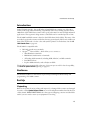
1. Insert the cable into the receptacle on the bottom of the scanner, as shown below:
Figure 1-1. Installing the Cable
2. Twist the cable to the left to lock in place, as shown below:
Figure 1-2. Installing the Cable:Twistlock Mechanism
1-4
Introduction and Setup
Switching Cables
Different cables are required for different hosts. To change the scanner cable:
1. “Unlock” the cable by twisting to the right.
2. Pull the cable out of the receptacle on the bottom of the scanner.
Figure 1-3. Removing the Cable
3. Insert a new cable in the receptacle.
4. Twist to the left to lock the new cable in place.
Connecting to a Host
With some terminal types, the LS 100x is unable to answer host terminal polls until the
appropriate host type is selected. This may result in an error message generated by the host.
To correct this situation, select proper parameter values and initialize the host terminal. See
Chapter 4 for more information.
RS-232C
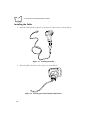
For external power operation with Synapse “Smart Cable”
1. Plug the Synapse adapter cable into the scanner .
2. Connect the Synapse “Smart Cable” with the host connector.
3. If required, connect the power supply to the input receptacle located on the Synapse
cable.
1-5
LS 1004 Scanner Product Reference Guide
Figure 1-4. External Power Connection using Synapse Cable
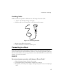
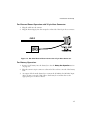
For RS-232C Operation External Power via Flying Lead Connector
1. Plug the cable into the scanner.
2. Plug the Power Supply into the receptacle on the Flying Lead connector.
Figure 1-5. RS-232C External Power Connection: Flying Lead Connector to a 9-pin
Host Connector
1-6
Introduction and Setup
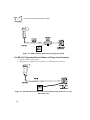
For External Power Operation with 25-pin Host Connector
1. Plug the cable into the scanner.
2. Plug the Power Supply into the receptacle on the side of the 25-pin host connector.
Figure 1-6. RS-232C External Power Connection: 25-pin Host Connector
For Battery Operation:
1. Insert a 9-volt battery into the battery box. See the Battery Box Operation section
on page 3-3.
2. Plug the scanner's 9-pin connector at the end of the cord into one end of the battery
box.
3. An output cable from the battery box connects the LS 1004 to the RS-232C input
device. Connect one end of this cable to the battery box and the other to the
appropriate port on the host device.
1-7
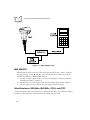
LS 1004 Scanner Product Reference Guide
Figure 1-7. RS-232C Operation
IBM 468X/9X
Plug the SDL modular connector at the end of the selected Synapse “Smart” cable into
the appropriate port (5B, 9B, 9C, 9E, or 17). Check that the connection is secure. To
install an LS 1004 on an IBM 468X/469X host:
1. Connect a synapse adapter cable to the scanner, using the procedure described in
“Installing the Cable” on page 1-4.
2. Plug the other end of the adaptor cable into the synapse cable’s female connector.
3. Scan the appropriate port address (see your Synapse Guide for details).
Wand Emulation, IBM 468x, IBM 469x, OCIA, and OCR
A Synapse Adapter Cable is required when connecting the LS 1004 to any of these hosts using
Synapse. See the instructions packed with the appropriate Synapse cable.
1-8
Chapter 2
Scanning
Chapter Contents
Introduction . . . . . . . . . . . . . . . . . . . . . . . . . . . . . . . . . . . . . . . . . . . . . . . . . . . . . . . . . . . . . . . . . 2-3
Scanning with the LS1004 . . . . . . . . . . . . . . . . . . . . . . . . . . . . . . . . . . . . . . . . . . . . . . . . . . . . . . . 2-3
Aiming . . . . . . . . . . . . . . . . . . . . . . . . . . . . . . . . . . . . . . . . . . . . . . . . . . . . . . . . . . . . . . . .. . . . . . 2-4
Scan the Entire Symbol . . . . . . . . . . . . . . . . . . . . . . . . . . . . . . . . . . . . . . . . . . . . . . . . . . . . . . 2-4
Hold at an Angle . . . . . . . . . . . . . . . . . . . . . . . . . . . . . . . . . . . . . . . . . . . . . . . . . . . . . . . . . . . 2-4
2-1
LS 1004 Product Reference Guide
2-2
Scanning
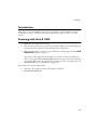
Introduction
This chapter covers the techniques involved in scanning bar codes. Included are specific
instructions on how to hold the scanner at the appropriate angle to ensure an accurate
decode.
Scanning with the LS 1004
1. Make sure all connections are secure.
2. Aim the scanner away from you and press the trigger. When you press the trigger, the
scanning beam is energized for approximately 1 second (default).
3. Make sure the symbol you want to scan is within the scanning range. See the LS 1004
Decode Zone diagram on page 3-6.
Aim and press the trigger. On the LS 1004, if you use the scanner in default Low
Power operating mode, the DECODE LED remains on until power down (maximum
of 1 second). If the unit is programmed for Continuous power operating mode, the
DECODE LED stays on until the next trigger pull.
The scanner has read the symbol when:
!
You hear a short, high tone beep (if the beeper is enabled).
!
The DECODE LED lights.
2-3
LS 1004 Product Reference Guide
Aiming
Scan the Entire Symbol
!
Your scan beam must cross every bar and space on the symbol.
!
The larger the symbol, the farther away you should hold the scanner.
!
Hold the scanner closer for symbols with bars that are close together.
!
A short, high tone beep indicates a good decode.
RIGHT
WRONG
012345
012345
Hold at an Angle
Do not hold the scanner directly over the bar code. Laser light reflecting directly back into
the scanner from the bar code is known as specular reflection. This strong light can “blind”
the scanner and make decoding difficult. The area where specular reflection occurs is known
as a “dead zone”.
2-4
Scanning
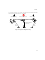
You can tilt the scanner up to 65° forward or back and achieve a successful decode. Simple
practice quickly shows what tolerances to work within.
1. Successful Scanning.
2. Possible Specular Reflection.
3. Successful Scanning.
65°
65°
Shaded area represents
dead zone (±2°)
Scan
Beam
Scan
Beam
Bar Code
Bar Code
Bar Code
Figure 2-1. Appropriate Angles for Scanning
2-5
LS 1004 Product Reference Guide
2-6
Chapter 3
Maintenance & Specifications
Chapter Contents
Introduction . . . . . . . . . . . . . . . . . . . . . . . . . . . . . . . . . . . . . . . . . . . . . . . . . . . . . . . . . . . . . . . . . 3-3
Maintaining the LS 1004 Scanner. . . . . . . . . . . . . . . . . . . . . . . . . . . . . . . . . . . . . . . . . . . . . . . . . . 3-3
Battery Box Operation . . . . . . . . . . . . . . . . . . . . . . . . . . . . . . . . . . . . . . . . . . . . . . . . . . . . . . 3-3
Maintenance. . . . . . . . . . . . . . . . . . . . . . . . . . . . . . . . . . . . . . . . . . . . . . . . . . . . . . . . . . . . . . . . . . 3-4
Accessories . . . . . . . . . . . . . . . . . . . . . . . . . . . . . . . . . . . . . . . . . . . . . . . . . . . . . . . . . . . . . . . . . . . 3-4
Required Accessories . . . . . . . . . . . . . . . . . . . . . . . . . . . . . . . . . . . . . . . . . . . . . . . . . . . . . . . . 3-4
Optional Accessories . . . . . . . . . . . . . . . . . . . . . . . . . . . . . . . . . . . . . . . . . . . . . . . . . . . . . . . . 3-4
What If... . . . . . . . . . . . . . . . . . . . . . . . . . . . . . . . . . . . . . . . . . . . . . . . . . . . . . . . . . . . . . . . . . . . . 3-5
LS 1004 Technical Specifications . . . . . . . . . . . . . . . . . . . . . . . . . . . . . . . . . . . . . . . . . . . . . . . . . . 3-6
LS 1004 Decode Zone . . . . . . . . . . . . . . . . . . . . . . . . . . . . . . . . . . . . . . . . . . . . . . . . . . . . . . . 3-6
3-1
LS 1004 Product Reference Guide
3-2
Maintenance and Specifications
Introduction
This chapter covers the suggested maintenance of the LS 1004 scanner, as well as the technical
specifications, available accessories, pinouts, and beeper definitions.
Maintaining the LS 1004 Scanner
Battery Box Operation
When using the LS 1000 Series with a battery box, you can use either an alkaline battery
(recommended), or a nickel-cadmium rechargeable battery. Low power is signalled by 4
short, high-tone beeps, coupled with scanning interruptions. If this occurs, change or
recharge the battery as soon as possible. For battery box operation:
1. Insert a 9-volt battery into the battery box.
2. Plug the scanner’s 9-pin connector at the end of the coil cord into the end of the
battery box.
3. An output cable from the battery box connects the LS 1004 to the host device.
Connect one end of this cable to the battery box and the other to the appropriate
port on the host device.
Note: Not all applications require a power supply or battery box. The
output cable depends on the wand being replaced.
Changing the Battery
1. Disconnect the battery box.
2. To open the battery box, push up on the flanges at one end of the pack.
3. Remove the old battery.
4. Insert the new or recharged 9-volt battery into the battery box. Match the
positive (+) and negative (-) terminals on the battery with the corresponding
terminals in the battery box.
3-3
LS 1004 Product Reference Guide
Recharging a Nickel-Cadmium Battery
!
Remove the battery from the battery box and place it in the recharging unit (not
supplied by Symbol).
!
To recharge the battery, follow the instructions supplied with the recharging unit.
Maintenance
Cleaning the exit window is the only maintenance required.
!
Do not allow any abrasive material to touch the window.
!
Remove any dirt particles with a damp cloth.
!
Wipe the window using a damp cloth, and if necessary, a non-ammonia based
detergent.
!
Do not spray water or other cleaning liquids directly into the window.
Accessories
Required Accessories
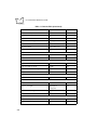
Required accessories are listed below. Optional accessories are available at extra cost.
Table 3-1. LS 1004 Required Accessories
Part Number
Description
ND1222
Synapse Adapter Cable
ND1223
One RS-232 Cable 9-pin female TxD pin 2, or
ND1224
One RS-232 Cable 25-pin male TxD pin 3, or
ND1225
One RS-232 Cable 25-pin TxD pin 3
70-17422-01
LS 1000 Series Quick Reference Guide
Optional Accessories
Optional accessories include various stands and holders, which are supplied at extra cost.
Additional units of standard accessories may also be purchased at extra cost.
3-4
Maintenance and Specifications
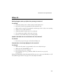
What If...
Nothing happens when you follow the operating instructions?
You Should
!
Check the system power; is there a battery in the battery box?
!
Be sure the scanner is programmed for the terminal in use.
!
Make sure the scanner is programmed to read the type of bar code you are scanning.
!
Check for loose cable connections.
!
Check the symbol to make sure it is not defaced.
!
Try scanning test symbols of the same code type.
!
Be sure you are within the proper scanning range.
Symbol is decoded, but not transmitted to the host terminal?
You Should
!
Be sure the proper host type is selected (See Chapter 4).
Scanned data is incorrectly displayed on the terminal?
You Should
!
Make sure the system is programmed for the correct keyboard type.
!
Make sure the CAPS LOCK key is off.
!
Be sure the proper host is selected.
!
Be sure editing options (e.g., UPC-E to UPC-A Conversion) are properly
programmed.
If after performing these checks the symbol still does not scan, contact your distributor or call
the Symbol Support Center. See page viii for the telephone number.
3-5
LS 1004 Product Reference Guide
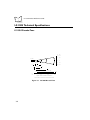
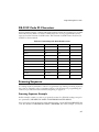
LS 1004 Technical Specifications
LS 1004 Decode Zone
In.
Cm.
10
25.4
5
12.7
0
0
5
12.7
Scanner
5.0 mil
1.0
2.3
10
7.5 mil
5.0
0
13 mil
2.0
In.
Cm.
0
0
9.0
20 mil minimum element width
5
12.7
10
25.4
15.0
15
38.1
Depth of Field in Inches/Centimeters
Depth of field as a function of minimum element width.
Figure 3-1. LS 1004 Decode Zone
3-6
25.4
Maintenance and Specifications
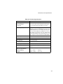
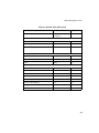
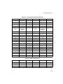
Table 3-2.Technical Specifications
Item
Power Requirements*
RS-232C/Synapse
Low Power
Description
4.75 to 14.5 VDC (max) 100mA @ 5VDC typical
4.75 to 14 VDC (max) 200 mA @ 5V typical
Decode Capability
The LS 1004 can be programmed to decode the
following code types: UPC/EAN, Code 39, Code
39 Full ASCII, Code 93, Codabar, Interleaved 2
of 5, Code 128, EAN 128, and Discrete 2 of 5. Set
code length(s) for any linear code type. The LS 1004
can auto-discriminate between all of the above code
types except for Code 39 and Code 39 Full ASCII.
Beeper Operation
User-selectable: Enabled, Disabled, Volume, Tone
Scan Repetition Rate
36 (± 3) scans/sec (bidirectional)
Skew Tolerance
± 65° from normal
Pitch
± 60° from normal
Decode Depth of Field
See Decode Zone
Print Contrast Minimum
25% absolute dark/light differential, measured at
670 nm.
Ambient Light Immunity
Artificial Lighting
Sunlight
450 ft. candles
8000 ft. candles
4844 lux
86112 lux
3-7
LS 1004 Product Reference Guide
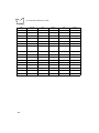
Table 3-2.Technical Specifications (Continued)
Item
Description
Operating Temperature
32° to 104°F0° to 40°C
Storage Temperature
-40° to 140°F-40° to 60°C
Humidity
5% to 95% (non-condensing)
Durability
4-ft. drop to concrete1.2 m
Dimensions
Height
Length
Width
4.8 in.122 mm
3.7 in.93 mm
2.4 in.60 mm
Laser Classifications
CDRH Class II
IEC 825 Class 2
Start-Up Time
<50 msec from scan enable
Data Acquisition Time
<110 msec from scan enable
Minimum Element Width
0.005 in0.127 mm
Maximum Element Width
0.020 in5.08 mm
*For direct host power connection, make sure the host terminal supplies sufficient power for
the specified operation. Symbol is not responsible for damage to host equipment or system
mis-operation due to an insufficient power condition.
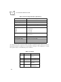
Table 3-3. Pinouts
Pin
3-8
LS 1004
Function
1
Data
Data Line (for
synapse)
2
VBAT
Power Supply
3
GND
Ground
4
RTS
Request to Send (for
RS-232C)
5
RXD*
Receive Data Input
(for RS-232C)
Maintenance and Specifications
Table 3-3. Pinouts (Continued)
Pin
LS 1004
Function
6
N.C.
Non-Connected (for
RS-232C)
7
DTR
Data Terminal Ready
(for RS-232C)
8
TXD*
Transmit Data
Output (for RS232C)
9
CTS
Clear to Send (for RS232C)
10
Clock
Clock Line (for
Synapse)
* active low
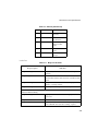
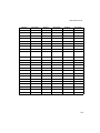
Table 3-4. Beeper Indications
Standard Use
Beeper Sequence
Indication
1 Beep - short high tone
A bar code symbol was decoded (if decode beeper is
enabled).
4 Beeps - long low tone
A transmission error has been detected in a scanned
symbol. The last data scanned was lost. Scan the last data
again.
4 Beeps - short high tone
Low power indication; no further scanning is possible.
Change or recharge battery.
3 Beeps - short high tone
Power-up (continuous power mode only)
Parameter Menu Scanning
1 Beep - short high tone
Appropriate menu within the scanning sequence has
been read
1 Beep - warble sound
Parameter value entered successfully
2 Beeps - long low tone
Parameter not entered, or incorrect sequence performed.
Scan CANCEL and restart the scanning sequence.
3-9
LS 1004 Product Reference Guide
3-10
Chapter 4
Programming The LS 1004
Chapter Contents
Introduction . . . . . . . . . . . . . . . . . . . . . . . . . . . . . . . . . . . . . . . . . . . . . . . . . . . . . . . . . . . . . . . . . 4-3
RS-232 Host Type Defaults . . . . . . . . . . . . . . . . . . . . . . . . . . . . . . . . . . . . . . . . . . . . . . . . . . . . . . 4-6
RS-232C Code ID Characters. . . . . . . . . . . . . . . . . . . . . . . . . . . . . . . . . . . . . . . . . . . . . . . . . . . . . 4-7
Scanning Sequence . . . . . . . . . . . . . . . . . . . . . . . . . . . . . . . . . . . . . . . . . . . . . . . . . . . . . . . . . . . . . 4-7
Scanning Sequence Example . . . . . . . . . . . . . . . . . . . . . . . . . . . . . . . . . . . . . . . . . . . . . . . . . . 4-7
Errors While Scanning. . . . . . . . . . . . . . . . . . . . . . . . . . . . . . . . . . . . . . . . . . . . . . . . . . . . . . . 4-8
Parameter Descriptions. . . . . . . . . . . . . . . . . . . . . . . . . . . . . . . . . . . . . . . . . . . . . . . . . . . . . . . . . . 4-9
Set Parameter Defaults . . . . . . . . . . . . . . . . . . . . . . . . . . . . . . . . . . . . . . . . . . . . . . . . . . . . . . 4-9
Host Interface Select . . . . . . . . . . . . . . . . . . . . . . . . . . . . . . . . . . . . . . . . . . . . . . . . . . . . . . . . 4-9
RS-232 Host Type . . . . . . . . . . . . . . . . . . . . . . . . . . . . . . . . . . . . . . . . . . . . . . . . . . . . . . . . . . . . 4-10
Power On Beep Enable/Disable . . . . . . . . . . . . . . . . . . . . . . . . . . . . . . . . . . . . . . . . . . . . . . . 4-11
Beeper after Decode. . . . . . . . . . . . . . . . . . . . . . . . . . . . . . . . . . . . . . . . . . . . . . . . . . . . . . . . 4-11
Beeper Tone . . . . . . . . . . . . . . . . . . . . . . . . . . . . . . . . . . . . . . . . . . . . . . . . . . . . . . . . . . . . . 4-12
Beeper Volume . . . . . . . . . . . . . . . . . . . . . . . . . . . . . . . . . . . . . . . . . . . . . . . . . . . . . . . . . . . 4-12
Decode Attempt Time . . . . . . . . . . . . . . . . . . . . . . . . . . . . . . . . . . . . . . . . . . . . . . . . . . . . . . 4-13
Operating Mode . . . . . . . . . . . . . . . . . . . . . . . . . . . . . . . . . . . . . . . . . . . . . . . . . . . . . . . . . . 4-14
Aggressive Scan Mode . . . . . . . . . . . . . . . . . . . . . . . . . . . . . . . . . . . . . . . . . . . . . . . . . . . . . . 4-14
Transmit “No Decode” Message. . . . . . . . . . . . . . . . . . . . . . . . . . . . . . . . . . . . . . . . . . . . . . 4-15
Decode Redundancy . . . . . . . . . . . . . . . . . . . . . . . . . . . . . . . . . . . . . . . . . . . . . . . . . . . . . . . 4-15
Code Types . . . . . . . . . . . . . . . . . . . . . . . . . . . . . . . . . . . . . . . . . . . . . . . . . . . . . . . . . . . . . . 4-15
UPC/EAN . . . . . . . . . . . . . . . . . . . . . . . . . . . . . . . . . . . . . . . . . . . . . . . . . . . . . . . . . . . . . . . 4-17
Code 128 . . . . . . . . . . . . . . . . . . . . . . . . . . . . . . . . . . . . . . . . . . . . . . . . . . . . . . . . . . . . . . . 4-22
Code 39 . . . . . . . . . . . . . . . . . . . . . . . . . . . . . . . . . . . . . . . . . . . . . . . . . . . . . . . . . . . . . . . . 4-23
Code 93 . . . . . . . . . . . . . . . . . . . . . . . . . . . . . . . . . . . . . . . . . . . . . . . . . . . . . . . . . . . . . . . . 4-24
Interleaved 2 of 5 . . . . . . . . . . . . . . . . . . . . . . . . . . . . . . . . . . . . . . . . . . . . . . . . . . . . . . . . . 4-24
Discrete 2 of 5 . . . . . . . . . . . . . . . . . . . . . . . . . . . . . . . . . . . . . . . . . . . . . . . . . . . . . . . . . . . . 4-27
4-1
LS 1004 Product Reference Guide
Codabar . . . . . . . . . . . . . . . . . . . . . . . . . . . . . . . . . . . . . . . . . . . . . . . . . . . . . . . . . . . . . . . . . 4-29
Data Options . . . . . . . . . . . . . . . . . . . . . . . . . . . . . . . . . . . . . . . . . . . . . . . . . . . . . . . . . . . . . 4-30
RS-232C. . . . . . . . . . . . . . . . . . . . . . . . . . . . . . . . . . . . . . . . . . . . . . . . . . . . . . . . . . . . . . . . . 4-34
4-2
Programming the LS 1004
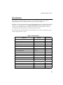
Introduction
This chapter provides information on how to program the LS 1004 scanner. Before
programming the scanner, follow the instructions in Set-Up on page 1-3.
The Table 4-1 illustrates the default values with which the scanner is shipped. If the default
values suit your requirements, scan the SET ALL DEFAULTS barcode. This will set the
scanner to the default parameters. Changing the scanner’s programmable parameters is
accomplished by scanning the bar codes provided in this section.
The following table lists the defaults for all parameters. If you wish to change any option,
scan the appropriate bar code(s).
Table 4-1. Default Table
Parameter
Default
Page Number
Set Default Parameter
All Defaults
4-9
Host Interface Select
RS-232C
4-9
Power On Beep
Disable
4-11
Beep after Decode
Enable
4-11
Beeper Tone
Middle
4-12
Beeper Volume
High Level
4-12
Decode Attempt Time
1 second
4-13
Operating Mode
Low Power
4-14
Aggressive Scan Mode
Disable
4-14
Transmit “No Decode” message
No Message
4-15
Decode Redundancy
Disable
4-15
Code Types
All
4-16
Enable/Disable UPC/EAN
Enable
4-17
Transmit UPC-A Check Digit
Enable
4-17
Transmit UPC-E Check Digit
Enable
4-17
UPC/EAN
4-3
LS 1004 Product Reference Guide
Table 4-1. Default Table (Continued)
Parameter
Default
Page Number
Decode UPC Only
Disable
4-17
Convert UPC-E to UPC-A
Disable
4-18
EAN Zero Extend
Disable
4-18
Decode UPC/EAN Supplemental
No Supplemental
4-19
UPC-E Preamble
System Character
4-20
UPC-A Preamble
System Character
4-20
UPC/EAN Security Level
Level 0
4-21
Enable/Disable Code 128
Enable
4-22
Send Code 128 Function Character
Disable
4-22
Enable/Disable Code 39
Enable
4-23
Code 39 modulo 43 check
Disable
4-23
Transmit Code 39 Check Digit
Disable
4-23
Enable/Disable Code 39 Full ASCII
Enable
4-24
Enable
4-24
Enable/Disable Code I 2 of 5
Enable
4-24
Set I 2 of 5 Lengths
14 (length 1)
0 (length 2)
4-24
Modulo 10 Check Digit
Disable
4-26
ITF14/EAN13 Conversion
Disable
4-26
Enable/Disable Code D 2 of 5
Enable
4-27
Modulo 10 Check Digit
Disable
4-27
Code 128
Code 39
Code 93
Enable/Disable Code 93
I 2 of 5
D 2 of 5
4-4
Programming the LS 1004
Table 4-1. Default Table (Continued)
Parameter
Set D 2 of 5 Lengths
Default
Page Number
12 (length 1)
0 (length 2)
4-27
Enable/Disable Codabar
Enable
4-29
CLSI Editing
Disable
4-29
NOTIS Editing
Disable
4-29
Transmit Code ID Character
Disable
4-30
Prefix
None
4-31
Suffix
CR/LF
4-31
Baud Rate
9600
4-34
Parity
Even
4-35
Data Format
7 Data Bits (with Parity)
4-36
Stop Bit Select
Two
4-36
Check Parity of Received Data
Enable
4-36
Hardware Handshaking
None
4-37
Software Handshaking
None
4-37
Intercharacter Delay
0msec
4-41
Codabar
Data Options
RS-232C
4-5
LS 1004 Product Reference Guide
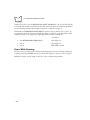
RS-232 Host Type Defaults
Three RS-232C hosts are set up with their own parameter default settings (See Table 4-2.).
Selecting the ICL, Fujitsu, or Nixdorf RS-232C terminal sets the defaults listed below. These
defaults take precedence over standard defaults. So if you select Fujitsu RS-232C, then select
the standard defaults, the Fujitsu defaults still take precedence.
Table 4-2.Terminal-Specific RS-232C Defaults
Parameter
Standard
ICL
FUJITSU
NIXDORF
Mode A/
Mode B
Transmit Code ID
No
Yes
Yes
Yes
Data Transmission Format
Data as is
Data/Suffix
Data/Suffix
Data/Suffix
Suffix
CR/LF (7013)
CR (1013)
CR (1013)
CR (1013)
Baud Rate
9600
9600
9600
9600
Parity
None
Even
None
Odd
Hardware Handshaking
None
RTS/CTS
Option 3
None
RTS/CTS
Option 3
Software Handshaking
None
None
None
None
Serial Response Time-out
2 Sec.
9.9 Sec.
2 Sec.
9.9 Sec.
Stop Bit Select
One
One
One
One
ASCII Format
8-Bit
8-Bit
8-Bit
8-Bit
Beep On <BEL>
Disabled
Disabled
Disabled
Disabled
RTS Line State
Low
High
Low
*Low = No
data to send
*In the Nixdorf Mode B, if CTS is Low, scanning is disabled. When CTS is High, the user can scan
bar codes.
4-6
Programming the LS 1004
RS-232C Code ID Characters
Selecting the ICL, Fujitsu, or Nixdorf RS-232C terminal enables the transmission of Code ID
Characters listed in Table 4-3. These Code ID Characters are not programmable and are
separate from the Transmit Code ID feature. The Transmit Code ID feature should not be
enabled for these terminals.
Table 4-3.Terminal Specific Code ID Characters
ICL
FUJITSU
NIXDORF
UPC-A
“A”
“A”
“A”
UPC-E
“E”
“E”
“C0”
EAN-8
“FF”
“FF”
“B”
EAN-13
“F”
“F”
“A”
Code 39
“C” <len>
None
“M”
Codabar
“N” <len>
None
“N”
Code 128
“L” <len>
None
“K”
I 2 of 5
“I” <len>
None
“I”
Code 93
None
None
“L”
D 2 of 5
“H” <len>
None
“H”
UCC/EAN 128
“L” <len>
None
“P”
Scanning Sequence
A scanning sequence establishes a value for one parameter type. During a scanning sequence,
bar codes are scanned to select a parameter. All bar codes necessary for programming the
scanner are provided in Parameter Menus, beginning on page 4-9.
Scanning Sequence Example
In this example, assume you want to program the scanner for all default settings except for
two parameters, DECODE UPC ONLY and INTERCHARACTER DELAY.
Since you want to keep the majority of the default settings, scan the SET ALL DEFAULTS bar
code. The default for DECODE UPC ONLY is DISABLED, but in this example, you need it
4-7
LS 1004 Product Reference Guide
enabled. To do this, scan the DECODE UPC ONLY ENABLE bar code. You’ll hear hi/lo/hi/
low warble. The warble sound indicates that the scanner has been successfully programmed
for the selected parameter. Other beeper indications are listed in Chapter 3.
The default for INTERCHARACTER DELAY is 0 msec, but you need it set to 2 msec. To
program the scanner for a 2msec intercharacter delay, scan the bar codes listed below. This
sequence includes a two-digit entry; single-digit entries require a leading zero.
You’ll hear...
1. Scan INTERCHARACTER DELAY
Short high tone
2. Scan 0
Short high tone
3. Scan 2
Hi/Lo/Hi/Lo warble
Errors While Scanning
Don’t worry if you make an error during a scanning sequence. If you’re scanning a multi-step
sequence, scanning CANCEL removes you from that sequence so that you can start again.
Otherwise, simply scan the single correct bar code for the desired parameter.
4-8
Programming the LS 1004
Parameter Menus
Refer to the Default table in the front of this chapter for the default settings for each
parameter type.
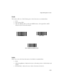
Set Parameter Defaults
Scanning the SET ALL DEFAULTS bar code returns all parameters to the default values listed
in the Default Table.
Set All Defaults
Host Interface Select
Scan the bar code corresponding to your host type. You must select a host type when you first
set up the scanner and whenever you change host type.
Set RS-232C Host
Set Synapse Host
4-9
LS 1004 Product Reference Guide
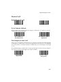
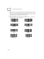
RS-232 Host Type
Use this option to select an RS-232 host type. Note: Synapse hosts are autodetected; no bar
codes need to be scanned for hosts using Synapse.
1. Scan the bar code corresponding to the desired host type.
2. Scan ENTER.
Standard RS-232 Host Type
ICL Host Type
Fujitsu Host Type
Nixdorf Mode A Host Type
Nixdorf Mode B Host Type
4-10
Programming the LS 1004
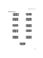
Power On Beep Enable/Disable
This option, if selected, causes the beeper to sound at power-up (in continuous power mode
only).
Power On Beep Enable
Power On Beep Disable
Beeper after Decode
This option determines whether the beeper sounds during normal scanning. Usually, it is
desirable to operate the unit with the beeper enabled. In all cases, the beeper operates during
parameter menu scanning and indicates error conditions. See Table 3-4 on page 3-9.
Beeper Enable
Beeper Disable
4-11
LS 1004 Product Reference Guide
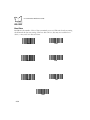
Beeper Tone
Three options are available for beeper tone (frequency); low, middle, and high.
Beeper Tone Low
Beeper Tone Middle
Beeper Tone High
Beeper Volume
Three options are available for beeper volume; low, middle, and high.
Beeper Volume Low
Beeper Volume Middle
Beeper Volume High
4-12
Programming the LS 1004
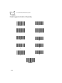
Decode Attempt Time
This parameter sets the length of time the scanner laser beam remains on while attempting to
scan a symbol.
0.5 seconds
3.5 seconds
1.0 seconds
4.0 seconds
1.5 seconds
4.5 seconds
2.0 seconds
5.0 seconds
2.5 seconds
5.5 seconds
3.0 seconds
6.0 seconds
4-13
LS 1004 Product Reference Guide
Decode Attempt Time (cont’d)
6.5 seconds
7.0 seconds
Operating Mode
This parameter determines whether or not power remains on after a decode attempt. The
LOW POWER option provides for power-down after each scan attempt, while the
CONTINUOUS option provides for power to remain on after each scan attempt.
Continuous
Low Power
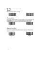
Aggressive Scan Mode
This parameter is available in the continuous operation mode only. When you set this
parameter to be enabled, the scanner scans the mirror continuously, even if it does not
illuminate the laser diode.
Aggressive Scan
Enable
4-14
Aggressive Scan
Disable
Programming the LS 1004
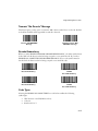
Transmit “No Decode” Message
This feature gives you the option to transmit “NR” when a symbol does not decode. Prefixes
and suffixes enabled will be appended around this character.
Transmit “NO DECODE”
Message
Do Not Transmit “NO
DECODE” Message
Decode Redundancy
When you select ENABLE CODABAR DECODE REDUNDANCY, a Codabar symbol must
be decoded in both directions before being accepted as a successful decode. If you select
ENABLE ALL CODE TYPES DECODE REDUNDANCY, all bar code symbols must be
decoded in both directions before being accepted as successful decodes.
Enable CODABAR
Decode Redundancy
Enable ALL CODE
TYPES
Decode Redundancy
Disable CODABAR
Decode Redundancy
Disable ALL CODE
TYPES
Decode Redundancy
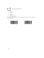
Code Types
Selecting the ENABLE ALL CODE TYPES bar code below enables the following
symbologies:
!
UPC Versions A and E (EAN 8 and 13)
!
Code 39
!
Interleaved 2 of 5
4-15
LS 1004 Product Reference Guide
!
Code 93
!
Codabar
!
Discrete 2 of 5
!
Code 128
!
Code 39 Full ASCII
The scanner autodiscriminates between all of the above symbologies, except for Code 39 and
Code 39 Full ASCII.
Enable All Code Types
4-16
Disable All Code Types
Programming the LS 1004
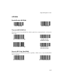
UPC/EAN
Enable/Disable UPC/EAN
Enable UPC/EAN
Disable UPC/EAN
Transmit UPC-E/UPC-A
Select this option if decoded UPC-E or UPC-A symbols are transmitted with or without the
check digit.
Transmit UPC-A check digit
Do Not Transmit
UPC-A Check Digit
Transmit UPC-E check digit
Do Not Transmit
UPC-E Check Digit
Decode UPC Only (Not EAN)
If selected, this option limits the scanner’s capability to UPC versions only. It disables EAN
decode capability.
Decode UPC Only Enable
Decode UPC Only Disable
4-17
LS 1004 Product Reference Guide
Convert UPC-E to UPC-A
Select this option to convert UPC-E (zero suppressed) decode data to UPC-A format before
transmission. After conversion, data follows UPC-A format and is affected by UPC-A
programming selections (e.g., Preamble, Check Digit).
Convert UPC-E to
UPC-A
Do Not Convert
UPC-E to UPC-A
EAN Zero Extend
This parameter adds five leading zeros to decoded EAN-8 symbols to make them compatible
in format to EAN-13 symbols.
Enable EAN Zero
Extend
4-18
Disable EAN Zero
Extend
Programming the LS 1004
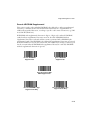
Decode UPC/EAN Supplemental
This option is used to select whether UPC/EAN is decoded with or without supplemental
characters, or whether the unit autodiscriminates between the two. Supplementals are
additionally appended characters, according to specific code format conventions (e.g., UPC
A+2, UPC E+2, EAN 8+5).
If UPC/EAN with supplemental characters 2-digit or 5-digit only is selected, UPC/EAN
symbols without supplemental characters won’t be decoded. If UPC/EAN without
supplemental characters is selected and the scanner is presented with a UPC/EAN plus
supplemental symbol, the UPC/EAN is decoded and the supplemental characters are ignored.
If autodiscrimination is chosen, the scanner will, after additional processing to ensure a good
decode, transmit either. If UPC/EAN with supplemental characters is selected, UPC/EAN
without supplemental characters is ignored.
Decode UPC/EAN
Supplementals
Ignore UPC/EAN
Supplementals
Autodiscriminate UPC/
EAN Supplementals
Decode UPC/EAN 2-digit
Supplementals Only
Decode UPC/EAN 5-digit
Supplementals Only
4-19
LS 1004 Product Reference Guide
UPC A and E Preamble(s)
Three options are available for the lead-in characters for decoded UPC-A or UPC-E symbols
transmitted to the host device. Select one preamble for UPC-A decodes and one for UPC-E
decodes. These lead-in characters are considered part of the symbol itself. The three options
are:
!
a system character only
!
the country code and system character
!
no preamble
The system character is the digit printed to the extreme left of a UPC symbol. The country
code for UPC is always zero, and it cannot be transmitted without the system character.
UPC-A Preambles
UPC-E Preambles
None
None
System Character
System Character
System Character
and
Country Code
4-20
System Character
and
Country Code
Programming the LS 1004
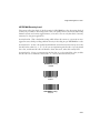
UPC/EAN Security Level
The scanner offers four levels of decode security for UPC/EAN bar codes. Increasing levels of
security are provided for decreasing levels of bar code quality. There is an inverse relationship
between security and scanner aggressiveness, so be sure to choose only that level of security
necessary for any given application.
Security Level 0 - This is the default setting which allows the scanner to operate in its most
aggressive state, while providing sufficient security in decoding in spec UPC/EAN bar codes.
Security Level 1 - As bar code quality levels diminish, certain characters become prone to misdecodes before others (i.e., 1, 2, 7, 8). If you are experiencing mis-decodes of poorly printed
bar codes, and the mis-decodes are limited to these characters, select this security level.
Security Level 2 - If you are experiencing mis-decodes on poorly printed bar codes, and the
mis-decodes are not limited to characters 1, 2, 7 and 8, select this security level.
UPC/EAN Security
Level 0
UPC/EAN Security
Level 1
UPC/EAN Security
Level 2
4-21
LS 1004 Product Reference Guide
Code 128
Enable/Disable Code 128
Enable Code 128
Disable Code 128
Send Code 128 Function Character
If selected, Code 128 function characters are sent as:
!
FN1=0X1D
!
FN2=0X81
!
FN3=0X82
!
FN4=0X83
This option is enabled when data format is 8 bits. Even if this option is disabled or data
format is 7 bits, FN1 is still set as 0X1D, unless FN1 is in the first or second character in a
bar code message.
Transmit Code 128
Function Character
Enabled
4-22
Transmit Code 128
Function Character
Disabled
Programming the LS 1004
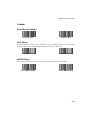
Code 39
Enable/Disable Code 39
Enable Code 39
Disable Code 39
Code 39 Modulo 43 Check
When enabled, this parameter checks the integrity of a Code 39 symbol to ensure it complies
with specified algorithms.
Verify Code 39
Check Digit
Do Not Verify Code
39 Check Digit
Transmit Code 39 Check Digit
When enabled, Code 39 Check Digit will be sent to the host.
Transmit Code 39
Check Digit Enable
Transmit Code 39
Check Digit Disable
4-23
LS 1004 Product Reference Guide
Enable/Disable Code 39 Full ASCII
Enable Code 39
Full ASCII
Disable Code 39
Full ASCII
Code 93
Enable/Disable Code 93
Enable Code 93
Disable Code 93
Interleaved 2 of 5
Enable/Disable Code I 2 of 5
Enable Code I 2 of 5
Disable Code I 2 of 5
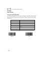
Fixed Lengths for Code I 2 of 5
Select one or two lengths for the Interleaved 2 of 5 codes. If you set both Length 1 and Length
2 to 0, the scanner can read any length within 36 characters. It is recommended that you set
the I 2 of 5 modulus 10 check to enabled when you set both Length 1 and Length 2 to 0.
If any default setting is in effect and is an appropriate length, it need not be reset. Length 1
may range from 00-36 and Length 2 may range from 00-36.
I 2 of 5 Length 1
(Range 00-36)
4-24
I 2 OF 5 Length 2
(Range 00-36)
Programming the LS 1004
Fixed Lengths for Code 2 of 5 (cont’d)
0
1
2
3
4
5
7
6
9
8
Cancel
4-25
LS 1004 Product Reference Guide
I 2 of 5 Modulo 10 Check
When enabled, this parameter checks the integrity of an Interleaved 2 of 5 symbol to ensure
it complies with specific algorithms.
I 2of 5 Modulo 10
Check Digit Enable
I 2of 5 Modulo 10
Check Digit Disable
ITF-14/EAN-13 Conversion
This feature converts a 14-character I 2 of 5 code into EAN-13, and transmits to the host as
EAN-13. In order to accomplish this, the I 2 of 5 code must be enabled, one length (either
LENGTH 1 or LENGTH 2) must be set to 14, the code must have a leading zero and proper
trailing check digit.
ITF-14/EAN-13
Conversion Enable
4-26
ITF-14/EAN-13
Conversion Disable
Programming the LS 1004
Discrete 2 of 5
Enable/Disable D 2 of 5
Enable Code D 2 of 5
Disable Code D 2 of
D 2 of 5 Modulo 10 Check
When enabled, this parameter checks the integrity of a Discrete 2 of 5 symbol to ensure it
complies with specific algorithms.
D 2 of 5 Modulo 10
Check Digit Enable
D 2 of 5 Modulo 10 Check
Digit Disable
Fixed Lengths for Code 2 of 5
Select one or two lengths for the Discrete 2 of 5 codes. If you set the both of them (Length 1
and Length 2) to 0, the scanner can read any length within 36 characters. It is recommended
that you set the D 2 of 5 modulus 10 check to enabled when you set both Length 1 and Length
2 to 0.
If any default setting is in effect and is an appropriate length, it need not be reset. Length 1
may range from 00-36 and Length 2 may range from 00-36
D 2 of 5 Length 1
(Range 00-36)
D 2 OF 5 Length 2
(Range 00-36)
4-27
LS 1004 Product Reference Guide
Fixed Lengths for Code 2 of 5 (cont’d)
0
1
2
3
4
5
7
6
9
8
CANCEL
4-28
Programming the LS 1004
Codabar
Enable/Disable Codabar
Enable Codabar
Disable Codabar
CLSI Editing
Use this parameter to insert a space after the 1st, 5th, and 10th characters of a 14-character
Codabar symbol. This symbol length includes start and stop characters.
Enable CLSI Editing
Disable CLSI Editing
NOTIS Editing
This option strips the start and stop characters from decoded Codabar symbols.
Enable NOTIS Editing
Disable NOTIS Editing
4-29
LS 1004 Product Reference Guide
Data Options
Transmit Code ID Character
A code ID character identifies the code type of a scanned bar code. This may be useful when
the scanner is decoding more than one code type. In addition to any single-character prefixes
already selected, the code ID character is appended as a prefix to the decode. The code ID
characters are:
ID Character
A
UPC-A, UPC-E, EAN-13, EAN-8
B
Code 39
C
Codabar
D
Code 128
E
Code 93
F
Interleaved 2 of 5
G
Discrete 2 of 5 or Discrete 2 of 5 IATA
Transmit Code ID
Character
4-30
Meaning
Do Not Transmit Code
ID
Programming the LS 1004
Prefix
The scanner adds one of the following start-of-text characters to transmitted data.
!
None
!
Start-of-text (STX)
!
One user-defined prefix (can be any ASCII character). See Appendix A, ASCII
Character Set for more information.
Prefix STX
Prefix None
User’s Choice Prefix Character
Suffix
Select one or two end-of-text characters to be added to transmitted data.
!
None
!
CR (Carriage Return) - Returns the cursor to the same position on the line after each
decode.
!
LF (Line Feed) - Moves the cursor down a line after each decode.
4-31
LS 1004 Product Reference Guide
!
CR & LF - Allow you to select where the cursor on a display terminal returns to after
it displays each decoded symbol. Selecting both CR and LF returns the cursor to the
same position on successive lines after each decode. If you select no control code, the
cursor remains where it stopped after the last transmission.
!
HT (Horizontal Tab) - Moves the cursor one tab space.
!
End -of-text <ETX> - One or two characters, user-defined. Refer to Appendix A,
ASCII Character Set for more information.
Suffix None
Suffix ETX
Suffix CR
Suffix CR/LF
Suffix LF
Suffix HT
User’s Choice Suffix
Character 1
4-32
User’s Choice Suffix
Character 2
Programming the LS 1004
Prefix/Suffix Values
0
1
2
3
4
5
6
7
9
8
Cancel
4-33
LS 1004 Product Reference Guide
RS-232C
Baud Rate
Baud Rate is the number of bits of data transmitted per second. The unit’s baud rate setting
should match the data rate setting of the host device. If not, data may not reach the host
device, or may reach it in distorted form.
2400
300
4800
600
1200
9600
19200
4-34
Programming the LS 1004
Parity
A parity check bit is the most significant bit of each ASCII coded character. If you select ODD
parity, the parity bit will have a value of 0 or 1, based on data, to ensure that an odd number
of 1 bits are contained in the coded character.
If you select EVEN parity, the parity bit will have a value, 0 or 1, to ensure that and even
number of 1 bits are contained in the coded character.
If you select MARK parity, the parity bit will always be 1.
If you select SPACE parity, the parity bit will always be 0.
Select the parity type according to the host device requirements.
Odd
Even
Space
Mark
None
4-35
LS 1004 Product Reference Guide
Data Format
This parameter sets the transmit data format. The options are:
!
7 Data Bits (With Parity) (default)
!
8 Data Bits (With Parity)
!
8 Data Bits (Without Parity)
7-Bit
8-Bit
Stop Bit Select
The stop bit(s) at the end of each transmitted character marks the end of transmission of one
character and prepares the receiving device for the next character in the serial data stream.
The number of stop bits (one or two) selected depends on the number the receiving terminal
is programmed to accommodate. Set the number of stop bits to match host device
requirements.
1 Stop Bit
2 Stop Bits
Check Parity
This option determines whether the parity of received characters is checked. The type of
parity used is selectable through the PARITY parameter.
Check Parity of Receive
Data Enable
4-36
Check Parity of Receive
Data Disable
Programming the LS 1004
Hardware Handshaking
Hardware handshaking allows you to check the readiness of the receiving device before data
is transmitted. If the receiving device is periodically occupied with other tasks, hardware
handshaking is needed to prevent loss of transmitted data.
Select whether the scanned data is to be transmitted as soon as it is available or whether
transmission should follow the RTS/CTS procedure.
None
RTS/CTS
Software Handshaking
This parameter offers control of the data transmission process in addition to, or instead of,
that offered by hardware handshaking. These options may be combined; for example, ACK/
NAK with ENQ.
!
No software handshaking
None
!
ACK/NAK only
The ACK/NAK option checks the success or failure of transmission. The scanner
expects one of the following host responses after a data transmission:
<ACK> acknowledges a valid and successful transmission.
<NAK> indicates a problem with the transmission.
Whenever a NAK is received, the unit retransmits the same data and awaits an ACK/
NAK response. After three unsuccessful attempts to transmit the same data, the
scanner aborts any further communication attempts of that message.
ACK/NAK
4-37
LS 1004 Product Reference Guide
!
ENQ ONLY
The ENQ option needs the host to request data before it is transmitted to the host.
This ensures that data transmission occurs only when the host is ready to receive.
When you select the wait for ENQ option, the scanner waits for an ENQ from the
host before it transmits data; otherwise, the unit transmits data without waiting for
an ENQ character from the host. With ENQ enabled, the scanner must receive an
ENQ from the host within a 2-second period after the last activity, or a transmission
error occurs.
ENQ Only
!
ACK/NAK with ENQ
This option combines both handshaking options.
ACK/NAK with ENQ
4-38
Programming the LS 1004
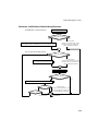
Hardware and Software Handshaking Sequence
HARDWARE HANDSHAKING
SYMBOL IS DECODED
RTS AND CTS
HANDSHAKING LINES USED
YES
NO
UNIT ASSERTS REQUEST-TO-SEND LINE.
HOST RESPONDS BY ASSERTING CLEAR-TO-SEND LINE.
NO REPONSE.
AFTER 2 SECONDS, THE UNIT
BEEPS 4 TIMES TO INDICATE
A TRANSMISSION ERROR.
SOFTWARE HANDSHAKING
ENQ SWITCH ON?
YES
NO
NO REPONSE.
AFTER 2 SECONDS, THE UNIT
BEEPS 4 TIMES TO INDICATE
A TRANSMISSION ERROR.
WAIT FOR ENQ CHARACTER
TO BE RECEIVED FROM HOST
DATA IS TRANSMITTED.
ACK/NAK SWITCH ON?
YES
NO
WAIT FOR ACK OR NAK RESPONSE FROM HOST
ACK RESPONSE?
NO
YES
TRY 3 TIMES?
NO
YES,
4 LONG BEEPS
NO REPONSE.
AFTER 2 SECONDS, THE UNIT
BEEPS 4 TIMES TO INDICATE
A TRANSMISSION ERROR.
FINISHED
4-39
LS 1004 Product Reference Guide
Communications Delays and Time-Outs (Intercharacter Delay)
Selecting the intercharacter delay gives the host system time to service its receiver and perform
other tasks between characters. Select from no delay to a 99 msec. delay between
transmission of each character.
Intercharacter Delay
4-40
Programming the LS 1004
Intercharacter Delay Values (cont’d)
0
1
2
3
4
5
7
6
9
8
Cancel
4-41
LS 1004 Product Reference Guide
4-42
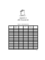
Appendix A
ASCII Character Set
Table A-1. ASCII Character Set
ASCII
Value
Full ASCII
Code 39
Encode Char.
Keystroke
ASCII
Value
Full ASCII
Code 39
Encode Char
Keystroke
000
%U
CTRL 2
024
$X
CTRL X
001
$A
CTRL A
025
$Y
CTRL Y
002
$B
CTRL B
026
$Z
CTRL Z
003
$C
CTRL C
027
%A
CTRL [
004
$D
CTRL D
028
%B
CTRL \
005
$E
CTRL E
029
%C
CTRL ]
006
$F
CTRL F
030
%D
CTRL 6
007
$G
CTRL G
031
%E
CTRL -
008
$H
CTRL H
032
Space
Space
009
$I
CTRL I
033
/A
!
010
$J
CTRL J
034
/B
‘
011
$K
CTRL K
035
/C
#
012
$L
CTRL L
036
/D
$
013
$M
CTRL M
037
/E
%
014
$N
CTRL N
038
/F
&
015
$O
CTRL O
039
/G
‘
016
$P
CTRL P
040
/H
(
A-1
LS 1004 Product Reference Guide
Table A-1. (Continued) ASCII Character Set
017
$Q
CTRL Q
041
/I
)
018
$R
CTRL R
042
/J
*
019
$S
CTRL S
043
/K
+
020
$T
CTRL T
044
/L
,
021
$U
CTRL U
045
-
-
022
$V
CTRL V
046
.
.
023
$W
CTRL W
047
/
/
ASCII
Value
Full ASCII
Code 39
Encode Char.
Keystroke
ASCII
Value
Full ASCII
Code 39
Encode Char
Keystroke
048
0
0
073
I
I
049
1
1
074
J
J
050
2
2
075
K
K
051
3
3
076
L
L
052
4
4
077
M
M
053
5
5
078
N
N
054
6
6
079
O
O
055
7
7
080
P
P
056
8
8
081
Q
Q
057
9
9
082
R
R
058
/Z
:
083
S
S
059
%F
;
084
T
T
060
%G
<
085
U
U
061
%H
=
086
V
V
062
%I
>
087
W
W
063
%J
?
088
X
X
064
%V
@
089
Y
Y
065
A
A
090
Z
Z
066
B
B
091
%K
[
067
C
C
092
%L
\
A-2
ASCII Character Set
Table A-1. (Continued) ASCII Character Set
068
D
D
093
%M
]
069
E
E
094
%N
^
070
F
F
095
%O
_
071
G
G
096
%W
‘
072
H
H
097
+A
a
ASCII
Value
Full ASCII
Code 39
Encode Char.
Keystroke
ASCII
Value
Full ASCII
Code 39
Encode Char
Keystroke
098
+B
b
113
+Q
q
099
+C
c
114
+R
r
100
+D
d
115
+S
s
101
+E
e
116
+T
t
102
+F
f
117
+U
u
103
+G
g
118
+V
v
104
+H
h
119
+W
w
105
+I
i
120
+X
x
106
+J
j
121
+Y
y
107
+K
k
122
+Z
z
108
+L
l
123
%P
{
109
+M
m
124
%Q
|
110
+N
n
125
%R
}
111
+O
o
126
%S
~
112
+P
p
127
Undefined
Table A-2. ASCII Character Set
264
ALT 2
275
ALT K
286
ALT V
265
ALT A
276
ALT L
287
ALT W
266
ALT B
277
ALT M
288
ALT X
267
ALT C
278
ALT N
289
ALT Y
A-3
LS 1004 Product Reference Guide
268
ALT D
279
ALT O
290
ALT Z
269
ALT E
280
ALT P
291
ALT [
270
ALT F
281
ALT Q
292
ALT \
271
ALT G
282
ALT R
293
ALT ]
272
ALT H
283
ALT S
294
ALT 6
273
ALT I
284
ALT T
295
ALT -
274
ALT J
285
ALT U
Misc. Key
Keystroke
Misc. Key
Keystroke
Misc. Key
Keystroke
301
PA 1
309
CMD 7
317
°
302
PA 2
310
CMD 8
318
1/2
303
CMD 1
311
CMD 9
319
¶
304
CMD 2
312
CMD 10
320
§
305
CMD 3
313
¥
321
|
306
CMD 4
314
£
322
0/00
307
CMD 5
315
¤
308
CMD 6
316
¬
A-4
ASCII Character Set
PF Keys
Keystroke
PF Keys
Keystroke
PF Keys
Keystroke
401
PF 1
409
PF 9
417
PF 17
402
PF 2
410
PF 10
418
PF 18
403
PF 3
411
PF 11
419
PF 19
404
PF 4
412
PF 12
420
PF 20
405
PF 5
413
PF 13
421
PF 21
406
PF 6
414
PF 14
422
PF 22
407
PF 7
415
PF 15
423
PF 23
408
PF 8
416
PF 16
424
PF 24
F Keys
Keystroke
F Keys
Keystroke
F Keys
Keystroke
501
F1
514
F 14
527
F 27
502
F2
515
F 15
528
F 28
503
F3
516
F 16
529
F 29
504
F4
517
F 17
530
F 30
505
F5
518
F 18
531
F 31
506
F6
519
F 19
532
F 32
507
F7
520
F 20
533
F 33
508
F8
521
F 21
534
F 34
509
F9
522
F 22
535
F 35
510
F 10
523
F 23
536
F 36
511
F 11
524
F 24
537
F 37
512
F 12
525
F 25
538
F 38
513
F 13
526
F 26
539
F 39
A-5
LS 1004 Product Reference Guide
Numeric
Keypad
Keystroke
Numeric
Keypad
Keystroke
Numeric
Keypad
Keystroke
642
*
649
1
656
8
643
+
650
2
657
9
644
Undefined
651
3
658
Enter
645
-
662
4
659
Num Lock
646
.
663
5
660
00
647
/
664
6
648
0
665
7
Extended
Keypad
Keystroke
Extended
Keypad
Keystroke
Extended
Keypad
Keystroke
701
Break
708
Backspace
715
Up Arrow
702
Delete
709
Tab
716
Dn Arrow
703
Pg Up
710
Print Screen
717
Left Arrow
704
End
711
Insert
718
Right Arrow
705
Pg Dn
712
Home
719
Back Tab
706
Pause
713
Enter
707
Scroll Lock
714
Escape
Note:
A-6
Table A-1 applies to the LS 1004-I000. Tables A-1 and A-2 apply to the LS
1004-I100 only.
Glossary
ASCII - American Standard Code for Information Interchange. A 7 bit code
representing 128 letters, numerals, punctuation marks, and control
characters. It is a standard data transmission code in the U.S.
BIT - Binary digit. One bit is the basic unit of binary information. Generally,
eight consecutive bits compose one byte of data. The pattern of 0 and 1 values
within the byte determines its meaning.
BOOKLAND EAN - A specially-formatted European Article Numbering
symbol with 13 characters (EAN-13), the first 3 of which are “978”.
BYTE - On an addressable boundary, eight adjacent binary digits (0 and 1)
combined in a pattern to represent a specific character or numeric value. Bits
are numbered from the right, 0 through 7, with bit 0 the low-order bit. One byte
in memory can be used to store one ASCII character.
CDRH - Center for Devices and Radiological Health. A federal agency
responsible for regulating laser product safety. This agency specifies various
laser operation classes based on power output during operation.
CHECK DIGIT - A digit used to verify a correct symbol decode. The scanner
inserts the decoded data into an arithmetic formula and checks that the
resulting number matches the encoded check digit. Check digits are required
for UPC but are optional for other symbologies. Using check digits decreases
the chance of substitution errors when a symbol is decoded.
CODABAR - A discrete self-checking code with a character set consisting of
digits 0 to 9 and six additional characters: (- $ : / , +).
Glossary-1
LS 1004 Product Reference Guide
CODE 128 - A high density symbology which allows the controller to encode
all 128 ASCII characters without adding extra symbol elements.
CODE 3 OF 9 (CODE 39) - A versatile and widely used alphanumeric bar code
symbology with a set of 43 character types, including all uppercase letters,
numerals from 0 to 9, and 7 special characters (- . / + % $ and space). The code
name is derived from the fact that 3 of 9 elements representing a character are
wide, while the remaining 6 are narrow.
CODE 93 - An industrial symbology compatible with Code 39 but offering a
full character ASCII set and a higher coding density than Code 39.
CONTINUOUS SYMBOLOGY - A bar code or symbol in which all spaces
within the symbol are parts of characters. There are no intercharacter gaps in a
continuous code. The absence of gaps allows for greater information density.
DECODE - To recognize a bar code symbology (e.g., UPC/EAN) and then
analyze the content of the specific bar code scanned.
DECODE ALGORITHM - A decoding scheme that converts pulse widths into
data representation of the letters or numbers encoded within a bar code
symbol.
DISCRETE SYMBOLOGY - A bar code or symbol in which the spaces
between characters (intercharacter gaps) are not part of the code.
DISCRETE 2 OF 5 - A binary bar code symbology representing each character
by a group of five bars, two of which are wide. The location of wide bars in the
group determines which character is encoded; spaces are insignificant. Only
numeric characters (0 to 9) and START/STOP characters may be encoded.
EAN - European Article Number. This European/International version of the
UPC provides its own coding format and symbology standards. Element
dimensions are specified metrically. EAN is used primarily in retail.
HOST COMPUTER - A computer that serves other terminals in a network,
providing such services as computation, database access, supervisory
programs, and network control.
Glossary-2
Glossary
IEC - International Electrotechnical Commission. This international agency
regulates laser safety by specifying various laser operation classes based on
power output during operation.
IEC CLASS I (IEC 825 Class I) - This is the lowest power IEC laser
classification. Conformity is ensured through a software restriction of 25
seconds of laser operation within any 100 second window and an automatic
laser shutdown if the scanner's oscillating mirror fails.
INTERCHARACTER GAP - The space between two adjacent bar code
characters in a discrete bar code.
INTERLEAVED BAR CODE - A bar code in which characters are paired
together, using bars to represents the first character and the intervening spaces
to represent the second.
INTERLEAVED 2 OF 5 - A binary bar code symbology representing character
pairs in groups of five bars and five interleaved spaces. Interleaving provides
for greater information density. The location of wide elements (bar/spaces)
within each group determines which characters are encoded. This
continuous code type uses no intercharacter spaces. Only numeric (0 to 9)
and START/STOP characters may be encoded.
LASER - An acronym for Light Amplification by Stimulated Emission of
Radiation. The laser is an intense light source. Light from a laser is all the same
frequency, unlike the output of an incandescent bulb. Laser light is typically
coherent and has a high energy density.
LASER DIODE - A semiconductor type of laser connected to a power source
to generate a laser beam. This laser type is a compact source of coherent light.
PARAMETER - A variable that can have different values assigned to it.
PROGRAMMING MODE - The state in which a scanner is configured for
parameter values. See SCANNING MODE.
QUIET ZONE - A clear space, containing no dark marks, which precedes the
start character of a bar code symbol and follows the stop character.
Glossary-3
LS 1004 Product Reference Guide
REDUNDANCY - A decoding method which requires a bar code be
recognized redundantly on a number of sweeps of the scan beam before a
decode is declared. While slowing the time-to-decode, redundancy can help
lower the possibility of a mis-decode of poorly printed symbols.
SCANNER - An electronic device used to scan bar code symbols and produce
a digitized pattern that corresponds to the bars and spaces of the symbol. Its
three main components are:
1. Light source (laser or photoelectric cell) - illuminates a bar code.
2. Photodetector - registers the difference in reflected light (more light
reflected from spaces).
3. Signal conditioning circuit - transforms optical detector output into a
digitized bar pattern.
SCANNING MODE - The scanner is energized, programmed, and ready to
read a bar code.
SCANNING SEQUENCE - A method of programming or configuring
parameters for a bar code reading system by scanning bar code menus.
SELF-CHECKING CODE - A symbology that uses a checking algorithm to
detect encoding errors within the characters of a bar code symbol.
START/STOP CHARACTER - A pattern of bars and spaces that provides the
scanner with start and stop reading instructions and scanning direction. The
start and stop characters are normally to the left and right margins of a
horizontal code.
SYMBOL - A scannable unit that encodes data within the conventions of a
certain symbology, usually including start/stop characters, quiet zones, data
characters, and check characters.
SYMBOLOGY - The structural rules and conventions for representing data
within a particular bar code type (e.g. UPC/EAN, Code 39).
Glossary-4
Glossary
UPC - Universal Product Code. A relatively complex numeric symbology. Each
character consists of two bars and two spaces, each of which can be any of
four widths. The standard symbology for retail food packages in the United
States.
Glossary-5
LS 1004 Product Reference Guide
Glossary-6
Index
A
Accessories . . . . . . . . . . . . . . . . . . . . . . . . . . 3-4
Optional . . . . . . . . . . . . . . . . . . . . . . . . 3-4
Required . . . . . . . . . . . . . . . . . . . . . . . 3-4
Aggressive Scan Disable . . . . . . . . . . . . . . . 4-14
Aggressive Scan Enable . . . . . . . . . . . . . . . 4-14
Aggressive Scan Mode . . . . . . . . . . . . . . . . 4-14
Aiming . . . . . . . . . . . . . . . . . . . . . . . . . . . . . 2-4
Ambient Light Immunity . . . . . . . . . . . . . . . 3-7
ASCII Character Set . . . . . . . . . . . . . . . . . . . A-1
B
Battery Box Operation . . . . . . . . . . . . . . . . . 3-3
Changing the Battery . . . . . . . . . . . . . . 3-3
Recharging a Ni-Cd Battery . . . . . . . . . 3-3
Battery Operation . . . . . . . . . . . . . . . . . . . . 1-7
Baud Rate . . . . . . . . . . . . . . . . . . . . . . . . . 4-34
Beeper after Decode . . . . . . . . . . . . . . . . . . 4-11
Beeper Disable . . . . . . . . . . . . . . . . . . . . . . 4-11
Beeper Enable . . . . . . . . . . . . . . . . . . . . . . 4-11
Beeper Indications . . . . . . . . . . . . . . . . . . . . 3-9
Beeper Operation . . . . . . . . . . . . . . . . . . . . . 3-7
Beeper Tone . . . . . . . . . . . . . . . . . . . . . . . . 4-12
Beeper Tone High . . . . . . . . . . . . . . . . . . . 4-12
Beeper Tone Low . . . . . . . . . . . . . . . . . . . . 4-12
Beeper Tone Mid . . . . . . . . . . . . . . . . . . . . 4-12
Beeper Volume . . . . . . . . . . . . . . . . . . . . . 4-12
Beeper Volume High . . . . . . . . . . . . . . . . . 4-12
Beeper Volume Low . . . . . . . . . . . . . . . . . 4-12
Beeper Volume Mid . . . . . . . . . . . . . . . . . . 4-12
C
Changing Battery . . . . . . . . . . . . . . . . . . . . . 3-3
Check Parity . . . . . . . . . . . . . . . . . . . . . . . 4-36
CLSI Editing . . . . . . . . . . . . . . . . . . . . . . . 4-29
Codabar . . . . . . . . . . . . . . . . . . . . . . . . . . 4-29
Code 128 . . . . . . . . . . . . . . . . . . . . . . . . . 4-22
Code 39 . . . . . . . . . . . . . . . . . . . . . . . . . . 4-23
CODE 39 Modulo 43 Check . . . . . . . . . . 4-23
Code 93 . . . . . . . . . . . . . . . . . . . . . . . . . . 4-24
code ID characters . . . . . . . . . . . . . . . . . . . 4-7
Code Types . . . . . . . . . . . . . . . . . . . . . . . . 4-15
Connecting to Host . . . . . . . . . . . . . . . . . . 1-5
RS-232C . . . . . . . . . . . . . . . . . . . . . . . 1-5
Convert UPC-E to UPC-A . . . . . . . . . . . . . 4-18
D
D 2 of 5 Modulo 10 Check . . . . . . . . . . . . 4-27
Data Acquisition Time . . . . . . . . . . . . . . . . 3-8
Data Format . . . . . . . . . . . . . . . . . . . . . . . 4-36
Data Options . . . . . . . . . . . . . . . . . . . . . . 4-30
Decode Attempt Time . . . . . . . . . . . . . . . . 4-13
Decode Capability . . . . . . . . . . . . . . . . . . . 3-7
Decode Depth of Field . . . . . . . . . . . . . . . . 3-7
Decode Redundancy . . . . . . . . . . . . . . . . . 4-15
Decode UPC Only (Not EAN) . . . . . . . . . 4-17
Decode UPC/EAN Supplemental . . . . . . . 4-19
Decode Zone . . . . . . . . . . . . . . . . . . . . . . . 3-6
Default Table . . . . . . . . . . . . . . . . . . . . . . . 4-3
default table
RS-232 host type . . . . . . . . . . . . . . . . . 4-6
Dimensions . . . . . . . . . . . . . . . . . . . . . . . . . 3-8
Disable All Code Types 4-16
Disable ALL CODE TYPES
Decode Redundancy . . . . . . . . . . 4-15
Disable CODABAR Decode Redundancy . 4-15
Discrete 2 of 5 . . . . . . . . . . . . . . . . . . . . . 4-27
Index-1
LS 1004 Product Reference Guide
Do Not Transmit “NO DECODE”
Message . . . . . . . . . . . . . . . . . . 4-15
Durability . . . . . . . . . . . . . . . . . . . . . . . . . . 3-8
E
EAN Zero Extend . . . . . . . . . . . . . . . . . . . 4-18
Enable All Code Types . . . . . . . . . . . . . . . 4-16
Enable ALL CODE TYPES Decode
Redundancy . . . . . . . . . . . . . . . . 4-15
Enable CODABAR Decode Redundancy . 4-15
Enable/Disable Codabar . . . . . . . . . . . . . . 4-29
Enable/Disable Code 128 . . . . . . . . . . . . . 4-22
Enable/Disable Code 39 . . . . . . . . . . . . . . 4-23
Enable/Disable Code 39 Full ASCII . . . . . 4-24
Enable/Disable Code 93 . . . . . . . . . . . . . . 4-24
Enable/Disable Code I 2 of 5 . . . . . . . . . . 4-24
Enable/Disable D 2 of 5 . . . . . . . . . . . . . . 4-27
Enable/Disable UPC/EAN . . . . . . . . . . . . . 4-17
Errors While Scanning . . . . . . . . . . . . . . . . 4-8
F
Fixed Lengths for Code 2 of 5 . . . . . . . . . 4-27
Fixed Lengths for Code I 2 of 5 . . . . . . . . 4-24
Flying Lead Connector . . . . . . . . . . . . . . . . 1-6
H
Hardware Handshaking . . . . . . . . . . . . . . 4-37
Host Interface Select . . . . . . . . . . . . . . . . . . 4-9
hosts
RS-232 defaults . . . . . . . . . . . . . . . . . . 4-6
RS-232 host type . . . . . . . . . . . . . . . . 4-10
Humidity . . . . . . . . . . . . . . . . . . . . . . . . . . 3-8
I
I 2 of 5 Modulo 10 Check . . . . . . . . . . . . 4-26
IBM 468X/9X . . . . . . . . . . . . . . . . . . . . . . . 1-8
Installing the Cable . . . . . . . . . . . . . . . . . . . 1-4
Intercharacter Delay . . . . . . . . . . . . . . . . . 4-40
Interleaved 2 of 5 . . . . . . . . . . . . . . . . . . . 4-24
ITF14/EAN13 Conversion . . . . . . . . . . . . 4-26
Index-2
K
Keyboard Wedges . . . . . . . . . . . . . . . . . . . . 1-8
L
Laser Classifications . . . . . . . . . . . . . . . . . . 3-8
LS 1004
Ambient Light Immunity . . . . . . . . . . . 3-7
Beeper Indications . . . . . . . . . . . . . . . . 3-9
Beeper Operation . . . . . . . . . . . . . . . . . 3-7
Data Acquisition Time . . . . . . . . . . . . . 3-8
Decode Capability . . . . . . . . . . . . . . . . 3-7
Decode Depth of Field . . . . . . . . . . . . . 3-7
Dimensions . . . . . . . . . . . . . . . . . . . . . . 3-8
Durability . . . . . . . . . . . . . . . . . . . . . . . 3-8
Humidity . . . . . . . . . . . . . . . . . . . . . . . 3-8
Laser Classifications . . . . . . . . . . . . . . . 3-8
Maximum Element Width . . . . . . . . . . 3-8
Minimum Element Width . . . . . . . . . . . 3-8
Operating Temperature . . . . . . . . . . . . 3-8
Pinouts . . . . . . . . . . . . . . . . . . . . . . . . .3-8
Pitch . . . . . . . . . . . . . . . . . . . . . . . . . . . 3-7
Power Requirements . . . . . . . . . . . . . . . 3-7
Print Contrast Minimum . . . . . . . . . . . 3-7
Scan Repetition Rate . . . . . . . . . . . . . . 3-7
Skew Tolerance . . . . . . . . . . . . . . . . . . 3-7
Start-Up Time . . . . . . . . . . . . . . . . . . . . 3-8
Storage Temperature . . . . . . . . . . . . . . 3-8
LS 100x
Accessories . . . . . . . . . . . . . . . . . . . . . . 3-4
Battery Box Operation . . . . . . . . . . . . . 3-3
Changing Battery . . . . . . . . . . . . . . . . . 3-3
Decode Zone . . . . . . . . . . . . . . . . . . . . 3-6
Default Table . . . . . . . . . . . . . . . . . . . . 4-3
Installing the Cable . . . . . . . . . . . . . . . . 1-4
Maintaining . . . . . . . . . . . . . . . . . . . . . 3-3
Maintenance . . . . . . . . . . . . . . . . . . . . . 3-4
Optional Accessories . . . . . . . . . . . . . . 3-4
Required Accessories . . . . . . . . . . . . . . 3-4
Setup . . . . . . . . . . . . . . . . . . . . . . . . . . 1-3
Switching Cables . . . . . . . . . . . . . . . . . 1-5
Technical Specifications . . . . . . . . . . . . 3-6
Unpacking . . . . . . . . . . . . . . . . . . . . . . 1-3
LS 100x Decode Zone . . . . . . . . . . . . . 2-3, 3-6
Index
M
Maintenance . . . . . . . . . . . . . . . . . . . . . . . . 3-4
Maximum Element Width . . . . . . . . . . . . . . 3-8
Minimum Element Width . . . . . . . . . . . . . . 3-8
N
NOTIS Editing . . . . . . . . . . . . . . . . . . . . . 4-29
O
OCIA . . . . . . . . . . . . . . . . . . . . . . . . . . . . . . 1-8
OCR . . . . . . . . . . . . . . . . . . . . . . . . . . . . . . 1-8
Operating Mode . . . . . . . . . . . . . . . . . . . . 4-14
Operating Mode Continous . . . . . . . . . . . . 4-14
Operating Mode Low Power . . . . . . . . . . . 4-14
Operating Temperature . . . . . . . . . . . . . . . . 3-8
Optional Accessories . . . . . . . . . . . . . . . . . . 3-4
P
Parameter Descriptions . . . . . . . . . . . . . . . . 4-9
Aggressive Scan Mode . . . . . . . . . . . . 4-14
Baud Rate . . . . . . . . . . . . . . . . . . . . . 4-34
Beeper After Decode . . . . . . . . . . . . . . 4-11
Beeper Tone . . . . . . . . . . . . . . . . . . . . 4-12
Beeper Volume . . . . . . . . . . . . . . . . . . 4-12
Check Parity . . . . . . . . . . . . . . . . . . . . 4-36
CLSI Editing . . . . . . . . . . . . . . . . . . . . 4-29
Codabar . . . . . . . . . . . . . . . . . . . . . . . 4-29
Code 128 . . . . . . . . . . . . . . . . . . . . . . 4-22
Code 39 . . . . . . . . . . . . . . . . . . . . . . . 4-23
Code 39 Modulo 43 Check . . . . . . . . 4-23
Code 93 . . . . . . . . . . . . . . . . . . . . . . . 4-24
Code Types . . . . . . . . . . . . . . . . . . . . 4-15
Convert UPC-E to UPC-A . . . . . . . . . 4-18
D 2 of 5 Modulo 10 Check . . . . . . . . 4-27
Data Format . . . . . . . . . . . . . . . . . . . . 4-36
Data Options . . . . . . . . . . . . . . . . . . . 4-30
Decode Attempt Time . . . . . . . . . . . . 4-13
Decode Redundancy . . . . . . . . . . . . . . 4-15
Decode UPC Only (Not EAN) . . . . . . 4-17
Decode UPC/EAN Supplemental . . . . 4-19
Discrete 2 of 5 . . . . . . . . . . . . . . . . . . 4-27
EAN Zero Extend . . . . . . . . . . . . . . . 4-18
Enable/Disable Codabar . . . . . . . . . . . 4-29
Enable/Disable Code 128 . . . . . . . . . 4-22
Enable/Disable Code 39 . . . . . . . . . . 4-23
Enable/Disable Code 39 Full ASCII . . 4-24
Enable/Disable Code 93 . . . . . . . . . . 4-24
Enable/Disable Code I 2 of 5 . . . . . . . 4-24
Enable/Disable D 2 of 5 . . . . . . . . . . . 4-27
Fixed Lengths for Code 2 of 5 . . . . . . 4-27
Fixed Lengths for Code I 2 of 5 . . . . . 4-24
Hardware Handshaking . . . . . . . . . . 4-37
Host Interface Select . . . . . . . . . . . . . . 4-9
I 2 of 5 Modulo 10 Check . . . . . . . . . 4-26
Intercharacter Delay . . . . . . . . . . . . . 4-40
Interleaved 2 of 5 . . . . . . . . . . . . . . . 4-24
ITF14/EAN13 Conversion . . . . . . . . . 4-26
NOTIS Editing . . . . . . . . . . . . . . . . . 4-29
Operating Mode . . . . . . . . . . . . . . . . 4-14
Parity . . . . . . . . . . . . . . . . . . . . . . . . . 4-35
Power On Beep Enable/Disable . . . . . 4-11
Prefix . . . . . . . . . . . . . . . . . . . . . . . . . 4-31
Prefix/Suffix Values . . . . . . . . . . . . . . 4-33
RS-232C . . . . . . . . . . . . . . . . . . . . . . 4-34
Send Code 128 Function Character . . 4-22
Set Parameter Defaults . . . . . . . . . . . . 4-9
Software Handshaking . . . . . . . . . . . 4-37
Stop Bit Select . . . . . . . . . . . . . . . . . . 4-36
Suffix 4-31 . . . . . . . . . . . . . . . . . . . . . . . . .
Transmit "No Decode" Message . . . . 4-15
Transmit Code 39 Check Digit . . . . . 4-23
Transmit Code ID Character . . . . . . . 4-30
Transmit UPC-E/UPC-A . . . . . . . . . . 4-17
UPC A and E Preambles . . . . . . . . . . 4-20
UPC/EAN . . . . . . . . . . . . . . . . . . . . . 4-17
UPC/EAN Security Level . . . . . . . . . . 4-21
parameter menus
RS-232 host type . . . . . . . . . . . . . . . . 4-10
Parity . . . . . . . . . . . . . . . . . . . . . . . . . . . . 4-35
Pinouts - LS 1004 . . . . . . . . . . . . . . . . . . . . 3-8
Pitch . . . . . . . . . . . . . . . . . . . . . . . . . . . . . . 3-7
Power On Beep Disable . . . . . . . . . . . . . . 4-11
Power On Beep Enable . . . . . . . . . . . . . . . 4-11
Power On Beep Enable/Disable . . . . . . . . . 4-11
Power Requirements . . . . . . . . . . . . . . . . . . 3-7
Prefix . . . . . . . . . . . . . . . . . . . . . . . . . . . . 4-31
Index-3
LS 1004 Product Reference Guide
Prefix None . . . . . . . . . . . . . . . . . . . . 4-31
Prefix STX . . . . . . . . . . . . . . . . . . . . . 4-31
User’s Choice Prefix Character . . . . . 4-31
Prefix/Suffix Values . . . . . . . . . . . . . . . . . 4-33
Print Contrast Minimum . . . . . . . . . . . . . . 3-7
R
Ready, Test, Scan . . . . . . . . . . . . . . . . . . . . 2-3
Recharging a Ni-Cd Battery . . . . . . . . . . . . 3-3
RS-232
code ID characters . . . . . . . . . . . . . . . . 4-7
host type . . . . . . . . . . . . . . . . . . . . . . 4-10
host type defaults . . . . . . . . . . . . . . . . . 4-6
RS-232C . . . . . . . . . . . . . . . . . . . . . . . 1-5, 4-34
Battery Operation . . . . . . . . . . . . . . . . 1-7
External Power Connection
Flying Lead Connector . . . . . . . . . 1-6
External Power Connection - 25-pin
connector . . . . . . . . . . . . . . . . . . . 1-7
External Power Connection - Synapse . 1-5
S
Scan Repetition Rate . . . . . . . . . . . . . . . . . . 3-7
Scanning Sequence Example . . . . . . . . . . . . 4-7
Send CODE 128 Function Character . . . . 4-22
SET ALL DEFAULTS . . . . . . . . . . . . . . . . . 4-9
Set Parameter Defaults . . . . . . . . . . . . . . . . 4-9
SET RS-232C HOST . . . . . . . . . . . . . . . . . 4-9
Set Synapse Host . . . . . . . . . . . . . . . . . . . . . 4-9
Set-Up . . . . . . . . . . . . . . . . . . . . . . . . . . . . . 1-3
Installing the Cable . . . . . . . . . . . . . . . 1-4
Switching Cables . . . . . . . . . . . . . . . . . 1-5
Setup
Unpacking . . . . . . . . . . . . . . . . . . . . . . 1-3
Skew Tolerance . . . . . . . . . . . . . . . . . . . . . . 3-7
Software Handshaking . . . . . . . . . . . . . . . 4-37
Index-4
specular reflection . . . . . . . . . . . . . . . . . . . . 2-4
Start-Up Time . . . . . . . . . . . . . . . . . . . . . . . 3-8
Stop Bit Select . . . . . . . . . . . . . . . . . . . . . . 4-36
Storage Temperature . . . . . . . . . . . . . . . . . . 3-8
Suffix . . . . . . . . . . . . . . . . . . . . . . . . . . . . . 4-31
Suffix CR . . . . . . . . . . . . . . . . . . . . . . 4-32
Suffix CR/LF . . . . . . . . . . . . . . . . . . . 4-32
Suffix ETX . . . . . . . . . . . . . . . . . . . . . 4-32
Suffix HT . . . . . . . . . . . . . . . . . . . . . . 4-32
Suffix LF . . . . . . . . . . . . . . . . . . . . . . . 4-32
Suffix None . . . . . . . . . . . . . . . . . . . . 4-32
Switching the Cable . . . . . . . . . . . . . . . . . . . 1-5
Synapse . . . . . . . . . . . . . . . . . . . . . . . . 1-5, 1-8
T
Technical Specifications . . . . . . . . . . . . . . . . 3-6
Transmit “NO DECODE” Message . . . . . 4-15
Transmit “No Decode” Message . . . . . . . . 4-15
Transmit CODE 39 Check Digit . . . . . . . . 4-23
Transmit Code ID Character . . . . . . . . . . . 4-30
Transmit UPC-E/UPC-A . . . . . . . . . . . . . . 4-17
Troubleshooting’ . . . . . . . . . . . . . . . . . . . . . 3-5
U
UPC A and E Preamble(s . . . . . . . . . . . . . . 4-20
UPC/EAN . . . . . . . . . . . . . . . . . . . . . . . . . 4-17
UPC/EAN Security Level . . . . . . . . . . . . . . 4-21
W
Wand Emulation . . . . . . . . . . . . . . . . . . . . . 1-8
Wand Emulation, OCIA, OCR, and Keyboard
Wedges . . . . . . . . . . . . . . . . . . . . . 1-8
What If . . . . . . . . . . . . . . . . . . . . . . . . . . . .3-5
Tell Us What You Think...
We’d like to know what you think about this Manual. Please take a moment to fill
out this questionaire and fax this form to: (631) 738-3318, or mail to:
Symbol Technologies, Inc.
One Symbol Plaza M/S B-4
Holtsville, NY 11742-1300
Attn: Technical Publications Manager
IMPORTANT: If you need product support, please call the appropriate customer
support number provided. Unfortunately, we cannot provide customer support at
the fax number above.
User’s Manual Title:
(please include revision level)
How familiar were you with this product before using this manual?
Very familiar
Slightly familiar
Not at all familiar
Did this manual meet your needs? If not, please explain.
What topics need to be added to the index?, if applicable
What topics do you feel need to be better discussed? Please be specific.
What can we do to further improve our manuals?
Thank you for your input—We value your comments.
LS 1000 Series Product Reference Guide