1
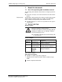
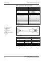
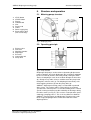
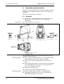
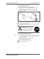
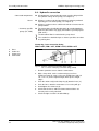
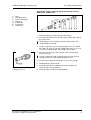
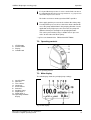
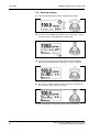
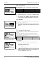
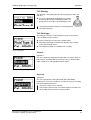
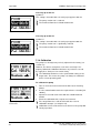
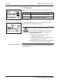
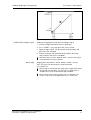
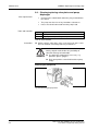
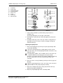
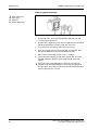
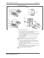
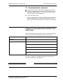
Diaphragm metering pump
SIMDOS
®
FEM 1.10 KT .18 S
S / RC
.18
KT / TT / FT [Chapt. 4]
1.10
FEM / UFEM
- / PMLxxxx / PLxxxx [Chapt. 1]
Operating Manual
It is important to read and
comply with all instructions in
this operating and installation
manual.
An additional letter before
the FEM model code is a
country-specific designation,
with no technical relevance.
KNF FLODOS AG
Wassermatte 2
6210 Sursee, Switzerland
Tel. +41 (0)41 925 00 25
Fax +41 (0)41 925 00 35
www.knf-flodos.ch
[email protected]
KNF Flodos BA_SIMDOS_EN_02_160044.docx
Translation of original operating manual
Please keep for future reference!
Items included on delivery:
KNF FLODOS AG
Wassermatte 2
6210 Sursee, Switzerland
Tel. +41 (0)41 925 00 25
Fax +41 (0)41 925 00 35
www.knf-flodos.ch
[email protected]
SIMDOS metering pump
Mains plug
RC cable (for RC version only)
Operating manual
Brief user guide
Operating manual CD-ROM
Connection kit: hose and screw connectors
Safety provisions
The SIMDOS 10 metering pump complies with the safety
provisions of the EC low-voltage directive 2006/95/EC and the EC
directive on electromagnetic compatibility 2004/108/EG. The
following standards are applicable:
Contents
1.
1.1.
1.2.
2.
2.1.
2.2.
3.
4.
4.1.
4.2.
4.3.
4.4.
4.5.
4.6.
4.7.
5.
5.1.
5.2.
5.3.
5.4.
6.
6.1.
6.2.
6.3.
6.4.
6.5.
6.6.
7.
7.1.
7.2.
7.3.
7.4.
EN 61010-1
EN 61326-1
Page
About this document
3
Use of the operating and installation manual3
Symbols and flags
3
Use
4
Intended use
4
Improper use
4
Safety
5
Technical data
7
Pump materials
7
Hydraulic ratings
7
Accuracy / reproducibility
8
Hydraulic connections
8
Electrical data
9
Other parameters
9
External drive (RC version only)
10
Structure and operation
11
Metering pump structure
11
Operating principle
11
Metering pump functions
12
Functions overview
13
Assembly and connection
14
Assembly
14
Electrical connection
15
External drive (RC version)
15
Hydraulic connection
16
Shutdown
18
Transport and interim storage
18
Operation
18
Initial start-up
18
Operating controls
19
Main display
19
Switching the pump on and off
20
Contents
7.5.
7.6.
7.7.
7.8.
7.9.
7.10.
7.11.
7.12.
7.13.
7.14.
7.15.
7.16.
7.17.
7.18.
7.19.
7.20.
8.
8.1.
8.2.
8.3.
8.4.
9.
9.1.
9.2.
9.3.
Page
Starting the pump
21
Interrupting a pumping operation
21
Stopping the pumping operation
21
Entering settings
22
Specified flow
24
Flow unit
24
Timeout with time counter
24
Priming
25
Fluid type
25
Calibration
26
System settings
27
Back to main menu
27
Language setting
27
Auto start
28
Contrast
29
Reset
29
RC version – external drive
30
External drive analogue input
30
Digital input 1, Start/Stop
32
Digital input 2, Reset/Prime/Pedal switch 34
Digital output
36
Maintenance
37
Maintenance plan
37
Cleaning
37
Cleaning/replacing valve plates and pump
diaphragm
38
10. Troubleshooting
42
11. Spare parts and accessories
44
11.1. Spare parts
44
11.2. Accessories
44
12. Decontamination statement
45
SIMDOS diaphragm metering pump
About this document
1.
About this document
1.1. Use of the operating and installation manual
The operating and installation manual forms an integral part of the
pump.
Please be sure to pass the manual on to the next owner of the
device.
Project pumps
Specifications and instructions for customer-specific project pumps
(model numbers beginning with “PL” or “PML”) may differ from
those set down in the operating and installation manual.
For project pumps, it is also necessary to observe the agreed
specifications.
1.2. Symbols and flags
Warning symbol
Warning regarding a potential danger.
Possible consequences of failure to comply with the
warning. The word used, e.g. “warning”, indicates
WARNING the level of danger present.
Precautions required to prevent the danger and
its consequences.
Levels of danger
Word
Meaning
DANGER
Warning of an
imminent danger
WARNING Warning of a
potential danger
CAUTION Warning of a
potentially
dangerous
situation
Consequences of noncompliance
Death or serious injury, or major
damage to property
Possible death or serious injury,
or major damage to property
Possibility of slight injury or
damage to property
Tab. 1: Levels of danger
Other flags and symbols
Identifies an action (step) to be carried out.
1. Identifies the first step of an action. Further numbered steps
follow.
Identifies important information.
KNF Flodos BA_SIMDOS_EN_02_160044.docx
Translation of original operating manual
3
Use
SIMDOS diaphragm metering pump
2.
Use
2.1. Intended use
The pump is a fluid pumping and metering device.
Operator’s responsibility
Operating parameters and
conditions
The pump must be installed and operated only in accordance with
the operating parameters and conditions described in Chapter 4,
Technical data.
Protect the pump from moisture.
The pump may be operated only when fully assembled.
Requirements for pumped
medium
Before use, check that the materials of the pump head, housing,
diaphragm and valves are compatible with the pumped medium.
Before starting to pump, check that the medium can be pumped
safely in this specific situation.
The temperature of the medium must be within the permitted
temperature range (see Chapter 4).
The pumping medium must not contain any solids, since these
could impair the pump’s operation. If the presence of solids cannot
be prevented, a filter of < 50 µm and with a sufficient filter area
must be installed upstream from the pump.
2.2. Improper use
The pump must not be operated in a potentially explosive
atmosphere.
The party commissioning the pump is responsible for ensuring
compliance with relevant standards if the pump is used in the
medicine or food sectors.
4
KNF Flodos BA_SIMDOS_EN_02_160044.docx
Translation of original operating manual
SIMDOS diaphragm metering pump
3.
Safety
Safety
Note the safety notes in Chapter 6, Assembly and connection,
and Chapter 7, Operation
The pump is constructed according to the generally accepted rules
of the technology, and occupational health and safety and
accident prevention provisions. Hazardous situations with the
possibility of injuries to the user or other persons, or damage to
the pump or other property, may, however, occur during use of the
device.
The pump must be operated only in technically sound condition
and for its intended purpose, with due regard for safety and
potential hazards and in accordance with this operating and
installation manual.
Personnel
Ensure all persons working with the pump have been appropriately
trained and familiarised with its use, or are qualified personnel.
This applies particularly to the assembly, connection and
maintenance of the equipment.
Ensure that relevant personnel have read and understood this
operating and installation manual, particularly the chapter on
safety.
Safety awareness
Accident prevention and safety rules must be observed at all times
while working on or using the pump.
Hazardous media
When pumping a hazardous medium, always observe the safety
rules for the medium in question.
Signs
Always comply with instruction signs placed on the pump, such as
flow direction arrows and the type plate, and keep these in a
clearly legible condition.
Environmental protection
All replacement parts must be stored and disposed of in
accordance with the precautions required under environmental
protection provisions. It is important to comply with both national
and international regulations. This applies particularly to parts that
have been contaminated with toxic materials.
Disposal
Dispose of all packaging in an environmentally appropriate
manner. The packaging materials are recyclable.
Ensure that the pump is disposed of in an environmentally
appropriate manner at the end of its useful life. Use
appropriate waste collection systems for the disposal of endof-life equipment. Used pumps contain valuable recyclable
materials.
KNF Flodos BA_SIMDOS_EN_02_160044.docx
Translation of original operating manual
5
Safety
SIMDOS diaphragm metering pump
EU directives/standards
The pumps are in accordance with the requirements of the
guidelines 2011/65/EU (ROHS2)
The pump complies with all relevant provisions of the following
directives: the EC machinery directive 2006/42/EC, safety
provisions of the EC low-voltage directive 2006/95/EC and the EC
directive on electromagnetic compatibility 2004/108/EC.
The following harmonised standards are met:
EN 61010-1
EN 61326-1
Customer service and repairs
All repairs to the pump must be carried out solely by the
accredited KNF customer service entity.
Use only KNF original parts for all maintenance work.
6
KNF Flodos BA_SIMDOS_EN_02_160044.docx
Translation of original operating manual
SIMDOS diaphragm metering pump
Technical data
4.
Technical data
4.1. Pump materials
For KT models:
1)
Sub-assembly
Pump head
Valve plate / seals
Diaphragm
Housing
Tab. 2: KT
Material
PP
FFKM
PTFE-coated
PP
1) according to DIN ISO 1629 and 1043.1
For TT models:
1)
Sub-assembly
Pump head
Valve plate / seals
Diaphragm
Housing
Tab. 3: TT
Material
PVDF
FFKM
PTFE-coated
PP
1) according to DIN ISO 1629 and 1043.1
For FT models:
1)
Sub-assembly
Pump head
Valve plate / seals
Diaphragm
Housing
Tab. 4: FT
Material
PTFE
FFKM
PTFE-coated
PP
1) according to DIN ISO 1629 and 1043.1
4.2. Hydraulic ratings
Parameter
1), 2)
Flow rate [ml/min]
Max. metering volume [ml]
Metering time [mm:ss] [hh:mm]
Flow rate scale range
3)
Accuracy
3)
Reproducibility
Permitted pressure
[bar above atmospheric]
Suction head [m water column]
4)
Permitted medium viscosity [cSt]
Value
1–100
1–1,000
1s – 99h59min
1:100
+/- 2%
+/- 1%
6
3
150
Tab. 5: Hydraulic ratings
1) Measured with water at 20°C
2) Flow rates may vary from the values shown according to fluid viscosity,
pump head material and the hoses / hose connectors used. Calibration
with the pumped medium is required.
3) For calibrated pump and constant environmental conditions (see
section 5.5)
4) Lower flow rate for fluid type setting “Visk500cSt” (see section 7.13).
KNF Flodos BA_SIMDOS_EN_02_160044.docx
Translation of original operating manual
7
Technical data
SIMDOS diaphragm metering pump
4.3. Accuracy / reproducibility
Accuracy
The accuracy of the metering pump is appropriately characterised
by the maximum absolute error A and the maximum relative error
B.
max. inaccuracy ≤ A + B
Error
Absolute error A
Relative error B
Value
≤ ± 1‰ nominal value
≤ ±1.9% setting value
Tab. 6: Error A and error B
Example:
®
SIMDOS 10, nominal value of 100 ml/min
For a setting of 20 ml/min, the accuracy should therefore be within
the following error limits:
Inaccuracy
≤ (±1‰ x 100ml/min) + (±1.9% x 20ml/min)
≤ (±0.1ml/min) + (±0.38ml/min)
≤ ±0.48ml/min
≈ ±2% of setting value
Reproducibility
In constant environmental conditions and with the same hose
connection configuration, the pump achieves a reproducibility of
better than ±1%.
Greater inaccuracies may occur for fluids with a viscosity of
> 150 cSt or with a tendency to gassing out. Appropriate
adjustments may be made during calibration.
Factory calibration
Calibration
The metering pump has been calibrated to its nominal flow rate in
the factory. The specified flow rate is for water at 20°C with free
discharge flow.
The flow rate may differ from the calibrated value for some
applications, according to the medium, its viscosity, density and
temperature, pressure and installation type (e.g. cross-section
constrictions). For accurate metering, it is therefore desirable to
calibrate the metering pump (see section 7.14).
4.4. Hydraulic connections
Pump model
FEM 1.10 KT, TT
Connection type
Hose fitting,
i.d. 4mm / o.d. 6mm
Internal thread NPT 1/8
Hose fitting,
i.d. 4mm / o.d. 6mm
Hose fitting,
i.d. 1/8”, o.d. 1/4”
Internal thread NPT 1/8
Hose fitting,
i.d. 1/8”, o.d. 1/4”
FEM 1.10 FT
UFEM 1.10 KT, TT
UFEM 1.10 FT
Tab. 7: Hydraulic connections
8
KNF Flodos BA_SIMDOS_EN_02_160044.docx
Translation of original operating manual
SIMDOS diaphragm metering pump
Technical data
4.5. Electrical data
Parameter
Nominal mains voltage [V]
Frequency [Hz]
Maximum current consumption
AC 100 V / 115 V / 240 V [A]
Max. watt consumption [W]
Pump DC voltage [V]
Max. current consumption, DC
RMS 24 V [A]
Max. short-term peak current [A]
Power supply protection
Pump protection
Pump protection type
Power supply protection type
Value
100–240 V AC +/- 10%
50–60 Hz
0.1 / 0.09 / 0.05
10
24 V DC
0.4
1.7
Electronic overload protection
Electronic overload protection
IP 65
IP 40
Tab. 8: Electrical data
4.6. Other parameters
Parameter
Permitted ambient temperature
Permitted medium temperature
Rated speed
Service life
Noise level
1)
Pump weight
Value
+5 to +40°C
+5 to +80°C
200 rpm
> 10,000 h (100 million strokes)
< 40dBA
0.9 kg
Tab. 9: Other parameters
1) Pump weight may differ slightly for some pump versions.
KNF Flodos BA_SIMDOS_EN_02_160044.docx
Translation of original operating manual
9
Technical data
SIMDOS diaphragm metering pump
4.7. External drive (RC version only)
Parameter
Value
Analogue input
Signal range
0–10 V, 4–20 mA, 0–20 mA
Input resistance [Ω]
13.9 kΩ at 0–10 V
470 Ω at 4–20 mA
470 Ω at 0–20 mA
24 V DC
Electric strength [V] TTL
Digital input
Signal range
Electric strength [V] TTL
Low level (ON)
High level (OFF)
Pull up at 24 V
24 V DC
< 0.8 V = low
> 2.0 V = high
Digital output
Electric strength, open collector
[V] TTL
Load capability, open collector
[V] TTL
24 V DC
10 mA
Tab. 10: External drive
1
2
3
4
5
Analogue input
brown
Digital input 1
white
Digital input 2
blue
Open collector output
black
Ground
grey
Fig. 1: RC cable pins
Pin No. Wire colour
1
Brown
Description
Analogue input
2
3
White
Blue
Digital input 1
Digital input 2
4
5
Black
Grey
Digital output
Ground
Function
0% to 100% up to flow
rate
Start/stop
Reset / prime / pedal
switch
Various output signals
--
Tab. 11: RC cable pins
10
KNF Flodos BA_SIMDOS_EN_02_160044.docx
Translation of original operating manual
SIMDOS diaphragm metering pump
5.
Structure and operation
Structure and operation
5.1. Metering pump structure
1
2
3
4
5
6
7
8
9
STOP button
START button
Display
Control knob
Inlet
Pump head
Outlet
Power supply plug
External drive plug
(RC version only)
Fig. 2: Diaphragm pump
5.2. Operating principle
1
2
3
4
5
6
7
Exhaust valve
Inlet valve
Working chamber
Diaphragm
Eccentric
Connecting rod
Pump drive
Fig. 3: Pump structure
Diaphragm fluid pumps are based on reciprocating displacement
pump technology. An elastic diaphragm (4) is moved up and down
by the eccentric (5) and the connecting rod (6). During the down
stroke, the diaphragm sucks in the medium through the inlet valve
(2). During the up stroke, it forces medium out of the pump head
through the exhaust valve (1). The diaphragm hermetically seals
off the working chamber (3) from the pump drive (7).
®
SIMDOS diaphragm metering pumps are fitted with a patented
drive system. The suction stroke is always driven at maximum
speed, but the exhaust process is varied according to the selected
speed, ensuring maximum possible uniformity of discharge during
the entire stroke (see Fig. 4). This results in a low-pulsation, quasicontinuous pumping process. This is the key difference between
®
SIMDOS metering pumps and diaphragm metering pumps with
linear magnet diaphragm drive or with conventional eccentric
diaphragm drive.
KNF Flodos BA_SIMDOS_EN_02_160044.docx
Translation of original operating manual
11
Structure and operation
SIMDOS diaphragm metering pump
100% flow rate
1% flow rate
Fig. 4: Low-pulsation operating principle
The characteristic curve for the suction and exhaust strokes can
also be adapted to the medium by setting the appropriate fluid
type (see section 7.13).
5.3. Metering pump functions
Operating modes
Continuous pumping
In this case, the device pumps at a constant flow rate.
Fig. 5: Continuous pumping
Continuous pumping with
timeout
In this case, the device pumps at a constant flow rate, then
switches off after a specified time.
Fig. 6: Continuous pumping with timeout
Metered volume
Pumping of a specified volume in a specified time.
Fig. 7: Metered volume with timeout
12
KNF Flodos BA_SIMDOS_EN_02_160044.docx
Translation of original operating manual
SIMDOS diaphragm metering pump
Structure and operation
5.4. Functions overview
Main menu
1. Flow rate 1–100 ml/min or
metered volume 1–1,000 ml
2. Timeout/metering time
3. High-speed operation for priming or emptying
4. Pump calibration
5. Setting the pump for characteristics of the medium
- Standard: Aqueous media
- Degassing:
Media with low boiling temperature
- Visk100cSt: Media up to 100 cSt
- Visk500cSt: Media up to 500 cSt
6. Go to system menu
Fig. 8: Main menu
System menu
7. Return to main menu
8. Selecting operating menu language
9. Analogue input: 0% to 100% flow rate *
0–10 V / 0–20 mA / 4–20 mA
10. Digital input 1: Start/stop with level or pulse signal via logic
input *
11. Digital input 2: Reset or high-speed via logic input *
12. Digital output: User selection of logic signal type: *
- Error/alarm
- Motor turns (level)
- End of metering volume
- Motor pulses
- Volume pulses (one pulse per 100 µl)
13. Autostart function (pump starts automatically when power
supply switched on)
14. Set display contrast
15. Reset pump to factory settings
16. Return to main menu
Fig. 9: System menu
* RC functions are available for RC pumps only. See Chapter 8
for further details of the external drive system.
KNF Flodos BA_SIMDOS_EN_02_160044.docx
Translation of original operating manual
13
Assembly and connection
SIMDOS diaphragm metering pump
6.
Assembly and connection
All pumps must be installed only in accordance with the operating
parameters and conditions described under Technical data (see
Chapter 4).
Note the safety instructions in Chapter 3.
6.1. Assembly
Store at the assembly location prior to assembly so that the
pump is at the same temperature as the surrounding
environment.
Dimensions
Pump dimensions (see Fig. 10)
Fig. 10: Mounting measurements (measurement tolerances as per DIN
ISO 2768-1, tolerance class V)
Installation location
Ensure that the installation location is dry, and protected from
water in the form of rain, spray, splashes and drips.
Select a level surface that will provide a firm base for the
pump.
When choosing the location, ensure that the hose connections
can be fitted without strain on the hoses. Do not pull on the
hoses, and avoid kinks and bends.
Protect the pump from dust.
Protect the pump from vibrations and impacts.
Installation position
The pump is designed to be installed in an upright position.
Two additional mounting screws can be inserted from the
bottom of the pump base (see Fig. 10).
14
KNF Flodos BA_SIMDOS_EN_02_160044.docx
Translation of original operating manual
SIMDOS diaphragm metering pump
Assembly and connection
6.2. Electrical connection
Electrical connections must comply with relevant standards,
directives, regulations and industry standards.
1. Connect the mains plug cable to the socket in the pump.
2. Plug the mains plug into a correctly installed and properly
earthed mains socket.
Fig. 11: Electrical connection
The pump must be connected only to a correctly installed and
properly earthed mains socket.
Ensure that the mains plug is protected from water splashes.
Safety note
CAUTION
Always remove the mains plug
from the socket before carrying
out any work on the pump.
6.3. External drive (RC version)
RC cable
1. Fit an appropriate plug on the external drive cable (RC cable)
for the control unit to be used. For pin allocations, see section
4.6, Table 10 and Fig. 1).
2. Remove protective cover from the RC plug.
3. Connect the RC cable to the pump.
Signals and load capacity (see section 4.6).
RC functions (see Chapter 8).
KNF Flodos BA_SIMDOS_EN_02_160044.docx
Translation of original operating manual
15
Assembly and connection
SIMDOS diaphragm metering pump
6.4. Hydraulic connection
Connected components
All components connected to the pump must be designed for
the hydraulic ratings of the pump (see Chapter 4).
Hoses
All hoses used must be designed for the maximum permitted
operating pressure of the pump (see Chapter 4).
All hoses used must have sufficient chemical resistance to the
pumped fluids.
Customer-specific
pumps (PL, PML)
The connections described below apply to standard products.
Different connections may apply for customer-specific projects
(PML or PL).
The direction of flow is marked on the pump head.
The suction line should be kept as short as possible, to reduce
the priming time.
Clamp ring / hose connection fitting,
FEM 1.10KT, FEM 1.10TT, UFEM 1.10KT, UFEM 1.10TT
1
2
3
4
Hose
Union nut
Clamp ring
Connector
Fig. 12: 4/6 hose / clamp ring connection fitting (FEM)
1/8” / 1/4” hose / clamp ring connection fitting (UFEM)
1. Remove protective covers from the connections.
2. With a sharp knife, cut the suction and pressure lines
(FEM: hose with i.d. 4 mm, o.d. 6 mm; UFEM: hose with i.d.
1/8”, o.d. 1/4”) to the required length, with square straight
edges.
3. Push the union nut (2) and clamp ring (3) onto the hose (1).
4. Push the hoses onto the connectors as far as they will go.
5. Hand-tighten the union nut (2).
6. Check that the hoses and hose/connector transitions are
correctly and securely attached.
7. Check the tight seal of the installed fittings.
16
KNF Flodos BA_SIMDOS_EN_02_160044.docx
Translation of original operating manual
SIMDOS diaphragm metering pump
Assembly and connection
Cutting ring / hose connection fitting with threaded socket
FEM 1.10FT, UFEM 1.10FT
1
2
3
4
5
6
7
Hose
Threaded socket
Teflon sealing tape
Union nut
Cutting ring
Sealing ring
Connector
Fig. 13: 4/6 hose / cutting ring FT connection fitting
1. Remove protective covers from the connections.
2. Screw the threaded socket (2) with Teflon sealing tape (3) into
the pump head.
Do not apply excessive torque to the threaded socket. This
could damage the thread.
3. Using a sharp knife, cut the suction and pressure lines (FEM:
hose with i.d. 4 mm, o.d. 6 mm; UFEM: hose with i.d. 1/8”, o.d.
1/4”) to the required length, with straight square edges.
4. Push the union nut (4), cutting ring (5) and sealing ring (6)
onto the hose (1).
Push the cutting ring and sealing ring over the hose only far
enough for the hose end to protrude around 1 mm.
5. Push the hoses onto the connectors as far as they will go.
6. Hand-tighten the union nut (4).
Fig. 14: Position of cutting ring and
sealing ring on hose
7. Check that the hoses and hose/connector transitions are
correctly and securely attached.
8. Check the tight seal of the installed fittings.
KNF Flodos BA_SIMDOS_EN_02_160044.docx
Translation of original operating manual
17
Operation
SIMDOS diaphragm metering pump
6.5. Shutdown
On completion of the pumping operation, flush the entire
system and the pump with a neutral fluid, then pump it empty.
To ensure satisfactory start-up when the unit is again required,
it is important to ensure that the pump is free of any
crystallising, adhesive or curing media.
Press the STOP button to end the pumping operation.
Unplug the pump from the power supply.
6.6. Transport and interim storage
When packing the unit, ensure that the consignment will not be
able to move within the packing.
Choose sufficiently robust packing so that the entire consignment
will withstand unfavourable transport conditions.
Use the original packaging.
7.
Operation
7.1. Initial start-up
Before switching on the pump, check the following points:
Prerequisites for start-up
All hoses must be correctly attached.
Specifications of the power supply must correspond with
the data on the pump type plate and the mains plug.
The pump outlet must be clear of any obstruction.
All cables must be correctly connected.
Tab. 12: Prerequisites for start-up
Operate the pump only in accordance with the operating
parameters and conditions described under Technical data
(see Chapter 4).
Ensure the pump is being used for its intended purpose (see
section 2.1).
Avoid any improper use of the pump (see section 2.2).
Note the safety instructions in Chapter 3.
If the lines are blocked lines a diaphragm pump can build up
higher pressures than the maximum allowed limits which can
either damage the pump or system.
18
KNF Flodos BA_SIMDOS_EN_02_160044.docx
Translation of original operating manual
SIMDOS diaphragm metering pump
Operation
If it is possible that pressures in excess to the limits can occur
it is important to take the necessary measures, e.g. a pressure
relief valve or pressure sensor.
For further assistance contact your local KNF specialist.
Never apply positive pressure to the suction side of the pump.
A small positive pressure of less than 0.5 m water column will
cause the pump to block flow in the pumping direction. On the
application of any higher pressures than this, the pump will
allow the fluid to pass through in the pumping direction.
This can be prevented by using a suitable check / pressure
valve* on the outlet side of the pump.
* e.g. Pressure Control Valve FDV30 from KNF Flodos
7.2. Operating controls
1
2
3
4
STOP button
START button
Display
Control knob
Fig. 15: Operating controls
7.3. Main display
The main display shows the principal pump settings.
1
2
3
4
5
6
7
8
9
10
Specified flow
Flow unit
Time counter
Volumeter
External drive
Autostart
Analogue input
Digital input 1
Digital input 2
Operating condition
display
Fig. 16: Main display
KNF Flodos BA_SIMDOS_EN_02_160044.docx
Translation of original operating manual
19
Operation
SIMDOS diaphragm metering pump
Specified flow and unit
Time counter
Displays the set flow rate (1) if the unit (2) has been set on
“ml/min”.
Displays the metering volume (1) if the unit (2) has been set on
“ml”.
Displays the pump running time.
Upward count (3) if no timeout has been programmed.
Elapsed time display.
Downward count (3) if a timeout (metering) has been
programmed. Time remaining display.
Volume meter
Display of delivery volume (4) since last pump start-up.
External drive
Displays whether pump external drive has been activated, and the
external drive condition (5, 7, 8, 9).
Auto start
Operating condition
Displays whether pump has been set on Autostart (6).
Displays whether the pump is operating, stopped or paused (10).
7.4. Switching the pump on and off
The default setting is for the pump to remain off when the mains
power supply is switched on.
Switch on
Briefly press the “STOP” button – the pump will switch on.
The display lights up, and the pump is ready for use.
Fig. 17: Switching the pump on
Switch off
Hold the “STOP” button down for at least 2 seconds.
The pump will now switch off completely.
Hold down for 2 seconds
Fig. 18: Switching the pump off
Standby
When the pump is stopped, after ten minutes without any user
input the device switches into standby condition (display goes
dark).
However, the pump is still ready for use immediately when
required.
Press “STOP” or any other key to reactivate the pump from
standby condition.
The external drive reactivates the pump from standby as soon
as a control signal is present.
20
KNF Flodos BA_SIMDOS_EN_02_160044.docx
Translation of original operating manual
SIMDOS diaphragm metering pump
Operation
7.5. Starting the pump
Press the “START” button.
The unit will begin pumping. The triangle symbol will appear in
the display.
An externally driven pump will start only if the external pump
signals allow a pump start-up (see Chapter 8).
Fig. 19: Starting the pump
7.6. Interrupting a pumping operation
Press the “START” button.
The pumping operation is interrupted. The pause symbol will
appear in the display.
When the pump is restarted from “Pause” condition, the
interrupted pumping operation is continued.
When in “Pause” condition, the pump responds to external
control signals.
Fig. 20: Interrupting a pumping
operation
7.7. Stopping the pumping operation
Press the “STOP” button,
The pumping operation is interrupted. The pause symbol will
appear in the display.
Press the “STOP” button again.
The pump will now switch to “Stop” condition, and reset the time
counter and volumeter.
The first time the user presses the “STOP” button puts the
working pump into Pause condition.
Fig. 21: Stopping the pumping
operation
Master Stop
The pump goes into “Stop” condition only when the “STOP”
button is pressed for the second time.
Stopping the pump with the “STOP” button is called a “master
stop”. The pump can then only be restarted manually.
For a pump operated by external signals, the master stop first
has to be manually cancelled by pressing the “START” button.
A reset at digital input 2 cancels the master stop, and the pump
can then be started externally.
KNF Flodos BA_SIMDOS_EN_02_160044.docx
Translation of original operating manual
21
Operation
SIMDOS diaphragm metering pump
7.8. Entering settings
Turn the control knob to move the display up or down.
Fig. 22: Moving the operating menu up/down
The lines in the middle of the display are enclosed in a frame,
and can now be selected with the control knob.
Fig. 23: Select the framed lines by pressing the control knob.
The selected settings are marked with an inverted display.
Now turn the control knob to change the value as required.
Fig. 24: Inverted display of editable values
Press on the control knob to confirm your input, and move to
the next value in the same line, if any.
Fig. 25: Confirming the setting value by pressing the control knob
22
KNF Flodos BA_SIMDOS_EN_02_160044.docx
Translation of original operating manual
SIMDOS diaphragm metering pump
Operation
Ending the setting operation:
Keep pressing the control knob until no values are selected
(values marked with inverted display). Then turn the control
knob until the main display can be seen at the top of the
operating menu.
Press the “STOP” button: this ends the input operation, and
the display switches back to the main display.
The pump will stop when this operation is carried out.
Press the “START” button: this ends the input operation, and
the display switches back to the main display.
The pump starts when this operation is carried out.
After a period of 10 seconds with no settings entered, the
pump terminates the input operation and automatically returns
to the main display.
The input value is now accepted.
KNF Flodos BA_SIMDOS_EN_02_160044.docx
Translation of original operating manual
23
Operation
SIMDOS diaphragm metering pump
7.9. Specified flow
The specified flow function is used to set the desired flow rate or
metering volume.
Input
Flow rate
Metering volume
Unit
Setting range
Millilitres per minute [ml/min] 1.0–100.0
Millilitres
[ml] 1.0–1,000.0
Tab. 13: Specified flow
Fig. 26: Specified flow
To ensure precise results, it is necessary to calibrate the pump
(see section 7.14).
The “Visk100cSt” and “Visk500cSt” fluid type settings reduce
the flow rate values available for selection (see section 7.14).
7.10. Flow unit
Switch from a specified flow rate [ml/min] to a specified metering
volume [ml] by changing the unit.
When millilitres [ml] are set as the unit for a metered volume, it
is also necessary to program the time counter. The system
automatically sets the shortest possible time with the maximum
flow rate.
Fig. 27: Flow unit
7.11. Timeout with time counter
Use the time counter to terminate flow after the time shown on the
counter.
The metering operation is automatically calculated so that the
required metering volume will have been reached on expiry of the
time entered on the time counter.
Fig. 28: Time setting in minutes
Input
Meaning
- - min - - sec Timeout not active
mm min ss sec Timeout active
Setting range
-1sec – 99h 59min
Tab. 14: Timeout
When millilitres [ml] are entered for the metering of a given
volume, the permitted setting range for the time counter is
restricted so that the flow rate will not be below or above the
permitted flow rate for the pump.
If millilitres [ml] have been entered, the time counter cannot be
deactivated. The setting [- - min - - sec] is not possible.
Fig. 29: Time setting in seconds
24
If millilitres per minute [ml/min] have been set, the time counter
can be switched to the hours and minutes area. To do this, set
the minute setting to more than 59 min.
KNF Flodos BA_SIMDOS_EN_02_160044.docx
Translation of original operating manual
SIMDOS diaphragm metering pump
Operation
7.12. Priming
This function is for rapidly priming and emptying the pump head
and lines.
Press the control knob and hold in place for the
duration of the priming/emptying operation. The
pump will run at a higher speed during this time.
Fig. 30: Priming
The priming function interrupts a metering operation that is
currently in progress.
7.13. Fluid type
The fluid type setting is used to adjust the pump characteristic
curve for different types of fluid.
Select “Fluid Type” to enter the selection menu.
The letter at the right end of the line identifies the currently
active characteristic curve.
The following settings are available for selection:
Fig. 31: Fluid type
Standard
Symbol: S
This is the optimum setting for all media with a viscosity similar to
that of water. A uniform flow characteristic curve is obtained with
short suction times and appropriate linearisation.
Fig. 32: "Standard" fluid type
Degassing
Symbol: D
This is the appropriate setting for media with a low boiling
temperature, since these media are sensitive to any pressure drop
and deceleration phenomena.
The pump suction rate is reduced.
The pumping characteristic curve limits fluid acceleration and
deceleration to the maximum extent possible.
Fig. 33: “Gas-forming” fluid type
KNF Flodos BA_SIMDOS_EN_02_160044.docx
Translation of original operating manual
25
Operation
SIMDOS diaphragm metering pump
Viscosity up to 100 cSt
Symbol: V
This setting is for media with a viscosity up to approx. 100 cSt.
The pump suction rate is reduced.
The maximum flow rate is limited to 50 ml/min.
Fig. 34: “Visk100cSt” fluid type
Viscosity up to 500 cSt
Symbol: H
This setting is for media with a viscosity up to approx. 500 cSt.
The pump suction rate is significantly reduced.
The maximum flow rate is limited to 20 ml/min.
Fig. 35: “Visk500cSt” fluid type
7.14. Calibration
The pump has already been precisely adjusted in the factory (see
section 4.3).
However, the device can operate even more accurately if it is
properly calibrated. Calibration eliminates any variances caused
by supply lines, back-pressure and viscosity.
Fig. 36: Calibration
The calibration function uses the specified flow setting as the
target value. This means the pump can always be calibrated
for the current operating point.
To calibrate the pump
1. Take an accurate measurement of the flow rate or metering
volume.
2. Use the control knob to make the required menu selection [Cal.
100.0%].
3. Input the measured actual value with the control knob and
confirm.
4. Check the calibration with a repeat measurement.
Fig. 37: Inputting the calibration
actual value
If the target flow rate is still not achieved after several
calibration attempts (see Chapter 10).
Calibration can be used to increase or decrease the pump flow
rate by up to 20%.
26
KNF Flodos BA_SIMDOS_EN_02_160044.docx
Translation of original operating manual
SIMDOS diaphragm metering pump
Operation
7.15. System settings
Select “System” to bring up a second menu list for the entry of
further pump settings.
Fig. 38: System menu
7.16. Back to main menu
System Click on “Back” to return to the main menu for entering pump
default settings.
Other options for returning to the main display are as follows:
Press the “STOP” button: this ends the input operation, and
the display switches back to the main display.
The pump will stop when this operation is carried out.
Fig. 39: Back to main menu
Press the “START” button: this ends the input operation, and
the display switches back to the main display.
The pump starts when this operation is carried out.
Wait for 10 seconds without entering any inputs. This ends the
input operation, and the pump switches back to the main
display.
7.17. Language setting
System The language setting operation selects the required language for
the operating menu.
Fig. 40: Language selection
KNF Flodos BA_SIMDOS_EN_02_160044.docx
Translation of original operating manual
27
Operation
SIMDOS diaphragm metering pump
7.18. Auto start
System The “Auto start” setting defines the process for switching on the
pump.
Input
Off
Meaning
Pump does not start automatically when the
power supply to the pump is switched on.
Pump starts automatically when the power
supply to the pump is switched on.
On
Fig. 41: Autostart
Tab. 15: Autostart
When the “Autostart” option is on, this is indicated in the main
display with the “AS” symbol (see Fig. 43).
If Autostart is on, the pump will start operating as
soon as the power supply is switched on.
CAUTION
Fig. 42: Autostart symbol in display
There is a potential risk of injuries or damage to
equipment from media spillages if the pump is
activated without warning.
Activate the Autostart option only when
equipment is ready for use.
Clearly identify the fact that the Autostart option
for the pump has been activated.
Before start-up, check that hoses and equipment
are tight-sealed and correctly connected.
Autostart and external drive
28
If you want the pump to respond automatically to external signals
as soon as the power supply is switched on, you may activate the
Autostart option.
KNF Flodos BA_SIMDOS_EN_02_160044.docx
Translation of original operating manual
SIMDOS diaphragm metering pump
Operation
7.19. Contrast
System This refers to the contrast setting for the display. Adjust the
contrast if the display is poorly legible.
Fig. 43: Contrast
7.20. Reset
System The “Reset” function is used to reset the pump to its factory
settings.
Input
No
Yes
Code
Meaning
No reset
Pump is reset to its factory settings
No function
Tab. 16: Reset
Fig. 44: Reset
The reset function will restore the following settings:
Value
Flow rate [ml/min]
Unit
Time counter
Fluid type
Calibration
Language
Analogue input
Digital input 1
Digital input 2
Digital output
Autostart
Contrast
Setting = factory setting
10.0
ml/min
Off --min -- sec
Standard
100%
English
Off
Off
Off
Alarm
Off
40
Tab. 17: Reset factory settings
KNF Flodos BA_SIMDOS_EN_02_160044.docx
Translation of original operating manual
29
RC version – external drive
SIMDOS diaphragm metering pump
8.
RC version – external drive
External drive functions are available only in the RC version.
Connection details and technical data are provided in sections 4.7
and 6.3.
When external drive is activated, this is indicated in the main
display with the “RC” (1) symbol (see Fig. 46).
1
2
3
4
RC display active
Analogue input
Digital input 1
Digital input 2
According to the inputs activated, the display also shows symbols
for analogue input (2), digital input 1 (3) and digital input 2 (4).
Fig. 45: RC main display
8.1. External drive analogue input
System
The analogue input can be used to externally specify a pump flow
rate from 1% to 100%.
When the analogue input is active, the pump can be started
only if a valid analogue signal is present.
The analogue input can be activated only if the pump has been
set to ml/min.
Fig. 46: Analogue input
The time counter is deactivated. Manual time counter inputs
are blocked.
Manual flow metering volume inputs are blocked.
Control signals
Input
Off
0–10 V
4–20 mA
0–20 mA
Meaning
Analogue input not active
Voltage control [V]
Current control [mA]
Current control [mA]
Signal
-0.1–10
4–20
0.2–20
Tab. 18: Analogue input options
On/off thresholds
Input
0–10 V
4–20 mA
0–20 mA
On threshold
0.1 V
4 mA
0.2 mA
Off threshold
0.09 V
3.9 mA
0.18 mA
Tab. 19: On/off thresholds
30
KNF Flodos BA_SIMDOS_EN_02_160044.docx
Translation of original operating manual
SIMDOS diaphragm metering pump
RC version – external drive
Fig. 47: Analogue input
START/STOP analogue signal
Starting and stopping the pump with an analogue signal
1. Set the analogue input to the correct signal type.
2. Press “START” – the pump goes into “Pause” mode.
3. Apply analogue signal. The pump now starts operating, and
goes into “Run” condition.
4. Reduce analogue signal to below off threshold – the pump
stops and goes into “Pause” condition.
After the pump has been stopped, there is a pause time of 0.2
seconds before it can be restarted.
Master Stop
Stopping the pump with the “STOP” button is called a “master
stop”. The pump can then only be restarted manually
(see section 7.7).
Master Stop is activated on the pump when supplied. For initial
start-up with external drive, it is therefore essential to press
“START” once to cancel the Master Stop condition.
For an external restart after a power cut, use Autostart (see
section 7.18) or Reset on digital input 2 (see section 8.3).
KNF Flodos BA_SIMDOS_EN_02_160044.docx
Translation of original operating manual
31
RC version – external drive
SIMDOS diaphragm metering pump
8.2. Digital input 1, Start/Stop
System The pump can be externally started and stopped via digital input 1.
If digital input 1 is active, the pump can be started only via the
digital input.
If analogue control is also set, a valid analogue signal must be
present.
Control signals
Fig. 48: Digital input 1
Input
Off
Level
Meaning
Digital input 1 not active
Start/Stop according to
signal level
Pulse
Start/Stop on signal pulse
Signal
-< 0.8 V = On
> 2.0 V = Off
< 0.8 V = On
> 2.0 V = Off
Tab. 20: Digital input 1 options
After the pump has been stopped, there is a pause time of 0.2
seconds before it can be restarted.
No pulses with a pulse duration of less than 0.1 seconds may
be used.
The use of debounced switches is recommended.
START/STOP in “Pump ml/min without timeout” condition
Start/Stop level
1. Set digital input 1 “In_1” to Level.
2. Press “START” – the pump goes into “Pause” condition.
3. Apply signal 1. The pump will start to operate if the level is
below 0.8 V, and stop if it is above 2.0 V.
Fig. 49: Level-based Start/Stop control
Start/Stop pulse
1. Set digital input 1 “In_1” to Pulse.
2. Press “START” – the pump goes into “Pause” condition.
3. Apply signal 1. The pump will start to operate when a pulse of
less than 0.8 V is generated, and stop on the next pulse of
more than 2.0 V.
Fig. 50: Pulse-based Start/Stop control
32
KNF Flodos BA_SIMDOS_EN_02_160044.docx
Translation of original operating manual
SIMDOS diaphragm metering pump
RC version – external drive
Start/Stop level with timeout
Start/Stop level with timeout
1. Set digital input 1 “In_1” to Level.
2. Press “START” – the pump goes into “Pause” condition.
3. Apply signal 1. The pump will start to operate when the level is
connected to ground, and stop when the set time has expired.
If the pump time counter has been activated, the pump cannot
then be stopped with digital input 1. This input functions only
for starting the pump.
To stop the pump, use digital input 2, “Reset” (see section
7.20).
Fig. 51: Start ml/min with time counter level control
Start/Stop pulse with timeout
1. Set digital input 1 “In_1” to Pulse.
2. Press “START” – the pump goes into “Pause” condition.
3. Apply signal 1. The pump will start to operate when a pulse to
ground is generated, and stop when the set time has expired.
Fig. 52: Start ml/min with time counter pulse control
If the pump time counter has been activated, the pump cannot
then be stopped with digital input 1. This input functions only
for starting the pump.
To stop the pump, use digital input 2, “Reset”
(see section 7.20).
KNF Flodos BA_SIMDOS_EN_02_160044.docx
Translation of original operating manual
33
RC version – external drive
SIMDOS diaphragm metering pump
8.3. Digital input 2, Reset/Prime/Pedal switch
Digital input 2 can be used for an externally activated error reset or
fluid system priming operation.
System The option Level and Impulse have the same function as the
„Digital Input 1“which is mainly for use with the footswitch
# 155872.
Control signals
Fig. 53: Digital input 2
Input
Off
Reset
Priming
Combined
Meaning
Digital input 2 not active
Reset of pump errors and
cancel metering with time
counter
Rapid priming of pump
head and lines (see section
7.12)
Reset of pump errors and
cancel metering with time
counter, then prime
Level
Start/Stop according to
signal level
Pulse
Start/Stop on signal pulse
Signal
-< 0.8 V = Reset
< 0.8 V = Prime
< 0.8 V reset for
falling signal edge
Prime after 1
second < 0.8 V
< 0.8 V = On
> 2.0 V = Off
< 0.8 V = On
> 2.0 V = Off
Tab. 21: Digital input 2 options
Digital input 2, Reset
Reset
The “Reset” setting activates the following functions on application
of a signal to digital input 2:
Interrupt a metering process
Reset pump errors
Deletion of an active Master Stop (see section 7.7), pump is
now in “Pause” operation condition, and responds to external
control signals.
Digital input 2, Prime
Priming
The “Prime” setting activates the following functions on application
of a signal to digital input 2:
Interrupt a metering process
Reset pump errors
Pump runs in high-speed “Prime” mode for the duration of the
signal.
Deletion of an active Master Stop (see section 7.7), pump is
now in “Pause” operation condition, and responds to external
control signals.
34
KNF Flodos BA_SIMDOS_EN_02_160044.docx
Translation of original operating manual
SIMDOS diaphragm metering pump
RC version – external drive
Digital input 2, Combined
Combined
The “Combined” setting activates the following functions on
application of a signal to digital input 2:
Interrupt a metering process
Reset of pump errors on signal edge
If the signal is applied for longer than 1 second, the pump will
operate in “Prime” at high speed for the duration of the signal.
Deletion of an active Master Stop (see section 7.7), pump is
now in “Pause” operation condition, and responds to external
control signals.
Fig. 54: Combined function sequence
Start/Stop level
START / STOP with footswitch via Level
4. Adjust Digital Input 2 „In_2“ to Level.
5. Connect the footswitch to the pump.
6. Press the „START“ button - pump changes status to „Pause“.
As long as the footswitch is pressed the pump will run.
When the Timer is switched on the pump will complete an
entire dosing cycle.
Start/Stop pulse
START / STOP with footswitch via Impulse
7. Adjust Digital Input 2 „In_2“ to Impulse.
8. Connect the footswitch to the pump.
9. Press the „START“ button - pump changes status to “Pause“.
Every time the footswitch is activated the pump turns on or off.
When the Timer is switched on the pump will complete an
entire dosing cycle.
KNF Flodos BA_SIMDOS_EN_02_160044.docx
Translation of original operating manual
35
RC version – external drive
SIMDOS diaphragm metering pump
8.4. Digital output
System The digital output can be used to feed back a number of
messages to the control system.
The output is an open collector output (see section 4.6).
Output signals
Input
Alarm
Motor
Fig. 55: Digital output
Vol.End
Mot.Pul.
Vol.Pul.
Meaning
Pump error signal
Signal when pump motor
running
Signal when volume
metering ends
10 pulses per revolution of
the pump motor
One pulse per 100 µl of
pumped fluid
Signal
Level
Level
Level
Pulse
Pulse
Tab. 22: Digital output options
36
KNF Flodos BA_SIMDOS_EN_02_160044.docx
Translation of original operating manual
SIMDOS diaphragm metering pump
Maintenance
9.
Maintenance
9.1. Maintenance plan
Component
Pump
Pump head
Pump diaphragm
Intake filter
(accessory)
Maintenance interval
Regular inspections for external damage
or leaks.
Clean if flow rate deteriorates, pump fails
to create vacuum or will not run.
Replace parts if necessary (see Chapter
11).
- Change the diaphragm after 1000
hours of use.
- Change the diaphragm if the flow rate
changes or the pump leaks.
- After changing the head parts several
times it is advisable to replace the
diaphragm.
Change if soiled.
Tab. 23: Maintenance plan
9.2. Cleaning
Flushing the pump
When pumping aggressive media, KNF recommends flushing
the pump with a neutral fluid under atmospheric conditions for
a few minutes before switching off, to extend the service life of
valves and diaphragm.
Cleaning the pump
Wipe the outside of the pump with a soft dry cloth. Ensure that
any cleaning solvents used will not damage the materials of
the pump head and crankcase housing (check material
resistance properties).
Cleaning the pump head
The pump head should be cleaned only if the pump is no
longer working properly (no suction, inadequate flow rate or
reverse suction of the pumped medium), or if the pump head
cannot be cleaned satisfactorily by flushing.
Remove pump head, clean and reinstall (see section 8.3).
KNF Flodos BA_SIMDOS_EN_02_160044.docx
Translation of original operating manual
37
Maintenance
SIMDOS diaphragm metering pump
9.3. Cleaning/replacing valve plates and pump
diaphragm
Prior requirements
Tools and materials
Pump must be switched off and mains plug removed from
the socket.
The pump must be free of any hazardous substances.
Hoses must be disconnected from the pump head.
Qty.
1
1
Tool/material
Phillips screwdriver No. 1
Spare parts kit (see Chapter 11)
Tab. 24: Tools/materials
Instructions
Always replace valve disks, valve seats and seals at the same
time, to maintain satisfactory flow rate performance.
Health risk from hazardous substances in the pump
Some pumped media involve the possibility of
corrosion damage or intoxication.
Use protective equipment if necessary, e.g.
WARNING
protective gloves, goggles.
Flush pump with a neutral fluid and then pump
empty.
Removing the pump head
Fig. 56: Removing the pump head
38
KNF Flodos BA_SIMDOS_EN_02_160044.docx
Translation of original operating manual
SIMDOS diaphragm metering pump
1
2
3
4
5
6
7
8
Maintenance
Head bolt
Cover plate
Connecting plate
Sealing washer
Valve seat
O ring
Valve disk
Spacer plate
Fig. 57: Head, KT, TT
Head, FT
1. Loosen four head bolts (1) and remove pump head as a
complete unit.
The pump diaphragm (12, Fig. 59) is now visible.
2. Pull apart the cover plate (2), connecting plate (3) and spacer
plate (8).
3. Carefully remove the valve seats (5), remove sealing washers
(4) (not present in FT head, see Fig. 57 at right), O rings (6)
and valve disk (7).
Cleaning the pump head
1. Rinse connecting plate (3) and spacer plate (8) and wipe with
a soft cloth. Blow dry.
Take care not to damage the sealing grooves on the spacer
plate (8) at the side of the diaphragm chamber. Do not use any
abrasive agents.
In PTFE pumps (FEM 1.10 FT, UFEM 1.10 FT), the valve seat
is combined with the connecting plate and spacer plate.
Do not use any hard materials for cleaning, rubbing or brushing
the area of the valve seat. This may make the valve seat
unusable.
2. Rinse the valve seats (5), blow dry and inspect for any signs of
damage.
Replace any damaged valve seats. The valve seats must be in
good condition for the pump to operate reliably.
3. Wash the sealing washer (4), O rings (6) and valve disk (7)
with flushing agent and blow dry.
4. Wipe the pump diaphragm with a soft damp cloth.
KNF Flodos BA_SIMDOS_EN_02_160044.docx
Translation of original operating manual
39
Maintenance
SIMDOS diaphragm metering pump
Replacing pump diaphragm
9
10
11
12
Connecting rod
Shim ring
Support
Pump diaphragm
Fig. 58: Replacing the pump diaphragm
1. Grasp both sides of the pump diaphragm (12), lift it up and
screw it out anti-clockwise.
2. Remove the support (11) and shim ring (10) from the threaded
bolt of the diaphragm, and put aside in a safe place.
3. Inspect all parts for soiling, and clean if necessary.
4. Push the support (11) and shim ring (10), in that order, onto
the threaded bolt of the new pump diaphragm (12).
5. Move up the connecting rod (9) as far as it will go.
6. Screw the pump diaphragm (12) with support (11) and shim
ring (10) clockwise onto the connecting rod (9), and handtighten.
Ensure that the pump diaphragm is properly screwed into
position. If the pump diaphragm is not screwed in right up to
the stop point, the pump may be mechanically obstructed and
become damaged as a result.
40
KNF Flodos BA_SIMDOS_EN_02_160044.docx
Translation of original operating manual
SIMDOS diaphragm metering pump
Maintenance
Refitting the pump head
Fig. 59: Refitting the pump head
1. Place the sealing washers (4) in the appropriate recesses of
the connecting plate (3) and spacer plate (8).
2. Place the O rings (6) and valve disks (7) on the valve seats (5)
(see Fig. 60, middle). Check that the O rings and valve disks
are correctly positioned.
3. Place the assembled valve seats (5+) to fit snugly into the
connecting plate (3).
Jammed valve seats may cause the valve to malfunction.
Meticulous care is required for this assembly step.
4. Join the connecting plate (3) with the spacer plate (8), place
the cover plate (2) in position over them and insert the four
head bolts (1) in the threaded holes.
5. Push the assembled components onto the crankcase housing
with finger pressure.
6. Fasten the pump head to the housing by tightening the 4 head
bolts (1) alternately. Hand-tighten the head bolts.
Recommended torque: max. 0.55 Nm
KNF Flodos BA_SIMDOS_EN_02_160044.docx
Translation of original operating manual
41
Troubleshooting
SIMDOS diaphragm metering pump
10. Troubleshooting
Instructions
Safety note
CAUTION
WARNING
Always remove the mains plug
from the socket before carrying
out any work on the pump.
Health risk from hazardous substances in the
pump.
Some pumped media involve the possibility of
corrosion damage or intoxication.
Use protective equipment if necessary, e.g.
protective gloves, goggles.
Flush pump with a neutral fluid and then pump
empty.
Inspect the pump (see Tab. 25 and 26).
Pump not working
Possible cause
Pump not connected to mains
power supply.
No mains supply.
Corrective action
Connect pump to mains supply.
Check room fuse and switch on if necessary.
Connections or lines obstructed. External valve closed or filter
blocked.
Worn diaphragm or valve plates / seals.
Pump overload protection has
tripped.
Check connections and lines.
Remove obstructions.
Check external valves and filters.
Replace diaphragm and valve plates / seals (see section
9.3).
Disconnect pump from mains power supply.
Allow pump to cool.
Identify and eliminate cause of overheating.
Tab. 25: Pump not working
42
KNF Flodos BA_SIMDOS_EN_02_160044.docx
Translation of original operating manual
SIMDOS diaphragm metering pump
Troubleshooting
Low flow rate, pressure or vacuum
Pump output not in accordance with technical data or performance specifications in data sheet.
Possible cause
Corrective action
Presence of positive pressure
Change pressure conditions.
on the pressure side with
simultaneous vacuum or
positive pressure on the suction
side.
Cross-section of hydraulic lines Disconnect the pump from the system and determine output
or connectors too narrow or
values.
constricted.
Remove constriction (e.g. valve) if necessary.
If applicable, use larger-diameter lines or connectors.
Leaks in connections, lines or
Eliminate leaks.
pump head.
Connections or lines completely Check connections and lines.
or partially obstructed.
Remove any parts or particles causing blockages.
Soiled pump head components. Clean head components.
Worn diaphragm or valve plates Replace diaphragm and valve plates / seals (see section
/ seals.
9.3).
Materials chemically damaged
Select suitable resistant material type (see section 11.1).
by pumped media.
Tab. 26: Low flow rate, pressure or vacuum
Fault cannot be rectified
If you are unable to identify any of the above causes, please send
the pump to KNF customer services (see address on last page)
1. Flush the pump to clear the pump head of any hazardous or
aggressive fluids (see section 9.2.1).
2. Dismantle the pump.
3. Clean the pump (see section 9.2.2).
4. Send the pump, with completed decontamination statement
(see Chapter 12), to KNF customer services, stating the
nature of the pumped medium.
KNF Flodos BA_SIMDOS_EN_02_160044.docx
Translation of original operating manual
43
Spare parts and accessories
SIMDOS diaphragm metering pump
11. Spare parts and accessories
11.1. Spare parts
Spare part
SIMDOS spare parts kit,
valves and seals, all versions
SIMDOS spare parts kit, KT head
Order No.
160186
SIMDOS spare parts kit, TT head
160188
SIMDOS spare parts kit, FT head,
FEM
SIMDOS spare parts kit, KT head,
UFEM
SIMDOS spare parts kit, TT head,
UFEM
SIMDOS spare parts kit, FT head,
UFEM
160189
160187
160190
160191
160632
Tab. 27: Spare parts
11.2. Accessories
Hoses
Hose, DN 4/6, PA
Hose, DN 4/6, PE
Hose, DN 4/6, PTFE
Hose, DN 4/6, silicone
Order No.
019490
019491
019241
019238
Tab. 28: Accessories
Connection nipple
INTERNAL THREAD FITTING
G NPT1/8” – 4/6 – PFA
INTERNAL THREAD FITTING
G NPT1/8” – 1/8”/1/4” – PFA
INTERNAL THREAD FITTING
G UNF1/4” – 28 – 1/8”/1/4” – PP
INTERNAL THREAD FITTING
G UNF1/4” – 28 – 1/8”/1/4” – PVDF
Order No.
151977
160116
157858
157859
Tab. 29: Filter
Filter
FILTER DN4/6 PE WHITE
Order No.
150724
Tab. 30: Footswitch
Footswitch
Footswitch Impulse LIQUIPORT
Order No.
155872
Tab. 31: Fasteners
Fastener
Stand
Mounting plate
44
Order No.
160474
160473
KNF Flodos BA_SIMDOS_EN_02_160044.docx
Translation of original operating manual
SIMDOS diaphragm metering pump
Decontamination statement
12. Decontamination statement
Provision of a customer declaration identifying the pumped
media and certifying that the pump has been properly cleaned
(decontamination statement) is a prerequisite for any repair
work on a pump carried out by KNF.
Take a copy of this page.
Enter the pump model, serial No. and details of pumped media
in the form below, sign and return to KNF customer services
with the flushed and cleaned pump (see address on last page)
Customer’s decontamination statement for
repair order
We hereby confirm that the pump has been used for the following
media, and that it has been properly flushed and cleaned.
Pump model
Serial No.
Pumped media
There are no aggressive, biological, radioactive, toxic or other
hazardous media present in the pump.
Company name
KNF Flodos BA_SIMDOS_EN_02_160044.docx
Translation of original operating manual
Date/signature
45
KNF worldwide
Benelux
Netherlands
KNF Verder B.V.
Utrechtseweg 4a
NL-3451 GG Vleuten
Tel. 0031 (0)30 677 92 40
Fax 0031 (0)30 677 92 47
E-mail: [email protected]
www.knf-verder.nl
Benelux
Belgium, Luxembourg
KNF Verder N.V.
Kontichsesteenweg 17
B-2630 Aartselaar
Tel. 0032 (0)3 8719624
Fax 0032 (0)3 8719628
E-mail: [email protected]
www.knf.be
China
KNF Neuberger Trading
(Shanghai) Co., Ltd
No. 36 Lane 1000
Zhang Heng Road
Shanghai 201203, P.R. China
Tel. 0086 (0)21 685 965 66
Fax 0086 (0)21 339 006 26
E-mail: [email protected]
www.knf.com.cn
Germany
KNF Neuberger GmbH
Alter Weg 3 D-79112 Freiburg
Tel. 0049 (0)7664 5909-0
Fax 0049 (0)7664 5909-99
E-mail: [email protected]
www.knf.de
France, Morocco,
Algeria
KNF Neuberger
4, Bld. d’Alsace Z.I.
F-68128 Village-Neuf
Tel. 0033 (0)389 70 35 00
Fax 0033 (0)389 69 92 52
E-mail: [email protected]
www.knf.fr
Great Britain
KNF Neuberger U.K. Ltd.
Avenue 2
Station Lane
Industrial Estate
Witney Oxon OX28 4FA
Tel. 0044 (0)1993 77 83 73
Fax 0044 (0)1993 77 51 48
E-mail: [email protected]
www.knf.co.uk
India
KNF Pumps + Systems
(India) Pvt. Ltd.
RAJIV GANDHI INFOTECH PARK
Phase 1
Ganga Estate, Survey No. 152/2/2
Above AXIS BANK
Hinjewadi
Pune 411 057
Tel. 0091 (0)20 640 13 923
0091 (0)20 640 08 923
Fax 0091 (0)20 229 33 923
E-mail: [email protected]
www.knfpumps.in
Italy
KNF ITALIA S.r.l.
Via Flumendosa, 10
I-20132 Milano
Tel. 0039 02 27 20 38 60
Fax 0039 02 27 20 38 48
E-mail: [email protected]
www.knf.it
Japan
KNF Japan Co.Ltd.
Chichibu, Bldg. 7F
1-8-6 Shinkawa, Chuo-ku,
Tokyo, Japan 104-0033
Tel. 0081 (0)3 3551-7931
Fax 0081 (0)3 3551-7932
E-mail: [email protected]
www.knf.co.jp
Sweden, Denmark,
Finland, Norway
KNF Neuberger AB
Mejerivägen 4,
P.O. Box 44060
SE-10073 Stockholm
Tel. 0046 (0) 87445113
Fax 0046 (0) 87445117
E-mail: [email protected]
www.knf.se
Switzerland
Sales
KNF Neuberger AG
Stockenstrasse 6
CH-8362 Bichelsee-Balterswil
Tel. 0041 (0)71 973 993 0
Fax 0041 (0)71 973 993 1
E-mail: [email protected]
www.knf.ch
Taiwan
KNF Neuberger Ltd.
9-2 FL., No., 24, Lane 123, Section 6,
Ming Chuan East Road
Taipei City, Taiwan
Tel. 00886-2-2794-1011
Fax 00886-2-8792-1648
E-mail: [email protected]
www.knftwn.com.tw
USA, Canada, South America
KNF NEUBERGER, INC.
Two Black Forest Road
Trenton, New Jersey
08691-1810
Tel. 001 (609) 890 86 00
Fax 001 (609) 890 83 23
E-mail: [email protected]
www.knf.com/usa.htm
South America
Direct Phone: 001 609 649 1010
E-mail: [email protected]
Korea
KNF Neuberger Ltd.
Woosan Bldg.RM#202,
336-4, Hwikyung-Dong
Dongdaemun-Ku.,
130-090, Seoul
Tel. 0082 (0)2 959-0255/6
Fax 0082 (0)2 959-0254
E-mail: [email protected]
www.knfkorea.com
KNF product centres
Product centre for gas
pumps:
Germany
KNF Neuberger GmbH
Alter Weg 3
D-79112 Freiburg
Tel. 0049(0)7664 5909-0
Fax 0049(0)7664 5909-99
E-mail: [email protected]
www.knf.de
Product centre for fluid
pumps:
Switzerland
KNF FLODOS AG
Wassermatte 2
CH-6210 Sursee
Tel. 0041(0)41 925 00 25
Fax 0041(0)41 925 00 35
E-mail: [email protected]
www.knf-flodos.ch
Product centre for micro
pumps:
Switzerland
KNF Micro AG
Zelglimatte 1b
CH-6260 Reiden
Tel. 0041(0)62 787 88 88
Fax 0041(0)62 787 88 99
E-mail: [email protected]
www.knf-micro.ch