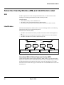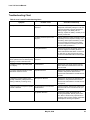
1
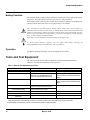
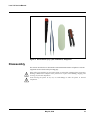
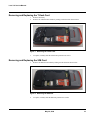
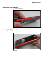
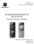
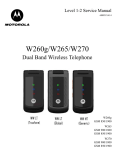
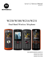
Level 1-2 Service Manual
6809518A97
W230/W388/W216/W231
Dual Band Wireless Telephone
W230/W388/W216/W231
GSM 900/1800
GSM 850/1900
Table of Contents
W230/W388/W216/W231
Table of Contents
Introduction ................................................................................................................................... 4
Product Identification ............................................................................................................ 4
Product Names ..................................................................................................................... 4
Product Changes .................................................................................................................. 4
Regulatory Agency Compliance ........................................................................................... 4
Computer Program Copyrights ............................................................................................. 5
About This Service Manual ................................................................................................... 5
Warranty Service Policy ....................................................................................................... 6
Parts Replacement ............................................................................................................... 7
Specifications ................................................................................................................................ 8
Product Overview ........................................................................................................................ 10
Features ............................................................................................................................. 10
General Functions ....................................................................................................................... 12
Controls, Indicators, and Input/Output (I/O) Connectors .................................................... 12
User Interface Menu Structure ........................................................................................... 14
Battery Function ................................................................................................................. 15
Operation ............................................................................................................................ 15
Tools and Test Equipment ......................................................................................................... 15
Disassembly ................................................................................................................................ 16
Removing and Replacing the Battery ................................................................................. 17
Removing and Replacing the T-flash Card ......................................................................... 18
Removing and Replacing the SIM Card ............................................................................. 18
Removing the audio jack cover .......................................................................................... 19
Removing the EMU jack cover ........................................................................................... 19
Removing and Replacing the Front Housing ...................................................................... 20
Removing and Replacing the Transceiver Board, Back Housing, and Vibrator Module .... 22
Removing the key frame ..................................................................................................... 23
Removing and Replacing the Antenna Module, Microphone ............................................. 23
Removing the board to board connector ............................................................................ 25
Removing and Replacing the LCD Screen ......................................................................... 25
Removing and Replacing the LCD Shielding Case ............................................................ 26
Removing and Replacing the Camera Module ................................................................... 27
Subscriber Identity Module (SIM) and Identification Label ..................................................... 29
SIM ..................................................................................................................................... 29
Identification ....................................................................................................................... 29
Troubleshooting .......................................................................................................................... 31
Manual Test Mode .............................................................................................................. 31
Manual Test Mode Commands .......................................................................................... 31
Troubleshooting Chart ........................................................................................................ 32
Programming: Software Upgrade and Flexing ................................................................... 33
Part Number Charts (W230) ........................................................................................................ 34
Exploded View Diagram ..................................................................................................... 34
Exploded View Parts List .................................................................................................... 35
2
May 30, 2008
Table of Contents
W230/W388/W216/W231
Part Number Charts (W388) ........................................................................................................ 36
Exploded View Diagram ..................................................................................................... 36
Exploded View Parts List .................................................................................................... 37
Part Number Charts (W216) ........................................................................................................ 38
Exploded View Diagram ..................................................................................................... 38
Exploded View Parts List .................................................................................................... 39
Part Number Charts (W231) ........................................................................................................ 40
Exploded View Diagram ..................................................................................................... 40
Exploded View Parts List .................................................................................................... 41
Accessories ........................................................................................................................ 42
Index ............................................................................................................................................... 1
3
May 30, 2008
Level 1-2 Service Manual
Introduction
Motorola® Inc. maintains a worldwide organization that is dedicated to provide responsive,
full-service customer support. Motorola products are serviced by an international network of
company-operated product care centers as well as authorized independent service firms.
Available on a contract basis, Motorola Inc. offers comprehensive maintenance and installation
programs that enable customers to meet requirements for reliable, continuous communications.
To learn more about the wide range of Motorola service programs, contact your local Motorola
products representative or the nearest Customer Service Manager.
Product Identification
The model number on a label (usually on the housing) identifies Motorola products. Use the
entire model number when inquiring about the product. Numbers are also assigned to chassis
and kits.
Use these numbers when requesting information or ordering replacement parts.
Product Names
Product names are listed on the front cover. Product names are subject to change without
notice. Some product names, as well as some frequency bands, are available only in certain
markets.
Product Changes
When electrical, mechanical or production changes are incorporated into Motorola products, a
revision letter is assigned to the chassis or kit affected, for example: -A, -B, or -C, and so on.
The chassis or kit number, complete with revision number is imprinted during production. The
revision letter is an integral part of the chassis or kit number and is also listed on schematic
diagrams, and printed circuit board layouts.
Regulatory Agency Compliance
This device complies with Part 15 of the FCC Rules. Operation is subject to the following
conditions:
•
•
This device may not cause any harmful interference, and
this device must accept interference received, including interference that may cause
undesired operation
This class B device also complies with all requirements of the Canadian Interference-Causing
Equipment Regulations (ICES-003).
Cet appareil numerique de la classe B respecte toutes les exigences du Reglement sur le
materiel brouilleur du Canada.
May 30, 2008
4
W230/W388/W216/W231
Computer Program Copyrights
The Motorola products described in this manual may include Motorola computer programs
stored in semiconductor memories or other media that are copyrighted with all rights reserved
worldwide to Motorola. Laws in the United States and other countries preserve for Motorola,
Inc. certain exclusive rights to the copyrighted Introduction computer programs, including the
exclusive right to copy, reproduce, modify, decompile, disassemble, and reverse-engineer the
Motorola computer programs in any manner or form without Motorola's prior written consent.
Furthermore, the purchase of Motorola products shall not be deemed to grant either directly or
by implication, estoppel, or otherwise, any license or rights under the copyrights, patents, or
patent applications of Motorola, except for a nonexclusive license to use the Motorola product
and the Motorola computer programs with the Motorola product.
About This Service Manual
Using this service manual and the suggestions contained in it assures proper installation,
operation, and maintenance of W230/W388/W216/W231 telephones. Refer questions about
this manual to the nearest Customer Service Manager. This manual contains mechanical
service information required for the equipment described and is current as of the printing date.
Audience
This document aids service personnel in testing and repairing W230/W388/W216/W231
telephones Service personnel should be familiar with electronic assembly, testing, and
troubleshooting methods, and with the operation and use of associated test equipment.
Scope
This manual provides basic information relating to W230/W388/W216/W231 telephones, and
also provides procedures and processes for repairing the units at Level 1 and 2 service centers,
including:
•
•
•
•
•
5
Unit swap out
Repairing of mechanical faults
Basic modular troubleshooting
Testing and verification of unit functionality
Initiate warranty claims and send faulty modules to Level 3 or 4 repair centers.
May 30, 2008
Level 1-2 Service Manual
Conventions
Special characters and typefaces, listed and described below, are used in this publication to
emphasize certain types of information.
Note: Emphasizes additional information pertinent to the subject matter.
Caution: Emphasizes information about actions that may result in equipment damage.
Waring: Emphasizes information about actions that may result in personal injury.
M
Keys to be pressed are represented graphically. For example, instead of "Press the Menu Key",
you will see "Press M".
Information from a screen is shown in text as similar as possible to what appears in the display.
For example, ALERTS or ALERTS.
Information that you need to type is printed in boldface type.
Warranty Service Policy
The product is sold with the standard 12-month warranty terms and conditions. Accidental
damage, misuse, and extended warranties offered by retailers are not supported under
warranty.
Non-warranty repairs are available at agreed fixed repair prices.
Out of Box Failure Policy
The standard out of box failure criteria applies. Customer phones that fail very early on after
the date of sale are to be returned to Manufacturing for root cause analysis, to guard against
epidemic criteria. Manufacturing to bear the costs of early life failure.
Product Support
The customer's original phones will be repaired but not refurbished as standard. Appointed
Motorola Service Hubs will perform warranty and non-warranty field service for level 2
(assemblies) and level 3 (limited Transceiver component). Motorola High Tech Centers will
perform level 4 (full component) repairs.
Customer Support
Customer support is available through dedicated Call Centers and in-country help desks.
Product-Service training should be arranged through the local Motorola Support Center.
May 30, 2008
6
W230/W388/W216/W231
Parts Replacement
When ordering replacement parts or equipment, include the Motorola part number and
description used in the service manual. When the Motorola part number of a component is not
known, use the product model number or other related major assembly along with a
description of the related major assembly and of the component in question. In the U.S.A., to
contact Motorola, Inc. on your TTY, call: 800-793-7834
Accessories and Aftermarket Division (AAD)
Replacement parts, test equipment, and manuals can be ordered from AAD.
U.S.A.
Outside U.S.A.
Phone: 800-422-4210
FAX: 800-622-6210
Phone: 847-538-8023
FAX: 847-576-3023
For EMEA spare parts call +49 461 803 1638.
For Asia spare parts call +65 648 62995.
7
May 30, 2008
Level 1-2 Service Manual
Specifications
General Functions
Specification
Dimensions
110.97mm x 45mm x 14.9mm
Weight
83g
LCD Display
65K Color CSTN,
Active Area: 28.79mm x 28.79mm,
Hardware pixels: 128 x 128
Band
GSM900/1800 or GSM850/PCS1900
Battery
940 mAh Li Ion Battery
Product type
BAR type
Antenna
Internal Antenna
Frequency Range (EGSM)
880-915 MHz Tx,
925-960 MHz Rx
Frequency Range (DCS)
1710 – 1785 MHz Tx,
1805-1880 MHz Rx
Frequency Range (GSM850)
824-849 MHz Tx,
869-894 MHz Rx
Frequency Range (PCS)
1850-1910MHz Tx,
1930-1990 MHz Rx
Channel Spacing
200KHz
Channels
174 EGSM, 374 DCS,
124 GSM850, 299 PCS
Modulation
GMSK at BT=0.3
Transmitter Phase Accuracy
5 Degrees RMS, 20 Degrees peak
Duplex spacing
45MHz EGSM, 95MHz DCS,
45MHz GSM850, 80MHz PCS
Frequency Stability
±0.1PPM of the downlink frequency (Rx)
Operating voltage
3.53V ~4.2V
Average Transmit Current
Power Level 5@DTX 50%: 175mA
Power Level 19@DTX 50%: 90mA
Average Standby Current
DRX2: 4mA
DRX9: 1.9mA
Temperature Range
-20°C to 55°C
Battery Life
Talk Time: 250~500 Mins;
Stand by Time: 150~300 Hours
Battery Charge Time
4 Hours to 90% of 940mAH capacity
Alert Volume
Max 95dB@ 5cm, 0.5 watts input
Transmitter Functions
Specification
RF Power Output
33 dBm typical GSM850/GSM900
30 dBm typical DCS1800/PCS1900
Output Impedance
50 ohms nominal
Spurious Emissions
-36 dBm from 0.1 to 1GHz,
-30 dBm from 1 to 4 GHz
May 30, 2008
8
W230/W388/W216/W231
Receiver Functions
Receiver Sensitivity
Specification
-107 dBm typical GSM 850/GSM900
-107 dBm typical DCS1800/PCS1900
RX Bit Error Rate (100K bits) type II
<2%
Channel Hop Time
500 microseconds
Time to Camp
Approximately 6~10 Second
Speech Coding Functions
Speech Coding Type
9
Specification
Regular pulse excitation/linear predictive
coding with long term prediction (PRE
LPC with LTP)
Bit Rate
13.0 Kbps
Frame Duration
20 ms
Block Length
260 bits
Classes
Class 1 bits =182 bits;
Class 2 bits = 78 bits
Bit Rate with FEC Encoding
22.8 Kbps
May 30, 2008
Level 1-2 Service Manual
Product Overview
The Motorola W230/W388/W216/W231 features a global system for mobile communications
wireless interface technology. It also features a simplified icon and graphical user interface
(UI) for easier operation in addition to short message service text messaging (SMS), speed
dialing, quick dialing, an alarm, a calculator, games, and an address book.
The telephones are made of polycarbonate plastic. The display and speaker, as well as the 21key keypad, transceiver printed circuit board (PCB), microphone, charger and headphone
connectors, and power button are contained within Bar form-factor housing. The Userreplaceable 940 mAh Lithium-Ion (Li-Ion) battery provide up to 250~500 Mins of talk time
with up to 150~300 Hours of standby time. The phone accepts 1.8V/3V mini subscriber
identity module (SIM) cards that fit into the SIM holder next to the battery. These telephones
feature a 128 x 128 pixel color graphics display and an internal antenna.
Features
W230/W388/W216/W231 telephones use advanced, self-contained, sealed, custom integrated
circuits to perform the complex functions required for GSM communication. Aside from the
space and weight advantage, microcircuits enhance basic reliability, simplify maintenance, and
provide a wide variety of operational functions.
Features available in this family of telephones include:
•
•
•
•
•
•
•
•
•
•
•
•
•
•
A 128 x 128 pixel color graphics display
Internal antenna
Lower voltage technology that provides increased standby and talk times
Extended GSM (EGSM) channels
Display animation
VibraCall® vibrating alert
5-Way navigation key
SIM Toolkit™ Class 2 (STK) (Network, subscription and SIM card or service provider
dependent feature. Not available in all areas.)
Backlight
Speed-, Quick- and One-Touch dialing
Call Forwarding and Holding
Customized Menus
Personal management tools calculator with currency converter, and clock with date
Other features
May 30, 2008
10
W230/W388/W216/W231
Caller Line Identification
Upon receipt of a call, the calling party's phone number is compared to the phone book. If the
number matches a phone book entry, that name will be displayed. If there is no phone book
entry, the incoming phone number will be displayed. In the event that no caller identification
information is available, an incoming call message is displayed.
SIM Toolkit™ - Class 2
SIM Application Toolkit is a value-added service delivery mechanism that allows GSM
operators to customize the services they offer their customers, from the occasional user who
requests sports news and traffic alerts, to a high call time business user who receives stock
alerts and checks flight times. Operators can now create their own value-added services menu
quickly and easily in the phone.
The customized menu will appear as the first menu and may be updated over-the-air with new
services when customers request them.
Harvey_ Comparison Chart
11
Harvey
Band
VGA
LCM
FM Radio
FLASH
W230
GSM 900/1800, GSM 850/1900
NO
1.6 CSTN
YES
128/64
W388
GSM 900/1800, GSM 850/1900
YES
1.8 TFT
YES
256/128
W216
GSM 900/1800, GSM 850/1900
NO
1.6 CSTN
NO
128/64
W231
GSM 900/1800, GSM 850/1900
NO
1.6 CSTN
YES
128/64
May 30, 2008
Level 1-2 Service Manual
General Functions
Controls, Indicators, and Input/Output (I/O) Connectors
The W230/W388/W216/W231 phone's controls are located on the front side of the device and
on the keyboard as shown in below. Indicators icons are displayed on the LCD.
Listen to music
Change phone, connect
to computer
Left Soft Key
Right Soft Key
Send Key
Power/End Key
Centre Key
Navigation Key
Microphone
Press & hold
the Power
Key O until
the display
lights up to
turn on your
phone.
Press the
Navigation
Key S up/
down/left/
right to
highlight a
menu
feature.
Press the
Center Key
s to open
the Main
Menu.
Press the
Center Key
s to select
it.
Figure 1. W230/W388/W216/W231 Telephone Control Locations
Menu Navigation
W230/W388/W216/W231 telephones are equipped with a simplified icon and graphical-based
user interface. See the table below for details of the W230/W388/W216/W231 menu structure. A
five-way navigation key allows you to move easily through menus and confirm your selection.
May 30, 2008
12
W230/W388/W216/W231
Liquid Crystal Display (LCD)
The LCD provides a 700 square millimeter multicolor backlit color display with useradjustable contrast settings for optimum readability in all light conditions. The bit-map 128 x
128 pixel display includes up to 3 lines of text, 1 line of icons, and 1 line of prompts.
When you turn on your phone, it displays the home screen. To dial a number from the
home screen, press number keys and O.
Note: Your home screen might look a little different from this example.
Left Soft Key Label
Right Soft Key Label
Soft key labels show the current soft key functions.
For soft key locations, see page 2.
Press the navigation key S up, down, left, or right to select items in the home screen.
Status indicators can appear across the top of the home screen:
indicator
6
Signal Strength
Vertical bars show the strength of the network connection.
,
Roaming
Indicates phone is in a digital coverage area and is roaming off
network.
Missed Call
Indicates that you received an unanswered call.
O
Voice Call/
Incoming Call
Shows during an active voice call.
E
Battery Level
Shows battery charge level. The more bars, the greater the
charge.
õ
Loud Ring
Indicates Style (in Ring Styles) is set to Loud.
ô
Í
Soft Ring
Indicates Style (in Ring Styles) is set to Soft.
All Sounds Off
Indicates Style (in Ring Styles) is set to Silent.
ö
Vibrate then
Ring
Indicates Style (in Ring Styles) is set to Vibe then Ring.
Î
Vibrate
Indicates Style (in Ring Styles) is set to Vibrate.
Indicates speakerphone is on.
Spkrphone On
New Text
Message
Appears when you receive a new text message.
New Voicemail
Message
Appears when you receive a new voicemail message.
Figure 2. W230/W388/W216/W231 Display Icon Indicators
13
May 30, 2008
Level 1-2 Service Manual
User Interface Menu Structure
The table below shows a portion of the W230/W388/W216/W231 telephone menu structure.
* Optional Network, SIM card, or subscription-dependent features.
Menu Map
main menu
É
n Contacts
s
Recent calls
• Received calls
• Dialed calls
• Notepad
• Call times
• Call cost *
• Data times
• Data volumes
e Messages
• Create
• Inbox
• Drafts
• Outbox
• Quick notes
• Voicemail
• Browser msgs
• Info services
• MMS templates
Extras
Calculator
MyMenu
Alarm clock
Stop watch
Chat*
Dialling services*
STK*
Calendar
Phone Inspector
Q Games
• Java
• Games
á WebAccess
• Start browser
• Web shortcut
• Go to URL
• Web session
• Stored pages
• History
• General setting
•
•
•
•
•
•
•
•
•
settings menu
Easy menu
Ring Style
• Style
• Style detail
H Call divert
• Voice calls
• Fax calls*
• Data calls*
• Cancel all
• Divert status
In Call Setup
• In-Call Timer
• Call Cost Setup
• My Caller ID
• Answer Options
• Call Waiting
• Hearing Aid*
w Initial Setup
• Time and Date
• Auto Redial
• Display settings
• Backlight
• Scroll
• Language
t
•
•
•
•
•
DTMF
TTY Setup*
Master reset
Master clear
Format additional
storage device
m Phone Status
• My numbers
• Active line*
• Battery metre
S Headset
• Auto Answer
Airplane Mode
• Airplane Mode
• Prompt At Startup
j Network
• New Network
• Network Setup
• Avail. Networks
• My Network List
• Service Tone
• Call Drop Tone
• Band Selection
h Multimedia
•
•
•
•
•
Camera
Pictures
Sounds
Music
FM radio
l
Personalize
Home Screen
Main menu
Colour Setting
Greeting
Wallpaper
Screensaver
Speed Dial
w Settings
• (see next page)
•
•
•
•
•
•
•
* Network Dependent
This is the standard main
menu layout.
Your phone’s menu may
be a little different.
Security
Phone Lock
Lock Keypad
Auto Key Lock
Fixed Dial*
Call Barring
SIM PIN
New Passwords
Restrict Calls
Block List
Easy Prefix
• Auto Change*
• Pref.Op*
Java Settings
• Java System
• InvisibeNET
• Delete All Apps
• App Backlight
• App App Vibration
• App Volume
•
•
•
•
•
•
•
•
•
* Network Dependent
Figure 3. W230/W388/W216/W231 Menu Structure
May 30, 2008
14
W230/W388/W216/W231
Battery Function
The telephone displays a battery charge indicator icon in the idle screen to indicate the battery
charge level. The gauge shows four levels: 50%, 20%, 5%, and Low Battery.
Removing the battery causes the phone to shut down immediately and loose any pending work
(partially entered phone book entries or outgoing messages, for example).
Note: All batteries can cause property damage and/or bodily injury such as burns if a
conductive material such as jewelry, keys, or beaded chains touches exposed terminals. The
conductive material may complete an electrical circuit (short circuit) and become quite hot.
Exercise care in handling any charged battery, particularly when placing it inside a pocket,
purse, or other container with metal objects.
If the battery is removed while receiving a message, the message is lost.
To ensure proper memory retention, turn the phone OFF before removing the
battery.Immediately replace the old battery with a fresh battery.
Operation
For detailed operating instructions, refer to the appropriate User Guide.
Tools and Test Equipment
The table below lists the tools and test equipment used on W230/W388/W216/W231
telephones. Use either the listed items or the equivalent.
Table 1: General Test Equipment and Tools
Motorola Part Number1
Description
Application
See Table 3
Charger
Used to charge battery and power phone
0180386A82
Antistatic Mat Kit (includes 66-80387A95
antistatic mat, 66-80334B36 ground
cord, and 42-80385A59 wrist band)
Provides protection from damage to
phone caused by electrostatic discharge
(ESD)
Antistatic Gloves
Provides protection from damage to
phone caused by electrostatic discharge
(ESD)
0-00-00-3005 (AMS)
Disassembly tool, plastic with flat and
pointed ends (manual opening tool)
Used during assembly/disassembly
0-00-00-40861 (AMS)
Camera disassembly Jig tool
-
6680388B01
HP34401A
2
Tweezers, plastic
Used during assembly/disassembly
T5 Screw driver
Used with Screw Driver
Digital Multimeter
Used to measure battery voltage
1. To order in North America, contact Motorola Aftermarket and Accessories Division (AAD) by phone at (800) 422-4210 or
FAX (800) 622-6210. Internationally, AAD can be reached by calling (847) 538-8023 or by fax (847) 576-3023.
2. Not available from Motorola. To order, contact Hewlett Packard at (800) 452-4844.
15
May 30, 2008
Level 1-2 Service Manual
Figure 4. A screwdriver (T5), a pair of tweezers, wedge tool
Disassembly
This section describes how to disassemble a W230/W388/W216/W231 telephone. Tools and
equipment used are listed on the preceding page.
Many of the integrated devices used in this phone are vulnerable to damage from electrostatic
discharge (ESD). Ensure adequate static protection is in place when handling, shipping, and
servicing any internal components.
Avoid stressing the plastic in any way to avoid damage to either the plastic or internal
components.
May 30, 2008
16
W230/W388/W216/W231
Removing and Replacing the Battery
All batteries can cause property damage and/or bodily injury such as burns if a conductive
material such as jewelry, keys, or beaded chains touches exposed terminals. The conductive
material may complete an electrical circuit (short circuit) and become quite hot. Exercise care
in handling any charged battery, particularly when placing it inside a pocket, purse, or other
container with metal objects.
1.
2.
Ensure the phone is turned off.
Push the latch and pop out the battery cover.
Figure 5. Removing the battery cover
3.
Press the tab to pop out the battery.
There is a danger of explosion if the Lithium ion battery is replaced incorrectly. Replace only
with the same type of battery or equivalent as recommended by the battery manufacturer.
Dispose of used batteries according to the manufacturer's instructions.
4.
To replace, insert the battery with 2 tabs on its bottom end into the battery slot.
Figure 6. Replace the battery cover
5.
17
Click the battery into place, then slip the battery cover over it.
May 30, 2008
Level 1-2 Service Manual
Removing and Replacing the T-flash Card
1.
2.
Remove the battery.
Remove the T-flash from its holder by sliding it in the direction shown below.
Figure 7. Removing the T-flash card
3.
To replace, carefully slide the T-flash into position in its socket.
Removing and Replacing the SIM Card
1.
Remove the SIM from its holder by sliding it in the direction shown below.
Figure 8. Removing the SIM card
2.
To replace, carefully slide the SIM into position in its socket.
May 30, 2008
18
W230/W388/W216/W231
Removing the audio jack cover
1.
Remove the audio jack cover.
Figure 9.
Removing the EMU jack cover
1.
Remove the EMU jack cover.
Figure 10.
19
May 30, 2008
Level 1-2 Service Manual
Removing and Replacing the Front Housing
1.
Pull open the top of the front housing.
Figure 11.
2.
Remove the front housing.
Figure 12. Removing the front housing
May 30, 2008
20
W230/W388/W216/W231
3.
(Optional) Remove and replace the rubber keypad. It slips out of the front housing.
Figure 13. Removing the rubber keypad
4.
To replace, simply snap the front and back halves together again.
5.
6.
Remove six T5 screws around the rear housing.
Use torque force of 13.73 N-cm.
Figure 14. Removing the six T5 screws
21
May 30, 2008
Level 1-2 Service Manual
Removing and Replacing the Transceiver Board, Back Housing, and Vibrator
Module
1.
2.
Remove the front housing.
Disengage the both side hooks which help to secure the transceiver board to the rear
housing, and then pop it out.
Figure 15. Disengaging the side hooks
3.
In the rear housing component, gently pry out the vibrator module.
Figure 16. Removing the vibrator module
May 30, 2008
22
W230/W388/W216/W231
Removing the key frame
1.
Remove the key frame.
Figure 17.
Removing and Replacing the Antenna Module, Microphone
1.
2.
Remove the transceiver board, the vibrator module, and the rear housing.
Gently snap the antenna away from the transceiver board.
Figure 18. Removing the antenna module
23
May 30, 2008
Level 1-2 Service Manual
3.
(Optional) Remove and replace the speak.
Figure 19. Removing the microphone
4.
Carefully pry off the microphone component.
Figure 20. Removing the microphone
May 30, 2008
24
W230/W388/W216/W231
Removing the board to board connector
1.
Removing the board to board connector.
Figure 21.
Removing and Replacing the LCD Screen
1.
2.
Remove the antenna module as described earlier.
Gently pry the LCD screen away from the Transceiver board. Six hooks hold it in place
(three on each side).
Figure 22. Pry the LCD screen away from the Transceiver board
3.
4.
5.
25
Detach the cable connecting the LCD screen to the Transceiver board.
To replace it, gently solder the cable to the Transceiver board then mount the LCD.
Restore the antenna module and other parts.
May 30, 2008
Level 1-2 Service Manual
Removing and Replacing the LCD Shielding Case
1.
2.
Remove the LCD screen as described earlier.
Gently pry the LCD shielding case away from the LCD screen.
Shielding case
Figure 23. Pry the LCD shielding case away
3.
(Optional) Remove and Replace the receiver.
Figure 24. Pop out the receiver
4.
5.
To replace it, mount the LCD shielding case over the LCD screen.
Restore the LCD screen and other parts.
May 30, 2008
26
W230/W388/W216/W231
Removing and Replacing the Camera Module
1.
Remove the gasket of Camera.
Figure 25. Remove the gasket of Camera
2.
Use Jig to clip out the camera module gently.
Notice: Please use Jig (AMS PN: 0-00-00-40861 /CCI PN:
XXXX005700W) to remove Camera module.
Figure 26. Use Jig to clip out the camera module gently
27
May 30, 2008
Level 1-2 Service Manual
3.
(Optional) remove and replace the camera module.
Figure 27. Remove the camera module
4.
Restore the camera module and other parts.
May 30, 2008
28
W230/W388/W216/W231
Subscriber Identity Module (SIM) and Identification Label
SIM
A SIM is required to access the existing local GSM network, or remote networks when
traveling (if a roaming agreement has been made with the provider).
The SIM contains:
•
•
•
All the data necessary to access GSM services
The ability to store user information such as phone numbers
All information required by the network provider to provide access to the network
Identification
Each Motorola GSM phone is labeled with a variety of identifying numbers. The following
information describes the current identifying labels.
Mechanical Serial Number (MSN)
•
•
•
The MSN is an individual unit identity number and remains with the unit throughout its
life.
The MSN can be used to log and track a phone on Motorola's Service Center Database.
The MSN is divided into 4 sections as shown in Figure 28.
MSN 10 Digits
3 Digits
1 Digit
2 Digits
4 Digits
APC
DC
DC
SNR
Account Product Code
i.e. StarTACTM Phone130
Distribution Center
i.e. Easter Inch
Date Code: Year and
Month of Shipment
Unit's individual serial
number
Figure 28. MSN Label Breakdown
International Mobile Station Equipment Identity (IMEI)
The International Mobile Station Equipment Identity (IMEI) number is an individual number
unique to the Transceiver and is stored within the unit's memory. The IMEI uniquely identifies
an individual mobile station and thereby provides a means for controlling access to GSM
networks based on mobile station types or individual units. The full IMEI structure is listed in
the table below.
29
May 30, 2008
Level 1-2 Service Manual
Table 2: IMEI Number Breakdown
TAC
NNXXXXXX
Serial Number
ZZZZZZ
Check Digit
A
Where
TAC
Type Allocation Code, formerly known as Type Approval Code
NN
Reporting Body Identifier (BABT or CTIA)
XXXXXX
Type Identifier (defined by BABT or CTIA)
ZZZZZZ
Individual unit serial number
A
Phase 1 = 0.
Phase 2 & 2+= check digit and is defined as a function of
all other IMEI digits
Other label number configurations present are:
•
•
TRANSCEIVER NUMBER: Identifies the product type. Normally the SWF number. (i.e.
V100).
PACKAGE NUMBER: Identifies the equipment type, mode, and language in which the
product is shipped.
May 30, 2008
30
W230/W388/W216/W231
Troubleshooting
Manual Test Mode
Motorola W230/W388/W216/W231 telephones are equipped with a manual test mode
capability. This allows service personnel to verify functionality and perform fault isolation by
entering keypad commands.
To enter the manual test command mode, a GSM/DCS/PCS test SIM must be used.
1.
2.
3.
4.
5.
Press and hold
to turn the phone OFF.
Remove the battery as described in the procedures.
Remove the customer’s SIM card from the phone as described in the procedures.
Insert the test SIM into the SIM slot.
Replace the battery as described in the procedures.
6.
Press and hold
to turn the phone ON.
Manual Test Mode Commands
Table 3: Manual Test Commands
Key Sequence
#02#
Handset information
#03#
RF information
#04#
ADC information
#09#
Simple Test mode
**0102#
FFS format
**0105#
Disable EFEM mode
*#06#
31
Test Function/Name
IMEI number
May 30, 2008
Remarks
Level 1-2 Service Manual
Troubleshooting Chart
Table 4: Level 1 and 2 Troubleshooting Chart
Symptom
1. Telephone will not turn on or stay on.
Probable Cause
Verification and Remedy
a) Battery either discharged or
defective.
Measure battery voltage across a 50 ohm (>1
Watt) load. If the battery voltage is <3.25 Vdc,
recharge the battery using the appropriate
battery charger. If the battery will not
recharge, replace the battery. If battery is not
at fault, proceed to b.
b) Battery terminals open or misaligned.
Visually inspect the battery terminals on both
the battery and the telephone. Realign and, if
necessary, either replace the battery or refer
to a Level 3 Service Center for the battery
connector replacement. If battery terminals
are not at fault, proceed to c.
c) keypad defective.
Replace the keypad. Temporarily connect a
+3.6 Vdc supply to the battery terminals.
Press and hold the PWR button. If unit turns
on and stays on, disconnect the dc power
source and reassemble with the new keypad.
2. Telephone exhibits poor reception or
erratic operation such as calls frequently
dropping or weak or distorted audio.
Connections to or from lower PCB
defective.
Check connection between the antenna and
the lower PCB.
3. Display is erratic, or provides partial
or no display.
LCM defective.
Replace the LCM. Verify that the fault has
been cleared and reassemble the unit with
the new LCM.
4. Incoming call alert transducer audio
distorted or volume is too low.
Speaker defective.
Replace the speaker as described in the procedures. Verify that the fault has been
cleared and reassemble the unit with the new
speaker.
5. Telephone transmit audio is weak.
(usually indicated by called parties complaining of difficulty in hearing voice).
Microphone defective.
Replace the microphone as described in the
procedures. Verify that the fault has been
cleared and reassemble the unit with the new
microphone.
6. Receive audio from earpiece speaker
is weak or distorted.
a) Connections to or from lower
PCB defective.
Check connection between the antenna and
the lower PCB. If the connection is OK, proceed to b.
b) Speaker defective.
Temporarily replace the speaker with a
known good speaker. Ensure good connection. Place a call and verify improvement in
earpiece audio. If fault is cleared, reassemble
the telephone with the good speaker.
May 30, 2008
32
W230/W388/W216/W231
Table 4: Level 1 and 2 Troubleshooting Chart (Continued)
Symptom
Probable Cause
Verification and Remedy
7. Telephone will not recognize or accept
SIM card.
SIM card defective.
Check the SIM card contacts for dirt. Clean if
necessary, and check if fault has been
cleared. If the contacts are clean, insert a
known good SIM card into the telephone.
Power up the unit and confirm that the card
has been accepted. If the fault no longer
exists, replace the defective SIM card.
8. Keypad not functioning.
Keypad defective.
Use alcohol to wipe the keypad metal dome.
Check if fault has been cleared. If the fault is
still present, either replace the keypad or
refer to a Level 3 Service Center for the keypad metal dome replacement.
9. Vibrator feature not functioning.
a) Vibrator faulty.
Check general condition of vibrator. If it is
good, proceed to b.
b) Vibrator defective.
Replace the defective vibrator.
Headset plug not fully pushed.
Ensure the headset plug is fully seated in the
jack.
10. No or weak audio when using headset.
Programming: Software Upgrade and Flexing
Contact your local technical support engineer for information about equipment and procedures
for flashing and flexing.
33
May 30, 2008
Level 1-2 Service Manual
Part Number Charts (W230)
The following section provides a reference for the parts associated with W230 telephones.
Exploded View Diagram
Figure 29. W230 Exploded View Diagram
May 30, 2008
34
W230/W388/W216/W231
Exploded View Parts List
Table 5: W230 Exploded View Parts List
Part Number
35
Item Number
Description
Specification
001
7630121256W
LCM
WD-Y1212VC-6CLW 128*128 WINTEK
002
2240133209W
RECEIVER
SDR1332F-S2-FB5-G AAC
003
3930507104W
SPR-VIB
ψ5*L7.15 1.3V NEBG-MC3 SHICOH
004
2220601502W
MIC
ACMG6015-03P22-213 -41dB AAC
005
2250160808W
SPEAKER
DMS1608F-05-PC-F1B-G 8ohm AAC
006
2300H38001W
I-ANTENNA
H38 ANT+HOLDER EU
051
82E5800003W
LABEL
E58 WATERPROOF 3M5559ψ4mm
251
6911120001W
F/WMB 33
H38 GA-144
300
5501780001W
ME/PT 33
H38 MANDARIN
301
2545H38001W
MARK
H38-ABS-CHROME-M-LOGO
302
2541H38003W
LCD-LENS
H38-MR58-0.8MM-BLACK
303
2511H38001W
UPP-ASSY
H38-SILVER
304
3104H38011W
DIAL-KEY
H38-P+R-BLACK-E-21KEY
305
3012H38001W
SHIELDASY
H38-LCM-BRACK+SPONGE ASSY
306
254BH38001W
PLATE
H38-PC-KEYPAD
307
3109H38001W
MET-DOME
H38-ψ4*160g-21KEY
308
302FH38001W
SPK-GASKE
H38-RUBBER-39.2*24.4*2.8-SPK
309
3064H38002W
MYLAR
H38-MYLAR-ON-RF
310
303EH38001W
SPK-SPON
H38-PORON-12.4*9.4*1.05T
311
3061H38004W
DUST-PRO
H38-MESH-6.5*22-SPK
312
3064H38001W
MYLAR
H38-PC-8.14*3.09*0.08T
313
2512H38001W
LOW-ASSY
H38-LICORICE
314
3028H38001W
RF-COV
H38-RUBBER-LICORICE
315
3062H38001W
NAMEPLATE
H38-PC-BLACK
316
302BH38001W
RUBBERPAD
H38-TPU-15.21*7-AUDIO-LICORICE
317
302BH38002W
RUBBERPAD
H38-TPU-15.21*7-EMU-LICORICE
318
303MH38001W
SPONGE
H38-PORON-9.7*7.7*1-MB BTB
385
3501750102W
SCREW_G
TORX M1.7*5.0-BLACK-NI KL
May 30, 2008
Level 1-2 Service Manual
Part Number Charts (W388)
The following section provides a reference for the parts associated with W388 telephones.
Exploded View Diagram
Figure 30. W388 Exploded View Diagram
May 30, 2008
36
W230/W388/W216/W231
Exploded View Parts List
Table 6: W388 Exploded View Parts List
37
Part Number
Item Number
Description
Specification
001
763000189GW
LCM
990000214 128*160 TPO
002
2240071103W
RECEIVER
SDRP0711KJ01-F2-G AAC
003
2220432301W
MIC
KUF4323-013220 ψ 6*1.5 -41dB
004
3930507104W
SPR-VI
ψ 5*L7.15 1.3V NEBG-MC3 SHICOH
005
2250160808W
SPEAKER
DMS1608F-05-PC-F1B-G 8ohm AAC
006
2300H38001W
I-ANTENNA
H38 ANT+HOLDER EU
007
7650600301W
CMOS SENS
CCS600320V03850L VGA 6*6*4.97C
008
82E5800003W
LABEL
E58 WATERPROOF 3M5559 f 4mm
251
6911190001W
F/WMB 33
M83 GA-165
300
5501870001W
ME/PT 33
M83 BLACK/SLATE
301
2545M83001W
MARK
M83-ABS-DARK CHROME-M-LOGO
302
2541M83001W
LCD-LENS
M83-MR58-CLEAR BLACK
303
2511M83001W
UPP-ASSY
M83-BLACK SLATE
304
3104M83011W
DIAL-KEY
M83-P+R-BLK-E-21KEY RED R
305
3109M83001W
MET-DOME
M83-f 4*160g-21KEY
306
3012M83001W
SHIELDASY
M83-LCM-BRACK+SPONGE ASSY
307
303MH38001W
SPONGE
H38-SRS40P-MB BT
308
3068M83001W
GASKET
M83-RUBBER-CMOS
309
302FH38001W
SPK-GASKE
H38-RUBBER-ANTENNA HOLDER
310
303EH38001W
SPK-SPON
H38-SRS40P-SPEAKER
311
3061M83006W
DUST-PRO
M83-MESH-SPK-RED
312
3061M83005W
DUST-PRO
M83-MESH-3RD-REC-RED
313
3064M83001W
MYLAR
M83-PC-LANYARD
314
302BM83001W
RUBBERPAD
M83-TPU-AUDIO-BLACK
315
302BM83002W
RUBBERPAD
M83-TPU-EMU-BLACK
316
2512M83001W
LOW-ASSY
M83-BLACK
317
3028M83002W
RF-COV
M83-SILICON-BLACK
318
254GM83003W
CMOS-LENS
M83-MR58-CLEAR RED
319
254CM83001W
SCREW-COV
M83-SILICON-BLACK
320
3062M83001W
NAMEPLATE
M83-PC-BLACK W388
385
3501755102W
SCREW_G
FPH T5-M1.7*5.5-BLACK-SAE 1018
May 30, 2008
Level 1-2 Service Manual
Part Number Charts (W216)
The following section provides a reference for the parts associated with W216 telephones.
Exploded View Diagram
Figure 31. W216 Exploded View Diagram
May 30, 2008
38
W230/W388/W216/W231
Exploded View Parts List
Table 7: W216 Exploded View Parts List
Part Number
39
Item Number
Description
Specification
001
7630121256W
LCM
WD-Y1212VC-6CLW 128*128 WINTEK
002
2240133209W
RECEIVER
SDR1332F-S2-FB5-G AAC
003
3930507104W
SPR-VIB
ψ5*L7.15 1.3V NEBG-MC3 SHICOH
004
2220601502W
MIC
ACMG6015-03P22-213 -41dB AAC
005
2250160808W
SPEAKER
DMS1608F-05-PC-F1B-G 8ohm AAC
006
2300H38001W
I-ANTENNA
H38 ANT+HOLDER EU
007
8701000034W
PE BAG
H38 W/O TALC 70*160mm
008
82E5800003W
LABEL
E58 WATERPROOF 3M5559 ψ4mm
009
82E7200001W
LABEL
E72 3C LABEL FOR PRC
010
82H8000003W
LABEL
H80 CMM LOGO FOR PRC
251
6911120041N
F/WMB 33
M51 GA-144
300
550193H001N
ME/PT 33
M51 LICORICE DK-MC CMCC
301
2545M51001W
MARK
M51-ABS-BLACK-M-LOGO
302
2541M51001W
LCD-LENS
M51-MR58-0.8MM-BLACK-CMCC
303
2511H38002W
UPP-ASSY
H38-LICORICE
304
3104M51031W
DIAL-KEY
M51-P+R-BLACK_SLATE-MC-21KEY
305
3012H38001W
SHIELDASY
H38-I CHIUN-LCM SHD ASSY
306
254BH38001W
PLATE
H38-PC-KEYPAD
307
3109H38001W
MET-DOME
H38-ψ4*160g-21KEY
308
302FH38001W
SPK-GASKE
H38-RUBBER-ANTENNA HOLDER
310
303EH38001W
SPK-SPON
H38-SRS40P-SPEAKER
311
3061H38004W
DUST-PRO
H38-MESH-SPK
312
3064H38001W
MYLAR
H38-PC-LANYARD
313
2512H38001W
LOW-ASSY
H38-LICORICE
314
3028H38001W
RF-COV
H38-RUBBER-LICORICE
315
3062H38003W
NAMEPLATE
H38-PC-BLACK-CMCC
316
302BH38001W
RUBBERPAD
H38-TPU-15.21*7-AUDIO-LICORICE
317
302BH38002W
RUBBERPAD
H38-TPU-15.21*7-EMU-LICORICE
318
303MH38001W
SPONGE
H38-SRS40P-MB BTB
319
3064M51001W
MYLAR
M51-PC-T_FLASH
385
3501750102W
SCREW_G
TORX M1.7*5.0-BLACK-NI KL
May 30, 2008
Level 1-2 Service Manual
Part Number Charts (W231)
The following section provides a reference for the parts associated with W231 telephones.
Exploded View Diagram
Figure 32. W231 Exploded View Diagram
May 30, 2008
40
W230/W388/W216/W231
Exploded View Parts List
Table 8: W231 Exploded View Parts List
Part Number
Item Number
Description
Specification
001
2240133209W
RECEIVER
SDR1332F-S2-FB5-G AAC
002
7630121256W
LCM
WD-Y1212VC-6CLW 128*128 WINTEK
003
2220601502W
MIC
ACMG6015-03P22-213 -41dB AAC
004
3930507104W
SPR-VIB
ψ5*L7.15 1.3V NEBG-MC3 SHICOH
005
2250160808W
SPEAKER
DMS1608F-05-PC-F1B-G 8ohm AAC
006
2300H38001W
I-ANTENNA
H38 ANT+HOLDER EU
007
8701000029W
PE BAG
H80 W/O TALC 70*190MM
008
82E5800003W
LABEL
E58 WATERPROOF 3M5559 ψ4mm
251
6911120001N
F/WMB 33
H38 GA-144
300
5501960101N
ME/PT 33
M55 LICORICE/MANDARIN
301
2545H38001W
MARK
H38-ABS-CHROME-M-LOGO
302
2541M55001W
LCD-LENS
M55-MR58-0.8MM-BLACK SLATE
303
2511M55002W
UPP-ASSY
M55-LICORICE WITH MANDARIN
304
3104M55012W
DIAL-KEY
M55-P+R-LICORICE-E-21KEY
305
3012H38001W
SHIELDASY
H38-I CHIUN-LCM SHD ASSY
306
254BH38001W
PLATE
H38-PC-KEYPAD
307
3109H38001W
MET-DOME
H38-ψ4*160g-21KEY
308
302FH38001W
SPK-GASKE
H38-RUBBER-ANTENNA HOLDER
309
303MH38001W
SPONGE
H38-SRS40P-MB BTB
310
303EH38001W
SPK-SPON
H38-SRS40P-SPEAKER
311
3061H38004W
DUST-PRO
H38-MESH-SPK
312
3064H38001W
MYLAR
H38-PC-LANYARD
313
2512H38001W
LOW-ASSY
H38-LICORICE
314
3028H38001W
RF-COV
H38-RUBBER-LICORICE
315
3062M55001W
NAMEPLATE
M55-PC-BLACK
316
302BH38001W
RUBBERPAD
H38-TPU-15.21*7-AUDIO-LICORICE
317
302BH38002W
RUBBERPAD
H38-TPU-15.21*7-EMU-LICORICE
385
3501750102W
SCREW_G
TORX M1.7*5.0-BLACK-NI KL
There is a danger of explosion if the Lithium ion battery pack is replaced incorrectly. Replace
only with the same type of battery or equivalent as recommended by the battery manufacturer.
Dispose of used batteries according to the manufacturer's instructions.
To order parts please use the following Link:
https://servicelink3.motorola.com
(Password is required)
For information on ordering parts please contact EMEA at +49 461 803 1638.
41
May 30, 2008
Level 1-2 Service Manual
Accessories
Table 9: List of Accessories
Description
Mini-USB plug Accessories
EMU Switch Mode Midrate (PRC)
EMU Switch Mode Midrate (US)
EMU Switch Mode Midrate (Taiwan)
EMU Switch Mode Midrate (Euro)
EMU Switch Mode Midrate (HK/UK)
EMU Switch Mode Midrate (Australia)
EMU Switch Mode Midrate (India)
EMU Switch Mode Midrate (Mexico)
EMU Switch Mode Midrate (Brazil)
EMU Switch Mode Midrate (Arg)
EMU Switch Mode Midrate (Japan)
EMU Switch Mode Midrate (Korea)
EMU Switch Mode Dual Rate (Brazil)
EMU Switch Mode Dual Rate (Arg)
EMU Switch Mode Dual Rate (PRC)
EMU Switch Mode Dual Rate (HK)
EMU Switch Mode Dual Rate (Mex)
EMU Switch Mode Dual Rate (US)
EMU Switch Mode Dual Rate (Twn)
EMU Switch Mode Dual Rate (Japan)
P790 Portable Charger
Charger Adapter
Charger Adapter °V Aust / NZ Plug
Charger Adapter °V Euro Plug
Charger Adapter °V UK Plug
Travel Charger BASE ONLY Standard- PRC
COMMON USBA
Data Cable Mini USB/USB/Serial
512MB microSD card & Mot SD adapter
1GB microSD card & Mot SD adapter
2GB microSD card & Mot SD adapter
In-Vehicle Accessories
Hi Performance VPA
P310 EMU MidRate
VC700 EMU Power Adapter
Audio Accessories
Mono Earbud Headset (Black)
S212 Wired Stereo HS (2.5mm barrel)
Headset One Touch w/ Send-End
Stereo One-Touch Earbud
Batteries
Battery BQ50 Li-Ion 940 mAh
May 30, 2008
Part Number
SPN5188
SPN5185
SPN5216
SPN5189
SPN5190
SPN5193
SPN5194
SPN5186
SPN5187
SPN5192
SPN5274
SPN5351
SPN5196
SPN5197
SPN5198
SPN5199
SPN5200
SPN5202
SPN5270
SPN5275
SPN5353
SYN8127
SYN7456
SYN7455
SPN5440A
SKN6371x
SKN6253
SYN1405
SYN1406
SYN1407
SPN5401
SYN1630
SYN0847
SYN8390
SYN1462
SYN8419
CHYN4516
SNN5804A
42
Level 1-2 Service Manual
Index
Index
A
About
Audience 5
Conventions 6
Scope 5
Accessories and Aftermarket Division 7
Audience 5
B
Back Housing
Removing and Replacing 22
Battery
Disposal 17
Function 15
Operation 15
Removing and Replacing 17
C
Caller Line Identification 11
Controls 12
Conventions 6
Customer Support 6
D
Disassembly 16
E
Electrostatic Discharge 16
F
Front Housing
Removing and Replacing 19, 20
G
General Functions 12
H
Headset Connector Port 12
May 30, 2008
Index-1
Index
W230/W388/W216/W231
I
Indicators 12
Input/Output (I/O) Connectors 12
International Mobile Station Equipment Identity (IMEI) 29
Number Breakdown 29
L
LCD Shielding Case
Removing and Replacing 26, 27
Left Soft Key 12
Liquid Crystal Display (LCD) 13
LCD Shielding Case 26
Removing and Replacing 25
M
Mechanical Serial Number 29
Menu Key 12
Menu Navigation 12
Microphone 12
N
Navigation Key 12
O
Out of Box Failure Policy 6
P
Part Number Charts 34
Parts Replacement 7
Accessories and Aftermarket Division 7
Power Connector Port 12
Power/End Key 12
Product Overview 10
Caller Line Identification 11
Features 10
SIM Toolkit™ - Class 2 11
Product Support 6
R
Right Soft Key 12
S
Scope 5
Send/Answer Key 12
Signal Strength Indicator 13
SIM Card 29
Index-2
May 30, 2008
Level 1-2 Service Manual
Index
Identification Label 29
International Mobile Station Equipment Identity (IMEI) 29
Mechanical Serial Number 29
Removing and Replacing 18
SIM Toolkit™ - Class 2 11
Specifications 8
T
Troubleshooting 31
U
USB Connector Port 12
User Interface Menu Structure 14
V
Vibrator Motor
Removing and Replacing 23
W
Warranty Service Policy 6
Customer Support 6
Out of Box Failure Policy 6
Product Support 6
May 30, 2008
Index-3
Index
Index-4
W230/W388/W216/W231
May 30, 2008
MOTOROLA, the Stylized M Logo, and all other trademarks indicated as such herein are trademarks of Motorola, Inc.
All other product or service names are the property of their respective owners.
® Reg. U.S. Pat. & Tm. Off.
© 2005 Motorola, Inc.
All rights reserved.
Personal Communications Sector,
Sawgrass International Concourse
789 International Parkway Room S2C
Sunrise, FL 33323