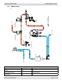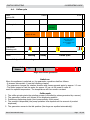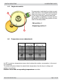
1
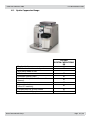
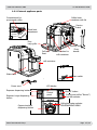
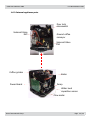
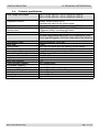
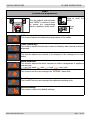
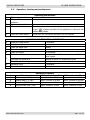
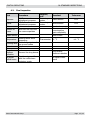
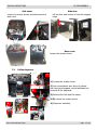
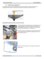
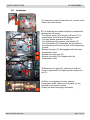
HD8838
Coffee Machine
Syntia cappuccino
Service
Service Manual
Contents
Page
Contents
Page
1.
Introduction
4.9.
Auto-learning dose (SAS)
6
1.1.
Documentation required
1
4.10.
Water level detection (water tank)
7
1.2.
Tools and equipment required
1
4.11.
Water level detection (drip tray)
7
1.3.
Material
1
4.12.
Descaling request
8
1.4.
Safety warnings
1
4.13.
Anti-scale filter
8
1.5.
Syntia Cappuccino Range
2
1.6.1.
External appliance parts
3
5.
Troubleshooting
1.6.2.
Internal appliance parts
4
5.1.
Test mode
1
5.2.
Error messages
6
2.
Technical specifications
2.1.
Technical specifications
1
6.
Standard inspections
2.2.
Appliance parameters and performance
2
6.1.
Repair schedule
1
6.2.
Service schedule
1
6.3.
Final inspection
2
7.
Disassembly
7.1.
Outer elements
1
7.2.
Coffee dispenser
2
7.3.
Coffee grinder adjustment
3
7.4.
Keyboard card and control knob
4
7.5.
Power/CPU Board
4
7.6.
Gearmotor
5
7.7.
Boiler
6
7.8.
Stopcock
6
7.9.
Pump and flow meter
7
7.10.
Solenoid valves
7
3.
User instructions
3.1.
Customer and programming menu
1
3.2.
Operation, cleaning and maintenance
5
4.
Operating logic
4.1.
Water circuit
1
4.2.
Frother valve assembly
2
4.3.
Stopcock
2
4.4.
Coffee cycle
3
4.5.
Single microswitch
4
4.6
Temperature sensor
4
4.7.
Coffee grinder
5
4.8.
No-bean detection, dose adjustment, blocked coffee
grinder
5
All parts of this document are the property of Saeco International Group.
All rights reserved. This document and all the information herein is provided without liability deriving from any
errors or omissions. Furthermore, no part may be reproduced, used or collected with the exception of that
authorised in writing or in accordance with a contractual agreement.
Published by Saeco International Group Subject to modification
©
Copyright
EN 4219 400 00008
2010-November-rev.00
Contents
Page
7.11.
Coffee grinder
8
7.12.
Adjusting/removing and installing the grinder blades
8
7.13.
Installing and removing Oetiker clamps
9
8.
Notes
9.
Water circuit diagram
10.
Electrical diagram
Saeco International Group
SYNTIA CAPPUCCINO
Saeco International Group
SYNTIA CAPPUCCINO
SYNTIA CAPPUCCINO
01 INTRODUCTION
1.1. Documentation required
The following documentation is required for repairs:
• Instruction booklet of the specific model
• Technical documentation of the specific model (diagrams, exploded drawings)
1.2. Tools and equipment required
Besides standard equipment, the following tools are required:
Qty.
1
1
1
1
1
Description
Screwdriver
Pliers for Oetiker clamps
AC - DC - Vdc tester
Digital thermometer
SSC (Saeco Service Center)
Notes
Torx T 8 - T 10 - T 20
Full scale > 150°C
Programmer
(for programming and diagnosis mode)
1.3. Material
Description
Thermal grease
Descaler
Degreaser
Silicone grease
Notes
Thermal resistance > 200°C
Saeco descaler
Personal choice
Safe to use with food
1.4. Safety warnings
It is recommended to consult the technical manual of the appliance before implementing any
operation.
Comply with all applicable standards relating to the repair of household appliances.
Always disconnect the power plug from the mains before beginning repairs on the appliance.
Simply turning off the main switch is not sufficiently safe to prevent electrical discharges.
This household appliance is rated as insulation class I.
On completion of the repairs, insulation and dielectric rigidity tests must be performed.
Saeco International Group
Page 01 / 04
SYNTIA CAPPUCCINO 01 INTRODUCTION
1.5. Syntia Cappuccino Range
Display interface
With brushed stainless steel parts
With parts made of ABS
Milk carafe
Automatic dosing (SAS)
Quantity of dispensed coffee saved in
memory
Auto-rinse
Automatic shutdown
(after 60' inactivity)
Compartment for ground coffee
Automatic descaling cycle
Saeco International Group
DO PSA
SYNTIA CAPPUCCINO
SS
X
X
X
X
X
X
X
X
X
Page 02 / 04
SYNTIA CAPPUCCINO
01 INTRODUCTION
1.6.1.External appliance parts
Compartment for
pre-ground coffee
Coffee bean
container with lid
Service
hatch
Grind level
adjustment
Drip
tray+grille
Brewing unit
Full tank
float
Connection for
milk container
Dreg
drawer
milk container
Water tank
Main switch
Power cord
Expresso dispensing button
Expresso lungo dispensing
button
Cappuccino/milk
dispensing button
Saeco International Group
LCD display
Control
panel
ON/OFF button
Pre-ground coffee “flavour”/
hot milk selector
Coffee/hot water selector
PROGRAMMING MENU
Page 03 / 04
SYNTIA CAPPUCCINO 01 INTRODUCTION
1.6.2.Internal appliance parts
Door lock
microswitch
Solenoid Valve
EV2
Ground coffee
conveyor
Solenoid Valve
EV1
Coffee grinder
Power Board
Boiler
Pump
Water level
capacitive sensor
Flow meter
Saeco International Group
Page 04 / 04
Saeco International Group
SYNTIA CAPPUCCINO
SYNTIA CAPPUCCINO
02 TECHNICAL SPECIFICATIONS
2.1. Technical specifications
Power supply and output:
240 V~ 50 Hz 1400 W - 230 V~ 50/60 Hz 1400 W 120 V~ 60 Hz 1500 W - 100 V~ 50/60 Hz 1300 W
Temperature control:
Variable resistor sensor (NTC)
transmits the value to the control board
2 manual reset or one-shot thermostats (175°C)
(230/120 V~) 1300 W – (100 V~) 1100 W
to dispense coffee, hot water and steam
33VC 2 rotation directions; 24VC power supply
Safety system:
Coffee heat exchanger output:
Stainless steel
Gearmotor:
Pump:
Overpressure valve:
Water filter:
Coffee grinder:
Automatic dosage
Consumption:
Consumption in Stand-by
Dimensions: W x H x D in mm:
Weight:
Water tank capacity:
Coffee container capacity
Dreg drawer capacity
Heat exchanger capacity:
Water circuit filling time:
Heating time:
Dispensing temperature:
Grinding time:
Saeco International Group
Ulka with reciprocating piston and 120°C cutout 48 W, 230V,
50 Hz, Type EP5 approx. 13-15 bar 120V, 60Hz 100V, 50/60 Hz
Opening at approx. 16-18 bar
In tank
Direct current motor with flat ceramic grinder blades
Dose adjustment controlled by the electronic system
During the heating phase - approx. 5.6 A
<1W
256x315x415
9 kg
1.2 l.
260 g coffee beans
8
Approx. 10 cc
Approx. 15 sec Max. on first filling cycle
Approx. 45 sec.
Approx. 84°± 4°
approx. 8-10 sec.
Page 01 / 03
SYNTIA CAPPUCCINO
02 TECHNICAL SPECIFICATIONS
2.2. Appliance parameters and performance
PRODUCT
QUANTITY
Expresso
Average coffee
Expresso lungo
Pre-ground
Hot water
Steam
Minimum
quantity
(Puls.)
70
No
70
Default
quantity
(Puls.)
165
No
440
Maximum
quantity
(Puls.)
600
No
600
Set
Set by the
by the
Production/Service Dept
user
Yes
No
No
No
Yes
No
Yes
Continues until the water is used up (capacitive sensor)
Continues until the water is used up (capacitive sensor)
RINSE
When performed
Initial rinse
When the appliance is switched
on and the boiler temperature is
≤ 50°C
No. of Pulses
Stop option
Can be disabled by the user
Can be disabled by the
Production/Service Dept
No. of pulses adjustable by
the user
No. of pulses adjustable by
the Production/Service Dept
Pulse range
(Min - Max)
180
Yes, by pressing any button
No
Final rinse
When the machine is switched
off electronically, manually or
automatically after 60', if at least
one coffee has been dispensed
before being switched off
80
Yes, by pressing any button
No
No
No
No
No
No
No
No
No
WATER HARDNESS
ADJUSTABLE
Descaling frequency
Hardness
Water hardness
Without anti-scale filter
With anti-scale filter
1
Soft (up to 7°dH)
240 litres (480,000 pulses)
480 litres (960,000 pulses)
2
Medium (7° - 14°dH)
120 litres (240,000 pulses)
240 litres (480,000 pulses)
3
Hard (15° - 21°dH)
60 litres (120,000 pulses)
120 litres (240,000 pulses)
4
Very hard (over 21°dH)
30 litres (60,000 pulses)
60 litres (120,000 pulses)
The default water hardness level is 3. Each litre of water corresponds to approximately 2,000
pulses.
Saeco International Group
Page 02 / 03
SYNTIA CAPPUCCINO
02 TECHNICAL SPECIFICATIONS
DREG DRAWER
Time-out for dreg drawer
Alarm to empty dreg drawer block after
Description and values
5 sec.
8 lots of dregs
(double expresso as the last dispensed product)
Warning to empty dreg drawer
Reset dreg counter
(9 lots of dregs)
No
Each time the dreg drawer is removed for at
least 5 seconds, even if the "empty dreg drawer"
alarm is not triggered
STAND-BY
Input time (min - max)
Input time (default)
Input time set by user
Input time set by
the Production/Service Dept
Boiler temperature during Stand-by
WATER TANK
Level sensor
Water reserve (pulses)
Water reserve modifiable by
the Production/Service Dept
"Fill tank" alarm
"No tray" alarm
Water mains
Saeco International Group
Description and values
15 minutes - 180 minutes
60 minutes
Yes
Yes
Boiler OFF
Description
Yes
200
No
Yes
No
No
Page 03 / 03
Saeco International Group
SYNTIA CAPPUCCINO
SYNTIA CAPPUCCINO
03 USER INSTRUCTIONS
3.1. Customer and programming menu
Expresso dispensing button
Expresso lungo dispensing
button
LCD display
Cappuccino/milk
dispensing button
ON/OFF button
Pre-ground coffee “flavour”/
hot milk selector
Coffee/hot water selector
PROGRAMMING MENU
Appliance ready mode indications (GREEN)
Indications
Causes
The appliance has reached the temperature
- to dispense coffee beans
- to dispense hot water
The appliance has reached the temperature
- to dispense ground coffee
(pre-ground)
Dispense the product
The appliance is ready to dispense hot milk
Dispense the product
The appliance is dispensing hot water
Dispense hot water
The appliance is dispensing a coffee
Wait for the dispensing process to end (press
the button again to stop dispensing)
The appliance is dispensing two coffees
Wait for the dispensing process to end (press
the button again to stop dispensing)
MEMO
Solutions
Dispense the product
The appliance is dispensing a cappuccino with
Stop the dispensing process as desired
coffee beans.
The appliance is dispensing a cappuccino with
Stop the dispensing process as desired
ground coffee.
M
E
M
O
The appliance is programming the amount of
Stop the dispensing process as desired
coffee to be dispensed.
M
E
M
O
The appliance is programming the amount of
Stop the dispensing process as desired
hot milk to be dispensed.
M
E
M
O
The appliance is programming the amount of
Stop the dispensing process as desired
cappuccino to be dispensed.
Saeco International Group
Page 01 / 05
SYNTIA CAPPUCCINO
Warning indications (ORANGE)
Indications
Causes
03 USER INSTRUCTIONS
Solutions
Appliance is in heating mode to Wait for the heating process to end
dispense coffee, hot water or steam (see the progress bar)
The appliance is in rinsing mode
wait for the appliance to complete the Wait for the operation to be completed
operation
Perform a descaling cycle
The machine requires a
Press the aroma/pre-ground coffee
button for 5 seconds to access the
descaling cycle
descaling cycle
The brewing unit is in restart mode
for the appliance to be reset
Wait for the restart to be complete
MENU
Fill the coffee bean container and
restart the dispensing cycle
Fill the coffee bean container
Replace the filter. This message is
The appliance requires the Intenza
displayed if the function is activated
filter to be replaced
via the programme
+
-
ESC
ON
OFF
RESET
The alarm is only disabled if “RESET” is
performed via the programme
OK
CLEAN
OK
The appliance requires the milk After having washed the milk unit, press the
system to be cleaned
button to cancel the message
Alarm indications (RED)
Indications
Causes
Solutions
Switch the appliance off and back on after 30 If the appliance does not go on, contact the
Service Centre.
1 seconds. Repeat this twice or three times
START
Problems with the water circuit. Press the
button to start the manual loading Wait for the circuit to fill up
cycle of the water circuit
No coffee beans inside the container.
Restart the cycle after having filled the
coffee container
No water
Fill the water tank
Saeco International Group
Page 02 / 05
SYNTIA CAPPUCCINO
03 USER INSTRUCTIONS
Indications
Causes
Solutions
Service hatch open: Close it
If the service hatch is opened while a product is being dispensed, the appliance
stops dispensing and starts a 30 sec countdown before cancelling the dispensing
30
process. The countdown can be interrupted by closing the service hatch and the
dispensing process continues where it stopped from.
Bring the hot water/steam stopcock knob to the correct position.
If the knob is turned (opened) while a product is being dispensed, the appliance
stops dispensing and starts a 30 sec countdown before cancelling the dispensing
30 process. The countdown can be interrupted by closing the knob and the dispensing
process continues where it stopped from.
No brewing unit
If the brewing unit is removed while a product is being dispensed, the appliance
stops dispensing and starts a 30 sec countdown before cancelling the dispensing
30 process. The countdown can be interrupted by reinserting the brewing unit and
closing the door - the dispensing process continues where it stopped from.
To reset the dreg counter, wait for the
Empty the dreg drawer and the drip tray dreg value inside the icon on the display
to disappear (5 seconds)
Insert the dreg drawer
Indications
OK
S a e co
ESC
STOP
START
STOP
Causes
When the dreg counter is reset, the icon
is displayed with no dreg value
Solutions
Descaling CYCLE
(press the Aroma/pre-ground coffee button for 5 seconds)
START
1) Initial screen to enter the
5) Rinse cycle of the descaling
descaling cycle.
cycle during the pause mode
Press "esc" to exit
6) Descaling cycle ended.
2) Descaling cycle being
Press the
button to exit the
END
performed
cycle
7) Fill the tank with fresh
3) Descaling cycle in Pause mode
water
4) Rinse cycle of the descaling
cycle being performed
Saeco International Group
Page 03 / 05
SYNTIA CAPPUCCINO
03 USER INSTRUCTIONS
MENU
(controls and programmes)
Turn the selector anti-clockwise
until "MENU" is reached in order
to access the programming
menu in appliance ready mode
+
MAX
MED
MIN
ESC
Press to scroll the
MENU
Press
edit
Coffee temperature:
This function adjusts the dispensing temperature of the coffee.
+
-
180’
60’
30’
15’
+
ESC
ESC
Timer (Stand-by):
This function adjusts the interval to switch to Stand-by after the last product is
dispensed.
Contrast:
This function adjusts the contrast of the display for the messages to be read
better.
+
ESC
+
ESC
ON
OFF
RESET
Water hardness:
This function adjusts the water hardness for better management of appliance
maintenance.
= very soft water
=soft
=hard
=very hard
"INTENZA" water filter
This function lets the user manage the "INTENZA" water filter.
-
Descaling cycle
This function lets the user manage the appliance descaling cycle.
START
+
ESC
YES
Default settings
This function restores the default settings.
NO
-
Saeco International Group
Page 04 / 05
SYNTIA CAPPUCCINO
03 USER INSTRUCTIONS
3.2. Operation, cleaning and maintenance
Operating the machine
1
2
3
4
5
A
B
C
D
E
F
H
G
Fill the water tank
Fill the coffee bean
container
Switch on the appliance
Fill the circuit
Insert a container beneath the dispenser, turn the selector
Press the coffee button
to the ”
“ symbol and wait for the appliance to return to the
coffee ready mode.
Press once for one coffee and twice for two coffees
CLEANING AND TECHNICAL ASSISTANCE
Empty the dreg drawer
If indicated
Empty the drip tray
As necessary
Clean the water tank
Weekly
Clean the coffee bean container
As necessary
Clean the casing
As necessary
Clean the coffee unit
Every time the coffee bean container is filled or
once a week
Lubricate the coffee unit
Monthly or after 500 dispensing cycles
Clean the unit housing
Weekly
Descaling cycle
If indicated
Clean the milk frother
After it is used
Descaling frequency
Hardness
Water hardness
Without anti-scale filter
1
Soft water (up to 7°dH)
Approx. 3 months or 120 litres
2
Medium Water (7°-14°dH)
Approx. 2 months or 90 litres
3
Hard Water (15°-21°dH)
Approx. 6 weeks or 60 litres
4
Very hard water (over 21°dH)
Approx. 4 weeks or 30 litres
Saeco International Group
With anti-scale filter
Approx. 6 months or 240 litres
Approx. 4 months or 180 litres
Approx. 3 months or 120 litres
Approx. 6 weeks or 60 litres
Page 05 / 05
Saeco International Group
SYNTIA CAPPUCCINO
SYNTIA CAPPUCCINO
04 OPERATING LOGIC
- COLD WATER
- HOT WATER/STEAM
COFFEE
DISPENSER
UNIT
BOILER
FROTHED MILK/HOT WATER
FROTHER
MILK CARAFE
3-WAY SOLENOID VALVE
EV2
WATER DRAIN
2-WAY SOLENOID VALVE
DRAIN
EV1
4.1. Water circuit
WATER
TANK
PUMP
FLOW METER
STATUS OF SOLENOID VALVES EV1 AND EV2 DURING THE VARIOUS FUNCTIONS
FUNCTION
EV1
EV2
COFFEE
OFF
OFF
FROTH/CAPPUCCINO
ON
ON (it opens after 5 seconds to drain any water residue
inside the circuit)
HOT WATER
ON
ON
Saeco International Group
Page 01 / 08
SYNTIA CAPPUCCINO
04 OPERATING LOGIC
4.2. Frother valve assembly
STEAM
VENTURI
PIPE
1
CARAFE
CONNECTION
3
CARAFE
2
MILK
AIR
AIR
CHANNEL
MILK
FROTHED
MILK
The milk is frothed as follows:
1)The steam goes through the frothing valve, thereby creating a depression that draws the milk
and a percentage of air
2)The milk is drawn from the carafe and is mixed with the air that is drawn through the slot on
the carafe connection.
3)STEAM - AIR - MILK are mixed inside the Venturi Pipe, thereby forming froth.
4.3. Stopcock
5
1
2
3
4
No.
1
2
3
4
5
DESCRIPTION
Mushroom valve cap
Spring for the mushroom valve
Mushroom valve support
Mushroom valve
O-ring seal
When dispensing coffee - cappuccino, the mushroom valve opens at 4bar +/- 0.5.
Saeco International Group
Page 02 / 08
SYNTIA CAPPUCCINO
04 OPERATING LOGIC
4.4. Coffee cycle
Main
switch ON
START
STOP
Time
Coffee grinder
Pulses
(Dosage)
Heating
approx.45 sec.
Pump
*
Pump action
(flow meter pulses)
depending on
the set quantity of the
product
Gearmotor
Brewing unit
Heating
Mode
Ready
Coffee cycle
Notes: * Only with Pre-brewing
Microswitch
Status
OFF
ON
Single microswitch gearmotor
Switch-on
When the appliance is switched on, the gearmotor repositions itself as follows:
- It stresses microswitch 1 (see the following chapter)
- The gearmotor changes the rotation direction and moves upwards again by approx. 1-2 mm
- The boiler begins to heat the water for approx. 45 sec. at full power in order to
reach the optimal temperature. The temperature will then remain constant.
Coffee cycle
The coffee grinder starts the grinding process (controlled by pulses generated by a sensor)
The gearmotor (coffee unit) moves to the dispensing position
Preliminary dispensing phase (short pump activity, short pause)
The product is dispensed (the pump operation time depends on the amount of product
dispensed)
5. The gearmotor moves to the idle position (the dregs are expelled automatically)
1.
2.
3.
4.
Saeco International Group
Page 03 / 08
SYNTIA CAPPUCCINO
04 OPERATING LOGIC
4.5. Single microswitch
The gearmotor is activated by a direct current
motor that acts on the smaller double toothed
wheel via a worm screw. The unit is mounted
on the axle of the large toothed wheel and
when a coffee is requested, it moves from the
idle position to the dispensing position to then
return to the idle position.
2
- Idle position: 1
- Dispensing position: 2
1
4.6. Temperature sensor (adjustment)
Temp. (° C) R nom (kΩ)
20
61.465
50
17.599
75
7.214
80
6.121
85
5.213
90
4.459
100
3.3
125
1.653
150
0.893
ΔR (+/- %)
8.6
5.9
4.1
3.7
3.4
3.1
2.5
3.9
5.1
An NTC is used as a temperature sensor, which reduces the resistors consumption, in the event
of overheating.
The electronic system detects the actual boiler temperature from the drop in voltage and
adjusts it accordingly.
Resistor values and corresponding temperatures: see table
Saeco International Group
Page 04 / 08
SYNTIA CAPPUCCINO
04 OPERATING LOGIC
4.7. Coffee grinder
5
6
4
1
2
3
The coffee grinder is activated by a direct current motor (1) via helicoidal wheel transmission and
a worm screw (2).
The worm screw (2) activates a plastic toothed wheel (3), which turns the lower grinder blade (4)
and the increment pin (5)
There are two magnets (6) in the toothed wheel and with every rotation they transmit two pulses
to a Hall sensor, which in turn transmits them to the electronic system.
V
4.8.
Detection of coffee bean absence, dose adjustment,
blocked coffee grinder
Without beans n=100%
t1
With beans n=100%
t2
No coffee
When no coffee beans are present, this is detected by the Hall
sensor due to variations in the pulse frequency (with or without
coffee).
If there are no coffee beans (operation while empty), the number
of rotations and therefore the number of pulses, will be greater.
t1 = no coffee indication
If there are coffee beans, the number of rotations will be lower
due to the force created during the grinding process.
t2 = no indication
Without beans n=50%
t3
t4
Saeco International Group
t3 and t4 = this reading is taken at the end of each grinding
process
Dose quantity adjustment
The dose quantity is adjusted in accordance with the pulses
detected.
With beans n=50% (number of rotations proportional to the weak, medium and
strong flavour selection).
Blocked grinder blades
If the coffee grinder is blocked for any reason, pulses will no
longer be transmitted to the electronic system and the grinder
stops.
t
Page 05 / 08
SYNTIA CAPPUCCINO
4.9
04 OPERATING LOGIC
Auto-learning dose (SAS)
The aim of this function is to automatically adjust the average dose of ground coffee (AUTOLEARNING); this occurs by means of an algorithm based on three pieces of information detected
by the appliance board:
1. Number of coffee grinder pulses during the grinding cycle
2. Max average value of the power consumed by the gearmotor during the coffee brewing cycle
3. Flavour selected by the user
The algorithm compares the maximum average value of the power consumed by the gearmotor
with the value shown in the table, depending on the selected flavour, in order to calculate the new
grinding pulse value for the next coffee product.
If the consumption value is less than the minimum current value, the grinding pulses will be
increased by 2.
If the consumption value is greater than the maximum current value, the grinding pulses will be
decreased by 4.
If the consumption value falls within the "excessive stress" range, the product is dispensed and
the grinding pulses will be decreased by 10.
If the consumption value falls within the "expel" range, the pad will be expelled and the grinding
pulses decreased by 10.
If the "pre-ground" flavour is selected by the user, no modification is made.
This guarantees that regardless of the coffee type used, the grinding adjustment
and any wear on the grinder blades always remains constant.
Setting / Status
Power consumption
in mA
The pulse is corrected in the next grinding process
Exceeded in excess
Exceeded in default
A
Mild flavour
200 - 300 mA
-4
+2
B
Medium Flavour
301 - 450 mA
-4
+2
C
Strong Flavour
451 - 600 mA
-4
+2
D
Stress
601 - 800 mA
-4
E
Excessive stress
801 - 1,000 mA
- 10
F
Pad expulsion
> 1000 mA
- 10
Important:
For perfect operation, the adjustment is carried out in the area of the fields highlighted in
green (A, B and C). When the type or brand of coffee is changed, there may be variations
in the size of the beans and their stickiness or roasting level. This leads to variations in
power consumption (mA), resulting in excessive or insufficient doses (until the adjustment
compensates this change).
Caution: In case of an excessive dose, ground coffee can fall into the dreg drawer.
This is not a fault, but can occur when the machine is switched on or following a
service.
Saeco International Group
Page 06 / 08
SYNTIA CAPPUCCINO
04 OPERATING LOGIC
4.10. Water level detection (water tank)
Water absence indication (water reserve)
Water tank
Sensor
200 puls.
Function:
The water level is monitored by a capacitive sensor, located one
third up the water tank wall.
If the electronic system detects that the water is below the relative
level by means of the sensor, a water reserve of 200 pulses of the
flow meter remains available for the dispensing process.
The product dispensing process is then completed.
If a dispensing process ends after the sensor has intervened (in the
reserve), the "water absence" indication continues to be displayed
as from the next dispensing process
4.11. Water level detection (drip tray)
Empty residual water tank indication
Residual water tank
Sensor
Total
capacity
Level of
sensor
intervention
Saeco International Group
Function:
The residual water level is monitored by a capacitive
sensor. The sensor is located approximately half way up
the upper edge of the residual drip tray. To make the best
of the tray capacity, the sensor is positioned near a dam
device. In this way, the residual water tray fills up to the
upper edge and overflows inside and when it reaches
the sensor, it triggers the "empty residual water tank"
indication.
Page 07 / 08
SYNTIA CAPPUCCINO
04 OPERATING LOGIC
4.12. Descaling request
Flow meter pulses
Descaling indication with anti-scale filter
(only in appliances equipped with a display)
The water hardness is set on the basis of the
regional water hardness analysis (1, 2, 3, 4).
Enabled
filter
Disabled filter:
If the function is disabled, the electronic system
counts the flow meter pulses, recording one pulse
for every revolution.
Disabled
filter
Enabled filter:
If the function is enabled, the electronic system
counts the flow meter pulses, recording one pulse
for every two revolutions.
Number of pulses
360°
1 rev
"Change anti-scale filter" indication
The electronic system uses the flow meter pulses
to keep track of the amount of water that flows
and once the defined litres are exceeded (based
on the water hardness setting), the "Replace filter"
indication is triggered.
4.14 Anti-scale filter
Anti-scale filter
Function:
• Reduced limescale deposits that take longer to form.
• Improved water quality.
• Better taste due to ideal water hardness.
Descaling duration / efficiency:
• - 10° dH
• 60 litres
• 2 months
Bypass
Saeco International Group
To obtain a linear characteristic of its effectiveness,
throughout the duration of the descaling process, the
water is split according to the degree of hardness in a
three-phase by-pass (A,B and C).
See small picture.
Page 08 / 08
Saeco International Group
SYNTIA CAPPUCCINO
SYNTIA CAPPUCCINO
05 TROUBLESHOOTING
5.1. Test mode
To enter Test Mode:
1. place the control knob in the water position
2. keep the expresso button pressed
3. switch the appliance on from the 0/I button at
the back
4. release the expresso button
lev.
knob
pos.
display
button
Software
version
L0
FIRMWARE
00.02.00
function
notes
The software
version is
displayed
The software version must be the
same as that on the label of the
Microprocessor.
PRESS THE ON/OFF BUTTON TO ACCESS THE UPPER LEVEL
L1
KEYBOARD
Functional verification of the buttons
1N
2N
N
3
N5
N4
KEYBOARD
1Y
2N
N
3
N5
N4
KEYBOARD
1N
2Y
N
3
N5
N4
KEYBOARD
1N
2N
Y
3
N5
N4
KEYBOARD
1N
2Y
N
3
N5
Y4
KEYBOARD
1Y
2N
N
3
Y5
N4
PRESS THE
Saeco International Group
Initial status, buttons not pressed
the no. 1 from
“N to Y” and the If the display does not change with
display changes respect to the initial status, replace
from green to red the interface board and/or the
JP21 flat cable. If the colour of the
the no. 2 from “N to display remains green, check the
Y” and the display JP4 wiring from the interface board
changes from green to the display.
to orange
the no. 3 from
If the display does not change with
“N to Y” and the respect to the initial status, replace
display remains the interface board and/or the JP21
green
flat cable.
the no. 4 from
“N to Y” and the If the display does not change with
display remains respect to the initial status, replace
the interface board and/or the
green
JP21 flat cable. If the colour of the
the no. 5 from
display remains green, check the
“N to Y” and the JP4 wiring from the interface board
display remains to the display.
green
ON/OFF BUTTON TO ACCESS THE UPPER LEVEL
01
Page
/ 06
SYNTIA CAPPUCCINO
lev.
knob
pos.
display
05 TROUBLESHOOTING
button
INPUTS
L2
TAPMENU=N DOOR=Y
TAPCAP= Y BU-P=Y
TAPWATER=N DREG=Y
TANK-H2O=Y TRAY=Y
INPUTS
TAPMENU=N DOOR=Y
TAPCAP= Y BU-P=Y
TAPWATER=N DREG=Y
TANK-H2O=N TRAY=Y
INPUTS
Functional verification
microswitches and sensors
TAPMENU=N DOOR=N
TAPCAP= Y BU-P=Y
TAPWATER=N DREG=N
TANK-H2O=Y TRAY=Y
INPUTS
TAPMENU=N DOOR=N
TAPCAP= Y BU-P=Y
TAPWATER=N DREG=Y
TANK-H2O=Y TRAY=Y
INPUTS
TAPMENU=N DOOR=Y
TAPCAP= Y BU-P=N
TAPWATER=N DREG=Y
TANK-H2O=N TRAY=Y
INPUTS
TAPMENU=N DOOR=Y
TAPCAP= Y BU-P=Y
TAPWATER=N DREG=Y
TANK-H2O=Y TRAY=N
INPUTS
TAPMENU=N DOOR=Y
TAPCAP= N BU-P=Y
TAPWATER=Y DREG=Y
TANK-H2O=Y TRAY=Y
INPUTS
TAPMENU=N DOOR=Y
TAPCAP= Y BU-P=Y
TAPWATER=N DREG=Y
TANK-H2O=Y TRAY=Y
INPUTS
MENU
MENU
TAPMENU=Y DOOR=Y
TAPCAP= N BU-P=Y
TAPWATER=N DREG=Y
TANK-H2O=Y TRAY=Y
Remove
the
water
tank
Remove
the dreg
drawer
Open
the side
door
Remove
the
brewing
unit
Remove
the drip
tray
function
notes
Initial status:
Unit connected, dreg drawer inserted, water tank full,
water drip tray inserted, side door closed and control
knob in the coffee position.
TANK-H2O
If the TANK-H2O signal does not
signal changes
change, check the capacitive sensor
from “Y” to
and the JP23 wiring.
"N"
The DREG
If the signal does not change, check
signal changes
the dreg drawer microswitch and the
from “Y” to
JP16 wiring.
"N"
The DOOR
If the DOOR signal does not change,
signal changes
check the microswitch of the door and
from “Y” to
the JP16.
"N"
The BU-P
If the BU-P signal does not change,
signal changes
check the unit presence microswitch
from “Y” to
and the JP14.
"N"
The TRAY
If the BU-P signal does not change,
signal changes
check the unit presence microswitch
from “Y” to
and the JP14.
"N"
Knob in
water
pos.
TAP-WATER
signal from
“N” to "Y"
Knob in
coffee
pos.
TAP-COFFE
signal
from “N” to
"Y"
Knob in
MENU
pos.
TAP-MENU
signal from
“N” to "Y"
If the
TAPWATER, TAPCOFFE, TAPMENU
indication does not change, check the
knob board and/or the connection
wiring with interface board JP2.
PRESS THE ON/OFF BUTTON TO ACCESS THE UPPER LEVEL
Saeco International Group
Page 02 / 06
SYNTIA CAPPUCCINO
lev.
L3
knob
pos.
display
button
function
notes
BU PAGE
WORK=Y
HOME=N
Functional verification
Brewing unit
05 TROUBLESHOOTING
CUR= 0
Initial status, buttons not pressed
CUR= --- corresponds to the motor
consumption of the gearmotor and
BU PAGE
Bring the
this value must be:
unit to the
WORK=Y
WITH THE UNIT DISCONNECTED
HOME=N CUR= 178
"WORK"
less than 200mA
position
WITH THE UNIT CONNECTED
less than 300 mA
BU PAGE
ERROR: WORK signal remains “N” and the display colour
changes from green to red. Check the gear microswitch
WORK=N
HOME=N CUR= 497
in the gearmotor (broken or inserted wrongly) and the
motor (blocked). Check the JP16 wiring.
ERROR:(WITH THE UNIT DISCONNECTED) The
BU PAGE
current consumption of the gearmotor is greater than
WORK=N
HOME=N CUR= 203
200mA, the display colour changes from green to red,
check the unit and/or the gearmotor.
BU PAGE
ERROR:(WITH THE UNIT CONNECTED) If the current
WORK=N
consumption of the gearmotor is greater than 300mA,
HOME=N CUR= 337
the display colour changes from green to red, check
the unit and/or the gearmotor.
CUR= --- corresponds to the motor
consumption of the gearmotor and
BU PAGE
Bring the unit this value must be:
WORK=N
to the "HOME" WITH THE UNIT DISCONNECTED
HOME=Y CUR= 193
less than 200mA
position
WITH THE UNIT CONNECTED
less than 300 mA
ERROR: HOME signal remains “N” and the display
BU PAGE
colour changes from green to red. Check the
WORK=N
HOME=N CUR= 497
microswitch of the gearmotor (broken or inserted
wrongly) and the motor (blocked), the JP16 wiring.
ERROR:(WITH THE UNIT DISCONNECTED) The
BU PAGE
current consumption of the gearmotor is greater than
WORK=N
HOME=N CUR= 203
200mA, the display colour changes from green to red,
check the unit and/or the gearmotor.
BU PAGE
ERROR:(WITH THE UNIT CONNECTED) The current
consumption of the gearmotor is greater than 300mA,
WORK=N
HOME=N CUR= 337
the display colour changes from green to red, check
the unit and/or the gearmotor.
PRESS THE ON/OFF BUTTON TO ACCESS THE UPPER LEVEL
Saeco International Group
Page 03 / 06
SYNTIA CAPPUCCINO
lev.
L4
knob
pos.
05 TROUBLESHOOTING
display
EV
function
notes
PUMP
EV1 OFF IMP=0
EV2 OFF L/H= 0
Initial status, buttons not pressed
and stopcock in water position.
Press the flavour button for the water to pass through
the boiler pin and the pulse indicator (PULS) will
EV1 OFF IMP=142
increase, whereas the litre/hour (L/H) indicator should
EV2 OFF L/H= 1 5
be between 14 and 18.
ERROR: The display colour changes from green to
red and the pulses remain at 0, check the pump, flow
EV
PUMP
meter, its wiring and/or the connection on the POWER/
EV1 OFF IMP=0
CPU board (JP5), the wiring of the pump and/or the
EV2 OFF L/H= 0
connection on the POWER/CPU board (JP24). If the
water does not pass through the boiler pin but through
the milk circuit or the safety/drain valve, verify the
operation of solenoid valve EV1 or EV2.
EV
PUMP
Press the expresso button to activate the solenoid valve
EV1 and activate the pump (flavour button) for the
EV1 ON IMP=238
water to come out of the safety/drain valve. The litre/
EV2 OFF L/H= 1 5
hour (L/H) indicator should be between 14 and 18.
ERROR: The display colour changes from green to
red and the pulses remain at 0, check the pump, flow
EV
PUMP
meter, its wiring and/or the connection on the POWER/
EV1 ON IMP=0
CPU board (JP5), the wiring of the pump and/or the
EV2 OFF L/H= 0
connection on the POWER/CPU board (JP24). If the
water does not pass through the safety/drain valve
but through the milk circuit or the boiler pin, verify the
operation of solenoid valve EV1 or EV2.
Press the expresso button to activate the solenoid
EV
PUMP
valve EV1 and activate the pump (flavour button) for
EV1 ON IMP=238
the water to come out of the milk circuit. The litre/
EV2 ON L/H= 1 5
hour (L/H) indicator should be between 14 and 18.
ERROR: The display colour changes from green to
red and the pulses remain at 0, check the pump,
EV
PUMP
flow meter, its wiring and/or the connection on the
POWER/CPU board (JP5), the wiring of the pump and/
EV1 ON IMP=0
or the connection on the POWER/CPU board (JP24).
EV2 OFF L/H= 0
If the water does not pass through the milk circuit but
through the safety/drain valve or the boiler pin, verify
the operation of solenoid valve EV1 or EV2.
PRESS THE ON/OFF BUTTON TO ACCESS THE UPPER LEVEL
EV
Functional verification Pump /
Solenoid Valves EV1 - EV2
button
Saeco International Group
PUMP
Page 04 / 06
SYNTIA CAPPUCCINO
lev.
L5
knob
pos.
05 TROUBLESHOOTING
display
function
notes
HEATER GRINDER
OFF
30
0
0
15
HEATER GRINDER
OFF
30
40
15
14
HEATER GRINDER
OFF
30
Functional verification
coffee grinder - boiler
button
0
0
15
HEATER GRINDER
ON
49
40
15
14
HEATER GRINDER
OFF
159
SHORT
40
15
14
HEATER GRINDER
OFF
71
OPEN
40
15
14
Initial status, buttons not pressed.
The number that indicates the rotation of the COFFEE
GRINDER MOTOR increases up to 40. The other two numbers
shown on the display are not important for the test mode.
ERROR: The number remains 0 and the motor of the coffee
grinder does not rotate, the display colour changes from green
to red, check the sensor and/or the coffee grinder motor, the
wiring of the sensor and/or the connection on the POWER/
CPU board (JP2), the wiring of the coffee grinder motor and/
or the connection on the POWER/CPU board (JP8).
The current consumption is OK, the HEATER signal
changes from “OFF” to “ON” and the temperature
value increases.
ERROR: "SHORT" appears in the HEATER signal,
the temperature sensor of the boiler is interrupted,
the colour of the display changes from green to red,
check the wiring of the boiler sensor and/or the
connection on the POWER/CPU board (JP13 could be
disconnected).
ERROR: "OPEN" appears in the HEATER signal, the
temperature sensor of the boiler is open, the colour
of the display changes from green to red, check the
wiring of the boiler sensor and/or the connection on
the POWER/CPU board (JP13 could be disconnected).
ERROR: The current consumption is NOT OK and the
temperature value does not increase, check the wiring
of the power supply and/or the connection on the
POWER/CPU board (JP17-3).
Saeco International Group
Page 05 / 06
SYNTIA CAPPUCCINO
05 TROUBLESHOOTING
5.2. Error messages
code
brief description
description
01
blocked coffee grinder
the coffee grinder is blocked (jammed grinder
blades or sensor is not reading properly)
03
brewing unit blocked in ‘work’
descent time-out exceeded
04
brewing unit blocked in ‘home’
ascent time-out exceeded
05
blocked water circuit
water does not flow in the flow meter
06
frother unit solenoid valve
short-circuit in a solenoid valve of the frother unit
10
coffee boiler short-circuit
coffee boiler temperature sensor short-circuit
11
coffee boiler in open circuit
coffee boiler temperature sensor in open circuit
12
steam boiler short-circuit
steam boiler temperature sensor short-circuit
13
steam boiler in open circuit
steam boiler temperature sensor in open circuit
14
various temperature errors
(in the coffee boiler)
coffee boiler temperatures out of control
15
various temperature errors
(in the steam boiler)
steam boiler temperatures out of control
16
coffee unit short-circuit
brewing unit microswitch short-circuit
17
not used
18
clock error
memory fault or impossible to set
19
no zero crossing
no zero crossing on board, could also be caused by
the power board
20
not used
Saeco International Group
Page 06 / 06
Saeco International Group
SYNTIA CAPPUCCINO
SYNTIA CAPPUCCINO
06 STANDARD INSPECTIONS
6.1. Repair schedule
1
2
3
4
5
6
7
8
9
10
11
12
13
14
15
16
17
18
Action
Visual inspection (damage during transport)
Appliance data check (plate)
Functional check / problem analysis
Opening the appliance
Visual inspection
Functional tests
Repairing the faults encountered
Checking any modifications (view info, new sw, etc.)
Service activities in accordance with the operating schedule
Internal cleaning
Functional test with the appliance open
Assembly
Final inspection test
Draining the circuit (in winter)
External cleaning
Lubricating the brewing unit with suitable grease
Insulation test HG 701 (dielectric)
Documentation
6.2. Service schedule
S
ES
D
CF
Replacement
Visual inspection
Descaling cycle
Functional check
Component
Water filter
Water tank lip seal
Boiler pin O-ring
Brewing unit
Pipes, fittings and Oetiker clamps
Coffee circuit pump
Hot water/steam circuit pump
Gearmotor
Coffee grinder
Water circuit
Frothing valve assembly
2-way solenoid valve
3-way solenoid valve
Saeco International Group
P
TR
R
Cleaning
Noise test
Adjustment
Action
P/S/CF
S/CF
S/CF
ES/P/CF
ES/CF
ES/TR/CF
ES/TR/CF
ES/TR/CF
P/R/CF
D/CF
ES/S/CF
ES/S/CF
ES/S/CF
Support/tool
Degreaser / Grease
Vacuum cleaner / brush
Saeco descaler
Page 01 / 02
SYNTIA CAPPUCCINO
06 STANDARD INSPECTIONS
6.3. Final inspection
Test
Expresso
Coffee
Noise
Amount of
cream
Procedure
2-3 Expressos for
adjustment purposes
2-3 Coffees for
adjustment purposes
Blow into the cup until
the cream separates
Cream colour
Support/
tool
Measuring
beaker
Measuring
beaker
Standard
Same amount
15%
Same amount
15%
Standard
The cream should
come together
again completely
Hazel brown
Reading taken while
Thermometer 84 ˚C
dispensing
Check the grain size of
Grinding level
the ground coffee
Hot water
Dispense water
Steam
Dispense steam
Dreg drawer
Dreg drawer
absence
Remove the dreg drawer
absence indication
indication
Start brewing a coffee
No signal coffee
No signal
with the coffee bean
beans
coffee beans
container empty
Temperature
Saeco International Group
Tolerance
± 4 ˚C
Page 02 / 02
Saeco International Group
SYNTIA CAPPUCCINO
SYNTIA CAPPUCCINO
07 DISASSEMBLY
7.1. Outer elements
Disassembly of the upper cover
1) Remove the dreg drawer,
water tank, coffee container
cover, water drip tray, brewing
unit, control knob cover and
the cappuccino button (use a
screwdriver as a lever).
2
2) Loosen the screws shown
and remove the finger protection
mushroom and the coffee
container.
1
4
3) Loosen the screws shown from
inside the compartments that
contain the water tank and dreg
drawer.
4) Move the upper cover
outwards to facilitate the removal
of the front panel.
3
5) Lift the upper cover and
disconnect the earth wire shown.
5
When assembling the appliance cover, be careful not to
scratch the keyboard cover.
It is recommended to place a sheet of paper on the
keyboard cover (see picture) before repositioning the
appliance cover and remove it when assembly is complete.
Saeco International Group
Page 01 / 09
SYNTIA CAPPUCCINO
07 DISASSEMBLY
Side cover
Loosen the screws shown and disconnect the
earth wire.
Side door
Lift the door and remove it from the support
hinge.
Rear cover
Loosen the screws shown.
7.2. Coffee dispenser
2
1) Loosen the screws shown.
3
1
2) Use a screwdriver as a lever to release
the front panel support, which facilitates the
removal of the dispenser.
3) Remove the fork and the clamp.
4/5) Loosen the screws shown.
4
6) Dispenser assembly.
5
Saeco International Group
6
Page 02 / 09
SYNTIA CAPPUCCINO
07 DISASSEMBLY
7.3. Coffee grinder adjustment
The grinding machine can be adjusted by the user (only with the grinding machine on) by
pressing and turning the knob inside the coffee bean container one notch at a time.
Adjustment knob
Adjustment implemented by the service centres
To further adjust the grinding machine, the technician can
operate directly on the machine by pressing and turning
the highlighted ring nut (C). (clockwise + to increase the
grain size and anti-clockwise - to decrease it).
C
+
If coffee residue is found between the two grinder blades,
it is recommended to adjust this by tightening a max of
two notches at a time.
-
Lastly, bring the middle dot of the adjustment knob back
to the centre.
Saeco International Group
Page 03 / 09
SYNTIA CAPPUCCINO
07 DISASSEMBLY
7.4. Keyboard Card and Control Knob
1) Loosen the screw shown and remove
the cover, glass panel, frame, keyboard and
seal.
2
1
2) Release the display support and the
display.
3) Loosen the screws shown and remove
the control knob.
4) Parts.
4
3
7.5. Power/CPU Board
1) Loosen the screw shown and remove
the board cover.
1
2) Remove the board by removing all the
connections.
2
Saeco International Group
Page
04 / 09
SYNTIA CAPPUCCINO
7.6
07 DISASSEMBLY
Gearmotor
1) Loosen the screws of the boiler pin, remove it and
loosen the others shown.
1
E
F
A
B
C
D
2
3
2) The following are located inside the compartment
protected by the casing:
-The electric motor (A) with gears (B) and (C) for
transmission and timing of the dispensing unit.
-The dreg drawer presence sensor (D).
-The dispensing unit presence microswitch (E).
-The microswitch (F) that detects the idle phase of
the dispensing unit as well as that of the dispensing
process.
-Remove the gear (C) that engages with the motor
transmission shaft.
-Remove the large gear (B).
-Remove the motor (A) complete with the
transmission shaft.
B
3) Reconnect the gear (B), making sure that the
arrow is aligned with the opening that contains the
pin (P).
P
H
L
Saeco International Group
4
4) When re-mounting the motor and the
transmission shaft, make sure the guides (L) are
inserted in the correct housing.
Grease the shaft thoroughly and evenly.
Page 05 / 09
SYNTIA CAPPUCCINO
07 DISASSEMBLY
7.7. Boiler
1) Loosen the screws shown.
1
4) Loosen the screw and remove the plastic support.
Disconnect the pipes and the connections.
2
7.8. Stopcock
1) Remove the boiler pin by loosening the
screws shown.
1
2/3) Loosen the screws shown.
2
3
4) Loosen the screws shown and remove
the structure base insert.
5) Loosen the screws shown and remove
the water connections and the stopcock.
4
Saeco International Group
5
Page
06 / 09
SYNTIA CAPPUCCINO
07 DISASSEMBLY
7.9. Pump and flow meter
PUMP
Remove the connection 1 and the silicone pipes 2.
Loosen the safety valve 3 and remove the pump
from the two supports.
3
2
1
FLOW METER
Remove the connection and the silicone pipes
and release the flow meter.
2
7.10. Solenoid valves
FLOW METER
DRAIN
2-WAY SOLENOID VALVE
3-WAY SOLENOID VALVE
EV2
EV1
FROTHER
MILK CARAFE
BOILER
FROTHED MILK/HOT WATER
COFFEE
DISPENSER
UNIT
- COLD WATER
- HOT WATER/STEAM
2-way solenoid valve
Remove all electrical and water connections.
WATER DRAIN
3-way solenoid valve
Loosen the screw shown and remove the
electrical and water connections.
Saeco International Group
Page 07 / 09
SYNTIA CAPPUCCINO
07 DISASSEMBLY
7.11 Coffee grinder
1) To remove the coffee grinder, simply slide
it out and remove the connections.
1
B
2) When reassembling it, make sure the
spring (A) and the coffee duct (B) are
repositioned correctly.
A
2
7.12. Adjusting/removing and installing the grinder blades
1) To remove the upper grinder blade
support, use an Allen wrench and turn it
clockwise to release it from the bayonet
coupling.
1
2) To remove the grinder blade from the
upper support, turn it anti-clockwise until it
is released from the bayonet coupling.
2
Saeco International Group
Page 08 / 09
SYNTIA CAPPUCCINO
07 DISASSEMBLY
3) To remove the lower grinder blade, block the
increment pin (A) in place and turn the grinder
blade anti-clockwise until it is released from the
bayonet coupling.
A
3
4) When refitting the upper grinder blade
support, make sure it is placed as shown in the
picture, with the highlighted mark in the same
position.
4
7.13. Un/installing Oetiker clamps
1) Boiler connection
1
2) Other connections
2
Use a suitable pair of pliers to remove the
clamp (as shown).
Saeco International Group
Tighten the clamp as shown in the
pictures.
Page 09 / 09
Saeco International Group
SYNTIA CAPPUCCINO
SYNTIA CAPPUCCINO
Saeco International Group
08 NOTES
Page 01 / 01
Saeco International Group
SYNTIA CAPPUCCINO
WATER
TANK
Saeco International Group
SAFETY VALVE ASSEMBLY
PUMP
Silicone wire pipe 5x10 9972.176 (130 mm)
Silicone wire pipe 5x10 9972.176 (130 mm)
FLOW METER
Silicone pipe 5x10 9972.122 (290 mm)
Silicone wire pipe 5x8.9 11005599 (190 mm)
FROTHED
MILK
FROTHER
MILK
CARAFE
Silicone wire pipe 5x8.9 11003557 (260 mm)
BOILER
3-WAY SOLENOID VALVE
Silicone wire pipe 5x10 9972.122 (290 mm)
4 Bar VALVE
Silicone wire pipe 5x8.9 11003557 (260 mm)
Silicone wire pipe 5x8.9 11003557 (260 mm)
COFFEE
DISPENSER
UNIT
Silicone wire pipe 5x8.9 11024510 (95 mm)
2-WAY SOLENOID VALVE
DRAIN
SYNTIA CAPPUCCINO
09 WATER CIRCUIT DIAGRAM
Page 01 / 01
Saeco International Group
SYNTIA CAPPUCCINO
SYNTIA CAPPUCCINO
Saeco International Group
10 ELECTRICAL DIAGRAM
Page
01 / 01