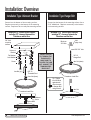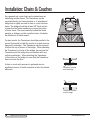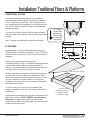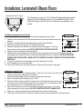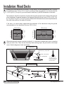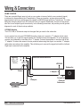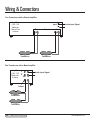
1
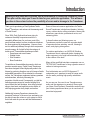
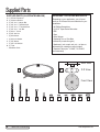
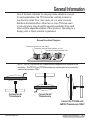
CLARK SYNTHESIS
TACTILE SOUND®
Installation Guide
• TST429-Platinum Transducer
• TST329-Gold Transducer
• TST239-Silver Transducer
• AW339-All Weather Transducer
For accessories and other helpful information, visit our
web site
www.clarksynthesis.com
Table of Contents
CAUTION: THIS TRANSDUCER
CONTAINS AN EXTREMELY POWERFUL
MAGNET. DO NOT PLACE IN CLOSE
PROXIMITY TO TUBE TV MONITORS, TUBE
VIDEO MONITORS, AND MAGNETIC MEDIA.
Important Product Information
Introduction
Supplied Parts
Installation: Overview
Installation: Chairs and Couches
Installation: Traditional Floors and Platforms
Installation: Laminated I-Beam Floors
Installation: Wood Decks
Wiring and Connections
Troubleshooting
Warranty and Returns
2
3
4
6
8
9
10
12
14
18
19
! IMPORTANT PRODUCT INFORMATION
1. DO NOT DROP THE TRANSDUCER- The Transducer can be damaged both internally and externally if
dropped. Damage caused by dropping the Transducer is not covered under the warranty.
2. DO NOT EXPOSE THE TRANSDUCER TO HIGH DISTORTION LEVELS- Exposing the Transducer to
high levels of distortion may damage the unit. This type of damage is not covered under the warranty. If
the Transducer stops playing, it is likely that the built-in protection circuit has activated. In the event this
happens, turn the amplifier off for approximately 60 seconds to allow the circuit to reset. Turn down the
volume on the input signal and amplifier. Operate the system at lower volume levels to avoid overloading
the Transducer.
3. USE CAUTION WHEN INSTALLING IN FURNITURE- If using this Transducer on a chair, sofa, or
couch, insure the Transducer is protected from hitting the floor and from entanglement with any recliner
components. Severe damage may occur to the wiring. This type of damage is not covered under the
warranty.
4. CABLE PLACEMENT- Use caution when running the cable from the amplifier to the Transducer. Do not
lay the cable in high-traffic areas where tripping or entanglement may occur.
5. DO NOT CARRY THE TRANSDUCER BY THE CABLE- Never carry the Transducer by its cable. This
can damage the strain relief and internal wiring of the Transducer. Damage of this type will not be covered
under the warranty.
6. DO NOT REMOVE THE STRAIN RELIEF- Removing or altering the strain relief fitting connecting the wire
to the thumper may permanently damage the Transducer. This fitting is carefully installed at the factory.
Any alteration or adjustment of this fitting will void the warranty.
7. AVOID EXCESSIVE HEAT- Exposure to excessive heat will result in internal temperatures that can cause
damage to the components. Damage caused by neglect will not be covered under warranty.
8. STORAGE- Insure the components are adequately protected when storing or transporting.
9. USE PROPER AMPLIFICATION- Insure the Transducer is being powered by an amplifier that is stable at
4 ohms and delivers at least 100 to 150 watts into 4 ohms per Transducer.
10.EXTERNAL VOLUME CONTROLS- Do not use with external volume controls rated at less than 100
watts.
2
Tactile Sound Transducers
www.clarksynthesis.com
Introduction
Before you drill holes and run wires, take a few moments to review this Installation Guide.
Then plan out the steps you’ll need to take for your particular application. This will save
you time in the end and reduce the possibility of errors and/or damage to the Transducer.
Thank you for purchasing a Clark Synthesis Tactile
Sound® Transducer, and welcome to the amazing world
of Tactile Sound!
Since 1994, Clark Synthesis has been giving its
customers the ability to experience sound in a
completely different way. As you know, most of the
sound we hear reaches our ears via airborne vibrations,
like those produced by loudspeakers. However, there
are four additional pathways through which we perceive
acoustic energy, all of which fall into the category of
tactile sound. These additional pathways include:
• Deep tissue and muscle mass
• Skeletal Joints
• Skin Sensation
• Bone Conduction
To capitalize on these additional means by which we
perceive acoustic energy, Tactile Sound Transducers
have been designed to send high-quality audio to the
listener by producing vibrations over a full range of tactile
and audible frequencies. When attached to a resonant
surface, the Transducers supplement ordinary speakers
and subwoofers, effectively increasing the
proportion of tactile sound. Consequently, you feel the
natural percussive impact of sounds, bringing life to
sound effects like hard footsteps, door slams, plucked
strings, drum beats, and explosive movie effects, all
while enjoying greater clarity, depth, and realism.
Additionally, because Transducers increase the
perceived “loudness” of the sound you are hearing, you
are able to lower the volume on your system to a level
that is both safer for your ears and less bothersome to
neighbors.
www.clarksynthesis.com
Some of the most common applications for Tactile
Sound Transducers include home theaters, listening
rooms, outdoor decks, military simulators, theme park
attractions, game chairs, professional music, and
swimming pools.
In home theaters and listening rooms, our
Transducers provide the user with a greater depth
of experience when watching movies, listening to
music, and playing video games.
For outdoor applications, our AW339 All Weather
Transducers mount underneath decks, keeping the
audio equipment out-of-sight while transferring audio
to the surface of the deck.
Many military and flight simulator companies use our
TST329 Gold Transducers to bring a greater sense of
realism to training exercises.
Pool enthusiasts use our AQ339 Aquasonic™
underwater pool speakers to send full-range audio
into the water, providing high-quality underwater
music.
As you can see, the uses for our Transducers are
many and the experience is amazing! We are glad
you chose Clark Synthesis Transducers and we hope
your listening experience takes you to new levels of
acoustical enjoyment!
Tactile Sound Transducers
3
Supplied Parts
SUPPLIED PARTS (ILLUSTRATED BELOW)
REQUIRED TOOLS AND MATERIALS
A. (1) TST209 Transducer
B. (1) Unimount Bracket
C. (1) 3/8”-16 x 3” Hanger Bolt
D. (1) 3/8”-16 x 3” Threaded Stud
E. (1) 3/8”-16 x 1.5” Threaded Stud
F. (1) 3/8”-16 x 1” Hex Bolt
G. (4) #12 x 1” Screw
H. (2) 3/8” Jam Nut
I. (4) #12 Washer
J. (4) #12 Lock Washer
K. (1) 3/8” Washer
L. (1) 3/8” Lock Washer
M. (1) T-Nut
• Installation Guide
Depending on your application, you will need
some or all of these tools and materials for your
installation:
• #2 Phillips Screwdriver
• (2) 9/16” Open-Ended Wrenches
• Drill
• Saw
• Wire Stripper
• Soldering Gun or Wire Nuts
• Adhesive (construction glue)
• Hardwood (oak, maple, ash, etc., not pine or
softwoods) for creating mounting bridges
• Speaker Cable (min. 16 AWG; 12-14 AWG
recommended)
Side View
B
A
3-D View
Front View
C
4
D
E
Tactile Sound Transducers
F
G
H
I
J
K
L
M
www.clarksynthesis.com
General Information
One of the best materials for carrying tactile vibrations is wood.
In most applications, the TST should be centrally located on
the structure (chair, floor, riser, deck, etc.) in order to evenly
distribute the tactile effect. When two or more TSTs are used
on one structure, they should be spaced equidistant from each
other and the edges/boundaries of the structure. Mounting to a
bridge, joist, or frame member is preferred.
General Location Diagram
Transducer mounted to chair frame
Transducer mounted inside platform or riser
Transducer mounted beneath floor
NOTE: The TST329 and AW339 Transducers are designed to be mounted in any
orientation. The TST239 and TST429 transducers are designed to be mounted in
a horizontal orientation ONLY.
Correct for all
Transducers
Correct for all
Transducers
Correct for TST329 and
AW339 Transducers ONLY
www.clarksynthesis.com
Tactile Sound Transducers
5
Installation: Overview
Installation Type: Unimount Bracket
Installation Type: Hanger Bolt
Screws into the bottom of the mounting surface.
Requires access only to the bottom of the mounting
surface. Requires a flat or nearly flat mounting surface.
Minimum 4-1/2” vertical space required,
including 1/2” clearance between the
Transducer and the floor.
Screws into the bottom of the mounting surface (into a
5/16” drilled hole. Requires access only to the bottom
of the mounting surface.
Minimum 3-1/2” vertical space required,
including 1/2” clearance between the
Transducer and the floor.
3/4”-thick
mounting
surface
Minimum
3/4”-thick
Joist
(edge view)
Drill 5/16” hole
Unimount
Bracket
NEVER TIGHTEN
BY TURNING THE
TRANSDUCER.
MAKE SURE TO
TIGHTEN THE JAM
NUT AGAINST THE
TRANSDUCER’S
BRASS NUT
Flat Washer
Lock Washer
Screw
Jam Nut (up)
3/8”-16
Hanger Bolt
Jam Nut (down)
3/8”-16
Threaded Stud
Jam Nut (down)
Transducer Lead Wire
Tip: Tighten
two Jam Nuts
against each
other to screw
in Hanger Bolt
using wrench.
Transducer Lead Wire
Jam Nut
Washers
Screw
Jam Nuts
6
Tactile Sound Transducers
www.clarksynthesis.com
Installation: Overview
Installation Type: T-Nut
Installation Type: Hex Bolt
Requires initial access to the top of the material to
insert the T-Nut, which installs flush to the surface.
(Drill a 7/16” hole for the T-Nut.)
Minimum 3-1/2” vertical space required,
including 1/2” clearance between the
Transducer and the floor.
For use with metal or other high-tensile mounting
surfaces no thicker than 1/4”. Requires access to the
top of the mounting surface both to install the bolt and
to tighten it.
Minimum 3-1/4” vertical space required,
including 1/2” clearance between the
Transducer and the floor.
Drill 7/16” hole
3/4”-thick
mounting
surface
Drill 7/16” hole
T-Nut
Flat Washer
Lock Washer
Jam Nut (up)
3/8”-16
Threaded Stud
Jam Nut (down)
NEVER TIGHTEN
BY TURNING THE
TRANSDUCER.
MAKE SURE TO
TIGHTEN THE JAM
NUT AGAINST THE
TRANSDUCER’S
BRASS NUT
Maximum 1/4”-thick
mounting
surface
3/8”-16
Hex Bolt
Flat Washer
Lock Washer
Jam Nut (up)
Jam Nut (down)
Transducer Lead Wire
Transducer Lead Wire
Flat Washer
Washers
Jam Nuts
www.clarksynthesis.com
Lock Washer
Jam Nuts
Tactile Sound Transducers
7
Installation: Chairs & Couches
As a general rule, most chairs and couches have an
underlying wooden frame. The Transducer can be
mounted directly to a frame member or to a hardwood
bridge that is rigidly secured to chair or couch’s bottom
frame. The bridge should be at least 3/4" thick and cut
to span the two frame members or connect two sides
of a box frame. The more centrally located the frame
member or bridge is on the overall structure, the better
the distribution of tactile sound.
Hardwood Bridge (min. 3/4” thick)
For best results, the Transducer should be parallel to the
ground (horizontal) so that the motion is up and down as
opposed to sideways. The Transducer can be mounted
to either the top or bottom of the bridge. When attaching
the Transducer to the top of the bridge, be sure that the
Transducer and the wiring does not interfere with any
recliner mechanism. When attaching the Transducer
to the bottom of the bridge, be sure that the Transducer
does not touch the floor.
A chair or couch with armrests is preferred since a
significant amount of tactile sensation is felt in the hands
and arms.
Transducer mounted
under the bridge
Transducer mounted
over the bridge
8
Tactile Sound Transducers
www.clarksynthesis.com
Installation: Traditional Floors & Platforms
TRADITIONAL FLOORS
Transducers may be mounted under a floor by attaching a
hardwood bridge between adjacent floor joists, or by installing
a 2” x 6” bridge with a curved niche. When installing under a
floor, access may be from the basement or the ceiling below the
floor. The TST will be mounted to a bridge connected between
adjacent floor joists.
If your goal is to excite the area of the floor directly beneath a
chair, then attach the Transducer to the closest joist underneath
the chair.
Note: Carpeting and padding may reduce the tactile effect.
Tip: Tighten
two Jam Nuts
against each
other to screw
in Hanger Bolt
using wrench.
Mounting Detail
PLATFORMS
Recommendation: Clark Synthesis recommends using only
TST429 Platinum Transducers for platforms. Use of (1) TST429
Platinum Transducer for every 4 ft. by 8 ft. area of the platform is
suggested.
2” x 6” Bridge with Curved Niche
3”
Jam Nut
6”
Platforms are a great alternative to mounting a
Transducer directly to a chair. This method is especially practical
in home theaters with multiple rows of seating placed on
platforms. An activated platform will deliver tactile sensations to
your feet as well as the rest of your body via the chair.
Glue and screw all joints
Whether constructing a new platform or fitting Transducers onto
an existing one, it is best to space the Transducers an equal
distance from each other and the edges of the platform. If using
only one Transducer, locate the Transducer in the center of
the platform. Be sure to leave a way to access the Transducer
should service be required.
To minimize energy loss into the floor, use Isolation Feet
between the platform and the floor. Do not glue a platform to a
concrete floor.
Clark Synthesis recommends using plywood or hardwood for the
platform’s top surface. DO NOT USE MDF (medium-density
fiberboard). We highly recommend using adhesive and
screws instead of nails. Loose fitting joints can cause unwanted
vibrations and buzzing noises.
www.clarksynthesis.com
Glue and screw
plywood floor surface
to all frame members
including the bridge
Tactile Sound Transducers
9
Installation: Laminated I-Beam Floors
Laminated I-Beam Joists
The Transducer mounts on 1"x 6" hardwood bridge spanning two joists,
using the Unimount Bracket (shown) or the threaded stud with T-Nut.
Attach the bridge to the bottom face of the joists using adhesive and
screws.
Installation using the Unimount Bracket
MOUNTING DETAIL
1. Attach a 1” by 6” hardwood bridge to the two I-beams using adhesive and screws.
2. Attach the Unimount Bracket to the bridge using machine screws with flat washers and lock
washers.
Washers
3. Screw the a Threaded Stud into the threaded insert on the Unimount Bracket.
Screws
Jam Nuts
4. Spin the two Jam Nuts onto the stud. You will tighten them later.
5. Screw the Transducer onto the Stud until a slight resistance is felt (approx. 5 or 6 turns).
When resistance is felt, stop turning. DO NOT OVERTIGHTEN THE TRANSDUCER!
6. Tighten one Jam Nut against the Unimount Bracket.
7. Tighten the other Jam Nut against the Transducer’s brass nut using two 9/16” wrenches as follows: One wrench
firmly grasping the Transducer’s brass nut while the second tightens the Jam Nut against it. NEVER TIGHTEN BY
TURNING THE TRANSDUCER – MAKE SURE TO TIGHTEN THE JAM NUT AGAINST THE TRANSDUCER’S
BRASS NUT.
8. Use solder or wire nuts to connect speaker wire to the Transducer’s wire leads.
9. Run the speaker wire to your audio system.
10. Connect the Transducer to your audio system (see “Wiring and Connections” in this guide).
Installation using the T-Nut
MOUNTING DETAIL
1. Drill a 7/16” hole in a 1” by 6” hardwood bridge. Press the T-nut into the hole on the side
of the mounting surface opposite the Transducer.
T-Nut
1. Attach the hardwood bridge to the two I-beams using adhesive and screws.
2. Screw a Threaded Stud completely into the T-Nut.
Washers
Jam Nuts
3. Place the 3/8” flat washer and 3/8” lock washer on the Threaded Stud, then spin the two
Jam Nuts onto the stud (flat washer against the mounting surface, lock washer between
flat washer and jam nut). You will tighten the jam nuts later.
4. Screw the Transducer onto the Stud until slight resistance is felt (approx. 5 or 6 turns).
When resistance is felt, stop turning. DO NOT OVERTIGHTEN THE TRANSDUCER!
5. Tighten one Jam Nut against the lock washer, flat washer, and mounting surface.
6. Follow steps 6 through 9 under “Steps for installation using the Unimount Bracket” (as shown above).
10
Tactile Sound Transducers
www.clarksynthesis.com
Notes
www.clarksynthesis.com
Tactile Sound Transducers
11
Installation: Wood Decks
1
Measure the overall dimensions of the deck. For best results, it is recommended that one (1) AW339
be installed for every 10 ft. by 10 ft. (3 m by 3 m) section of deck. For example, if you have a deck that
is 10 ft. by 20 ft. (3 m by 6 m), you would need to install two (2) AW339 transducers on that deck.
The transducer should be mounted in a location that is equally spaced from the sides of the deck and
other transducers. As general examples, the diagrams below provide top views of 10 ft. by 10 ft. (3 m
by 3 m) and 10 ft. by 20 ft. (3 m by 6 m) deck surfaces with the transducers mounted equal distances
from each other and from the edges of the deck.
If the deck is a custom shape, approximate the placement of the transducers using the general
recommendation of one transducer for every 100 ft.2 (9 m2).
10 ft. (3 m)
Transducer
Transducers
6.7 ft.
6.7 ft.
6.7 ft.
(2.05 m) (2.05 m) (2.05 m)
5 ft.
5 ft.
(1.5 m) (1.5 m)
2
5 ft.
5 ft.
(1.5 m) (1.5 m)
20 ft. (6 m)
5 ft.
5 ft.
(1.5 m) (1.5 m)
10 ft. (3 m)
10 ft. (3 m)
When determining the actual mounting location(s), it is important to decide which type of mounting
style you want to use. There are two commonly used mounting styles: the joist mount or the bridge
mount. See the diagrams of each style below.
Joist Mount
Minumum 3/4” (1.9 cm) Thick
Joist
Jam Nut
Drill 5/16” (.79 cm) Hole
3/8”- 16 Hanger Bolt
Tip: Tighten two Jam
Nuts against each other
to screw in the Hanger
Bolt with a wrench.
Bridge Mount
Straight Bridge
3” (7.6 cm)
Arched Bridge
12
Tactile Sound Transducers
Jam Nut
Nut
Jam
5-1/2” (14 cm)
www.clarksynthesis.com
3
Installation: Wood Decks
If you are using the joist mount, determine the general mounting location and then find the closest
joist support for that location. Drill a 5/16” (.79 cm) pilot hole that is approximately 2 inches (5 cm)
deep into the joist. Place two (2) Jam Nuts on the Hanger Bolt and tighten the nuts together (see the
joist style diagram on the previous page). Turn the Hanger Bolt into the joist up to the place on the
bolt where the threads change from wood threads to machine threads. Loosen and remove one of
the Jam Nuts.
Lifting the transducer up to the Hanger Bolt, place the transducer’s brass mounting nut onto the
machine thread side of the Hanger Bolt. Insuring not to cross-thread the Hanger Bolt into the brass
nut, gently turn the transducer 5 to 6 complete revolutions. If you feel resistance, stop immediately.
CAUTION: DO NOT OVERTIGHTEN.
Spin the Jam Nut that is still on the Hanger Bolt down to the brass nut and, using two wrenches (one
on the Jam Nut and one on the brass nut), tighten the Jam Nut against the brass nut.
CAUTION: DO NOT TIGHTEN THE JAM NUT TO THE BRASS NUT BY TURNING THE
TRANSDUCER. THIS WILL RESULT IN SEVERE DAMAGE TO THE TRANSDUCER AND WILL
VOID THE WARRANTY.
4
If you are using the bridge mount, determine which type of bridge you want to use (straight or arched).
If you are using the arched bridge style, cut the arch using the dimensions shown on the previous
page.
Cut the length of the bridge board to fit snugly between the two support joists. The bridge board must
be at least 3/4” (1.9 cm) thick. Screw the bridge board securely between the support joists. Follow the
directions for installing the Hanger Bolt and the transducer under Step 3, above.
5
Once the transducer is mounted to the Hanger Bolt, run exterior grade speaker wire from your audio
equipment (receiver and/or amplifier) to the wire lead on the transducer. Connect the wires, insuring
the splice is as waterproof as possible. Your AW339 All-Weather transducer is now ready to enjoy.
www.clarksynthesis.com
Tactile Sound Transducers
13
Wiring & Connections
HOME THEATER
There are several different ways to hook up your system in terms of which source material (signal)
is delivered to the amplifier(s) and Transducer(s). Since our inception, we have discovered that
approximately half of our customers prefer using the LFE/SUB signal with their Transducers. The other
half prefer using the Right Front (RF) and Left Front (LF) signals. Additionally, there are a few people
who like to use multiple signals concurrently. In the following instructions, we provide you with general
diagrams for each of these hookup methods.
LFE/SUB Hookup
The LFE, SUB, or Subwoofer output is the signal that you send to the subwoofer.
If your receiver has only one LFE/SUB/Subwoofer output port, connect a “Y” adapter to that output.
This will allow you to split the signal between the Transducer and the subwoofer. To do this properly,
connect your subwoofer to one side of the “Y” adapter. Connect the amplifier to the other side of the
“Y” adapter. To reduce the amount of noise produced when using this signal, use another “Y” adapter
cable when connecting to the amplifier. This will allow you to connect the signal into both the Left and
Right input connectors on the amplifier.
Amplifier
(100 - 150
Watts into
4 ohms)
Surround-Sound Receiver
L
R
OUT IN
–
LFE/SUB
+
Subwoofer
Output
Y Adapter
Y Adapter
To Input of
Powered
Subwoofer
Transducer
14
Tactile Sound Transducers
www.clarksynthesis.com
Wiring & Connections
Right Front (RF) and Left Front (LF) Hookup
For this hookup, connect the RF and LF Pre-Amp Outputs to the amplifier inputs.
NOTE: Not all receivers have Pre-Amp outputs for the Right Front and Left Front outputs. If you
have a question about your receiver’s outputs, please consult your owner’s manual or contact your
receiver’s manufacturer.
Amplifier
(100 - 150
Watts into
4 ohms)
L
R
OUT IN
–
Surround-Sound Receiver
Pre-Amp Audio Out
LF
RF
+
Output
Transducer
Multiple Signal Hookup
This configuration is a little more complicated. You will need a small mixer to make this work.
Connect the signals you want to use to the mixer input. Then, connect the mixer output to the
amplifier input using a “Y” adapter.
Amplifier
(100 - 150
Watts into
4 ohms)
L
R
OUT IN
–
Surround-Sound Receiver
Pre-Amp Audio Out
LF
CENTER
RF
LFE/SUB
+
Output
CH1
CH2
CH3
CH4
OUTPUT
Transducer
Mixer
Y Adapter
www.clarksynthesis.com
Tactile Sound Transducers
15
Wiring & Connections
Two Transducers with a Stereo Amplifier
Amplifier
(100 - 150
Watts per
Channel into
4 ohms)
Input
R
–
Transducer
Output
L
–
+
Audio Input Signal
+
Transducer
Two Transducers with a Mono Amplifier
Amplifier
(120 - 150
Watts into
8 ohms)
L
R
Audio Input Signal
OUT IN
–
+
Output
Transducer
Transducer
16
Tactile Sound Transducers
www.clarksynthesis.com
Notes
www.clarksynthesis.com
Tactile Sound Transducers
17
Troubleshooting
Symptom
No Tactile Sound
Not Enough Tactile Sound
Troubleshooting Question
Remedy
Is the Transducer connected?
Connect the Transducer properly.
Is the input source connected to the
amplifier input?
Connect the input source.
Is the source outputting a signal?
Connect the source to another amplifier
to verify the source is working.
Is the Gain (Volume) Control turned up?
Slowly turn up the Gain (Volume) Control.
Is the amplifier properly matched to the
Transducer?
Make sure the amplifier is powerful
enough and stable with a 4 ohm load.
Did the Transducer stop working?
Turn the Gain Control down, wait a few
minutes, then try again.
Is the Gain (Volume) Control adjusted
properly?
Turn up the source volume and the
amplifier’s gain (volume) control.
Is the amplifier properly matched to the
Transducer?
Make sure the amplifier is powerful
enough and stable with a 4 ohm load.
Is the Transducer not powerful enough for Add another Transducer. Use a more
your application?
powerful Transducer.
Sound Comes and Goes
Did the Transducer output suddenly
decrease or did the Transducer stop
working?
Turn the Gain Control down, wait a few
minutes, then try again.
Is the amplifier properly matched to the
Make sure the amplifier is powerful
enough and stable with a 4 ohm load.
Transducer?
I Hear a Rattling or Buzzing Are all hardware components tightened
Noise
down?
I Hear Noises from my
Recliner
18
Tactile Sound Transducers
Tighten all screws and jam nuts.
Is the Transducer touching anything?
Make sure the Transducer body is not
touching any surfaces.
Is the signal to the Transducer clipping?
Make sure that the signal to the
Transducer is not clipped. Try turning
down the original signal.
Is the recliner “loose”?
Check to make sure that all recliner
hardware is tightened. Try wrapping
waxed dental floss in the footrest scissor
hinges to dampen the vibrations.
Is the Transducer connected to the
surround receiver’s center channel?
Connect the Transducer’s receiver to
either the LFE/Subwoofer signal, or to
the LF/RF signals. (Note: Some DVDs
contain voices in the LF/RF signals)
www.clarksynthesis.com
Warranty & Returns
United States Warranty and Return Policy
TST429, TST329, TST239, AW339 Transducer WARRANTY
Clark Synthesis, Inc. warranties the TST239, TST329, TST429, and AW339 Transducers to be free
from defects and workmanship under normal use for a period of two (2) years from date of original
purchase. For industrial or commercial use, the warranty period is six (6) months.
This warranty is valid for the original purchaser and is not extended to subsequent owners. Any
applicable implied warranties are limited in duration to a period of the express warranty as provided
herein beginning with the date of the original purchase at retail, and no warranties, whether
expressed or implied, shall apply to this product thereafter. Some states do not allow limitations on
implied warranties; therefore these exclusions may not apply to you. This warranty gives you specific
legal rights; however, you may have other rights that vary from state to state.
WHAT IS NOT COVERED
This warranty is valid only if the product is used for the purpose for which it was designed. It does
not cover the following:
• Damage caused by excessive heat
• Damage through negligence, misuse, accident, or abuse
• Damage caused by incorrectly mounting the Transducer
• Damage due to not using an appropriate amplifier
• Freight damage
• Items repaired by an unauthorized repair facility
• Items damaged due to amplifier clipping and/or distortion
• Items purchased from unauthorized individuals or dealers
• Cost of shipping product to Clark Synthesis, Inc.
• Return shipping on non-defective items
RETURN POLICY
New, unused transducers may be returned within 7 days of the purchase date or the date of receipt.
Returns must be in their original packaging, undamaged, and in resellable (new) condition. All
hardware and manuals must be included. If the returned transducer does not meet these conditions,
you will be charged a 15% restocking fee or have the transducer returned to you at your expense.
Shipping charges are not refundable.
WHAT TO DO IF YOU NEED WARRANTY OR SERVICE
Contact Clark Synthesis at 303-797-7500, or email us at [email protected]. You will be
given a Return Authorization (RA) number and return instructions.
International Warranty and Return Policy
Contact your international Clark Synthesis dealer or distributor for your country’s warranty policies.
www.clarksynthesis.com
Tactile Sound Transducers
19
© 2009 Clark Synthesis, Inc. All Rights Reserved.
11/2009
Clark Synthesis, Inc.
Telephone: 303.797.7500
Fax: 303.797.7501
Email: [email protected]
www.clarksynthesis.com
www.clarksynthesis.com