1
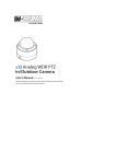
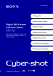
INSTALLATION
Mount the Camera
Prepare the Camera
Using the desired Wall or Ceiling Mount, secure camera’s Mounting Box
to wall/ ceiling.
Connect and secure all necessary cables from
the inner box to all desired applications
Connect the RS-485 wires to a terminal box
matching the inner box RS-485 terminals.
Connect the other end of the cable to a terminal
box matching the DVR or keyboard controller’s
RS-485 Terminals.
1
x39 Analog PTZ Outdoor
INSTALLATION
INSTALLATION
12
4
Unscrew the top cover of the mounting box
and remove the protective plastic to expose
the four screw holes
5
Snap the camera mechanism back into the upper
housing.
13
Make sure the two black handles marked ‘A’
and ‘B’ correspond with the ‘A’ and ‘B’ markings
on the sides of the upper housing.
Note: Before snapping the camera back into
the housing, make sure all cables are
properly secured.
15
Connect the cover dome to the upper housing
by securing the safety wire.
Using the mounting box or the mounting template
mark on the wall or ceiling the locations for the
four bolts.
AC
Adapter
Wall(Ceiling) Mount Camera
Quick Start Guide
14
Version 1.01
Connect BNC Coaxial cable to camera’s inner box.
Connect other end of the BNC cable to a DVR
or monitor.
4
3
Connect ACPower Adapter to the camera’s
Inner box. Make sure to connect positive and
negative lines in their corresponding locations.
2
This equipment has been tested and found to comply with the limits for a Class A digital device, pursuant to part 15 of the FCC Rules.
These limits are designed to provide reasonable protection against harmful interference when the equipment is operated in a
commercial environment. This equipment generates, uses, and can radiate radio frequency energy and, if not installed and used in
accordance with the instruction manual, may cause harmful interference to radio communications. Operation of this equipment in a
residential area is likely to cause harmful interference in which case the user will be required to correct the interferenece at his own
expense.
3
PREPARATION
INSTALLATION
The following items are included with the PTZ camera
DIP Switch Setup
1 AUTO- Factory Default
Mounting Box
8J 1
3
4
5
6
7
8
8J 1
3
4
5
6
7
8
INSTALLATION
Waterproof Tape
8J 1
2
3
4
5
6
7
8
8J 1
Inner Box
8J 1
2
3
4
5
6
7
8
8J 1
2
3
4
5
6
7
8
ON
8
8J 1
8J 1
2
3
4
5
6
7
2
3
4
5
6
7
8
TEL: (866) 446-4359
www.Digital-Watchdog.com / [email protected]
Technical Support Hours: Monday-Friday 8:30AM to 8:00PM EST
3
4
5
6
7
8
12 0 5 2 0 1 1
7
8
RS-485
Termination Resistor
Pass the cable connector from the inner box
through the upper housing pipe.
If inner box is located in teh upper housing,
connect the desired mounting bracket and run
the wires through the bracket.
9
Screw the upper housing to the mounting box/
bracket. Turn the upper housing at least seven (7)
times to secure a tight connection.
For outdoor installation, wind the weatherproof tape
around the upper housing’s pipe.
9
8J 1
2
3
4
5
6
7
8
8J 1
2
3
4
5
6
7
8
Camera’s ID
Using the bottom DIP Switch, setup the
camera’s ID. By default, the camera’s ID
2
3
4
5
6
7
8
ON
2
6
ON
2
7 AD (American Dynamics)
8J 1
5
When setup is complete, Home Position will show OK
ON
Thank you for purchasing Digital Watchdog’s Super Speed Dome PTZ Outdoor Dome Camera.
Before installing the camera, please verify your model and read this guide carefully.
4
Baud Rate Setup
8
6 GE(Kalatel)
Safety Wire
3
5 38400 BPS
ON
8J 1
2
Protocol Setup
ON
5 PANASONIC
8J 1
Anchor Bolt (4pcs)
Connect the camer to the power and make sure it is operating
properly.
When System Initialize screen appear, take note of the camera’s
protocol, Baud Rate and Address. This information will be necessary
to complete camera’s connection to a DVR or Keyboard Joystick.
4 19200 BPS
ON
Housing Safety
Cable Hanger
Bit Rate
ON
4 SAMSUNG
Inner Box (Found in the upper
housing or mounting box)
INSTALLATION
Connet power and initial testing
3 9600 BPS - Factory Default
ON
Hexagonal Wrench
7
ON
2
3 PELCO-P
Covering Dome
5
2 4800 BPS
ON
CD (Manual)
If camera model includes the inner box inside the mounting
box, make sure all cables remain intact during installation
ON
2
2 PELCO-D
Upper Housing
Remove PTZ mechanism from the upper housing.
To detach mechanism from upper housing,
press down and hold both black handles marked
‘A’ and ‘B’ on the camera mechanism.
Pull both handles up to detach the camera.
1 2400 BPS
ON
PTZ39X Manual
7
Using the DIP Switch in the inner box, setup the camera’s
Communication Protocol, Joystick Controller, and cmaera’s ID.
Communication
Protocol
Hole Template
Using a drill, drill four holes for the bolts and
secure mounting box to wall/ceiling.
!
To disconnect power from the mains, pull out the mains cord plug.
When install the product, ensure that the plug is easily accessible.
Camera Module
6
Remove protecting gear from the camera’s lens
RS-485 Termination
Resistor
3
4
5
6
7
8
8J 1
by turning switches ON or OFF.
Each switch has a numerical value. The
10
11 Plug cable connector from the inner box
Hook the safety wire to the safety hook on the
to the upper housing.
upper housing. Using the safety hanger, secure it
to the mounting box/ bracket.
17
camera’s ID = the sum of all switches
ON
2
is set as 1. Users can select 1~255 IDs
2
3
4
5
6
7
8
that are turned ON.
!
4
6
If no adjustments need to be made to the
wiring, place the dome cover on the upper
housing.
18
Secure dome to camera by fastening the screws
on the dome in the order shown here.
This order of fastening the screws guarantees optimal
sealing and protects the camera from weather elements
8
Preset 95
Some preset numbers are reserved to special functions.
Preset 95 is reserved for starting the camera’s OSD menu.
For a complete list of all the reserved presets, see the PTZ39X’s
complete manual or page 14.
Accessing the OSD Menu
1
Select Full Screen view on the selected PTZ camera
2
Right-Click the screen & Select ‘PTZ’
3
Right-Click the screen again, & select ‘Preset’
Up
Left
Right
Enter 95 to access the OSD menu
5
and/or scans. Maximum 8 group can be stored. Each group can
have max 20 actions.
When the scan function runs, the camera moves from the
preset assigned as the 1st point to the preset assigned as the
2nd point in CW(Clockwise) direction. Then the camera moves
from the preset assigned as the 2nd point to the preset
assigned as the 1st point in CCW(Counterclockwise) direction.
Users can setup 1~8 different scans.
To setup a scan, at least two (2) presets must be setup.
Preset key + 95: Enters into OSD menu
Preset key + 131~134: Runs pattern function 1 ~ 4
Preset key + 141~148: Runs scan function 1 ~ 8
Preset key + 151~158: Runs group function 1 ~ 8
Preset key + 161~164: Sets relay 1~ 4 output to OFF
Set key + 161~164: Sets relay 1~ 4 output to ON
Preset key + 165: Sets auto calibration to ON
Preset key + 166: Sets auto calibration to OFF
Preset key + 167: Zoom proportional jog ON
Set key + 167: Zoom proportional jog OFF
Preset key + 170: Sets camera BLC mode to OFF
Preset key + 171: Sets camera BLC mode to HIGH
Preset key + 174: Sets camera focus mode to AUTO
Preset key + 175: Sets camera focus mode to MANUAL
Preset key + 176: Sets camera focus mode to SEMI-AUTO
Preset key + 177: Sets day & night mode to AUTO
Preset key + 178: Sets day & night mode to NIGHT
Preset key + 179: Sets day & night mode to DAY
Preset key + 190: Sets OSD display mode to AUTO (except privacy mask)
Preset key + 191: Sets OSD display mode to OFF (except privacy mask)
Preset key + 192: Sets OSD display mode to ON (except privacy mask)
Preset key + 193: Sets all privacy mask display to OFF
Preset key + 194: Sets all privacy mask display to ON
Preset key + 200: Sets digital zoom to ON
Preset key + 201: Sets digital zoom to OFF
Using mouse, click on area of the screen
labeled:
UP: to scroll up the menu
DOWN: to scroll down the menu
Left: Vertically move from one edit tab
to the one to its left
RIGHT: Vertically move from one
edit tab to the one to its right.
9
OSD MENU
The group function allows you to run sequence of presets, pattern,
By using the scan function, you can make the camera to move
between 2 preset positions repeatedly.
To setup a group, at leaset 1 preset, 1 scan, 1 pattern must be setup.
FUNCTION SETUP
- - - - - - - - - - - - - - - - - - - <PRESET SETUP>
<SCAN SETUP>
<PATTERN SETUP>
<GROUP SETUP>
<SCHEDULE SETUP>
- - - - - - -
1st POS.
EDIT GROUP
1
- - - - - - - - - - - - - - - - - - - - - - - - - - -
NO. ACTION NO. DWELL OPT
- - - - - - - - - - - - - - - - - - - - - - - - - 1 NONE
2 NONE
3 NONE
4 NONE
5 NONE
- - - - - - - - - - - - - - - - - - - - - - - - - SAVE
[NEAR:EDIT ACT]
CANCEL [FAR :EDIT END]
1. CW direction
FUNCTION SETUP
- - - - - - - - - - - - - - - - - - - <PRESET SETUP>
<SCAN SETUP>
<PATTERN SETUP>
<GROUP SETUP>
<SCHEDULE SETUP>
- - - - - - -
SCAN SETUP
- - - - - - - - - - - - - - - - - - - - - - - - - - -
BACK
EXIT
SCAN
NO.
1ST POS.
2ND POS.
1
NOT USED
NOT USED
SCAN SPEED
CLEAR SCAN
30/SEC
CANCEL
Select the first action in the group.
Click with the mouse on the right side
of the screen to enter edit mode.
BACK
EXIT
In the Root Menu,
go to Function Setup> Scan Setup
EDIT GROUP
1
- - - - - - - - - - - - - - - - - - - - - - - - - - -
NO. ACTION NO. DWELL OPT
- - - - - - - - - - - - - - - - - - - - - - - - - 1 PATTERN 1 00:03 1
2 NONE
3 NONE
4 NONE
5 NONE
- - - - - - - - - - - - - - - - - - - - - - - - - SAVE
[ :MOVE CURSOR]
CANCEL [ : CHANGE VAL.]
Set up the 2 position for scan function.
If a selected preset is not defined, ‘UNDEFINED’
will be displayed as shown.
Using the mouse, continue editing the desired
information. Enter the action’s number, Dwell
time between each action, and the numebr of
repetitions under OPT.
11
13
PATTERN SETUP
PRESET SETUP
- - - - - - - - - - - - - -
1
UNDEFINED
CANCEL
BACK
EXIT
In the Root Menu,
go to Function Setup> Group Setup
2. CCW direction
GROUP SETUP
- - - - - - - - - - - - GROUP NO.
CLEAR GROUP
<EDIT GROUP>
BACK
EXIT
2nd POS.
Down
4
GROUP SETUP
SCAN SETUP
RESERVED PRESETS
OSD MENU
Select the Group you wish to modify. If a group
is not defined, ‘UNDEFINED’ will be displayed
as shown.
EDIT GROUP
1
- - - - - - - - - - - - - - - - - - - - - - - - - - -
NO. ACTION NO. DWELL OPT
1 NONE
2 NONE
3 NONE
4 NONE
5 NONE
- - - - - - - - - - - - - - - - - - - - - - - - - SAVE
[ :MOVE CURSOR]
CANCEL [ : CHANGE VAL.]
- - - - - - - - - - - - - - - - - - - - - - - - - -
Using the mouse, click on the top and bottom of the
screen to scrol down the options. Select from
Preset, Pattern, Scan. Click on the right side of the
screen to save selection and move to the next tab to
the right.
EDIT GROUP
1
- - - - - - - - - - - - - - - - - - - - - - - - - - -
NO. ACTION NO. DWELL OPT
- - - - - - - - - - - - - - - - - - - - - - - - - 1 PATTERN 1 00:03 1
2 NONE
3 NONE
4 NONE
5 NONE
- - - - - - - - - - - - - - - - - - - - - - - - - [NEAR:EDIT ACT]
SAVE
CANCEL [FAR :EDIT END]
When you finish setting up an ACTION,
press Near or Enter key to one-upper-level
menu. Move to the next action and repeat setup
as necessary. When you have completed entering
all desired actions, scrol near to save changes,
or far to cancel all changes.
15
SCHEDULE SETUP
1
A preset is a pre-defined position for the camera. Users can setup 127
presets (1 ~ 128) excluding 95, which is reserved for menu access.
If a selected preset is already defined, the camera will move to the
pre-defined positoin, and preset’s information will appear.
If a selected preset is not defined, UNIDENTIFIED will appear.
FUNCTION SETUP
- - - - - - - - - - - - - - - - - - - - - - - - - - -
2
6
<PRESET SETUP>
<SCAN SETUP>
<PATTERN SETUP>
<GROUP SETUP>
<SCHEDULE SETUP>
To move to a sub-menu
Once you have selected the sub-menu
you want to enter, scroll the mouse’s
wheel forward.
BACK
EXIT
-PRESET1
- - - - - - - - - - - - - - - - - - - - - - - - - - -
MOVE TO TARGET POSITION
[NEAR:SELECT/FAR:CANCEL]
0/0/x1/E
2
7
!
Move the camera to the desired position.
Using the mouse’s wheel, scroll near to save
location; scroll far to cancel all changes.
To exit a sub-menu
When you have completed all desired modifications,
scroll the mouse’s wheel forward to save changes,
or backwards to return to the Root menu and cancel
all changes
<EDIT SCENE>
1
UNDEFINED
2
BACK
EXIT
In the Root Menu,
go to Function Setup> Preset Setup
EDIT SCENE
- - - - - - - - - - - - - - - - - - - - - - - - - - -
- - - - - - - - - - - - - - - - - - - - - - - - - - -
Enter the Preset number you wish to modify and
select Edit Scene.
PRESET SETUP
PRESET NO.
BACK
EXIT
1
<PRESET SETUP>
<SCAN SETUP>
<PATTERN SETUP>
<GROUP SETUP>
<SCHEDULE SETUP>
1
UNDEFINED
CLEAR PATTERN CANCEL
<EDIT PATTERN>
BACK
EXIT
- - - - - - - - - - - - - - - - - - - - - - - - - - -
1
- - - - - - - - - - - - - - - - - - - - - - - - - - -
- - - - - - - - - - - - - - - - - - - - - - - - - - -
PATTERN NO.
In the Root Menu,
go to Function Setup> Pattern Setup
FUNCTION SETUP
PATTERN SETUP
<PRESET SETUP>
<SCAN SETUP>
<PATTERN SETUP>
<GROUP SETUP>
<SCHEDULE SETUP>
EDIT PATTERN
- - - - - - - - - - - - - - - - - - - - - - - - - - -
The schedule function allows running an appropriate function
like preset, scan, pattern, group, home move at designated
day and time.
To setup a schedule, at leaset 1 Preset, 1 scan, 1 pattern, and 1
group should be setup.
4 patterns are available and maximum 1000 communication
commands can be stored in a pattern.
FUNCTION SETUP
PRESET SETUP
PRESET NO.
Pattern function is when a camera memorizes the path (mostly
curve path) created by a joystick controller and revives the
path exactly as it memorized for an assigned time.
BACK
EXIT
Select the pattern number you wish to setup.
If a selected pattern is not defined, ‘UNDEFINED’
will be displayed as shown.
EDIT PATTERN
SCHEDULE SETUP
- - - - - - - - - - - - - - - - - - - - - - - - - - -
<EDIT SCENE>
<LABEL>
CLR PRESET CANCEL
CAM ADJUST GENERAL
ALARM OUT
---BACK
EXIT
MOVE TO START POSITION
[NEAR:START/ FAR:CANCEL]
0/0/x1/E
Once a Preset has been setup, users can edit it,
change the preset’s label, clear the preset’s previuos
selections, adjust the camera’s settings, and setup an
alarm outupt.
By using joystick, move the camera
to the start position with appropriate
zoom. Using the mouse’s wheel,
scroll near to save and start recording,
or far to cancel all changes.
10
12
- - - - - - - - - - - - - - - - - - - - - - - - - - -
MASTER ENABLE
OFF
DAY TIME ACT NO ON
1 UNDEFINED
2 UNDEFINED
3 UNDEFINED
4 UNDEFINED
5 UNDEFINED
6 UNDEFINED
7 UNDEFINED
BACK
Select the schedule you wish to modify, and using the
mouse’s wheel, scroll near to enter Edit mode.
1
[NEAR:SAVE / FAR:DELETE]
0/0/x1/E
Move the camera using the Joystick controller
or the computer mouse in the desired pattern.
The total memory size is displayed in the form
of a bar. Using the ouse’s wheel, scroll bear to save
patterm, or scroll far to cancel all changes.
Please consult the manual for further instructions on how
to use a computer mouse to operate the OSD Menu
TEL: (866) 446-4359
www.Digital-Watchdog.com / [email protected]
Technical Support Hours: Monday-Friday 8:30AM to 8:00PM EST
In the Root Menu,
go to Function Setup> Schedule Setup
SCHEDULE SETUP
14
MASTER ENABLE
OFF
DAY TIME ACT NO ON
OFF
1 ALL 00:00 HOM
2 UNDEFINED
3 UNDEFINED
4 UNDEFINED
5 UNDEFINED
6 UNDEFINED
7 UNDEFINED
BACK
Select the days of the week you wish
to set for this schedule. Select from
All, WKD (Every day except Saturday
and Sunday), or Sun~Sat. When you are
done, click on the right corner of the screen
to move to the next edit section.
SCHEDULE SETUP
- - - - - - - - - - - - - - - - - - - - - - - - - - -
MASTER ENABLE
ON
DAY TIME ACT NO ON
ON
1 MON 01:20 HOM
2 WED 07:00 PRS 12 ON
3 THU 11:4 0 SCN 3 ON
4 ALL 12:00 SCN 1 ON
5 UNDEFINED
6 UNDEFINED
7 UNDEFINED
BACK
Continue to edit the time of the day, the act you wish
to run at that time (home, preset, pattern, scan, group),
select the act no for a specific action. When you are
complete, to enable the schedule select ON. Using
the mouse’s wheel, scroll near to save changes or far
to cancel.
To enable the camera to start running the schedules,
make sure the specific schedule is enabled, and
also MASTER ENABLE on the top of the screen is ON.
16