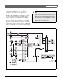
1
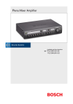
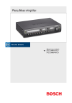
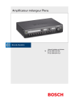
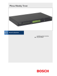
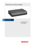
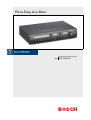
Plena Easy Line Mixer
Installation and User Instructions
en
PLE-10M2-EU
Plena Easy Line Mixer | Installation and User Instructions | Important safeguards
Important safeguards
Alerts on the apparatus
This symbol found on the apparatus indicates
hazards arising from dangerous voltages.
This symbol found on the apparatus indicates
the user should read all safety statements found
in the operating instructions.
This symbol found on the apparatus indicates
double insulation.
Warning
To reduce the risk of fire or electrical shock, do
not expose this apparatus to rain or moisture.
This symbol found on the apparatus indicates
that the apparatus must be placed in a separate
collection facility for electronic waste and not
disposed with household waste.
1 Read instructions - All the safety instructions for use
should be read before the system is operated.
2 Retain instructions - The safety instructions and
operating instructions should be retained for future
reference.
3 Heed warnings - All warnings on the unit and in the
operating instructions should be adhered to.
4 Follow instructions - All operating instructions and
instructions for use should be followed.
5 Cleaning - Unplug system units from the mains
outlet before cleaning. Do not use liquid cleaners or
aerosol cleaners. Use only a dry cloth for cleaning.
6 Attachments - Do not use attachments not
recommended by the product manufacturer as they
may cause hazards.
7 Water and Moisture - Do not use this unit near water,
for example near a bathtub, washbowl, kitchen sink,
or laundry basket, in a wet basement, near a
swimming pool, in an unprotected outdoor
installation or any area which is classified as a wet
location.
Bosch Security Systems | 2008-03 | PLE-10M2-EU en
en | 2
8 Accessories - Do not place this unit on an unstable
stand, tripod, bracket or mount. This unit may fall,
causing serious injury to a person and serious
damage to the unit. Use only a stand, tripod, bracket
or mount recommended by the manufacturer, or
sold with the product. Any mounting of the unit
should follow the manufacturer's instructions, and
should use a mounting accessory recommended by
the manufacturer. An appliance and cart
combination should be moved with care. Quick
stops, excessive force, and uneven surfaces may
cause the appliance and cart combination to
overturn.
9 Ventilation - Openings in the enclosure, if any, are
provided for ventilation and to ensure reliable
operation of the unit and to protect it from
overheating. These openings must not be blocked or
covered. The unit should not be placed in a built-in
installation unless proper ventilation is provided or
the manufacturer's instructions have been adhered
to. Maintain a minimum distance of 2 inch (50 mm)
around the front, the rear, and the sides of the unit
for sufficient ventilation.
10 Heat sources - Do not install the unit near any heat
sources such as radiators, stoves, or other apparatus
that produce heat (including amplifiers).
11 Open flames - No open flames, such as lighted
candles, should be placed on the unit.
12 Power sources - Units should be operated only from
the type of power source indicated on the marking
label. If you are not sure of the type of power supply
you plan to use, consult your appliance dealer or
local power company. For units intended to operate
from battery power, or other sources, refer to the
"Installation and User Instructions".
13 Grounding or polarisation - This unit may be
equipped with a polarised alternating current line
plug (a plug having one blade wider than the other).
This plug will fit into the power outlet only one way.
This is a safety feature. If you are unable to insert the
plug fully into the outlet, try reversing the plug. If the
plug still fails to fit, contact your electrician to
replace your obsolete outlet. Do not defeat the safety
purpose of the polarised plug. Alternatively, this unit
may be equipped with a 3-wire grounding type plug
having a third (grounding) pin. This plug will only fit
into a grounding-type power outlet. This is a safety
feature. If you are unable to insert the plug into the
Plena Easy Line Mixer | Installation and User Instructions | Important safeguards
14
15
16
17
18
19
20
outlet, contact your electrician to replace your
obsolete outlet. Do not defeat the safety purpose of
the grounding-type lug.
Power-Cord Protection - Power supply cords should
be routed so that they are not likely to be walked on
or pinched by items placed upon or against them,
paying particular attention to cords and plugs,
convenience receptacles, and the point where they
exit from the appliance.
Overloading - Do not overload outlets and extension
cords as this can result in a risk of fire or electrical
shock.
Object and Liquid Entry - Never push objects of any
kind into this unit through openings as they may
touch dangerous voltage points or short-out parts
that could result in a fire or electric shock. Never
spill liquid of any kind on the unit.
Servicing - Do not attempt to service this unit
yourself as opening or removing covers may expose
to dangerous voltage or other hazards. Refer all
servicing to qualified service personnel.
Damage Requiring Service - Unplug the unit from
the outlet and refer servicing to qualified service
personnel under the following conditions:
• When the power-supply cord or plug is damaged.
• If liquid has been spilled, or objects have fallen
into the unit.
• If the unit has been exposed to rain or water.
• If the unit does not operate normally by following
the instructions for use. Adjust only those
controls that are covered by the instructions for
use, as an improper adjustment of other controls
may result in damage and will often require
extensive work by a qualified technician to
restore the units to their normal operation.
• If the unit has been dropped or the unit has been
damaged.
• When the unit exhibits a distinct change in
performance; this indicates a need for service.
Replacement Parts - When replacement parts are
required be sure the service technician has used
replacement parts specified by the manufacturer or
parts which have the same characteristics as the
original part. Unauthorised substitutions may result
in fire, electric shock or other hazards.
Safety Check - Upon completion of any service or
repairs to the units, ask the service technician to
Bosch Security Systems | 2008-03 | PLE-10M2-EU en
en | 3
perform safety checks to determine that the unit is in
proper operating condition.
21 Lightning - For added protection of the units during
a lightning storm, or when it is left unattended and
unused for long periods of time, unplug it from the
wall outlet and disconnect the cable system. This will
prevent damage to the unit due to lightning and
power-line surges.
22 Disconnection - To completely disconnect this unit
from the AC mains, disconnect the power supply
cord plug from the AC receptacle. The mains plug of
the power supply cord shall remain readily operable
to be able to disconnect power from the unit.
23 Before installing or operating this product, always
read the Safety Instructions, which are available as a
separate document (9922 141 7014x). These
instructions are supplied together with all equipment
that can be connected to the mains.
Plena Easy Line Mixer | Installation and User Instructions | Important safeguards
en | 4
American Users
Canadian Users
Note
This equipment has been tested and found to
comply with the limits for a Class B digital
device, pursuant to part 15 of the FCC rules.
These limits are designed to provide reasonable
protection against harmful interference in a
residential installation.
This equipment generates, uses, and can
radiate radio frequency energy and, if not
installed and used in accordance with the
instructions, may cause harmful interference to
radio communications. However, there is no
guarantee that interference will not occur in a
particular installation. If this equipment does
cause harmful interference to radio or television
reception, which can be determined by turning
the equipment OFF and ON, the user is
encouraged to try to correct the interference by
one or more of the following measures:
• Reorient or relocate the receiving antenna.
• Increase the separation between the
equipment and the receiver.
• Connect the equipment into an outlet on a
circuit different from that to which the
receiver is connected.
• Consult the dealer or an experienced
radio/TV technician for help.
Note
This Class B digital device complies with
Canadian ICES-003.
Cet appareil numérique de classe B est
conforme à la norme NMB-003 du Canada.
Bosch Security Systems | 2008-03 | PLE-10M2-EU en
Thank you for choosing a Bosch Security Systems
product!
Plena Easy Line Mixer | Installation and User Instructions | Table of contents
en | 5
Table of contents
Important safeguards ...................................................................................................................................................2
Table of contents ...........................................................................................................................................................5
1. Introduction ....................................................................................................................................................................7
1.1 Purpose .....................................................................................................................................................................................7
1.2 Digital document .....................................................................................................................................................................7
1.3 Intended audience ..................................................................................................................................................................7
1.4 Related documentation ..........................................................................................................................................................7
1.5 Alerts ..........................................................................................................................................................................................7
1.6 Icons ...........................................................................................................................................................................................7
1.6.1 Note icons ...........................................................................................................................................................................7
1.6.2 Caution, Warning, and Danger icons ...........................................................................................................................7
1.7 Conversion tables ...................................................................................................................................................................8
2. Description .....................................................................................................................................................................9
2.1 The Plena product range .......................................................................................................................................................9
2.2 Contents of box .......................................................................................................................................................................9
2.3 The Plena Easy Line Mixer ....................................................................................................................................................9
2.4 Controls, connectors and indicators ............................................................................................................................... 11
2.4.1 Front panel ....................................................................................................................................................................... 11
2.4.2 Plena PLE-WP2Z3S wall panel .................................................................................................................................. 11
2.4.3 Rear panel ........................................................................................................................................................................ 12
3. Installation ................................................................................................................................................................... 15
3.1 Unpack unit ............................................................................................................................................................................ 15
3.2 Install unit in rack (optional) ............................................................................................................................................... 15
3.3 Check settings/connections .............................................................................................................................................. 15
3.4 Connect unit to mains ......................................................................................................................................................... 15
4. Connections and settings ........................................................................................................................................ 17
4.1 Connecting inputs ................................................................................................................................................................ 17
4.1.1 DC supply (battery) ........................................................................................................................................................ 17
4.1.2 Priority microphone (input 1) ....................................................................................................................................... 18
4.1.3 Secondary microphone (input 2) ................................................................................................................................ 19
4.1.4 Additional microphones (inputs 3 through 6) .......................................................................................................... 19
4.1.5 Emergency inputs ........................................................................................................................................................... 20
4.1.6 Music source inputs ....................................................................................................................................................... 22
4.2 Connecting outputs ............................................................................................................................................................. 23
4.2.1 Zone 1 and 2 ................................................................................................................................................................... 23
4.2.2 Call active contact .......................................................................................................................................................... 23
4.2.3 Master output .................................................................................................................................................................. 23
4.2.4 Line out/ loop through ................................................................................................................................................... 23
4.3 Unit settings .......................................................................................................................................................................... 24
4.3.1 Rear panel settings ........................................................................................................................................................ 24
4.3.2 Pin settings and labelling .............................................................................................................................................. 26
5. Operation ..................................................................................................................................................................... 27
5.1 Switch on and off ................................................................................................................................................................. 27
5.1.1 Switch on ......................................................................................................................................................................... 27
5.1.2 Switch off ......................................................................................................................................................................... 27
5.2 Microphone/line controls .................................................................................................................................................... 28
Bosch Security Systems | 2008-03 | PLE-10M2-EU en
Plena Easy Line Mixer | Installation and User Instructions | Table of contents
en | 6
5.3 Music controls ....................................................................................................................................................................... 28
5.3.1 Source selection ............................................................................................................................................................. 28
5.3.2 Volume control ................................................................................................................................................................ 28
5.4 Tone control .......................................................................................................................................................................... 28
5.4.1 Introduction ...................................................................................................................................................................... 28
5.4.2 Microphone/line tone control ....................................................................................................................................... 28
5.4.3 Music tone control .......................................................................................................................................................... 28
5.5 Output controls ..................................................................................................................................................................... 29
5.5.1 Zone selection ................................................................................................................................................................. 29
5.5.2 Master volume control ................................................................................................................................................... 29
6. Technical data ............................................................................................................................................................. 31
6.1 Electrical ................................................................................................................................................................................. 31
6.1.1 Mains power supply ....................................................................................................................................................... 31
6.1.2 Battery power supply ..................................................................................................................................................... 31
6.1.3 Performance .................................................................................................................................................................... 31
6.1.4 RJ-45 input 2 x ................................................................................................................................................................ 31
6.1.5 Mic/line input 6 x ............................................................................................................................................................. 31
6.1.6 Music inputs 3x ............................................................................................................................................................... 32
6.1.7 Emergency / telephone 1 x .......................................................................................................................................... 32
6.1.8 Loop through insert 1 x ................................................................................................................................................. 32
6.1.9 Master/music output 1 x ............................................................................................................................................... 32
6.1.10 Zone outputs 2 x ............................................................................................................................................................. 32
6.2 Mechanical ............................................................................................................................................................................. 32
6.3 Environmental ........................................................................................................................................................................ 32
Bosch Security Systems | 2008-03 | PLE-10M2-EU en
Plena Easy Line Mixer | Installation and User Instructions | Introduction
1
Introduction
1.1
Purpose
The purpose of these Installation and User Instructions
is to provide information required for installing,
configuring and operating a Plena Easy Line Mixer.
1.2
1.6
Icons
1.6.1
Note icons
The icons used in combination with Notes provide extra
information about the Note. See the following
examples:
Digital document
Note
General icon for notes.
These Installation and User Instructions are also
available as a digital document in the Adobe Portable
Document Format (PDF).
1.3
Intended audience
Note
Consult the indicated source of information.
These Installation and User Instructions are intended
for installers and users of a Plena system.
1.4
Related documentation
Safety Instructions (9922 141 1036x).
1.5
Alerts
Four types of alerts are used in this manual. The alert
type is closely related to the effect that may be caused if
it is not observed. These alerts - from least severe effect
to most severe effect - are:
• Note
Alert containing additional information. Usually, not
observing a note alert does not result in damage to
the equipment or personal injuries.
• Caution
The equipment can be damaged if the alert is not
observed.
• Warning
Persons can be (severely) injured, or the equipment
can be seriously damaged, if the alert is not
observed.
• Danger
Not observing the alert can result in death.
Bosch Security Systems | 2008-03 | PLE-10M2-EU en
en | 7
1.6.2
Caution, Warning, and Danger
icons
The icons used in combination with Caution, Warnings,
and Dangers indicate the type of hazard present. See the
following examples:
Caution, Warning, Danger
General icon for Cautions, Warnings and
Dangers.
Caution, Warning, Danger
Icon for risk of electric shock.
Caution, Warning, Danger
Icon for risk of electrostatic discharge.
Plena Easy Line Mixer | Installation and User Instructions | Introduction
1.7
Conversion tables
In this manual, SI units are used to express lengths,
masses, temperatures etc. These can be converted to
non-metric units using the following information.
table 1.1: Conversion of units of length
1 in =
25.4 mm
1 mm =
1 in =
2.54 cm
1 cm =
1 ft =
0.3048 m
1m=
1 mi =
1.609 km
1 km =
0.03937 in
0.3937 in
3.281 ft
0.622 mi
table 1.2: Conversion of units of mass
1 lb =
0.4536 kg
1 kg =
2,2046 lb
table 1.3: Conversion of units of pressure
1 psi =
68.95 hPa
1 hPa =
0.0145 psi
Note
1 hPa = 1 mbar.
table 1.4: Conversion of units of temperature
° F = 9 . ( ° C + 32)
° C = 5 . ( ° F 32)
°F= 5
°C= 9
Bosch Security Systems | 2008-03 | PLE-10M2-EU en
en | 8
Plena Easy Line Mixer | Installation and User Instructions | Description
2
Description
2.1
The Plena product range
The Plena Easy Line Mixer is part of the Plena product
range. Plena provides public address solutions for places
where people gather to work, worship, trade, or relax. It
is a family of system elements that are combined to
create public address systems tailored for virtually any
application.
The Plena product range includes:
• mixers
• preamplifiers
• power amplifiers
• a music source unit
• a digital message manager
• a feedback suppressor
• call stations
• an All-in-One system
• a voice alarm system
• a timer
• a charger
• a loop amplifier
The various elements are designed to complement each
other thanks to matched acoustical, electrical and
mechanical specifications.
2.2
Contents of box
The packaging box contains the following contents:
• PLE-10M2-EU
• Labels and colored pins for indicating favorite
settings
• Power cord
• Plena Bonus CD
• Mounting brackets (LBC 1901/00)
2.3
en | 9
The volume of each microphone/line signal can be
individually adjusted to obtain the required mix; the
mixed output is controlled via the master volume
control and separate high/low tone controls.
The unit is easy to use, and provides a crisp call or clear
music. The mixer also has enhanced features such as
ducking level control, priority, labelling, and setting
indicators.
All Microphone/line inputs can be switched between
microphone level and line level sensitivity. The inputs
are balanced but can also be used unbalanced. Phantom
power can be selected via a DIP switch to provide
power to condenser microphones. Input channels 1 and
2 can take priority over all other microphone and music
inputs:
• Input 1 can be activated by contact closure on a PTT
(push to talk). A chime can be configured to precede
an announcement.
• Input 2 can be switched automatically if a signal is
available at the input, for example, if someone
speaks into the microphone (VOX activation).
A telephone/100 V emergency input with VOX
activation is also provided for easy integration with
another PA system or a telephone paging system. It has
its own volume control and overrides all other inputs,
including the call station and inputs 1 and 2.
The unit also has a line output for generic use. This
output can be switched to music only, for example, so
that music on hold can be provided for the telephone
system. Loop through input and output connections
enable external sound processing equipment (for
example, an equalizer or Plena feedback suppressor) to
be connected between the preamplifier and the power
amplifier stages. A feedback suppressor can ensure
feedback-free, clear speech for all microphones.
The Plena Easy Line Mixer
The Plena Easy Line Mixer is a high performance,
professional public address unit for mixing up to six
separate microphone/line signals, and any one of three
separate music signals. For a schematic overview of the
Plena Easy Line Mixer, see figure 2.1 on the next page.
Bosch Security Systems | 2008-03 | PLE-10M2-EU en
Users can create custom labels for inputs, music sources,
and output zones. These labels can be attached to the
special holders at the front of the mixer. Colored pins
can also be inserted at various positions around the
volume and tone dial controls to indicate favorite
settings for a particular application.
Plena Easy Line Mixer | Installation and User Instructions | Description
An LED meter monitors the master output before the
zone selection. This signal is also present on the
headphone connector below the output meter.
The Plena Easy Line Mixer has an input for 24 VDC
backup power, but has no built in 24 VDC battery
charger. However, Power Amplifiers from the Plena
product range have a built in 24 VDC battery charger.
A separate battery charger is, therefore, not required.
The charger charges the battery with a 0.5 A constant
current until the battery voltage reaches 27.4 VDC. The
charger then switches over to constant voltage charging
(also known as float charging).
figure 2.1: Schematic overview of the Plena Easy Line Mixer
Bosch Security Systems | 2008-03 | PLE-10M2-EU en
en | 10
Note
When using the unit with backup power of 24 V,
make sure that the unit is always powered ON.
When the unit is switched OFF, the batteries will
be drained as this will be regarded as a power
source. Consequently the unit will revert to 24
VDC power from the 24 V input.
Plena Easy Line Mixer | Installation and User Instructions | Description
2.4
Controls, connectors and
indicators
2.4.1
Front panel
16 Air inlet holes.
See figure 2.2 for an overview of the controls and
indicators.
1 Power button.
2 Label holder for user-defined description of
microphone/line inputs - custom labels can be
created by user.
3 Master high tone control for microphone/line inputs.
4 Label holder for user-defined description of music
sources - custom labels can be created by user.
5 Master high tone control for music inputs.
6 Label holder for user-defined description of zone
names - custom labels can be created by user.
7 Master volume control - controls all inputs except
emergency and call station.
8 Output level meter (-18 db, 0 db)
9 Input level control:
• microphone/line 1
• microphone/line 2
• microphone/line 3
• microphone/line 4
• microphone/line 5
• microphone/line 6
10 Master low tone control for microphone/line inputs.
11 Music source selector (for music inputs 1, 2, and 3).
12 Music source volume control.
13 Master low tone control for music inputs.
14 Zone 1 selection button.
15 Zone 2 selection button
1
2
en | 11
Note
Do not obstruct the airflow into the unit.
17 Headphone socket.
Note
Users can create custom labels for the:
microphone/line inputs, description of the music
sources, and audio output zones 1 and 2. These
labels can be attached to the mixer at position
numbers 2, 4, and 6 (see figure 2.2). Colored
pins can also be inserted at various positions
around the dial controls to indicate the favorite
settings for a particular application. For more
information on inserting and removing pins, see
section 4.3.2.
2.4.2
Plena PLE-WP2Z3S wall panel
The optional Plena PLE-WP2Z3S wall panel can be
used to remotely control the unit from a maximum of
four remote locations. The appearance of the wall panel
is matched to the Bosch loudspeaker volume controls.
The zone can be activated or deactivated, and the music
source can be easily changed. The status of each zone
and music source is indicated by an LED.
A standard CAT 5 cable is used to connect the wall
panel to the mixer. The maximum distance is 200 m.
Please refer to the relevant datasheet for more
information.
3
4
5
6
7
8
B
9
10
figure 2.2: Front panel
Bosch Security Systems | 2008-03 | PLE-10M2-EU en
11
12
13
14
15
16
17
Plena Easy Line Mixer | Installation and User Instructions | Description
2.4.3
Rear panel
See figure 2.3 for an overview of the connectors and
switches:
1 Microphone/line 1 input with trigger, Euro style
pluggable screw terminal connector - DIP switch
settings for: chime, PTT (push to talk), mic/line,
speech filter, and phantom power (see number 3).
Input is wired in parallel with microphone/line 1,
XLR connector (see number 2).
2 Microphone/line 1 input, XLR connector - DIP
switch settings for: chime, PTT (push to talk),
mic/line, speech filter, and phantom power (see
number 3). Input is wired in parallel with
microphone/line 1, Euro style pluggable screw
terminal connector (see number 1).
3 DIP switch for microphone/line 1 and microphone/
line 2 (see numbers 1 and 2, and 4 respectively).
4 Microphone/line 2 input, XLR connector - DIP
switch settings for speech filter, mic/line, VOX, and
phantom power (see number 3).
5 Microphone/line 3 input, XLR connector - DIP
switch settings for mic/line, and phantom power
(see number 6).
6 DIP switch for microphone/line 3 and microphone/
line 4 (see numbers 5 and 7 respectively).
7 Microphone/line 4 input, XLR connector - DIP
switch settings for mic/line, and phantom power
(see number 6).
8 Microphone/line 5 input, XLR connector - DIP
switch settings for mic/line, and phantom power
(see number 9).
9 DIP switch for microphone/line 5 and microphone/
line 6 (see numbers 8 and 10 respectively).
10 Microphone/line 6 input, XLR connector - DIP
switch settings for mic/line, and phantom power
(see number 9).
11 Mains voltage switch, C13 - 115/230
VAC 50/60 Hz.
12 Tel. emergency/100V input, Euro style pluggable
screw terminal connector - VOX function. This input
has highest priority.
13 Telephone emergency/100V input volume control control range -25 dB to 0dB (see number 12).
14 Chime volume control for microphone/line input 1
(see numbers 1 and 2).
15 Ducking level control for microphone/line inputs 1
and 2.
Bosch Security Systems | 2008-03 | PLE-10M2-EU en
en | 12
16 Call station input, RJ-45 connector - PLE-2CS or
PLE-2CSMM, chimes are in call station. This input
has second highest priority.
17 Remote control wall-panel-input, RJ-45 connector.
Wall panel incorporates: BGM source selection, and
zone on/off control.
18 Music input (number 1 disc), 2x RCA/cinch
connectors. Stereo, summed mono.
19 Music input (number 2 radio), 2x RCA/cinch
connectors. Stereo, summed mono.
20 Music input (number 3 auxiliary), 2x RCA/cinch
connectors. Stereo, summed mono.
21 Pre-out, amp in insert, 2x RCA/cinch connector can be used for EQ or feedback suppressor.
22 Master switch for line out or music (see number 23).
23 Music master output, XLR connector - switch setting
for line out, or music only (see number 22).
24 Volume override output and 24 VDC input:
• Volume override output - Euro style pluggable screw
terminal connector.
• 24 VDC backup power input - Euro style pluggable
screw terminal connector.
25 Zone 1 output, XLR connector, balanced.
26 Zone 2 output, XLR connector, balanced.
27 Mains fuse.
28 Earth connection screw.
Note
The unit must be earthed.
29 Mains connector (3-pole).
Plena Easy Line Mixer | Installation and User Instructions | Description
3
4
5
6
Gnd
8
Mic
Line
Phantom Off
Mic
Line
Chime
PTT
Mic
Flat
Phantom
Vox
Mic
Flat
Call
Trigger
7
9
10
Mic
Line
Phantom Off
Mic
Line
2
Off
Off
Line
Speech
Off
Off
Line
Speech
1
en | 13
11
PLE-10M2-EU
F01U.066.938
8900 192 21001
2 Channel Mixer
115/230V~, 50/60Hz
S/N
Rated input
power : 40VA
Line fuse
T1L250V for 230V
T1.6L250V for 115V
Design & Quality
The Netherlands
Apparatus delivered
connected for 230V~
PLE-2CS
Telephone/Emergency Input
100V
Chime
In
Ducking
Line Music
Out Only
0 Gnd
Mix
Mute
Wall Panel
12
13 14 1516 17
1(disc)
2(radio)
3(aux)
Out
Insert
18 19 20 21 22
figure 2.3: Rear panel
Bosch Security Systems | 2008-03 | PLE-10M2-EU en
Output
23
24
Zone 1 Out
Zone 2 Out
25
26
27 28 29
Plena Easy Line Mixer | Installation and User Instructions | Description
Intentionally left blank
Bosch Security Systems | 2008-03 | PLE-10M2-EU en
en | 14
Plena Easy Line Mixer | Installation and User Instructions | Installation
3
3.1
Installation
3.3
Unpack unit
1 Connect any additional equipment (see section 4.1
and 4.2).
2 Check the settings (see section 4.3).
1 Remove the unit from the box, and discard the
packaging material according to local regulations.
2 Use your fingernails to carefully peel off the
protective plastic film from the label holders. Do not
use sharp or pointed objects.
3.2
en | 15
Install unit in rack (optional)
The Plena Easy Line Mixer is intended for tabletop use,
but you can also mount the unit in a 19" rack (see
figure 3.1).
If you mount the unit in a rack, you must:
• ensure that it does not exceed the overheating
temperature (55 °C ambient).
• use the included Bosch mounting brackets
(LBC 1901/00).
• remove the 4 feet from the bottom of the unit.
3.4
Check settings/connections
Connect unit to mains
Caution
Potential equipment damage. Before
connecting power, always check the voltage
selector on the rear panel of the unit.
1 Make sure the voltage selector (115V/ 230V) is
correctly set for the country’s main voltage
(see figure 3.2).
2 Make sure the power switch on the front of the unit
is set to Off.
3 Connect the power cord to the mains connector and
plug it into the mains outlet.
1
B
figure 3.1: Installing the unit in a rack
figure 3.2: Power connection and voltage selector
Bosch Security Systems | 2008-03 | PLE-10M2-EU en
Plena Easy Line Mixer | Installation and User Instructions | Installation
Intentionally left blank
Bosch Security Systems | 2008-03 | PLE-10M2-EU en
en | 16
Plena Easy Line Mixer | Installation and User Instructions | Connections and settings
4
Connections and settings
4.1
Connecting inputs
4.1.1
DC supply (battery)
The Plena Easy Line Mixer has as a built in charger,
which charges the connected battery (or batteries if
connected in series). A separate battery charger is,
therefore, not required. The charger charges the battery
with a 0.5 A constant current until the battery voltage
reaches 27.4 VDC. The charger then switches over to
constant voltage charging (also known as float charging).
This means that a battery can be charged at the same
rate it is discharging, and thus full capacity battery can
be assured.
Caution
The connection cable must have an in-line fuse.
Use the type of fuse shown in the following
figure.
This type of charging is suited for low duty-cycle
applications where a relatively high current or power is
infrequently required.
Caution
Make sure the unit is earthed.
The Plena Easy Line Mixer has a 24 VDC input
(terminal screw). This input can be used in mobile
applications, such as boats where 120 or 230 VAC is not
available or in applications that must continue to
operate in case of a power failure.
When a 24 VDC battery is connected (typically
consisting of two 12 VDC lead-acid batteries in series),
the unit will operate on the supplied DC voltage.
12 V
D
FUS
+
C
12 V
D
C
figure 4.1: Connecting a DC power supply
Bosch Security Systems | 2008-03 | PLE-10M2-EU en
Note
If the backup power system has to comply to the
EN54-4 standard or similar standards for
backup power and charging speeds, Bosch
recommends the PLN-24CH10. The PLN24CH10 is a dedicated battery charger and
power supply that is fully EN54-4 compliant.
Note
If battery charging is not required, the 0.5 A
maximum output current can be used for volume
overrides or other purposes instead.
+
-
en | 17
E
Plena Easy Line Mixer | Installation and User Instructions | Connections and settings
4.1.2
Priority microphone (input 1)
The priority microphone (or a generic call station) that
can be used with push to talk (PTT) should be
connected to “microphone/line 1 input”. The PTT
mode can be activated by setting the DIP switch (3) at
the rear of the unit. Microphone/line 1 input has
priority over all other microphone/line inputs.
If, however, the “Tel. emergency/100V input” receives a
signal, all inputs including microphone/line 1 input will
be overruled.
The microphone/line 1 input has two connectors wired
in parallel:
• an XLR connector (for a 3 pole microphone), and
• a Euro style pluggable screw terminal connector.
figure 4.2: XLR connector only
The Euro style pluggable screw terminal connector has
a trigger input, which can be used in combination with
the Euro and XLR connector.
The priority microphone can be connected to the
microphone/line 1 input as follows:
• XLR connector only. See figure 4.2.
• XLR connector with trigger. See figure 4.3.
• Euro connector with trigger. See figure 4.4.
• Euro connector only (without trigger).
figure 4.3: XLR connector with trigger
Note
If a microphone is connected to both the
XLR connector and the Euro connector for the
microphone/line 1 input, the input signals will be
added together.
Set the DIP switch settings next to the XLR connector
for microphone/line 1, as required. See section 4.3.
Note
When connecting an unbalanced line level
(200 mV) signal to the microphone/line input,
connect it as follows: Signal to pin 2, pin 1 and
pin 3 to ground.
Bosch Security Systems | 2008-03 | PLE-10M2-EU en
figure 4.4: Euro connector with trigger
en | 18
Plena Easy Line Mixer | Installation and User Instructions | Connections and settings
4.1.3
Secondary microphone (input 2)
Connect a secondary microphone to “microphone/line
input 2”. See figure 4.5.
Microphone/line input 2 has a DIP switch (3) at the rear
of the unit for setting the VOX mode. If the DIP switch
is set to VOX, the microphone/line input will
automatically be switched when a signal is sensed at the
microphone/line 2 input. For example, when someone
speaks into the microphone, other sound will either be
muted or ducked, depending on the setting of the
ducking level control at the rear of the unit. See
section 4.3.
The Tel. emergency/100V input, Call station input, and
Microphone/line input 1 all have priority over the
Microphone/line input 2. Therefore, any signal received
on any one of these inputs will always be heard
regardless of the ducking level control setting for
Microphone/line input 2.
Set the DIP switch settings next to the XLR connector
as required. See section 4.3.
figure 4.5: Connecting microphone inputs
Bosch Security Systems | 2008-03 | PLE-10M2-EU en
4.1.4
en | 19
Additional microphones
(inputs 3 through 6)
Connect additional microphones to microphone/line
inputs 3 through 6, as required. See figure 4.5. These
microphones will mix with the background music.
Set the DIP switch settings next to the XLR connector
for microphone/lines 3 through 6, as required. See
section 4.3.
Plena Easy Line Mixer | Installation and User Instructions | Connections and settings
4.1.5
Emergency inputs
The Tel. emergency/100V input, with VOX
functionality, is used for receiving emergency
announcements or signals (such as a fire alarm). This
input has absolute priority, and will overrule all inputs
when an emergency announcement or signal is
received.
Either a telephone line or a 100 V input signal can be
connected to the Euro style pluggable screw terminal
connector (12) at the rear of the unit. See section 4.1.5.1
and section 4.1.5.2.
Caution
Never connect telephone lines and a 100 V
signal to the Euro style connector at the same
time.
To adjust the volume of the emergency announcement
or signal, turn the rotary dial (13) at the rear of the unit.
For safety reasons, the volume of the emergency
announcement or signal cannot be set to zero.
figure 4.6: Connecting 100 Volt input signal
Bosch Security Systems | 2008-03 | PLE-10M2-EU en
en | 20
The master volume control setting (7) does not influence
the volume setting of the emergency announcement or
signal.
Note
The Tel. emergency/100V input is muted when
not active.
4.1.5.1
Connecting 100 Volt input signal
Connect the 100 Volt input signal as shown in
figure 4.6.
Plena Easy Line Mixer | Installation and User Instructions | Connections and settings
4.1.5.2
Connecting telephone lines
Connect the telephone lines as shown in figure 4.7.
Caution
A connection to a telephone network must
always be made via a telephone coupler that
provides adequate isolation between the
telephone network (PBX) and the Plena system.
The telephone coupler must also meet all
relevant requirements for this type of
communication equipment as imposed by law
and/or responsible telecommunication
organizations in the country of use. Never try to
make a direct connection between the telephone
network and the mixer.
figure 4.7: Connecting emergency telephone lines
Bosch Security Systems | 2008-03 | PLE-10M2-EU en
en | 21
Plena Easy Line Mixer | Installation and User Instructions | Connections and settings
4.1.6
Music source inputs
When using a CD player, tuner or other auxiliary
device for background music, connect the line-out
connectors of the music source to the appropriate line-in
connectors of the mixer.
figure 4.8: Connecting music source inputs
Bosch Security Systems | 2008-03 | PLE-10M2-EU en
en | 22
Plena Easy Line Mixer | Installation and User Instructions | Connections and settings
4.2
Connecting outputs
4.2.1
Zone 1 and 2
Connect a power amplifier to the Zone 1 and 2 XLR
connectors (25 and 26 ) at the rear of the unit.
4.2.2
4.2.3
en | 23
Master output
Use the music master output connector (23) to provide a
dedicated music out source for another device. For
example, the music master output can be connected to a
telephone coupler, so that callers can listen to music
when they are put on hold (see figure 4.9).
Call active contact
The call active contact is closed when a call is active.
To select the dedicated music out source, set the master
switch for “line out or music only” (22) to “music only”.
Only the music inputs (18, 19, and 20) will be audible.
All other inputs, including the Tel. emergency/100V
input will not be sent to this output.
To hear all mixed inputs (microphone/line, emergency,
and music) set the master switch for “line out or music
only” (22) to “line out”.
4.2.4
Line out/ loop through
Use the Pre-out, amp in insert (21) external sound
processing equipment (e.g. an equalizer or Plena
feedback suppressor) to be connected between the
preamplifier and the power amplifier stages.
See figure 4.9.
figure 4.9: Connecting music source inputs
Bosch Security Systems | 2008-03 | PLE-10M2-EU en
Plena Easy Line Mixer | Installation and User Instructions | Connections and settings
4.3
Unit settings
4.3.1
Rear panel settings
en | 24
The unit can be quickly set-up for operation by setting
the following controls at the rear of the unit:
• DIP switches
• Rotary dials
• Master switch for line out or music only.
See the following tables for an overview of the settings
and typical examples of their use.
table 4.1: DIP switch settings
DIP switch
On
Chime will be sounded at the
Chime
(mic/line 1)
beginning of an announcement.
PTT “Push to talk”
(mic/line 1 only)
Line
Speech filter
Phantom power
VOX
(mic/line 2 only)
This input is muted when the push
to talk contact is open. When the
push to talk contact is closed:
• this input is available for
speech.
• a chime will sound, if selected.
• the music and other mic/line
inputs will be reduced in
volume to the level set by the
ducking level control knob.
Input signal from line.
Enhances clarity of speech, by
cutting-off the lower frequencies
of the signal.
Provides power to condenser
microphones.
Temporarily suppresses the
background music to an
adjustable “ducking level”
(see table 4.2) while you speak
into the microphone.
The VOX mode is normally used
with hand-held microphones such
as the LBC 2900/15. Background
music and announcements will be
heard in the selected zones.
A chime is not available in this
mode.
Bosch Security Systems | 2008-03 | PLE-10M2-EU en
Off
Chime will not be sounded
at the beginning of an
announcement.
Push to talk off. The signal
will be mixed with the other
mic/line signals.
Microphone 1 will mix with
the background music or
the other microphones in
the selected zones.
Typical example (On)
Announcement of train
departure time.
Input signal from
microphone.
Speech filter inactive.
Depends on set-up.
Phantom power
unavailable.
Enable phantom power if
you use electret or
condenser microphones.
Use to make casual
announcements (such as
announcing the winner of
a competition) while
temporarily suppressing
the background music to
an adjustable ducking
level.
VOX inactive.
Microphone 2 will mix with
the background music or
the other microphones in
the selected zones.
Users can have private
conversations during live
broadcasts (for example,
with an all call callstation, such as the
PLE-1CS).
Use for announcements
Plena Easy Line Mixer | Installation and User Instructions | Connections and settings
table 4.2: Rotary controls
Rotary control
Effect
Ducking level control Sets the required ducking level when VOX and/or
push to talk is active (see table 4.1). When the
ducking level is set to mute, the music volume will be
fully attenuated; when the ducking level is set to mix,
both music and speech inputs can be heard - music
and speech will be mixed. When ducking the music
input is ducked (attenuated), the microphone/line
inputs are always muted when a call is made.
Chime volume
Alters the chime volume. The mid range is -8 dB
control
(40 V), which should be sufficient for most
applications. Test the chime by switching on
microphone 1. Remove the microphone after testing
if it is not further required.
Telephone
Attenuates the emergency announcement or signal.
emergency/100V
Control range from -25 dB to 0 dB. For safety
volume control
reasons, the volume of the emergency
announcement or signal cannot be fully set to zero.
en | 25
Typical example
Set the ducking level control to
mute if you want the
announcement to be heard without
background music.
Set the volume of the chime to a
higher level when the system is
being used in large open areas or
when important announcements
have to made.
Set the volume of the emergency
announcement to a higher level
when the system is being used in
large open areas.
Note
When PTT or VOX are selected, the ducking
control controls between 3 dB attenuation (very
little ducking) to –∞ dB (muted).
table 4.3: Master switch for line out or music only
Slide switch setting Effect
Line out
All mixed inputs (microphone/line, emergency, and
music) are available.
Music only
A dedicated music out source is available for another
external device. Only the music inputs (18, 19, and
20) are available. All other inputs, including the
Tel. emergency/100V input will be overridden.
Bosch Security Systems | 2008-03 | PLE-10M2-EU en
Typical example
Various set-ups are possible.
The “music master output” can be
connected to a telephone system,
so that callers can listen to music
when they are put on hold.
Plena Easy Line Mixer | Installation and User Instructions | Connections and settings
4.3.2
Pin settings and labelling
Users can create custom labels for the: microphone/line
inputs, description of the music sources, and audio
output zones 1 and 2. These labels can be attached to
the mixer at position numbers 2, 4, and 6 (see
figure 2.2). Colored pins can also be inserted at various
positions around the dial controls to indicate the favorite
settings for a particular application.
The pins are engineered in such a way that they cannot
be taken out by hand. This is to prevent tampering. The
pins are intended to be inserted once, during installation
of the unit. The silver pins should be used to indicate
the preferred settings of the unit. The red pins can
optionally be used to indicate the maximum setting of a
knob.
If these settings have to be changed, use a pair of softtipped pliers to carefully remove the pins. If you do not
have a pair of soft-tipped pliers, you can use ordinary
pliers instead, but first place some plastic tape on the
tips of the pliers to prevent damaging the front of the
unit.
To remove the clear plastic covers in front of the labels:
1 Carefully insert a small screwdriver into the cut-out
at the bottom of the plastic cover.
2 Gently lift the cover, and bend it in the middle. Take
care not to force the cover or the front panel.
To reattach the plastic covers with paper labels:
1 Insert the paper label into the holder at the front of
the unit.
2 Pick up the cover, and then bend it slightly in the
middle by hand.
3 Fit the cover into the slot at the front of the unit, and
then gently release the cover, making sure that the
paper label stays in place.
Bosch Security Systems | 2008-03 | PLE-10M2-EU en
en | 26
Plena Easy Line Mixer | Installation and User Instructions | Operation
5
Operation
5.1.2
en | 27
Switch off
Set the power button (1) on the front of the unit to Off popped out (see figure 5.2).
5.1
Switch on and off
5.1.1
Switch on
Caution
Potential equipment damage. Before applying
power, always check the voltage selector at the
rear of the unit.
1 Make sure the voltage selector (115V/ 230V) is
correctly set for the country’s main voltage (see
figure 5.1).
2 Set the power button (1) on the front of the unit to
On - pushed in (see figure 5.2).
figure 5.1: Voltage selector
Bosch Security Systems | 2008-03 | PLE-10M2-EU en
Plena Easy Line Mixer | Installation and User Instructions | Operation
5.2
Microphone/line controls
Use the volume controls (9) to individually control the
sound level of microphone/line inputs 1 through 6.
Note
Users can create custom labels for the:
microphone/line inputs, description of the music
sources, and audio output zones 1 and 2. These
labels can be attached to the mixer at position
numbers 2, 4, and 6 (see figure 5.2). Colored
pins can also be inserted at various positions
around the dial controls to indicate the favorite
settings for a particular application.
en | 28
The tone controls are not standard bass and treble
controls: they can be used as a traditional tone control
with high and low control, but also have a powerful
contour that addresses problems found in real situations.
5.4.2
Microphone/line tone control
The tone control for the microphone and line inputs
boosts warmth in voices without boosting rumble, and
cuts rumble without loosing warmth in the low
frequencies. In the high frequencies, the tone control
boosts sparkle without adding sharpness, but when
cutting is first, cuts harshness and sharpness without
reducing clarity.
5.3
Music controls
Use the Hi (high) and Lo (low) tone controls (see
figure 5.2, numbers 3 and 10) to collectively change the
tone of microphone/line inputs 1 through 6.
5.3.1
Source selection
5.4.3
Use the music source selector (11) to select one of the
connected music sources.
5.3.2
Volume control
Use the music source volume control (12) to control the
sound level of the selected music source.
5.4
Tone control
5.4.1
Introduction
The unique tone controls provide separate control for
mic/line inputs and music inputs so that the voice on
the microphones can be specifically optimized for
excellent speech or singing. Correspondingly, the tone
controls for background music provide the most
appropriate music reproduction.
1
2
Music tone control
The tone control for the music inputs boosts deep bass
first without making the sound boomy, and cuts rumble
without loosing warmth in the low frequencies. In the
high frequencies, the tone control is similar to the
microphone inputs, with slightly different frequencies to
suit music reproduction.
Use the Hi (high) and Lo (low) tone controls (see
figure 5.2, numbers 5 and 13) to change the tone of the
selected music source.
3
4
5
6
7
8
B
9
10
figure 5.2: Front panel
Bosch Security Systems | 2008-03 | PLE-10M2-EU en
11
12
13
14
15
16
17
Plena Easy Line Mixer | Installation and User Instructions | Operation
5.5
Output controls
5.5.1
Zone selection
Use the zone selection buttons (14 and 15) to route the
music/microphone, line mix from the mixer output to
loudspeaker zone 1 and/or loudspeaker zone 2.
Announcements, however, are always routed to both
zones, irrespective of the position of the zone selection
buttons.
5.5.2
Master volume control
Use the master volume control dial (7) to collectively
control the sound level of all outputs, except the
emergency announcement/signal.
Bosch Security Systems | 2008-03 | PLE-10M2-EU en
en | 29
Plena Easy Line Mixer | Installation and User Instructions | Operation
Intentionally left blank
Bosch Security Systems | 2008-03 | PLE-10M2-EU en
en | 30
Plena Easy Line Mixer | Installation and User Instructions | Technical data
6
Technical data
6.1
Electrical
6.1.1
Mains power supply
Voltage
115/230 VAC, ±10%, 50/60 Hz
Power consumption
25 VA
6.1.2
Battery power supply
Voltage
24 VDC, ±15%
Current
6A
Charge current
0.5 ADC
Charge float voltage
27.4 VDC
6.1.3
Performance
Frequency response
50 Hz to 20 kHz (+1/-3 dB)
Low Control
Max -12/+12 dB (frequency is level dependent)
Hi Control
Max -12/+12 dB (frequency is level dependent)
6.1.4
RJ-45 input 2 x
Call station input
For PLE-2CS(MM)
Wall panel input
For PLE-WP3S2Z
Bosch Security Systems | 2008-03 | PLE-10M2-EU en
6.1.5
Mic/line input 6 x
Input 1 (Push-to-talk contact with ducking
functionality)
5-pin Euro style, balanced, phantom
3-pin XLR, balanced, phantom
Input 2-6 (VOX with ducking functionality on
input 2)
3-pin XLR, balanced, phantom
Sensitivity
1 mV (mic); 200 mV (line)
Impedance
>1 kohm (mic); >5 kohm (line)
Dynamic range
100 dB
S/N (flat at max volume)
>63 dB (mic); >70 dB (line)
S/N (flat at min volume/muted)
>75 dB
CMRR
>40 dB (50 Hz to 20 kHz)
Headroom
>10 dB
Speech filter
-3 dB @ 315 Hz, high-pass, 6 dB/oct
Phantom power supply
16 V via 1.2 kohm (mic)
Speech filter
-3 dB @ 315 Hz, high-pass,
6 dB/oct
VOX (input 1 & 2)
attack time 150 ms; release time 2 s
en | 31
Plena Easy Line Mixer | Installation and User Instructions | Technical data
6.1.6
Music inputs 3x
Connector
Cinch, stereo converted to mono
Sensitivity
200 mV
Impedance
22 kohm
S/N (flat at max volume)
>70 dB
S/N (flat at min volume/muted)
>75 dB
Headroom
>25 dB
6.1.7
Emergency / telephone 1 x
Connector
7-pin, Euro style pluggable screw terminal
Sensitivity tel
100 mV – 1 V adjustable
Sensitivity 100V
10 V – 100 V adjustable
Impedance
>10 kohm
S/N (flat at max volume)
>65 dB
VOX
threshold 50 mV; attack time 150 ms; release time 2 s
6.1.8
Loop through insert 1 x
Connector
Cinch
Nominal level
1V
Impedance
>10 kohm
6.1.9
Master/music output 1 x
Connector
3-pin XLR, balanced
Nominal level
1V
Impedance
<100 ohm
Bosch Security Systems | 2008-03 | PLE-10M2-EU en
6.1.10 Zone outputs 2 x
Connector
3-pin XLR, balanced
Nominal level
1V
Impedance
<100 ohm
6.2
Mechanical
Dimensions (H x W x D)
100 x 430 x 270 mm (19" wide, 2U high)
Mounting
Stand-alone, 19" rack
Color
Charcoal
Weight
Approx. 10.5 kg
6.3
Environmental
Operating temperature
-10 to +55 ºC
Storage temperature
-40 to +70 ºC
Relative humidity
<95%
en | 32
For more information visit
www.boschsecuritysystems.com
© Bosch Security Systems B.V.
Data subject to change without notice
2008-03 | PLE-10M2-EU en