1
Cat. No.
I52E-EN-04
Trajexia motion control system
programming manual
TJ1-MC04
TJ1-MC16
Trajexia motion control system
Cat. No.
I52E-EN-05
programming manual
Omron Europe B.V. Wegalaan 67-69, NL-2132 JD, Hoofddorp, The Netherlands. Tel: +31 (0) 23 568 13 00 Fax: +31 (0) 23 568 13 88 www.omron-industrial.com
Middle East & Africa
Tel: +31 (0) 23 568 11 00
www.omron-industrial.com
Finland
Tel: +358 (0) 207 464 200
www.omron.fi
Italy
Tel: +39 02 326 81
www.omron.it
Denmark
Tel: +45 43 44 00 11
www.omron.dk
Hungary
Tel: +36 1 399 30 50
www.omron.hu
Czech Republic
Tel: +420 234 602 602
www.omron-industrial.cz
Germany
Tel: +49 (0) 2173 680 00
www.omron.de
Belgium
Tel: +32 (0) 2 466 24 80
www.omron.be
France
Tel: +33 (0) 1 56 63 70 00
www.omron.fr
Austria
Tel: +43 (0) 2236 377 800
www.omron.at
Netherlands
Tel: +31 (0) 23 568 11 00
www.omron.nl
Spain
Tel: +34 913 777 900
www.omron.es
Norway
Tel: +47 (0) 22 65 75 00
www.omron.no
Sweden
Tel: +46 (0) 8 632 35 00
www.omron.se
Poland
Tel: +48 (0) 22 645 78 60
www.omron.pl
Switzerland
Tel: +41 (0) 41 748 13 13
www.omron.ch
Portugal
Tel: +351 21 942 94 00
www.omron.pt
Turkey
Tel: +90 216 474 00 40
www.omron.com.tr
Russia
Tel: +7 495 648 94 50
www.omron-industrial.ru
United Kingdom
Tel: +44 (0) 870 752 08 61
www.omron.co.uk
Authorised Distributor:
Note:
Although we do strive for perfection, Omron Europe BV and/or its subsidiary and affiliated companies do not warrant or make any representations regarding the correctness or completeness
of information described in this catalogue. Product information in this catalogue is provided ‚as is‘ without warranty of any kind, either express or implied, including, but not limited to, the
implied warranties of merchantability, fitness for a particular purpose, or non-infringement. In a jurisdiction where the exclusion of implied warranties is not valid, the exclusion shall be
deemed to be replaced by such valid exclusion, which most closely matches the intent and purpose of the original exclusion. Omron Europe BV and/or its subsidiary and affiliated companies
reserve the right to make any changes to the products, their specifications, data at its sole discretion at any time without prior notice. The material contained in this catalogue may be out of
date and Omron Europe BV and/or its subsidiary and affiliated companies make no commitment to update such material.
Cat. No. I52E-EN-04
Notice
/i
OMRON products are manufactured for use according to proper procedures
by a qualified operator and only for the purposes described in this manual.
The following conventions are used to indicate and classify precautions in
this manual. Always heed the information provided with them. Failure to
heed precautions can result in injury to people or damage to property.
Definition of precautionary information
WARNING
Indicates a potentially hazardous situation, which, if not avoided,
could result in death or serious injury.
Caution
Indicates a potentially hazardous situation, which, if not avoided,
may result in minor or moderate injury, or property damage.
Trademarks and Copyrights
PROFIBUS is a registered trademark of PROFIBUS International.
MECHATROLINK is a registered trademark of Yaskawa Corporation.
DeviceNet is a registered trademark of Open DeviceNet Vendor Assoc INC.
CIP is a registered trademark of Open DeviceNet Vendor Assoc INC.
CANopen is a registered trademark of CAN in Automation (CiA).
ModbusTCP is a registered trademark of Modbus IDA.
Trajexia is a registered trademark of OMRON.
Motion Perfect is a registered trademark of Trio Motion Technology Ltd.
All other product names, company names, logos or other designations
mentioned herein are trademarks of their respective owners.
Revision 5.0
PROGRAMMING MANUAL
© OMRON, 2010
All rights reserved. No part of this publication may be reproduced, stored in a retrieval system, or transmitted, in any form, or by any means, mechanical, electronic, photocopying,
recording, or otherwise, without the prior written permission of OMRON.
No patent liability is assumed with respect to the use of the information contained herein.
Moreover, because OMRON is constantly striving to improve its high-quality products, the
information contained in this manual is subject to change without notice. Every precaution
has been taken in the preparation of this manual. Nevertheless, OMRON assumes no
responsibility for errors or omissions. Neither is any liability assumed for damages resulting
from the use of the information contained in this publication.
I
About this manual
This manual describes the installation and operation of the Trajexia Motion
Control System.
Please read this manual and the related manuals listed in the following table
carefully and be sure you understand the information provided before
attempting to install or operate the Trajexia Motion Control units. Be sure to
read the precautions provided in the following section.
/i
Revision 5.0
Name
Cat. No.
Contents
Trajexia motion control system
QUICK START
GUIDE
I50E
Describes how to get quickly familiar
with Trajexia, moving a single axis using
MECHATROLINK-II, in a test set-up.
Trajexia motion control system HARDWARE
REFERENCE MANUAL
I51E
Describes the installation and hardware
specification of the Trajexia units, and
explains the Trajexia system philosophy.
Trajexia motion control system
PROGRAMMING
MANUAL
I52E
Sigma-II Servo
Driver manual
SIEP S800000 15
Describes the installation and operation
of Sigma-II Servo Drivers
Sigma-III with
MECHATROLINK
interface manual
SIEP S800000 11
Describes the installation and operation
of Sigma-III Servo Drivers with MECHATROLINK-II interface
Sigma-V Servo
Driver manual
SIEP S800000-44-O-OY
SIEP S800000-46-O-OY
SIEP S800000-48-O-OY
Describes the installation and operation
of Sigma-V Servo Drivers
JUNMA series servo
drive manual
TOEP-C71080603 01-OY Describes the installation and operation
of JUNMA Servo Drivers
PROGRAMMING MANUAL
Describes the BASIC commands to be
used for programming Trajexia, communication protocols and Trajexia Studio
software, gives practical examples and
troubleshooting information.
Name
Cat. No.
Contents
V7 Inverter
TOEP C71060605 02-OY Describes the installation and operation
of V7 Inverters
F7Z Inverter
TOE S616-55 1-OY
Describes the installation and operation
of F7Z Inverters
G7 Inverter
TOE S616-60
Describes the installation and operation
of G7 Inverters
JUSP-NS115 manual
SIEP C71080001
Describes the installation and operation
of the MECHATROLINK-II application
module
SI-T MECHATROLINK interface for
the G7 & F7
SIBP-C730600-08
Describes the installation and operation
of MECHATROLINK-II interfaces for G7
and F7 Inverters
ST-T/V7 MECHATROLINK interface
for the V7
SIBP-C730600-03
Describes the installation and operation
of MECHATROLINK-II interfaces for V7
Inverters
MECHATROLINK IO
Modules
SIE C887-5
Describes the installation and operation
of MECHATROLINK-II input and output
modules and the MECHATROLINK-II
repeater
SYSMAC CS/CJ
Series Communications Commands
W342
Describes FINS communications protocol and FINS commands
Omron Smartslice
GRT1-Series, slice I/
O units, Operation
manual
W455-E1
Describes the installation and operation
of Omron slice I/O units
Omron G-series
user’s manual
I566-E1
Describes the installation and operation
of G-series Servo Drivers
Omron Accurax G5
user’s manual
I572-E1
Describes the installation and operation
of Accurax G5 Servo Drivers
Trajexia Studio user
manual
I56E-EN
Describes the use of Trajexia Studio
programming software
II
WARNING
Failure to read and understand the information provided in this
manual may result in personal injury or death, damage to the product, or product failure. Please read each section in its entirety and
be sure you understand the information provided in the section and
related sections before attempting any of the procedures or operations given.
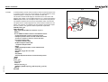
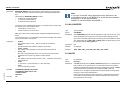
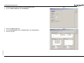
Connect the TJ1-MC__ to Trajexia Studio software. Refer to the
Programming Manual.
Open the terminal window and type the following commands:
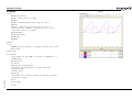
Type PRINT VERSION in the terminal window. The version parameter returns
the current firmware version number of the motion controller.
Type PRINT FPGA_VERSION SLOT(-1) in the terminal window. The
parameter returns the current FPGA version number of the TJ1-MC__.
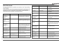
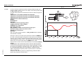
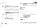
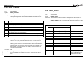
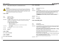
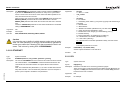
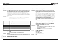
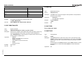
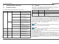
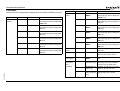
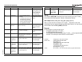
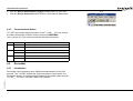
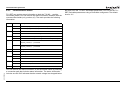
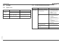
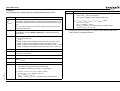
Functions supported by unit versions
During the development of Trajexia new functionality was added to the
controller unit after market release.
This functionality is implemented in the firmware, and/or the FPGA of the
controller unit.
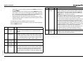
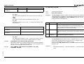
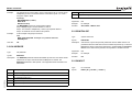
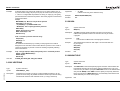
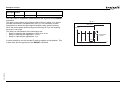
In the table below, the overview of the applicable functionality is shown
related to the firmware and FPGA version of the TJ1-MC__.
/i
Revision 5.0
Functionality
TJ1-MC__ Firmware
version
TJ1-MC__ FPGA
version
Full support TJ1-FL02
V1.6509
21 and higher
Support BASIC commands FINS_COMMS
V1.6509
All versions
Support TJ1-DRT
V1.6509
All versions
Support TJ1-MC04 andTJ1-ML04
V1.6607
21 and higher
Support TJ1-CORT, GRT1-ML2, ModbusTCP, Sigma-V series Servo Drivers
(except DATUM and REGIST BASIC commands) and allow Inverters to be controlled
as servo axes
V1.6652
21 and higher
Support for G-series Drivers, full support for
Sigma-V series Servo Drivers
V1.6714
21 and higher
Support for Accurax G5 Drivers
V1.6720
21 and higher
Verify the firmware and FPGA versions of the TJ1-MC__
PROGRAMMING MANUAL
III
Contents
1
Safety warnings and precautions................................................................................................................................................................ 1
1.1
1.2
1.3
1.4
1.5
1.6
2
Trajexia system ........................................................................................................................................................................................... 6
2.1
2.2
2.3
2.4
2.5
2.6
3
Categories ......................................................................................................................................................................................................................................15
All BASIC commands .....................................................................................................................................................................................................................23
Communication protocols ...................................................................................................................................................................... 179
4.1
4.2
4.3
4.4
4.5
4.6
4.7
4.8
5
Introduction .......................................................................................................................................................................................................................................6
Multitasking BASIC programming.....................................................................................................................................................................................................7
BASIC programming.........................................................................................................................................................................................................................8
Motion execution.............................................................................................................................................................................................................................12
Command line interface ..................................................................................................................................................................................................................13
BASIC programs.............................................................................................................................................................................................................................13
BASIC commands ...................................................................................................................................................................................... 15
3.1
3.2
4
Intended audience ............................................................................................................................................................................................................................1
General precautions .........................................................................................................................................................................................................................1
Safety precautions ...........................................................................................................................................................................................................................1
Operating environment precautions..................................................................................................................................................................................................2
Application precautions.....................................................................................................................................................................................................................3
Unit assembly precautions................................................................................................................................................................................................................5
Available interfaces.......................................................................................................................................................................................................................179
Ethernet ....................................................................................................................................................................................................................................179
Serial protocol ...........................................................................................................................................................................................................................183
PROFIBUS ...................................................................................................................................................................................................................................191
DeviceNet .....................................................................................................................................................................................................................................196
CANopen ......................................................................................................................................................................................................................................202
MECHATROLINK-II
................................................................................................................................................................................................................205
GRT1-ML2 I/O mapping ...............................................................................................................................................................................................................206
Examples and tips .................................................................................................................................................................................... 212
5.1
5.2
How-to’s........................................................................................................................................................................................................................................212
Practical examples........................................................................................................................................................................................................................269
Revision 5.0
PROGRAMMING MANUAL
IV
Contents
6
Troubleshooting........................................................................................................................................................................................ 293
6.1
6.2
6.3
6.4
6.5
6.6
6.7
6.8
A
Voltage and analysis tools ............................................................................................................................................................................................................293
TJ1-MC__ .....................................................................................................................................................................................................................................293
TJ1-PRT .......................................................................................................................................................................................................................................296
TJ1-DRT .......................................................................................................................................................................................................................................297
TJ1-CORT ....................................................................................................................................................................................................................................297
TJ1-ML__......................................................................................................................................................................................................................................298
GRT1-ML2 ....................................................................................................................................................................................................................................298
TJ1-FL02 ......................................................................................................................................................................................................................................301
GRT1-ML2 timing ...................................................................................................................................................................................... 302
Revision history .............................................................................................................................................................................................. 307
Revision 5.0
PROGRAMMING MANUAL
V
Safety warnings and precautions
1
1.1
Safety warnings and precautions
Intended audience
This manual is intended for personnel with knowledge of electrical systems
(electrical engineers or the equivalent) who are responsible for the design,
installation and management of factory automation systems and facilities.
1.2
General precautions
The user must operate the product according to the performance
specifications described in this manual.
Before using the product under conditions which are not described in the
manual or applying the product to nuclear control systems, railroad systems,
aviation systems, vehicles, safety equipment, petrochemical plants, and
other systems, machines and equipment that can have a serious influence
on lives and property if used improperly, consult your OMRON
representative.
1.3
Safety precautions
WARNING
Do not attempt to take the Unit apart and do not touch any of the
internal parts while power is being supplied.
Doing so may result in electrical shock.
WARNING
Do not touch any of the terminals or terminal blocks while power is
being supplied.
Doing so may result in electric shock.
Revision 5.0
PROGRAMMING MANUAL
WARNING
Never short-circuit the positive and negative terminals of the batteries, charge the batteries, disassemble them, deform them by
applying pressure, or throw them into a fire.
The batteries may explode, combust or leak liquid.
WARNING
Fail-safe measures must be taken by the customer to ensure
safety in the event of incorrect, missing, or abnormal signals
caused by broken signal lines, momentary power interruptions, or
other causes.
Not doing so may result in serious accidents.
WARNING
Emergency stop circuits, interlock circuits, limit circuits, and similar
safety measures must be provided by the customer as external circuits, i.e., not in the Trajexia motion controller.
Not doing so may result in serious accidents.
WARNING
When the 24-VDC output (I/O power supply to the TJ1) is overloaded or short-circuited, the voltage may drop and result in the
outputs being turned off.As a countermeasure for such problems,
external safety measures must be provided to ensure safety in the
system.
WARNING
The TJ1 outputs will go off due to overload of the output transistors
(protection).As a countermeasure for such problems, external
safety measures must be provided to ensure safety in the system.
1
Safety warnings and precautions
WARNING
The TJ1 will turn off the WDOG when its self-diagnosis function
detects any error.As a countermeasure for such errors, external
safety measures must be provided to ensure safety in the system.
WARNING
Provide safety measures in external circuits, i.e., not in the Trajexia Motion Controller (referred to as "TJ1"), in order to ensure
safety in the system if an abnormality occurs due to malfunction of
the TJ1 or another external factor affecting the TJ1 operation.
Not doing so may result in serious accidents.
WARNING
Do not attempt to disassemble, repair, or modify any Units.
Any attempt to do so may result in malfunction, fire, or electric
shock.
Caution
Confirm safety at the destination unit before transferring a program
to another unit or editing the memory.
Doing either of these without confirming safety may result in injury.
Caution
User programs written to the Motion Control Unit will not be automatically backed up in the TJ1 flash memory (flash memory function).
Caution
Tighten the screws on the terminal block of the Power Supply Unit
to the torque specified in this manual.
Loose screws may result in burning or malfunction.
1.4
Operating environment precautions
Caution
Do not operate the Unit in any of the following locations.
Doing so may result in malfunction, electric shock, or burning.
- Locations subject to direct sunlight.
- Locations subject to temperatures or humidity outside the
range specified in the specifications.
- Locations subject to condensation as the result of severe
changes in temperature.
- Locations subject to corrosive or flammable gases.
- Locations subject to dust (especially iron dust) or salts.
- Locations subject to exposure to water, oil, or chemicals.
- Locations subject to shock or vibration.
Caution
Take appropriate and sufficient countermeasures when installing
systems in the following locations.
Inappropriate and insufficient measures may result in malfunction.
- Locations subject to static electricity or other forms of noise.
- Locations subject to strong electromagnetic fields.
- Locations subject to possible exposure to radioactivity.
- Locations close to power supplies.
Revision 5.0
Caution
Pay careful attention to the polarity (+/-) when wiring the DC power
supply.A wrong connection may cause malfunction of the system.
PROGRAMMING MANUAL
2
Safety warnings and precautions
Caution
The operating environment of the TJ1 System can have a large
effect on the longevity and reliability of the system.
Improper operating environments can lead to malfunction, failure,
and other unforeseeable problems with the TJ1 System.
Make sure that the operating environment is within the specified
conditions at installation and remains within the specified conditions during the life of the system.
1.5
Caution
Take appropriate measures to ensure that the specified power with
the rated voltage and frequency is supplied. Be particularly careful
in places where the power supply is unstable.
An incorrect power supply may result in malfunction.
Application precautions
Caution
Install external breakers and take other safety measures against
short-circuiting in external wiring.
Insufficient safety measures against short-circuiting may result in
burning.
WARNING
Do not start the system until you check that the axes are present
and of the correct type.
The numbers of the Flexible axes will change if MECHATROLINKII network errors occur during start-up or if the MECHATROLINK-II
network configuration changes.
Caution
Do not apply voltage to the Input Units in excess of the rated input
voltage.
Excess voltage may result in burning.
WARNING
Check the user program for proper execution before actually running it in the Unit.
Not checking the program may result in an unexpected operation.
Caution
Always use the power supply voltage specified in this manual.
An incorrect voltage may result in malfunction or burning.
Caution
Do not apply voltage or connect loads to the Output Units in
excess of the maximum switching capacity.
Excess voltage or loads may result in burning.
Caution
Disconnect the functional ground terminal when performing withstand voltage tests.
Not disconnecting the functional ground terminal may result in
burning.
Revision 5.0
PROGRAMMING MANUAL
3
Safety warnings and precautions
Caution
Always connect to a class-3 ground (to 100Ω or less) when installing the Units.
Not connecting to a class-3 ground may result in electric shock.
Caution
Always turn off the power supply to the system before attempting
any of the following.
Not turning off the power supply may result in malfunction or electric shock.
- Mounting or dismounting expansion Units, CPU Units, or any
other Units.
- Assembling the Units.
- Setting dipswitches or rotary switches.
- Connecting or wiring the cables.
- Connecting or disconnecting the connectors.
Caution
Use crimp terminals for wiring. Do not connect bare stranded wires
directly to terminals.
Connection of bare stranded wires may result in burning.
Caution
Double-check all the wiring before turning on the power supply.
Incorrect wiring may result in burning.
Caution
Wire correctly.
Incorrect wiring may result in burning.
Caution
Mount the Unit only after checking the terminal block completely.
Caution
Be sure that all mounting screws, terminal screws, and cable connector screws are tightened to the torque specified in this manual.
Incorrect tightening torque may result in malfunction.
Caution
Be sure that the terminal blocks, expansion cables, and other
items with locking devices are properly locked into place.
Improper locking may result in malfunction.
Caution
Leave the dust protective label attached to the Unit when wiring.
Removing the dust protective label may result in malfunction.
Caution
Confirm that no adverse effect will occur in the system before
changing the operating mode of the system.
Not doing so may result in an unexpected operation.
Revision 5.0
Caution
Remove the dust protective label after the completion of wiring to
ensure proper heat dissipation.
Leaving the dust protective label attached may result in malfunction.
PROGRAMMING MANUAL
4
Safety warnings and precautions
Caution
Resume operation only after transferring to the new CPU Unit the
contents of the VR and table memory required for operation.
Not doing so may result in an unexpected operation.
Caution
Use the dedicated connecting cables specified in operation manuals to connect the Units.Using commercially available RS-232C
computer cables may cause failures in external devices or the
Motion Control Unit.
Caution
When replacing parts, be sure to confirm that the rating of a new
part is correct.
Not doing so may result in malfunction or burning.
Caution
Outputs may remain on due to a malfunction in the built-in transistor outputs or other internal circuits.As a countermeasure for such
problems, external safety measures must be provided to ensure
the safety of the system.
Caution
Do not pull on the cables or bend the cables beyond their natural
limit. Doing so may break the cables.
Caution
Before touching the system, be sure to first touch a grounded
metallic object in order to discharge any static build-up.
Otherwise it might result in a malfunction or damage.
Revision 5.0
Caution
UTP cables are not shielded. In environments that are subject to
noise use a system with shielded twisted-pair (STP) cable and
hubs suitable for an FA environment.
Do not install twisted-pair cables with high-voltage lines.
Do not install twisted-pair cables near devices that generate noise.
Do not install twisted-pair cables in locations that are subject to
high humidity.
Do not install twisted-pair cables in locations subject to excessive
dirt and dust or to oil mist or other contaminants.
PROGRAMMING MANUAL
Caution
The TJ1 will start operating in RUN mode when the power is
turned on and if a BASIC program is set to Auto Run mode.
1.6
Unit assembly precautions
Caution
Install the unit properly.
Improper installation of the unit may result in malfunction.
Caution
Be sure to mount the Termination Unit supplied with the TJ1MC__ to the right most Unit.
Unless the Termination Unit is properly mounted, the TJ1 will not
function properly.
5
Trajexia system
2
Trajexia system
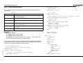
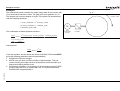
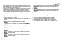
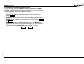
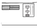
2.1
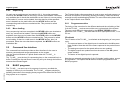
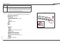
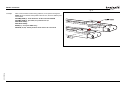
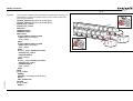
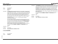
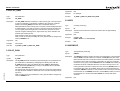
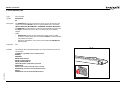
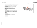
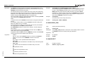
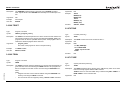
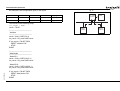
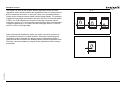
Introduction
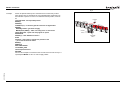
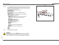
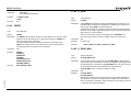
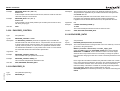
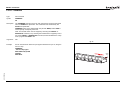
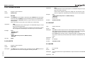
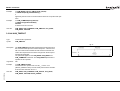
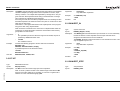
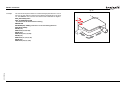
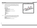
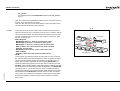
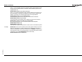
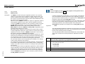
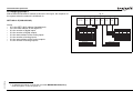
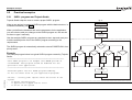
Trajexia is OMRON's motion platform that offers you the performance and
the ease of use of a dedicated motion system.
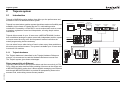
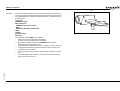
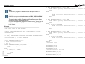
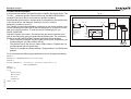
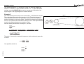
fig. 1
CJ-series PLC
Trajexia is a stand-alone modular system that allows maximum flexibility and
scalability. At the heart of Trajexia lies the TJ1 multi-tasking motion
coordinator. Powered by a 32-bit DSP, it can do motion tasks such as e-cam,
e-gearbox, registration control and interpolation, all using simple motion
commands.
Trajexia offers control of up to 16 axes over a MECHATROLINK-II motion
bus or traditional analogue or pulse control with independent position, speed
or torque control for every axis. And its powerful motion instruction set
makes programming intuitive and easy.
You can select from a wide choice of best-in-class rotary, linear and directdrive servos as well as Inverters. The system is scalable up to 16 axes and 8
Inverters & I/O modules.
2.1.1
NS-series HMI
CX-one
Trajexia Tools
PROFIBUS-DP
Master
DEVICENET
Master
CANopen
Master
Ethernet
Digital I/O
Hostlink
MECHATROLINK-II
Trajexia hardware
The Trajexia hardware is described in the Trajexia Hardware Reference
manual. It is recommend to read the Hardware Reference manual first.
The Trajexia system gives these advantages:
Direct connectivity via Ethernet
Revision 5.0
Trajexia's Ethernet built-in port provides direct and fast connectivity to PCs,
PLCs, HMIs and other devices while providing full access to the drives over
a MECHATROLINK-II motion bus. It allows explicit messaging over Ethernet
and through MECHATROLINK-II to provide full transparency down to the
actuator level, and making remote access possible.
PROGRAMMING MANUAL
6
Trajexia system
Keep your know-how safe
DeviceNet
Trajexia's encryption method guarantees complete protection and
confidentiality for your valuable know-how.
The DeviceNet slave allows connectivity to the DeviceNet network in your
machine.
Serial Port and Local I/Os
CANopen
A serial port provides direct connectivity with any OMRON PLC, HMIs or any
other field device. 16 Inputs and 8 outputs are freely configurable embedded
I/Os in the controller to enable you to tailor Trajexia to your machine design.
The CANopen master allows connectivity to the CANopen network in your
machine.
MECHATROLINK-II Master
The MECHATROLINK-II master performs control of up to 16 servos,
Inverters or I/Os while allowing complete transparency across the whole
system.MECHATROLINK-II offers the communication speed and time
accuracy essential to guarantee perfect motion control of servos. The
motion cycle time is selectable between 0.5 ms, 1 ms or 2 ms.
TJ1-FL02 (Flexible Axis Unit)
The TJ1-FL02 allows full control of two actuators via an analogue output or
pulse train. The module supports the main absolute encoder protocols
allowing the connection of an external encoder to the system.
Drives and Inverters
A wide choice of rotary, linear and direct-drive servos as well as Inverters
are available to fit your needs in compactness, performance and reliability.
The Inverters connected to the MECHATROLINK-II are driven at the same
update cycle time as the Servo Drivers.
Remote I/Os
The I/Os on the MECHATROLINK-II motion bus provide for system
expansion while keeping the devices under one motion bus.
PROFIBUS-DP
2.1.2
This manual
This Programming Manual gives the dedicated information for:
• The description and use of the BASIC commands
• The communication protocols necessary for the Trajexia system
• The use and description of the parts of the Trajexia Studio interface
• Program examples and good programming practices
• Troubleshooting and fault finding.
2.2
Multitasking BASIC programming
The TJ1-MC__ units (Motion Controller Unit) feature a multitasking version
of the BASIC programming language. The motion control language is largely
based upon a tokenised BASIC and the programs are compiled into the
tokenised form prior to their execution.
Multitasking is simple to set up and use and allows very complex machines
to be programmed. Multitasking gives the TJ1-MC__ a significant advantage
over equivalent single task systems. It allows modular applications where
the logically connected processes can be grouped together in the same task
program, thus simplifying the code architecture and design.
The TJ1-MC__ can hold up to 14 programs if memory size permits. The
execution of the programs is user controlled using BASIC.
The BASIC commands, functions and parameters presented here can be
found in chapter 3.
Revision 5.0
The PROFIBUS-DP slave allows connectivity to the PROFIBUS network in
your machine.
PROGRAMMING MANUAL
7
Trajexia system
2.3
BASIC programming
The BASIC language consists among others of commands, functions and
parameters. These BASIC statements are the building blocks provided to
control the TJ1-MC__ operation.
Commands are words recognized by the processor that perform a certain
action but do not return a value. For example, PRINT is a recognized word
that will cause the value of the following functions or variables to be printed
on a certain output device.
Functions are words recognized by the processor that perform a certain
action and return a value related to that action. For example, ABS will take
the value of its parameter and return the absolute value of it to be used by
some other function or command. For example ABS(-1) will return the value
1, which can be used by the PRINT command, for example, to generate a
string to be output to a certain device.
Parameters are words recognized by the processor that contain a certain
value. This value can be read and, if not read only, written. Parameters are
used to determine and monitor the behavior of the system. For example,
ACCEL determines the acceleration rate of a movement for a certain axis.
Individual axis dependent commands or parameters can also be
programmed to work on a temporary base axis by including the AXIS
function as a modifier in the axis dependent command. A temporary base
axis is effective only for the command or parameter after which AXIS
appears.
Task statements
The task parameters apply to a single task. The task parameters monitor the
task for example for error handling. The PROC modifier allows the user to
access a parameter of a certain task. Without PROC the current task is
assumed. The BASE command (see above) is task specific and can be
used with the PROC modifier.
System statements
These statements govern the overall system features, which are basically all
statements which do not belong to the first two groups.
2.3.2
Memory areas
The commands, functions and parameters apply either to (one of) the axes,
the tasks running or the general system.
Three main memory areas can be identified in the Trajexia Motion Controller
Unit:
• I/O memory.
• VR memory.
• TABLE memory.
Axis statements
I/O memory
2.3.1
Axis, system and task statements
Revision 5.0
The motion control commands and the axis parameters apply to one or more
axes. Axis parameters determine and monitor how an axis reacts on
commands given and how it reacts to the outside world. Every axis has a set
of parameters, so that all axes can work independently of each other. The
motion control commands are able to control one or more of the axes
simultaneously, while every axis has its own behavior. The axis parameters
are reset to their default values for each startup.
The commands and parameters work on some base axis or group of axes,
specified by the BASE command. The BASE command is used to change
this base axis group and every task has its own group which can be changed
at any time. The default base axis is 0.
PROGRAMMING MANUAL
I/O memory is used for holding the status of input and output devices
connected to the Trajexia system. It is divided into two sub-areas: one for
digital I/O memory, and one for analog I/O memory. The digital I/O memory
holds input and output statuses of digital I/O devices. Its capacity is 256 bits
(input points) for input and 256 bits (output points) for outputs. The inputs in
this memory can be accessed using the IN command. The outputs can be
accessed using the OUT command.
The analog I/O memory holds input and output values of analog I/O devices.
Its capacity is 36 input channels and 36 output channels. The analog input
channels can be accessed using the AIN command. The analog output
channels can be accessed using the AOUT command.
8
Trajexia system
VR memory
VR memory is commonly used if some data or value needs to be global,
which means that it is accessible from all programs in the project at the
same time. The size of this memory is 1024 slots with indexes 0 to 1023. A
memory slot is addressed using the VR(x) macro where x is index of the VR
memory slot. The VR memory is accessible for reading and writing. Writing
is done by making mathematical assignment using the = command in the
program. The content of this memory is held in the battery powered RAM
memory and is preserved during power off. The VR memory is also
preserved when changing the battery, if this is done quickly.
TABLE memory
TABLE is commonly used if some data or value needs to be global, which
means that it is accessible from all programs in the project at the same time.
Whereas the VR memory is used for similar purposes to define several
global data and values, TABLE memory is used for much bigger amounts of
global data, which also need to be arranged in a certain order. For this
reason, TABLE memory is commonly used for storing TABLE data, motion
profiles, logging data, etc. Some BASIC commands that provide this type
and size of data, for example SCOPE, CAM, CAMBOX etc., require use of
TABLE memory to write their results. The size of this memory is 64000 slots
with indexes 0 to 63999. The TABLE is accessible for reading and writing
too, but the way it is accessed differs for those two operations. Before being
read, a particular TABLE memory slot needs to be defined and written first,
using the command TABLE(x, value1, value2,…) where x is the index of
the start TABLE memory slot to define, and value1, value2, ... are the
values written into the TABLE memory at indexes x, x+1, ... Once defined
and written, the TABLE memory slot can be read using the TABLE(x)
command, where x is the index of the TABLE memory slot. An attempt to
read an undefined TABLE memory slot results in an error reported by the
TJ1-MC__. The TABLE memory content is held in the battery powered RAM
memory and is preserved during power off. The TABLE memory is also
preserved when changing the battery, if this is done quickly.
2.3.3
Data structures and variables
BASIC programs can store numerical data in various types of variables.
Some variables have predefined functions, such as the axis parameters and
system parameters; other variables are available for the programmer to
define as required in programming. The TABLE, global and local variables of
the TJ1-MC__ are explained in this section. Furthermore also the use of
labels will be specified.
TABLE variables
The TABLE is an array structure that contains a series of numbers. These
numbers are used for instance to specify positions in the profile for a CAM or
CAMBOX command. They can also be used to store data for later use, for
example to store the parameters used to define a workpiece to be
processed.
The TABLE is common to all tasks on the TJ1-MC__. This means that the
values written to the TABLE from one task can be read from other tasks.
TABLE values can be written and read using the TABLE command. The
maximum length of the array is 64000 elements, from TABLE(0) to
TABLE(63999). The TABLE array is initialized up to the highest defined
element.
Global variables
The global variables, defined in VR memory, are common to all tasks on the
TJ1-MC__. This means that if a program running on task 2 sets VR(25) to a
certain value, then any other program running on a different task can read
that same value from VR(25). This is very useful for synchronizing two or
more tasks, but care must be taken to avoid more than one program writing
to the same variable at the same time. The controller has 1024 global
variables, VR(0) to VR(1023). The variables are read and written using the
VR command.
Revision 5.0
PROGRAMMING MANUAL
9
Trajexia system
/i
Note
The TABLE and VR data can be accessed from the different running tasks. When using either VR or TABLE variables, make sure
to use only one task to write to one particular variable. This to
avoid problems of two program tasks writing unexpectedly to one
variable.
Local variables
Named variables or local variables can be declared in programs and are
local to the task. This means that two or more programs running on different
tasks can use the same variable name, but their values can be different.
Local variables cannot be read from any task except for the one in which
they are declared. Local variables are always cleared when a program is
started. The local variables can be cleared by using either the CLEAR or the
RESET command.
A maximum of 255 local variables can be declared. Only the first 16
characters of the name are significant. Undefined local variables will return
zero. Local variables cannot be declared on the command line.
Labels
The BASIC programs are executed in descending order through the lines.
Labels can be used to alter this execution flow using the BASIC commands
GOTO and GOSUB. To define a label it must appear as the first statement
on a line and it must be ended by a colon (:). Labels can be character strings
of any length, but only the first 15 characters are significant.
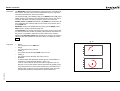
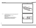
Using variables and labels
Each task has its own local labels and local variables. For example, consider
the two programs shown below:
Revision 5.0
PROGRAMMING MANUAL
start:
FOR a = 1 to 100
MOVE(a)
WAIT IDLE
NEXT a
GOTO start
start:
a=0
REPEAT
a = a + 1
PRINT a
UNTIL a = 300
GOTO start
These two programs when run simultaneously in different tasks and have
their own version of variable a and label start.
If you need to hold data in common between two or more programs, VR
variables should be used. Or alternatively if the large amount of data is to be
held, the TABLE memory can be used.
To make a program more readable when using a global VR variable, two
approaches can be taken. The first is using a named local variable as a
constant in the VR variable. The local constant variable, however, must be
declared in each program using the global VR variable. Using this approach,
the example below shows how to use VR(3) to hold a length parameter
common for several programs:
/i
start:
GOSUB Initial
VR(length) = x
...
...
start:
GOSUB Initial
MOVE(VR(length))
PRINT(VR(length))
...
Initial:
length = 3
RETURN
Initial:
length = 3
RETURN
The other approach is even more readable and uses the GLOBAL
command to declare the name as a reference to one of the global VR
variables. The name can then be used from within the program containing
the GLOBAL definition and all other programs. Take care that the program
containing the GLOBAL definition must be run before the name is used in
other programs. The best practice is to define global names in the start-up
program. Using this approach, the example above becomes:
10
Trajexia system
/i
'The declaration in start-up program
GLOBAL length, 3
'In other programs executed after the start-up program
start:
length = x
...
...
2.3.4
start:
MOVE(length)
PRINT(length)
...
Mathematical specifications
Number format
The TJ1-MC__ has two main formats for numeric values: single precision
floating point and single precision integer.
The single precision floating point format is internally a 32 bit value. It has an
8 bit exponent field, a sign bit and a 23 bit fraction field with an implicit 1 as
the 24th bit. Floating point numbers have a valid range of ±5.9×10−39 to
±3.4×1038.
Integers are essentially floating point numbers with a zero exponent. This
implies that the integers are 24 bits wide. The integer range is therefore
given from -16,777,216 to 16,777,215. Numeric values outside this range
will be floating point.
WARNING
All mathematical calculations are done in floating point format. This
implies that for calculations of/with larger values the results may
have limited accuracy. The user should be aware of this when
developing the motion control application.
Hexadecimal format
Revision 5.0
The TJ1-MC__ supports assigning and printing hexadecimal values. A
hexadecimal number is input by prefixing the number with the $ character.
Valid range is from 0x0 to 0xFFFFFF. Example:
PROGRAMMING MANUAL
>> VR(0)=$FF
>> PRINT VR(0)
255.0000
A value can be printed in hexadecimal by using the HEX function. Negative
values result in the 2’s complement hexadecimal value (24-bit). Valid range
is from −8,388,608 to 16,777,215. Example:
>> TABLE(0,-10,65536)
>> PRINT HEX(TABLE(0)),HEX(TABLE(1))
FFFFF6 10000
Positioning
For positioning, the TJ1-MC__ will round up if the fractional encoder edge
distance calculated exceeds 0.9. Otherwise the fractional value will be
rounded down. The internal measured position and demanded position of
the axes, represented by the MPOS and DPOS axis parameters, have 32-bit
counters.
Floating point comparison
The comparison function considers a small difference between values as
equal to avoid unexpected comparison results. Therefore any two values for
which the difference is less than 1.19×10⁻⁶ are considered equal.
Precedence
The precedence of the operators is given below:
1. Unary minus, NOT
2. ^
3. / *
4. MOD
5. + 6. = <> > >= <= <
7. AND OR XOR
8. Left to right
The best way to ensure the precedence of various operators is through the
use of parentheses.
11
Trajexia system
2.4
Motion execution
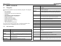
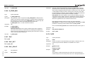
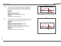
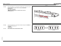
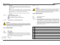
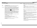
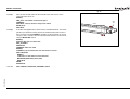
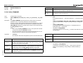
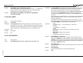
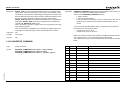
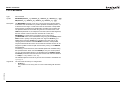
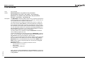
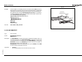
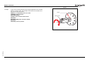
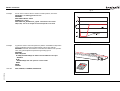
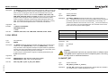
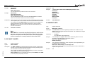
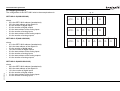
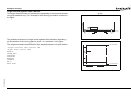
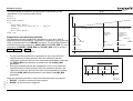
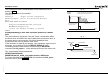
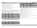
Every task on the TJ1-MC__ has a set of buffers that holds the information
from the motion commands given.
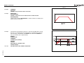
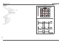
2.4.1
Motion generator
The motion generator has a set of two motion buffers for each axis. One
buffer called MTYPE, holds the Actual Move, which is the move currently
executing on the axis. The other buffer called NTYPE, holds the Next Move,
which is executed after the Actual Move has finished.
See chapter 2.8 “Motion Buffers” in the Trajexia Hardware Reference
manual for detailed explanation.
The BASIC programs are separate from the motion generator program,
which controls moves for the axes. The motion generator has separate
functions for each axis, so each axis is capable of being programmed with its
own axis parameters (for example speed, acceleration) and moving
independently and simultaneously or they can be linked together using
special commands.
When a move command is being processed, the motion generator waits until
the move is finished and the buffer for the required axis has become empty,
and then loads these buffers with the next move information.
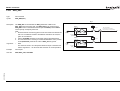
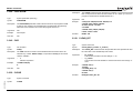
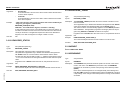
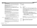
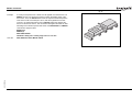
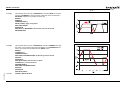
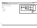
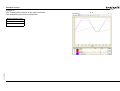
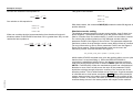
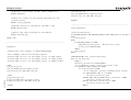
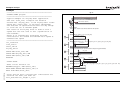
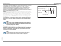
fig. 2
Note
If the task buffers are full, the program execution is paused until
buffers are available again. This also applies to the command line
task and no commands can be given for that period. Trajexia Studio will disconnect in such a case. The PMOVE task parameter will
be set to TRUE when the task buffers are full and will be reset to
FALSE when the task buffers are available again.
Task buffers
Task 1
MOVECIRC(..) AXIS(0)
FORWARD AXIS(1)
Motion
Generator
Task 2
Task 3
MOVE(..) AXIS(0)
Sequencing
Move buffers
Axis
0
Revision 5.0
Next Move (NTYPE) MOVE (1)
1
Next Move (NTYPE) MOVECIRC (4) MOVECIRC (4)
PROGRAMMING MANUAL
2
FORWARD (10) IDLE (0)
Move
Loading
IDLE (0)
12
Trajexia system
2.4.2
Sequencing
On each servo cycle interrupt (see section 2.6.1), the motion generator
examines the NTYPE buffers to see if any of them are available. If there are
any available then it checks the task buffers to see if there is a move waiting
to be loaded. If a move can be loaded, then the data for all the specified
axes is loaded from the task buffers into the NTYPE buffers and the
corresponding task buffers are marked as idle. This process is called
sequencing.
2.4.3
Move loading
Once sequencing has been completed, the MTYPE buffers are checked to
see if any moves can be loaded. If the required MTYPE buffers are
available, then the move is loaded from the NTYPE buffers to the MTYPE
buffers and the NTYPE buffers are marked as idle. This process is called
move loading. If there is a valid move in the MTYPE buffers, then it is
processed. When the move has been completed, the MTYPE buffers are
marked as idle.
2.5
Command line interface
The command line interface provides a direct interface for the user to
execute commands and access parameters on the system.
Use the Terminal Window in Trajexia Studio when the TJ1-MC__ is
connected.
The TJ1-MC__ puts the last 10 commands given on the command line in a
buffer. Pressing the Up and Down Cursor Key will cycle through the buffer to
execute the command again.
2.6
The Trajexia Studio software package is used to store and load programs to
and from a computer for archiving, printing and editing. It also has several
controller monitor and debugging facilities. For more information please refer
to the Trajexia Studio user manual.
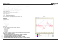
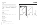
2.6.1
Program execution
The timing of the execution for the different tasks and the refreshing of the I/
O of the TJ1-MC__ revolves around the servo cycle period of the system.
The servo cycle period is determined by the SERVO_PERIOD system
parameter. The TJ1-MC__ will either have a servo cycle period of 0.5, 1.0 or
2.0 ms.
I/O refresh
The I/O status of the TJ1-MC__ is refreshed at the beginning of every servo
cycle.
• The captured status of the digital inputs is transferred to the IN system
input variable. Note that this is the status captured in the previous servo
cycle.
• The analogue outputs for the speed references are updated.
• The digital outputs are updated conform the status of the OP system
output variable.
• The status of the digital inputs is captured.
Note that no automatic processing of the I/O signals is taking place, except
for registration. This implies that all actions must be programmed in the
BASIC programs.
BASIC programs
Revision 5.0
The TJ1-MC__ can store up to 14 programs in memory, provided the
capacity of memory is not exceeded. The TJ1-MC__ supports simple filehandling instructions for managing these program files rather like the DOS
filing system on a computer.
PROGRAMMING MANUAL
13
Trajexia system
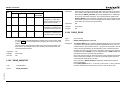
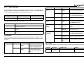
Relevant commands
Trajexia Studio provides several ways of executing, pausing and stopping
the programs using buttons on the control panel and the editing windows.
The following commands can be given on the command line to control the
execution.
/i
Command
Function
RUN
Run the current selected program or a specified program, optionally on a
specified task number.
STOP
Stop the current selected program or a specified program.
HALT
Stop all programs on the system.
PROCESS
Displays all running tasks.
The user can explicitly allocate the task priority on which the BASIC program
is expected to run. When a user program is run without explicit task
allocation, it is assigned the highest available task priority.
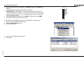
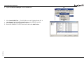
Setting programs to run at start-up
Programs can be set to run automatically at different priorities when power is
turned on. If required, the computer can be left connected as an operator
interface or may be removed and the programs run stand-alone.
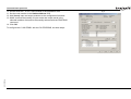
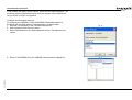
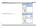
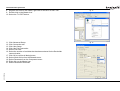
Programs are set in Trajexia Studio to run automatically at start-up by setting
the startup priority with the Priority property in the Properties window. If you
click the ellipsis button in the edit field of this property, the StartUp Priority
window shows. To set the program to run at power up, select the Run at
Power Up check box and select a priority in the list. Possible priority values
are Default or 1 (lowest priority) to 14 (highest priority).The current status in
the controller can be seen using the DIR command.
For more information on program control, multitasking and cycle times, refer
to sections 2.2 and 2.3 of the Trajexia Hardware Reference Manual.
Revision 5.0
PROGRAMMING MANUAL
14
BASIC commands
3
3.1
BASIC commands
Categories
This section lists all BASIC commands divided by categories. The categories
are:
• Axis commands.
• Axis parameters.
• Communication commands and parameters.
• Constants.
• I/O commands, functions and parameters.
• Mathematical functions and operations.
• Program commands.
• Program control commands.
• Slot parameters and modifiers.
• System commands and functions.
• System parameters.
• Task commands and parameters.
Name
Description
BASE
Used to set the base axis to which the commands and parameters
are applied.
CAM
Moves an axis according to values of a movement profile stored in
the TABLE variable array.
CAMBOX
Moves an axis according to values of a movement profile stored in
the TABLE variable array. The motion is linked to the measured
motion of another axis to form a continuously variable software gearbox.
CANCEL
Cancels the move on an axis.
CONNECT
Connects the demand position of an axis to the measured movements of the driving axis to produce an electronic gearbox.
DATUM
Performs one of 7 origin search sequences to position an axis to an
absolute position or reset a motion error.
DEFPOS
Defines the current position as a new absolute position.
DISABLE_GROUP
Groups axes together for error disabling.
DRIVE_ALARM
Monitors the current alarm.
The lists are quick reference guides only. A complete description of the
commands is given in alphabetical order in the next section.
DRIVE_CLEAR
Clears the alarm status of the Servo Driver.
DRIVE_READ
Reads the specified parameter of the Servo Driver.
3.1.1
DRIVE_RESET
Resets the Servo Driver.
DRIVE_WRITE
Writes a specific value to the specified parameter of the Servo
Driver.
FORWARD
Moves an axis continuously forward at the speed set in the SPEED
parameter.
Axis commands
/i
Revision 5.0
Name
Description
ACC
Changes the ACCEL and DECEL at the same time.
ADD_DAC
Sum to the DAC value of one axis to the analogue output of the
base axis.
HW_PSWITCH
Sets on and off the hardware switch on output 0 of the TJ1-FL02
when predefined positions are reached.
ADDAX
Sets a link to a superimposed axis. All demand position movements
for the superimposed axis will be added to any moves that are currently being executed.
MECHATROLINK
Initializes MECHATROLINK-II bus and performs various operations
on MECHATROLINK-II stations connected to the bus.
MHELICAL
Interpolates 3 orthogonal axes in a helical move.
B_SPLINE
Expands the profile stored in TABLE memory using the B-Spline
mathematical function.
MOVE
BACKLASH
Allows the backlash compensation to be loaded.
Moves one or more axes at the demand speed, acceleration and
deceleration to the position specified as increment from the current
position.
PROGRAMMING MANUAL
15
BASIC commands
Name
Description
Name
Description
MOVEABS
Moves one or more axes at the demand speed, acceleration and
deceleration to the position specified as absolute position.
CREEP
Contains the creep speed.
D_GAIN
Contains the derivative control gain.
MOVECIRC
Interpolates 2 orthogonal axes in a circular arc.
DAC_SCALE
Sets scale and polarity applied to DAC values.
MOVELINK
Creates a linear move on the base axis linked via a software gearbox to the measured position of a link axis.
DATUM_IN
Contains the input number to be used as the origin input.
MOVEMODIFY
Changes the absolute end position of the current single-axis linear
move (MOVE or MOVEABS).
DECEL
Contains the axis deceleration rate.
DEMAND_EDGES
RAPIDSTOP
Cancels the current move on all axes.
Contains the current value of the DPOS axis parameter in
encoder edges.
REGIST
Captures an axis position when a registration input or the Z mark on
the encoder is detected.
DPOS
Contains the demand position generated by the move commands.
REVERSE
Moves an axis continuously in reverse at the speed set in the
SPEED parameter.
DRIVE_CONTROL
STEP_RATIO
Sets the ratio for the axis stepper output.
Selects data to be monitored using DRIVE_MONITOR for axes
connected via the MECHATROLINK-II bus. For axes connected
via the TJ1-FL02, DRIVE_CONTROL sets outputs of the TJ1FL02.
DRIVE_INPUTS
Holds I/O data of the driver connected to MECHATROLINK-II
bus. Data is updated every servo cycle.
DRIVE_MONITOR
Monitors data of the Servo Driver connected to MECHATROLINK-II bus. Data are updated every servo cycle.
DRIVE_STATUS
Contains the current status of the Servo Driver.
ENCODER
Contains a raw copy of the encoder hardware register.
ENCODER_BITS
Sets the number of bits for the absolute encoder connected to
TJ1-FL02.
ENCODER_CONTROL
Controls operating mode of the EnDat absolute encoder.
ENCODER_ID
Returns the ID value of the absolute encoder connected to TJ1FL02.
ENCODER_RATIO
Sets scaling value for incoming encoder counts.
ENCODER_STATUS
Returns the status of the Tamagawa absolute encoder.
ENCODER_TURNS
Returns the multi-turn count of the absolute encoder.
ENDMOVE
Holds the position of the end of the current move.
ERRORMASK
Contains the mask value that determines if MOTION_ERROR
occurs depending on the axis status.
3.1.2
Axis parameters
/i
Revision 5.0
Name
Description
ACCEL
Contains the axis acceleration rate.
ADDAX_AXIS
Contains the number of the axis to which the base axis is currently linked to by ADDAX.
ATYPE
Contains the axis type.
AXIS_DISPLAY
Selects information that are represented by the LEDs on the
front cover of the TJ1-FL02.
AXIS_ENABLE
Enables and disables particular axis independently of other axis.
AXISSTATUS
Contains the axis status.
BACKLASH_DIST
Defines the amount of backlash compensation.
CLOSE_WIN
Defines the end of the window in which a registration mark is
expected.
CLUTCH_RATE
Defines the change in connection ratio when using the
CONNECT command.
PROGRAMMING MANUAL
16
BASIC commands
Name
Description
Name
Description
FAST_JOG
Contains the input number to be used as the fast jog input.
OPEN_WIN
FASTDEC
Defines ramp to zero deceleration ratio when an axis limit switch
or position is reached.
Defines the beginning of the window in which a registration
mark is expected.
OUTLIMIT
Contains the limit that restricts the speed reference output from
the TJ1-MC__.
OV_GAIN
Contains the output velocity control gain.
P_GAIN
Contains the proportional control gain.
FE
Contains the Following Error.
FE_LATCH
Contains the FE value which caused the axis to put controller in
MOTION_ERROR state.
Revision 5.0
FE_LIMIT
Contains the maximum allowable Following Error.
REG_POS
Contains the position at which a registration event occurred.
FE_LIMIT_MODE
Defines how FE influences MOTION_ERROR state.
REG_POSB
FE_RANGE
Contains the Following Error warning range limit.
Contains the position at which the secondary registration event
occurred.
FHOLD_IN
Contains the input number to be used as the feedhold input.
REMAIN
Is the distance remaining to the end of the current move.
FHSPEED
Contains the feedhold speed.
REP_DIST
Contains or sets the repeat distance.
FS_LIMIT
Contains the absolute position of the forward software limit.
REP_OPTION
Controls the application of the REP_DIST axis parameter.
FWD_IN
Contains the input number to be used as a forward limit input.
REV_IN
Contains the input number to be used as a reverse limit input.
FWD_JOG
Contains the input number to be used as a jog forward input.
REV_JOG
Contains the input number to be used as a jog reverse input.
I_GAIN
Contains the integral control gain.
RS_LIMIT
Contains the absolute position of the reverse software limit.
INVERT_STEP
Switches a hardware Inverter into the stepper output circuit.
S_REF
JOGSPEED
Sets the jog speed.
Contains the speed reference value which is applied when the
axis is in open loop.
S_REF_OUT
MARK
Detects the primary registration event on a registration input.
Contains the speed reference value being applied to the Servo
Driver for both open as closed loop.
MARKB
Detects the secondary registration event on a registration input.
SERVO
MERGE
Is a software switch that can be used to enable or disable the
merging of consecutive moves.
Determines whether the axis runs under servo control or open
loop.
SPEED
Contains the demand speed in units/s.
MPOS
Is the position of the axis as measured by the encoder.
SPEED_SIGN
MSPEED
Represents the change in the measured position in the last
servo period.
Configures the voltage range of the analog speed reference output of the TJ1-FL02.
SRAMP
Contains the S-curve factor.
MTYPE
Contains the type of move currently being executed.
T_REF
NTYPE
Contains the type of the move in the Next Move buffer.
Contains the torque reference value which is applied to the
servo motor.
OFFPOS
Contains an offset that will be applied to the demand position
without affecting the move in any other way.
TRANS_DPOS
Contains axis demand position at output of frame transformation.
UNITS
Contains the unit conversion factor.
PROGRAMMING MANUAL
17
BASIC commands
Name
Description
3.1.4
VERIFY
Selects different modes of operation on a stepper output axis.
/i
VFF_GAIN
Contains the speed feed forward control gain.
Name
Description
VP_SPEED
Contains the speed profile speed.
FALSE
Equal to the numerical value 0.
OFF
Equal to the numerical value 0.
ON
Equal to the numerical value 1.
PI
Equal to the numerical value 3.1416.
TRUE
Equal to the numerical value -1.
3.1.3
Communication commands and parameters
/i
Name
Description
FINS_COMMS
Sends FINS Read Memory and Write Memory to a designated
FINS server unit.
HLM_COMMAND
Executes a specific Host Link command to the Slave.
HLM_READ
Reads data from the Host Link Slave to either VR or TABLE variable array.
3.1.5
Constants
I/O commands, functions and parameters
/i
Name
Description
Represents the status of the last Host Link Master command.
AIN
Holds the value of the analog channel.
HLM_TIMEOUT
Defines the Host Link Master timeout time.
AOUT
Holds the value of the analog channel.
HLM_WRITE
Writes data to the Host Link Slave from either VR or TABLE variable array.
GET
Waits for the arrival of a single character and assigns the ASCII
code of the character to variable.
HLS_NODE
Defines the Slave unit number for the Host Link Slave protocol.
IN
Returns the value of digital inputs.
SETCOM
Sets the serial communications.
INDEVICE
Parameter defines the default input device.
INPUT
Waits for a string to be received and assigns the numerical value
to variable.
KEY
Returns TRUE or FALSE depending on if character is received.
LINPUT
Waits for a string and puts it in VR variables.
OP
Sets one or more outputs or returns the state of the first 24 outputs.
OUTDEVICE
Defines the default output device.
PRINT
Outputs a series of characters to a serial port.
PSWITCH
Turns on an output when a predefined position is reached, and
turns off the output when a second position is reached.
READ_OP
Returns the value of the digital outputs.
Revision 5.0
HLM_STATUS
PROGRAMMING MANUAL
18
BASIC commands
3.1.6
Mathematical functions and operands
/i
Name
Description
FRAC
Returns the fractional part of an expression.
IEEE_IN
Returns floating point number in IEEE format, represented by 4
bytes.
IEEE_OUT
Returns single byte extracted from the floating point number in
IEEE format.
Revision 5.0
Name
Description
+ (ADDITION)
Adds two expressions.
- (SUBTRACTION)
Subtracts two expressions.
* (MULTIPLICATION)
Multiplies two expressions.
INT
Returns the integer part of an expression.
/ (DIVISION)
Divides two expressions.
LN
Returns the natural logarithm of an expression.
^ (POWER)
Takes the power of one expression to the other expression.
MOD
Returns the modulus of two expressions.
= (IS EQUAL TO)
Checks two expressions to see if they are equal.
NOT
= (ASSIGNMENT)
Assigns an expression to a variable.
Performs a NOT operation on corresponding bits of the integer
part of the expression.
<> (IS NOT EQUAL
TO)
Checks two expressions to see if they are different.
OR
Performs an OR operation between corresponding bits of the
integer parts of two expressions.
> (IS GREATER THAN) Checks two expressions to see if the expression on the left is
greater than the expression on the right.
SGN
Returns the sign of an expression.
SIN
Returns the sine of an expression.
>= (IS GREATER
THAN OR EQUAL TO)
Checks two expressions to see if the expression on the left is
greater than or equal to the expression on the right.
SQR
Returns the square root of an expression.
< (IS LESS THAN)
Checks two expressions to see if the expression on the left is
less than the expression on the right.
TAN
Returns the tangent of an expression.
XOR
<= (IS LESS THAN OR
EQUAL TO)
Checks two expressions to see if the expression on the left is
less than or equal to the expression on the right.
Performs an XOR function between corresponding bits of the
integer parts of two expressions.
ABS
Returns the absolute value of an expression.
ACOS
Returns the arc-cosine of an expression.
AND
Performs an AND operation on corresponding bits of the integer
parts of two expressions.
Name
Description
' (COMMENT FIELD)
Enables a line not to be executed.
ASIN
Returns the arc-sine of an expression.
Enables more statements on one line.
ATAN
Returns the arc-tangent of an expression.
: (STATEMENT
SEPARATOR)
ATAN2
Returns the arc-tangent of the non-zero complex number made
by two expressions.
AUTORUN
Starts all the programs that have been set to run at start-up.
COMPILE
Compiles the current program.
COS
Returns the cosine of an expression.
COPY
EXP
Returns the exponential value of an expression.
Copies an existing program in the motion controller to a new
program.
PROGRAMMING MANUAL
3.1.7
Program commands
/i
19
BASIC commands
Name
Description
Name
Description
DEL
Deletes a program from the motion controller.
IF..THEN..ELSE..ENDIF
DIR
Displays a list of the programs in the motion controller, their size
and their RUNTYPE on the standard output.
Controls the flow of the program base on the results of the condition.
ON.. GOSUB or ON..
GOTO
Enables a conditional jump to one of several labels.
REPEAT..UNTIL
Loop allows the program segment to be repeated until the condition becomes TRUE.
WHILE..WEND
Loop allows the program segment to be repeated until the condition becomes FALSE.
EDIT
Allows a program to be modified using a VT100 Terminal.
EPROM
Stores a program in the flash memory.
LIST
Prints the program on the standard output.
NEW
Deletes all lines of the program in the motion controller.
PROCESS
Returns the running status and task number for each current
task.
3.1.9
RENAME
Changes the name of a program in the motion controller.
/i
RUN
Executes a program.
RUNTYPE
Determines if a program is run at start-up, and which task it is to
run on.
SELECT
Specifies the current program.
STEPLINE
Executes a single line in a program.
STOP
Halts program execution.
TROFF
Suspends a trace at the current line and resumes normal program execution.
TRON
Creates a breakpoint in a program.
3.1.8
Program control commands
/i
Slot parameters and modifiers
Name
Description
ALL
Is a modifier that specifies that all items in the controller are concerned.
COMMSTYPE
Contains the type of unit in a controller slot.
FPGA_VERSION
Returns the FPGA version of unit with unit_number in a controller system.
SLOT
Is a modifier that specifies slot number of unit.
3.1.10 System commands and functions
/i
Name
Description
Revision 5.0
Name
Description
$ (HEXADECIMAL
INPUT)
Assigns a hexadecimal number to a variable.
FOR..TO..STEP..NEXT
Loop allows a program segment to be repeated with increasing/
decreasing variable.
AXIS
Sets the axis for a command, axis parameter read, or assignment to a particular axis.
GOSUB..RETURN
Jumps to a subroutine at the line just after label. The program
execution returns to the next instruction after a “RETURN” on
page 157 is given.
BASICERROR
Is used to run a specific routine when an error occurs in a
BASIC command.
GOTO
Jumps to the line containing the label.
CAN_CORT
Configures the TJ1-CORT for data exchange, or returns the status of the TJ1-CORT.
PROGRAMMING MANUAL
20
BASIC commands
Name
Description
Name
Description
CLEAR
Clears all global variables and the local variables on the current
task.
READ_BIT
Returns the value of the specified bit in the specified VR variable.
CLEAR_BIT
Clears the specified bit of the specified VR variable.
RESET
Resets all local variables on a task.
CLEAR_PARAMS
Clears all parameter sand variables stored in Flash-ROM to
their default values.
SCOPE
Programs the system to automatically store up to 4 parameters
every sample period to the TABLE variable array.
CONSTANT
Declares a constant for use in BASIC program.
SET_BIT
Sets the specified bit in the specified VR variable to one.
DATE$
Prints the current date as a string.
TABLE
Writes and reads data to and from the TABLE variable array.
DAY$
Prints the current day as a string
TABLEVALUES
Returns list of values from the TABLE memory.
DEVICENET
Configures the TJ1-DRT (DeviceNet Slave Unit) for data
exchange, or returns the data exchange status of the TJ1-DRT.
TIME$
Prints the current time as a string.
TRIGGER
Starts a previously set SCOPE command.
ETHERNET
Reads and sets various parameters of TJ1-MC__ Ethernet port.
VR
Writes and reads data to and from the global (VR) variables.
EX
Resets the controller.
VRSTRING
Combines VR memory values so they can be printed as a string.
FLAG
Sets and reads a bank of 32 bits.
WA
FLAGS
Read and sets FLAGS as a block.
Holds program execution for the number of milliseconds specified.
FREE
Returns the amount of available memory.
WAIT IDLE
GLOBAL
Declares a reference to one of VR variables.
Suspends program execution until the base axis has finished
executing its current move and any buffered move.
HALT
Stops execution of all programs currently running.
WAIT LOADED
INITIALISE
Sets all axes and parameters to their default values.
Suspends program execution until the base axis has no moves
buffered ahead other than the currently executing move.
WAIT UNTIL
Repeatedly evaluates the condition until it is TRUE.
INVERT_IN
Inverts input channels 0 - 31 in the software.
Revision 5.0
INVERTER_COMMAND Reads I/O and clears alarm of the Inverter.
3.1.11 System parameters
INVERTER_READ
Reads parameter, alarm, speed and torque reference of the
Inverter.
/i
INVERTER_WRITE
Writes to parameter, speed and torque reference of the Inverter.
LIST_GLOBAL
Shows all GLOBAL and CONSTANT variables.
LOCK
Prevents the programs from being viewed or modified.
PROFIBUS
Configures the TJ1-PRT (PROFIBUS-DP Slave Unit) to
exchange I/O data with the master and returns the status of the
TJ1-PRT.
PROGRAMMING MANUAL
Name
Description
BATTERY_LOW
Returns the current status of the battery condition.
CHECKSUM
Contains the checksum for the programs in RAM.
COMMSERROR
Contains all the communications errors that have occurred since
the last time that it was initialised.
CONTROL
Contains the type of TJ1-MC__ in the system.
21
BASIC commands
Revision 5.0
Name
Description
D_ZONE_MAX
Controls the DAC output in conjunction with the Following Error
value.
D_ZONE_MIN
Controls the DAC output in conjunction with the Following Error
value.
DATE
Sets or returns the current date held by the real time clock.
DAY
Sets or returns the current day.
DISPLAY
Determines I/O channels to be displayed on the front panel
LEDs.
ERROR_AXIS
Contains the number of the axis which caused the motion error.
FRAME
Specifies operating frame for frame transformations.
LAST_AXIS
Contains the number of the last axis processed by the system.
MOTION_ERROR
Contains an error flag for axis motion errors.
NAIO
Returns the number of analogue channels connected on the
MECHATROLINK-II bus.
NEG_OFFSET
Applies a negative offset to the DAC signal from the servo loop.
NIO
Contains the number of inputs and outputs connected to the
system.
POWER_UP
Determines whether programs should be read from Flash-ROM
on power up or reset.
POS_OFFSET
Applies a positive offset to the DAC signal from the servo loop.
SCOPE_POS
Contains the current TABLE position at which the SCOPE command is currently storing its first parameter.
SERVO_PERIOD
Sets the servo cycle period of the TJ1-MC__.
SYSTEM_ERROR
Contains the system errors since the last initialization.
TIME
Returns the current time held by the real time clock.
TSIZE
Returns the size of the currently defined Table.
VERSION
Returns the version number of the controller firmware.
WDOG
The software switch that enables Servo Drivers.
PROGRAMMING MANUAL
3.1.12 Task commands and parameters
/i
Name
Description
ERROR_LINE
Contains the number of the line which caused the last BASIC
program error.
PMOVE
Contains the status of the task buffers.
PROC
Lets a process parameter from a particular process to be
accessed.
PROC_STATUS
Returns the status of the process specified.
PROCNUMBER
Contains the number of the task in which the currently selected
program is running.
RUN_ERROR
Contains the number of the last BASIC error that occurred on the
specified task.
TICKS
Contains the current count of the task clock pulses.
22
BASIC commands
3.2
All BASIC commands
3.2.1
+ (Addition)
/i
3.2.3
* (Multiplication)
/i
Type
Mathematical function
Syntax
expression1 * expression2
Type
Mathematical function
Description
The operator * multiplies two expressions.
Syntax
expression1 + expression2
Arguments
•
Description
The operator + adds two expressions.
Arguments
•
•
expression1
Any valid BASIC expression.
expression2
Any valid BASIC expression.
•
Example
result = 3 * 7
Assigns the value 21 to the variable result.
N/A
Example
result = 4 + 3
Assigns the value 7 to the variable result.
See also
See also
N/A
3.2.4
3.2.2
- (Subtraction)
/i
expression1
Any valid BASIC expression.
expression2
Any valid BASIC expression.
/ (Division)
/i
Type
Mathematical function
Syntax
expression1 / expression2
Type
Mathematical function
Description
The operator / divides expression1 by expression2.
Syntax
expression1 - expression2
Arguments
•
Description
The operator - subtracts expression2 from expression1.
Arguments
•
•
expression1
Any valid BASIC expression.
expression2
Any valid BASIC expression.
Example
result = 10 - 2
Assigns the value 8 to the variable result.
See also
N/A
•
expression1
Any valid BASIC expression.
expression2
Any valid BASIC expression.
Example
result = 11 / 4
Assigns the value 2.75 to the variable result.
See also
N/A
Revision 5.0
PROGRAMMING MANUAL
23
BASIC commands
3.2.5
^ (Power)
/i
3.2.7
= (Assignment)
/i
Type
Mathematical function
Type
Mathematical function
Syntax
expression1 ^ expression2
Syntax
variable = expression
Description
The power operator ^ raises expression1 to the power of expression2.
This operation uses floating point algorithms and may give small deviations for
integer calculations.
Description
The operator = assigns the value of the expression to the variable.
Arguments
•
Arguments
•
•
expression1
Any valid BASIC expression.
expression2
Any valid BASIC expression.
Example
result = 2^5
Assigns the value 32 to the variable result.
See also
N/A
3.2.6
Example
var = 18
Assigns the value 18 to the variable var.
See also
N/A
3.2.8
= (Is equal to)
/i
Type
Mathematical function
Syntax
expression1 = expression2
Description
The operator = returns TRUE if expression1 is equal to expression2, otherwise it returns FALSE.
Arguments
•
•
•
expression1
Any valid BASIC expression.
expression2
Any valid BASIC expression.
Example
IF a = 10 THEN GOTO label1
If variable a contains a value equal to 10, program execution continues at
label label1. Otherwise, program execution continues with the next statement.
See also
N/A
variable
A variable name.
expression
Any valid BASIC expression.
<> (Is not equal to)
/i
Type
Mathematical function
Syntax
expression1 <> expression2
Description
The operator <> returns TRUE if expression1 is not equal to expression2,
otherwise it returns FALSE.
Arguments
•
•
expression1
Any valid BASIC expression.
expression2
Any valid BASIC expression.
Example
IF a <> 10 THEN GOTO label1
If variable a contains a value not equal to 10, program execution continues at
label label1. Otherwise, program execution continues with the next statement.
See also
N/A
Revision 5.0
PROGRAMMING MANUAL
24
BASIC commands
3.2.9
> (Is greater than)
/i
3.2.11 < (Is less than)
/i
Type
Mathematical function
Type
Mathematical function
Syntax
expression1 > expression2
Syntax
expression1 < expression2
Description
The operator > returns TRUE if expression1 is greater than expression2,
otherwise it returns FALSE.
Description
The operator < returns TRUE if expression1 is less than expression2, otherwise it returns FALSE.
Arguments
•
Arguments
•
•
expression1
Any valid BASIC expression.
expression2
Any valid BASIC expression.
•
expression1
Any valid BASIC expression.
expression2
Any valid BASIC expression.
Example
IF a > 10 THEN GOTO label1
If variable a contains a value greater than 10, program execution continues at
label label1. Otherwise, program execution continues with the next statement.
Example
IF a < 10 THEN GOTO label1
If variable a contains a value less than 10, program execution continues at
label label1. Otherwise, program execution continues with the next statement.
See also
N/A
See also
N/A
3.2.10 >= (Is greater than or equal to)
3.2.12 <= (Is less than or equal to)
/i
/i
Type
Mathematical function
Type
Mathematical function
Syntax
expression1 >= expression2
Syntax
expression1 <= expression2
Description
The operator >= returns TRUE if expression1 is greater than or equal to
expression2, otherwise it returns FALSE.
Description
The operator <= returns TRUE if expression1 is less than or equal to
expression2, otherwise it returns FALSE.
Arguments
•
Arguments
•
•
expression1
Any valid BASIC expression.
expression2
Any valid BASIC expression.
•
expression1
Any valid BASIC expression.
expression2
Any valid BASIC expression.
Revision 5.0
Example
IF a >=10 THEN GOTO label1
If variable a contains a value greater than or equal to 10, program execution
continues at label label1. Otherwise, program execution continues with the
next statement.
Example
IF a <= 10 THEN GOTO label1
If variable a contains a value less than or equal to 10, program execution continues at label label1. Otherwise, program execution continues with the next
statement.
See also
N/A
See also
N/A
PROGRAMMING MANUAL
25
BASIC commands
3.2.13 $ (Hexadecimal input)
3.2.15 : (Statement separator)
/i
/i
Type
System command
Type
Program command
Syntax
$hex_num
Syntax
:
Description
The $ command makes the number that follows a hexadecimal number.
Description
Arguments
•
The statement separator : separates multiple BASIC statements on one line.
You can use it on the command line and in programs.
Arguments
N/A
Example
PRINT "THIS LINE": GET low : PRINT "DOES THREE THINGS"
See also
N/A
hex_num
A hexadecimal number (consisting of the characters 0 - 9 and A - F).
hex_num ranges from 0 to FFFFFF.
Example
>>TABLE(0, $F, $ABCD)
>>print TABLE(0), TABLE(1)
15.0000 43981.0000
See also
HEX (PRINT)
3.2.16 #
/i
3.2.14 ' (Comment field)
Type
Special character
/i
Syntax
#
Description
The # symbol is used to specify a communications channel to be used for
serial input/output commands.
Note: Communications Channels greater than 3 will only be used when running the Trajexia Studio software.
Arguments
N/A
Example
PRINT #1, "RS232"
PRINT #2, "RS485"
Example
IF KEY #1 THEN GET #1, k
Checks keypad on RS232 port, which represent communication channel 1.
See also
N/A
Type
Program command
Syntax
'
Description
' marks all that follows it on a line as comment and not program code. Comment is not executed when the program is run. You can use ' at the beginning
of a line or after a valid statement.
Arguments
N/A
Example
' This line is not printed
PRINT "Start"
See also
N/A
Revision 5.0
PROGRAMMING MANUAL
26
BASIC commands
3.2.17 ABS
3.2.19 ACCEL
/i
/i
Type
Mathematical function
Type
Axis parameter
Syntax
ABS(expression)
Syntax
ACCEL = expression
Description
The ABS function returns the absolute value of an expression.
Description
Arguments
•
The ACCEL axis parameter contains the axis acceleration rate. The rate is
set in units/s2. The parameter can have any positive value including zero.
Arguments
N/A
Example
BASE(0)
ACCEL = 100 ' Set acceleration rate
PRINT "Acceleration rate: "; ACCEL; " mm/s/s"
ACCEL AXIS(2) = 100 ' Sets acceleration rate for axis (2)
See also
ACCEL, DECEL, UNITS
expression
Any valid BASIC expression.
Example
IF ABS(A) > 100 THEN PRINT "A is outside range -100 ... 100"
See also
N/A
3.2.18 ACC
/i
Type
Axis command
3.2.20 ACOS
Syntax
ACC(rate)
/i
Description
Sets the acceleration and deceleration at the same time.
This command gives a quick method to set both ACCEL and DECEL. Acceleration and deceleration rates are recommended to be set with the ACCEL
and DECEL axis parameters.
Type
Mathematical function
Syntax
ACOS(expression)
Description
The ACOS function returns the arc-cosine of the expression. The expression
value must be between -1 and 1. The result in radians is between 0 and PI.
Input values outside the range will return 0.
Arguments
•
Example
>> PRINT ACOS(-1)
3.1416
See also
N/A
Arguments
Example
See also
•
rate
The acceleration/deceleration rate in units/s2. You can define the units
with the UNITS axis parameter.
ACC(100)
Sets ACCEL and DECEL to 100 units/s2.
ACCEL, DECEL, UNITS
expression
Any valid BASIC expression.
Revision 5.0
PROGRAMMING MANUAL
27
BASIC commands
3.2.21 ADD_DAC
/i
Type
Axis command
Syntax
ADD_DAC(axis)
/i
Description
fig. 1
The ADD_DAC command adds the DAC_OUT value of axis to the
DAC_OUT value of the base axis. Use ADD_DAC(-1) to cancel the sum.
ADD_DAC works on the default basis axis (set with BASE) unless AXIS is
used to specify a temporary base axis.
Note:
1. Be aware that the control loop gains for both axes need to be determined
with care. As different encoders with different resolutions are used, the
gains are not identical.
2. Set the OUTLIMIT parameter to the same value for both linked axes.
3. This command has no meaning for a MECHATROLINK-II axis in position
mode (ATYPE=40), because the value of DAC_OUT is ignored.
DAC
AXIS m
SERVO = OFF
+
+
_
SERVO = ON
Following
error
Demanded
position
•
axis
The axis from which to sum the speed reference output to the base axis.
Set the argument to -1 to cancel the link and return to normal operation.
Example
No example.
See also
AXIS, DAC_OUT, OUTLIMIT
+
Speed
command
Measured
position
DAC
AXIS n
SERVO = OFF
Position loop
+
_
Arguments
ADD_DAC(n) AXIS(m):
Final speed reference in AXIS(n) =
DAC_OUT AXIS(m) + DAC_OUT AXIS(n)
Position loop
SERVO = ON
Following
error
Demanded
position
Speed
command
Measured
position
Revision 5.0
PROGRAMMING MANUAL
28
BASIC commands
3.2.22 ADDAX
/i
Type
Axis command
Syntax
ADDAX(axis)
Description
The ADDAX command is used to superimpose two or more movements to
build up a more complex movement profile.
The ADDAX command takes the demand position changes from the superimposed axis as specified by the axis argument and adds them to any movement running on the axis to which the command is issued. The axis specified
by the parameter can be any axis and does not have to physically exist in the
system.
The ADDAX command therefore allows an axis to perform the moves specified on two axes added together. When the axis parameter is set to OFF on
an axis with an encoder interface the measured position MPOS is copied into
the demanded position DPOS. This allows ADDAX to be used to sum
encoder inputs.
After the ADDAX command has been issued the link between the two axes
remains until broken. Use ADDAX(-1) to cancel the axis link. ADDAX allows
an axis to perform the moves specified for 2 axes added together. Combinations of more than two axes can be made by applying ADDAX to the superimposed axis as well.
ADDAX works on the default basis axis (set with BASE) unless AXIS is used
to specify a temporary base axis.
Note: The ADDAX command sums the movements in encoder edge units.
Arguments
•
axis
The axis to be set as a superimposed axis. Set the argument to -1 to cancel the link and return to normal operation.
Revision 5.0
PROGRAMMING MANUAL
29
BASIC commands
/i
Example
fig. 2
UNITS AXIS(0)=1000
UNITS AXIS(1)=20
' Superimpose axis 1 on axis 0
ADDAX(1) AXIS(0)
MOVE(1) AXIS(0)
MOVE(2) AXIS(1)
'Axis 0 will move 1*1000+2*20=1040 edges
Revision 5.0
PROGRAMMING MANUAL
30
BASIC commands
/i
Example
fig. 3
Pieces are placed randomly onto a belt that moves continuously. Further
along the line they are transferred to a second flighted belt. A detection system indicates if a piece is in front of or behind its nominal position, and how
far.
expected=2000 ' sets expected position
BASE(0)
ADDAX(1)
CONNECT(1,2) ' continuous geared connection to flighted belt
REPEAT
GOSUB getoffset ' get offset to apply
MOVE(offset) AXIS(1) ' make correcting move on virtual axis
UNTIL IN(2)=OFF ' repeat until stop signal on input 2
RAPIDSTOP
ADDAX(-1) ' clear ADDAX connection
STOP
getoffset: ' sub routine to register the position of the
' piece and calculate the offset
BASE(0)
REGIST(3)
WAIT UNTIL MARK
seenat=REG_POS
offset=expected-seenat
RETURN
Axis 0 in this example is connected to the encoder of the second conveyor. A
superimposed MOVE on axis 1 is used to apply offsets.
R AXIS 0
MOTOR
AXIS 0
ENCODER
AXIS 2
Revision 5.0
PROGRAMMING MANUAL
31
BASIC commands
/i
Example
See also
fig. 4
An X-Y marking machine must mark boxes as they move along a conveyor.
Using CONNECT enables the X marking axis to follow the conveyor. A virtual
axis is used to program the marking absolute positions; this is then superimposed onto the X axis using ADDAX.
ATYPE AXIS(3)=0 'set axis 3 as virtual axis
SERVO AXIS(3)=ON
DEFPOS(0) AXIS(3)
ADDAX (3)AXIS(0) 'connect axis 3 requirement to axis 0
WHILE IN(2)=ON
REGIST(3) 'registration input detects a box on the conveyor
WAIT UNTIL MARK OR IN(2)=OFF
IF MARK THEN
CONNECT(1,2) AXIS(0)'connect axis 0 to the moving belt
BASE(3,1) 'set the drawing motion to axis 3 and 1
'Draw the M
MOVEABS(1200,0)'move A > B
MOVEABS(600,1500)'move B > C
MOVEABS(1200,3000)' move C > D
MOVEABS(0,0)'move D > E
WAIT IDLE
BASE(0)
CANCEL 'stop axis 0 from folowing the belt
WAIT IDLE
MOVEABS(0) 'move axis 0 to home position
ENDIF
WEND
CANCEL
AXIS 0
AXIS 1
R AXIS 0
ENCODER
AXIS 2
ADDAX_AXIS, AXIS, OUTLIMIT
WARNING
Beware that giving several ADDAX commands in a system can
create a dangerous loop when for instance one axis is linked to
another and vice versa. This may cause instability in the system.
Revision 5.0
PROGRAMMING MANUAL
32
BASIC commands
3.2.23 ADDAX_AXIS
Example
MOVE(-5000)
REPEAT
a=AIN(1)
IF a<0 THEN a=0
SPEED=a*0.25
UNTIL MTYPE=0
The speed of a production line is governed by the rate at which material is fed
onto it. The material feed is via a lazy loop arrangement which is fitted with an
ultra-sonic height sensing device. The output of the ultra-sonic sensor is in
the range 0V to 4V where the output is at 4V when the loop is at its longest.
Note: The analogue input value is checked to ensure it is above zero even
though it always should be positive. This is to allow for any noise on the
incoming signal which could make the value negative and cause an error
because a negative speed is not valid for any move type except FORWARD
or REVERSE.
See also
N/A
/i
Type
Axis parameter (read-only)
Syntax
ADDAX_AXIS
Description
The ADDAX_AXIS axis parameter returns the number of the axis to which
the base axis is currently linked to by ADDAX. If the base axis in not linked to
any other axis, the ADDAX_AXIS parameter returns -1.
Arguments
N/A
Example
>> BASE(0)
>> ADDAX(2)
>> PRINT ADDAX_AXIS
2.0000
>> ADDAX(-1)
>> PRINT ADDAX_AXIS
-1.0000
See also
ADDAX, AXIS
3.2.25 ALL
/i
3.2.24 AIN
Type
Slot modifier
/i
Syntax
ALL
Description
The ALL modifier is used with the commands DEL and NEW. It indicates that
these commands are applied to all items in the directory structure of the controller.
Arguments
N/A
Example
DEL ALL
This deletes all programs and the TABLE memory of the controller.
Example
HALT
NEW ALL
STORE
This creates the memory of the controller.
See also
DEL, NEW.
Type
I/O command
Syntax
AIN(analogue_chan)
Description
The AIN reads a value from an analogue input. Analogue input channels are
provided by connecting GRT1-ML2 Slice Coupler, Phoenix IL MII BK Slice
Coupler, or JEPMC-AN2900 modules on the MECHATROLINK-II bus.
Arguments
analogue_chan.
Analogue input channel number 0.31
Revision 5.0
PROGRAMMING MANUAL
33
BASIC commands
3.2.26 AND
Description
The AOUT command sets the output value of the analogue output channels
that are provided by connecting GRT1-ML2 Slice Coupler, Phoenix IL MII BK
Slice Coupler, or JEPMC-AN2910 modules on the MECHATROLINK-II bus.
The range of the value set is [-32000, 32000] for full output range. The output
range depends on the analogue unit used and can be one of the following: [10V, 10V], [0V, 10V] or [0V, 5V] for voltage and [0mA, 20mA] or [4mA, 20mA]
for current output.
Arguments
•
Example
No example.
See also
N/A
/i
Type
Mathematical operation
Syntax
expression1 AND expression2
Description
The AND operator performs the logical AND function on the corresponding
bits of the integer parts of two valid BASIC expressions.
The logical AND function between two bits is defined as follows:
0 AND 0 = 0
0 AND 1 = 0
1 AND 0 = 0
1 AND 1 = 1
Arguments
•
•
Example
Example
See also
expression1
Any valid BASIC expression.
expression2
Any valid BASIC expression.
VR(0) = 10 AND (2.1*9)
The parentheses are evaluated first, but only the integer part of the result, 18,
is used for the AND operation. Therefore, this expression is equivalent to the
following:
VR(0) = 10 AND 18
The AND is a bit operator and so the binary action is as follows:
01010 AND 10010 = 00010
Therefore, VR(0) will contain the value 2.
IF MPOS AXIS(0) > 0 AND MPOS AXIS(1) > 0 THEN GOTO cycle1
If measured positions MPOS of both axis 1 and axis 2 are greater than zero,
program execution continues at label cycle1. Otherwise, program execution
continues with the next statement.
N/A
3.2.27 AOUT
/i
Revision 5.0
Type
I/O command
Syntax
AOUT(analogue_chan)
PROGRAMMING MANUAL
analogue_chan.
Analogue output channel number 0.31
3.2.28 ASIN
/i
Type
Mathematical function
Syntax
ASIN(expression)
Description
The ASIN function returns the arc-sine of the argument. The argument must
have a value between -1 and 1. The result in radians is between -PI/2 and PI/
2. Input values outside this range return 0.
Arguments
•
Example
>> PRINT ASIN(-1)
-1.5708
See also
N/A
expression
Any valid BASIC expression.
3.2.29 ATAN
/i
Type
Mathematical function
Syntax
ATAN(expression)
Description
The ATAN function returns the arc-tangent of the argument. expression can
have any value. The result is in radians and is between -PI/2 and PI/2.
34
BASIC commands
Arguments
•
expression
Any valid BASIC expression.
Example
>> PRINT ATAN(1)
0.7854
See also
N/A
3.2.30 ATAN2
/i
Type
Mathematical function
Syntax
ATAN2(expression1, expression2)
Description
The ATAN2 function returns the arc-tangent of the non-zero complex number
(expression1, expression2), which is equivalent to the angle between a
point with coordinate (expression1, expression2) and the x-axis. If
expression2 >= 0, the result is equal to the value of ATAN(expression1 /
expression2). The result in radians will be between -PI and PI.
Arguments
•
•
expression1
Any valid BASIC expression.
expression2
Any valid BASIC expression.
Example
>> PRINT ATAN2(0,1)
0.0000
See also
N/A
3.2.31 ATYPE
/i
Revision 5.0
Type
Axis parameter
Syntax
ATYPE = value
Description
The ATYPE axis parameter indicates the axis type for the axis. The valid values depend on TJ1 module the Servo Driver controlling the axis is connected
to. See the table below.
PROGRAMMING MANUAL
/i
AXIS type
ATYPE value
Applicable TJ1 unit
Virtual
0
All
MECHATROLINK-II Position
40
TJ1-ML__
MECHATROLINK-II Speed
41
TJ1-ML__
MECHATROLINK-II Torque
42
TJ1-ML__
Flexible axis Stepper Out
43
TJ1-FL02
Flexible axis Servo
44
TJ1-FL02
Flexible axis Encoder Out
45
TJ1-FL02
Flexible axis Absolute Tamagawa
46
TJ1-FL02
Flexible axis Absolute EnDat
47
TJ1-FL02
Flexible axis Absolute SSI
48
TJ1-FL02
MECHATROLINK-II Inverter
49
TJ1-ML__
/i
The ATYPE parameters are set by the system at start-up. For axes controlled
by the Servo Drivers connected to the system via MECHATROLINK-II bus,
the default ATYPE value is 41 (MECHATROLINK-II Speed) for Sigma II Servo
Drivers, or 40 (MECHATROLINK-II Position) for JUNMA Servo Drivers. For
axes controlled by the Servo Drivers connected to the system via the TJ1FL02, the default ATYPE value is 44 (Flexible Axis Servo).
Arguments
N/A
Example
ATYPE AXIS(1) = 45
This command will set axis 1 as Flexible axis encoder output axis.
See also
AXIS
3.2.32 AUTORUN
/i
Type
Program command
Syntax
AUTORUN
35
BASIC commands
Description
The AUTORUN command starts all the programs that have been set to run at
start-up.
Description
Note: This command should only be used on the Command Line Terminal.
Arguments
N/A
Example
No example.
See also
RUNTYPE
3.2.33 AXIS
/i
Type
System command
Syntax
AXIS(axis_number)
Description
The AXIS modifier sets the axis for a single motion command or a single axis
parameter read/write to a particular axis. AXIS is effective only for the command or axis parameter operation. If it is required to change the axis used to
a particular axis in every subsequent command, use the BASE command
instead.
The AXIS_DISPLAY axis parameter enables different data to be displayed by
the LEDs on the front cover of the TJ1-FL02 unit. LEDs affected by this
parameter setting are two yellow LEDs showing axis status. The default value
of this parameter on start-up for all axes is 0. The valid values are shown in
the table below.
/i
AXIS_DISPLAY value
0
1
A0
REG 0
AUX IN
3
OUT 0
ENCODER A
OUT 1
ENCODER B
A1
REG 1
ENCODER
B0
REG 0
AUX IN
OUT 0
ENCODER A
B1
REG 1
ENCODER Z
OUT 1
ENCODER B
1. In case of incremental encoder, it reflects the status of the Z-input.
In case of absolute encoder, it reflects the status of the clock output.
/i
Arguments
N/A
Example
AXIS_DISPLAY AXIS(2) = 2
This command will display status of the outputs OUT 0 and OUT 1 allocated
to axis 2.
N/A
Arguments
•
axis_number
Any valid BASIC expression specifying the axis number.
Example
BASE(0)
PRINT VP_SPEED AXIS(2)
See also
Example
MOVE(300) AXIS(0)
3.2.35 AXIS_ENABLE
Example
REP_DIST AXIS(1) = 100
See also
BACKLASH
3.2.34 AXIS_DISPLAY
Z1
2
/i
Type
Axis parameter
Syntax
AXIS_ENABLE = ON/OFF
/i
Revision 5.0
Type
Axis parameter
Syntax
AXIS_DISPLAY = value
PROGRAMMING MANUAL
36
BASIC commands
The AXIS_ENABLE axis parameter is used to enable or disable particular
axis independently of others. This parameter can be set ON or OFF for each
axis individually. The default value on start-up is ON or all axes. The axis will
be enables if both AXIS_ENABLE for that axis is ON and WDOG is on. For
MECHATROLINK-II axes setting AXIS_ENABLE to OFF will disable Servo
Driver output to the motor. For Flexible axis Servo axis setting AXIS_ENABLE
to OFF will force both voltage outputs to 0. For Flexible axis Stepper Out and
Encoder Out axes, setting AXIS_ENABLE to OFF will block pulses generation
on the outputs.
Bit
number
Description
Value
Character (as used in
Trajexia Studio)
7
Feed hold input
128
h
8
Following error exceeds limit
256
e
9
In forward software limit
512
x
10
In reverse software limit
1024
y
11
Cancelling move
2048
c
Arguments
N/A
12
Encoder out overspeed
4096
o
Example
AXIS_ENABLE AXIS(3) = OFF
This command will disable axis 3 independently of other axes in the system.
See also
AXIS, DISABLE_GROUP
Description
3.2.36 AXISSTATUS
/i
Arguments
N/A
Example
IF (AXISSTATUS AND 16)>0 THEN PRINT "In forward limit"
See also
AXIS, ERRORMASK
3.2.37 B_SPLINE
Type
Axis parameter (read-only)
Syntax
AXISSTATUS
Description
The AXISSTATUS axis parameter contains the axis status and is used for the
motion error handling of the controller. The axis status consists of status bits,
which definitions are shown in the table below.
/i
/i
Revision 5.0
Bit
number
Description
Value
Character (as used in
Trajexia Studio)
0
-
1
-
1
Following error warning range
2
w
2
Servo Driver communication error
4
a
3
Servo Driver alarm
8
m
4
In forward limit
16
f
5
In reverse limit
32
r
6
Datuming
64
d
PROGRAMMING MANUAL
/i
Type
Axis command
Syntax
B_SPLINE(type, data_in, number_in, data_out, #expand)
Description
Expands an existing profile stored in the TABLE using the B-Spline mathematical function. The expansion factor is configurable and the B_SPLINE stores
expanded profile to another area in the TABLE.
This is ideally used where the source CAM profile is too course and needs to
be extrapolated into a greater number of points.
37
BASIC commands
Arguments
•
•
•
•
•
Example
See also
type
Reserved for future expansion. Always set this to 1.
data_in
Location in the TABLE where the source profile is stored.
number_in
Number of points in the source profile.
data_out
Location in the TABLE where the expanded profile will be stored.
expansion_ratio
The expansion ratio, i.e., if the source profile is 100 points and
expansion_ratio is set to 10 the resulting profile will be 1000 point (100 *
10).
Arguments
•
•
•
•
on/off
Either ON or OFF.
distance
The offset distance, expressed in user units.
speed
The speed of the compensation move, expressed in user units.
accel
The acceleration or deceleration rate of the compensation move,
expressed in user units.
Example
BACKLASH(ON,0.5,10,50) AXIS(0)
BACKLASH(ON,0.4,8,50) AXIS(1)
This applies backlash compensation on axes 0 and 1.
See also
DPOS, TRANS_DPOS.
BASE(1)
B_SPLINE(1, 0, 10, 200, 10)
This command expands a 10 point profile in TABLE locations 0 to 9 to a larger
100 points profile starting at TABLE location 200.
3.2.39 BACKLASH_DIST
N/A
/i
3.2.38 BACKLASH
/i
Type
Axis parameter
Syntax
BACKLASH_DIST
Description
BACKLASH_DIST is the amount of backlash compensation that is applied to
the axis when BACKLASH = ON.
Type
Axis command
Syntax
BACKLASH(on/off, distance, speed, accel)
Arguments
N/A
Description
The BACKLASH command allows the parameters for the backlash compensation to be loaded. The backlash compensation is achieved as follows:
•
An offset move is applied when the motor demand is in one direction.
•
The offset move is reversed when the motor demand is in the opposite
direction.
Example
IF BACKLASH_DIST>100 THEN
OP (10, ON) ' show that backlash compensation reached this value
ELSE
OP (10, OFF)
END IF
See also
BACKLASH
These moves are superimposed on the command axis movements.
The backlash compensation is applied after a change in the direction of the
DPOS parameter. The backlash compensation can be seen in the
TRANS_DPOS parameter, which is equal to DPOS + backlash compensation.
Revision 5.0
PROGRAMMING MANUAL
38
BASIC commands
3.2.40 BASE
Example
BASE(1)
UNITS = 2000 ' Set unit conversion factor for axis 1
SPEED = 100 ' Set speed for axis 1
ACCEL = 5000 ' Set acceleration rate for axis 1
BASE(2)
UNITS = 2000 ' Set unit conversion factor for axis 2
SPEED = 125 ' Set speed for axis 2
ACCEL = 10000 ' Set acceleration rate for axis 2
It is possible to program each axis with its own speed, acceleration and other
parameters.
Example
BASE(0)
MOVE(100,-23.1,1250)
In this example, axes 0, 1 and 2 will move to the specified positions at the
speed and acceleration set for axis 0. BASE(0) sets the base axis to axis 0,
which determines the three axes used by MOVE and the speed and acceleration rate.
Example
>> BASE
(0,2,1)
On the command line the base group order can be shown by typing BASE.
Example
>> RUN "PROGRAM", 3
>> BASE PROC(3)
(0,2,1)
Use the PROC modifier to show the base group order of a certain task.
Example
>> BASE(2)
>> PRINT BASE
2.0000
Printing BASE will return the current selected base axis.
See also
AXIS
/i
Type
Axis command
Syntax
BASE
BASE(axis_1 [ ,axis_2 [ , axis_3 [ , axis_4 [ , axis_...]]]])
BA
BA(axis_1 [ ,axis_2 [ , axis_3 [ , axis_4 [ , axis_...]]]])
Description
The BASE command is used to set the default base axis or to set a specified
axis sequence group. All subsequent motion commands and axis parameters
will apply to the base axis or the specified axis group unless the AXIS command is used to specify a temporary base axis. The base axis or axis group is
effective until it is changed again with BASE.
Each BASIC process can have its own axis group and each program can set
its own axis group independently. Use the PROC modifier to access the
parameters for a certain task.
The BASE order grouping can be set by explicitly assigning the order of axes.
This order is used for interpolation purposes in multi-axes linear and circular
moves. The default for the base axis group is
(0,1,2,3,4,5,6,7,8,9,10,11,12,13,14,15) at start-up or when a program starts
running on a task. The BASE command without any arguments returns the
current base order grouping. This should be used
Note: If the BASE command does not specify all the axes, the BASE command will “fill in” the remaining values automatically. Firstly it will fill in any
remaining axes above the last declared value, then it will fill in any remaining
axes in sequence.
So BASE(2,6,10) sets the internal array of 16 axes to:
2,6,10,11,12,13,14,15,0,1,3,4,5,7,8,9.
Arguments
Revision 5.0
Note: The BASE command without any arguments should only be used on
the Command Line Terminal.
3.2.41 BASICERROR
The command can take up to 16 arguments.
•
axis_i
The number of the axis set as the base axis and any subsequent axes in
the group order for multi-axis moves.
/i
PROGRAMMING MANUAL
Type
System command
Syntax
BASICERROR
39
BASIC commands
Description
The BASICERROR command can be used to run a routine when a run-time
error occurs in a program. BASICERROR can only be used as part of an ON
... GOSUB or ON ... GOTO command. This command is required to be executed once in the BASIC program. If several commands are used only the
one executed last is effective.
Arguments
N/A
Example
ON BASICERROR GOTO error_routine
...
no_error = 1
STOP
error_routine:
IF no_error = 0 THEN
PRINT "The error "; RUN_ERROR[0];
PRINT " occurred in line "; ERROR_LINE[0]
ENDIF
STOP
If an error occurs in a BASIC program in this example, the error routine will be
executed.
The IF statement is present to prevent the program going into error routine
when it is stopped normally.
See also
3.2.43 BREAK_RESET
/i
Type
System command
Syntax
BREAK_RESET "program_name"
Description
Used by Trajexia Studio to remove all break points from the specified program.
Arguments
•
Example
BREAK_RESET "simpletest"
Will remove all break points from program simpletest.
See also
N/A
program_name
The name of the program from which you want to remove all break
points.
ERROR_LINE, ON, RUN_ERROR.
3.2.42 BATTERY_LOW
/i
Revision 5.0
Type
System parameter (read-only)
Syntax
BATTERY_LOW
Description
This parameter returns the current state of the battery condition. If
BATTERY_LOW=ON then the battery needs to be changed. If
BATTERY_LOW=OFF then battery condition is ok.
Arguments
N/A
Example
No example.
See also
N/A
PROGRAMMING MANUAL
40
BASIC commands
3.2.44 CAM
Arguments
•
/i
Type
Axis command
Syntax
CAM(start_point, end_point, table_multiplier, distance)
Description
The CAM command is used to generate movement of an axis following a
position profile which is stored in the TABLE variable array. The TABLE values are absolute positions relative to the starting point and are specified in
encoder edges. The TABLE array is specified with the TABLE command.
The movement can be defined with any number of points from 3 to the maximum table size available (64000). The TJ1-MC__ moves continuously
between the values in the TABLE to allow a number of points to define a
smooth profile. Two or more CAM commands can be executed simultaneously using the same or overlapping values in the TABLE array. The TABLE
profile is traversed once.
CAM requires that the start element in the TABLE array has value zero. The
distance argument together with the SPEED and ACCEL parameters determine the speed moving through the TABLE array. Note that in order to follow
the CAM profile exactly the ACCEL parameter of the axis must be at least
1000 times larger than the SPEED parameter.
CAM works on the default basis axis (set with BASE) unless AXIS is used to
specify a temporary base axis.
•
•
•
start_point
The address of the first element in the TABLE array to be used.
Being able to specify the start point allows the TABLE array to hold more
than one profile and/or other information.
end_point
The address of the end element in the TABLE array.
table_multiplier
The Table multiplier value used to scale the values stored in the TABLE.
As the Table values are specified in encoder edges, use this argument to
set the values for instance to the unit conversion factor (set by UNITS
parameter).
distance
A factor given in user units that controls the speed of movement through
the Table. The time taken to execute CAM depends on the current axis
speed and this distance. For example, assume the system is being programmed in mm and the speed is set to 10 mm/s and the acceleration
sufficiently high. If a distance of 100 mm is specified, CAM will take 10
seconds to execute.
The SPEED parameter in the base axis allows modification of the speed
of movement when using the CAM move.
Note: When the CAM command is executing, the ENDMOVE parameter is
set to the end of the previous move.
Revision 5.0
PROGRAMMING MANUAL
41
BASIC commands
/i
Example
fig. 5
Motion is required to follow the POSITION equation:
t(x) = x*25 + 10000(1-cos(x)), where x is in degrees. This example table provides a simple oscillation superimposed with a constant speed. To load the
table and cycle it continuously the program would be:
FOR deg=0 TO 360 STEP 20 'loop to fill in the table
rad = deg * 2 * PI/360 'convert degrees to radians
x = deg * 25 + 10000 * (1-COS(rad))
TABLE(deg/20,x) 'place value of x in table
NEXT deg
WHILE IN(2)=ON 'repeat cam motion while input 2 is on
CAM(0,18,1,200)
WAIT IDLE
WEND
Note: The subroutine camtable loads the data into the cam TABLE, as shown
in the figure and in the table below.
/i
Revision 5.0
TABLE position
Degree
Value
1
0
0
2
20
1103
3
40
3340
4
60
6500
5
80
10263
6
100
14236
7
120
18000
8
140
21160
9
160
23396
10
180
24500
11
200
24396
12
220
23160
13
240
21000
PROGRAMMING MANUAL
42
BASIC commands
TABLE position
Degree
Value
14
260
18236
15
280
15263
16
300
12500
17
320
10340
18
340
9103
19
360
9000
Revision 5.0
PROGRAMMING MANUAL
43
BASIC commands
/i
Example
fig. 6
Revision 5.0
A masked wheel is used to create a stencil for a laser to shine through for use
in a printing system for the ten numerical digits. The required digits are transmitted through port 1 serial port to the controller as ASCII text.
The encoder used has 4000 edges per revolution and so must move 400
between each position. The cam table goes from 0 to 1, which means that the
CAM multiplier needs to be a multiple of 400 to move between the positions.
The wheel is required to move to the pre-set positions every 0.25 seconds.
The speed is set to 10000 edges/second, and we want the profile to be complete in 0.25 seconds. So multiplying the axis speed by the required completion time (10000 x 0.25) gives the distance parameter equals 2500.
GOSUB profile_gen
WHILE IN(2)=ON
WAIT UNTIL KEY#1 'Waits for character on port 1
GET#1,k
IF k>47 AND k<58 THEN 'check for valid ASCII character
position=(k-48)*400 'convert to absolute position
multiplier=position-offset 'calculate relative movement
'check if it is shorter to move in reverse direction
IF multiplier>2000 THEN
multiplier=multiplier-4000
ELSEIF multiplier<-2000 THEN
multiplier=multiplier+4000
ENDIF
CAM(0,200,multiplier,2500) 'set the CAM movment
WAIT IDLE
OP(15,ON) 'trigger the laser flash
WA(20)
OP(15,OFF)
offset=(k-48)*400 'calculates current absolute position
ENDIF
WEND
profile_gen:
num_p=201
scale=1.0
FOR p=0 TO num_p-1
TABLE(p,((-SIN(PI*2*p/num_p)/(PI*2))+p/num_p)*scale)
NEXT p
RETURN
PROGRAMMING MANUAL
OP(15)
TRIGGER
LASER
MOTOR
44
BASIC commands
Example
A suction pick and place system must vary its speed depending on the load
carried. The mechanism has a load cell which inputs to the controller on the
analogue channel (AIN).
The move profile is fixed, but the time taken to complete this move must be
varied depending on the AIN. The AIN value varies from 100 to 800, which
must result in a move time of 1 to 8 seconds. If the speed is set to 10000 units
per second and the required time is 1 to 8 seconds, then the distance parameter must range from 10000 to 80000. (distance = speed x time).
The return trip can be completed in 0.5 seconds and so the distance value of
5000 is fixed for the return movement. The Multiplier is set to -1 to reverse the
motion.
GOSUB profile_gen 'loads the cam profile into the table
SPEED=10000:ACCEL=SPEED*1000:DECEL=SPEED*1000
WHILE IN(2)=ON
OP(15,ON) 'turn on suction
load=AIN(0) 'capture load value
distance = 100*load 'calculate the distance parameter
CAM(0,200,50,distance) 'move 50mm forward in time calculated
WAIT IDLE
OP(15,OFF) 'turn off suction
WA(100)
CAM(0,200,-50,5000) 'move back to pick up position
WEND
profile_gen:
num_p=201
scale=400 'set scale so that multiplier is in mm
FOR p=0 TO num_p-1
TABLE(p,((-SIN(PI*2*p/num_p)/(PI*2))+p/num_p)*scale)
NEXT p
RETURN
See also
Syntax
CAMBOX(start_point, end_point, table_multiplier, link_distance,
link_axis [ , link_option [ , link_position ]])
Description
The CAMBOX command is used to generate movement of an axis following a
position profile in the TABLE variable array. The motion is linked to the measured motion of another axis to form a continuously variable software gearbox.
The TABLE values are absolute position relative to the starting point and are
specified in encoder edges.
The TABLE array is specified with the TABLE command. The movement can
be defined with any number of points from 3 to the maximum table size available (64000). Being able to specify the start point allows the TABLE array to
be used to hold more than one profile and/or other information. The TJ1MC__ moves continuously between the values in the TABLE to allow a
number of points to define a smooth profile. Two or more CAMBOX commands can be executed simultaneously using the same or overlapping values
in the TABLE array.
The CAMBOX command requires the start element of the TABLE to have
value zero. Note also that CAMBOX command allows traversing the TABLE
backwards as well as forwards depending on the Master axis direction.
The link_option argument can be used to specify different options to start the
command and to specify a continuous CAM. For example, if the link_option
is set to 4 then the CAMBOX operates like a "physical" CAM.
CAMBOX works on the default basis axis (set with BASE) unless AXIS is
used to specify a temporary base axis.
Note: While CAMBOX is being executed, the ENDMOVE parameter will be
set to the end of the previous move. The REMAIN axis parameter will hold the
remainder of the distance on the link axis.
ACCEL, AXIS, CAMBOX, SPEED, TABLE.
3.2.45 CAMBOX
/i
Revision 5.0
Type
Axis command
PROGRAMMING MANUAL
45
BASIC commands
Arguments
•
•
•
•
•
•
start_point
The address of the first element in the TABLE array to be used.
end_point
The address of the end element in the TABLE array.
table_multiplier
The Table multiplier value used to scale the values stored in the TABLE.
As the TABLE values are specified in encoder edges, use this argument
to set the values for instance to the unit conversion factor (set by UNITS
parameter).
link_distance
The distance in user units the link axis must move to complete the specified output movement. The link distance must be specified as a positive
distance.
link_axis
The axis to link to.
link_option
See the table below.
/i
link_option value Description
1
Link starts when registration event occurs on link axis.
2
Link starts at an absolute position on link axis (see link_position).
4
CAMBOX repeats automatically and bidirectionally. This option is cancelled by setting bit 1 of REP_OPTION parameter (REP_OPTION =
REP_OPTION OR 2).
5
Combination of options 1 and 4.
6
Combination of options 2 and 4.
/i
•
Revision 5.0
link_position
The absolute position where CAMBOX will start when link_option is set
to 2.
Note: When the CAMBOX command is executing, the ENDMOVE
parameter is set to the end of the previous move. The REMAIN axis
parameter holds the remainder of the distance on the link axis.
PROGRAMMING MANUAL
46
BASIC commands
/i
Example
fig. 7
' Subroutine to generate a SIN shape speed profile
' Uses: p is loop counter
' num_p is number of points stored in tables pos 0..num_p
' scale is distance travelled scale factor
profile_gen:
num_p=30
scale=2000
FOR p=0 TO num_p
TABLE(p,((-SIN(PI*2*p/num_p)/(PI*2))+p/num_p)*scale)
NEXT p
RETURN
This graph plots TABLE contents against table array position. This corresponds to motor POSITION against link POSITION when called using
CAMBOX. The SPEED of the motor will correspond to the derivative of the
position curve above.
fig. 8
Revision 5.0
PROGRAMMING MANUAL
47
BASIC commands
/i
Example
fig. 9
A pair of rollers feeds plastic film into a machine. The feed is synchronised to
a master encoder and is activated when the master reaches a position held in
the variable start. This example uses the table points 0...30 generated in the
example above:
start=1000
FORWARD AXIS(1)
WHILE IN(2)=OFF
CAMBOX(0,30,800,80,15,2,start)
WA(10)
WAIT UNTIL MTYPE=0 OR IN(2)=ON
WEND
CANCEL
CANCEL AXIS(1)
WAIT IDLE
The arguments of the CAMBOX command are:
•
0 is the start of the profile shape in the TABLE
•
30 is the end of the profile shape in the TABLE
•
800 scales the TABLE values. Each CAMBOX motion therefore
totals 800*2000 encoder edges steps.
•
80 is the distance on the product conveyor to link the motion to. The units
for this parameter are the programmed distance units on the link axis.
•
15 specifies the axis to link to.
•
2 is the link option setting. It means: Start at absolute position on the link
axis.
•
The variable start holds a position. The motion will execute when this
position is reached on axis 15.
MOTOR
AXIS 0
Revision 5.0
PROGRAMMING MANUAL
48
BASIC commands
/i
Example
fig. 10
A motor on Axis 0 is required to emulate a rotating mechanical CAM. The
position is linked to motion on axis 3. The “shape” of the motion profile is held
in TABLE values 1000..1035.
The table values represent the mechanical cam but are scaled to range from
0-4000.
TABLE(1000,0,0,167,500,999,1665,2664,3330,3497,3497)
TABLE(1010,3164,2914,2830,2831,2997,3164,3596,3830,3996,3996)
TABLE(1020,3830,3497,3330,3164,3164,3164,3330,3467,3467,3164)
TABLE(1030,2831,1998,1166,666,333,0)
BASE(3)
MOVEABS(130)
WAIT IDLE
'start the continuously repeating cambox
CAMBOX(1000,1035,1,360,3,4) AXIS(0)
FORWARD start camshaft axis
WAIT UNTIL IN(2)=OFF
REP_OPTION = 2 'cancel repeating mode by setting bit 1
WAIT IDLE AXIS(0) waits for cam cycle to finish
CANCEL 'stop camshaft axis
WAIT IDLE
Note: The system software resets bit 1 of REP_OPTION after the repeating
mode has been cancelled.
Revision 5.0
Setting bit 3 (value 8) of the link options parameter enables the CAMBOX pattern mode. This mode enables a sequence of scale values to be cycled automatically. This is normally combined with the automatic repeat mode, so the
options parameter must be set to 12. This diagram shows a typical repeating
pattern which can be automated with the CAMBOX pattern mode.
The parameters for this mode are treated differently to the standard CAMBOX
function:
CAMBOX(start, end, control block pointer, link dist, link axis,options)
The start and end parameters specify the basic shape profile ONLY. The pattern sequence is specified in a separate section of the TABLE memory. There
is a new TABLE block defined: The “Control Block”. This block of seven
TABLE values defines the pattern position, repeat controls etc. The block is
fixed at 7 values long.
Therefore in this mode only there are 3 independently positioned TABLE
blocks used to define the required motion:
PROGRAMMING MANUAL
49
BASIC commands
/i
•
•
•
SHAPE BLOCK: This is directly pointed to by the CAMBOX command as
in any CAMBOX.
CONTROL BLOCK: This is pointed to by the third CAMBOX parameter
in this options mode only. It is of fixed length (7 table values). It is important to note that the control block is modified during the CAMBOX operation. It must therefore be re-initialised prior to each use.
PATTERN BLOCK: The start and end of this are pointed to by 2 of the
CONTROL BLOCK values. The pattern sequence is a sequence of scale
factors for the SHAPE.
Value
Parameter
R/W
Description
5
REPEAT
COUNT
R/W
Required number of pattern repeats. If -1 the pattern
repeats endlessly. The number should be positive. When the
ABSOLUTE value of CB(4) reaches CB(5) the CAMBOX finishes if CB(6)=-1. The value can be set to 0 to terminate the
CAMBOX at the end of the current pattern.
The axis the CAMBOX is linked to can run in a positive or negative direction. In the case of a negative direction link the pattern will execute in reverse. In the case where a certain
number of pattern repeats is specified with a negative direction
link, the first control block will produce one repeat less than
expected. This is because the CAMBOX loads a zero link position which immediately goes negative on the next servo cycle
triggering a REPEAT COUNT. This effect only occurs when the
CAMBOX is loaded, not on transitions from CONTROL
BLOCK to CONTROL BLOCK. This effect can easily be compensated for either by increasing the required number of
repeats, or setting the initial value of REPEAT POSITION to 1.
6
NEXT
CONTROL
BLOCK
R/W
If set to -1 the pattern will finish when the required number of
repeats are done. Alternatively a new control block pointer can
be used to point to a further control block.
The table below gives the CONTROL BLOCK parameters
Note: READ/WRITE values can be written to by the user program during the
pattern CAMBOX execution.
/i
Revision 5.0
Value
Parameter
R/W
Description
0
CURRENT
POSITION
R
The current position within the TABLE of the pattern sequence.
This value should be initialised to the START PATTERN
number.
1
FORCE
POSITION
R/W
Normally this value is -1. If at the end of a SHAPE the user
program has written a value into this TABLE position the pattern will continue at this position. The system software will then
write -1 into this position. The value written must be inside the
pattern such that the value: CB(2)<=CB(1)<=CB(3)
2
START
PATTERN
R
The position in the TABLE of the first pattern value.
3
END
PATTERN
R
The position in the TABLE of the final pattern value.
4
REPEAT
POSITION
R/W
The current pattern repeat number. Initialise this number to 0.
The number will increment when the pattern repeats if the link
axis motion is in a positive direction. The number will decrement when the pattern repeats if the link axis motion is in a
negative direction. Note that the counter runs starting at zero:
0,1,2,3...
PROGRAMMING MANUAL
50
BASIC commands
/i
Example
See also
fig. 11
A quilt stitching machine runs a feed cycle that stitches a plain pattern before
it starts a patterned stitch. The plain pattern must run for 1000 cycles. Then, it
must runs a pattern continuously, until requested to stop at the end of the pattern. The cam profile controls the motion of the needle bar between moves.
The pattern table controls the distance of the move to make the pattern.
The same shape is used for the initialisation cycles and the pattern. This
shape is held in TABLE values 100..150. The running pattern sequence is
held in TABLE values 1000..4999. The initialisation pattern is a single value
held in TABLE(160). The initialisation control block is held in
TABLE(200)..TABLE(206). The running control block is held in
TABLE(300)..TABLE(306).
' Set up Initialisation control block:
TABLE(200,160,-1,160,160,0,1000,300)
' Set up running control block:
TABLE(300,1000,-1,1000,4999,0,-1,-1)
' Run whole lot with single CAMBOX:
' Third parameter is pointer to first control block
CAMBOX(100,150,200,5000,1,20)
WAIT UNTIL IN(7)=OFF
TABLE(305,0) ' Set zero repeats: This will stop at end of pattern
Note: The axis to which the CAMBOX is linked can run in a positive or negative direction. In the case of a negative direction link, the pattern executes in
reverse. In the case where a certain number of pattern repeats is specified
with a negative direction link, the first control block produces one repeat less
than expected. This is because the CAMBOX loads a zero link position which
immediately goes negative on the next servo cycle triggering a REPEAT
COUNT. This effect only occurs when the CAMBOX is loaded, not on transitions from CONTROL BLOCK to CONTROL BLOCK. This effect can easily be
compensated for: either increase the required number of repeats, or set the
initial value of REPEAT POSITION to 1.
AXIS 0
AXIS 1
AXIS, CAM, REP_OPTION, TABLE
Revision 5.0
PROGRAMMING MANUAL
51
BASIC commands
3.2.46 CAN_CORT
Description
The CAN_CORT commands where the second argument is 4 through 10 are
normally used in a BASIC program that is run at startup. The sequence of the
CAN_CORT commands that configure a CANopen network is important.
Arguments
•
/i
Type
System command
Syntax
CAN_CORT(unit,4,0)
Retrieves the unit status. See the table in section 4.6.2.
CAN_CORT(unit,5,bit_rate)
Initialises the TJ1-CORT with the desired bit rate.
CAN_CORT(unit,6,node_ID,mandatory_flag)
Add a slave node to the TJ1-CORT and indicate whether it is permanently
available on the network.
CAN_CORT(unit,7,PDO_number,area_type,start_address,COB_ID,
obj_type, obj_type,…)
Configure an RPDO.
CAN_CORT(unit,8,PDO_number,area_type,start_address,COB_ID,
inhibit_time,event_timer,obj_type, obj_type,…)
Configure a TPDO.
CAN_CORT(unit,9,node_ID,index,subindex,byte1,byte2,…)
Make the TJ1-CORT configure an object in a slave during the CANopen network initialization.
CAN_CORT(unit,10)
Start the CANopen network and map the Trajexia memory to RPDOs and
TPDOs.
CAN_CORT(unit,11,mode)
Set the CANopen network to pre-operational or operational state.
CAN_CORT(unit,12,node_ID,index,subindex,VR_address)
Reads the value of a CANopen node object using an SDO (Service Data
Object) command into the VR array. Each byte of the returned value occupies
one VR address.
CAN_CORT(unit,13,node_ID,index,subindex,VR_address,data_len)
Write a value of a CANopen node object using an SDO command using the
VR array as source. Each VR address is interpreted as one byte of the value
that is written.
CAN_CORT(unit,14,node_ID,VR_address)
Reads the EMCY (emergency) message from a node into the VR array. Each
byte of the eight bytes occupies one VR address.
•
•
•
•
•
•
•
•
•
•
•
Revision 5.0
•
PROGRAMMING MANUAL
unit
The sequence number of the unit.
bit_rate
The bit rate on the CAN bus. Valid values are 2 (500 Kbps), 3 (250
Kbps), 4 (125 Kbps), 5 (50 Kbps) and 6 (20 Kbps).
node_ID
The CANopen node on the CAN bus.
mandatory_flag
The mandatory flag of the node.
0 = optional, no error occurs when the node is not in the network.
1= mandatory, an error occurs when the node is not in the network.
PDO_number
Identification of an individual PDO. PDO_number can range from 0 to 7.
area_type
The memory area in Trajexia: 1 = VR, 2 = TABLE, 3 = Digital I/O, 4 =
Analog I/O.
start_address
The array index in the VR, TABLE, IN, OP, AIN or AOUT array.
COB_ID
The COB (Controller Object Identification) ID used to identify a PDO in a
CANopen network.
obj_type
The CANopen object type. Valid values are: 2 = INT8, 3 = INT16, 4 =
INT32, 5 = UINT8, 6 = UINT16, 7 = UINT32.
inhibit_time
The minimum time in 0.1 ms units between two consecutive transmissions of a TPDO.
event_timer
The maximum time in ms units that is observed between two consecutive transmissions of a TPDO. If this value is 0, the time is unlimited. The
TPDO is sent only when the contents changes.
index
The index of the addressed CANopen object.
subindex
The subindex within the addressed CANopen object.
52
BASIC commands
•
•
•
mode
The CANopen network operation mode. 0 = pre-operational, 1 = operational.
VR_address
The index in the VR array.
data_len
The amount of bytes to transfer.
Example
No example.
See also
N/A
3.2.47 CANCEL
/i
Revision 5.0
Type
Axis command
Syntax
CANCEL[(1)]
CA[(1)]
Description
The CANCEL command cancels the move on an axis or an interpolating axis
group. Speed-profiled moves (FORWARD, REVERSE, MOVE, MOVEABS,
MOVECIRC, MHELICAL and MOVEMODIFY) will be decelerated at the
deceleration rate as set by the DECEL parameter and then stopped. Other
moves will be immediately stopped.
The CANCEL command cancels the contents of the current move buffer
(MTYPE). The command CANCEL(1) cancels the contents of the next move
buffer (NTYPE) without affecting the current move in the MTYPE buffer.
CANCEL works on the default basis axis (set with BASE) unless AXIS is used
to specify a temporary base axis.
Note:
•
CANCEL cancels only the presently executing move. If further moves are
buffered they will then be loaded.
•
During the deceleration of the current move additional CANCELs will be
ignored.
•
CANCEL(1) cancels only the presently buffered move. Any moves stored
in the task buffers indicated by the PMOVE variable can be loaded into
the buffer as soon as the buffered move is cancelled.
Arguments
N/A
PROGRAMMING MANUAL
53
BASIC commands
/i
fig. 12
Example
FORWARD
WA(10000)
CANCEL ' Stop movement after 10 seconds
Example
MOVE(1000)
MOVEABS(3000)
CANCEL ' Cancel the move to 3000 and move to 4000 instead.
MOVEABS(4000)
Note that the command MOVEMODIFY is a better solution for modifying end
points of moves in this case.
/i
fig. 13
Example
Two axes are connected with a ratio of 1:2. Axis 0 is cancelled after 1 second,
then axis 1 is cancelled when the speed drops to a specified level. After the
first cancel axis 1 decelerates at the DECEL rate. When the CONNECT of
axis 1 is cancelled, axis 1 stops instantly.
BASE(0)
SPEED=10000
FORWARD
CONNECT(0.5,0) AXIS(1)
WA(1000)
CANCEL
WAIT UNTIL VP_SPEED<=7500
CANCEL AXIS(1)
See also
AXIS, MTYPE, NTYPE, PMOVE, RAPIDSTOP
Revision 5.0
PROGRAMMING MANUAL
54
BASIC commands
3.2.48 CHECKSUM
Description
The CLEAR command resets all global VR variables to 0 and sets local variables on the process on which the command is run to 0. When you use it in a
program it resets all local variables defined to 0.
/i
Type
System parameter (read-only)
Arguments
N/A
Syntax
CHECKSUM
Example
Description
The CHECKSUM parameter contains the checksum for the programs in RAM.
At start-up, the checksum is recalculated and compared with the previously
held value. If the checksum is incorrect the program will not run.
Arguments
N/A
>>VR(0)=22: VR(20)=44.3158: VR(300)=-12
>>PRINT VR(0), VR(20), VR(300)
22.0000 44.3158 -12.0000
>>CLEAR
>>PRINT VR(0), VR(20), VR(300)
0.0000 0.0000 0.0000
Example
No example.
See also
RESET, VR
See also
N/A
3.2.51 CLEAR_BIT
3.2.49 CHR
/i
/i
Type
System command
Type
I/O command
Syntax
CLEAR_BIT(bit_number, vr_number)
Syntax
CHR(x)
Description
Description
The CHR command is used to send individual ASCII characters which are
referred to by number. PRINT CHR(x); is equivalent to PUT(x) in some other
versions of BASIC.
The CLEAR_BIT command resets the specified bit in the specified VR variable. Other bits in the variable keep their values.
Arguments
•
Arguments
•
Example
>>PRINT CHR(65);
A
See also
N/A
•
x
A BASIC expression.
Example
>>PRINT VR(17)
112.0000
>>CLEAR_BIT(5, 17)
>>PRINT VR(17)
80.0000
See also
READ_BIT, SET_BIT, VR.
3.2.50 CLEAR
/i
Revision 5.0
Type
System command
Syntax
CLEAR
PROGRAMMING MANUAL
bit_number
The number of the bit to be reset. Range: 0 - 23.
vr_number
The number of the VR variable for which the bit will be reset. Range: 0 1023.
55
BASIC commands
3.2.52 CLEAR_PARAMS
Description
The CLUTCH_RATE axis parameter defines the change in connection ratio
when using the CONNECT command. The rate is defined as amount of ratio
per second.
The default value is set to a high value (1000000) in order to ensure compatibility with previous TJ1-MC__ units.
Note: The operation using CLUTCH_RATE is not deterministic in position. If
required, use the MOVELINK command instead to avoid unnecessary phase
difference between base axis and linked axis.
Arguments
N/A
Example
CLUTCH_RATE = 4
This setting will imply that when giving CONNECT(4,1), it will take one second to reach the full connection.
See also
AXIS, CONNECT, MOVELINK.
/i
Type
System command
Syntax
CLEAR_PARAMS
Description
Clears all variables and parameters stored in Flash-ROM to their default values. The CLEAR_PARAM will erase (set to 0) all the VR’s stored using
FLASHVR command. This command cannot be performed if the controller is
locked.
Arguments
N/A
Example
No example.
See also
N/A
3.2.53 CLOSE_WIN
3.2.55 COMMSERROR
/i
/i
Type
Axis parameter
Type
System parameter (read-only)
Syntax
CLOSE_WIN
CW
Syntax
COMMSERROR
Description
The COMMSERROR parameter contains the communication errors that
have occurred since the last time that it was initialized.
The bits in COMMSERROR are given in the table below.
Description
The CLOSE_WIN axis parameter defines the end of the window inside or outside which a registration mark is expected. The value is in user units.
Arguments
N/A
Example
CLOSE_WIN=10
See also
AXIS, OPEN_WIN, REGIST, UNITS.
3.2.54 CLUTCH_RATE
/i
/i
Bit
Description
Error location
8
Port 1 Rx data ready
Serial port 1
9
Port 1 Rx Overrun
Serial port 1
10
Port 1 Parity Error
Serial port 1
11
Port 1 Rx Frame Error
Serial port 1
Axis parameter
12
Port 2 Rx data ready
Serial port 2
Syntax
CLUTCH_RATE
13
Port 2 Rx Overrun
Serial port 2
14
Port 2 Parity Error
Serial port 2
15
Port 2 Rx Frame Error
Serial port 2
Revision 5.0
Type
PROGRAMMING MANUAL
56
BASIC commands
3.2.57 COMPILE
/i
Arguments
N/A
Example
No example.
See also
N/A
/i
3.2.56 COMMSTYPE
Type
Program command
Syntax
COMPILE
Description
The COMPILE command forces the compilation of the currently selected program to intermediate code. Program are compiled automatically by the system software prior to program execution or when another program is selected.
This command is not therefore normally required.
Arguments
N/A
Example
No example.
See also
N/A
/i
Type
Slot parameter
Syntax
COMMSTYPE SLOT(unit_number)
Description
This parameter returns the type of unit in a controller unit. The table below
lists the return values.
/i
3.2.58 CONNECT
Return value
Description
0
Unused unit
31
TJ1-ML__
33
TJ1-FL02
34
TJ1-PRT
35
TJ1-DRT
38
TJ1-CORT
/i
Arguments
•
unit_number
Unit numbers are 0 to 6, with 0 being the unit immediately to the right of
the TJ1-MC__.
Example
No example.
See also
N/A
/i
Type
Axis command
Syntax
CONNECT(ratio, driving_axis)
CO(ratio, driving_axis)
Description
The CONNECT command connects the demand position of the base axis to
the measured movements of the axis specified by driving_axis to achieve an
electronic gearbox.
The ratio can be changed at any time by executing another CONNECT command on the same axis. To change the driving axis the CONNECT command
needs to be cancelled first. CONNECT with different driving axis will be
ignored. The CONNECT command can be cancelled with a CANCEL or
RAPIDSTOP command. The CLUTCH_RATE axis parameter can be used to
set a specified connection change rate.
CONNECT works on the default basis axis (set with BASE) unless AXIS is
used to specify a temporary base axis.
Revision 5.0
PROGRAMMING MANUAL
57
BASIC commands
/i
Arguments
fig. 14
•
•
Example
ratio
The connection ratio of the gearbox. The ratio is specified as the encoder
edge ratio (not units). It holds the number of edges the base axis is
required to move per edge increment of the driving axis. The ratio value
can be either positive or negative and has sixteen bit fractional resolution.
driving_axis
The Master axis which will drive the base axis.
Note: To achieve an exact connection of fractional ratio’s of values such
as 1024/3072 the MOVELINK command can be used with the continuous repeat link option set to ON.
CONNECT (0.5,1)
CONNECT (2,1)
In a press feed, a roller is required to rotate at a speed that is equal to one
quarter of the measured rate from an encoder installed on the incoming conveyor. The roller is wired to the master axis 0. The reference encoder is connected to axis 1.
BASE(0)
SERVO=ON
CONNECT(0.25,1)
/i
Example
CONNECT (1,1)
fig. 15
A machine has an automatic feed on axis 1 that must move at a set ratio to
axis 0. This ratio is selected using inputs 0-2 to select a particular “gear”. This
ratio can be updated every 100 ms. Combinations of inputs select the intermediate gear ratios. For example, 1 ON and 2 ON gives a ratio of 6:1.
BASE(1)
FORWARD AXIS(0)
WHILE IN(3)=ON
WA(100)
gear = IN(0,2)
CONNECT(gear,0)
WEND
RAPIDSTOP cancel the FORWARD and the CONNECT
Revision 5.0
PROGRAMMING MANUAL
58
BASIC commands
/i
fig. 16
Example
Axis 0 is required to run a continuous forward. Axis 1 must connect to axis 0.
If CONNECT is called, it results in a step change. Therefore, CLUTCH_RATE
is used, together with an initial and final connect ratio of zero, to get the
required motion.
FORWARD AXIS(0)
BASE(1)
CONNECT(0,0) 'set intitial ratio to zero
CLUTCH_RATE=0.5 'set clutch rate
CONNECT(2,0) 'apply the required connect ratio
WA(8000)
CONNECT(0,0) 'apply zero ratio to disconnect
WA(4000) 'wait for deceleration to complete
CANCEL 'cancel connect
See also
AXIS, CANCEL, CLUTCH_RATE, CONNECT, RAPIDSTOP.
Revision 5.0
PROGRAMMING MANUAL
59
BASIC commands
3.2.59 CONSTANT
Description
/i
Type
System command
Syntax
CONSTANT "name", value
Description
Declares the name as a constant for use both within the program containing
the CONSTANT definition and all other programs in the Trajexia Studio
project.
Note: The program containing the CONSTANT definition must be run before
the name is used in other programs. In addition, only that program should be
running at the time the CONSTANT is executed, otherwise the program error
will appear and the program will stop when trying to execute this command.
For fast startup the program should also be the only process running at
power-up.
Using CONSTANT with only the name will erase the specified constant.
Using CONSTANT with no parameters will erase all CONSTANT declarations.
This also happens when the TJ1-MC__ is reset by switching the power off and
back on, or by executing the EX command.
A maximum of 128 CONSTANTs can be declared.
Arguments
•
•
Example
See also
name
Any user-defined name containing lower case alpha, numerical or underscore characters.
value
The value assigned to name.
CONSTANT "nak", $15
CONSTANT "start_button", 5
IF IN(start_button)=ON THEN OP(led1, ON)
IF key_char=nak THEN GOSUB no_ack_received
N/A
3.2.60 CONTROL
/i
Revision 5.0
Type
System parameter (read-only)
Syntax
CONTROL
PROGRAMMING MANUAL
The CONTROL parameter returns the type of TJ1-MC__ in the system. The
value of this system parameter for the TJ1-MC16 is 262, and for the TJ1MC04 the value is 263.
Note: When the Motion Controller is locked, 1000 is added to above values,
so e.g. a locked TJ1-MC16 will return 1262.
Arguments
N/A
Example
No example.
See also
N/A
3.2.61 COPY
/i
Type
Program command
Syntax
COPY program_name new_program_name
Description
The COPY command copies an existing program in the controller to a new
program with the specified name. The program name can be specified without
quotes.
Note: This command is implemented for the Command Line Terminal.
Arguments
•
•
program_name
Name of the program to be copied.
new_program_name
Name to use for the new program.
Example
>> COPY "prog" "newprog"
See also
DEL, NEW, RENAME.
3.2.62 COS
/i
Type
Mathematical function
Syntax
COS(expression)
Description
The COS function returns the cosine of the expression. Input values are in
radians and may have any value. The result value will be in the range from -1
to 1.
60
BASIC commands
Arguments
•
expression
Any valid BASIC expression.
Example
>> PRINT COS(0)
1.0000
See also
N/A
3.2.64 D_GAIN
/i
Type
Axis parameter
Syntax
D_GAIN
Description
The D_GAIN axis parameter contains the derivative gain for the axis. The
derivative output contribution is calculated by multiplying the change in Following Error with D_GAIN. The default value is 0.
Add the derivative gain to a system to produce a smoother response and to
allow the use of a higher proportional gain that could not be used otherwise.
High values can cause oscillation.
Note: The servo gain must only be changed when the SERVO is off.
Note: Servo gains have no affect on stepper output axis, ATYPE=46.
Arguments
N/A
Example
D_GAIN=0.25
See also
•
3.2.63 CREEP
/i
Type
Axis parameter
Syntax
CREEP
Description
The CREEP axis parameter contains the creep speed for the axis. The creep
speed is used for the slow part of an origin search sequence. CREEP can
have any positive value, including 0.
The creep speed is entered in units/sec with the unit conversion factor
UNITS. For example, if the unit conversion factor is set to the number of
encoder edges/inch, the speed is set in inches/sec.
AXIS, I_GAIN, OV_GAIN, P_GAIN, VFF_GAIN.
Arguments
N/A
3.2.65 D_ZONE_MAX
Example
BASE(2)
CREEP=10
SPEED=500
DATUM(4)
CREEP AXIS(1)=10
SPEED AXIS(1)=500
DATUM(4) AXIS(1)
/i
See also
Type
System parameter
Syntax
D_ZONE_MAX=value
Description
This parameter works in conjunction with D_ZONE_MIN to clamp the DAC
output to zero when the demand movement is complete and the magnitude of
the Following Error is less than the D_ZONE_MIN value. The servo loop will
be reactivated when either the Following Error rises above the
D_ZONE_MAX value, or a fresh movement is started.
Arguments
N/A
Example
D_ZONE_MIN=3
D_ZONE_MAX=10
With these 2 parameters set as above, the DAC output will be clamped at
zero when the movement is complete and the Following Error falls below 3.
When a movement is restarted or if the Following Error rises above a value of
10, the servo loop will be reactivated.
AXIS, DATUM, UNITS.
Revision 5.0
PROGRAMMING MANUAL
61
BASIC commands
See also
D_ZONE_MIN.
Description
3.2.66 D_ZONE_MIN
/i
Type
System parameter
Syntax
D_ZONE_MIN=value
Description
This parameter works in conjunction with D_ZONE_MAX to clamp the DAC
output to zero when the demand movement is complete and the magnitude of
the Following Error is less than the D_ZONE_MIN value. The servo loop will
be reactivated when either the Following Error rises above the
D_ZONE_MAX value, or a fresh movement is started.
Arguments
N/A
Example
D_ZONE_MIN=3
D_ZONE_MAX=10
With these 2 parameters set as above, the DAC output will be clamped at
zero when the movement is complete and the Following Error falls below 3.
When a movement is restarted or if the Following Error rises above a value of
10, the servo loop will be reactivated.
See also
D_ZONE_MAX.
3.2.67 DAC
The DAC_SCALE axis parameter is an integer multiplier which is applied
between the servo control loop output and the Digital to Analog Converter
which output is supplied to the Servo Driver. It value is set to 16 on axes with
a 16 bit Digital to Analog Converter, which are Flex axis types. This scales
the values applied to the higher resolution DAC so that the gains required on
the axis are similar to those required on the other controllers.
DAC_SCALE may be set negative (-16) to reverse the polarity of the DAC
output signal. This is useful in case if e.g. absolute SSI encoder used has no
capability of changing default CW/CCW rotation direction and the default
direction is opposite to the one of the Servo Driver used.
Note: When the SERVO is OFF for a given axis, the magnitude of
DAC_SCALE is not important as the voltage applied is controlled by the DAC
parameter. The polarity is still reversed however by DAC_SCALE.
Note: The default DAC_SCALE value for MECHATROLINK-II axis types is 1.
Arguments
N/A
Example
DAC_SCALE AXIS(3)=-16
See also
DAC, S_REF.
3.2.70 DATE
/i
Type
System parameter
See S_REF.
Syntax
DATE
3.2.68 DAC_OUT
Description
Returns or sets the current date held by the Trajexia' s real time clock. The
number may be entered in DD:MM:YY or DD:MM:YYYY format.
See S_REF_OUT.
Arguments
N/A
Example
DATE=20:10:05
or
DATE=20:10:2005
Example
>>PRINT DATE
36956
This prints the number representing the current day. This number is the
number of days since 1st January 1900, with 1 Jan. 1900 represented as 1.
3.2.69 DAC_SCALE
/i
Revision 5.0
Type
Axis parameter
Syntax
DAC_SCALE
PROGRAMMING MANUAL
62
BASIC commands
See also
/i
N/A
sequence
value
Description
3.2.71 DATE$
/i
0
The DATUM(0) command will clear the motion error. The currently measured
position is set as the demand position (this is especially useful on stepper
axes with position verification). DATUM(0) also clears the Following Error that
exceeded the FE_LIMIT condition in the AXISSTATUS register for ALL axes.
It sets these bits in AXXISSTATUS to zero:
Bit 1 : Following Error Warning.
Bit 2 : Remote Driver Comms Error.
Bit 3 : Remote Driver Error.
Bit 8 : Following Error Limit Exceeded.
Bit 11 : Cancelling Move.
Note that the status can not be cleared if the cause of the problem is still
present. DATUM(0) must only be used after the WDOG is set to OFF, otherwise there will be unpredictable errors on the motion.
1
The axis moves at creep speed forward until the Z marker is encountered.
The demand position is then reset to 0 and the measured position corrected
so as to maintain the Following Error.
2
The axis moves at creep speed in reverse until the Z marker is encountered.
The demand position is then reset to 0 and the measured position corrected
so as to maintain the Following Error.
3
The axis moves at the demand speed forward until the datum switch is
reached. The axis then moves reverse at creep speed until the datum switch
is reset. The demand position is then reset to 0 and the measured position
corrected so as to maintain the Following Error.
4
The axis moves at the demand speed in reverse until the datum switch is
reached. The axis then moves forward at creep speed until the datum switch
is reset. The demand position is then reset to 0 and the measured position
corrected so as to maintain the Following Error.
5
The axis moves at demand speed forward until the datum switch is reached.
The axis then reverses at creep speed until the datum switch is reset. The
axis continues in reverse at creep speed until the Z marker of the encoder is
encountered. The demand position is then reset to 0 and the measured position corrected so as to maintain the Following Error.
Type
System command
Syntax
DATE$
Description
Prints the current date DD/MM/YY as a string to the communication port. A 2digit year description is given.
Arguments
N/A
Example
PRINT #1, DATE$
This will print the date in format for example: 20/10/05
See also
N/A
3.2.72 DATUM
/i
Type
Axis command
Syntax
DATUM(sequence)
Description
The DATUM command performs one of 6 origin search sequences to position
an axis to an absolute position and also reset the error bits in AXISSTATUS
axis parameter.
DATUM uses both the creep and demand speed for the origin search. The
creep speed in the sequences is set with the CREEP axis parameter and the
demand speed is set with the SPEED axis parameter. The datum switch input
number, used for sequences 3 to 6, is set by the DATUM_IN parameter.
DATUM works on the default basis axis (set with BASE) unless AXIS is used
to specify a temporary base axis.
Note: The origin input set with the DATUM_IN parameter is active low, i.e., the
origin switch is set when the input is OFF. The feedhold, reverse jog, forward
jog, forward and reverse limit inputs are also active low. Active low inputs are
used to enable fail-safe wiring.
Revision 5.0
Arguments
•
sequence
See the table below.
PROGRAMMING MANUAL
63
BASIC commands
sequence
value
Description
6
The axis moves at demand speed reverse until the datum switch is reached.
The axis then moves forward at creep speed until the datum switch is reset.
The axis continues forward at creep speed until the Z marker of the encoder is
encountered. The demand position is then reset to 0 and the measured position corrected so as to maintain the Following Error.
/i
Example
fig. 17
A production line must stop if something blocks the product belt, which
causes a motion error. The obstacle must be removed, and a reset button
must be pressed to restart the line.
FORWARD 'start production line
WHILE IN(2)=ON
IF MOTION_ERROR=0 THEN
OP(8,ON) 'green light on; line is in motion
ELSE
OP(8, OFF)
GOSUB error_correct
ENDIF
WEND
CANCEL
STOP
Revision 5.0
error_correct:
REPEAT
OP(10,ON)
WA(250)
OP(10,OFF) 'flash red light to show crash
WA(250)
UNTIL IN(1)=OFF
DATUM(0) 'reset axis status errors
SERVO=ON 'turn the servo back on
WDOG=ON 'turn on the watchdog
OP(9,ON) 'sound siren that line will restart
WA(1000)
OP(9,OFF)
FORWARD 'restart motion
RETURN
PROGRAMMING MANUAL
64
BASIC commands
/i
Example
fig. 18
The position of an axis must be defined by the Z marker. This position must
be set to zero. Then the axis must move to this position. Using the datum 1
the zero point is set on the Z mark. But the axis starts to decelerate at this
point, and therefore it stops after the mark. A move is used to bring it back to
the Z position.
SERVO=ON
WDOG=ON
CREEP=1000 'set the search speed
SPEED=5000 'set the return speed
DATUM(1) 'register on Z mark and sets this to datum
WAIT IDLE
MOVEABS (0) 'moves to datum position
/i
Example
fig. 19
A machine must return to its home position defined by the limit switch which is
found at the rear of the move before operation. This can be achieved through
using DATUM(4) which moves in reverse to find the switch.
SERVO=ON
WDOG=ON
REV_IN=-1 'temporarily turn off the limit switch function
DATUM_IN=5 'sets input 5 for registration
SPEED=5000 'set speed, for quick location of limit switch
CREEP=500 'set creep speed for slow move to find edge of switch
DATUM(4) 'find edge at creep speed and stop
WAIT IDLE
DATUM_IN=-1
REV_IN=5 'restore input 5 as a limit switch again
Revision 5.0
PROGRAMMING MANUAL
65
BASIC commands
/i
fig. 20
Example
A machine similar to the machine in the example above must locate a home
switch, which is at the forward end of the move. The machine then moves
backwards to the next Z marker, and set this Z marker as the
datum. This is done with DATUM(5), which moves forward at SPEED to
locate the switch, then reverses at CREEP to the Z marker. If required, a
move is made to the datum Z marker.
SERVO=ON
WDOG=ON
DATUM_IN=7 'sets input 7 as home switch
SPEED=5000 'set speed, for quick location of switch
CREEP=500 'set creep speed for slow move to find edge of switch
DATUM(5) 'start the homing sequence
WAIT IDLE
See also
ACCEL, AXIS, AXISSTATUS, CREEP, DATUM_IN, DECEL,
MOTION_ERROR, SPEED.
3.2.73 DATUM_IN
/i
Revision 5.0
Type
Axis parameter
Syntax
DATUM_IN
DAT_IN
Description
The DATUM_IN axis parameter contains the input number to be used as the
datum switch input for the DATUM command. The valid input range is given
by 0 to 31. Values 0 to 15 represent physically present inputs of TJ1-MC__ I/
O connector and are common for all axes.
Values 16 to 31 are mapped directly to driver inputs that are present on the
CN1 connector. They are unique for each axis. It depends on the type of
Servo Driver which Servo Driver inputs are mapped into inputs 16 to 31. For
more information on Servo Driver I/O mapping into the Trajexia I/O space,
refer to section 5.1.4.
Note: The origin input is active low, i.e., the origin switch is set when the input
is OFF. The feedhold, reverse jog, forward jog, forward and reverse limit
inputs are also active low. Active low inputs are used to enable fail-safe wiring.
Arguments
N/A
PROGRAMMING MANUAL
66
BASIC commands
Example
DATUM_IN AXIS(0)=5
Syntax
DECEL
See also
AXIS, DATUM.
Description
The DECEL axis parameter contains the axis deceleration rate. The rate is
set in units/s2. The parameter can have any positive value including 0.
3.2.74 DAY
Arguments
N/A
/i
Example
DECEL = 100 ' Set deceleration rate
PRINT " Deceleration rate is ";DECEL;" mm/s/s"
See also
ACCEL, AXIS, UNITS.
Type
System parameter
Syntax
DAY
Description
Returns the current day as a number 0..6, Sunday is 0. DAY can be set by
assignment.
Arguments
N/A
Example
>>DAY=3
>>? DAY
3.0000
See also
N/A
3.2.77 DEFPOS
/i
Type
Axis command
Syntax
DEFPOS(pos_1 [ , pos_2 [ , pos_3 [ , pos_4 [, ...]]]])
DP(pos_1 [ , pos_2 [ , pos_3 [ , pos_4 [, ...]]]])
Description
The DEFPOS command defines the current demand position (DPOS) as a
new absolute position. The measured position (MPOS) will be changed
accordingly in order to keep the Following Error. DEFPOS is typically used
after an origin search sequence (see DATUM command), as this sets the current position to 0. DEFPOS can be used at any time.
As an alternative also the OFFPOS axis parameter can be used. This parameter can be used to perform a relative adjustment of the current position.
DEFPOS works on the default basis axis or axis sequence group (set with
BASE) unless AXIS is used to specify a temporary base axis.
Note: The changes to the axis position made using DEFPOS or OFFPOS are
made on the next servo update. This can potentially cause problems when a
move is initiated in the same servo period as the DEFPOS or OFFPOS.
The following example shows how the OFFPOS parameter can be used to
avoid this problem. DEFPOS commands are internally converted into
OFFPOS position offsets, which provides an easy way to avoid the problem
by programming as follows:
DEFPOS(100): WAIT UNTIL OFFPOS = 0: MOVEABS(0)
Arguments
The command can take up to 16 arguments.
•
pos_i
The absolute position for (base+i) axis in user units. Refer to the BASE
command for the grouping of the axes.
3.2.75 DAY$
/i
Type
System command
Syntax
DAY$
Description
Prints the current day as a string.
Arguments
N/A
Example
>>DAY=3
>>? DAY$
Wednesday
See also
N/A
3.2.76 DECEL
Revision 5.0
/i
Type
Axis parameter
PROGRAMMING MANUAL
67
BASIC commands
/i
Example
fig. 21
After 2 axes returned to their homing positions, it is required to change the
DPOS values so that the home positions are not zero, but some defined positions instead.
DATUM(5) AXIS(1) ' home both axes. At the end of the DATUM
DATUM(4) AXIS(3) ' procedure, the positions are 0,0.
WAIT IDLE AXIS(1)
WAIT IDLE AXIS(3)
BASE(1,3) ' set up the BASE array
DEFPOS(-10,-35) ' define positions of the axes to be -10 and -35
Revision 5.0
PROGRAMMING MANUAL
68
BASIC commands
/i
Example
fig. 22
Set the axis position to 10, then start an absolute move, but make sure the
axis has updated the position before loading the MOVEABS.
DEFPOS(10.0)
WAIT UNTIL OFFPOS=0
' Makes sure that DEFPOS is complete before next line
MOVEABS(25.03)
/i
fig. 23
Example
From the Command Line of the Terminal window, quickly set the DPOS values of the first four axes to 0.
>>BASE(0)
>>DP(0,0,0,0)
See also
AXIS, DATUM, DPOS, OFFPOS, MPOS, UNITS.
BEFORE
AFTER
Revision 5.0
PROGRAMMING MANUAL
69
BASIC commands
3.2.78 DEL
3.2.80 DEVICENET
/i
/i
Type
Program command
Type
System command
Syntax
DEL [program_name]
RM [program_name]
Syntax
Description
The DEL command deletes a program from the controller. DEL without a program name can be used to delete the currently selected program (using
SELECT). The program name can also be specified without quotes. DEL ALL
will delete all programs.
DEL can also be used to delete the Table: DEL "TABLE". The name
"TABLE" must be in quotes.
Note: This command is implemented for the Command Line Terminal.
DEVICENET(unit_number, 2, 1, VR_start_outputs, no_outputs,
VR_start_inputs, no_inputs)
DEVICENET(unit_number, 4, 0)
Description
DEVICENET function 2 configures the TJ1-DRT for data exchange with the
DeviceNet master unit and defines areas in the VR memory where I/O
exchange takes place. DEVICENET function 4 returns the data exchange status of the TJ1-DRT. Refer to the table below for the description of the bits in
the data exchange status word.
Arguments
•
program_name
Name of the program to be deleted.
Example
>> DEL oldprog
See also
COPY, NEW, RENAME, SELECT, TABLE.
3.2.79 DEMAND_EDGES
/i
/i
Bit
Value
Description
0
0
Command DEVICENET (unit_number, 2, ...) not executed yet
1
Command DEVICENET (unit_number, 2, ...) executed without error
0
No DeviceNet I/O connection
1
DeviceNet I/O connection running
0
VR variables in the output data range have been updated
1
VR variables in the output data range have not been updated yet
0
DeviceNet I/O connection size matches the DEVICENET
(unit_number, 2,…) command
1
DeviceNet I/O connection size does not match the
DEVICENET(unit_number, 2,…) command
1
2
Type
Axis parameter (read-only)
Syntax
DEMAND_EDGES
Description
The DEMAND_EDGES axis parameter contains the current value of the
DPOS axis parameter in encoder edge units.
3
Arguments
N/A
Example
No example.
4-7
0
Always zero
See also
AXIS, DPOS.
8
0
Network power OK
1
Network power failure
0
No BUSOFF occurred
1
BUSOFF occurred
9
Revision 5.0
PROGRAMMING MANUAL
70
BASIC commands
Bit
Value
Description
Example
No example.
10
0
No node address duplication error
See also
FREE, POWER_UP, PROCESS, RUNTYPE, SELECT.
1
Node address duplication error
/i
Arguments
•
•
•
•
•
Example
See also
unit_number
Specifies the unit number of the TJ1-DRT in the Trajexia system.
VR_start_outputs
The starting address in VR memory of the controller where the output
data from the DeviceNet master is located.
no_outputs
The number of output words from the DeviceNet master in VR memory.
VR_start_inputs
The starting address in VR memory of the controller where the input data
for the DeviceNet master is located.
no_inputs
The number of input words to the DeviceNet master in VR memory.
DEVICENET (0,2,1,10,16,150,31)
In this example, the TJ1-DRT is configured to exchange data with DeviceNet
master with 16 output words (received from the master) located at VR(10) to
VR(25), and 31 input words (sent to the master) located at VR(150) to
VR(180).
N/A
3.2.81 DIR
/i
Revision 5.0
Type
Program command
Syntax
DIR
LS
Description
The DIR command shows a list of the programs held in the controller, the
memory size and the RUNTYPE. DIR also shows the available memory size,
power up mode and current selected program of the controller.
Note: This command is implemented for the Command Line Terminal only.
Arguments
N/A
PROGRAMMING MANUAL
3.2.82 DISABLE_GROUP
/i
Type
Axis command
Syntax
DISABLE_GROUP(-1)
DISABLE_GROUP(axis_1 [, axis_2 [, ...]] )
Description
The DISABLE_GROUP is used to create a group of axes which will be disabled if there is a motion error in any or more axes in the group. After the group
is made, when an error occurs on one they will all have their AXIS_ENABLE
set OFF and SERVO set OFF. Multiple groups can be made, although an axis
cannot belong to more than one group. All groupings can be cleared using
DISABLE_GROUP(-1).
Note: For use with MECHATROLINK-II only..
Arguments
•
Example
A machine has 2 functionally separate parts, which have their own emergency
stop and operator protection guarding. If there is an error on one part of the
machine, the other part can continue to run while the cause of the error is
removed and the axis group restarted. For this, 2 separate axis groupings
must be set up.
DISABLE_GROUP(-1) ' remove any previous axis groupings
DISABLE_GROUP(0,1,2,6) ' group axes 0 to 2 and 6
DISABLE_GROUP(3,4,5,7) ' group axes 3 to 5 and 7
WDOG=ON ' turn on the enable relay and the remote drive enable
FOR ax=0 TO 7
AXIS_ENABLE AXIS(ax)=ON ' enable the 8 axes
SERVO AXIS(ax)=ON ' start position loop servo for each axis
NEXT ax
axis_i
A BASIC expression that evaluates to an axis number.
71
BASIC commands
/i
Example
fig. 24
Revision 5.0
Two conveyors operated by the same Motion Coordinator are required to run
independently, to make sure that the second conveyor does not stop if the
first conveyor is blocked.
DISABLE_GROUP(0) 'put axis 0 in its own group
DISABLE_GROUP(1) 'put axis 1 in another group
GOSUB group_enable0
GOSUB group_enable1
WDOG=ON
FORWARD AXIS(0)
FORWARD AXIS(1)
WHILE TRUE
IF AXIS_ENABLE AXIS(0)=0 THEN
PRINT "motion error axis 0"
reset_0_flag=1
ENDIF
IF AXIS_ENABLE AXIS(1)=0 THEN
PRINT "motion error axis 1"
reset_1_flag=1
ENDIF
IF reset_0_flag=1 AND IN(0)=ON THEN
GOSUB group_enable0
FORWARD AXIS(0)
reset_0_flag=0
ENDIF
IF reset_1_flag=1 AND IN(1)=ON THEN
GOSUB group_enable1
FORWARD AXIS(1)
reset_1_flag=0
ENDIF
WEND
group_enable0:
BASE(0)
DATUM(0) ' clear motion error on axis 0
WA(10)
AXIS_ENABLE=ON
RETURN
group_enable1:
BASE(1)
PROGRAMMING MANUAL
AXIS 0
AXIS 1
72
BASIC commands
DATUM(0) ' clear motion error on axis 0
WA(10)
AXIS_ENABLE=ON
SERVO=ON
RETURN
Example
Revision 5.0
See also
One group of axes in a machine must be reset if a motion error occurs, without affecting the remaining axes. This must be done manually by clearing the
cause of the error, pressing a button to clear the error flags of the controllers
and re-enabling the motion.
DISABLE_GROUP(-1) 'remove any previous axis groupings
DISABLE_GROUP(0,1,2) 'group axes 0 to 2
GOSUB group_enable 'enable the axes and clear errors
WDOG=ON
SPEED=1000
FORWARD
WHILE IN(2)=ON
check axis 0, but all axes in the group will disable together
IF AXIS_ENABLE =0 THEN
PRINT "Motion error in group 0"
PRINT "Press input 0 to reset"
IF IN(0)=0 THEN 'checks if reset button is pressed
GOSUB group_enable 'clear errors and enable axis
FORWARD 'restarts the motion
ENDIF
ENDIF
WEND
STOP 'stop program running into sub routine
group_enable: 'Clear group errors and enable axes
DATUM(0) 'clear any motion errors
WA(10)
FOR axis_no=0 TO 2
AXIS_ENABLE AXIS(axis_no)=ON 'enable axes
SERVO AXIS(axis_no)=ON 'start position loop servo
NEXT axis_no
RETURN
N/A
PROGRAMMING MANUAL
3.2.83 DISPLAY
/i
Type
System parameter
Syntax
DISPLAY=value
Description
Determines the I/O channels to be displayed on the front panel LEDs. The
DISPLAY parameter may be used to select which bank of I/O should be displayed. The parameter default value is 0.
The values are in the table below.
/i
value
Description
0
Inputs 0 to 7 (default)
1
Inputs 8 to 15
2
Inputs 16 to 23
3
Inputs 24 to 31
4
Outputs 0 to 7 (not used on Trajexia)
5
Outputs 8 to 15
6
Outputs 16 to 23
7
Outputs 24 to 31
/i
Arguments
N/A
Example
DISPLAY=5
Shows outputs 8-15.
See also
N/A
3.2.84 DPOS
/i
Type
Axis parameter (read-only)
Syntax
DPOS
73
BASIC commands
Description
The DPOS axis parameter contains the demand position in user units, which
is generated by the move commands in servo control. When the controller is
in open loop (SERVO=OFF), the measured position (MPOS) will be copied to
the DPOS in order to maintain a 0 Following Error.
The range of the demand position is controlled with the REP_DIST and
REP_OPTION axis parameters. The value can be adjusted without doing a
move by using the DEFPOS command or OFFPOS axis parameter. DPOS is
reset to 0 at start-up or controller reset.
Arguments
N/A
Example
>> PRINT DPOS AXIS(0)
34.0000
The above line will return the demand position in user units.
See also
AXIS, DPOS, DEFPOS, DEMAND_EDGES, FE, MPOS, REP_DIST,
REP_OPTION, OFFPOS, UNITS.
Example
IF NOT DRIVE_ALARM(10) AXIS(2)THEN
PRINT "Failed to readalarm for Servo Driver"
ELSE
IF VR(10) = 0THEN
PRINT "ServoDriver healthy"
ELSE
PRINT "Servoalarm code: "; VR(10)
ENDIF
ENDIF
This example reads an alarm of the Servo Driver driving axis 2 and present
that information to the user.
See also
N/A
3.2.86 DRIVE_CLEAR
/i
3.2.85 DRIVE_ALARM
Type
Axis command
/i
Syntax
DRIVE_CLEAR
Description
The DRIVE_CLEAR command clears the alarm status of the Servo Driver
connected via the MECHATROLINK-II bus. This command is not capable of
clearing all the possible alarm states. Some alarms can only be cancelled by
turning off the power supply (both the TJ1-MC__ and the Servo Driver), and
then turning it on again. Also, an alarm will not be cleared if the cause of the
alarm is still present. The command is executed on the driver for the base
axis set by BASE. The base axis can be changed with the AXIS modifier, as
with all the other axis commands and parameters.
Arguments
N/A
Example
No example.
See also
DRIVE_STATUS.
Type
Axis command
Syntax
DRIVE_ALARM(VR)
Description
The DRIVE_ALARM function reads the current alarm of the Servo Driver that
is connected to the Trajexia system via MECHATROLINK-II. Upon successful
execution, the command returns -1 and stores the value in the VR memory
location specified by the VR parameter. If the command cannot be executed,
the value 0 is returned. The command is executed on the driver for the base
axis set by BASE. The base axis can be changed with the AXIS modifier, as
with all the other axis commands and parameters.
This command waits for the response from the axis, The execution of the
command can be slow and variable in time. If you require a quick response
do not use this command.
Arguments
•
VR
The alarm value is stored on the VR address on successful execution.
Revision 5.0
PROGRAMMING MANUAL
Caution
Be sure that no Parameter Unit or Personal Computer Software is
connected to the Servo Driver when executing this command.
Otherwise the program task will be paused until the connection of
the other device to the Servo Driver is removed.
74
BASIC commands
3.2.87 DRIVE_CONTROL
/i
Type
Axis parameter
Syntax
DRIVE_CONTROL
Description
When applied to an axis driven by the Servo Driver connected to the system
via the MECHATROLINK-II bus, this parameter selects the data to be monitored by DRIVE_MONITOR according to the table below.
See also
3.2.88 DRIVE_INPUTS
/i
Type
Axis parameter
Syntax
DRIVE_INPUTS
Description
This parameter monitors the status of the inputs of the Servo Driver connected via the MECHATROLINK-II bus. The parameter value is updated each
SERVO_PERIOD cycle. It is a bit-wise word with the bits as listed in the table
below.
/i
Code
Description
2
Following error (this is the real FE when ATYPE=40 is used)
8
Feedback speed (With ATYPE=41 Units=Max Speed/40000000H, with other
ATYPE Units= reference units/s)
9
Command speed (units same as in Feedback Speed)
10
Target speed (units same as in Feedback Speed)
11
Torque (Force) reference (With ATYPE=42 Units=Max Torque/40000000H, with
other ATYPE Units= % over nominal Torque
14
15
N/A
/i
Bit
no.
Servo Driver input signal
Sigma-II
Sigma-V
Junma
G-Series /
Accurax G5
0
P_OT
P_OT
P_OT
P_OT
Forward limit switch
1
N_OT
N_OT
N_OT
N_OT
Reverse limit switch
Monitor selected with Pn813.0 Useful to monitor servo monitors (Unxxx)
2
DEC
DEC
/DEC
DEC
Zero point return deceleration
Monitor selected with Pn813.1 Useful to monitor servo monitors (Unxxx)
3
PA
PA
Not used
Not used
Encoder A phase signal
4
PB
PB
Not used
Not used
Encoder B phase signal
5
PC
PC
Not used
PC
Encoder C phase signal
6
EXT1
EXT1
/EXT1
EXT1
First external latch signal
7
EXT2
EXT2
Not used
EXT2
Second external latch signal
8
EXT3
EXT3
Not used
EXT3
Third external latch signal
9
BRK
BRK
/BRK
BRK
Brake output
10
Reserved
HBB
E-STP
E-STP
Emergency stop switch
11
Reserved
Reserved
Not used
SI2
General input 2
12
IO12
IO12
Not used
PCL
General input 12 (Sigma-II
and Sigma-V), Torque limit
input in positive direction (GSeries and Accurax G5)
/i
When applied to an axis driven by the Servo Driver connected to the system
via the TJ1-FL02, this parameter sets outputs of the TJ1-FL02. Set bit 8 of
this parameter to switch on OUT 0 for an axis. Set bit 9 of this parameter to
switch on OUT 1 for an axis. Keep in mind that the same outputs are used by
the HW_PSWITCH command.
The command is executed on the driver for the base axis set by BASE. The
base axis can be changed with the AXIS modifier, as with all the other axis
commands and parameters.
Revision 5.0
Arguments
N/A
Example
DRIVE_CONTROL AXIS(2) = 256
In this example, OUT 0 is switched on for axis 2, connected using the TJ1FL02.
PROGRAMMING MANUAL
Description
75
BASIC commands
Bit
no.
Servo Driver input signal
Sigma-II
Sigma-V
Junma
G-Series /
Accurax G5
13
IO13
IO13
Not used
NCL
General input 13 (Sigma-II
and Sigma-V), Torque limit
input in negative direction (GSeries and Accurax G5)
14
IO14
IO14
Not used
SI0
General input 14 (Sigma-II
and Sigma-V), General input
0 (G-Series and Accurax G5)
15
IO15
IO15
Not used
Description
SI1
General input 15 (Sigma-II
and Sigma-V), General input
1 (G-Series and Accurax G5)
/i
For Sigma-II the recommended setting is: Pn81E=4321 & Pn511=654x. Refer
to section 5.1.4 for more information about mapping Servo Driver inputs and
outputs.
The command is executed on the driver for the base axis set by BASE. The
base axis can be changed with the AXIS modifier, as with all the other axis
commands and parameters.
Arguments
N/A
Example
No example.
See also
N/A
3.2.89 DRIVE_MONITOR
/i
Type
Axis parameter
Syntax
DRIVE_MONITOR
Description
This parameter contains the monitored data of the Servo Driver connected
to the system via the MECHATROLINK-II bus. The data to be monitored is
selected using DRIVE_CONTROL and can be displayed in the Trajexia Studio scope or used inside a program. The monitored data is updated each
SERVO_PERIOD. The command is executed on the driver for the base axis
set by BASE. The base axis can be changed with the AXIS modifier, as with
all the other axis commands and parameters.
Arguments
N/A
Example
No example.
See also
N/A
3.2.90 DRIVE_READ
/i
Type
Axis command
Syntax
DRIVE_READ(parameter, size, VR)
Description
The DRIVE_READ function reads the specified parameter of the Servo Driver
connected to the Trajexia system via the MECHATROLINK-II bus. Upon successful execution, this command returns -1 and puts the read value in the VR
memory location specified by the VR parameter. If the command cannot be
executed, the value 0 is returned. The command is executed on the driver for
the base axis set with BASE. It can be changed using the AXIS modifier, like
with all the other axis commands and parameters.
Note: This command waits for the response of the axis, therefore its execution
is slow and the time variable. Do not use this command together with other
commands that require quick execution.
Note: Executing a DRIVE_READ will temporarily disable the Servo Driver
Front Panel display.
Note: DRIVE_READ returns -1 on success. It also returns -1 with no parameter read if the parameter number does not exist or has the wrong size.
Revision 5.0
PROGRAMMING MANUAL
76
BASIC commands
Arguments
•
•
•
Example
parameter
The number of the parameter to be read. Note that the parameter numbers are hexadecimal. The format of the data can be found in the Servo
Driver manual.
size
SIze of the parameter is specified in bytes. For most parameters the size
is normally 2 bytes. Some special parameters may be 4 bytes long. Sizes
for each parameter can be found in the Servo Driver manual.
VR
The VR address where the read parameter is stored upon successful
execution.
IF DRIVE_READ($100,2,1) THEN
PRINT "The Speed loop gain is: ";VR(1)
ELSE
PRINT "The speed loop gain could not be read"
ENDIF
See also
See also
N/A
Caution
Be sure that no Parameter Unit or Personal Computer Software is
connected to the Servo Driver when executing this command.
Otherwise the program task will be paused until the connection of
the other device to the Servo Driver is removed.
3.2.92 DRIVE_STATUS
/i
Type
Axis parameter (read-only)
Syntax
DRIVE_STATUS
Description
For MECHATROLINK-II axes, this parameter is set from the STATUS field in
the MECHATROLINK-II communication frame and is updated every servo
period. Those bits can be seen in the Intelligent drives configuration window
in Trajexia Studio, and can be used in programs. The explanation of each bit
is given in the table below. (Note: Only bits relevant to MECHATROLINK-II
axes are listed.) For the detailed explanation for these status bits, see the
MECHATROLINK-II manual.
DRIVE_WRITE, HEX, $ (HEXADECIMAL INPUT).
Caution
Be sure that no Parameter Unit or Personal Computer Software is
connected to the Servo Driver when executing this command. Otherwise the program task will be paused until the connection of the
other device to the Servo Driver is removed.
/i
Bit
Description (MECHATROLINK-II)
3.2.91 DRIVE_RESET
0
Alarm
/i
1
Warning
Revision 5.0
Type
Axis command
2
Ready
Syntax
DRIVE_RESET
3
Servo on
Description
The DRIVE_RESET command resets the Servo Driver connected via the
MECHATROLINK-II bus. The command is executed on the driver for the base
axis set by BASE. The base axis can be changed with the AXIS modifier, as
with all the other axis commands and parameters.
4
Power on
5
Machine Lock
6
Home Position
7
At Position/Speed
8
Output Completed
Arguments
N/A
Example
No example.
PROGRAMMING MANUAL
77
BASIC commands
Bit
Description (MECHATROLINK-II)
3.2.93 DRIVE_WRITE
9
Torque Limit
/i
10
Latch Completed
Type
Axis command
11
In Range/Speed Limit
Syntax
DRIVE_WRITE(parameter, size, value [,mode])
Description
The DRIVE_WRITE function writes to the specified parameter of the Servo
Driver via the MECHATROLINK-II bus. Upon successful execution, this command returns -1. If the command cannot be executed, the value 0 is returned.
The command is executed on the driver for the base axis set with BASE. It
can be changed using the AXIS modifier, as with all other axis commands and
parameters. For some parameters to be written the driver needs to be powered off and on again. The DRIVE_RESET command can be used for that
purpose.
Note: This command waits for the response of the axis so, its execution is
slow and the time variable. Do not use this command together with other commands that require quick execution.
Note: Executing a DRIVE_WRITE will temporarily disable the Servo Driver
Front Panel display.
Note: DRIVE_WRITE returns -1 on success. It also returns -1 with no parameter read if the parameter number does not exist or has the wrong size.
Arguments
•
/i
For Flexible Axis axes, this parameter holds the status of registration and
auxiliary inputs, as well as registration selection. The explanation of each bit
is given in the second table below. (Note: Only bits relevant to Flexible axis
are listed.)
/i
Bit
Description (Flexible Axis)
0
MARK
1
MARKB
2
REG 0 selected current value
3
REG 1 selected current value
4
AUX IN current value
5
REG 0 current value
6
REG 1 current value
•
/i
Arguments
N/A
Example
PRINT DRIVE_STATUS AXIS(4)
This command will print the current value of DRIVE_STATUS for axis(4).
Example
BASE(3)
ATYPE = 44
IF (DRIVE_STATUS AND 32)= 32 THEN
PRINT "REG 0 input is ON for axis(3)"
ENDIF
Revision 5.0
See also
AXIS, MARK, MARKB, REGIST.
PROGRAMMING MANUAL
•
•
Example
parameter
The number of the parameter to write to. Note that the parameter numbers are hexadecimal. The format of the data can be found in the Refer to
the Servo Driver manual for the format of the data.
size
SIze of the parameter is specified in bytes. For most parameters the size
is normally 2 bytes. Some special parameters may be 4 bytes long. Sizes
for each parameter can be found in the Servo Driver manual.
value
The value to be written into driver parameter.
mode
The write mode. Possible values: 0 (or omitted) - write and store in RAM;
1 - write and store in EPROM.
IF DRIVE_WRITE($100,2,90) THEN
PRINT "The new speed loop gain is: 90"
ELSE
PRINT "The speed loop gain could not be written in RAM"
ENDIF
78
BASIC commands
See also
DRIVE_READ, DRIVE_RESET, $ (HEXADECIMAL INPUT)
3.2.97 ENCODER
/i
Caution
Be sure that no Parameter Unit or Personal Computer Software is
connected to the Servo Driver when executing this command. Otherwise the program task will be paused until the connection of the
other device to the Servo Driver is removed.
Type
Axis parameter (read-only)
Syntax
ENCODER
Description
The ENCODER axis parameter contains a raw copy of the encoder hardware
register or the raw data received from the drive via MECHATROLINK-II. On
axes with absolute encoders, the ENCODER parameter contains a value
using a number of bits programmed with ENCODER_BITS.
The MPOS axis parameter contains the measured position calculated from
the ENCODER value automatically, allowing for overflows and offsets.
Arguments
N/A
Example
No example.
See also
AXIS, MPOS.
3.2.94 EDIT
/i
Type
Program command
Syntax
EDIT [ line_number ]
ED [ line_number ]
Description
The EDIT command starts the built in screen editor allowing a program in the
controller to be modified using a Command Line Terminal. The currently
selected program will be edited.
The editor commands are as follows:
•
Quit Editor: [CTRL] K and D
•
Delete Line: [CTRL] Y
This command is implemented for a Command Line Terminal.
Arguments
•
line_number
The number of the line at which to start editing.
Example
No example.
See also
SELECT.
3.2.98 ENCODER_BITS
/i
Type
Axis parameter
Syntax
ENCODER_BITS = value
Description
This axis parameter configures the interface for the number of encoder bits for
Flexible axis SSI and EnDat absolute encoder axes. The parameter is applicable only to axes of ATYPE values 47 and 48.
When applied to Flexible axis EnDat absolute encoder axis, bits 0 - 7 of the
parameter should be set to the total number of encoder bits. Bits 8 - 14 should
be set to the number of multi-turn bits to be used.
When applied to Flexible axis SSI absolute encoder axis, bits 0 - 5 of the
parameter should be set to the number of encoder bits. Bit 6 should be 1 for
binary operation, or 0 for Gray code.
For SSI encoders of the “Balluff” brand bits 8..10 allow an additional hardware
shift to be specified. Normally bits 8..10 are 0.
Note: If using Flexible axis absolute encoder axis, it is essential to set this
parameter for the axis before setting the ATYPE.
Arguments
N/A
3.2.95 ELSE
See IF..THEN..ELSE..ENDIF.
3.2.96 ELSEIF
Revision 5.0
See IF..THEN..ELSE..ENDIF.
PROGRAMMING MANUAL
79
BASIC commands
Example
ENCODER_BITS = 25 + (256 * 12)
ATYPE = 47
In this example a 25 bit EnDat encoder is used, that has 12 bits for multi-turn
value and 13 bits per one revolution.
Example
ENCODER_BITS = 12 + (64 * 1)
ATYPE = 48
In this example a 12 bit (4096 positions per revolution) SSI encoder is used,
with binary output type.
See also
This parameter returns the ID value of an absolute encoder for the axis.
This parameter is applicable only to Flexible axis absolute Tamagawa axis
with ATYPE value 46.
It returns ENID parameter from the encoder, which is set to 17. For more
information see Tamagawa absolute encoder interface specification.
If applied to axis of ATYPE value other than 46, this parameter returns 0.
Arguments
N/A
Example
>>PRINT ENCODER_ID AXIS (1)
17.0000
This command will print absolute encoder ID value for axis 1.
See also
AXIS, ENCODER, ENCODER_BITS.
AXIS.
3.2.99 ENCODER_CONTROL
/i
Type
Axis parameter
Syntax
ENCODER_CONTROL = value
Description
The ENCODER_CONTROL parameter is applicable only to Flexible axis
absolute EnDat axis with ATYPE value 47. The parameter controls the mode
in which EnDat encoder return its position. The encoder can be set to either
cyclically return its position, or it can be set to a parameter read/write mode.
The default after initialization is cyclic position return mode. For more information see EnDat absolute encoder interface specification.
Arguments
N/A
Example
ENCODER_CONTROL AXIS(1) = 0
This command sets cyclic position return mode.
Example
ENCODER_CONTROL AXIS(1) = 1
This command sets parameter read/write mode.
See also
Description
AXIS, ENCODER, ENCODER_BITS.
3.2.100 ENCODER_ID
/i
Revision 5.0
Type
Axis parameter (read-only)
Syntax
ENCODER_ID
PROGRAMMING MANUAL
3.2.101 ENCODER_RATIO
/i
Type
Axis parameter
Syntax
ENCODER_RATIO(numerator, denominator)
Description
This command allows the incoming encoder count to be scaled by a non integer number, using the equation:
MPOS = (numerator / demoninator) x encoder_edges_input
Unlike the UNITS parameters, ENCODER_RATIO affects commands like
MOVECIRC and CAMBOX, since it affects the number of encoder edges
within the servo loop at the low level. It is necessary to change the position
loop gains after changing encoder ratio in order to maintain performance and
stability.
Note: Large ratios should be avoided as they will lead to either loss of resolution or much reduced smoothness in the motion. The actual physical encoder
count is the basic resolution of the axis and the use of this command may
reduce the ability of the Motion Controller to accurately achieve all positions.
Note: ENCODER_RATIO does not replace UNITS. Only use
ENCODER_RATIO where absolutely necessary. For all other axis scaling use
UNITS.
80
BASIC commands
Arguments
•
•
denominator
A number between 0 and 16777215 that is used to define the denominator in the above equation.
numerator
A number between 0 and 16777215 that is used to define the numerator
in the above equation.
Example
' 7200 is the closest to the encoder resolution that can be devided by an
' integer to give degrees. (7200/20=360)
ENCODER_RATIO(8192,7200)
UNITS=20 ' axis calibrated in degrees, resolution is 0.05 deg.
A rotary table has a servo motor connected directly to its centre of rotation. An
encoder is mounted to the rear of the servo motor and returns a value of 8192
counts per revolution. The application requires the table to be calibrated in
degrees, but so that one degree is an integer number of counts.
See also
N/A
3.2.102 ENCODER_STATUS
/i
Type
Axis parameter (read-only).
Syntax
ENCODER_STATUS
Description
This parameter returns the status of the absolute encoder.
This parameter is applicable only to Flexible axis absolute Tamagawa axis
with ATYPE value 46. It returns both the status field SF and the ALMC
encoder error field. The SF field is in bits 0 - 7, while the ALMC filed is in bits 8
- 15. For more information see Tamagawa absolute encoder interface specification.
If applied to axis of ATYPE value other than 46, this parameter returns 0.
Arguments
N/A
Example
PRINT (ENCODER_STATUS AXIS (1) AND 255)
This command will print SF field of the Tamagawa absolute encoder for axis 1.
See also
AXIS, ENCODER, ENCODER_BITS.
Revision 5.0
PROGRAMMING MANUAL
3.2.103 ENCODER_TURNS
/i
Type
Axis parameter (read-only)
Syntax
ENCODER_TURNS
Description
The ENCODER_TURNS parameter returns the number of multi-turn count
from the encoder.
This is applicable only to Flexible axis absolute Tamagawa axis with ATYPE
value 46 and Flexible axis absolute EnDat axis with ATYPE value 47.
The multi-turn data is not automatically applied to the axis MPOS parameter
after initialization. The application programmer must apply this from the program using OFFPOS or DEFPOS commands as required.
If applied to axis of ATYPE value other than 46 or 47, the parameter returns 0.
Arguments
N/A
Example
PRINT ENCODER_TURNS AXIS (1)
This command will print absolute encoder multi-turn counts for axis 1.
See also
AXIS, ENCODER, ENCODER_BITS.
3.2.104 ENDIF
See IF..THEN..ELSE..ENDIF.
3.2.105 ENDMOVE
/i
Type
Axis parameter
Syntax
ENDMOVE
Description
The ENDMOVE axis parameter holds the position of the end of the current
move in user units. If the SERVO axis parameter is ON, the ENDMOVE
parameter can be written to produce a step change in the demand position
(DPOS).
Note: As the measured position is not changed initially, the Following Error
limit (FE_LIMIT) should be considered when writing to ENDMOVE to produce
a step change. If the change of demanded position is too big, the limit will be
exceeded.
81
BASIC commands
Arguments
N/A
Example
No example.
See also
AXIS, DPOS, FE_LIMIT, UNITS.
Description
The ERROR_AXIS axis parameter contains the number of the axis which has
caused the motion error.
A motion error occurs when the AXISSTATUS state for one of the axes
matches the ERRORMASK setting. In this case the enable switch (WDOG)
will be turned off, the MOTION_ERROR parameter will have value different
than 0 and the ERROR_AXIS parameter will contain the number of the first
axis to have the error.
Arguments
N/A
Example
No example.
See also
AXISSTATUS, ERRORMASK, MOTION_ERROR, WDOG.
3.2.106 EPROM
/i
Type
Program command
Syntax
EPROM
Description
The EPROM command stores the BASIC programs in the TJ1-MC__ battery
backed up RAM memory in the Flash-ROM memory. Whether the programs
stored in the Flash-ROM memory are copied to RAM at start-up is controlled
by the POWER_UP system parameter.
Note: Trajexia Studio offers this command as a command on the Online
menu.
Caution
To prevent program corruption due to an empty battery or due to
noise, it is strongly advised to store the programs in Flash-ROM
instead of RAM.
/i
Arguments
N/A
Example
No example.
See also
POWER_UP, RUNTYPE.
3.2.108 ERROR_LINE
/i
Type
Task parameter (read-only)
Syntax
ERROR_LINE
Description
The ERROR_LINE parameter contains the number of the line which caused
the last BASIC run-time error in the program task. This value is only valid
when the BASICERROR parameter is TRUE.
Each task has its own ERROR_LINE parameter. Use the PROC modifier to
access the parameter for a certain task. Without PROC, the current task will
be assumed.
Arguments
N/A
Example
>> PRINT ERROR_LINE PROC(4)
23.0000
See also
BASICERROR, PROC, RUN_ERROR.
3.2.107 ERROR_AXIS
3.2.109 ERRORMASK
/i
/i
Revision 5.0
Type
System parameter (read-only)
Type
Axis parameter
Syntax
ERROR_AXIS
Syntax
ERRORMASK
PROGRAMMING MANUAL
82
BASIC commands
Description
The ERRORMASK axis parameter contains a mask value that is ANDed bit
by bit with the AXISSTATUS axis parameter on every servo cycle to determine if a motion error has occurred. If the result of the AND operation is not
zero, the motion error has occurred.
When a motion error occurs the enable switch (WDOG) will be turned off, the
MOTION_ERROR parameter will have value different than 0 and the
ERROR_AXIS parameter will contain the number of the first axis to have the
error.
Check the AXISVALUES parameter for the status bit allocations. The default
setting of ERRORMASK is 268.
Arguments
N/A
Example
No example.
See also
AXIS, AXISSTATUS, MOTION_ERROR, WDOG.
Caution
It is up to the user to define in which cases a motion error is generated. For safe operation it is strongly recommended to generate a
motion error when the Following Error has exceeded its limit in all
cases. This is done by setting bit 8 of ERRORMASK
Arguments
•
•
•
ETHERNET(1,-1,0,192,200,185,2)
Set the Trajexia IP address to 192.200.185.2.
See also
N/A
Type
System command
3.2.111 EX
Syntax
ETHERNET(function, unit_number, parameter [,values])
/i
Description
The command ETHERNET is used to read and set certain functions of Ethernet communications. The ETHERNET command should be entered on the
command line of the terminal window of Trajexia Studio in disconnected
mode.
Note: The commands with parameters 4,5,7,9,10 and 12 take effect immediately after execution. The commands with parameters 0,2,3 and 8 require a
power cycle to Trajexia to enable the new parameters.
Revision 5.0
PROGRAMMING MANUAL
function
0 = Read, 1 = Write.
unit_number
-1.
parameter
0 = IP Address
1 = Addressing mode: Static (1) or Dynamic (0) (Only static addressing is
supported)
2 = Subnet Mask
3 = MAC address
4 = Default Port Number (initialised to 23), see also section 4.2.1.
5 = Token Port Number (initialised to 3240)
7 = ModbusTCP mode: Integer (0) or IEEE floating point (1)
8 = Default Gateway
9 = Data configuration: VR variables (0) or TABLE (1)
10 = ModbusTCP Port Number (initialised to 502)
11 = ARP cache (read-only).
12 = Default FINS Port Number (initialised to 9600), see also section
4.2.2.
values
The required parameter for a write.
Example
3.2.110 ETHERNET
/i
•
Type
System command
Syntax
EX[(option)]
Description
Resets the controller as if it were being powered up again.
There are two types of reset performed by the EX command. EX without the
argument, or EX(0) does the software reset of the controller. EX(1) does the
hardware reset of the controller
Arguments
N/A
Example
No example.
83
BASIC commands
See also
N/A
3.2.112 EXP
Syntax
FAST_JOG
Description
The FAST_JOG axis parameter contains the input number to be used as the
fast jog input. The number can be from 0 to 31. As default the parameter is set
to -1, no input is used for the fast jog.
The fast jog input controls the jog speed between two speeds. If the fast jog
input is set, the speed as given by the SPEED axis parameter will be used for
jogging. If the input is not set, the speed given by the JOGSPEED axis
parameter will be used.
Note: This input is active low.
Arguments
N/A
/i
Type
Mathematical function
Syntax
EXP(expression)
Description
The EXP function returns the exponential value of the expression.
Arguments
•
Example
No example.
Example
>>PRINT EXP(1.0)
2.7183
See also
AXIS, FWD_JOG, JOGSPEED, REV_JOG, SPEED.
See also
N/A
3.2.115 FASTDEC
expression
Any valid BASIC expression.
3.2.113 FALSE
/i
/i
Type
Axis parameter
Syntax
FASTDEC
Description
The FASTDEC axis parameter contains fast deceleration ration. Its default
value is zero. If a non-zero FASTDEC is specified, the axis will ramp to zero
at this deceleration rate when an axis limit switch or position is reached.
Type
Constant (read-only)
Syntax
FALSE
Description
The FALSE constant returns the numerical value 0.
Arguments
N/A
Arguments
N/A
Example
test:
res = IN(0) OR IN(2)
IF res = FALSE THEN
PRINT "Inputs are off"
ENDIF
Example
No example.
See also
N/A
3.2.116 FE
N/A
/i
See also
3.2.114 FAST_JOG
Type
Axis parameter (read-only)
Syntax
FE
Revision 5.0
/i
Type
Axis parameter
PROGRAMMING MANUAL
84
BASIC commands
Description
The FE axis parameter contains the position error in user units. This is calculated by the demand position (DPOS axis parameter) minus the measured
position (MPOS axis parameter). The value of the Following Error can be
checked by using the axis parameters FE_LIMIT and FE_RANGE.
Arguments
N/A
Example
No example.
See also
AXIS, DPOS, FE_LIMIT, FE_RANGE, MPOS, UNITS.
Arguments
N/A
Example
No example.
See also
AXIS, AXISSTATUS, ERRORMASK, FE, FE_RANGE, UNITS.
3.2.119 FE_LIMIT_MODE
/i
Type
Axis parameter
3.2.117 FE_LATCH
Syntax
FE_LIMIT_MODE=value
/i
Description
When this parameter is set to 0, the axis will cause a MOTION_ERROR
immediately when the FE exceeds the FE_LIMIT value.
If FE_LIMIT_MODE is set to 1, the axis will only generate a
MOTION_ERROR when the FE exceeds FE_LIMIT during 2 consecutive
servo periods. This means that if FE_LIMIT is exceeded for one servo period
only, it will be ignored.
The default value for FE_LIMIT_MODE is 0.
Type
Axis parameter (read-only)
Syntax
FE_LATCH
Description
Contains the initial FE value which caused the axis to put the controller into
MOTION_ERROR. This value is only set when the FE exceeds the FE_LIMIT
and the SERVO parameter has been set to OFF. FE_LATCH is reset to 0
when the SERVO parameter of the axis is set back to ON.
Arguments
N/A
Arguments
N/A
Example
No example.
Example
No example.
See also
N/A
See also
N/A
3.2.120 FE_RANGE
3.2.118 FE_LIMIT
/i
/i
Type
Axis parameter
Revision 5.0
Type
Axis parameter
Syntax
FE_RANGE
Syntax
FE_LIMIT
FELIMIT
Description
Description
The FE_LIMIT axis parameter contains the maximum allowed Following Error
in user units. When exceeded, bit 8 of the AXISSTATUS parameter of the axis
will be set. If the ERRORMASK parameter has been properly set, a motion
error will be generated and WDOG enable relay will be reset to 0.
This limit is used to guard against fault conditions, such as mechanical lockup, loss of encoder feedback, etc.
The FE_RANGE axis parameter contains the limit for the Following Error
warning range in user units. When the Following Error exceeds this value on
a servo axis, bit 1 in the AXISSTATUS axis parameter will be turned on.
This range is used as a first indication for fault conditions in the application
(compare FE_LIMIT).
Arguments
N/A
Example
No example.
See also
AXIS, AXISSTATUS, ERRORMASK, FE, UNITS.
PROGRAMMING MANUAL
85
BASIC commands
3.2.121 FHOLD_IN
Description
The FHSPEED axis parameter contains the feedhold speed. This parameter
can be set to a value in user units/s and defines at which speed the axis will
move when the feedhold input turns on. The current move is not cancelled.
FHSPEED can have any positive value including 0. The default value is 0.
This default value is applicable to most applications as motion is usually
ramped down to zero speed when the freehold input is set. In some cases it
may be desirable for the axis to ramp to a known constant speed when the
freehold input is set.
Note: This feature only works on speed controlled moves. Moves which are
not speed controlled (CAMBOX, CONNECT and MOVELINK) are not
affected.
Arguments
N/A
Example
No example.
See also
AXIS, AXISSTATUS, FHOLD_IN, UNITS.
/i
Type
Axis parameter
Syntax
FHOLD_IN
FH_IN
Description
The FHOLD_IN axis parameter contains the input number to be used as the
feedhold input. The valid input range is 0 to 31. Values 0 to 15 represent physically present inputs of TJ1-MC__ I/O connector and are common for all axes.
Values 16 to 31 are mapped directly to driver inputs that are present on the
CN1 connector. They are unique for each axis. It depends on the type of
Servo Driver which Servo Driver inputs are mapped into inputs 16 to 31. For
more information on Servo Driver I/O mapping into the Trajexia I/O space,
refer to section 5.1.4.
As default the parameter is set to -1, no input is used for feedhold.
Note: This input is active low.
If an input number is set and the feedhold input turns set, the speed of the
move on the axis is changed to the value set in the FHSPEED axis parameter.
The current move is not cancelled. Furthermore, bit 7 of the AXISSTATUS
parameter is set. When the input turns reset again, any move in progress
when the input was set will return to the programmed speed.
Note: This feature only works on speed controlled moves. Moves which are
not speed controlled (CAMBOX, CONNECT and MOVELINK) are not
affected.
Arguments
N/A
Example
No example.
See also
AXIS, AXISSTATUS, FHSPEED, UNITS.
3.2.122 FHSPEED
/i
Type
Axis parameter
Syntax
FHSPEED
Revision 5.0
PROGRAMMING MANUAL
86
BASIC commands
3.2.123 FINS_COMMS
Arguments
•
/i
Type
Communication command
Syntax
FINS_COMMS(type, network, node, unit, remote_area, remote_offset,
length, local_area, local_offset, timeout [, ip1, ip2, ip3, ip4])
Description
FINS (Factory Interface Network Service) is a Proprietary OMRON communication protocol. A subset of this protocol has been implemented in Trajexia.
The FINS protocol has been implemented with the intention of enabling
seamless communication with other OMRON devices (PLCs, HMIs, etc.) and
software (CX-Drive, CX-Server, etc.). For more information on FINS communication protocol, see section 4.2.2 and the Communication Commands Reference Manual, cat. num. W342-E1, Sections 3 and 5.
Trajexia has built in FINS client capabilities, so it can initiate the FINS communications with FINS slave devices using FINS_COMMS. Only FINS 0101
(Read Memory) and FINS 0102 (Write Memory) commands are implemented
at the moment of this writing. With FINS 0101, memory can be read from
other devices with FINS server capability. FINS 0102 can be used to write
data to devices with FINS server capability.
This command returns one of the following values, depending on outcome of
the execution:
-1: The command executed successfully.
0: The command failed.
1: Request not sent because the client or the FINS protocol is busy.
2: One or more of the request parameters are invalid.
3: Invalid source memory area.
4: Request was sent, but no response from remote server received within
timeout period.
5: Error response code received from remote server.
•
•
•
•
•
•
•
type
The type of the FINS command. 0 means FINS 0101, read memory from
remote FINS server. 1 means FINS 0102, write memory to the remote
server.
network
The destination network. For more details, see the Communication Commands Reference Manual, cat. num. W342-E1, Section 3.
node
The node of the destination FINS server. For more details, see the Communication Commands Reference Manual, cat. num. W342-E1, Section
3.
unit
The unit number of the destination FINS server. For more details, see the
Communication Commands Reference Manual, cat. num. W342-E1,
Section 3.
remote_area
The area of memory accessed on the destination FINS server. Range:
128..255. Note that this area must be one of the following values if the
destination is another Trajexia system: 0xB0: Integer VR value; 0x82:
Integer TABLE value; 0xC2: float TABLE value.
remote_offset
The memory offset on the destination FINS server. Range: 0..65535.
Note that this range will be more limited to the maximum TABLE or VR
addresses if the destination is another Trajexia system.
length
The number of items to be transferred. The range will depend upon the
FINS frame length and the capabilities of the client and remote servers.
The range for a Trajexia system is from 1 to 700 integer values, or 1 to
350 floating point values.
local_area
The local (source) memory area. Note that this area must be one of the
following values: 0x00: Integer VR value; 0x01: Integer TABLE value;
0x02 : float TABLE value.
Revision 5.0
PROGRAMMING MANUAL
87
BASIC commands
•
•
•
Example
See also
local_offset
The offset of the first value in the local (source) memory area. The range
depends upon the VR or TABLE array size and value for the length argument.
timeout
The number of milliseconds to wait for a response from the destination
FINS server, before timing out.
IP1, IP2, IP3, IP4
Optional parameters that define the remote (destination) server IP
address. These arguments must be used if both the Trajexia system and
the destination FINS server do not belong to same network.
A Trajexia system and an OMRON CJ1 PLC with Ethernet Unit CJ1W-ETN11
system are connected to the same network. The IP address of Trajexia system is 192.168.0.5. The IP address of the PLC Ethernet Unit is 192.168.0.12.
When you execute the command FINS_COMMS(0,0,12,0,$82,
1000,20,0,500,5000,192,168,0,12), 20 words (length=20) of DM PLC memory area (remote_area=$82) is read, starting from DM1000
(remote_offset=1000), and is written in the Trajexia VR memory in integer
format (local_area=0), starting from VR(500) (local_offset=500). So, values
in PLC memory range DM1000 to DM1019 are placed in Trajexia memory
VR(500) to VR(519). The timeout is set to 5 seconds.
When you execute the command FINS_COMMS(1,0,12,0,$80,
50,10,0,300,3000,192,168,0,12), 10 words (length=10) of Trajexia VR memory as integers (local_area=0), starting from VR(300) (local_offset=300), are
written to the CIO area of the PLC (remote_area=$80), starting from CIO50
(remote_offset=50). So, values in Trajexia memory range VR(300) to
VR(309) are placed in memory CIO50 to CIO59 of the PLC. The timeout is set
to 3 seconds.
Description
The FLAG command is used to set and read a bank of 24 flag bits. The FLAG
command can be used with one or two parameters. With one parameter specified the status of the given flag bit is returned. With two parameters specified
the given flag is set to the value of the second parameter. The FLAG command is provided to aid compatibility with earlier controllers and is not recommended for new programs.
Arguments
•
•
flag_number
The flag number is a value from 0..23.
value
If specified this is the state to set the given flag to i.e. ON or OFF. This
can also be written as 1 or 0.
Example
FLAG(21,ON)
Set flag bit 21 on.
See also
N/A
3.2.125 FLAGS
/i
Type
System command
Syntax
FLAGS([value])
Description
Read and set the FLAGS as a block. The FLAGS command is provided to aid
compatibility with earlier controllers and is not recommended for new programs. The 24 flag bits can be read with FLAGS and set with FLAGS(value).
Arguments
•
N/A
value
The decimal equivalent of the bit pattern to which the flags must be set.
See the table below.
/i
3.2.124 FLAG
Bit number
Decimal value
/i
0
1
Revision 5.0
Type
System command
1
2
Syntax
FLAG(flag_number [,value])
2
4
3
8
4
16
PROGRAMMING MANUAL
88
BASIC commands
Bit number
Decimal value
5
32
6
64
7
128
Arguments
•
•
•
/i
•
Example
FLAGS(146) ' 2 + 16 + 128
Set Flags 1,4 and 7 on, all others off.
Example
IF (FLAGS and 8) <>0 then GOSUB somewhere
Test if Flag 3 is set.
See also
N/A
3.2.126 FOR..TO..STEP..NEXT
•
variable
Any valid BASIC expression.
start
Any valid BASIC expression.
end
Any valid BASIC expression.
increment
Any valid BASIC expression.
commands
One or more BASIC commands.
Example
FOR opnum = 8 TO 13
OP(opnum,ON)
NEXT opnum
This loop turns on outputs 8 to 13.
Example
loop:
FOR dist = 5 TO -5 STEP -0.25
MOVEABS(dist)
GOSUB pick_up
NEXT dist
The STEP increment can be positive or negative.
/i
Type
Program control command
Syntax
FOR variable = start TO end [STEP increment]
commands
NEXT variable
Example
The FOR ... NEXT loop allows the program segment between the FOR and
the NEXT statement to be repeated a number of times.
On entering this loop, the variable is initialized to the value of start and the
block of commands is then executed. Upon reaching the NEXT command, the
variable is increased by the increment specified after STEP. The STEP value
can be positive or negative, if omitted the value is assumed to be 1.
While variable is less than or equal to end, the block of commands is repeatedly executed until variable is greater than end, at which time program execution will continue after NEXT.
Note: FOR ... NEXT statements can be nested up to 8 levels deep in a BASIC
program.
loop1:
FOR l1 = 1 TO 8
loop2:
FOR l2 = 1 TO 6
MOVEABS(l1*100,l2*100)
GOSUB 1000
NEXT l2
NEXT l1
FOR..TO..STEP..NEXT statements can be nested (up to 8 levels deep) provided the inner FOR and NEXT commands are both within the outer
FOR..TO..STEP..NEXT loop.
See also
REPEAT..UNTIL, WHILE..WEND.
Description
Revision 5.0
PROGRAMMING MANUAL
89
BASIC commands
3.2.127 FORWARD
/i
Type
Axis command
Syntax
FORWARD
FO
Description
The FORWARD command moves an axis continuously forward at the speed
set in the SPEED axis parameter. The acceleration rate is defined by the
ACCEL axis parameter.
FORWARD works on the default basis axis (set with BASE) unless AXIS is
used to specify a temporary base axis.
Note: The forward motion can be stopped by executing the CANCEL or
RAPIDSTOP command, or by reaching the forward limit. If stopped by execution of the CANCEL or RAPIDSTOP command, the axis decelerates to a stop
at the programmed DECEL rate.
Arguments
N/A
/i
Example
fig. 25
Run an axis forwards. When an input signal is detected on input 12, bring the
axis to a stop.
FORWARD
' wait for stop signal
WAIT UNTIL IN(12)=ON
CANCEL
WAIT IDLE
IN(12)
NC
AXIS 0
Revision 5.0
PROGRAMMING MANUAL
90
BASIC commands
/i
Example
fig. 26
Move an axis forward until it hits the end limit switch, then move it in the
reverse direction for 25 cm.
BASE(3)
FWD_IN=7 limit switch connected to input 7
FORWARD
WAIT IDLE ' wait for motion to stop on the switch
MOVE(-25.0)
WAIT IDLE
Example
A machine that applies lids to cartons uses a simulated line shaft. This example sets up a virtual axis running forward to simulate the line shaft. Axis 0 is
then connected, with the CONNECT command, to this virtual axis to run the
conveyor. Axis 1 controls a vacuum roller that feeds the lids on to the cartons
using the MOVELINK control.
BASE(4)
ATYPE=0 'Set axis 4 to virtual axis
REP_OPTION=1
SERVO=ON
FORWARD 'starts line shaft
BASE(0)
CONNECT(-1,4) 'Connects base 0 to virtual axis in reverse
WHILE IN(2)=ON
BASE(1)
'Links axis 1 to the shaft in reverse direction
MOVELINK(-4000,2000,0,0,4,2,1000)
WAIT IDLE
WEND
RAPIDSTOP
See also
AXIS, CANCEL, RAPIDSTOP, REVERSE, UNITS.
AXIS 3
IN(7)
NC
Revision 5.0
PROGRAMMING MANUAL
91
BASIC commands
3.2.128 FPGA_VERSION
Description
Used to specify which frame to operate within when employing frame transformations. Frame transformations are used to allow movements to be specified
in a multi-axis coordinate frame of reference which do not correspond one-toone with the axes. An example is a SCARA robot arm with jointed axes. For
the end tip of the robot arm to perform straight line movements in X-Y the
motors need to move in a pattern determined by the robots geometry.
Frame transformations to perform functions such as these need to be compiled from C language source and loaded into the controller system software.
Contact OMRON if you need to do this.
A machine system can be specified with several different frames. The currently active “frame” is specified with the FRAME System parameter.
The default FRAME is 0 which corresponds to a one-to-one transformation.
Arguments
N/A
Example
FRAME=1
3.2.129 FRAC
See also
N/A
/i
3.2.131 FREE
/i
Type
Slot parameter
Syntax
FPGA_VERSION SLOT(unit_number)
Description
This parameter returns the FPGA version of the unit with unit_number in a
controller system.
Arguments
•
Example
N/A
See also
N/A
unit_number
Unit numbers are -1 to 6, including 0, with -1 being the TJ1-MC__ and 0
being the unit immediately to the right of the TJ1-MC__.
Type
Mathematical function
Syntax
FRAC(expression)
Description
The FRAC function returns the fractional part of the expression.
Arguments
•
Example
>> PRINT FRAC(1.234)
0.2340
See also
N/A
expression
Any valid BASIC expression.
/i
Type
System function
Syntax
FREE
Description
The FREE function returns the remaining amount of memory available for
user programs and TABLE array elements.
Note: Each line takes a minimum of 4 characters (bytes) in memory. This is for
the length of this line, the length of the previous line, number of spaces at the
beginning of the line and a single command token. Additional commands
need one byte per token; most other data is held as ASCII.
The TJ1-MC__ compiles programs before they are executed, this means that
a little under twice the memory is required to be able to execute a program.
Arguments
N/A
Example
>> PRINT FREE
47104.0000
See also
DIR, TABLE
3.2.130 FRAME
/i
Type
System parameter
Syntax
FRAME=value
Revision 5.0
PROGRAMMING MANUAL
92
BASIC commands
3.2.132 FS_LIMIT
Description
The FWD_IN axis parameter contains the input number to be used as a forward limit input. The valid input range is 0 to 31. Values 0 to 15 represent
physically present inputs of TJ1-MC__ I/O connector and are common for all
axes.
Values 16 to 31 are mapped directly to driver inputs that are present on the
CN1 connector. They are unique for each axis. It depends on the type of
Servo Driver which Servo Driver inputs are mapped into inputs 16 to 31. For
more information on Servo Driver I/O mapping into the Trajexia I/O space,
refer to section 5.1.4.
For more information on setting driver parameter Pn81E, see Servo Driver
manual. As default the parameter is set to -1, no inputs selected.
If an input number is set and the limit is reached, any forward motion on that
axis will be stopped. Bit 4 of the AXISSTATUS will also be set.
Note: This input is active low.
Arguments
N/A
Example
No example.
See also
AXIS, AXISSTATUS, REV_IN.
/i
Type
Axis parameter
Syntax
FS_LIMIT
FSLIMIT
Description
The FS_LIMIT axis parameter contains the absolute position of the forward
software limit in user units.
A software limit for forward movement can be set from the program to control
the working range of the machine. When the limit is reached, the TJ1-MC__
will ramp down the speed of an axis to 0, and then cancel the move. Bit 9 of
the AXISSTATUS axis parameter will be turned on while the axis position is
greater than FS_LIMIT.
FS_LIMIT is disabled when it has a value greater than REP_DIST.
Arguments
N/A
Example
No example.
See also
AXIS, AXISSTATUS, REP_DIST, UNITS.
3.2.134 FWD_JOG
3.2.133 FWD_IN
/i
/i
Type
Axis parameter
Type
Axis parameter
Syntax
FWD_JOG
Syntax
FWD_IN
Description
The FWD_JOG axis parameter contains the input number to be used as a jog
forward input. The input can be set from 0 to 31. As default the parameter is
set to -1, no input is selected.
Note: This input is active low.
Arguments
N/A
Example
No example.
See also
AXIS, FAST_JOG, JOGSPEED, REV_JOG.
Revision 5.0
PROGRAMMING MANUAL
93
BASIC commands
3.2.135 GET
3.2.136 GLOBAL
/i
/i
Type
I/O command
Type
System command
Syntax
GET [#n,] variable
Syntax
GLOBAL "name", vr_number
Description
The GET command assigns the ASCII code of a received character to a variable. If the serial port buffer is empty, program execution will be paused until a
character has been received. Channels 5 to 7 are logical channels that are
superimposed on the programming port 0 when using Trajexia Studio.
Note: Channel 0 is reserved for the connection to Trajexia Studio and/or the
command line interface. Please be aware that this channel may give problems
for this function.
Description
Arguments
•
Declares the name as a reference to one of the global VR variables. The name can then be used both within the program containing the GLOBAL definition and all other programs in the Trajexia
Studio project.
Note: The program containing the GLOBAL definition must be run
before the name is used in other programs. In addition, only that
program should be running at the time the GLOBAL is executed,
otherwise the program error will appear and the program will stop
when trying to execute this command. For fast startup the program
should also be the only process running at power-up.
Using GLOBAL with only the name will erase the specified constant.
Using GLOBAL with no parameters will erase all GLOBAL declarations. This also happens when the TJ1-MC__ is reset by switching the power off and back on, or by executing the EX command.
In programs that use the defined GLOBAL, name has the same
meaning as VR(vr_number). Do not use the syntax: VR(name).
A maximum of 128 GLOBALs can be declared.
Arguments
•
n
The specified input device. When this argument is omitted, the port as
specified by INDEVICE will be used. See the table below.
/i
Input device
number
Description
0
Programming port 0
1
RS-232C serial port 1
2
RS-422A/485 serial port 2
5
Trajexia Studio port 0 user channel 5
6
Trajexia Studio port 0 user channel 6
7
Trajexia Studio port 0 user channel 7
/i
•
Example
Revision 5.0
See also
•
Example
GLOBAL "srew_pitch",12
GLOBAL "ratio1",534
ratio1 = 3.56
screw_pitch = 23.0
PRINT screw_pitch, ratio1
See also
N/A
variable
The name of the variable to receive the ASCII code.
GET#5, k
This line stores the ASCII character received on the Trajexia Studio port channel 5 in k.
name
Any user-defined name containing lower case alpha, numerical or underscore characters.
vr_number
The number of the VR to be associated with name.
INDEVICE, INPUT, KEY, LINPUT
PROGRAMMING MANUAL
94
BASIC commands
3.2.137 GOSUB..RETURN
Arguments
•
/i
label
A valid label that occurs in the program. An invalid label will give a compilation error before execution.
Labels can be character strings of any length, but only the first 15 characters are significant. Alternatively line numbers may be used as labels.
Type
Program control command
Syntax
GOSUB label
...
RETURN
Example
The GOSUB structure enables a subroutine jump. GOSUB stores the position
of the line after the GOSUB command and then jumps to the specified label.
Upon reaching the RETURN statement, program execution is returned to the
stored position.
Note: Subroutines on each task can be nested up to 8 levels deep.
loop:
PRINT "Measured position = ";MPOS;CHR(13);
WA(1000)
GOTO loop
See also
GOSUB..RETURN
Description
Arguments
•
label
A valid label that occurs in the program. An invalid label will give a compilation error before execution.
Labels can be character strings of any length, but only the first 15 characters are significant. Alternatively line numbers may be used as labels.
Example
main:
GOSUB routine
GOTO main
routine:
PRINT "Measured position=";MPOS;CHR(13);
RETURN
See also
GOTO
3.2.138 GOTO
/i
3.2.139 HALT
/i
Type
System command
Syntax
HALT
Description
The HALT command stops execution of all program tasks currently running.
The command can be used both on Command Line Terminal as in programs.
The STOP command can be used to stop a single program task.
Note: HALT doesn’t stop any motion. Currently executing, or buffered moves
will continue unless they are terminated with a CANCEL or RAPIDSTOP command.
Arguments
N/A
Example
No example.
See also
PROCESS, STOP.
3.2.140 HEX
Type
Program control command
Syntax
GOTO label
Description
The GOTO structure enables a jump of program execution. GOTO jumps program execution to the line of the program containing the label.
Revision 5.0
PROGRAMMING MANUAL
/i
Type
I/O command
Syntax
HEX
Description
This command is used in a print statement to output a number in hexadecimal
format.
Arguments
N/A
95
BASIC commands
Example
PRINT#5,HEX(IN(8,16))
command value Description
See also
N/A
HLM_INIT
(or value 3)
This performs the Host Link INITIALIZE (**) command to initialize the
transmission control procedure of all Slave Units.
HLM_STWR
(or value 4)
This performs the Host Link STATUS WRITE (SC) command to change
the operating mode of the CPU Unit.
3.2.141 HLM_COMMAND
/i
/i
Type
Communication command
Syntax
HLM_COMMAND(command, port [ , node [ , mc_area/mode [ , mc_offset
]]])
Description
The HLM_COMMAND command performs a specific Host link command
operation to one or to all Host Link Slaves on the selected port.
Program execution will be paused until the response string has been received
or the timeout time has elapsed. The timeout time is specified by using the
HLM_TIMEOUT parameter. The status of the transfer can be monitored with
the HLM_STATUS parameter.
Notes:
•
When using the HLM_COMMAND, be sure to set-up the Host Link Master protocol by using the SETCOM command.
•
The Host Link Master commands are required to be executed from one
program task only to avoid any multi-task timing problems.
/i
•
mc_area value
Data area
MC_TABLE
(or value 8)
TABLE variable array
MC_VR
(or value 9)
Global (VR) variable array
Arguments
command
The selection of the Host Link operation to perform. See the table below.
/i
command value Description
Revision 5.0
HLM_MREAD
(or value 0)
This performs the Host Link PLC MODEL READ (MM) command to read
the CPU Unit model code. The result is written to the TJ1-MC__ variable
specified by mc_area and mc_offset.
HLM_TEST
(or value 1)
This performs the Host Link TEST (TS) command to check correct communication by sending string "MC__ TEST STRING" and checking the
echoed string. Check the HLM_STATUS parameter for the result.
HLM_ABORT
(or value 2)
This performs the Host Link ABORT (XZ) command to abort the Host link
command that is currently being processed. The ABORT command does
not receive a response.
PROGRAMMING MANUAL
•
•
•
•
port
The specified serial port. 1 = RS-232C serial port 1; 2 = RS-422A serial
port 2.
node (for HLM_MREAD, HLM_TEST, HLM_ABORT and HLM_STWR)
The Slave node number to send the Host link command to. Range: [0,
31].
mode (for HLM_STWR)
The specified CPU Unit operating mode. 0 = PROGRAM mode; 2 =
MONITOR mode; 3 = RUN mode.
mc_area (for HLM_MREAD)
The memory selection of the TJ1-MC__ to read the send data from. See
the table below.
/i
•
mc_offset (for HLM_MREAD)
The address of the specified TJ1-MC__ memory area to read from.
Range for VR variables: [0, 1023]. Range for TABLE variables: [0,
63999].
96
BASIC commands
Example
HLM_COMMAND(HLM_MREAD,1,12,MC_VR,233)
This command reads the CPU Unit model code of the Host Link Slave with
node address 12 connected to the RS-232C port. The result is written to
VR(233).
If the connected Slave is a any OMRON CJ/CS PLC model, the VR(233) will
contain value 30 (hex) after successful execution.
Example
HLM_COMMAND(HLM_TEST,2,23)
PRINT HLM_STATUS PORT(2)
This command will check the Host Link communication with the Host Link
Slave (node 23) connected to the RS-422A port.
If the HLM_STATUS parameter contains value 0, the communication is functional.
Example
HLM_COMMAND(HLM_INIT,2)
HLM_COMMAND(HLM_ABORT,2,4)
These two commands perform the Host Link INITIALIZE and ABORT operations on the RS-422A port 2. The Slave has node number 4.
Example
See also
Description
The HLM_READ command reads data from a Host Link Slave by sending a
Host link command string containing the specified node of the Slave to the
serial port. The received response data will be written to either VR or TABLE
variables. Each word of data will be transferred to one variable. The maximum
data length is 30 words (single frame transfer).
Program execution will be paused until the response string has been received
or the timeout time has elapsed. The timeout time is specified by using the
HLM_TIMEOUT parameter. The status of the transfer can be monitored with
the HLM_STATUS parameter.
Notes:
•
When using the HLM_READ, be sure to set-up the Host Link Master protocol by using the SETCOM command.
•
The Host Link Master commands are required to be executed from one
program task only to avoid any multi-task timing problems.
Arguments
•
HLM_COMMAND(HLM_STWR,2,0,2)
When data has to be written to a PC using Host Link, the CPU Unit can not be
in RUN mode. The HLM_COMMAND command can be used to set it to
MONITOR mode. The Slave has node address 0 and is connected to the RS232C port.
HLM_READ, HLM_STATUS, HLM_TIMEOUT, HLS_NODE, HLM_WRITE,
SETCOM.
•
•
port
The specified serial port. 1 = RS-232C serial port 1; 2 = RS-422A serial
port 2.
node
The Slave node number to send the Host link command to. Range: [0,
31].
plc_area
The PLC memory selection for the Host link command. See the table
below.
/i
3.2.142 HLM_READ
pc_area value
Data area
Host link command
/i
PLC_DM
(or value 0)
DM area
RD
PLC_IR
(or value 1)
CIO/IR area
RR
PLC_LR
(or value 2)
LR area
RL
PLC_HR
(or value 3)
HR area
RH
PLC_AR
(or value 4)
AR area
RJ
Type
Communication command
Syntax
HLM_READ(port, node, plc_area, plc_offset, length, mc_area,
mc_offset)
Revision 5.0
PROGRAMMING MANUAL
97
BASIC commands
pc_area value
Data area
Host link command
3.2.143 HLM_STATUS
PLC_EM
(or value 6)
EM area
RE
/i
/i
•
•
•
plc_offset
The address of the specified PC memory area to read from. Range: [0,
9999].
length
The number of words of data to be transferred. Range: [1, 30].
mc_area
The memory selection of the TJ1-MC__ to read the send data from. See
the table below.
/i
mc_area value
Data area
MC_TABLE
(or value 8)
TABLE variable array
MC_VR
(or value 9)
Global (VR) variable array
Type
Communication parameter
Syntax
HLM_STATUS PORT(n)
Description
The HLM_STATUS parameter contains the status of the last Host Link Master
command sent to the specified port. The parameter will indicate the status for
the HLM_READ, HLM_WRITE and HLM_COMMAND commands. The status bits are defined in the table below.
/i
Bit
Name
Description
0-7
End code
The end code can be either the end code which is defined by
the Host Link Slave (problem in sent command string) or an
end code defined because of a problem found by the Host Link
Master (problem in received response string).
8
Timeout error
A timeout error will occur if no response has been received
within the timeout time. This indicates communication has been
lost.
9
Command not
recognized
This status indicates that the Slave did not recognize the command and has returned a IC response.
/i
•
mc_offset
The address of the specified TJ1-MC__ memory area to write to. Range
for VR variables: [0, 1023]. Range for TABLE variables: [0, 63999].
Example
HLM_READ(2,17,PLC_DM,120,20,MC_TABLE,4000)
This example shows how to read 20 words from the PLC DM area addresses
120-139 to TJ1-MC__ TABLE addresses 4000-4019. The PC has Slave node
address 17 and is connected to the RS-422A port.
See also
HLM_COMMAND, HLM_STATUS, HLM_TIMEOUT, HLS_NODE,
HLM_WRITE, SETCOM.
/i
The HLM_STATUS will have value 0 when no problems did occur. In case of
a non-0 value, any appropriate action such as a re-try or emergency stop
needs to be programmed in the user BASIC program.
Each port has an HLM_STATUS parameter. The PORT modifier is required to
specify the port.
Arguments
•
n
The specified serial port. 1 = RS-232C serial port 1; 2 = RS-422A serial
port 2
Revision 5.0
PROGRAMMING MANUAL
98
BASIC commands
Example
>> HLM_WRITE(1,28,PLC_EM,50,25,MC_VR,200)
>> PRINT HEX(HLM_STATUS PORT(1))
1
Apparently the CPU Unit is in RUN mode and does not accept the write operation.
Example
>> HLM_COMMAND(HLM_TEST,2,0)
>> PRINT HLM_STATUS PORT(2)
256.0000
A timeout error has occurred.
See also
HLM_READ, HLM_COMMAND, HLM_TIMEOUT, HLS_NODE,
HLM_WRITE, SETCOM.
3.2.144 HLM_TIMEOUT
/i
Type
Communication parameter
Syntax
HLM_TIMEOUT
/i
fig. 27
Revision 5.0
Description
The HLM_TIMEOUT parameter specifies the fixed timeout time for
the Host Link Master protocol for both serial ports. A timeout error
will occur when the time needed to both send the command and
receive the response from the Slave is longer than the time specified with this parameter.
The parameter applies for the HLM_READ, HLM_WRITE and
HLM_COMMAND commands. The HLM_TIMEOUT parameter is
specified in servo periods.
Arguments
N/A
Example
>> HLM_TIMEOUT=2000
Consider the servo period of the TJ1-MC__ is set to 1 ms
(SERVO_PERIOD=1000). For both serial ports the Host Link Master timeout time has been set to 2 s.
See also
HLM_READ, HLM_COMMAND, HLM_STATUS, HLS_NODE,
HLM_WRITE, SETCOM, SERVO_PERIOD.
PROGRAMMING MANUAL
99
BASIC commands
3.2.145 HLM_WRITE
/i
Type
Communication command
Syntax
HLM_WRITE(port, node, plc_area, plc_offset, length, mc_area,
mc_offset)
Description
The HLM_WRITE command writes data from the TJ1-MC__ to a Host Link
Slave by sending a Host link command string containing the specified node of
the Slave to the serial port. The received response data will be written from
either VR or TABLE variables. Each variable will define the word or data that
will be transferred. The maximum data length is 29 words (single frame transfer).
Program execution will be paused until the response string has been received
or the timeout time has elapsed. The timeout time is specified by using the
HLM_TIMEOUT parameter. The status of the transfer can be monitored with
the HLM_STATUS parameter.
Notes:
•
When using the HLM_WRITE, be sure to set-up the Host Link Master
protocol by using the SETCOM command.
•
The Host Link Master commands are required to be executed from one
program task only to avoid any multi-task timing problems.
Arguments
•
•
•
port
The specified serial port. 1 = RS-232C serial port 1; 2 = RS-422A serial
port 2
node
The Slave node number to send the Host link command to. Range: [0,
31].
plc_area
The PLC memory selection for the Host link command. See the table
below.
pc_area value
Data area
Host link command
PLC_LR
(or value 2)
LR area
WL
PLC_HR
(or value 3)
HR area
WH
PLC_AR
(or value 4)
AR area
WJ
PLC_EM
(or value 6)
EM area
WE
/i
•
•
•
/i
mc_area value
Data area
MC_TABLE
(or value 8)
Table variable array
MC_VR
(or value 9)
Global (VR) variable array
/i
Type
/i
Revision 5.0
pc_area value
Data area
Host link command
PLC_DM
(or value 0)
DM area
WD
PLC_IR
(or value 1)
CIO/IR area
WR
PROGRAMMING MANUAL
plc_offset
The address of the specified PLC memory area to write to. Range: [0,
9999].
length
The number of words of data to be transferred. Range: [1, 29].
mc_area
The memory selection of the TJ1-MC__ to read the send data from. See
the table below.
Communication command
•
mc_offset
The address of the specified TJ1-MC__ memory area to read from.
Range for VR variables: [0, 1023]. Range for TABLE variables: [0,
63999].
100
BASIC commands
Example
HLM_WRITE(1,28,PLC_EM,50,25,MC_VR,200)
This example shows how to write 25 words from TJ1-MC__ ' s VR addresses
200-224 to the PC EM area addresses 50-74. The PC has Slave node
address 28 and is connected to the RS-232C port.
See also
HLM_READ, HLM_COMMAND, HLM_STATUS, HLM_TIMEOUT,
HLS_NODE, SETCOM.
Description
The HW_PSWITCH command turns on the OUT 0 output for the axis when
the predefined axis measured position is reached, and turns the output off
when another measured position is reached. Positions are defined as
sequence in the TABLE memory in range from table_start, to table_end, and
on execution of the HW_PSWITCH command are stored in FIFO queue.
This command is applicable only to Flexible axis axes with ATYPE values 43,
44 and 45.
The command can be used with either 1 or 5 parameters. Only 1 parameter is
needed to disable the switch or clear FIFO queue. All five parameters are
needed to enable switch.
After loading FIFO and going through the sequence of positions in it, if the
same sequence has to be executed again, FIFO must be cleared before executing HW_PSWITCH command with the same parameters.
Arguments
•
3.2.146 HLS_NODE
/i
Type
Communication parameter
Syntax
HLS_NODE
Description
The HLS_NODE parameter defines the Slave unit number for the Host Link
Slave protocol. The TJ1-MC__ will only respond as a Host Link Slave to Host
Link Master command strings with the unit number as specified in this parameter. The valid range for this parameter is [0, 31]. The default value is 0.
•
•
Arguments
N/A
Example
No example.
•
See also
N/A
•
3.2.147 HW_PSWITCH
Example
HW_PSWITCH(1, 1, ON, 21, 50)
This command will load FIFO with 30 positions, stored in TABLE memory
starting from TABLE(21) in increasing direction. When the position stored in
TABLE(21) is reached, the OUT 0 output will be set ON and then alternatively
OFF and ON on reaching following positions in the sequence, until the position stored in TABLE(50) reached.
Example
HW_PSWITCH(0)
This command will disable switch if it was enabled previously, but will not clear
the FIFO queue.
Example
HW_PSWITCH(2)
This command will clear FIFO queue if loaded previously.
See also
AXIS
/i
Type
Axis command
Syntax
HW_PSWITCH(mode, direction, opstate, table_start, table_end)
Revision 5.0
PROGRAMMING MANUAL
mode
0 = disable switch; 1 = on and load FIFO; 2 = clear FIFO.
direction
0 = decreasing; 1 = increasing.
opstate
Output state to set in the first position in the FIFO; ON or OFF.
table_start
Starting TABLE address of the sequence.
table_end
Ending TABLE address of the sequence.
101
BASIC commands
3.2.148 I_GAIN
Example
VR(20) = IEEE_IN(b0,b1,b2,b3)
/i
See also
N/A
Type
Axis parameter
Syntax
I_GAIN
Description
The I_GAIN parameter contains the integral gain for the axis. The integral output contribution is calculated by multiplying the sums of the Following Errors
with the value of the I_GAIN parameter. The default value is 0.
Adding integral gain to a servo system reduces positioning error when at rest
or moving steadily, but it can produce or increase overshooting and oscillation
and is therefore only suitable for systems working on constant speed and with
slow accelerations.
Note: In order to avoid any instability the servo gains should be changed only
when the SERVO is off.
Note: Servo gains have no affect on stepper output axis, ATYPE=46.
3.2.151 IEEE_OUT
/i
Type
Mathematical function
Syntax
byte_n = IEEE_OUT(value, n)
Description
The IEEE_OUT function returns a single byte in IEEE format extracted from
the floating point value for transmission over a communications link. The
function will typically be called 4 times to extract each byte in turn.
Note: Byte 0 is the high byte of the 32 bit IEEE floating point format.
Arguments
•
•
Arguments
N/A
Example
No example.
See also
D_GAIN, OV_GAIN, P_GAIN, VFF_GAIN.
Example
a=MPOS AXIS(2)
byte0 = IEEE_OUT(a, 0)
byte1 = IEEE_OUT(a, 1)
byte2 = IEEE_OUT(a, 2)
byte3 = IEEE_OUT(a, 3)
See also
N/A
3.2.149 IDLE
See WAIT IDLE.
3.2.150 IEEE_IN
/i
Revision 5.0
Type
Mathematical function
Syntax
IEEE_IN(byte0,byte1,byte2,byte3)
Description
The IEEE_IN function returns the floating point number represented by 4
bytes which typically have been received over a communications link, such as
ModbusTCP or FINS.
Note: byte0 is the high byte of the 32 bit IEEE floating point format.
Arguments
•
value
Any BASIC floating point variable or parameter.
n
The byte number (0 - 3) to be extracted.
3.2.152 IF..THEN..ELSE..ENDIF
/i
Type
Program control command
Syntax
IF condition_1 THEN commands {ELSEIF condition_i THEN commands}
[ ELSE commands ] ENDIF
IF condition_1 THEN commands
byte0 - byte3
Any combination of 8 bit values that represents a valid IEEE floating point
number.
PROGRAMMING MANUAL
102
BASIC commands
Description
This structure controls the flow of the program based on the results of the condition. If the condition is TRUE the commands following THEN up to ELSEIF,
ELSE or ENDIF are executed. If the condition is FALSE and the command of
a subsequent ELSEIF substructre is TRUE, the commands of this substructure are executed. If all conditions are FALSE the commands following ELSE
will be executed or the program will resume at the line after ENDIF in case no
ELSE is included. The ENDIF is used to mark the end of the conditional block.
Note: IF..THEN..ELSE..ENDIF sequences can be nested without limit. For a
multi-line IF..THEN construction, there must not be any statement after THEN.
A single-line construction must not use ENDIF.
Arguments
•
•
condition_i
A logical expression.
commands
One or more BASIC commands.
Example
IF key_char=$31 THEN
GOSUB char_1
ELSEIF key_char=$32 THEN
GOSUB char_2
ELSEIF key_char=$33 THEN
GOSUB char_3
ELSE
PRINT "Character unknown"
ENDIF
See also
N/A
3.2.153 IN
/i
Example
IF MPOS > (0.22 * VR(0)) THEN GOTO exceeds_length
Type
I/O function
Example
IF IN(0) = ON THEN
count = count + 1
PRINT "COUNTS = ";count
fail = 0
ELSE
fail = fail + 1
ENDIF
Syntax
IN(input_number [ ,final_input_number ])
IN
Description
The IN function returns the value of digital inputs.
•
IN(input_number, final_input_number) will return the binary sum of
the group of inputs in range [input_number, final_input_number]. The
two arguments must be less than 24 apart.
•
IN(input_number) will return the value of the particular input specified
by the parameter input_number.
Arguments
•
Example
IF IN(stop)=ON THEN
OP(8,ON)
VR(cycle_flag)=0
ELSEIF IN(start_cycle)=ON THEN
VR(cycle_flag)=1
ELSEIF IN(step1)=ON THEN
VR(cycle_flag)=99
ENDIF
•
input_number
The number of the input for which to return a value. The range for this
parameter depends on the number of additional digital I/O connected
over the MECHATROLINK-II bus. If there are no digital I/O connected,
the range for this parameter is 0..31.
final_ input_number
The number of the last input for which to return a value. The range for
this parameter depends on the number of additional digital I/O connected
over the MECHATROLINK-II bus. If there are no digital I/O connected,
the range for this parameter is 0..31
Revision 5.0
PROGRAMMING MANUAL
103
BASIC commands
Example
The following lines can be used to move to the position set on a thumb wheel
multiplied by a factor. The thumb wheel is connected to inputs 4, 5, 6 and 7,
and gives output in BCD.
moveloop:
MOVEABS(IN(4,7)*1.5467)
WAIT IDLE
GOTO moveloop
The MOVEABS command is constructed as follows:
Step 1: IN(4,7) will get a number between 0 and 15.
Step 2: The number is multiplied by 1.5467 to get required distance.
Step 3: An absolute move is made to this position.
Example
See also
Value
Description
7
Trajexia Studio port 0 user channel 7
/i
Arguments
N/A
Example
No example.
See also
GET, INPUT, LINPUT, KEY.
3.2.155 INITIALISE
In this example a single input is tested:
test:
WAIT UNTIL IN(4)=ON ' Conveyor is in position when ON
GOSUB place
/i
OP.
Type
System command
Syntax
INITIALISE
Description
Sets all axes, system and process parameters to their default values. The
parameters are also reset each time the controller is powered up, or when an
EX (software reset) command is performed. In Trajexia Studio the EX Reset
Device on the Online menu performs the equivalent of an EX command.
Arguments
N/A
Example
No example.
See also
EX
3.2.154 INDEVICE
/i
Type
I/O parameter
Syntax
INDEVICE
Description
The INDEVICE parameter defines the default input device. This device will be
selected for the input commands when the #n option is omitted. The
INDEVICE parameter is task specific. The supported values are listed in the
table below.
/i
Revision 5.0
Value
Description
0
Programming port 0 (default)
1
RS-232C serial port 1
2
RS-422A/485 serial port 2
5
Trajexia Studio port 0 user channel 5
6
Trajexia Studio port 0 user channel 6
PROGRAMMING MANUAL
3.2.156 INPUT
/i
Type
I/O command
Syntax
INPUT [ #n ], variable { , variable }
104
BASIC commands
Description
Arguments
The INPUT command will assign numerical input string values to the specified
variables. Multiple input string values can be requested on one line, separated by commas, or on multiple lines separated by carriage return. The program execution will be paused until the string is terminated with a carriage
return after the last variable has been assigned.
If the string is invalid, the user will be prompted with an error message and the
task will be repeated. The maximum amount of inputs on one line has no limit
other than the line length.
Channels 5 to 7 are logical channels that are superimposed on the programming port 0 when using Trajexia Studio.
Note: Channel 0 is reserved for the connection to Trajexia Studio and/or the
Command Line Terminal interface. Please be aware that this channel may
give problems for this function.
•
•
Example
See also
n
The specified input device. When this argument is omitted, the port as
specified by INDEVICE will be used.
variable
The variable to write to.
Consider the following program to receive data from the terminal.
INPUT#5, num
PRINT#5, "BATCH COUNT=";num[0]
A possible response on the terminal could be:
123<CR>
BATCH COUNT=123
Arguments
•
expression
Any valid BASIC expression.
Example
>> PRINT INT(1.79)
1.0000
See also
N/A
3.2.158 INVERT_IN
/i
Type
System command
Syntax
INVERT_IN(input, on/off)
Description
The INVERT_IN command allows the input channels 0..31 to be individually
inverted in software. This is important as these input channels can be
assigned to activate functions such as feedhold.
The INVERT_IN function sets the inversion for one channel ON or OFF. It can
only be applied to inputs 0..31.
Arguments
•
Example
>>? IN(3)
0.0000
>>INVERT_IN(3,ON)
>>? IN(3)
1.0000
See also
N/A
INDEVICE, GET, LINPUT, KEY
input
Any valid BASIC expression
3.2.157 INT
3.2.159 INVERT_STEP
/i
Revision 5.0
Type
Mathematical function
/i
Syntax
INT(expression)
Type
Axis parameter
Description
The INT function returns the integer part of the expression.
Note: To round a positive number to the nearest integer value take the INT
function of the value added by 0.5. Similarly, to round for a negative value
subtract 0.5 to the value before applying INT.
Syntax
INVERT_STEP
PROGRAMMING MANUAL
105
BASIC commands
Description
INVERT_STEP is used to switch a hardware Inverter into the stepper pulse
output circuit. This can be necessary for connecting to some stepper drivers.
The electronic logic inside the Trajexia stepper pulse generator assumes that
the FALLING edge of the step output is the active edge which results in motor
movement. This is suitable for the majority of stepper drivers. Setting
INVERT_STEP=ON effectively makes the RISING edge of the step signal the
active edge. INVERT_STEP should be set if required prior to enabling the
controller with WDOG=ON. Default is off.
Note: If the setting is incorrect a stepper motor may lose position by one step
when changing direction.
Note: This parameter is applicable only to Flexible axis stepper output axes
with ATYPE=46. With other types of axes, this parameter has no effect.
Arguments
N/A
Example
No example.
See also
N/A
Description
INVERTER_COMMAND controls inputs and clears alarm of the Inverter connected to the system via the MECHATROLINK-II bus.
There are three INVERTER_COMMAND functions:
•
1: Clears an alarm.
•
7: Controls operation signals.
•
8: Set an Inverter to Servo Driver mode, so it acts as a servo axis. This is
possible only for Inverters with an encoder feedback option card connected.
To use an Inverter via MECHATROLINK-II you must put the command and
the reference via communication option:
•
Inverter MV/V7: N3=3; N4=9
•
Inverter F7/G7: B1-01=3; B1-02=3.
Make sure that the Inverter firmware supports the MECHATROLINK-II board.
The command returns -1 if successfully executed and 0 if failed.
The command sent to the Inverter corresponds with the bits given in the table
below.
3.2.160 INVERTER_COMMAND
/i
/i
Type
System command
Syntax
INVERTER_COMMAND(module, station, 1, alarm_number)
INVERTER_COMMAND(module, station, 8, mode)
INVERTER_COMMAND(module, station, 7, operation_signals)
Revision 5.0
PROGRAMMING MANUAL
Bit
Value
Command
Description
0
Hex
1
Run forward
1
Hex
2
Run reverse
2
Hex
4
Inverter multifunction Input 3
3
Hex
8
Inverter multifunction Input 4
4
Hex
10
Inverter multifunction Input 5
5
Hex
20
Inverter multifunction Input 6
6
Hex
40
Inverter multifunction Input 7
7
Hex
80
Inverter multifunction Input 8 (Only G7)
8
Hex
100
External fault
9
Hex
200
Fault reset
10
Hex
400
Inverter multifunction Input 9 (only G7)
11
Hex
800
Inverter multifunction Input 10 (only G7)
12
Hex
1000
Inverter multifunction Input 11 (only G7)
106
BASIC commands
Bit
Value
Command
Description
13
Hex
2000
Inverter multifunction Input 12 (only G7)
14
Hex
4000
Fault history data clear
15
Hex
8000
External BB command
Example
>>INVERTER_WRITE(1,$23,2,4500)
>>INVERTER_COMMAND(1,$23,7,2)
>>WA(10000)
>>INVERTER_COMMAND(1,$23,7,0)
The sequence above controls an Inverter connected via MECHATROLINK-II
bus to TJ1-ML__ unit at slot 1 and with station number 23 (hex), using following steps:
Step 1: Speed reference is set to 45.00 Hz.
Step 2: The Inverter is set to run in reverse direction for 10 seconds with
speed reference defined in previous step.
Step 3: The Inverter is stopped.
See also
N/A
/i
If with function 8 the mode parameter is set to 1, the Inverter is set into servo
axis mode. The corresponding axis number is assigned by the TJ1-MC__
using the formula:
AxisNo = MECHATROLINK-II Station Number - 0x21
Therefore the calculated AxisNo must not be occupied by another axis connected.
If with function 8 the mode parameter is set to 0, which is the default value at
power-up, the Inverter is set into normal Inverter mode.
Arguments
•
•
•
•
•
module
The number of the TJ1-ML__ that the Inverter is connected to.
station
The MECHATROLINK-II station number of the Inverter.
alarm_number
The number of the alarm. See the Inverter manual.
operation_signals
A bitwise value to control the operation signals. See the table below.
mode
The mode to set the Inverter to:
0 = Inverter mode. This is the default value at power-up.
1 = Servo Driver mode.
3.2.161 INVERTER_READ
/i
Type
System command
Syntax
INVERTER_READ(module, station, 0, param_number, param_size, VR)
INVERTER_READ(module, station, 1, alarm_number, VR)
INVERTER_READ(module, station, 2, VR)
INVERTER_READ(module, station, 3, VR)
INVERTER_READ(module, station, 4, from, length, VR)
Revision 5.0
PROGRAMMING MANUAL
107
BASIC commands
Description
INVERTER_READ reads the parameter, speed reference, torque reference
or alarm from the Inverter connected to the system via the MECHATROLINKII bus.
There are five INVERTER_READ functions:
•
0: Reads an Inverter parameter.
•
1: Reads the Inverter alarm.
•
2: Reads the speed reference.
•
3: Reads the torque reference.
•
4: Reads the Inverter inputs.
Bit
Value
Command
Description
2
Hex
4
Inverter multifunction Input 3
3
Hex
8
Inverter multifunction Input 4
4
Hex
10
Inverter multifunction Input 5
5
Hex
20
Inverter multifunction Input 6
6
Hex
40
Inverter multifunction Input 7
8
Hex
100
External fault
To use an Inverter via MECHATROLINK-II you must put the command and
the reference via communication option:
•
Inverter MV/V7: N3=3; N4=9
•
Inverter F7/G7: B1-01=3; B1-02=3.
9
Hex
200
Fault reset
14
Hex
4000
Fault history data clear
15
Hex
8000
External BB command
/i
Make you sure that the Inverter firmware supports the MECHATROLINK-II
board.
The command returns 1 if successfully executed and 0 if failed. The result (if
any) is returned in the selected VR.
Arguments
•
•
•
•
•
module
The number of the TJ1-ML__ that the Inverter is connected to.
station
The MECHATROLINK-II station number of the Inverter.
param_number
The number of the parameter to read. See the Inverter manual.
param_size
The size of the parameter to read, 2 or 4 bytes. Most of the Inverter
parameters are 2 bytes long. See the Inverter manual.
VR
The address in the VR memory of the TJ-MC__ where the read information is put. When the function is 4, the result is returned as a bitwise
value. See the table below.
/i
Revision 5.0
Bit
Value
Command
Description
0
Hex
1
Run forward
1
Hex
2
Run reverse
PROGRAMMING MANUAL
•
•
•
alarm_number
The number of the alarm to read. See the Inverter manual.
from
The start address of the input to read.
length
The length of the input to read.
Example
No example.
See also
N/A
3.2.162 INVERTER_WRITE
/i
Type
System command
Syntax
INVERTER_WRITE(module, station, 0, param_number, param_size, VR,
mode)
INVERTER_WRITE(module, station, 2, value)
INVERTER_WRITE(module, station, 3, value)
108
BASIC commands
Description
INVERTER_WRITE writes the parameter, speed reference or torque reference from the Inverter connected to the system via the MECHATROLINK-II
bus.
There are three INVERTER_WRITE functions:
•
0: Writes an Inverter parameter.
•
2: Writes the speed reference.
•
3: Writes the torque reference.
To use an Inverter via MECHATROLINK-II you should put the command and
the reference via communication option:
•
Inverter MV/V7: N3=3; N4=9
•
Inverter F7/G7: B1-01=3; B1-02=3.
Make you sure that the Inverter firmware supports the MECHATROLINK-II
board.
The command returns -1 if successfully executed and 0 if failed. The result (if
any) is returned in the selected VR.
Arguments
•
•
•
•
•
•
•
module
The number of the TJ1-ML__ that the Inverter is connected to.
station
The MECHATROLINK-II station number of the Inverter
param_number
The number of the parameter to write. See the Inverter manual.
param_size
The size of the parameter to write, 2 or 4 bytes. Most of the Inverter
parameters are 2 bytes long. See the Inverter manual.
VR
The address in the VR memory of the TJ1-MC__ where the new value for
the parameter is.
mode
0 = just write; 1= write and enter; 2 = write and config.
value
The new value that is written.
Revision 5.0
Example
>>INVERTER_WRITE(1,$23,2,3500)
>>INVERTER_READ(1,$23,2,100)
>>PRINT VR(100)
3500.0000
See also
N/A
PROGRAMMING MANUAL
Note
If you have to transfer many parameters at the same time, the
most efficient way is to use MODE 0 for all but the last parameter,
and MODE 1 for the last parameter.
MODE 0 is executed faster than MODE 1.
3.2.163 JOGSPEED
/i
Type
Axis parameter
Syntax
JOGSPEED
Description
The JOGSPEED parameter sets the jog speed in user units for an axis. A jog
will be performed when a jog input for an axis has been declared and that
input is low. A forward jog input and a reverse jog input are available for each
axis, respectively set by FWD_JOG and REV_JOG. The speed of the jog can
be controlled with the FAST_JOG input.
Arguments
N/A
Example
No example.
See also
AXIS AXIS, FAST_JOG, FWD_JOG, REV_JOG, UNITS.
3.2.164 KEY
/i
Type
I/O parameter
Syntax
KEY [ #n ]
Description
The KEY parameter returns TRUE or FALSE depending on if a character has
been received on an input device or not. This command does not read the
character but allows the program to test if any character has arrived. A TRUE
result will reset when the character is read with the GET command.
Channels 5 to 7 are logical channels that are superimposed on the programming port 0 when using Trajexia Studio.
Note: Channel 0 is reserved for the connection to Trajexia Studio and/or the
Command Line Terminal interface. Please be aware that this channel may
give problems for this function.
109
BASIC commands
Arguments
•
n
The specified input device. When this argument is omitted, the port as
specified by INDEVICE will be used. See the table below.
Example
No example.
See also
AXIS, BACKLASH.
3.2.166 LINPUT
/i
Value
Input device
0
Programming port 0
1
RS-232C serial port 1
2
RS-422A/485 serial port 2
5
Trajexia Studio port 0 user channel 5
6
Trajexia Studio port 0 user channel 6
7
Trajexia Studio port 0 user channel 7
/i
Type
I/O command
Syntax
LINPUT [#n , ] vr_variable
Description
The LINPUT command assigns the ASCII code of the characters to an array
of variables starting with the specified VR variable. Program execution will be
paused until the string is terminated with a carriage return, which is also
stored. The string is not echoed by the controller.
Channels 5 to 7 are logical channels that are superimposed on the programming port 0 when using Trajexia Studio.
Note: Channel 0 is reserved for the connection to Trajexia Studio and/or the
Command Line Terminal interface. Please be aware that this channel may
give problems for this command.
Arguments
•
/i
Example
See also
WAIT UNTIL KEY#1
GET#1, k
Beware that for using KEY#1 in an equation may require parentheses in the
statement, in this case: WAIT UNTIL (KEY#1)=TRUE.
•
GET
3.2.165 LAST_AXIS
/i
n
The specified input device. When this argument is omitted, the port as
specified by INDEVICE will be used. See the table below.
/i
Value
Input device
0
Programming port 0
Revision 5.0
Type
System parameter (read-only)
1
RS-232C serial port 1
Syntax
LAST_AXIS
2
RS-422A/485 serial port 2
Description
The LAST_AXIS parameter contains the number of the last axis processed by
the system.
Most systems do not use all the available axes. It would therefore be a waste
of time to task the idle moves on all axes that are not in use. To avoid this to
some extent, the TJ1-MC__ will task moves on the axes from 0 to
LAST_AXIS, where LAST_AXIS is the number of the highest axis for which
an AXIS or BASE command has been processed, whichever of the two is
larger.
5
Trajexia Studio port 0 user channel 5
6
Trajexia Studio port 0 user channel 6
7
Trajexia Studio port 0 user channel 7
Arguments
/i
•
vr_variable
The first VR variable to write to.
N/A
PROGRAMMING MANUAL
110
BASIC commands
Example
See also
Consider the following line in a program.
LINPUT#5, VR(0)
Entering START<CR> on port 5 will give
VR(0)=83 ' ASCII 'S'
VR(1)=84 ' ASCII 'T'
VR(2)=65 ' ASCII 'A'
VR(3)=82 ' ASCII 'R'
VR(4)=84 ' ASCII 'T'
VR(5)=13 ' ASCII carriage return
•
Description
When executed from the Command Line Terminal interface (channel 0), all
the currently set GLOBAL and CONSTANT parameters will be printed to the
terminal.
Arguments
N/A
Example
In an application where the following GLOBAL and CONSTANT have been
set:
CONSTANT "cutter", 23
GLOBAL "conveyor",5
GET, INPUT, VR
>>LIST_GLOBAL
Global VR
---------------- ---conveyor 5
Constant Value
---------------- ------cutter 23.0000
3.2.167 LIST
/i
Type
Program command (Trajexia Studio command line only)
Syntax
LIST [ "program_name" ]
TYPE [ "program_name" ]
Description
For use only with the Command Line Terminal interface. LIST is used as an
immediate (command line) command only and must not be used in programs.
The LIST command prints the current selected program or the program specified by program_name. The program name can also be specified without
quotes. If the program name is omitted, the current selected program will be
listed.
Note: This command is implemented for an offline Command Line Terminal.
Within Trajexia Studio users can use the terminal window.
Arguments
•
program_name
The program to be printed.
Example
No example.
See also
SELECT.
3.2.168 LIST_GLOBAL
See also
N/A
3.2.169 LN
/i
Type
Mathematical function
Syntax
LN(expression)
Description
The LN function returns the natural logarithm of the expression. The input
expression value must be greater than 0.
Arguments
•
Example
>> PRINT LN(10)
2.3026
See also
N/A
expression
Any valid BASIC expression.
3.2.170 LOCK
/i
Revision 5.0
Type
System command (terminal only)
Syntax
LIST_GLOBAL
PROGRAMMING MANUAL
/i
Type
System command
111
BASIC commands
Syntax
LOCK(code)
UNLOCK(code)
Description
The LOCK command prevents the program from being viewed, modified or
deleted by personnel unaware of the security code. The lock code number is
stored in the Flash-ROM. The UNLOCK command allows the locked state to
be unlocked. The code number can be any integer and is held in encoded
form. LOCK is always an immediate command and can be issued only when
the system is UNLOCKED.
LOCK and UNLOCK are available from within Trajexia Studio, users can
select LOCK and UNLOCK commands from the Online menu.
Arguments
•
Example
>> LOCK(561234)
The programs cannot be modified or seen.
>> UNLOCK(561234)
The system is now unlocked.
See also
code
Any valid integer with maximum 7 digits.
Example
loop:
WAIT UNTIL IN(punch_clr)=ON
MOVE(index_length)
REGIST(3)
WAIT UNTIL(MARK)
MOVEMODIFY(REG_POS + offset)
WAIT IDLE
GOTO loop
See also
AXIS, REGIST, REG_POS.
3.2.172 MARKB
/i
Type
Axis parameter (read-only)
Syntax
MARKB
Description
The MARKB is set to FALSE when the REGIST command has been executed and is set to TRUE when the primary registration event occurs. Only
when this parameter is TRUE, the REG_POS B value is correct.
Arguments
N/A
Example
IF MARKB AXIS(2) THEN
PRINT "Secondary registration event for axis 2 occurred"
ENDIF
See also
AXIS, REGIST, REG_POSB.
N/A
Caution
The security code must be remembered; it will be required to
unlock the system. Without the security code the system can not
be recovered.
3.2.171 MARK
3.2.173 MECHATROLINK
/i
Revision 5.0
Type
Axis parameter (read-only)
/i
Syntax
MARK
Type
Description
The MARK is set to FALSE when the REGIST command has been executed
and is set to TRUE when the primary registration event occurs. Only when
this parameter is TRUE, the REG_POS value is correct.
Arguments
N/A
PROGRAMMING MANUAL
System command
112
BASIC commands
Syntax
Description
MECHATROLINK(unit,0)
Detects and connects devices on MECHATROLINK-II Master Unit unit. It is
necessary to use it to reset the network from a communication problem and to
re-detect servos that have been not detected (EG: when the A letter in the
AXISSTATUS word becomes capital red).
MECHATROLINK(unit,3,VR)
Returns the number of detected MECHATROLINK-II devices after a
MECHATROLINK(unit,0). It is used by the STARTUP program to check that
the number of detected MECHATROLINK-II stations corresponds with the
expected.
MECHATROLINK(unit,4,station,VR)
Returns the address of MECHATROLINK-II device at that "station" number.
The station numbers are a sequence 0..x for all the attached devices. -1 is
returned if no device is allocated to that station. It is used by the STARTUP
program to check that the number of detected MECHATROLINK-II stations
corresponds with the expected.
MECHATROLINK(unit,5,station,VR)
Reads and clears missed message count. A Non-Axis MECHATROLINK-II
device does not report automatically a network problem so, use this command
to poll the Inverter and IO modules for checking that the network is alive.
Note:
•
You can use the command MECHATROLINK(unit,5,station,VR) to monitor the status of a device during a program execution.
If the contents of the VR address is greater than 0 a communication error
with the device occurs and the device can malfunction. You can use this
command to stop your program when the device has an error.
Note: This command has two forms, depending upon the function required:
Master and Station Functions.
All MECHATROLINK functions return TRUE (-1) if the command was successful or FALSE (0) if the command failed.
The functions are separated out into 2 types, Master functions that work on a
unit, and Station functions that work on a specific station_address of a given
unit.
All functions that retrieve a value store it in the VR variable indicated in the
last parameter. If this parameter has the value -1 then the value is printed to
the command line port.
Revision 5.0
Arguments
N/A
Example
No example.
PROGRAMMING MANUAL
See also
N/A
3.2.174 MERGE
/i
Type
Axis parameter
Syntax
MERGE
Description
The MERGE parameter is a software switch that can be used to enable or
disable the merging of consecutive moves. When MERGE is ON and the next
move already in the next move buffer (NTYPE), the axis will not ramp down to
0 speed but will load up the following move enabling a seamless merge. The
default setting of MERGE is OFF.
It is up to the programmer to ensure that merging is sensible. For example,
merging a forward move with a reverse move will cause an attempted instantaneous change of direction.
MERGE will only function if the following are all true:
1. Only the speed profiled moves MOVE, MOVEABS, MOVECIRC,
MHELICAL, REVERSE, FORWARD and MOVEMODIFY can be merged
with each other. They cannot be merged with linked moves CONNECT,
MOVELINK and CAMBOX.
2. There is a move in the next move buffer (NTYPE).
3. The axis group does not change for multi-axis moves.
When merging multi-axis moves, only the base axis MERGE axis parameter
needs to be set.
Note: If the moves are short, a high deceleration rate must be set to avoid the
TJ1-MC__ decelerating in anticipation of the end of the buffered move.
Arguments
N/A
Example
MERGE = OFF ' Decelerate at the end of each move
MERGE = ON ' Moves will be merged if possible
See also
AXIS.
113
BASIC commands
3.2.175 MHELICAL
/i
Type
Axis command
Syntax
MHELICAL(end1, end2, centre1, centre2, direction, distance3 [,mode]))
MH(end1, end2, centre1, centre2, direction, distance3 [,mode])
Description
Performs a helical move, that is, moves 2 orthogonal axes in such a way as to
produce a circular arc at the tool point with a simultaneous linear move on a
third axis. The first 5 parameters are similar to those of a MOVECIRC command. The sixth parameter defines the simultaneous linear move.
end1 and centre1 are on the current BASE axis. end2 and centre2 are on
the following axis.
The first 4 distance parameters are scaled according to the current unit conversion factor for the BASE axis. The sixth parameter uses its own axis units.
Arguments
•
•
•
•
•
•
•
end1
Position on BASE axis to finish at.
end2
Position on next axis in BASE array to finish at.
centre1
Position on BASE axis about which to move.
centre2
Position on next axis in BASE array about which to move.
direction
The direction is a software switch which determines whether the arc is
interpolated in a clockwise or anti- clockwise direction. The parameter is
set to 0 or 1. See MOVECIRC.
distance3
The distance to move on the third axis in the BASE array axis in user
units.
mode
0 = Interpolate the third axis with the main two axis when calculating path
speed (true helical path).
1 = Interpolate only the first two axes for path speed, but move the third
axis in coordination with the other 2 axes (circular path with following
third axis).
Revision 5.0
PROGRAMMING MANUAL
114
BASIC commands
/i
Example
fig. 28
The command sequence follows a rounded rectangle path with axis 1 and 2.
Axis 3 is the tool rotation so that the tool is always perpendicular to the product. The UNITS for axis 3 are set such that the axis is calibrated in degrees.
REP_DIST AXIS(3)=360
REP_OPTION AXIS(3)=ON
' all 3 axes must be homed before starting
MERGE=ON
MOVEABS(360) AXIS(3) point axis 3 in correct starting direction
WAIT IDLE AXIS(3)
MOVE(0,12)
MHELICAL(3,3,3,0,1,90)
MOVE(16,0)
MHELICAL(3,-3,0,-3,1,90)
MOVE(0,-6)
MHELICAL(-3,-3,-3,0,1,90)
MOVE(-2,0)
MHELICAL(-3,3,0,3,1,90)
r3
Revision 5.0
PROGRAMMING MANUAL
115
BASIC commands
/i
Example
See also
fig. 29
A PVC cutter uses 2 axes similar to a X-Y plotter. The third axis is used to
control the cutting angle of the knife. To keep the resultant cutting speed for
the x and y axis equal when cutting curves, mode 1 is applied to the helical
command.
BASE(0,1,2) : MERGE=ON
'merge moves into one continuous movement
MOVE(50,0)
MHELICAL(0,-6,0,-3,1,180,1)
MOVE(-22,0)
WAIT IDLE
MOVE(-90) AXIS(2) 'rotate the knife after stopping at corner
WAIT IDLE AXIS(2)
MOVE(0,-50)
MHELICAL(-6,0,-3,0,1,180,1)
MOVE(0,50)
WAIT IDLE 'pause again to rotate the knife
MOVE(-90) AXIS(2)
WAIT IDLE AXIS(2)
MOVE(-22,0)
MHELICAL(0,6,0,3,1,180,1)
WAIT IDLE
START
MOVECIRC.
Revision 5.0
PROGRAMMING MANUAL
116
BASIC commands
3.2.176 MOD
3.2.178 MOVE
/i
/i
Type
Mathematical function
Type
Axis command
Syntax
expression1 MOD expression2
Syntax
Description
The MOD function returns the expression2 modulus of expression1. This
function will take the integer part of any non-integer input.
MOVE(distance_1 [ , distance_2 [ , distance_3 [ , distance_4 [, ...]]]])
MO(distance_1 [ , distance_2 [ , distance_3 [ , distance_4 [, ...]]]])
Description
The MOVE command moves with one or more axes at the demand speed
and acceleration and deceleration to a position specified as increment from
the current position. In multi-axis moves the movement is interpolated and the
speed, acceleration and deceleration are taken from the base axis.
The specified distances are scaled using the unit conversion factor in the
UNITS axis parameter. If, for example, an axis has 4,000 encoder edges/mm,
then the number of units for that axis would be set to 4000, and MOVE(12.5)
would move 12.5 mm. Note that the electronic gear ratio parameters of the
Servo Driver can be used to adjust the number of encoder pulses per linear
axis distance. For details see 5.1.3.
MOVE works on the default basis axis group (set with BASE) unless AXIS is
used to specify a temporary base axis. Argument distance_1 is applied to the
base axis, distance_2 is applied to the next axis, etc. By changing the axis
between individual MOVE commands, uninterpolated, unsynchronised multiaxis motion can be achieved. Incremental moves can be merged for profiled
continuous path movements by turning on the MERGE axis parameter.
Considering a 2-axis movement, the individual speeds are calculated using
the equations below. Given command MOVE(x1,x2) and the profiled speed vp
as calculated from the SPEED, ACCEL and DECEL parameters from the
base axis and the total multi-axes distance L = SQR(x12 + x22).
The individual speed vi for axis i at any time of the movement is calculated as:
vi = (xi * vp) / L.
Arguments
The command can take up to 16 arguments.
•
distance_i
The distance to move for every axis in user units starting with the base
axis.
Example
A system works with a unit conversion factor of 1 and has a 1000 line
encoder. Note that a 1000 line encoder gives 4000 edges/turn.
MOVE(40000) ' move 10 turns on the motor.
Arguments
•
•
expression1
Any valid BASIC expression.
expression2
Any valid BASIC expression.
Example
>> PRINT 122 MOD 13
5.0000
See also
N/A
3.2.177 MOTION_ERROR
/i
Type
System parameter (read-only)
Syntax
MOTION_ERROR
Description
The MOTION_ERROR parameter contains a bit pattern showing the axes
which have a motion error. For example. if axis 2 and 6 have the motion error
the MOTION_ERROR value would be 68 (4+64).
A motion error occurs when the AXISSTATUS state for one of the axes
matches the ERRORMASK setting. In this case the enable switch (WDOG)
will be turned off, and MOTION_ERROR contains a bit pattern showing all
axes which have the motion error. The ERROR_AXIS parameter will contain
the number of the first axis to have the error.
A motion error can be cleared executing a DATUM(0) command or resetting
the controller with an EX command.
Revision 5.0
Arguments
N/A
Example
No example.
See also
AXIS, AXISSTATUS, DATUM, ERROR_AXIS, ERRORMASK, WDOG.
PROGRAMMING MANUAL
117
BASIC commands
Example
Axes 3, 4 and 5 must move independently, that is, without interpolation. Each
axis moves at its own programmed SPEED, ACCEL and DECEL etc.
'setup axis speed and enable
BASE(3)
SPEED=5000
ACCEL=100000
DECEL=150000
SERVO=ON
BASE(4)
SPEED=5000
ACCEL=150000
DECEL=560000
SERVO=ON
BASE(5)
SPEED=2000
ACCEL=320000
DECEL=352000
SERVO=ON
WDOG=ON
MOVE(10) AXIS(5) 'start moves
MOVE(10) AXIS(4)
MOVE(10) AXIS(3)
WAIT IDLE AXIS(5) 'wait for moves to finish
WAIT IDLE AXIS(4)
WAIT IDLE AXIS(3)
Revision 5.0
PROGRAMMING MANUAL
118
BASIC commands
/i
Example
See also
fig. 30
An X-Y plotter can write text at any position within its working envelope. Individual characters are defined as a sequence of moves relative
to a start point. Therefore, the same commands can be used regardless of the
plot origin. The command subroutine for the letter M is:
write_m:
MOVE(0,12) 'move A > B
MOVE(3,-6) 'move B > C
MOVE(3,6) 'move C > D
MOVE(0,-12)'move D > E
RETURN
B
D
C
AXIS, MOVEABS, UNITS.
A
E
Revision 5.0
PROGRAMMING MANUAL
119
BASIC commands
3.2.179 MOVEABS
/i
Type
Axis command
Syntax
MOVEABS(distance_1 [ , distance_2 [ , distance_3 [ , distance_4 [, ...]]]])
MA(distance_1 [ , distance_2 [ , distance_3 [ , distance_4 [, ...]]]])
Description
The MOVEABS command moves one or more axes at the demand speed,
acceleration and deceleration to a position specified as absolute position, i.e.,
in reference to the origin. In multi-axis moves the movement is interpolated
and the speed, acceleration and deceleration are taken from the base axis.
The specified distances are scaled using the unit conversion factor in the
UNITS axis parameter. If, for example, an axis has 4,000 encoder edges/mm,
then the number of units for that axis would be set to 4000, and
MOVEABS(12.5) would move to a position 12.5 mm from the origin.MOVEABS works on the default basis axis group (set with BASE) unless
AXIS is used to specify a temporary base axis. Argument distance_1 is
applied to the base axis, distance_2 is applied to the next axis, etc. By
changing the axis between individual MOVE commands, uninterpolated,
unsynchronised multi-axis motion can be achieved. Absolute moves can be
merged for profiled continuous path movements by turning on the MERGE
axis parameter.
Considering a 2-axis movement, the individual speeds are calculated using
the equations below. Given command MOVE(ax1,ax2), the current position
(ay1,ay2) and the profiled speed vp as calculated from the SPEED, ACCEL
and DECEL parameters from the base axis and the total multi-axes distance
L = SQR(x12 + x22), where x1 = axi - ayi.
The individual speed for axis at any time of the movement is calculated as vi
= (xi x vp) / L.
Arguments
The command can take up to 16 arguments.
•
distance_i
The position to move every axis i to in user units starting with the base
axis.
Revision 5.0
PROGRAMMING MANUAL
120
BASIC commands
/i
fig. 31
Example
A machine must move to one of 3 positions depending on the selection made
by 2 switches. The options are home (if both switches are off), position 1 (if
the first switch is on and the second switch is off) and position 2 (if the first
switch is off and the second switch is on). Position 2 has priority over position
1.
'define absolute positions
home=1000
position_1=2000
position_2=3000
WHILE IN(run_switch)=ON
IF IN(6)=ON THEN 'switch 6 selects position 2
MOVEABS(position_2)
WAIT IDLE
ELSEIF IN(7)=ON THEN 'switch 7 selects position 1
MOVEABS(position_1)
WAIT IDLE
ELSE
MOVEABS(home)
WAIT IDLE
ENDIF
WEND
Example
An X-Y plotter has a pen carousel. The position of this carousel is fixed relative to the absolute zero position of the plotter. To change pens, an absolute
move to the carousel position finds the target irrespective of the plot position.
MOVEABS(28.5,350) ' move to just outside the pen holder area
WAIT IDLE
SPEED = pen_pickup_speed
MOVEABS(20.5,350) ' move in to pick up the pen
Revision 5.0
PROGRAMMING MANUAL
121
BASIC commands
/i
Example
See also
fig. 32
A pallet consists of a 6 by 8 grid in which gas canisters are inserted 185 mm
apart by a packaging machine. The canisters are picked up from a fixed point.
The first position in the pallet is defined as position 0,0 with the DEFPOS
command. The part of the program to position the canisters in the pallet is:
FOR x=0 TO 5
FOR y=0 TO 7
MOVEABS(-340,-516.5) 'move to pick-up point
WAIT IDLE
GOSUB pick 'call pick up subroutine
PRINT Move to Position: ;x*6+y+1
MOVEABS(x*185,y*185) 'move to position in grid
WAIT IDLE
GOSUB place 'call place down subroutine
NEXT y
NEXT x
1
AXIS
0,0
AXIS
0
AXIS, MOVE, MOVEABS, UNITS.
3.2.180 MOVECIRC
/i
Type
Axis command
Syntax
MOVECIRC(end_1,end_2,centre_1,centre_2,direction)
MC(end_1,end_2,centre_1,centre_2,direction)
Revision 5.0
PROGRAMMING MANUAL
122
BASIC commands
Description
The MOVECIRC command interpolates 2 orthogonal axes in a circular arc at
the tool point. The path of the movement is determined by the 5 arguments,
which are incremental from the current position.
The arguments end_1 and centre_1 apply to the BASE axis and end_2 and
centre_2 apply to the following axis. All arguments are given in user units of
each axis. The speed of movement along the circular arc is set by the
SPEED, ACCEL and DECEL parameters of the BASE axis. The first four distance parameters are scaled according to the current unit conversion factor
for the BASE axis.
MOVECIRC works on the default basis axis group (set with BASE) unless
AXIS is used to specify a temporary base axis.
For MOVECIRC to be correctly executed, the two axes moving in the circular
arc must have the same number of encoder pulses per linear axis distance. If
they do not, it is possible to adjust the encoder scales in many cases by
adjusting with ENCODER_RATIO axis parameters for the axis or by using the
electronic gear ratio parameters in the Servo Driver. For details see section
5.1.3.
/i
Arguments
fig. 33
•
•
•
•
•
end_1
The end position for the BASE axis.
end_2
The end position for the next axis.
centre_1
The position around which the BASE axis is to move.
centre_2
The position around which the next axis is to move.
direction
A software switch that determines whether the arc is interpolated in a
clockwise or counterclockwise direction. Value: 0 or 1.
If the two axes involved in the movement form a right-hand axis, set
direction to 0 to produce positive motion about the third (possibly imaginary) orthogonal axis. If the two axes involved in the movement form a
left-hand axis. set direction to 0 to produce negative motion about the
third (possibly imaginary) orthogonal axis. See the table below.
2
DIRECTION = 1
2
1
DIRECTION = 0
1
Revision 5.0
PROGRAMMING MANUAL
123
BASIC commands
/i
Direction
Right-hand axis
Left-hand axis
0
Positive
Negative
1
Negative
Positive
/i
fig. 34
Note: The MOVECIRC computes the radius and the total angle of rotation
from the centre, and end-point. If the end point is not on the calculated path,
the move simply ends at the computed end and not the specified end point. It
is the responsibility of the programmer to ensure that the two points correspond to correct points on a circle.
Note: Neither axis may cross the set absolute repeat distance REP_DIST during a MOVECIRC. Doing so may cause one or both axis to jump or for
their FE value to exceed FE_LIMIT.
SPECIFIED END POINT
ACTUAL END POINT
Revision 5.0
PROGRAMMING MANUAL
124
BASIC commands
/i
Example
fig. 35
The following command sequence plots the letter O:
MOVE(0,6) ' Move A -> B
MOVECIRC(3,3,3,0,1) ' Move B -> C
MOVE(2,0) ' Move C -> D
MOVECIRC(3,-3,0,-3,1) ' Move D -> E
MOVE(0,-6) ' Move E -> F
MOVECIRC(-3,-3,-3,0,1) ' Move F -> G
MOVE(-2,0) ' Move G -> H
MOVECIRC(-3,3,0,3,1) ' Move H -> A
C
D
B
E
A
F
H
/i
Revision 5.0
See also
fig. 36
A machine is required to drop chemicals into test tubes. The nozzle can move
up and down and also along its rail. The most efficient motion for the nozzle is
to move in an arc between the test tubes.
BASE(0,1)
MOVEABS(0,5) 'move to position above first tube
MOVEABS(0,0) 'lower for first drop
WAIT IDLE
OP(15,ON) 'apply dropper
WA(20)
OP(15,OFF)
FOR x=0 TO 5
MOVECIRC(5,0,2.5,0,1) 'arc between the test tubes
WAIT IDLE
OP(15,ON) 'Apply dropper
WA(20)
OP(15,OFF)
NEXT x
MOVECIRC(5,5,5,0,1) 'move to rest position
END
AXIS 1
Example
G
(0,5)
AXIS
0
AXIS, ENCODER_RATIO, UNITS
PROGRAMMING MANUAL
125
BASIC commands
3.2.181 MOVELINK
/i
Type
Axis command
Syntax
MOVELINK(distance, link_distance, link_acceleration,
link_deceleration, link_axis [ , link_option [ , link_position ]])
ML(distance, link_distance, link_acceleration, link_deceleration,
link_axis [ , link_option [ , link_position ]])
Description
The MOVELINK command creates a linear move on the base axis linked via
a software gearbox to the measured position of a link axis. The link axis can
move in either direction to drive the output motion.
The parameters show the distance the BASE axis moves for a certain distance of the link axis (link_distance). The link axis distance is divided into
three phases that apply to the movement of the base axis. These parts are
the acceleration, the constant speed and the deceleration. The link acceleration and deceleration distances are specified by the link_acceleration and
link_deceleration parameters. The constant speed link distance is derived
from the total link distance and these two parameters.
The three phases can be divided into separate MOVELINK commands or
can be added up together into one.
Consider the following two rules when setting up the MOVELINK command.
Rule 1: In an acceleration and deceleration phase with matching speed, the
link_distance must be twice the distance. See the figure.
Rule 2: In a constant speed phase with matching speeds, the two axes travel
the same distance so the distance to move must equal the link_distance.
MOVELINK works on the default basis axis group (set with BASE) unless
AXIS is used to specify a temporary base axis. The axis set for link_axis
drives the base axis.
MOVELINK is designed for controlling movements such as:
•
Synchronization to conveyors
•
Flying shears
•
Thread chasing, tapping etc.
•
Coil winding
Revision 5.0
Note: If the sum of link_acceleration and link_deceleration is greater than
link_distance, they are both reduced in proportion in order to equal the sum
to link_distance.
PROGRAMMING MANUAL
126
BASIC commands
/i
Arguments
fig. 37
•
•
•
•
•
•
distance
The incremental distance in user units to move the BASE axis, as a result
of the measured link_distance movement on the link axis.
link_distance
The positive incremental distance in user units that is required to be
measured on the link axis to result in the distance motion on the BASE
axis.
link_acceleration
The positive incremental distance in user units on the link axis over which
the base axis will accelerate.
link_deceleration
The positive incremental distance in user units on the link axis over which
the base axis will decelerate.
Note: If the sum of parameter 3 and parameter 4 is greater than parameter 2, they are both reduced in proportion until their sum equals parameter 2.
link axis
The axis to link to.
link_option
See the table below.
/i
Link option Description
1
Link starts when registration event occurs on link axis.
2
Link starts at an absolute position on link axis (see link_position).
4
MOVELINK repeats automatically and bidirectionally. This option is cancelled by setting bit 1 of REP_OPTION parameter (that is, REP_OPTION =
REP_OPTION OR 2).
5
Combination of options 1 and 4.
6
Combination of options 2 and 4.
Revision 5.0
PROGRAMMING MANUAL
127
BASIC commands
/i
•
link_position
The absolute position where MOVELINK will start when link_option is
set to 2
Note: The command uses the BASE and AXIS, and unit conversion factors in
a similar way to other MOVE commands.
Note: The “link” axis may move in either direction to drive the output motion.
The link distances specified are always positive.
/i
Example
fig. 38
Revision 5.0
A flying shear that moves at the speed of the material cuts a long sheet of
paper into cards every 160 m. The shear can move up to 1.2 metres, of which
1m is used in this example. The paper distance is measured by an encoder.
The unit conversion factor is set to give units of metres on both axes. Note
that axis 7 is the link axis.
WHILE IN(2)=ON
MOVELINK(0,150,0,0,7) ' dwell (no movement) for 150m
MOVELINK(0.3,0.6,0.6,0,7) ' accelerate to paper speed
MOVELINK(0.7,1.0,0,0.6,7) ' track the paper then decelerate
WAIT LOADED ' wait until acceleration movelink is finished
OP(8,ON) ' activate cutter
MOVELINK(-1.0,8.4,0.5,0.5,7) retract cutter back to start
WAIT LOADED
OP(8,OFF) ' deactivate cutter at end of outward stroke
WEND
In this program, the controller waits for the roll to feed out 150 m in the first
line. After this distance the shear accelerates to match the speed of the paper,
moves at the same speed, and then decelerates to a stop within the 1 m
stroke. This movement is specified using two separate MOVELINK commands. This allows the program to wait for the next move buffer to be clear,
NTYPE=0, which indicates that the acceleration phase is complete. Note that
the distances on the measurement axis (the link distance in each MOVELINK
command), 150, 0.8, 1.0 and 8.2, add up to 160 m. To make sure that the
speed and the positions of the cutter and paper match during the cut process,
the parameters of the MOVELINK command must be correct. The easiest
way to do this is to consider the acceleration, constant speed and deceleration phases separately, and then combine them as required, according to
these 2 rules:
PROGRAMMING MANUAL
LEAD SCREW
SERVO MOTOR
(AXIS 0)
ENCODER (AXIS 7)
128
BASIC commands
Rule 1: In an acceleration phase to a matching speed, the link distance must
be twice the movement distance. Therefore, the acceleration phase can be
specified alone as:
MOVELINK(0.3,0.6,0.6,0,1)' move is all accel
Rule 2: In a constant speed phase with matching speed, the two axes move
the same distance. Therefore, the distance to move must be equal the link
distance. Therefore, the constant speed phase can be specified as:
MOVELINK(0.4,0.4,0,0,1)' all constant speed
The deceleration phase is set in this case to match the acceleration:
MOVELINK(0.3,0.6,0,0.6,1)' all decel
The movements of each phase can be added to give the total movement.
MOVELINK(1,1.6,0.6,0.6,1)' Same as 3 moves above
But in the example above, the acceleration phase is kept separate:
MOVELINK(0.3,0.6,0.6,0,1)
MOVELINK(0.7,1.0,0,0.6,1)
This allows the output to be switched on at the end of the acceleration phase.
Example
MOVELINK can be used to create an exact ratio gearbox between two axes.
Suppose it is required to create a gearbox link of 4000/3072. This ratio is
inexact (1.30208333). If this ratio is entered into a CONNECT command, the
axes will slowly creep out of synchronisation. To prevent this problem, set the
“link option” to 4 to make MOVELINK repeat continuously.
MOVELINK(4000,3072,0,0,linkaxis,4)
Revision 5.0
PROGRAMMING MANUAL
129
BASIC commands
/i
Example
See also
fig. 39
In this example on coil winding the unit conversion factors UNITS are set so
that the payout movements are in mm and the spindle position is measured in
revolutions. The payout eye therefore moves 50 mm over 25 revolutions of
the spindle with the command MOVELINK(50,25,0,0,linkax). To accelerate
over the first spindle revolution and decelerate over the final 3 use the command MOVELINK(50,25,1,3,linkax).
OP(motor,ON) ' Switch spindle motor on
FOR layer=1 TO 10
MOVELINK(50,25,0,0,1)
MOVELINK(-50,25,0,0,1)
NEXT layer
WAIT IDLE
OP(motor,OFF)
NON-SERVO
SPINDLE MOTOR
ENCODER
AXIS 1
SERVO MOTOR
AXIS 0
AXIS, UNITS, REP_OPTION.
3.2.182 MOVEMODIFY
/i
Type
Axis command
Syntax
MOVEMODIFY(position)
MM(position)
Description
The MOVEMODIFY command changes the absolute end position of the current single-axis linear move (MOVE, MOVEABS). If there is no current move
or the current move is not a linear move, then MOVEMODIFY is treated as a
MOVEABS command. The ENDMOVE parameter will contain the position of
the end of the current move in user units.
MOVEMODIFY works on the default basis axis (set with BASE) unless AXIS
is used to specify a temporary base axis.
Arguments
•
position
The absolute position to be set as the new end of move.
Revision 5.0
PROGRAMMING MANUAL
130
BASIC commands
fig. 40
SHEET GLASS
SENSOR
250mm
/i
Example
fig. 41
A sheet of glass is fed on a conveyor and is required to stop 250 mm after the
leading edge is sensed by a proximity switch. The proximity switch is connected to the registration input:
MOVE(10000) 'Start a long move on conveyor
REGIST(3) 'set up registration
WAIT UNTIL MARK
'MARK becomes TRUE when sensor detects glass edge
OFFPOS = -REG_POS 'set position where mark was seen to 0
WAIT UNTIL OFFPOS=0 'wait for OFFPOS to take effect
MOVEMODIFY(250) 'change move to stop at 250mm
250mm
ORIGINAL MOVE
SENSOR SEEN
Revision 5.0
PROGRAMMING MANUAL
131
BASIC commands
/i
Example
fig. 42
A paper feed system slips. To counteract this, a proximity sensor is positioned
one third of the way into the movement. This detects at which position the
paper passes, and thus how much slip has occurred. The move is then modified to account for this variation.
paper_length=4000
DEFPOS(0)
REGIST(3)
MOVE(paper_length)
WAIT UNTIL MARK
slip=REG_POS-(paper_length/3)
offset=slip*3
MOVEMODIFY(paper_length+offset)
/i
Example
SENSOR
fig. 43
A satellite receiver sits on top of a van. It must align correctly to the satellite
from data processed in a computer. This information is sent to the controller
through the serial link and sets VR(0) and VR(1). This information is used to
control the two axes.
MOVEMODIFY is used so that the position can be continuously changed
even if the previous set position is not achieved.
bearing=0 'set lables for VRs
elevation=1
UNITS AXIS(0)=360/counts_per_rev0
UNITS AXIS(1)=360/counts_per_rev1
WHILE IN(2)=ON
MOVEMODIFY(VR(bearing))AXIS(0) 'adjust bearing to match VR0
MOVEMODIFY(VR(elevation))AXIS(1)'adjust elevation to match VR1
WA(250)
WEND
RAPIDSTOP 'stop movement
WAIT IDLE AXIS(0)
MOVEABS(0) AXIS(0) 'return to transport position
WAIT IDLE AXIS(1)
MOVEABS(0) AXIS (1)
Revision 5.0
PROGRAMMING MANUAL
132
BASIC commands
3.2.183 MPOS
3.2.185 MTYPE
/i
/i
Type
Axis parameter (read-only)
Type
Axis parameter (read-only)
Syntax
MPOS
Syntax
MTYPE
Description
The MPOS parameter is the measured position of the axis in user units as
derived from the encoder. This parameter can be set using the DEFPOS
command. The OFFPOS axis parameter can also be used to shift the origin
point. MPOS is reset to 0 at start-up or after the controller has been reset.
The range of the measured position is controlled with the REP_DIST and
REP_OPTION axis parameters.
Description
The MTYPE parameter contains the type of move currently being executed.
The possible values are given in the table below.
Arguments
N/A
Example
WAIT UNTIL MPOS >= 1250
SPEED = 2.5
See also
UNITS, AXIS, DEFPOS, ENCODER, FE, OFFPOS, REP_DIST,
REP_OPTION, UNITS.
3.2.184 MSPEED
/i
/i
Move number
Move type
0
IDLE (no move)
1
MOVE
2
MOVEABS
3
MHELICAL
4
MOVECIRC
5
MOVEMODIFY
10
FORWARD
11
REVERSE
Type
Axis parameter (read-only)
12
DATUM
Syntax
MSPEED
13
CAM
Description
The MSPEED parameter contains the measured speed in units/s. It is calculated by taking the change in the measured position in user units in the last
servo period and divide it by the servo period (in seconds). The servo period is
set with the SERVO_PERIOD parameter.
MSPEED represents a snapshot of the speed and significant fluctuations,
which can occur, particularly at low speeds. It can be worthwhile to average
several readings if a stable value is required at low speeds.
14
JOG_FORWARD refer to FWD_JOG
15
JOG_REVERSE refer to REV_JOG
20
CAMBOX
21
CONNECT
22
MOVELINK
Revision 5.0
Arguments
N/A
Example
No example.
See also
AXIS, SERVO_PERIOD, VP_SPEED, UNITS.
PROGRAMMING MANUAL
133
BASIC commands
/i
MTYPE can be used to determine whether a move has finished or if a transition from one move type to another has taken place.
A non-idle move type does not necessarily mean that the axis is actually
moving. It can be at 0 speed part way along a move or interpolating with
another axis without moving itself.
Arguments
•
value
A BASIC expression.
Example
No example.
See also
N/A
3.2.188 NEW
Arguments
N/A
Example
No example.
/i
See also
AXIS, NTYPE.
Type
Program command
Syntax
NEW [ "program_name" ]
Description
The NEW command deletes all program lines of the program in the controller.
NEW without a program name can be used to delete the currently selected
program (using SELECT). The program name can also be specified without
quotes. NEW ALL will delete all programs.
The command can also be used to delete the TABLE memory.
NEW "TABLE" The name "TABLE" must be in quotes.
Note: This command is implemented for a Command Line Terminal.
3.2.186 NAIO
/i
Type
System parameter (read-only)
Syntax
NAIO
Description
This parameter returns the number of analogue input channels connected on
the MECHATROLINK-II expansion bus. For example a TJ1-MC__ will return
8 if there are 2 x AN2900 Units connected as each has 4 analogue input
channels.
Arguments
N/A
Example
No example.
Arguments
N/A
See also
COPY, DEL, RENAME, SELECT, TABLE
Example
No example.
See also
N/A
3.2.189 NEXT
See FOR..TO..STEP..NEXT.
3.2.187 NEG_OFFSET
/i
3.2.190 NIO
/i
Revision 5.0
Type
System parameter
Syntax
NEG_OFFSET=value
Type
System parameter
Description
For Piezo Operation. This allows a negative offset to be applied to the output
DAC signal from the servo loop. The offset is applied after the DAC_SCALE
function. An offset of 327 will represent an offset of 0.1 volts. It is suggested
that as offset of 65% to 70% of the value required to make the stage move in
an open loop situation is used.
Syntax
NIO
PROGRAMMING MANUAL
134
BASIC commands
Description
Returns the number of inputs/outputs fitted to the system, or connected on the
MECHATROLINK-II expansion bus. A TJ-MC__ with no MECHATROLINK-II
I/O will return NIO=32. The built-in inputs are channels 0 to 15. The built-in
outputs are channels 8 to 15. Channels 16 to 27 can be used as "virtual" I/Os
which are connected together. Input channels 28 to 31 are reserved to allow
each axis to use the MECHATROLINK-II driver input channels for axis control
functions.
3.2.192 NTYPE
/i
Type
Axis parameter (read-only)
Syntax
NTYPE
Description
The NTYPE parameter contains the type of the move in the next
move buffer. Once the current move has finished, the move
present in the NTYPE buffer will be executed. The values are the
same as those for the MTYPE axis parameter.
NTYPE is cleared by the CANCEL(1) command.
Arguments
N/A
3.2.191 NOT
Example
No example.
/i
See also
AXIS, MTYPE.
Arguments
N/A
Example
No example.
See also
N/A
Type
Mathematical operation
Syntax
NOT expression
Description
The NOT operator performs the logical NOT function on all bits of the integer
part of the expression.
The logical NOT function is defined as in the table below.
/i
3.2.193 OFF
/i
Type
Constant (read-only)
Syntax
OFF
Description
The OFF constant returns the numerical value 0.
Bit
Result
Arguments
N/A
0
1
Example
1
0
OP (lever,OFF)
The above line sets the output named lever to OFF.
See also
N/A
/i
Arguments
•
expression.
Any valid BASIC expression.
Example
>> PRINT 7 AND NOT 1
6.0000
See also
N/A
Revision 5.0
PROGRAMMING MANUAL
135
BASIC commands
3.2.194 OFFPOS
/i
Type
Axis parameter
Syntax
OFFPOS
Description
The OFFPOS parameter contains an offset that will be applied to the demand
position (DPOS) without affecting the move which is in progress in any other
way. The measured position will be changed accordingly in order to keep the
Following Error. OFFPOS can therefore be used to effectively datum a system
at full speed. The value set in OFFPOS will be reset to 0 by the system as the
offset is loaded.
Note: The offset is applied on the next servo period. Other commands may be
executed prior to the next servo period. Be sure that these commands do not
assume the position shift has occurred. This can be done by using the WAIT
UNTIL statement (see example).
Arguments
N/A
Example
Change the current position by 125, with the Command Line Terminal:
>>?DPOS
300.0000
>>OFFPOS=125
>>?DPOS
425.0000
Example
Define the current demand position as 0
OFFPOS=-DPOS
WAIT UNTIL OFFPOS=0 ' wait until applied
This is equivalent to DEFPOS(0).
Revision 5.0
PROGRAMMING MANUAL
136
BASIC commands
/i
fig. 44
Example
A conveyor transports boxes. Labels must be applied onto these boxes. The
REGIST function can capture the position at which the leading edge of the
box is seen. Then, the OFFPOS command can adjust the measured position
of the axis to make it 0 at that point. Thus, after the registration event has
occurred, the measured position (seen in MPOS) reflects the absolute distance from the start of the box. The mechanism that applies the label can take
advantage of the absolute position start mode of the MOVELINK or CAMBOX
commands to apply the label.
BASE(conv)
REGIST(3)
WAIT UNTIL MARK
OFFPOS = -REG_POS ' Leading edge of box is now zero
See also
AXIS, DEFPOS, DPOS, MPOS, UNITS.
Revision 5.0
PROGRAMMING MANUAL
137
BASIC commands
3.2.195 ON
3.2.197 ON.. GOTO
/i
/i
Type
Constant (read-only)
Type
Program control command
Syntax
ON
Syntax
ON expression GOTO label [,label[,...]]
Description
The ON constant returns the numerical value 1.
Description
Arguments
N/A
Example
OP (lever,ON)
The above line sets the output named lever to ON.
The expression is evaluated and then the integer part is used to select a label
from the list. If the expression has the value 1 then the first label is used, 2
then the second label is used, and so on. If the value of the expression is less
than 1 or greater than the number of labels then an error occurs. Once the
label is selected, subroutine GOTO jump to that label is performed.
See also
N/A
Arguments
•
•
3.2.196 ON.. GOSUB
/i
Type
Program control command
Syntax
ON expression GOSUB label [,label[,...]]
Description
The ON..GOSUB and ON..GOTO structures enable a conditional jump. The
integer expression is used to select a label from the list. If the expression has
value 1 the first label is used, for value 2 the second label is used, and so on.
Once the label is selected, subroutine GOSUB jump to that label is performed.
Note: If the expression is not valid e.g. the result of the expression is less than
1 or greater that the number of available labels in the program, no jump is
performed.
Arguments
•
•
expression
Any valid BASIC expression.
label
Any valid label in the program.
Revision 5.0
Example
REPEAT
GET#5,char
UNTIL 1<=char and char<=3
ON char GOSUB mover, stopper, change
See also
GOSUB..RETURN, GOTO.
PROGRAMMING MANUAL
expression
Any valid BASIC expression.
label
Any valid label in the program.
Example
REPEAT
GET #1,char
UNTIL 1<=char and char<=3
ON char GOTO mover,stopper,change
See also
N/A
3.2.198 OP
/i
Type
I/O command
Syntax
OP(output_number, value)
OP(binary_pattern)
OP
138
BASIC commands
Description
The OP command sets one or more outputs or returns the state of the first 24
outputs. OP has three different forms depending on the number of arguments.
•
Command OP(output_number,value) sets a single output channel. The
range of output_number depends on the number of additional digital I/O
connected over the MECHATROLINK-II bus and value is the value to be
output, either 0 or 1.
•
Command OP(binary_pattern) sets the binary pattern to the 24 outputs
according to the value set by binary_pattern.
•
Function OP (without arguments) returns the status of the first 24 outputs. This allows multiple outputs to be set without corrupting others
which are not to be changed.
Note: The first 8 outputs (0 to 7) do not physically exist on the TJ1-MC__.
They can not be written to and will always return 0.
Arguments
•
•
•
output_number
The number of the output to be set. The range for this parameter
depends on the number of additional digital I/O connected over the
MECHATROLINK-II bus. If there are no digital I/O connected, the range
for this parameter is 8..31
value
The value to be output, either OFF (0) or ON (1). All non-0 values are
considered as ON.
binary_pattern
The integer equivalent of the binary pattern is to be output.
Example
OP(12,1)
OP(12,ON)
These two lines are equivalent.
Example
OP(18*256)
This line sets the bit pattern 10010 on the first 5 physical outputs, outputs 13
to 17 would be cleared. The bit pattern is shifted 8 bits by multiplying by 256
to set the first available outputs as outputs 0 to 7 do not exist.
Example
Revision 5.0
VR(0) = OP
VR(0) = VR(0) AND 65280
OP(VR(0))
This routine sets outputs 8 to 15 ON and all others off.
The above programming can also be written as follows:
OP(OP AND 65280)
PROGRAMMING MANUAL
Example
val = 8 ' The value to set
mask = OP AND NOT(15*256) ' Get current status and mask
OP(mask OR val*256) ' Set val to OP(8) to OP(11)
This routine sets value val to outputs 8 to 11 without affecting the other outputs by using masking.
See also
IN.
3.2.199 OPEN_WIN
/i
Type
Axis parameter
Syntax
OPEN_WIN
OW
Description
The OPEN_WIN parameter defines the beginning of the window inside or
outside which a registration event is expected. The value is in user units.
Arguments
N/A
Example
only look for registration marks between 170 and 230
OPEN_WIN = 170
CLOSE_WIN = 230
REGIST(256+3)
WAIT UNTIL MARK
See also
CLOSE_WIN, REGIST, UNITS.
3.2.200 OR
/i
Type
Mathematical operation
Syntax
expression1 OR expression2
Description
The OR operator performs the logical OR function between corresponding
bits of the integer parts of two valid BASIC expressions.
The logical OR function between two bits is defined as in the table below.
139
BASIC commands
/i
/i
Bit 1
Bit 2
Result
Value
Description
0
0
0
0
Programming port 0 (default)
0
1
1
1
RS-232C serial port 1
1
0
1
2
RS-422A/485 serial port 2
1
1
1
5
Trajexia Studio port 0 user channel 5
6
Trajexia Studio port 0 user channel 6
7
Trajexia Studio port 0 user channel 7
/i
Arguments
•
•
Example
expression1
Any valid BASIC expression.
expression2
Any valid BASIC expression.
/i
Arguments
N/A
Example
No example.
See also
PRINT, INDEVICE
result = 10 OR (2.1*9)
The parentheses are evaluated first, but only the integer part of the result, 18,
is used for the operation. Therefore, this expression is equivalent to the following:
result = 10 OR 18
The OR is a bit operator and so the binary action taking place is:
01010 OR 10010 = 11010
Therefore, result will contain the value 26.
3.2.202 OUTLIMIT
Type
Axis parameter
Example
IF KEY OR VR(0) = 2 THEN GOTO label
Syntax
OUTLIMIT
See also
N/A
Description
The output limit restricts the demand output from a servo axis to a lower value
than the maximum. The value required varies depending on the maximum
demand output possible. If the voltage output is generated by a 16 bit DAC
values an OUTLIMIT of 32767 will produce the full +/-10v range. A MECHATROLINK-II speed axis has a 32 bit maximum demand.
/i
3.2.201 OUTDEVICE
/i
Revision 5.0
Type
I/O parameter
Arguments
N/A
Syntax
OUTDEVICE
Example
Description
The OUTDEVICE parameter defines the default output device. This device
will be selected for the PRINT command when the #n option is omitted. The
OUTDEVICE parameter is task specific. The supported values are listed in
the table below.
OUTLIMIT AXIS(1) = 16384
The above will limit the voltage output to a +/-5V output range from the TJ1FL02 unit. This will apply to the DAC command if SERVO=OFF, or to the voltage output by the servo loop if SERVO=ON.
See also
AXIS, S_REF, S_REF_OUT, SERVO.
PROGRAMMING MANUAL
140
BASIC commands
3.2.203 OV_GAIN
Arguments
N/A
/i
Example
No example.
See also
D_GAIN, I_GAIN, OV_GAIN, VFF_GAIN.
Type
Axis parameter
Syntax
OV_GAIN
Description
The OV_GAIN parameter contains the output velocity gain. The output velocity output contribution is calculated by multiplying the change in measured
position with the OV_GAIN parameter value. The default value is 0.
Adding NEGATIVE output velocity gain to a system is mechanically equivalent
to adding damping. It is likely to produce a smoother response and allow the
use of a higher proportional gain than could otherwise be used, but at the
expense of higher Following Errors. High values may cause oscillation and
produce high Following Errors.
Note: Negative values are normally required for OV_GAIN.
Note: In order to avoid any instability the servo gains should be changed only
when the SERVO is off.
Arguments
N/A
Example
No example.
See also
D_GAIN, I_GAIN, P_GAIN, VFF_GAIN.
3.2.204 P_GAIN
/i
Revision 5.0
Type
Axis parameter
Syntax
P_GAIN
Description
The P_GAIN parameter contains the proportional gain. The proportional output contribution is calculated by multiplying the Following Error with the
P_GAIN parameter value. The default value of P_GAIN for MECHATROLINK-II Speed axis (ATYPE = 41) is 131072. The default value for Flexible
axis Servo (ATYPE = 44) is 1.0.
The proportional gain sets the stiffness of the servo response. Values that are
too high will cause oscillation. Values that are too low will cause large Following Errors.
Note: In order to avoid any instability the servo gains should be changed only
when the SERVO is off.
PROGRAMMING MANUAL
3.2.205 PI
/i
Type
Constant (read-only)
Syntax
PI
Description
The PI constant returns the numerical constant value of approximately
3.14159.
Arguments
N/A
Example
circum = 100
PRINT "Radius = "; circum/(2*PI)
See also
N/A
3.2.206 PMOVE
/i
Type
Task parameter (read-only)
Syntax
PMOVE
Description
The PMOVE parameter contains the status of the task buffers. The parameter
returns TRUE if the task buffers are occupied, and FALSE if they are empty.
When the task executes a movement command, the task loads the movement
information into the task move buffers. The buffers can hold one movement
instruction for any group of axes. PMOVE will be set to TRUE when loading of
the buffers has been completed. When the next servo interrupt occurs, the
motion generator loads the movement into the next move (NTYPE) buffer of
the required axes if they are available. When this second transfer has been
completed, PMOVE is cleared to 0 until another move is executed in the task.
Each task has its own PMOVE parameter. Use the PROC modifier to access
the parameter for a certain task. Without PROC the current task will be
assumed.
Arguments
N/A
141
BASIC commands
Example
No example.
Example
No example.
See also
NTYPE, PROC.
See also
EPROM
3.2.207 POS_OFFSET
3.2.209 PRINT
/i
/i
Type
System parameter
Type
I/O command
Syntax
POS_OFFSET=value
Syntax
Description
For Piezo Operation. This keyword allows a positive offset to be applied to the
output DAC signal from the servo loop. The offset is applied after the
DAC_SCALE function. An offset of 327 will represent an offset of 0.1 volts for
axis with servo output generated by a 16 bit DAC. It is suggested that as offset of 65% to 70% of the value required to make the stage move in an open
loop situation is used.
PRINT [ #n, ] expression { , expression}
? [ #n, ] expression { , expression }
Description
The PRINT command outputs a series of characters to the communication
ports. PRINT can output parameters, fixed ASCII strings, and single ASCII
characters. By using PRINT #n, any port can be selected to output the information to.
Multiple items to be printed can be put on the same line separated by a
comma or a semi-colon. A comma separator in the print command places a
tab between the printed items. The semi-colon separator prints the next item
without any spaces between printed items.
The width of the field in which a number is printed can be set with the use of
[w,x] after the number to be printed. The width of the column is given by w and
the number of decimal places is given by x. Using only one parameter [x]
takes the default width and specifies the number of decimal places to be
printed. The numbers are right aligned in the field with any unused leading
characters being filled with spaces. If the number is too long, then the field will
be filled with asterisks to signify that there was not sufficient space to display
the number. The maximum field width allowable is 127 characters.
The backslash \ command can be used to print a single ASCII character.
Arguments
•
Arguments
N/A
Example
No example.
See also
N/A
3.2.208 POWER_UP
/i
Revision 5.0
Type
System parameter
Syntax
POWER_UP
Description
This parameter is used to determine whether or not programs should be read
from Flash-ROM on power up or software reset (EX).
Two values are possible: 0: Use the programs in battery backed RAM; 1:
Copy programs from the controllers Flash-ROM into RAM.
Programs are individually selected to be run at power up with the RUNTYPE
command
Notes:
•
POWER_UP is always an immediate command and therefore cannot be
included in programs.
•
This value is normally set by Trajexia Studio.
Arguments
N/A
PROGRAMMING MANUAL
n
The specified output device. When this argument is omitted, the port as
specified by OUTDEVICE will be used. See the table below.
/i
Value
Description
0
Programming port 0 (default)
1
RS-232C serial port 1
2
RS-422A/485 serial port 2
142
BASIC commands
Value
Description
5
Trajexia Studio port 0 user channel 5
6
Trajexia Studio port 0 user channel 6
7
Trajexia Studio port 0 user channel 7
/i
•
expression
The expression to be printed.
Example
PRINT "CAPITALS and lower case CAN BE PRINTED"
Example
Consider VR(1) = 6 and variab = 1.5, the print output will be as follows:
PRINT 123.45, VR(1)-variab
123.4500 4.5000
Example
length:
PRINT "DISTANCE = ";mpos
DISTANCE = 123.0000
In this example, the semi-colon separator is used. This does not tab into the
next column, allowing the programmer more freedom in where the print items
are placed.
Example
PRINT VR(1)[ 4,1 ]; variab[ 6,2 ]
6.0 1.50
Example
params:
PRINT "DISTANCE = ";mpos[ 0 ];" SPEED = ";v[ 2 ];
DISTANCE = 123 SPEED = 12.34
Example
PRINT "ITEM ";total" OF ";limit;CHR(13);
Example
>> PRINT HEX(15),HEX(-2)
F FFFFA
See also
$ (HEXADECIMAL INPUT), OUTDEVICE.
Description
The PROC modifier allows a process parameter from a particular process to
be read or written. If omitted, the current task will be assumed.
Arguments
•
Example
WAIT UNTIL PMOVE PROC(3)=0
See also
N/A
task_number
The number of the task to access.
3.2.211 PROC_STATUS
/i
Type
Task parameter
Syntax
PROC_STATUS
Description
The PROC_STATUS parameter returns the status of the process or task
specified. The parameter is used with the PROC modifier and can return values listed in the table below.
/i
Value
Description
0
Process stopped
1
Process running
2
Process stepping
3
Process paused
/i
Arguments
N/A
Example
WAIT UNTIL PROC_STATUS PROC(3)=0
See also
PROCNUMBER, PROC.
3.2.210 PROC
/i
Revision 5.0
Type
Task command
Syntax
PROC(task_number)
PROGRAMMING MANUAL
143
BASIC commands
3.2.212 PROCESS
Description
/i
Type
Program command
Syntax
PROCESS
Description
The PROCESS command displays the running status of all current tasks with
their task number.
Arguments
N/A
Example
No example.
See also
HALT, RUN, STOP.
/i
Bit
Value
Description
0
0
Failed configuration of I/O data exchange
1
I/O data exchange configured successfully
0
I/O data not available
1
I/O data available
0
Data exchange active in OPERATE mode
1
Data exchange active in CLEAR mode
1
3.2.213 PROCNUMBER
2
/i
Type
Task parameter (read-only)
Syntax
PROCNUMBER
Description
The PROCNUMBER parameter contains the number of the task in which the
currently selected program is running. PROCNUMBER is often required
when multiple copies of a program are running on different tasks.
Arguments
N/A
Example
MOVE(length) AXIS(PROCNUMBER)
See also
PROC_STATUS, PROC.
PROFIBUS function 2 configures the TJ1-PRT for data exchange with the
PROFIBUS-DP master unit and defines areas in the VR memory where I/O
exchange takes place. PROFIBUS function 4 returns the data exchange status of the TJ1-PRT. Refer to the table below for the description of the bits in
the data exchange status word.
/i
Arguments
•
•
•
•
3.2.214 PROFIBUS
•
/i
Type
System command
Syntax
PROFIBUS(unit_number, 2,1,VR_start_outputs,no_outputs,
VR_start_inputs,no_inputs)
PROFIBUS(unit_number,4,0)
Revision 5.0
PROGRAMMING MANUAL
unit_number
Specifies the unit number of the TJ1-PRT in the Trajexia system.
VR_start_outputs
The starting address in VR memory of the controller where the output
data from the PROFIBUS-DP master is located.
no_outputs
The number of output words from the PROFIBUS-DP master in VR
memory.
VR_start_inputs
The starting address in VR memory of the controller where the input data
for the PROFIBUS-DP master is located.
no_inputs
The number of input words to the PROFIBUS-DP master in VR memory.
Example
PROFIBUS (0,2,1,10,16,150,31)
In this example, the TJ1-PRT is configured to exchange data with PROFIBUS-DP master with 16 output words (received from the master) located at
VR(10) to VR(25), and 31 input words (sent to the master) located at VR(150)
to VR(180).
See also
N/A
144
BASIC commands
3.2.215 PSWITCH
Example
A rotating shaft has a cam operated switch which has to be changed for different size work pieces. There is also a proximity switch on the shaft to indicate
the TDC of the machine. With a mechanical cam, the change from job to job is
time consuming. This can be eased by using PSWITCH as a software cam
switch. The proximity switch is wired to input 7 and the output is output 11.
The shaft is controlled by axis 0. The motor has a 900ppr encoder. The output
must be on from 80 units.
PSWITCH uses the unit conversion factor to allow the positions to be set in
convenient units. First the unit conversion factor must be calculated and set.
Each pulse on an encoder gives four edges for the TJ1-MC__ to count. There
are thus 3,600 edges/rev or 10 edges/degree. If you set the unit conversion
factor to 10, you can work in degrees.
Next you have to determine a value for all the PSWITCH arguments.
sw: The switch number can be any switch that is not in use. In this example,
you will use number 0.
en: The switch must be enabled to work; set the enable to 1.
axis: The shaft is controlled by axis 0.
opno: The output being controlled is output 11.
opst: The output must be on so set to 1.
setpos: The output is to produced at 80 units.
rspos: The output is to be on for a period of 120 units.
This can all be put together in the following lines of BASIC code:
switch:
UNITS AXIS(0) = 10 ' Set unit conversion factor
REP_DIST = 360
REP_OPTION = ON
PSWITCH(0,ON,0,11,ON,80,200)
This program uses the repeat distance set to 360 degrees and the repeat
option on so that the axis position will be maintained between 0 and 360
degrees.
See also
HW_PSWITCH, OP, UNITS.
/i
Type
I/O command
Syntax
PSWITCH(switch, enable [ , axis, output_number, output_state,
set_position, reset_position ])
Description
The PSWITCH command turns on an output when a predefined position is
reached, and turns off the output when a second position is reached. The
positions are specified as the measured absolute positions.
There are 16 position switches each of which can be assigned to any axis.
Each switch has assigned its own ON and OFF positions and output number.
The command can be used with 2 or all 7 arguments. With only 2 arguments a
given switch can be disabled.
PSWITCHs are calculated on each servo cycle and the output result applied
to the hardware. The response time is therefore 1 servo cycle period approximately.
Note: An output may remain ON if it was ON when the PSWITCH was disabled. In such cases the OP command can be used to turn off an output as follows:
PSWITCH(2,OFF) OP(14,OFF) ' Turn OFF pswitch controlling OP 14
Note: The physical switches that are used with PSWITCH are not fast hardware switches, so switching is done by software, which can introduce some
small delays in operation. Fast hardware switching can be used only with axes
connected via the TJ1-FL02. Use the HW_PSWITCH command.
Arguments
•
•
•
•
•
•
Revision 5.0
•
switch
The switch number. Range: [0,15].
enable
The switch enable. Range: [on, off].
axis
The number of the axis providing the position input.
output_number
The physical output to set. Range: [8,31].
output_state
The state to output. Range: [on, off].
set_position
The absolute position in user units at which output is set.
reset_position
The absolute position in user units at which output is reset.
PROGRAMMING MANUAL
145
BASIC commands
3.2.216 RAPIDSTOP
/i
Type
Axis command
Syntax
RAPIDSTOP
RS
Description
The RAPIDSTOP command cancels the current move on all axes from the
current move buffer (MTYPE). Moves for speed profiled move commands
(MOVE, MOVEABS, MOVEMODIFY, FORWARD, REVERSE, MOVECIRC
and MHELICAL) will decelerate to a stop with the deceleration rate as set by
the DECEL parameter. Moves for other commands will be immediately
stopped.
Notes:
•
RAPIDSTOP cancels only the presently executing moves. If further
moves are buffered in the next move buffers (NTYPE) or the task buffers
they will then be loaded.
•
During the deceleration of the current moves additional RAPIDSTOPs
will be ignored.
Arguments
N/A
/i
Example
fig. 45
This example shows the implementation of a stop override button that cuts
out all motion.
CONNECT (1,0) AXIS(1) 'axis 1 follows axis 0
BASE(0)
REPAEAT
MOVE(1000) AXIS (0)
MOVE(-100000) AXIS (0)
MOVE(100000) AXIS (0)
UNTIL IN (2)=OFF 'stop button pressed?
RAPIDSTOP
WA(10) 'wait to allow running move to cancel
RAPIDSTOP 'cancel the second buffered move
WA(10)
RAPIDSTOP 'cancel the third buffered move
Revision 5.0
PROGRAMMING MANUAL
146
BASIC commands
/i
Example
fig. 46
This example shows the use of RAPIDSTOP to cancel a MOVE on the main
axis and a FORWARD on the second axis. When the axes have stopped, a
MOVEABS is applied to re-position the main axis.
BASE(0)
REGIST(3)
FORWARD AXIS(1)
MOVE (100000) 'apply a long move
WAIT UNTIL MARK
RAPIDSTOP
WAIT IDLE 'for MOVEABS to be accurate, the axis must stop
MOVEABS(3000)
/i
fig. 47
Revision 5.0
Example
This example shows the use of RAPIDSTOP to break a CONNECT and stop
the motion. The connected axis stops immediately on the RAPIDSTOP command. The forward axis decelerates at the DECEL value.
BASE(0)
CONNECT(1,1)
FORWARD AXIS(1)
WAIT UNTIL VPSPEED=SPEED 'let the axis get to full speed
WA(1000)
RAPIDSTOP
WAIT IDLE AXIS(1) 'wait for axis 1 to decel
CONNECT(1,1) 're-connect axis 0
REVERSE AXIS(1)
WAIT UNTIL VPSPEED=SPEED
WA(1000)
RAPIDSTOP
WAIT IDLE AXIS(1)
See also
CANCEL, MTYPE, NTYPE.
PROGRAMMING MANUAL
147
BASIC commands
3.2.217 READ_BIT
/i
Type
System command
Syntax
READ_BIT(bit_number, vr_number)
Description
The READ_BIT command returns the value of the specified bit in the specified VR variable, either 0 or 1.
Arguments
•
•
bit_number
The number of the bit to be read. Range: [0,23].
vr_number
The number of the VR variable for which the bit is read. Range: [0,1023].
Example
No example.
See also
CLEAR_BIT, SET_BIT.
Arguments
•
•
Syntax
Description
I/O command
READ_OP(output_no)
READ_OP(first_output_no, last_output_no)
READ_OP(output_no), returns the binary value (0 or 1) of the digital output
output_no.
READ_OP(first_output_no, last_output_no), returns the number that is the
decimal representation of the concatenation of the binary values of the range
first_output_no to final_output_no.
Note: The difference between first_output_no and last_output_no must be
less than 24.
Note: Outputs 0 to 7 do not physically exist on the TJ1-MC__. They cannot be
written. Their return value is always 0.
Note: READ_OP checks the state of the output logic. READ_OP can return
the value 1 even if no actual output is present.
output_no
The number of the output.
first_output_no
The number of the first output of the output range.
last_output_no
The number of the last output of the output range.
Example
If output 11 has value 1, output 12 has value 1, output 13 has value 0, and
output 14 has value 1, READ_OP(11,14) returns 13 (1101 bin).
Example
In this example a single output is tested:
WAIT UNTIL READ_OP(12) = ON
GOSUB place
Example
Check a range of 8 outputs and call a routine if one of them has value 1:
op_bits = READ_OP(16, 23)
IF op_bits <> 0 THEN
GOSUB check_outputs
ENDIF
See also
N/A
3.2.218 READ_OP
/i
Type
•
3.2.219 REG_POS
/i
Type
Axis parameter (read-only)
Syntax
REG_POS
Description
The REG_POS parameter stores the position in user units at which the primary registration event occurred.
Arguments
N/A
Revision 5.0
PROGRAMMING MANUAL
148
BASIC commands
Example
See also
A paper cutting machine uses a CAM profile shape to quickly draw paper
through servo driven rollers, and stop the paper so it can be cut. The paper is
printed with a registration mark. This mark is detected and the length of the
next sheet is adjusted by scaling the CAM profile with the third parameter of
the CAM command:
' Example Registration Program using CAM stretching:
' Set window open and close:
length=200
OPEN_WIN=10
CLOSE_WIN=length-10
GOSUB Initial
Loop:
TICKS=0' Set millisecond counter to 0
IF MARK THEN
offset=REG_POS
' This next line makes offset -ve if at end of sheet:
IF ABS(offset-length)<offset THEN offset=offset-length
PRINT "Mark seen at:"offset[5.1]
ELSE
offset=0
PRINT "Mark not seen"
ENDIF
' Reset registration prior to each move:
DEFPOS(0)
REGIST(3+768)' Allow mark at first 10mm/last 10mm of sheet
CAM(0,50,(length+offset*0.5)*cf,1000)
WAIT UNTIL TICKS<-500
GOTO Loop
Note: variable cf is a constant that is calculated depending on the draw length
of the machine per encoder edge.
Description
The REG_POSB parameter stores the position in user units at which the secondary registration event occurred.
Arguments
N/A
Example
No example.
See also
AXIS, MARKB, REGIST.
AXIS, MARK, REGIST.
3.2.220 REG_POSB
/i
Revision 5.0
Type
Axis parameter (read-only)
Syntax
REG_POSB
PROGRAMMING MANUAL
149
BASIC commands
3.2.221 REGIST
Note
For the mapping of the registration signals of the specific Servo
Drivers, refer to section 5.1.6.
/i
Revision 5.0
Type
Axis command
Syntax
REGIST(mode)
Description
The REGIST command sets up the registration operation. The command
captures an axis position when a registration signal is detected. With a TJ1FL02 the capture is done by the hardware, so software delays do not affect
the accuracy of the position that is captured. With a MECHATROLINK-II axis,
the capture is done by the Servo Driver.
With a TJ1-FL02, a REGIST command can capture two registration positions
using separate registration inputs. When a primary registration event has
occurred, the MARK axis parameter is set to ON and the position is stored in
the REG_POS axis parameter. For the secondary registration event, the
MARKB axis parameter is set to ON and the position is stored in the
REG_POSB axis parameter. MARKB and REG_POSB are applicable only to
axes with ATYPE values 43, 44 and 45.
MECHATROLINK-II registration can be performed using encoder Z-marker
or external registration inputs EXT1, EXT2 or EXT3 on a Servo Driver. When a
registration event has occurred, the MARK axis parameter is set to ON and
the position is stored in the REG_POS axis parameter.
For Sigma-II and Sigma-V Servo Drivers the registration signals EXT1, EXT2
and EXT3 must be allocated to CN1 inputs with the driver parameter Pn511.
For example Pn511=654x sets the connections of EXT1 to pin CN1-44, EXT2
to pin CN1-45 and EXT3 to pin CN1-46 of the Sigma-II Servo Driver.
For Junma Servo Drivers only one physical input is available, so no settings
of Servo Driver parameters are necessary.
For G-Series Servo Drivers there are three physical inputs. The physical input
is associated to logical latch EXT1, EXT2 and EXT3, but the corresponding
locations on the CN1 connector are fixed, so no settings of Servo parameters
are necessary.
For Accurax G5 Servo Drivers the registration signals EXT1, EXT2 and EXT3
must be allocated to CN1 inputs with the driver parameters Pn400 to Pn407.
Unlike the other Servo Drivers, Accurax G5 Servo Drivers can capture two
registration positions like Flexible Axis axes. For the secondary registration
event, the MARKB axis parameter is set to ON and the position is stored in
the REG_POSB axis parameter.
PROGRAMMING MANUAL
/i
Inclusive windowing lets the registration to occur only within a specified window of axis positions. With this windowing function, registration events are
ignored if the axis measured position is not greater than the OPEN_WIN axis
parameter, and less than the CLOSE_WIN parameter.
Exclusive windowing allows the registration to occur only outside of the specified window of axis positions. With this windowing function, the registration
events are ignored if the axis measured position is not less than the
OPEN_WIN axis parameter, and greater than the CLOSE_WIN parameter.
Arguments
•
mode
The mode parameter specifies the registration input and event for use and the
signal edge the registration event occurs. The mode parameter also specifies
the use of the windowing function and filtering.
The mode parameter differs between MECHATROLINK-II and Flexible Axis.
The function of each bit in the mode parameter is explained in the tables
below.
/i
Bit
Function (MECHATROLINK-II)
Note: secondary registration only supported by Accurax G5
1, 0
Primary registration occurs for:
•
00: Z-mark of the encoder
•
01: EXT1 input
•
10: EXT2 input
•
11: EXT3 input
2
Set this bit to use primary registration event
3
Not used
150
BASIC commands
Bit
Function (MECHATROLINK-II)
Note: secondary registration only supported by Accurax G5
5, 4
Secondary registration occurs for:
•
00: Z-mark of the encoder
•
01: EXT1 input
•
10: EXT2 input
•
11: EXT3 input
6
Set this bit to use secondary registration event
7
Not used
9, 8
Windowing function choice:
•
00: No windowing
•
01: Inclusive windowing
•
11: Exclusive windowing
10
Not used
Bit
Function (Flexible Axis)
9, 8
Windowing function choice:
•
00: No windowing
•
01: Inclusive windowing
•
11: Exclusive windowing
10
Set this bit to use filtering function
/i
Revision 5.0
Bit
Function (Flexible Axis)
1, 0
Primary registration occurs for:
•
00: Z-mark of the encoder
•
01: REG 0 input
•
10: REG 1 input
•
11: AUX IN input
2
Set this bit to use primary registration event
3
Primary registration event occurs on signal:
•
0: rising edge
•
1: falling edge
5, 4
Secondary registration occurs for:
•
00: Z-mark of the encoder
•
01: REG 0 input
•
10: REG 1 input
•
11: AUX IN input
6
Set this bit to use secondary registration event
7
Secondary registration event occurs on signal:
•
0: rising edge
•
1: falling edge
PROGRAMMING MANUAL
151
BASIC commands
/i
Example
fig. 48
A disc used in a laser printing process requires registration to the Z marker
before it can start to print. The example code locates to the Z marker, and
then sets it as the zero position.
REGIST(1) 'set registration point on Z mark
FORWARD 'start movement
WAIT UNTIL MARK
CANCEL 'stops movement after Z mark
WAIT IDLE
MOVEABS (REG_POS) 'relocate to Z mark
WAIT IDLE
DEFPOS(0) 'set zero position
Z MARK
SERVO MOTOR
Revision 5.0
PROGRAMMING MANUAL
152
BASIC commands
/i
Example
fig. 49
Components are placed on a flighted belt. The flights are 120 mm apart. The
components are on the belt 30 mm from the flights. When a component is
found, an actuator pushes it off the belt. To prevent that the sensor finds a
flight instead of a component, registration with windowing is used.
REP_DIST=120 ‘sets repeat distance to pitch of belt flights
REP_OPTION=ON
OPEN_WIN=30 ' sets window open position
CLOSE_WIN=90 ' sets window close position
REGIST(4+256) ' R input registration with windowing
FORWARD ' start the belt
box_seen=0
REPEAT
WAIT UNTIL MPOS<60 ' wait for centre point between flights
WAIT UNTIL MPOS>60 ' so that actuator is fired between flights
IF box_seen=1 THEN ' was a box seen on the previous cycle?
OP(8,ON) ' fire actuator
WA(100)
OP(8,OFF) ' retract actuator
box_seen=0
ENDIF
IF MARK THEN box_seen=1 ' set “box seen” flag
REGIST(4+256)
UNTIL IN(2)=OFF
CANCEL ' stop the belt
WAIT IDLE
SENSOR BEAM
SENSOR
RAM
Revision 5.0
PROGRAMMING MANUAL
153
BASIC commands
/i
Example
See also
fig. 50
A machine adds glue to the top of a box. To do this, it must switch output 8. It
must detect the rising edge (appearance) and the falling edge (end) of a box.
Also, the MPOS must be set to zero when the Z position is detected.
reg=6 'select registration mode 6 (rising edge R, rising edge Z)
REGIST(reg)
FORWARD
WHILE IN(2)=OFF
IF MARKB THEN 'on a Z mark mpos is reset to zero
OFFPOS=-REG_POSB
REGIST(reg)
ELSEIF MARK THEN 'on R input output 8 is toggled
IF reg=6 THEN
'select registration mode 8 (falling edge R, rising edge Z)
reg=8
OP(8,ON)
ELSE
reg=6
OP(8,OFF)
ENDIF
REGIST(reg)
ENDIF
WEND
CANCEL
GLUE APPLICATOR
SENSOR
ENCODER
AXIS, MARK, MARKB, REG_POS, REG_POSB, OPEN_WIN, CLOSE_WIN.
Revision 5.0
PROGRAMMING MANUAL
154
BASIC commands
3.2.222 REMAIN
Description
The RENAME command changes the name of a program in the TJ1-MC__
directory. The program names can also be specified without quotes.
Note: This command is implemented for a Command Line Terminal only and
should not be used from within programs.
Arguments
•
/i
Type
Axis parameter (read-only)
Syntax
REMAIN
Description
The REMAIN parameter contains the distance remaining to the end of the
current move. It can be checked to see how much of the move has been completed.
The units in which REMAIN is expressed depends on the type of the motion
command:
•
If a master axis is moved by MOVELINK or CAMBOX, REMAIN is
expressed in user units set by UNITS.
•
If a slave axis is moved by MOVELINK or CAMBOX, REMAIN is
expressed in encoder counts.
•
If a master or a slave axis is moved by a motion command that is not
MOVELINK or CAMBOX, REMAIN is expressed in user units set by
UNITS.
The CONNECT command moves an axis without a defined end. For this
command, REMAIN has the fixed value of 1000.
Arguments
N/A
Example
To change the speed to a slower value 5mm from the end of a move.
start:
SPEED = 10
MOVE(45)
WAIT UNTIL REMAIN < 5
SPEED = 1
WAIT IDLE
See also
AXIS, UNITS
•
old_program_name
The current name of the program.
new_program_name
The new name of the program.
Example
RENAME "car" "voiture"
See also
COPY, DEL, NEW.
3.2.224 REP_DIST
/i
Type
Axis parameter
Syntax
REP_DIST
Description
The REP_DIST parameter contains the repeat distance, which is the allowable range of movement for an axis before the demand position (DPOS) and
measured position (MPOS) are corrected. REP_DIST is defined in user units.
The exact range is controlled by REP_OPTION. The REP_DIST can have
any non-0 positive value.
When the measured position has reached its limit, the TJ1-MC__ will adjust
the absolute positions without affecting the move in progress or the servo
algorithm. Note that the demand position can be outside the range because
the measured position is used to trigger the adjustment. When measured
position reaches REP_DIST, twice that distance is subtracted to ensure that
the axis always stays in the range [-REP_DIST, REP_DIST], assuming that
REP_OPTION=OFF, or in the range [0, REP_OPTION], assuming that
REP_OPTION=ON.
For every occurrence (DEFPOS, OFFPOS, MOVEABS, MOVEMODIFY)
which defines a position outside the range, the end position will be redefined
within the range.
The default value for all axes is 5000000.
3.2.223 RENAME
/i
Revision 5.0
Type
Program command
Arguments
N/A
Syntax
RENAME "old_program_name" "new_program_name"
Example
No example.
PROGRAMMING MANUAL
155
BASIC commands
See also
AXIS, DPOS, MPOS, REP_OPTION, UNITS.
Syntax
REPEAT
commands
UNTIL condition
Description
The REPEAT ... UNTIL structure allows the program segment between the
REPEAT and the UNTIL statement to be repeated a number of times until the
condition becomes TRUE.
Note: REPEAT ... UNTIL construct can be nested indefinitely.
Arguments
•
3.2.225 REP_OPTION
/i
Type
Axis parameter
Syntax
REP_OPTION
Description
The REP_OPTION parameter controls the application of the
REP_DIST axis parameter and the repeat option of the CAMBOX
and MOVELINK Axis commands. The default value is 0. See the
table below.
•
Example
A conveyor is to index 100mm at a speed of 1000mm/s, wait for 0.5s and then
repeat the cycle until an external counter signals to stop by turning on input 4.
cycle:
SPEED = 1000
REPEAT
MOVE(100)
WAIT IDLE
WA(500)
UNTIL IN(4) = ON
See also
FOR..TO..STEP..NEXT, WHILE..WEND.
/i
Bit
Description
0
The repeated distance range is controlled by bit 0 of the REP_OPTION parameter.
•
If REP_OPTION bit 0 is off, the range of the demanded and measured positions
will be between -REP_DIST and REP_DIST.
•
If REP_OPTION bit 0 is on, the range of the demanded and measured positions
will be between 0 and REP_DIST.
1
The automatic repeat option of the CAMBOX and MOVELINK commands are controlled by bit 1 of the REP_OPTION parameter. The bit is set on to request the system software to end the automatic repeat option. When the system software has set
the option off it automatically clears bit 1 of REP_OPTION.
3.2.227 RESET
/i
/i
Arguments
N/A
Example
No example.
See also
AXIS, CAMBOX, MOVELINK, REP_DIST.
3.2.226 REPEAT..UNTIL
/i
Revision 5.0
Type
commands
Any valid set of BASIC commands
condition
Any valid BASIC logical expression
Type
System command
Syntax
RESET
Description
The RESET command sets the value of all local variables of the current
BASIC task to 0.
Arguments
N/A
Example
No example.
See also
CLEAR.
Program control command
PROGRAMMING MANUAL
156
BASIC commands
3.2.228 RETURN
Example
No example.
See GOSUB..RETURN.
See also
AXIS, FAST_JOG, FWD_JOG, JOGSPEED, UNITS.
3.2.229 REV_IN
3.2.231 REVERSE
/i
/i
Type
Axis parameter
Type
Axis command
Syntax
REV_IN
Syntax
Description
The REV_IN parameter contains the input number to be used as a reverse
limit input. The valid input range is 0 to 31. Values 0 to 15 represent physically
present inputs of TJ1-MC__ I/O connector and are common for all axes.
Values 16 to 31 are mapped directly to driver inputs that are present on the
CN1 connector. They are unique for each axis. It depends on the type of
Servo Driver which Servo Driver inputs are mapped into inputs 16 to 31. For
more information on Servo Driver I/O mapping into the Trajexia I/O space,
refer to section 5.1.4.
As default the parameter is set to -1, no input is selected.
If an input number is set and the limit is reached, any reverse motion on that
axis will be stopped. Bit 5 of the AXISSTATUS axis parameter will also be set.
Note: This input is active low.
REVERSE
RE
Description
The REVERSE command moves an axis continuously in reverse at the speed
set in the SPEED parameter. The acceleration rate is defined by the ACCEL
axis parameter.
REVERSE works on the default basis axis (set with BASE) unless AXIS is
used to specify a temporary base axis.
Note: The reverse motion can be stopped by executing the CANCEL or
RAPIDSTOP command, or by reaching the reverse limit, inhibit, or origin
return limit.
Arguments
N/A
Example
Run an axis in reverse. When an input signal is detected on input 5, stop the
axis.
back:
REVERSE
WAIT UNTIL IN(0) = ON ' Wait for stop signal
CANCEL
Arguments
N/A
Example
No example.
See also
AXIS, AXISSTATUS, FWD_IN.
3.2.230 REV_JOG
/i
Revision 5.0
Type
Axis parameter
Syntax
REV_JOG
Description
The REV_JOG parameter contains the input number to be used as a jog
reverse input. The input can be from 0 to 31. As default the parameter is set to
-1, no input is selected.
Note: This input is active low.
Arguments
N/A
PROGRAMMING MANUAL
157
BASIC commands
/i
Example
fig. 51
Run an axis in reverse. When it reaches a certain position, slow down.
DEFPOS(0) ' set starting position to zero
REVERSE
WAIT UNTIL MPOS<-129.45
SPEED=slow_speed
WAIT UNTIL VP_SPEED=slow_speed ' wait until the axis slows
OP(11,ON) ' turn on an output to show that speed is now slow
/i
fig. 52
Example
A joystick is used to control the speed of a platform. A deadband is required to
prevent oscillations from the joystick midpoint. This is done with the
REVERSE command, which sets the correct direction relative to the operator.
Then, the joystick adjusts the speed through analog input 0.
REVERSE
WHILE IN(2)=ON
IF AIN(0)<50 AND AIN(0)>-50 THEN 'sets a deadband in the input
SPEED=0
ELSE
SPEED=AIN(0)*100 'sets speed to a scale of AIN
ENDIF
WEND
CANCEL
See also
AXIS, CANCEL, FORWARD, RAPIDSTOP.
Revision 5.0
PROGRAMMING MANUAL
158
BASIC commands
3.2.232 RS_LIMIT
Arguments
•
/i
•
Type
Axis parameter
Syntax
RS_LIMIT
RSLIMIT
Description
The RS_LIMIT parameter contains the absolute position of the reverse software limit in user units.
A software limit for reverse movement can be set from the program to control
the working range of the machine. When the limit is reached, the TJ1-MC__
will decelerate to 0, and then cancel the move. Bit 10 of the AXISSTATUS
axis parameter will be turned on while the axis position is smaller than / below
RS_LIMIT.
Arguments
N/A
Example
No example.
See also
AXIS, FS_LIMIT, UNITS.
3.2.233 RUN
/i
Revision 5.0
Type
Program command
Syntax
RUN [ "program_name" [ , task_number ]]
Description
The RUN command executes the program in the TJ1-MC__ as specified with
program_name. RUN with the program name specification will run the current selected program. The program name can also be specified without
quotes.
The task number specifies the task number on which the program will be run.
If the task number is omitted, the program will run on the highest available
task. RUN can be included in a program to run another program.
Note: Execution continues until one of the following occurs:
•
There are no more lines to execute.
•
HALT is typed at the command line to stop all programs.
•
STOP is typed at the command line to stop a single program.
•
The STOP command in the program is encountered.
•
A run-time error is encountered.
PROGRAMMING MANUAL
program_name
Any valid program name.
task_number
Any valid task number. Range: [1,14].
Example
>> SELECT "PROGRAM"
PROGRAM selected
>> RUN
This example executes the currently selected program.
Example
RUN "sausage"
This example executes the program named sausage.
Example
RUN "sausage",3
This example executes the program named sausage on task 3.
See also
HALT, STOP.
3.2.234 RUN_ERROR
/i
Type
Task parameter (read-only)
Syntax
RUN_ERROR
Description
The RUN_ERROR parameter contains the number of the last BASIC run-time
error that occurred on the specified task.
Each task has its own RUN_ERROR parameter. Use the PROC modifier to
access the parameter for a certain task. Without PROC the current task will be
assumed.
The table below gives an overview of error numbers and the associated error
messages.
/i
Number Message
Number Message
1
Command not recognized
70
Value is incorrect
2
Invalid transfer type
71
Invalid I/O channel
3
Error programming Flash
72
Value cannot be set. Use
CLEAR_PARAMS command
4
Operand expected
73
Directory not locked
159
BASIC commands
Number Message
Number Message
Number Message
Number Message
5
Assignment expected
74
Directory already locked
28
Duplicate label
97
6
QUOTES expected
75
Program not running on this process
Cannot change program type
once it has been created
29
Program is locked
98
Command expected
Revision 5.0
7
Stack overflow
76
Program not running
30
Program(s) running
99
Invalid command
8
Too many variables
77
Program not paused on this process
31
Program is stopped
100
Invalid parameter for command
32
Cannot select program
101
Too many tokens in block
9
Divide by zero
78
Program not paused
33
No program selected
102
Invalid mix of modal groups
10
Extra characters at end of line
79
Command not allowed when running Trajexia Studio
34
No more programs available
103
Variable defined outside include
file
11
] expected in PRINT
80
Directory structure invalid
35
Out of memory
104
Invalid program type
12
Cannot modify a special program
81
Directory is locked
36
No code available to run
105
Variable not declared
13
THEN expected in IF/ELSEIF
82
Cannot edit program
37
Command out of context
106
( expected
14
Error erasing Flash
83
Too many nested OPERANDS
38
Too many nested structures
107
Number expected
15
Start of expression expected
84
Cannot reset when drive servo on
39
Structure nesting error
108
AS expected
16
) expected
85
Flash Stick blank
40
, expected
86
Flash Stick not available on this
controller
ELSE/ELSEIF/ENDIF without
previous IF
109
17
STRING, VECTOR or ARRAY
expected
41
WEND without previous WHILE
110
String expected
18
Command line broken by ESC
87
Slave error
42
UNTIL without previous REPEAT
111
Invalid MSPHERICAL input
19
Parameter out of range
88
Master error
43
Variable expected
112
Too many labels
20
No process available
89
Network timeout
44
TO expected after FOR
113
Symbol table locked
21
Value is read only
90
Network protocol error
45
Too may nested FOR/NEXT
114
Incorrect symbol type
22
Modifier not allowed
91
Global definition is different
46
NEXT without FOR
115
Invalid mix of data types
23
Remote axis is in use
92
Invalid program name
47
UNTIL/IDLE expected after WAIT
116
24
Command is command line only
93
Program corrupt
Command not allowed when running Trajexia Studio
25
Command is runtime only
94
More than one program running
when trying to set GLOBAL/CONSTANT
48
GOTO/GOSUB expected
117
Parameter expected
49
Too many nested GOSUB
118
Firmware error: Device in use
50
RETURN without GOSUB
119
Device error: Timeout waiting for
device
26
LABEL expected
95
Program encrypted
27
Program not found
96
TOKEN definition incorrect
PROGRAMMING MANUAL
160
BASIC commands
Number Message
Number Message
/i
51
120
Arguments
N/A
Example
>> PRINT RUN_ERROR PROC(5)
9.0000
BASICERROR, ERROR_LINE, PROC.
LABEL must be at start of line
Device error: Command not supported by device
52
Cannot nest one line IF
121
Device error: CRC error
53
LABEL not found
122
Device error: Error writing to
device
See also
54
LINE NUMBER cannot have decimal point
123
Device error: Invalid response
from device
3.2.235 RUNTYPE
55
Cannot have multiple instances
of REMOTE
124
Firmware error: Cannot reference
data outside current block
56
Invalid use of $
125
57
VR(x) expected
58
/i
Revision 5.0
Type
Program command
Disk error: Invalid MBR
Syntax
RUNTYPE "program_name", auto_run [ , task_number ]
126
Disk error: Invalid boot sector
Description
Program already exists
127
Disk error: Invalid sector/cluster
reference
59
Process already selected
128
File error: Disk full
60
Duplicate axes not permitted
129
File error: File not found
61
PLC type is invalid
130
File error: Filename already
exists
The RUNTYPE command determines whether the program, specified by
program_name, is run automatically at start-up or not and which task it is to
run on. The task number is optional, if omitted the program will run at the
highest available task.
The current RUNTYPE status of each programs is displayed when a DIR
command is executed. If any program has compilation errors no programs will
be started at power up. To set the RUNTYPE using Trajexia Studio, set the
Priority property of the program.
62
Evaluation error
131
File error: Invalid filename
Arguments
•
63
Reserved keyword not available
on this controller
132
File error: Directory full
•
64
VARIABLE not found
133
Command only allowed when
running Trajexia Studio
•
65
Table index range error
134
# expected
66
Features enabled do not allow
ATYPE change
135
FOR expected
67
Invalid line number
136
68
String exceeds permitted length
69
Scope period should exceed
number of AIN parameters
PROGRAMMING MANUAL
program_name
The name of the program whose RUNTYPE is being set.
auto_run
0 = Running manually on command; 1 = Automatically execute on power
up. All non-zero values are considered as 1.
task_number
The number of the task on which to execute the program. Range: [1, 14].
Example
>> RUNTYPE progname,1,3
This line sets the program progname to run automatically at start-up on task
3.
INPUT/OUTPUT/APPEND
expected
Example
>> RUNTYPE progname,0
This line sets the program progname to manual running.
137
File not open
See also
AUTORUN, EPROM, EX.
138
End of file
161
BASIC commands
3.2.236 S_REF
Description
The S_REF_OUT parameter contains the speed reference value being
applied to the Servo Driver for both open and closed loop.
In closed loop (SERVO=ON), the motion control algorithm will output a speed
reference signal determined by the control gain settings and the Following
Error. The position of the servo motor is determined using the Axis commands. In open loop (SERVO=OFF), the speed reference signal is determined by the S_REF axis parameter.
Arguments
N/A
Example
>> PRINT S_REF_OUT AXIS(0)
288.0000
See also
AXIS, S_REF, OUTLIMIT, SERVO.
/i
Type
Axis parameter
Syntax
DAC
S_REF
Description
This parameter contains the speed reference value which is applied directly
to the Servo Driver when the axis is in open loop (SERVO=OFF). The range
of this parameter is defined by the number of available bits. For MECHATROLINK-II axes, S_REF takes 32 bits, so the available range is [-2147483648,
2147483648], which corresponds to a voltage range [-10V, 10V]. For Flexible
axis axes, S_REF takes 16 bits, so the available range is [-32768, 32767],
which corresponds to a voltage range [-10V, 10V]. These ranges can be limited by using the OUTLIMIT parameter.
The value currently being applied to the driver can be read using the
S_REF_OUT axis parameter.
Arguments
N/A
Example
WDOG = ON
SERVO = OFF
square:
S_REF AXIS(0) = 2000
WA(250)
S_REF AXIS(0) = -2000
WA(250)
GOTO square
These lines can be used to force a square wave of positive and negative
movement with a period of approximately 500ms on axis 0.
See also
AXIS, S_REF_OUT, OUTLIMIT, SERVO.
3.2.238 SCOPE
/i
Type
System command
Syntax
SCOPE(control, period, table_start, table_stop, P0 [ , P1 [ , P2 [ , P3 ]]])
3.2.237 S_REF_OUT
/i
Revision 5.0
Type
Axis parameter (read-only)
Syntax
DAC_OUT
S_REF_OUT
PROGRAMMING MANUAL
162
BASIC commands
Description
Arguments
The SCOPE command programs the system to automatically store up to 4
parameters every sample period. The storing of data will start as soon as the
TRIGGER command has been executed.
The sample period can be any multiple of the servo period. The parameters
are stored in the TABLE array and can then be read back to a computer and
displayed on the Trajexia Studio Oscilloscope or written to a file for further
analysis using the Create Table file option on the File menu.
The current TABLE position for the first parameter which is written by SCOPE
can be read from the SCOPE_POS parameter.
Notes:
1.Trajexia Studio uses the SCOPE command when running the Oscilloscope
function.
2.In firmware versions before 1.6720 the SCOPE command is writing raw
data to the TABLE array. For example
a)The parameters are written in encoder edges (per second) and therefore
not compensated for the UNITS conversion factor.
b)The MSPEED parameter is written as the change in encoder edges per
servo period.
From firmware version 1.6720 the SCOPE command uses the UNITS conversion factor when storing the parameters.
3.Applications like the CAM command, CAMBOX command and the SCOPE
command all use the same TABLE as the data area.
•
•
•
•
•
•
•
Revision 5.0
•
control
Set on or off to control SCOPE execution. If turned on the SCOPE is
ready to run as soon as the TRIGGER command is executed.
period
The number of servo periods between data samples.
table_start
The address of the first element in the TABLE array to start storing data.
table_stop
The address of the last element in the TABLE array to be used.
P0
First parameter to store.
P1
Optional second parameter to store.
P2
Optional third parameter to store.
P3
Optional fourth parameter to store.
PROGRAMMING MANUAL
Example
SCOPE(ON,10,0,1000,MPOS AXIS(1),DPOS AXIS(1))
This example programs the SCOPE function to store the MPOS parameter
for axis 1 and the DPOS parameter for axis 1 every 10 servo cycles. The
MPOS parameter will be stored in TABLE locations 0 to 499; the DPOS
parameters, in TABLE locations 500 to 999. The SCOPE function will wrap
and start storing at the beginning again unless stopped. Sampling will not
start until the TRIGGER command is executed.
Example
SCOPE(OFF)
This above line turns the scope function off.
See also
SCOPE_POS, TABLE, TRIGGER.
3.2.239 SCOPE_POS
/i
Type
System parameter (read-only)
Syntax
SCOPE_POS
Description
The SCOPE_POS parameter contains the current TABLE position at which
the SCOPE command is currently storing its parameters.
Arguments
N/A
Example
No example.
See also
SCOPE.
3.2.240 SELECT
/i
Type
Program command
Syntax
SELECT "program_name"
163
BASIC commands
Description
The SELECT command specifies the current program for editing, running, listing, etc. SELECT makes a new program if a program with the name entered
does not exist. The program name can also be specified without quotes.
When a program is selected, the commands COMPILE, DEL, EDIT, LIST,
NEW, RUN, STEPLINE, STOP and TROFF will apply to the currently selected
program unless a program name is specified in the command line. When
another program is selected, the previously selected program will be compiled. The selected program cannot be changed when a program is running.
Note: This command is implemented for a Command Line Terminal.
Arguments
N/A
Example
>> SELECT "PROGRAM"
PROGRAM selected
>> RUN
3.2.242 SERVO_PERIOD
/i
Type
System parameter
Syntax
SERVO_PERIOD
Description
The SERVO_PERIOD parameter sets the servo cycle period of the TJ1MC__. The timing of the execution of the program tasks and the refreshing of
the control data and I/O of the Unit are all depending on this setting. The
parameter is defined in microseconds. The TJ1-MC__ can be set in either 0.5,
1.0 or 2.0ms servo cycle. See the table below. The controller must be reset
before the new servo period will be applied.
/i
Value
Description
500
0.5ms
3.2.241 SERVO
1000
1.0ms
/i
2000
2.0ms
See also
COMPILE, DEL, EDIT, LIST, NEW, RUN, STEPLINE, STOP, TROFF.
Type
Axis parameter
Syntax
SERVO
Description
The SERVO parameter determines whether the base axis runs under servo
closed loop control (SERVO=ON) or open loop (SERVO=OFF). In closed
loop, the motion control algorithm will output a speed reference signal determined by the control gain settings and the Following Error. The position of the
servo motor is determined using the Axis commands.
In open loop, the speed reference signal is completely determined by the
S_REF axis parameter.
Arguments
N/A
Example
SERVO AXIS(0) = ON ' Axis 0 is under servo control
SERVO AXIS(1) = OFF ' Axis 1 is run open loop
See also
AXIS, FE_LIMIT, S_REF, S_REF_OUT, WDOG.
Revision 5.0
PROGRAMMING MANUAL
/i
Arguments
N/A
Example
No example.
See also
EX.
Caution
When the parameter has been set, a power down or software reset
(using EX) must be performed for the complete system. Not doing
so may result in undefined behaviour.
3.2.243 SET_BIT
/i
Type
System command
Syntax
SET_BIT(bit_number, vr_number)
Description
The SET_BIT command sets the specified bit in the specified VR variable to
one. Other bits in the variable will keep their values.
164
BASIC commands
Arguments
•
•
bit_number
The number of the bit to be set. Range: [0,23].
vr_number
The number of the VR variable for which the bit is set. Range: [0,1023].
/i
•
mode
Select one of the modes listed in the table below for serial ports 1 and 2.
/i
Example
No example.
See also
CLEAR_BIT, READ_BIT, VR.
Mode
Description
0
General-purpose communication (no XON/XOFF mechanism)
3.2.244 SETCOM
5
Host Link Slave protocol
/i
6
Host Link Master protocol
Type
Communication command
Syntax
SETCOM(baud_rate, data_bits, stop_bits, parity, port_number, mode)
Description
The SETCOM command sets the serial communications for the serial ports.
The command will enable the Host Link protocols or define the general-purpose communication.
The serial ports have 9,600 baud rate, 7 data bits, 2 stop bits, even parity and
XON/XOFF enabled for general-purpose communication by default. These
default settings are recovered at start-up.
3.2.245 SGN
•
/i
Arguments
•
•
•
•
/i
baud_rate
1200, 2400,4800, 9600,19200, 38400
data_bits
7, 8
stop_bits
1, 2
parity
0 = None; 1 = Odd; 2 = Even.
port_number
See the table below.
Example
SETCOM(19200, 7, 2, 2, 1, 6)
This sets RS-232C port to 19200 baud rate, 7 data bits, 2 stop bits, even parity for communication as a Host Link Master.
See also
N/A
Type
Mathematical function
Syntax
SGN(expression)
Description
The SGN function returns the sign of a number. It returns value 1 for positive
values (including 0) and value -1 for negative values.
Arguments
•
Example
>> PRINT SGN(-1.2)
-1.0000
See also
N/A
/i
Revision 5.0
port_number value
Description
1
RS-232C serial port 1
2
RS-422A/485 serial port 2
expression
Any valid BASIC expression.
3.2.246 SIN
/i
Type
PROGRAMMING MANUAL
Mathematical function
165
BASIC commands
Syntax
SIN(expression)
See also
Description
The SIN function returns the sine of the expression. Input values are in radians and may have any value. The result value will be in the range from -1 to
1.
3.2.249 SPEED_SIGN
Arguments
•
/i
Example
>> PRINT SIN(PI/2)
1.0000
See also
N/A
expression
Any valid BASIC expression.
Type
Axis parameter
Syntax
SPEED_SIGN
Description
The SPEED_SIGN parameter configures the voltage range of the analog
speed reference output of the TJ1-FL02 when the axis type ATYPE is set to
44.
If SPEED_SIGN = OFF, the voltage range of the analog speed reference output is [-10V, 10V]. The positive reference voltage corresponds to forward
movements, in which case DPOS and MPOS increment. The negative reference voltage corresponds to reverse movements, in which case DPOS and
MPOS decrement. OFF is the default setting at power-on.
If SPEED_SIGN = ON, the voltage range of the analog speed reference output is [0V, 10V]. The OUT1 signal of the TJ1-FL02 for the corresponding axis
is used as a direction signal. During forward movements, the controller sets
OUT1 to OFF. During reverse movements, the controller sets OUT1 to ON.
This setting is to be used for Servo Drivers that require both speed and direction signals as a speed reference.
Arguments
N/A
Example
No example.
See also
ATYPE, S_REF, S_REF_OUT.
3.2.247 SLOT
/i
Type
Slot modifier
Syntax
SLOT
Description
Modifier specifies the unit number for a parameter such as COMMSTYPE.
Trajexia unit numbers are 0 to 6, counting from the left most unit.
Arguments
N/A
Example
No example.
See also
N/A
3.2.248 SPEED
ACCEL, AXIS, DATUM, DECEL, FORWARD, MOVE, MOVEABS,
MOVECIRC, MOVEMODIFY, REVERSE, UNITS.
/i
Type
Axis parameter
3.2.250 SQR
Syntax
SPEED
/i
Description
The SPEED parameter contains the demand speed for an axis in units/s. It
can have any positive value (including 0). The demand speed is the maximum
speed for the speed profiled motion commands.
Type
Mathematical function
Syntax
SQR(expression)
Revision 5.0
Arguments
N/A
Description
Example
SPEED = 1000
PRINT "Set speed = ";SPEED
The SQR function returns the square root of the expression. The expression
must have positive (including 0) value.
Arguments
•
PROGRAMMING MANUAL
expression
Any valid BASIC expression.
166
BASIC commands
Example
>> PRINT SQR(4)
2.0000
See also
N/A
Description
This command sets up a ratio for the output of the stepper axis. Every servoperiod the number of steps is passed through the STEP_RATIO function
before it goes to the step pulse output.
Pulse Count Out = (numerator)/(denominator) * MPOS.
STEP_RATIO affects both MOVECIRC and CAMBOX.
Notes:
•
The STEP_RATIO function operates before the divide by 16 factor in the
stepper axis.
•
Large ratios should be avoided as they will lead to either loss of resolution or much reduced smoothness in the motion. The actual physical step
size x 16 is the BASIC resolution of the axis and use of this command
may reduce the ability of the Motion Controller to accurately achieve all
positions.
•
STEP_RATIO does not replace UNITS. Do not use STEP_RATIO to
remove the x16 factor on the stepper axis as this will lead to poor step
frequency control.
Arguments
•
3.2.251 SRAMP
/i
Type
Axis parameter
Syntax
SRAMP
Description
The SRAMP parameter contains the S-curve factor. The S-curve factor controls the amount of rounding applied to the trapezoidal profiles. A value of 0
sets no rounding. A value of 10 sets maximum rounding. The default value of
the parameter is 0.
SRAMP is applied to the FORWARD, MOVE, MOVEABS, MOVECIRC,
MHELICAL and REVERSE commands.
Notes:
•
Using S-curves increases the time required for the movement to complete.
•
The S-curve factor must not be changed while a move is in progress.
Arguments
N/A
Example
No example.
See also
AXIS.
•
Example
Two axes are set up as X and Y but the axes ' steps per mm are not the
same. Interpolated moves require identical UNITS values on both axes in
order to keep the path speed constant and for MOVECIRC to work correctly.
The axis with the lower resolution is changed to match the higher step resolution axis so as to maintain the best accuracy for both axes.
' Axis 0: 500 counts per mm (31.25 steps per mm)
' Axis 1: 800 counts per mm (50.00 steps per mm)
BASE(0)
STEP_RATIO(500,800)
UNITS = 800
BASE(1)
UNITS = 800
See also
N/A
3.2.252 STEP
See FOR..TO..STEP..NEXT.
3.2.253 STEP_RATIO
/i
Type
Axis command
Syntax
STEP_RATIO(numerator, denominator)
numerator
An integer number between 0 and 16777215 that is used to define the
numerator in the above equation.
denominator
An integer number between 0 and 16777215 that is used to define the
denominator in the above equation.
Revision 5.0
PROGRAMMING MANUAL
167
BASIC commands
3.2.254 STEPLINE
Arguments
/i
•
•
program_name
The name of the program to be stopped.
task_number
The number of the task with the program to be stopped. Range: [1,14].
Type
Program command
Syntax
STEPLINE [ "program_name" [ , task_number ]]
Example
>> STOP progname
Description
The STEPLINE command executes one line (i.e., "steps") in the program
specified by program_name. The program name can also be specified without quotes. If STEPLINE is executed without program name on the command
line the current selected program will be stepped. If STEPLINE is executed
without program name in a program this program will be stepped.
If the program is specified then all occurrences of this program will be
stepped. A new task will be started when there is no copy of the program running. If the task is specified as well then only the copy of the program running
on the specified task will be stepped. If there is no copy of the program running on the specified task then one will be started on it.
Example
The lines from label on will not be executed in this example.
STOP
label:
PRINT var
RETURN
See also
HALT, RUN, SELECT.
Arguments
•
•
program_name
The name of the program to be stepped.
task_number
The number of the task with the program to be stepped. Range: [1,14].
Example
>> STEPLINE "conveyor"
Example
>> STEPLINE "maths",2
See also
RUN, SELECT, STOP, TROFF, TRON.
3.2.256 SYSTEM_ERROR
/i
Type
System parameter (read only)
Syntax
SYSTEM_ERROR
Description
The SYSTEM_ERROR parameter contains system errors that occurred in the
TJ1 system since the last time it was initialized. The bits in the
SYSTEM_ERROR parameter are given in the table below.
/i
Bit
Description
3.2.255 STOP
0
SRAM error
/i
1
Battery low error
Revision 5.0
Type
Program command
2-7
Reserved for future use
Syntax
STOP [ "program_name" [ , task_number ]
8
Configuration unit error (Any unit in the system)
Description
The STOP command will halt execution of the program specified with
program_name. If the program name is omitted, then the currently selected
program will be halted. The program name can also be specified without
quotes.
In case of multiple executions of a single program on different tasks the
task_number can be used to specify the specific task to be stopped.
9
Configuration device error (Any device in the system)
10 - 15
Reserved for future use
16
Unit lost error (Any unit in the system)
17
Terminator not fitted
18
Device lost error (Any device in the system)
PROGRAMMING MANUAL
168
BASIC commands
/i
Description
Arguments
N/A.
Example
No example.
See also
N/A
3.2.257 T_REF
/i
Type
Axis parameter
Syntax
T_REF
DAC
Description
The T_REF parameter contains the torque reference value which will be
applied to the servo motor. The range of this parameter is defined by the
number of available bits. For MECHATROLINK-II axes, T_REF takes 32 bits,
so the available range is [-2147483648, 2147483648], which corresponds to a
voltage range [-10V, 10V]. For Flexible axis axes, T_REF takes 16 bits, so
available range is [-32768, 32767], which corresponds to a voltage range [10V, 10V]. These ranges can be limited by using the OUTLIMIT parameter.
The actual torque reference is depending on the servo motor.
Arguments
N/A
Example
T_REF AXIS(0)=1000
See also
AXIS, S_REF.
The TABLE command loads data to and reads data from the TABLE array.
The TABLE has a maximum length of 64000 elements. The TABLE values are
floating-point numbers with fractions. The TABLE can also be used to hold
information, as an alternative to variables. The TABLE command has two
forms.
•
TABLE(address, value{, value}) writes a sequence of values to the
TABLE array. The location of the first element to write is specified by
address. The sequence can have a maximum length of 20 elements.
•
TABLE(address) returns the TABLE value at the entry specified by
address.
A value in the TABLE can be read-only if a value of that number or higher has
been previously written to the TABLE. For example, printing TABLE(1001) will
produce an error message if the highest TABLE location previously written to
the TABLE is location 1000. The total TABLE size is indicated by the TSIZE
parameter. Note that this value is one more than the highest defined element
address.The TABLE can be deleted with by using DEL "TABLE" or NEW
"TABLE" on the command line.
Notes:
•
Applications like the CAM command, CAMBOX command and the
SCOPE command in Trajexia Studio all use the same TABLE as the data
area. Do not use the same data area range for different purposes.
•
The TABLE and VR data can be accessed from all different running
tasks. To avoid problems of two program tasks writing unexpectedly to
one global variable, write the programs in such a way that only one program writes to the global variable at a time.
Arguments
•
3.2.258 TABLE
•
/i
Type
System command
Example
Syntax
TABLE(address, value {, value})
TABLE(address)
/i
Revision 5.0
PROGRAMMING MANUAL
address
The first location in the TABLE to read or write. Range: [0,63999]
value
The value to write at the given location and at subsequent locations.
TABLE(100,0,120,250,370,470,530,550)
The above line loads an internal table as below.
Table entry
Value
100
0
101
120
169
BASIC commands
Table entry
Value
3.2.260 TAN
102
250
/i
103
370
Type
Mathematical function
104
470
Syntax
TAN(expression)
105
530
Description
106
550
The TAN function returns the tangent of the expression. The expression is
assumed to be in radians.
Arguments
•
Example
>> print TAN(PI/4)
1.0000
See also
N/A
/i
Example
The following line will print the value at location 1000.
>> PRINT TABLE(1000)
See also
CAM, CAMBOX, DEL, NEW, SCOPE, TSIZE, VR.
3.2.259 TABLEVALUES
/i
Type
System command
Syntax
TABLEVALUES(address, number_of_points, format)
Description
Returns a list of TABLE points starting at the number specified. There is only
one format supported at the moment, and that is comma delimited text.
Note: TABLEVALUES is provided mainly for Trajexia Studio to allow for fast
access to banks of TABLE values.
Arguments
•
•
•
address
Number of the first point to be returned
number_of_points
Total number of points to be returned
format
Format for the list
Example
No example.
See also
N/A
expression
Any valid BASIC expression.
3.2.261 THEN
See IF..THEN..ELSE..ENDIF.
3.2.262 TICKS
/i
Type
Task parameter
Syntax
TICKS
Description
The TICKS parameter contains the current count of the task clock pulses.
TICKS is a 32-bit counter that is decremented on each servo cycle. TICKS
can be written and read. It can be used to measure cycles times, add time
delays, etc.
Each task has its own TICKS parameter. Use the PROC modifier to access
the parameter for a certain task. Without PROC the current task will be
assumed.
Arguments
N/A
Revision 5.0
PROGRAMMING MANUAL
170
BASIC commands
Example
See also
delay:
TICKS = 3000
OP(9,ON)
test:
IF TICKS <= 0 THEN
OP(9,OFF)
ELSE
GOTO test
ENDIF
N/A
3.2.263 TIME
N/A
Example
When the time is 13:20:00
>> PRINT TIME$
>> 13:20:00
See also
N/A
3.2.265 TO
See FOR..TO..STEP..NEXT.
3.2.266 TRANS_DPOS
/i
/i
Type
System parameter
Syntax
TIME
Description
Sets and returns the time from the real time clock. The time returned as an
integer is the number of seconds since midnight 00:00:00.
Arguments
N/A
Example
Sets the real time clock in 24 hour format; hh:mm:ss
’Set the real time clock
>>TIME = 13:20:00
>> PRINT TIME
>> 48002.0000
Print executed after 2 seconds
See also
Arguments
N/A
3.2.264 TIME$
/i
Type
Axis parameter (read-only)
Syntax
TRANS_DPOS
Description
Axis demand position at output of frame transformation. TRANS_DPOS is
normally equal to DPOS on each axis. The frame transformation is therefore
equivalent to 1:1 for each axis. For some machinery configurations it can be
useful to install a frame transformation which is not 1:1, these are typically
machines such as robotic arms or machines with parasitic motions on the
axes. Frame transformations have to be specially written in the C language
and downloaded into the controller. It is essential to contact OMRON if you
want to install frame transformations.
Arguments
N/A
Example
No example.
See also
FRAME.
3.2.267 TRIGGER
/i
Revision 5.0
Type
System command
Syntax
TIME$
Description
Prints the current time as defined by the real time clock as a string in 24-hour
format.
PROGRAMMING MANUAL
Type
System command
Syntax
TRIGGER
171
BASIC commands
Description
The TRIGGER command starts a previously set up SCOPE command.
Note: Trajexia Studio uses TRIGGER automatically for its oscilloscope function.
Arguments
N/A
Example
No example.
See also
SCOPE.
3.2.268 TROFF
Arguments
N/A
Example
TRON
MOVE(0,10)
MOVE(10,0)
TRON
MOVE(0,-10)
MOVE(-10,0)
See also
SELECT, TROFF.
3.2.270 TRUE
/i
Type
Program command
/i
Syntax
TROFF [ "program_name" ]
Type
Constant (read-only)
Description
The TROFF command suspends a trace at the current line and resumes normal program execution for the program specified with program_name. The
program name can also be specified without quotes. If the program name is
omitted, the selected program will be assumed.
Syntax
TRUE
Description
The TRUE constant returns the numerical value -1.
Arguments
N/A
Arguments
•
Example
Example
>> TROFF "lines"
See also
SELECT, TRON.
test:
t = IN(0) AND IN(2)
IF t = TRUE THEN
PRINT "Inputs are ON"
ENDIF
See also
N/A
program_name
The name of the program for which to suspend tracing.
3.2.269 TRON
3.2.271 TSIZE
/i
Revision 5.0
Type
Program command
/i
Syntax
TRON
Type
System parameter (read-only)
Description
The TRON command creates a breakpoint in a program that will suspend program execution at the line following the TRON command. The program can
then for example be executed one line at a time using the STEPLINE command.
Notes:
•
Program execution can be resumed without using the STEPLINE command by executing the TROFF command.
•
The trace mode can be stopped by issuing a STOP or HALT command.
Syntax
TSIZE
Description
The TSIZE parameter returns the size of the TABLE array, which is one more
than the currently highest defined TABLE element.
TSIZE is reset to 0 when the TABLE array is deleted using DEL "TABLE" or
NEW "TABLE" on the command line.
Arguments
N/A
PROGRAMMING MANUAL
172
BASIC commands
Example
See also
The following example assumes that no location higher than 1000 has been
written to the TABLE array.
>> TABLE(1000,3400)
>> PRINT TSIZE
1001.0000
DEL, NEW, TABLE.
3.2.272 UNITS
/i
Type
Axis parameter
Syntax
UNITS
Description
The UNITS parameter contains the unit conversion factor. The unit conversion
factor enables the user to define a more convenient user unit like m, mm or
motor revolutions by specifying the amount of encoder edges to include in a
user unit.
Axis parameters like speed, acceleration, deceleration and the Axis commands are specified in these user units.
Note: The UNITS parameter can be any non-zero value, but it is recommended to design systems with an integer number of encoder pulses per user
unit. Changing UNITS will affect all axis parameters which are dependent on
UNITS in order to keep the same dynamics for the system.
Arguments
N/A
Example
A leads crew arrangement has a 5mm pitch and a 1,000-pulse/rev encoder.
The units must be set to allow moves to be specified in mm.
The 1,000 pulses/rev will generate 1,000 x 4 = 4,000 edges/rev. One rev is
equal to 5mm. Therefore, there are 4,000/5 = 800 edges/mm. UNITS is thus
set as following.
>> UNITS = 1000*4/5
See also
AXIS, ENCODER_RATIO.
3.2.274 UNTIL
See REPEAT..UNTIL.
3.2.275 VERIFY
/i
Type
Axis parameter
Syntax
VERIFY
Description
The verify axis parameter is used to select different modes of operation on a
stepper encoder axis.
•
VERIFY=OFF
Encoder count circuit is connected to the STEP and DIRECTION hardware signals so that these are counted as if they were encoder signals.
This is particularly useful for registration as the registration circuit can
therefore function on a stepper axis.
•
VERIFY=ON
Encoder circuit is connected to external A,B, Z signal
Note: On the TJ1-FL02 when VERIFY=OFF, the encoder counting circuit is
configured to accept STEP and DIRECTION signals hard wired to the
encoder A and B inputs. If VERIFY=ON, the encoder circuit is configured for
the usual quadrature input.
Make sure that the encoder inputs do not exceed 5 volts.
Arguments
N/A
Example
VERIFY AXIS(3)=ON
See also
N/A
3.2.276 VERSION
Revision 5.0
/i
Type
System parameter (read-only)
3.2.273 UNLOCK
Syntax
VERSION
See LOCK.
Description
The VERSION parameter returns the current firmware version number of the
current system installed in the TJ1-MC__.
PROGRAMMING MANUAL
173
BASIC commands
Arguments
N/A
See also
Example
>> PRINT VERSION
1.6100
3.2.279 VR
See also
N/A
/i
3.2.277 VFF_GAIN
/i
Type
Axis parameter
Syntax
VFF_GAIN
Description
The VFF_GAIN parameter contains the speed feed forward gain. The speed
feed forward output contribution is calculated by multiplying the change in
demand position with the VFF_GAIN parameter value. The default value is 0.
Adding speed feed forward gain to a system decreases the Following Error
during a move by increasing the output proportionally with the speed.
Note: In order to avoid any instability the servo gains should be changed only
when the SERVO is off.
Arguments
N/A
Example
No example.
See also
D_GAIN, I_GAIN, OV_GAIN, P_GAIN.
3.2.278 VP_SPEED
/i
Revision 5.0
Type
Axis parameter (read-only)
Syntax
VP_SPEED
Description
The VP_SPEED parameter contains the speed profile speed in user units/s.
The speed profile speed is an internal speed which is accelerated and decelerated as the movement is profiled.
Arguments
N/A
Example
' Wait until at command speed
MOVE(100)
WAIT UNTIL SPEED = VP_SPEED
PROGRAMMING MANUAL
AXIS, MSPEED, UNITS.
Type
System command
Syntax
VR(address)
Description
The VR command reads or writes the value of a global (VR) variable. These
VR variables hold real numbers and can be easily used as an element or as
an array of elements. The TJ1-MC__ has in total 1024 VR variables.
The VR variables can be used for several purposes in BASIC programming.
The VR variables are globally shared between tasks and can be used for
communications between tasks. VR variable memory area is battery backed,
so all VR variables retain their values between power ups
Notes:
•
The TABLE and VR data can be accessed from all different running
tasks. To avoid problems of two program tasks writing unexpectedly to
one global variable, write the programs in such a way that only one program writes to the global variable at a time.
Arguments
•
Example
In the following example, the value 1.2555 is placed into VR variable 15. The
local variable val is used to name the global variable locally:
val = 15
VR(val) = 1.2555
address
The address of the VR variable. Range: [0,1023].
174
BASIC commands
Example
A transfer gantry has 10 put down positions in a row. Each position may at
any time be full or empty. VR(101) to VR(110) are used to hold an array of ten
1 ' s and 0 ' s to signal that the positions are full (1) or empty (0). The gantry
puts the load down in the first free position. Part of the program to achieve this
would be as follows:
movep:
MOVEABS(115) ' Move to first put down position
FOR VR(0) = 101 TO 110
IF (VR(VR(0)) = 0) THEN GOSUB load
MOVE(200) ' 200 is spacing between positions
NEXT VR(0)
PRINT "All positions are full"
WAIT UNTIL IN(3) = ON
GOTO movep
load: ' Put load in position and mark array
OP(15,OFF)
VR(VR(0)) = 1
RETURN
The variables are backed up by a battery so the program here could be
designed to store the state of the machine when the power is off. It would of
course be necessary to provide a means of resetting completely following
manual intervention.
Example
See also
Arguments
•
vr_start
number of first VR() in the character array.
Example
PRINT #5,VRSTRING(100)
See also
N/A
3.2.281 WA
/i
Type
System command
Syntax
WA(time)
Description
The WA command pauses program execution for the number of
milliseconds specified for time. The command can only be used in
a program.
Arguments
•
Example
The following lines would turn ON output 7 two seconds after turning off output 1.
OP(1,OFF)
WA(2000)
OP(7,ON)
See also
N/A
time
The number of milliseconds to hold program execution.
loop: ' Assign VR(65) to VR(0) multiplied by axis 1 measured position
VR(65) = VR(0)*MPOS AXIS(1)
PRINT VR(65)
GOTO loop
3.2.282 WAIT IDLE
CLEAR_BIT, READ_BIT, SET_BIT, TABLE.
/i
3.2.280 VRSTRING
/i
Revision 5.0
Type
System command
Syntax
VRSTRING(vr_start)
Description
Combines the contents of an array of VR() variables so that they can be
printed as a text string. All printable characters will be output and the string
will terminate at the first null character found. (i.e. VR(n) contains 0)
PROGRAMMING MANUAL
Type
System command
Syntax
WAIT IDLE
Description
The WAIT IDLE command suspends program execution until the base axis
has finished executing its current move and any buffered move. The command can only be used in a program. WAIT IDLE works on the default basis
axis (set with BASE) unless AXIS is used to specify a temporary base axis.
Note: The execution of WAIT IDLE does not necessarily mean that the axis
will be stationary in a servo motor system.
Arguments
N/A
175
BASIC commands
Example
MOVE(1000)
WAIT IDLE
PRINT "Move Done"
The print statement is printed at the end of the movement.
Example
MOVE(1000)
WAIT UNTIL MTYPE=0
PRINT "Movement finished"
The print statement is printed, most of the times BEFORE the movement
starts, and sometimes, when the movement is finished.
Explanation
Motion programs and motion sequence work in parallel and unsynchronized.
One complete cycle can occur before the movement is loaded into the buffer.
The program executes MOVE(1000) but the movement is not loaded to the
buffer until the start of the next "motion sequence" so when you check
MTYPE=0, it is 0 because the movement HAS NOT STARTED YET, not
because it has finished.
See also
AXIS, WAIT LOADED.
Note
WAIT IDLE is a command specifically designed to wait until the
previous movement has been finished so, it handles the delay
from when the previous command is executed in the program
until the command is correctly loaded in the motion buffer.
Arguments
N/A
Example
' Switch output 8 ON at start of MOVE(500) and OFF at end
MOVE(800)
MOVE(500)
WAIT LOADED
OP(8,ON)
MOVE(400)
WAIT LOADED
OP(8,OFF)
See also
AXIS, WAIT IDLE
3.2.284 WAIT UNTIL
/i
Type
System command
Syntax
WAIT UNTIL condition
Description
The WAIT UNTIL command repeatedly evaluates the condition until it is
TRUE. After this program execution will continue. The command can only be
used in a program.
Arguments
•
Example
In this example, the program waits until the measured position on axis 0
exceeds 150, and then starts a movement on axis 1.
WAIT UNTIL MPOS AXIS(0)>150
MOVE(100) AXIS(1)
Example
The expressions evaluated can be as complex as you like provided they follow BASIC syntax, for example:
WAIT UNTIL DPOS AXIS(2) <= 0 OR IN(1) = ON
The above line would wait until the demand position of axis 2 is less than or
equal to 0 or input 1 is on.
See also
N/A
3.2.283 WAIT LOADED
/i
Revision 5.0
Type
System command
Syntax
WAIT LOADED
Description
The WAIT LOADED command suspends program execution until the base
axis has no moves buffered ahead other than the currently executing move.
The command can only be used in a program.
This is useful for activating events at the beginning of a move, or at the end
when multiple moves are buffered together.
WAIT LOADED works on the default basis axis (set with BASE) unless AXIS
is used to specify a temporary base axis.
PROGRAMMING MANUAL
condition
Any valid BASIC logical expression.
176
BASIC commands
3.2.285 WDOG
Example
WHILE IN(12) = OFF
MOVE(200)
WAIT IDLE
OP(10,OFF)
MOVE(-200)
WAIT IDLE
OP(10,ON)
WEND
See also
FOR..TO..STEP..NEXT, REPEAT..UNTIL
/i
Type
System parameter
Syntax
WDOG
Description
The WDOG parameter contains the software switch which enables the Servo
Driver using the RUN (Servo on) input signal. The enabled Servo Driver will
control the servo motor depending on the speed and torque reference values.
WDOG can be turned on and off under program control and in the Termianl
Window of Trajexia Studio.
The Servo Driver will automatically be disabled when a MOTION_ERROR
occurs. A motion error occurs when the AXISSTATUS state for one of the
axes matches the ERRORMASK setting. In this case the software switch
(WDOG) will be turned off, the MOTION_ERROR parameter will have value
different than 0 and the ERROR_AXIS parameter will contain the number of
the first axis to have the error.
Arguments
N/A
Example
No example.
See also
AXISSTATUS, ERROR_AXIS, ERRORMASK, MOTION_ERROR, SERVO.
3.2.286 WHILE..WEND
/i
Revision 5.0
Type
Program control command
Syntax
WHILE condition
commands
WEND
Description
The WHILE ... WEND structure allows the program segment between the
WHILE and the WEND statement to be repeated a number of times until the
condition becomes FALSE. In that case program execution will continue after
WEND.
Note: WHILE ... WEND loops can be nested without limit.
Arguments
•
3.2.287 XOR
/i
Type
Mathematical operation
Syntax
expression1 XOR expression2
Description
The XOR (eXclusive OR) operator performs the logical XOR function between
corresponding bits of the integer parts of two valid BASIC expressions.
The logical XOR function between two bits is defined as in the table below.
/i
Bit 1
Bit 2
Result
0
0
0
0
1
1
1
0
1
1
1
0
condition
Any valid logical BASIC expression.
PROGRAMMING MANUAL
177
BASIC commands
/i
Arguments
•
•
expression1
Any valid BASIC expression.
expression2
Any valid BASIC expression.
Example
VR(0)=10 XOR 18
The XOR is a bit operator and so the binary action taking place is as follows:
01010 XOR 10010 = 11000. The result is therefore 24.
See also
N/A
Revision 5.0
PROGRAMMING MANUAL
178
Communication protocols
4
Communication protocols
4.2
4.1
Available interfaces
The TJ1-MC__ has a standard 10/100 Mbps Ethernet port. You can use a
crossover or a patch Ethernet cable to connect the TJ1-MC__ to a PC.
To configure the interface, set these parameters:
The Trajexia units have these interfaces to communicate:
/i
Unit
Interface
Protocol
Comment
TJ1-MC__
Ethernet
Trajexia Studio protocol
To program, monitor and debug
the project with Trajexia Studio.
FINS server
To communicate with any FINS
master, for example PLC, HMI, or
personal computer.
FINS client
To communicate to any FINS
server, for example PLC or
another Trajexia unit.
ModbusTCP
To respond to any ModbusTCP
request, for example a PLC unit.
Host Link Master
To communicate with any Host
Link slave, for example an
OMRON PLC.
Serial
Host Link Slave
To communicate with any Host
Link master, HMI typically.
User defined
This protocol is created and handled using BASIC commands.
Revision 5.0
TJ1-PRT
PROFIBUS
PROFIBUS Slave DP-V0
To exchange word variables with
any PROFIBUS master.
TJ1-DRT
DeviceNet
DeviceNet
To exchange word variables with
any DeviceNet master.
TJ1-CORT
CANopen
CANopen
To exchange word variables within
a CANopen network.
TJ1-ML__
MECHATROLINK-II
MECHATROLINK-II
To communicate with supported
MECHATROLINK-II slaves. This
protocol is transparent to the user.
PROGRAMMING MANUAL
Ethernet
/i
Item
Default value
Comment
IP address
192.168.0.250
Set one IP address that is unique in the network.
Subnet mask
255.255.255.0
Set the same subnet that the LAN uses.
Gateway
0.0.0.0
The gateway is necessary to have remote access
from another LAN.
Make sure that the IP address of the PC is in the same range as the TJ1MC__: if the IP address of the TJ1-MC__ is aaa.bbb.ccc.ddd, the IP address
of the PC must be aaa.bbb.ccc.xxx, where xxx is 000 to 255 other than ddd.
You can change the IP address of the TJ1-MC__ to match the IP address of
your PC if you connect to the PC through a network hub or switch. For
example, if the IP address of the PC is 192.200.185.001, you can set the IP
address of the TJ1-MC__ to 192.200.185.002.
Note
The above is true if the subnet mask setting is the factory setting,
that is, the subnet mask is not changed.
Note
The TJ1-MC__ does not have DHCP functionality, therefore it cannot assign an IP address to a PC.
The subnet mask of the TJ1-MC__ is generic. It does not need to match with
the subnet mask of the PC.
Use the Ethernet command to read or write the Ethernet settings. It is
necessary to power off and on again the units for the changes to take effect.
You can check the IP address of the TJ1-MC__ with the Trajexia Studio
command-line and the Ethernet command: Type the command Ethernet(0,
-1, 0) at the command-line, and the IP address of the TJ1-MC__ shows on
the command-line.
179
Communication protocols
Note
You need to set the power of the Trajexia system off and back on
before the change of the IP address takes effect.
4.2.1
Trajexia Studio protocol
The Trajexia Studio protocol is used by Trajexia Studio to program, monitor
and debug the TJ1-MC__.
Trajexia Studio uses a Telnet protocol. By default, this connection uses port
23. If this port is not accessible, you can change the port number with the
command Ethernet(1,-1,4,new_port_n).
By default, this connection uses port 9600. If this port is not accessible, you
can change the port with the command Ethernet(1,-1,12,new_port_n).
Unlike the standard Ethernet commands, this command takes effect
immediately after execution. The port changes to default at power on.
Therefore, this command needs to be included in any program that is
executed at power on.
The FINS commands allow communications between nodes in different
networks. A FINS master device can read and write the Trajexia VR
variables and TABLE memory variables with FINS commands. These
commands use the Ethernet connection of the TJ1-MC__.
The FINS server protocol is UDP only.
Unlike the standard Ethernet commands, this command takes effect
immediately after execution. The port changes to default at power on.
Therefore, this command needs to be included in any program that is
executed at power on.
The Trajexia Studio Protocol is TCP only.
4.2.2
FINS server protocol
FINS (Factory Interface Network Service) is a Proprietary OMRON
communication protocol. A subset of this protocol is implemented in
Trajexia. Refer to the Communication Commands Reference manual
(W342-E1).
The FINS protocol enables seamless communication with other OMRON
devices such as PLCs, HMIs, and CX-Drive.
The FINS server protocol requires no configuration settings.
Revision 5.0
WARNING
As the TJ1-MC__ can communicate with different sources at the
same time, the commands from two sources can interfere with
each other.
PROGRAMMING MANUAL
Note
The maximum length of a FINS command over an Ethernet connection is 2012 bytes.
Trajexia uses these FINS commands:
• 0101 (Read memory)
• 0102 (Write memory)
Read command
The FINS read command has this format:
/i
01
01
command_code
..
..
var_type
..
start_address
00
fixed
..
..
element_count
The parameters can have the following values:
/i
Parameter
Values (hex)
command_code
01 01
var_type
•
•
•
82 (TABLE memory in 16-bit integer format)
C2 (TABLE memory in 32-bit IEEE floating-point format)
B0 (VR memory in 16-bit integer format)
180
Communication protocols
•
Parameter
Values (hex)
start_address
0 <= start_address <= number of variables - 1 <= FFFF
element_count
1 <= element_count <= number of variables - start_address
If var_type is 82 or B0:
/i
01
command_c
ode
The TJ1-MC__ responds with these codes:
/i
•
Condition
Response code
(hex)
Description
All elements valid
0000
OK
Var_type invalid
1101
No area type
Start_address invalid
1103
Address range designation error
Number of elements invalid
1104
Address out of range
00
command_code
01
command_code
00
02
start_
address
..
fixed
..
..
total_words
..
..
word 1
..
..
C2
..
..
start_
address
00
..
..
..
..
fixed total_ words
..
..
dword 1
..
..
If var_type is 30:
01
02
command_
code
word_1
word_2
...
30
..
var_
type
..
start_ address
00
bit_
num
..
..
total_bits
..
..
bit
/i
Parameter
Values
command_code
01 02
var_type
•
•
•
•
start_address
0 <= start_address <= number of variables - 1 <= FFFF
total_words
1 <= total_words <= memory size - start_address + 1
total_bits
1
bit
00 or 01
00
response_code
00
The parameters can have the following values:
/i
01
..
/i
If var_type is C2, and the response code is 0000, the TJ1-MC__ responds
with:
01
var_
type
command_c var_t
ode
ype
•
00
response_code
..
/i
/i
01
..
If var_type is C2:
If var_type is 82 or B0, and the response code is 0000, the TJ1-MC__
responds with:
01
02
dword_1
...
Note
The returned words and dwords are in big-endian format.
Revision 5.0
Write command
82 (TABLE memory in 16-bit integer format)
C2 (TABLE memory in 32-bit IEEE floating-point format)
B0 (VR memory in 16-bit integer format)
30 (VR memory in bit format)
The TJ1-MC__ responds with these codes:
The FINS write command has these formats:
PROGRAMMING MANUAL
181
Communication protocols
/i
Condition
Response code
(hex)
Description
All elements valid
0000
OK
Var_type invalid
1101
No area type
Start_address invalid
1103
Address range designation error
Bit_number invalid
1103
Address range designation error
Number of elements invalid
(totals)
1104
Address out of range
4.2.3
FINS client protocol
Trajexia can initiate the FINS communication using the FINS_COMMS
BASIC command. Refer to the command description for details.
4
Request was sent, but no response from the remote server was received within the
timeout period.
5
An error response code was received from the remote server.
4.2.4
ModbusTCP protocol
Modbus is a serial communication protocol published by Modicon. Versions
of this protocol exist for serial port and for Ethernet connection over TCP/IP.
Trajexia supports ModbusTCP as a slave, which means Trajexia can
respond to communication requests, but it cannot initiate the communication
itself.
A subset of the Modbus communication functions is implemented in
Trajexia. The functions supported are shown in the table below.
/i
Function number
Function name
Decimal
Hexadecimal
1
1
Read Coils
2
2
Read Discrete Inputs
This functionality is useful to communicate with an OMRON PLC, another
Trajexia system or a PC running FINS server application software.
3
3
Read Holding Registers
5
5
Write Single Coil
With the Read Memory command, memory can be read from other devices
with FINS server capability. The Write Memory command can be used to
write data to devices with FINS server capability.
The command returns one of the following values, depending on the
outcome of the execution:
6
6
Write Single Register
16
10
Write Multiple Registers
23
17
Read/Write Multiple Registers
Both the Read Memory (0101) and the Write Memory (0102) commands are
supported.
/i
Revision 5.0
-1
The command executed successfully.
0
The command failed.
1
Request was not sent because the client or the FINS protocol is busy.
2
One or more of the request parameters is invalid.
3
Invalid source memory area.
PROGRAMMING MANUAL
When the Modbus Discrete Input functions are used, Trajexia accesses the
digital inputs. When the Modbus Coil functions are used, Trajexia accesses
the digital outputs. When the Modbus Holding Registers functions are used,
Trajexia accesses the VR or TABLE memory area. Which memory area
accessed is defined by a parameter of the ETHERNET command. Refer to
section 3.2.110 for more information on this command.
To access the VR memory area, execute the command ETHERNET(1,1,9,0). This is the default setting at power-up. To access the TABLE memory
area, execute the command ETHERNET(1,-1,9,1).
182
Communication protocols
Trajexia can exchange data in the holding registers via the ModbusTCP
protocol. Trajexia supports 16-bit signed integer values and 32-bit IEEE
floating point values. The data format used is defined by a parameter of the
ETHERNET command. To exchange holding registers values as 16-bit
signed integers, execute the command ETHERNET(1,-1,7,0). This is the
default setting at power-up. To exchange holding registers values as 32-bit
IEEE floating point, execute the command ETHERNET(1,-1,7,1).
More information on the Modbus protocol and the communication messages
format can be found in the MODBUS APPLICATION PROTOCOL
SPECIFICATION document, which can be downloaded at http://
www.Modbus-IDA.org.
4.3
Serial protocol
The TJ1-MC__ TJ1-MC__ has a DB-9 connector that contains two serial
ports:
• Port 1: RS232
• Port 2: RS422 or RS485, depending on the switch settings
You can use these BASIC commands:
/i
BASIC command
Description
HLM_COMMAND
HLM_COMMAND executes a specific Host Link command to the
slave.
HLM_READ
HLM_READ reads data from the Host Link slave to either VR or
TABLE memory.
HLM_STATUS
HLM_STATUS gives the status of the last command of the Host Link
master.
HLM_TIMEOUT
HLM_TIMEOUT defines the Host Link master timeout time.
HLM_WRITE
HLM_WRITE writes data to the Host Link slave from either VR or
TABLE memory.
SETCOM
SETCOM configures the serial communication port and enables the
Host Link protocols.
See the Trajexia Hardware Reference manual for details.
Both ports can independently support these protocols:
• Host Link master
• Host Link slave
• User defined protocol
Note
The serial port (port 1) CANNOT be used for programming the unit.
4.3.1
Host Link master
Revision 5.0
If the TJ1-MC__ is the Host Link master, you can send BASIC commands to
a Host Link slave, for example a PC. When you send a BASIC command to
a Host Link slave, the execution of the next BASIC command waits until the
Host Link slave sends a response.
PROGRAMMING MANUAL
183
Communication protocols
Commands
These Host Link commands are supported for the Host Link Master protocol:
/i
Type
Header code
Name
Function
I/O memory
writing
WR
CIO AREA
WRITE
Writes the specified data in word
units beginning with the designated
CIO/IR word.
Header code
Name
I/O memory
reading
RR
CIO AREA READ Reads the specified number of
words beginning with the designated
CIO/IR word.
WL
LR AREA WRITE Writes the specified data in word
units beginning with the designated
LR word.
RL
LR AREA READ
Reads the specified number of
words beginning with the designated
LR word.
WH
HR AREA
WRITE
Writes the specified data in word
units beginning with the designated
HR word.
RH
HR AREA READ
Reads the specified number of
words beginning with the designated
HR word.
WD
DM AREA
WRITE
Writes the specified data in word
units beginning with the designated
DM word.
RD
DM AREA READ
Reads the specified number of
words beginning with the designated
DM word.
WJ
AR AREA
WRITE
Writes the specified data in word
units beginning with the designated
AR word.
RJ
AR AREA READ
Reads the specified number of
words beginning with the designated
AR word.
WE
EM AREA
WRITE
Writes the specified data in word
units beginning with the designated
EM word.
RE
EM AREA READ
Reads the specified number of
words beginning with the designated
EM word.
CPU unit
status
SC
STATUS WRITE
Changes the operating mode of the
CPU unit.
Testing
TS
TEST
Returns, unaltered, a single block
that was sent from the master.
PC model
code reading
MM
PC MODEL
READ
Reads the model code of the CPU
unit
Host Link
communications
processing
XZ
ABORT
(command only)
Aborts the operation that is performed by a Host Link command,
and returns to the initial status.
**
INITIALIZE (com- Initializes the transfer control procemand only)
dures for all Host Link units.
IC
Undefined command (response
only)
Revision 5.0
Type
PROGRAMMING MANUAL
Function
This is the response when the command header code is invalid.
184
Communication protocols
Note
The Host Link protocol supports only C commands. It does not
support FINS.
Header
code
Name
BASIC command
required
RUN
MON
PRG
IC
Undefined command
(response only)
-
Valid
Valid
Valid
The Host Link Master protocol supports the commands only in single frame.
The following table shows how you can use the Host Link protocol with the
BASIC commands, and for which CPU unit operating mode (RUN, MON or
PROG) the command is valid.
Caution
You must execute the Host Link master commands from one program task only to avoid any multi-task timing problems.
/i
Revision 5.0
Header
code
Name
BASIC command
required
RUN
MON
PRG
RR
CIO AREA READ
HLM_READ
Valid
Valid
Valid
RL
LR AREA READ
HLM_READ
Valid
Valid
Valid
RH
HR AREA READ
HLM_READ
Valid
Valid
Valid
RD
DM AREA READ
HLM_READ
Valid
Valid
Valid
RJ
AR AREA READ
HLM_READ
Valid
Valid
Valid
RE
EM AREA READ
HLM_READ
Valid
Valid
Valid
WR
CIO AREA WRITE
HLM_WRITE
Not valid
Valid
Valid
End code
Description
Probable cause
Solution
WL
LR AREA WRITE
HLM_WRITE
Not valid
Valid
Valid
$00
No problem exists.
N/A
WH
HR AREA WRITE
HLM_WRITE
Not valid
Valid
Valid
Normal
completion
WD
DM AREA WRITE
HLM_WRITE
Not valid
Valid
Valid
$01
WJ
AR AREA WRITE
HLM_WRITE
Not valid
Valid
Valid
Not executable
in RUN mode
WE
EM AREA WRITE
HLM_WRITE
Not valid
Valid
Valid
The command that was sent can- Check the relation
between the comnot be executed when the PC is
mand and the PC
in RUN mode.
mode.
SC
STATUS CHANGE
HLM_COMMAND
Valid
Valid
Valid
$13
FCS error
The FCS is wrong.
TS
TEST
HLM_COMMAND
Valid
Valid
Valid
MM
PC MODEL READ
HLM_COMMAND
Valid
Valid
Valid
XZ
ABORT
(command only)
HLM_COMMAND
Valid
Valid
Valid
**
INITIALIZE
(command only)
HLM_COMMAND
Valid
Valid
Valid
PROGRAMMING MANUAL
Caution
The Host Link master commands provide the tools to exchange
data with the Host Link slave. The user program must contain
proper error handling routines to deal with communication failure
and perform retries if necessary.
End codes
These are the end codes defined in the HLM_STATUS parameter:
/i
Influence from noise,
transfer the command
again.
185
Communication protocols
End code
Description
Probable cause
Solution
$14
Format error
•
The command format is
wrong.
A command that cannot be
divided has been divided.
The frame length is smaller
than the minimum length for
the applicable command.
Check the format and
transfer the command
again.
The data is outside the specified
range or too long.
Correct the command
arguments and transfer the command
again.
•
•
$15
Entry number
data error
$18
Frame length
error
The maximum frame length of
131 bytes is exceeded.
Check the command
and transfer the command again.
$19
Not executable
You did not obtain access rights.
Obtain access rights.
$21
Not executable
due to CPU
error.
The command cannot be executed because a CPU error has
occurred.
Cycle the power supply of the CPU.
$100
Host Link slave
ACK timeout
-
-
$200
IC command
address error
-
-
Set up
You need the SETCOM command to set up the serial port of the TJ1-MC__
for the Host Link Master protocol. Set the command as follows:
SETCOM(baudrate, data_bits, stop_bits, parity, port, 6)
Revision 5.0
After you have set this command, you can use the HLM_READ,
HLM_WRITE and HLM_COMMAND commands to read and write data
using Host Link.
PROGRAMMING MANUAL
Timeout
The timeout mechanism is implemented to prevent that the BASIC task
pauses for a long time due to bad or no communication. The
HLM_TIMEOUT parameter specifies the timeout period. This period is the
maximum time the program task waits after it has sent the command to
receive a response.
If the timeout period elapses, the HLM_STATUS contains the status of the
command, and the BASIC task continues.
The HLM_TIMEOUT parameter specifies the timeout period for all
commands and for all ports.
Status
The HLM_STATUS parameter contains the status of the last Host Link
master command sent to the specified port. The parameter indicates the
status for the HLM_READ, HLM_WRITE and HLM_COMMAND
commands. The status bits are:
/i
Bit
Name
Description
0-7
End code
The end code is:
•
the end code defined by the Host Link slave, when a problem occurred in the data string of the sent command, or
•
an end code defined by the Host Link master, when a problem occurred in the data string of the received response.
8
Timeout error
A timeout error occurs if no response is received within the timeout period. This indicates that the communication is lost.
9
Command not
recognised
This status indicates that the slave did not recognise the command and has returned an IC response.
The HLM_STATUS has value 0 when no problems occurred. In case of a
non-zero value you need to program an appropriate action such as a retry or
emergency stop in the user BASIC program. Each port has an
HLM_STATUS parameter. You need the PORT modifier to specify the port.
186
Communication protocols
Examples
In these examples we assume this set-up:
• A Trajexia system with a TJ1-MC__.
• A slave PC, with node address 13.
• A connection from the serial port of the TJ1-MC__ to the PC. The serial
port uses RS422 communication.
/i
Example
Reading data from the PC using HLM_READ.
BASIC code
' Set up Host Link master for port 2
SETCOM(9600,7,2,2,2,6)
Host Link
communication
LR address = 0: value = 701 (hex)
LR address = 1: value = 702 (hex)
Example
Send TS (test) command to PC using HLM_COMMAND.
BASIC code
HLM_COMMAND(HLM_TEST,2,13)
Host Link
communication
•
•
Result
/i
•
•
•
•
•
/i
' Source address: CIO/IR 002
' Amount of data: 2 words
' Destination address: VR(0)
HLM_READ(2,13,PLC_IR,2,2,MC_VR,0)
•
Result
Result
From Host Link master to Host Link slave:
@13TSMCW151 TEST STRING2A*
From Host Link slave to Host Link master:
@13TSMCW151 TEST STRING2A*
HLM_STATUS PORT(2) = 0, which implies correct communication.
Example
Set PC in MON mode using HLM_COMMAND.
BASIC code
HLM_COMMAND(HLM_STWR,2,13,2)
From Host Link master to Host Link slave:
@13RR0002000242*
From Host Link slave to Host Link master:
@13RR000101010241*
Host Link
communication
•
VR address = 0: value = 257.0000
VR address = 1: value = 258.0000
Result
•
From Host Link master to Host Link slave:
@13SC0250*
From Host Link slave to Host Link master:
@13SC0052*
The PC runs in MON mode. Note that this is necessary for writing data
to the PC using HLM_WRITE.
/i
/i
Example
Writing data to the PC using HLM_WRITE.
Example
Reading PC model code using HLM_COMMAND (timeout).
BASIC code
' Source address: TABLE(18)
' Amount of data: 2 words
' Destination address: LR 014
TABLE(18,$0701,$0702)
HLM_WRITE(2,13,PLC_LR,14,2,MC_TABLE,18)
BASIC code
HLM_TIMEOUT=500
' Destination address: VR(100)
HLM_COMMAND(HLM_MREAD,2,13,MC_VR,100)
Host Link
communication
•
Host Link
communication
•
•
Revision 5.0
From Host Link master to Host Link slave:
@13WL0014070107025F*
From Host Link slave to Host Link master:
@13WL0059*
PROGRAMMING MANUAL
•
Result
From Host Link master to Host Link slave:
@13MM42*
From Host Link slave to Host Link master:
no response
Because the master has not received a response from the PC,
HLM_STATUS PORT(2) has value 256 (bit 8 is set) after 500 servo
cycles.
187
Communication protocols
4.3.2
Host Link slave
Type
Header code
Name
Function
I/O memory
writing
WR
CIO AREA
WRITE
Writes the specified data in word
units to VR memory beginning
with the designated word.
WD
DM AREA
WRITE
Writes the specified data in word
units to TABLE memory beginning with the designated word.
Testing
TS
TEST
Returns, unaltered, a single block
that was sent from the master.
PC model code
reading
MM
PC MODEL
READ
Reads the model code of the
TJ1-MC__ as specified by the
HLS_MODEL parameter.
I/O memory area
registration and
reading
QQMR
REGISTER I/O
MEMORY
Registers the I/O TABLE with the
contents of the actual I/O configuration
QQIR
READ I/O
MEMORY
Reads the registered I/O memory
words/bits all at once.
XZ
ABORT
(command only)
Aborts the operation that is performed by a Host Link command,
and returns to the initial status.
Commands
**
The commands supported for the Host Link Slave protocol are given in the
table below. The protocol supports single frame transfer and multiple frame
transfer.
INITIALIZE
(command only)
Initializes the transfer control procedures for all Host Link units.
IC
Undefined command (response
only)
This is the response when the
command header code is invalid.
If the TJ1-MC__ is the Host Link slave, a Host Link master (for example, a
programmable terminal) can read data from the TJ1-MC__ and write data to
it. The mapping between the slave and the master is:
/i
TJ1-MC__ memory
Host Link mapping
Address range
VR
CIO
0 to 1023
TABLE
DM
0 to 63999
You can use these BASIC commands:
/i
BASIC command
Description
SETCOM
SETCOM configures the serial communication port, and it enables
the Host Link protocols.
HLS_NODE
HLS_NODE defines the slave unit number for the Host Link Slave
protocol.
HLS_MODEL
HLS_MODEL defines the TJ1-MC__ model code for the Host Link
Slave protocol.
Host Link
communications
processing
/i
Type
Header code
Function
I/O memory read- RR
ing
CIO AREA
READ
Reads the specified number of
words from VR memory beginning with the designated word.
RD
DM AREA
READ
Reads the specified number of
words from TABLE memory
beginning with the designated
word.
Revision 5.0
Name
PROGRAMMING MANUAL
End codes
These are the response end codes that are returned in the response frame:
/i
End code
Description
Probable cause
Solution
0
Normal
completion
No problem exists.
N/A
188
Communication protocols
End code
Description
Probable cause
Solution
End code
Description
Probable cause
Solution
13
FCS error
The FCS is wrong.
Check the FCS calculation method. If there
was influence from
noise, transfer the
command again.
A8
Aborted due to
frame length
error in transmission data
The length of the second or later
frames exceeded the maximum
of 128 bytes.
Correct the command
data and transfer the
command again.
14
Format error
•
The command format is
wrong.
A command that cannot be
divided has been divided.
The frame length is smaller
than the minimum length for
the applicable command.
Check the format and
transfer the command
again.
•
•
You need the SETCOM command to set up the serial port of the TJ1-MC__
for the Host Link Slave protocol. Set the command as follows:
SETCOM(baudrate, data_bits, stop_bits, parity, port, 5)
Revision 5.0
15
Entry number
data error
The data is outside the specified
range or too long.
Correct the command
arguments and transfer the command
again.
18
Frame length
error
The maximum frame length of
131 bytes is exceeded.
Check the data and
transfer the command
again.
19
Not executable
An I/O memory batch was executed when items to read were
not registered.
Register items to read
before attempting
batch read.
A3
Aborted due to
FCS error in
transmission
data
An FCS error occurred in the
second or later frame.
Correct the command
data and transfer the
command again.
A4
Aborted due to
format error in
transmission
data
The command format did not
match the number of bytes in the
second or later frame.
Correct the command
data and transfer the
command again.
A5
Aborted due to
entry number
data error in
transmission
data
There was an entry number data
error in the second or later frame
or a data length error.
Correct the command
data and transfer the
command again.
PROGRAMMING MANUAL
Set up
After you have set this command, the TJ1-MC__ responds to Host Link
commands from the master with the specified node number. You can set this
node number with the HLS_NODE parameter.
Example
In this example we assume this set-up:
• A Trajexia system with a TJ1-MC__.
• An NS8 programmable terminal.
• A connection from the serial port of the TJ1-MC__ to the programmable
terminal. The serial port uses RS232C communication.
/i
Example
Configuration of the Host Link slave.
BASIC code
' Define Host Link slave node
HLS_NODE = 15
' Define Host Link slave model code
HLS_MODEL = $FA
' Set up Host Link slave for port 1
SETCOM(9600,7,2,2,1,5)
Result
The TJ1-MC__ can communicate with the programmable terminal.
189
Communication protocols
4.3.3
User-defined protocol
You can implement a user-defined communication protocol with these
commands:
/i
BASIC command
Description
SETCOM
SETCOM configures the serial communication port, and it enables
the Host Link protocols.
GET
GET assigns the ASCII code of a received character to a variable.
INPUT
INPUT assigns numerical input string values to the specified variables.
KEY
KEY returns TRUE or FALSE, when a character has been received
or has not been received.
LINPUT
LINPUT assigns the ASCII code of received characters to an array
of variables.
PRINT
PRINT outputs a series of characters to a serial output device.
Example
Assume a set-up with:
• A Trajexia system with a TJ1-MC__.
• An OMRON Vision system F500.
• A connection from the serial port of the TJ1-MC__ to the F500. The
serial port uses RS232 (port 1) communication.
This program sends a Vision command through the serial port, reads the
response from the Vision system, writes it to VR variables and prints the
results in the Terminal window of Trajexia Studio.
Revision 5.0
' In the STARTUP program
' Setting RS232 port for the vision system
SETCOM(38400,8,1,0,1,0)
' In the application program
loop:
' Trigger, rising edge in virtual system
WAIT UNTIL IN(30)=0
PROGRAMMING MANUAL
WAIT UNTIL IN(30)=1
' Clear screen
PRINT CHR(27);"[2J"
' Clear buffer
GOSUB clear_buffer
' Send command to the serial port according to VR(10)
IF vision_command=v_measure THEN
PRINT #1, "M"
PRINT ">> M"
ELSEIF vision_command=v_date THEN
PRINT #1, "DATE"
PRINT ">> DATE"
ELSEIF vision_command=v_scene THEN
PRINT #1,"SCENE ";scene_n
PRINT ">> SCENE"
ENDIF
'Check response
GOSUB read_buffer
GOTO loop
read buffer:
count=0
resp_status=0
k=-1
TICKS=5000
REPEAT
IF KEY#1 THEN
count=count+1
GET#1, k
'PRINT k;count
TABLE(count,k)
'PRINT count
ENDIF
UNTIL TICKS<0 'OR k=13
190
Communication protocols
PRINT "Received ";count[0];" characters"
FOR i=1 TO count
IF TABLE(i)<>13 THEN
PRINT CHR(TABLE(i))
ELSE
PRINT "'cr'"
ENDIF
NEXT i
IF TICKS<0 THEN
PRINT "Timeout in the communication with the F500"
resp_status=3
ELSEIF TABLE(count-2)=79 AND TABLE(count-1)=75 THEN
PRINT "Response OK"
resp_status=1
ELSE
PRINT "Response Uncorrect"
resp_status=2
ENDIF
PRINT "Response Status is :";resp_status[0]
RETURN
clear_buffer:
PRINT "Clearing..."
WHILE KEY#1
GET#1,k
PRINT k
WEND
PRINT "Cleared!!"
RETURN
4.4
PROFIBUS
4.4.1
Introduction
Revision 5.0
PROFIBUS is an international open fieldbus standard. The Trajexia TJ1PRT enables the Trajexia system to communicate with a PROFIBUS
network. It exchanges data between the PROFIBUS master and the TJ1MC__. For this, it uses the Trajexia VR variables.
PROGRAMMING MANUAL
4.4.2
Communication set-up
The TJ1-PRT has two node number selectors. You can use the node
number selectors to assign a PROFIBUS network address to the TJ1-PRT.
You must assign an address to the TJ1-PRT before you set the power of the
Trajexia system on.
To initialise the TJ1-PRT, use the BASIC PROFIBUS command:
PROFIBUS(unit_number, 2, 1, output_start, output_count, input_start,
input_count)
where:
• unit_number is the number of the TJ1-PRT unit.
• output_start is the start address of the output data range of VR
variables.
• output_count is the number of VR variables in the output data range,
maximum 122 variables.
• input_start is the start address of the input data range of VR variables.
• input_count is the number of VR variables in the input data range,
maximum 122 variables.
After you have executed the command PROFIBUS(unit_number, 2, ...),
data arrays are automatically exchanged. The data exchanged between the
TJ1-PRT and the PROFIBUS master is in 16-bit integer format. Each word
exchanged ranges from -32768 to 32767.
A VR variable can hold a 24-bit number, and it can also hold fragments. The
exchange with the PROFIBUS master does not support values outside the
range -32768..32767 and fragments.
An example sequence to configure the TJ1-PRT unit, is as follows:
1. Set the unit number with the two rotary switches of the TJ1-PRT unit.
191
Communication protocols
2. Switch on the power to the system. The RUN LED lights. The ERH LED
flashes.
3. Create a BASIC Program containing the command
PROFIBUS(2,2,1,10,7,150,3). In this example the system initializes a
TJ1-PRT unit with unit number 2. The system sends seven output words
from the master to the VR’s 10 to 16 and three input words from the VR’s
150 to 152 to the master.
4. If the configuration is successful, the RUN LED lights and the COMM
LED lights. Communication is now active.
To configure the CJ1-PRM21 with the CX-PROFIBUS, do these steps:
1. Start the CX-PROFIBUS software tool.
2. Right-click the MyNetwork tree.
3. Select Add Device....
4. Select the PROFIBUS master board.
5. Click OK.
fig. 1
RUN
ERC
ERH
COM
BF
fig. 2
fig. 3
Revision 5.0
PROGRAMMING MANUAL
192
Communication protocols
6. Open the Device Catalogue from the View menu.
fig. 4
7. Click Install GSD Files.... The GSD file is on the Trajexia Studio CD. It
can also be found in the Download Center on the OMRON website.
8. Click Update. The TJ1-PRT shows in the list.
9. Select the OMRON TJ1-PRT from the list and click Add Device.
fig. 5
Revision 5.0
PROGRAMMING MANUAL
193
Communication protocols
10. Double-click the TJ1-PRT slave module in the MyNetwork tree.
11. Set the node number in the Station Address field.
12. Add (Insert) input and output modules to the configuration list below.
13. Make sure that the quantity of input words and output words in the
selected modules are equal to the quantity selected with the PROFIBUS
command.
14. Click OK.
fig. 6
To configure the CJ1W-PRM21 with the CX-PROFIBUS, do these steps:
Revision 5.0
PROGRAMMING MANUAL
194
Communication protocols
1. Double-click the master module in the MyNetwork tree.
2. Set the Station Address and Unit Number.
fig. 7
3. Select the Slave area tab.
4. Set the Start Address field of Output Area 1 and Input Area 1.
5. Save the project.
fig. 8
Revision 5.0
PROGRAMMING MANUAL
195
Communication protocols
6. Click the Device Online/Offline (Toggle) toolbar button to go on-line.
7. Click the Device Download toolbar button to download the parameters.
4.4.3
fig. 9
Communication Status
TJ1-PRT can provide status information to the TJ1-MC__. You can retrieve
the status information in BASIC with the command PROFIBUS
(unit_number,4,0). The result provides the following information:
/i
Bit
Value
Description
0
0
Failed configuration of I/O data exchange
1
I/O data exchange configured successfully
0
I/O data not available
1
I/O data available
0
Data exchange active in OPERATE mode
1
Data exchange active in CLEAR mode
1
2
4.5
DeviceNet
4.5.1
Introduction
DeviceNet is an international open fieldbus standard based on the CAN
protocol. The TJ1-DRT enables the Trajexia system to communicate to a
DeviceNet network. It exchanges data between a DeviceNet master and the
TJ1-MC__. For this, it uses the Trajexia VR variables.
Revision 5.0
PROGRAMMING MANUAL
196
Communication protocols
4.5.2
Communication set-up
The TJ1-DRT has two node number selectors. You can use the node
number selectors to assign a node number to the TJ1-DRT.
The DeviceNet node numbers range from 0 to 63. If you select a node
number with the node number selectors that exceeds this range, you will
select the node number that is set by software. The nodes that enable
software setting are 64 to 99.
To initialise the TJ1-DRT, use the BASIC DEVICENET command:
DEVICENET(unit_number, 2, 1, output_start, output_count, input_start,
input_count)
where:
• unit_number is the number of the TJ1-DRT unit.
• output_start is the start address of the output data range of VR
variables.
• output_count is the number of VR variables in the output data range,
maximum 32 variables.
• input_start is the start address of the input data range of VR variables.
• input_count is the number of VR variables in the input data range,
maximum 32 variables.
Note
If you use an OMRON DeviceNet master, it is advised to select
either input_count or output_count with a value of 4,8,16, or 32 for
the VR variables.
Revision 5.0
After you have executed the command DEVICENET(unit_number, 2, ...),
data arrays are automatically exchanged. The data exchanged between the
TJ1-DRT and the DeviceNet master is in 16-bit integer format. Each word
exchanged ranges from -32768 to 32767.
PROGRAMMING MANUAL
197
Communication protocols
A VR variable can hold a 24-bit number, and it can also hold fragments. The
exchange with the DeviceNet master does not support values outside the
range -32768 to 32767 or fragments.
Configure the DeviceNet network
To configure the OMRON CJ1W/CS1W-DRM21 DeviceNet master to
exchange VR variables with the Trajexia system, do these steps:
1. Start the CX-Integrater in the CX-ONE software tool.
2. Select Network from the Insert menu.
3. Select DeviceNet from the Select Network screen. The Network view
shows.
fig. 10
4. Select CJ1W-DRM21 from the OMRON Communication adapter list.
fig. 11
Revision 5.0
PROGRAMMING MANUAL
198
Communication protocols
5. Drag and drop the CJ1W-DRM21 to the Network window.
fig. 12
6. Install the EDS file from the CX-Integrator.
7. Select No from the dialog window. The icon is not needed.
fig. 13
Revision 5.0
PROGRAMMING MANUAL
199
Communication protocols
8. Register the slave to the master, right click on the #01TJ1-DRT icon.
9. Double click on the Master Icon.
10. Select the TJ1-DRT device.
fig. 14
11. Click Advanced Setup.
12. Click Connection tab.
13. Click User Setup.
14. Click Use Poll Connection.
15. Select Con.Path.
16. Select the number of variables that has been selected for the DeviceNet
communication.
17. Click OK to confirm all dialog boxes.
18. Select Work Online from the Network menu.
19. Select Parameter from the Component menu.
20. Right click on the Master icon.
21. Select Parameter Download.
fig. 15
Revision 5.0
PROGRAMMING MANUAL
200
Communication protocols
4.5.3
Communication Status
TJ1-DRT can provide status information to both the TJ1-MC__ and the
DeviceNet master. You can retrieve the status information in BASIC with the
command DeviceNet (unit_number,4,0). The result provides the following
information:
the level set in the TJ1-DRT DeviceNet parameters. You can set the TJ1DRT DeviceNet parameters using a DeviceNet configurator. The default
level is 11V.
/i
Bit
Value
Description
0
0
DeviceNet (unit_number, 2, ...) not executed yet
1
DeviceNet (unit_number, 2, ...) executed without error
0
No DeviceNet I/O connection
1
DeviceNet I/O connection running
0
VR variables in the output data range have been updated
1
VR variables in the output data range have not been updated yet
0
DeviceNet I/O connection size matches the DeviceNet(unit_number,2,…) command
1
DeviceNet I/O connection size does not match the DeviceNet(unit_number,2,…) command
4-7
0
Always zero
8
0
Network power OK
1
Network power failure
0
No BUSOFF occurred
1
BUSOFF occurred
0
No node address duplication error
1
Node address duplication error
0
Reserved
1
2
3
9
10
11-
Revision 5.0
You can retrieve the status information in the DeviceNet master by selecting
a connection path that includes status information. The status information
includes one bit. Bit 2 indicates that the network voltage has dropped below
PROGRAMMING MANUAL
201
Communication protocols
4.6
CANopen
CANopen is a networking system based on the CAN (Controller Area
Network) serial bus. The Trajexia CANopen Master Unit (TJ1-CORT) is an
interface between the Trajexia system and up to 8 CANopen devices. It
operates as the NMT (Network Management) master in the network.
The TJ1-CORT can communicate up to 8 PDOs (Process Data Objects) in
each direction.
4.6.1
Communication setup
Note
To set up the CANopen communication, the user must have a
basic knowledge of CANopen systems.
The TJ1-CORT is identified in the CANopen network by its node number.
The node number can range from 1 to 99. The node number of the TJ1CORT is set with the two node number selectors.
To initialize the TJ1-CORT, execute the CAN_CORT commands given
below.
To configure a TPDO, execute the command
CAN_CORT(unit,8,PDO_number,area_type,start_address,COB_ID,
inhibit_time,event_timer,obj_type, obj_type,...)
4. The write operations defined with the command
CAN_CORT(unit,9,node_ID,index,subindex,byte1,byte2,...) are
executed at each network startup. Note the following:
• Execute this command for each CANopen object that must be
configured.
• Do the configuration for the TJ1-CORT first, before the configuration
of the CANopen slaves.
• Group the configuration commands for the CANopen slaves together
per node.
• It is possible that certain non-default settings are required for the
TJ1-CORT or the CANopen slaves in the network. An example is to
initialize the heartbeat consumption and production object entries.
• It is highly recommended that the TJ1-CORT acts as the heartbeat
consumer for all connected CANopen devices. Otherwise, the
communication status will be incorrect.
5. Start the CANopen network and the mapping of the Trajexia memory to
RPDOs and TPDOs: execute the command CAN_CORT(unit,10).
Note
The execution order of the CAN_CORT commands given below is
important. Execute the commands in the order given below. If not,
initialization errors can occur.
Revision 5.0
1. Initialize the TJ1-CORT: execute the command
CAN_CORT(unit,5,bit_rate).
2. Add the slave nodes to the network.
To add a slave node to the TJ1-CORT, execute the command
CAN_CORT(unit,6,node_ID,mandatory_flag).
3. Add the TPDOs (Transmit PDOs) and RPDOs (Receive PDOs), and
map them to the TJ1-MC__ memory.
To configure an RPDO, execute the command
CAN_CORT(unit,7,PDO_number,area_type,start_address,COB_ID,
obj_type, obj_type,...)
PROGRAMMING MANUAL
202
Communication protocols
An example is the configuration given in the figure.
fig. 16
/i
Connection
PDO
COB-ID
Size
Mapping
(1)
TPDO0
$202
1 Byte
VR(100)
(2)
RPDO0
$1e3
1 Byte
VR(0)
TJ1-CORT
(node 9)
This results in the following script:
(1)
TJ1-MC__
(2)
tot_result = TRUE
result = TRUE
'---------------------------------------' Initialise
'---------------------------------------result = CAN_CORT(0,5,4)
tot_result = tot_result AND result
Slave 1
(node 2)
Slave 2
(node 63)
IF tot_result = FALSE THEN
PRINT "Initialise Fail"
STOP
ENDIF
'---------------------------------------' Add Nodes
'---------------------------------------' Node ID 2
result = CAN_CORT(0,6,$2,1)
tot_result = tot_result AND result
' Node ID 63
result = CAN_CORT(0,6,$63,1)
tot_result = tot_result AND result
Revision 5.0
IF tot_result = FALSE THEN
PRINT "Add Nodes Fail"
STOP
ENDIF
PROGRAMMING MANUAL
203
Communication protocols
' Node 63
' Set Heartbeat production
result = CAN_CORT(0,9,$63,$1017,0,0,$C8)
tot_result = tot_result AND result
'---------------------------------------' Add TPDO / RPDO
'---------------------------------------' Map TPDO 0 to VR(100)
result = CAN_CORT(0,8,0,1,100,$202,0,0,5)
tot_result = tot_result AND result
IF tot_result = FALSE THEN
PRINT "Slave Config Settings Fail"
STOP
ENDIF
' Map RPDO 0 to VR(0)
result = CAN_CORT(0,7,0,1,0,$1e3,5)
tot_result = tot_result AND result
'---------------------------------------' Start Network
'---------------------------------------result = CAN_CORT(0,10)
tot_result = tot_result AND result
IF tot_result = FALSE THEN
PRINT "Add TPDO / RPDO Fail"
STOP
ENDIF
IF tot_result = FALSE THEN
PRINT "Start Network Fail"
STOP
ENDIF
'---------------------------------------' Slave Config Settings
'---------------------------------------' Node 9 (TJ1-CORT)
' Set Heartbeat consumption
result = CAN_CORT(0,9,$9,$1016,1,0,$2,0,$D0)
tot_result = tot_result AND result
result = CAN_CORT(0,9,$9,$1016,1,0,$63,0,$D0)
tot_result = tot_result AND result
' Node 2
' Set Heartbeat production
result = CAN_CORT(0,9,$2,$1017,0,0,$C8)
tot_result = tot_result AND result
Revision 5.0
' Additional settings
result = CAN_CORT(0,9,$2,$2001,1,$f)
tot_result = tot_result AND result
PROGRAMMING MANUAL
NIO = 64
4.6.2
Communication status
The TJ1-CORT can give status information to the TJ1-MC__. To retrieve this
status information, use the BASIC command CAN_CORT(unit,4,0). The
result value of this command is given in the table below.
/i
Bit
Value
Description
0
0
Mandatory slave is in correct state
1
Mandatory slave is in unexpected state
0
Optional slave is in correct state
1
Optional slave is in unexpected state
1
204
Communication protocols
Bit
Value
Description
2
0
Input data does not contain valid data
1
Input data contains valid data
0
No emergency messages received.
1
One or more emergency message received
0
No fatal network error
1
Fatal network error
0
No PDO length error
1
PDO length error
0
No network power problem
1
Network power lost
0
No CAN bus problem
1
CAN bus in BUS OFF state
0
No duplicate node number in network
1
Duplicate node number in network
0
No CAN bus error detected
1
CAN bus error detected
3
4
5
8
9
10
12
4.6.3
Communication operation
Revision 5.0
When the communication is in progress, specific data can be exchanged
with the CAN_CORT command.
1. To set the CANopen network state to pre-operational or operational,
execute the command CAN_CORT(unit,11,mode).
2. To read the value of an object of a CANopen node with an SDO (Service
Data Object) command, execute the command
CAN_CORT(unit,12,node_ID,index,subindex,VR_address).
Each byte of the return value occupies one VR address. The first
address (VR_address) contains the SDO response byte. The data read
starts at VR_address + 1.
When the SDO response is not 0, the error information from the node
unit starts at VR_address + 1.
PROGRAMMING MANUAL
3. To write a value to an object of a CANopen node with an SDO command,
execute the command
CAN_CORT(unit,13,node_ID,index,subindex,VR_address,data_len).
Each VR address is interpreted as one byte of the value that is written.
4. To read the EMCY (emergency message from a node, execute the
command CAN_CORT(unit,14,node_ID,VR_address).
Each byte of the 8 bytes occupies 1 VR address.
4.7
MECHATROLINK-II
The MECHATROLINK-II protocol is a serial bus that is made to control
motion in a deterministic way.
The number of MECHATROLINK-II devices determines the data exchange
cycle time:
• For 1 to 4 devices the cycle time can be 0.5 ms, 1 ms or 2 ms.
• For 5 to 8 devices the cycle time can be 1 ms or 2 ms.
• For 9 to 16 devices the cycle time is 2 ms.
The cyclic transmission has two stages:
• The TJ1-ML__ sends the reference command to the MECHATROLINK-II
slaves.
• The slaves send feedback and status information to the TJ1-ML__.
The MECHATROLINK-II uses a synchronization clock and broadcast
messaging to make sure that all the slaves execute the commands at the
same time.
In addition, other information is transferred at a lower rate, for example the
reading and writing of parameters.
There are specific BASIC commands to address MECHATROLINK-II slave
units directly.
• DRIVE_CLEAR: This command resets one alarm in a
MECHATROLINK-II Servo Driver via a MECHATROLINK-II message.
• OP(45,ON): This command sets to on one output in a remote
MECHATROLINK-II I/O module.
205
Communication protocols
4.8
GRT1-ML2 I/O mapping
The GRT1-ML2 SmartSlice I/O Unit is an interface for data exchange
between a TJ1-ML__ MECHATROLINK-II Master Unit and SmartSlice I/O
Units.
If you plan data exchange that requires strict control of the I/O timing, refer
to appendix A. This appendix also contains some useful examples.
4.8.1
Unit numbers
The GRT1-ML2 must have a MECHATROLINK-II address to be identified on
the MECHATROLINK-II network. With this address, the TJ1-MC__
connected to the TJ1-ML__ can exchange I/O data with the GRT1-ML2.
4.8.2
Note
If the GRT1-ML2 configuration contains non-supported SmartSlice
I/O Units or SmartSlice I/O Units configured to consume a nondefault amount of I/O data, the MECHATROLINK-II connection to
the GRT1-ML2 is refused, and it cannot be operated.
Note
The automatic I/O mapping of SmartSlice I/O Units in the examples given below assumes that each SmartSlice I/O Unit has the
default I/O memory settings.
SmartSlice I/O mapping
The I/O data of the SmartSlice I/O Units is transferred to the TJ1-MC__
controller. Then the data is automatically mapped in the I/O memory of the
TJ1-MC__. The mapping is determined by:
• The type of the SmartSlice I/O Unit
• The order of the SmartSlice I/O Units
The I/O data from GRT1-ML2 units is mapped in the TJ1-MC__ in order of
the GRT1-ML2 addresses. For example, the I/O data of a GRT1-ML2 unit
with address 67 hex is mapped before the I/O data of a GRT1-ML2 unit with
address 68 hex.
The TJ1-MC__ allocates digital I/O points in blocks of 32 points.
Revision 5.0
Note
The GRT1-ML2 does not support the on-line configuration of
SmartSlice I/O Units. However, other communications units can
change the parameters of a SmartSlice I/O Unit and store this configuration in the SmartSlice I/O Unit.
PROGRAMMING MANUAL
206
Communication protocols
I/O mapping example 1
With a MECHATROLINK-II network as shown in the figure, the response of
the system when the network is initialized1 is:
GRT1-ML2: 67(32/8/6/0/2/0/2)
where:
• 67 is the GRT1-ML2 address (hexadecimal)
• 32 is the start address of the digital I/O
• 8 is the number of digital inputs
• 6 is the number of digital outputs
• 0 is the start address of the analog inputs
• 2 is the number of analog inputs
• 0 is the start address of the analog outputs
• 2 is the number of analog outputs
fig. 17
67 hex
GRT1-ML2
In
32
33
34
35
36
37
38
39
#1
ID4
In
40
41
42
43
44
45
46
47
#2
AD2
In
48
49
50
51
52
53
54
55
#3
ID4
#4
DA2
#5
OD4
In
56
57
58
59
60
61
62
63
Out
32
33
34
35
36
37
38
39
Analog Inputs
0
1
#6
ROS2
Out
40
41
42
43
44
45
46
47
Out
48
49
50
51
52
53
54
55
Out
56
57
58
59
60
61
62
63
Analog Ouputs
0
1
Revision 5.0
1. To initialize the network, execute the command MECHATROLINK(unit,0),
reset the system, or turn the power on.
PROGRAMMING MANUAL
207
Communication protocols
I/O mapping example 2
The configuration of the GRT1-ML2 units in the example above is:
fig. 18
GRT1-ML2: 63(32/8/0/0/0/0/6)
where:
• 63 is the GRT1-ML2 address (hexadecimal)
• 32 is the start address of the digital I/O
• 8 is the number of digital inputs
• 0 is the number of digital outputs
• 0 is the start address of the analog inputs
• 0 is the number of analog inputs
• 0 is the start address of the analog outputs
• 6 is the number of analog outputs
63 hex
GRT1-ML2
#1
ID4
#2
ID4
#3
DA2
#4
DA2
#5
DA2
67 hex
GRT1-ML2
#1
OD 8
#2
OD8
#3
AD 2
#4
DA2
#5
DA2
69 hex
GRT1-ML2
#1
ID8
#2
ID4
#3
OD4
#4
ROS 2
#5
ROS 2
GRT1-ML2: 67(64/0/16/0/2/6/4)
where:
• 67 is the GRT1-ML2 address (hexadecimal)
• 64 is the start address of the digital I/O
• 0 is the number of digital inputs
• 16 is the number of digital outputs
• 0 is the start address of the analog inputs
• 2 is the number of analog inputs
• 6 is the start address of the analog outputs
• 4 is the number of analog outputs
#6
AD2
#7
AD2
GRT1-ML2: 69(96/12/8/2/4/10/0)
Revision 5.0
where:
• 69 is the GRT1-ML2 address (hexadecimal)
• 96 is the start address of the digital I/O
• 12 is the number of digital inputs
• 8 is the number of digital outputs
• 2 is the start address of the analog inputs
• 4 is the number of analog inputs
PROGRAMMING MANUAL
208
Communication protocols
•
•
10 is the start address of the analog outputs
0 is the number of analog outputs
Depending on the actual GRT1-ML2 configurations, gaps are introduced in
the available digital I/O ranges. In the example above, the range of
distributed digital inputs and outputs is [32–127], but there are gaps in the
digital inputs in the ranges [40–95] and [108–127], and there are gaps in the
digital outputs in the ranges [32–63], [80–95] and [104–127]. These digital
inputs and outputs are virtual. Virtual digital inputs always have value 0
(OFF). Virtual outputs can be set ON or OFF and they can be used in
programming, but they do not have a physical representation and cannot
activate a device.
4.8.3
GRT1-ML2 status word
The GRT1-ML2 status flags give the status of the connection between the
GRT1-ML2 and the SmartSlice I/O Units, and the status of the SmartSlice I/
O Units. The status flags are 1 word in size. Their information is transferred
to the TJ1-MC__ as part of the input data.
The table below gives the meaning of the bits in the status word.
/i
Bit
Flag
Description
12
Unit Maintenance
0: Normal
1: Error (monitor value reached)
Monitors the operating time threshold that is
set with the Unit power ON time monitor function
13
Automatic Restore Monitor
0: Restore successful
1: Restore failed
Indicates whether or not the automatic
parameter restore to the SmartSlice I/O Units
was completed successfully
14
Communication Unit Error
0: Normal
1: Error occurred
This flag is ON if one of the other flags (bits 0
to 13) is ON
15
I/O Refreshing
0: I/O communication stopped
1: I/O communication normal
Indicates whether I/O data is exchanged normally
To read the status word, use the command
MECHATROLINK(unit,36,station,vr)
where:
• unit is the number of the MECHATROLINK-II Master Unit in the Motion
Controller system
• station is the station address of the GRT1-ML2 set with the rotary
switches
• vr is the VR memory address where the read status word is put. Use -1
to print the status word to the Command Line Terminal interface.
Revision 5.0
Bit
Flag
Description
0
SmartSlice I/O Bus Communication
Error
Monitors the status of SmartSlice I/O communication
1
−
Reserved
2
SmartSlice I/O Unit Warning
0: Normal
1: Error detected
Indicates a minor SmartSlice I/O Unit error.
This flag goes ON when there is an error in
any one of the connected SmartSlice I/O
Units.
3
−
Reserved
4
SmartSlice I/O Unit Alarm
0: Normal
1: Error detected
Indicates a major SmartSlice I/O Unit error.
This flag goes ON when there is an error in
one of the connected SmartSlice I/O Units.
To set the status error mask, use the command
Reserved
MECHATROLINK(unit,37,station,value)
5−11 −
PROGRAMMING MANUAL
Every servo cycle the status word is checked and a bitwise AND is
performed with the status word and the status error mask. If the result of this
AND operation is not 0, the WDOG is switched off. This can be used to
detect particular errors in GRT1-ML2 and stop the controller operation if they
occur.
209
Communication protocols
where:
• unit is the number of the MECHATROLINK-II Master Unit in the Motion
Controller system
• station is the station address of the GRT1-ML2 set with the rotary
switches
• value is the value of the status error mask that must be set.
The status error mask value can be read back by means of the command
MECHATROLINK(unit,39,station,vr)
where the arguments of the command are the same as for the command
MECHATROLINK(unit,36,station,vr). The default value of the status error
mask after the controller is turned on or reset is 4000 hex. This triggers the
WDOG when an error occurs in the GRT1-ML2. 4000 hex equals 0100 0000
0000 0000 binary. Bit 14 is the overall error bit, which is set to 1 when an
error occurs.
4.8.4
Table registration
The table registration function registers the configuration of the SmartSlice I/
O Units that are connected to the GRT1-ML2 in a table in the GRT1-ML2.
This allows for a comparison of the actual configuration when the power is
turned on with the registered configuration.
• To enable the registered table, make sure that unit dipswitch 1 (REGS) is
set to ON before the power is turned on.
• To disable the registered table, make sure that unit dipswitch 1 (REGS)
is set to OFF before the power is turned on. In this case, the GRT1-ML2
automatically detects the actual I/O configuration and starts the
communication.
Note
It is recommended to register the I/O configuration table when all
SmartSlice I/O Units are communicating, that is, when the TS LED
is lit green.
The configuration information that is registered contains these items:
• The order of the SmartSlice I/O Units connected to the GRT1-ML2.
• The I/O size (input or output, number of bits) of each SmartSlice I/O Unit.
The configuration information does not contain the model numbers of the
SmartSlice I/O Units.
Comparison of the actual configuration and the registered table
When unit dipswitch 1 is set to ON, an I/O configuration table is registered in
the GRT1-ML2, and the GRT1-ML2 is turned on, the GRT1-ML2
automatically compares the actual I/O configuration and the registered table.
If a registered SmartSlice I/O Unit cannot participate in he I/O
communication, or if the GRT1-ML2 detects an unregistered SmartSlice I/O
Unit, a verification error occurs. In this case, the concerned SmartSlice I/O
Units do not participate in the I/O communication. The I/O communication
starts with the other SmartSlice I/O Units.
Create a new registration table
Revision 5.0
To register the table, make sure the power of the GRT1-ML2 and the
SmartSlice I/O Units is on, and set unit dipswitch 1 (REGS) on the GRT1ML2 from OFF to ON. If the registration table is refreshed, the old
registration table is erased.
PROGRAMMING MANUAL
210
Communication protocols
The tables above give an example of a mismatch between the registered
table and the actual configuration. The I/O data sizes of the third unit do not
match. Therefore, a verification error occurs and the third unit does not
participate in the communication.
The TS LED flashes red when a verification error occurs.
fig. 19
From left
#1
#2
#3
#4
I/O
Input
Input
Output
Output
Registered table
Bits
4
4
4
2
Mismatch
From left
#1
#2
#3
#4
I/O
Input
Input
Output
Output
Bits
4
4
2
2
Actual configuration
Revision 5.0
PROGRAMMING MANUAL
211
Examples and tips
5
Examples and tips
This chapter gives 2 categories of examples and tips:
• How-to’s.
• Practical examples.
5.1
How-to’s
5.1.1
Startup program
The purpose of this program is to compare the detected MECHATROLINK-II
configuration with the expected one (the expected configuration is the
configuration existing in the moment you create the program).
The SHELL program does these actions:
• Checks the number of nodes in the system.
• Checks that the node numbers agrees.
• Checks if all devices are connected and have power.
• Any non agreement, the program stops.
• Sets the correct ATYPE as selected in the intelligent axis window.
• Sets the mode, Run or Commisioning.
Revision 5.0
How to set a startup program
When you add a new TJ1-MC__ to the solution in Trajexia Studio, 2
programs are created by default: the SHELL program, and an application
program called APPLICATION.
A TJ1-MC__ can execute a program at startup: when the device is switched
on, it executes the program.
You can set the startup priority for a program in Trajexia Studio with the
Priority property in the Properties window. If you click the ellipsis button in
the edit field of this property, the StartUp Priority window shows.
To set the program to run at power up, select the Run at Power Up check
box and select a priority in the list. Possible priority values are Default or 1
(lowest priority) to 14 (highest priority).
To set the program not to run at startup, clear the Run at Power Up check
box.
PROGRAMMING MANUAL
fig. 1
fig. 2
212
Examples and tips
Note
The SHELL program by default runs at startup at priority 0.
Note
OMRON recommends that the statement RUN “APPLICATION”
is used in the Startup program to start your application program.
The application program starts when the startup program is executed successfully and without errors.
If you set an application program to “Run at startup” there is a risk
that the machine starts if there is an error on the MECHATROLINK-II bus.
Revision 5.0
Example
'================================================
'THE FIRST PART OF THE PROGRAM
'CONSISTS OF A CHECK SEQUENCE TO
'VERIFY THAT THE DETECTED AXIS CONFIGURATION IS THE
'EXPECTED ONE.
'IF YES, THE PROGRAM FINISHES AND STARTS "APPLICATION".
'IF NOT, THE PROGRAM STOPS AND NO OTHER PROGRAM STARTS.
'THIS PROGRAM MUST BE SET TO RUN AT POWER UP IN 'A LOW
'PRIORITY TASK (1 IN THIS EXAMPLE)
'================================================
'Start MECHATROLINK Section
' Check detected slaves
' Unit 0
IF NOT MECHATROLINK(0,3,0) THEN
PRINT "Error getting slave count for unit 0"
STOP
ELSE
IF VR(0) <> 3 THEN
PRINT "Incorrect slave count for unit 0"
STOP
ENDIF
ENDIF
PROGRAMMING MANUAL
IF NOT MECHATROLINK(0,4,0,0) THEN
PRINT "Error getting address for
STOP
ELSE
IF VR(0) <> 65 THEN
PRINT "Incorrect address for
STOP
ENDIF
ENDIF
IF NOT MECHATROLINK(0,4,1,0) THEN
PRINT "Error getting address for
STOP
ELSE
IF VR(0) <> 66 THEN
PRINT "Incorrect address for
STOP
ENDIF
ENDIF
IF NOT MECHATROLINK(0,4,2,0) THEN
PRINT "Error getting address for
STOP
ELSE
IF VR(0) <> 67 THEN
PRINT "Incorrect address for
STOP
ENDIF
ENDIF
' Set axis types
' Unit 0
ATYPE AXIS(0)=40
ATYPE AXIS(1)=40
ATYPE AXIS(2)=40
' Set drives into run mode
' Unit 0
MECHATROLINK(0,20,65)
MECHATROLINK(0,20,66)
MECHATROLINK(0,20,67)
unit 0, station 0"
unit 0, station 0"
unit 0, station 1"
unit 0, station 1"
unit 0, station 2"
unit 0, station 2"
213
Examples and tips
'Stop MECHATROLINK Section
'================================================
'THIS SECTION MUST BE MANUALLY SET BY THE USER
'ACCORDING TO THE APPLICATION. TYPICAL ACTIONS ARE
'VARIABLE INITIALIZATION, SERVO/AXIS SETTING, NAMING
'GLOBAL VARIABLES AND START THE "APPLICATION" PROGRAM.
'================================================
'Define Names for global variables
GLOBAL "project_status",100
GLOBAL "alarm_status",101
GLOBAL "action",102
'Initialize variables
VR(0)=0
project_status=0
alarm_status=0
action=0
'Start APPLICATION program
RUN "APPLICATION",2
STOP
5.1.2
The example values for the program and motion parameters in the Trajexia
system are given below. Note that they are appropriate for 13-bit encoders.
/i
Drive Parameter value
Description
Pn103 = 716
Inertia ratio
Pn110 = 0012
No autotuning
Pn202=1
Gear ratio numerator
Pn203=1
Gear ratio denominator
/i
Motion Parameter values
Description
UNITS =1
Working in encoder counts
SPEED=200000
Speed setting
ACCEL=1000000
Acceleration setting
DECEL=1000000
Deceleration setting
MOVEMENT=81920
10 Turns
Gain settings
The gain setting is related to the mechanical system to which the motor is
attached. There are three main concepts:
• Inertia ratio
• Rigidity
• Resonant frequency.
These concepts are described in the Hardware Reference Manual in the
chapter System Philosophy.
Revision 5.0
This section shows example parameter values for:
• Speed Loop Gain
• Proportional position gain
• Velocity Feed Forward gain.
PROGRAMMING MANUAL
214
Examples and tips
Speed mode examples
In this mode the position loop is closed in Trajexia and the Speed loop is
closed in the Servo Driver. The Speed axis parameter is sent to the Servo
Driver, and reads the position feedback.
BASE(0)
ATYPE=44 'Servo axis encoder mode
SERVO=1
WDOG=1
DEFPOS(0)
loop:
MOVE(81920)
WAIT IDLE
WA(100)
DEFPOS(0)
GOTO loop
fig. 3
TJ1-MC__
TJ1-FL02
DRIVE
_ 10V
+
SERVO = OFF
Position loop
SERVO = OFF
+
_
Profile generator
Demanded
Position
Following
Error
Speed
Command
Measured
Position
Encoder Signal
E
M
Revision 5.0
PROGRAMMING MANUAL
215
Examples and tips
Example 1
Only proportional gain has a set value, the Following Error is proportional to
the speed.
The parameter values for the example are:
fig. 4
/i
Motion Parameter values
P_Gain=131072
VFF_GAIN=0
Fn001=4
Note
The colours and scale of the oscilloscope for speed mode are as
follows:
Red: MSPEED (Measured Axis speed). Units is 50 units/ms/division
Blue: FE (Following Error). Units is depending on the graph
Green: MPOS (Measured Axis position). 50000 units/division
Revision 5.0
PROGRAMMING MANUAL
216
Examples and tips
Example 2
The value for rigidity is increased. The error magnitude remains the same
but the ripple, the speed stability and overshoot are better.
The parameter values for the example are:
fig. 5
/i
Motion Parameter values
P_Gain=131072
VFF_GAIN=0
Fn001=6
Revision 5.0
PROGRAMMING MANUAL
217
Examples and tips
Example 3
The parameter P_GAIN is increased further. The Following Error decreases
proportionally.
The parameter values for the example are:
fig. 6
/i
Motion Parameter values
P_Gain=200000
VFF_GAIN=0
Fn001=6
Revision 5.0
PROGRAMMING MANUAL
218
Examples and tips
Example 4
The value of the parameter P_GAIN two times the value in example 1. The
Following Error is half, but there is vibration due to the excessive gains.
The parameter values for the example are:
fig. 7
/i
Motion Parameter values
P_Gain=262144
VFF_GAIN=0
Fn001=6
Revision 5.0
PROGRAMMING MANUAL
219
Examples and tips
Example 5
The value of the parameter P_GAIN is set to the value in example 1. The
value of VFF_GAIN is increased. The Following Error is reduced without a
reduction to the stability. The Following Error is not proportional to the
speed.
The parameter values for the example are:
fig. 8
/i
Motion Parameter values
P_Gain=131072
VFF_GAIN=1400000
Fn001=6
Revision 5.0
PROGRAMMING MANUAL
220
Examples and tips
Example 6
With this value of VFF_GAIN the Following Error is proportional to the
acceleration, and smaller than with just proportional gain (the scaling is 20
units/division). The Following Error approaches zero during constant speed.
The negative effect of this set of values is the overshoot and undershoot
when the acceleration changes; this can be reduced but not eliminated by
increasing the speed loop gain, if the mechanical system can cope with a
high gain.
The parameter values for the example are:
fig. 9
/i
Motion Parameter values
P_Gain=131072
VFF_GAIN=1573500
Fn001=6
Revision 5.0
PROGRAMMING MANUAL
221
Examples and tips
Example 7
The value of the rigidity is increased from 6 to 8. The overshoot/undershoot
is smaller but the motor has more vibration.
The parameter values for the example are:
fig. 10
/i
Motion Parameter values
P_Gain=131072
VFF_GAIN=1573500
Fn001=8
Revision 5.0
PROGRAMMING MANUAL
222
Examples and tips
Example 8
Opposite to the P_GAIN, where the higher, the better (the limit is when the
mechanical system starts vibrating), for the VFF_GAIN there is an optimum
value (the one in test 6), values higher than this value has an error
proportional to the speed/acceleration but with different sign. The required
correction is too large.
The parameter values for the example are:
fig. 11
/i
Motion Parameter values
P_Gain=131072
VFF_GAIN=1650000
Fn001=6
Revision 5.0
PROGRAMMING MANUAL
223
Examples and tips
Position mode examples
In this mode the position and speed loop are closed in the Servo Driver. The
TJ1-ML__ sends the position command through the MECHATROLINK-II
network to the Servo Driver, and reads the position feedback.
Note that this system has no sample delay as compared to the position loop
in the Servo Driver, the Demand_Position in cycle "n" with the
Measured_Position in cycle "n".
The Trajexia, for the internal handling, continues to use its own position loop,
so the Following Error that read in the Axis parameter in Trajexia is not the
real one in the Servo-drive. To read the correct Following Error use
DRIVE_MONITOR.
Adjust the rigidity of the servo, the speed loop gain and the position loop
gain at the same time using just proportional position gain. The results are
similar to the MECHATROLINK-II Speed mode with the advantages:
• The tuning is more simple, only the rigidity (Fn001) and, if necessary, the
feedforward gain (Pn109) needs to be set.
• The position loop in the servo is faster (250µs) than in Trajexia and it is
turned together with the speed loop.
• There is no sample time delay between "Target position" and "Measured
position”.
fig. 12
TJ1-MC__
TJ1-ML__
SERVO = OFF
SERVO
SERVO = OFF
ML-II
Position
command
Profile generator
Position Loop
Speed Loop
Torque Loop
Position loop
Trajexia
Position Loop is
deactivated
(Gains are not
used!)
+
_
Demanded
position
Following
error
Speed
command
Measured
position
E
M
To do a finetune the different gain parameters can be changed individually.
Revision 5.0
BASE(0)
ATYPE=41 'MECHATROLINK Position mode
SERVO=1
DRIVE_CONTROL=2 'To monitor the Following Error in
'DRIVE_MONITOR
WDOG=1
DEFPOS(0)
loop:
MOVE(81920)
WAIT IDLE
WA(100)
DEFPOS(0)
GOTO loop
PROGRAMMING MANUAL
224
Examples and tips
Example 1
The Following Error is proportional to the speed. There is a "soft profile" due
to the low rigidity setting (low gain).
fig. 13
Note
The colours and scale of the oscilloscope for position mode are as
follows:
Red: MSPEED (Measured Axis speed). Units is 50 units/ms/division
Blue: DRIVE_MONITOR (set as Following Error in the Servo
Driver). Units is depending on the graph
Green: MPOS (Measured Axis position). 50000 units/division
The parameter values for the example are:
/i
Motion Parameter values
Fn001=4
Pn109=0
Revision 5.0
PROGRAMMING MANUAL
225
Examples and tips
Example 2
The Following Error reduces as the rigidity increases.
The parameter values for the example are:
fig. 14
/i
Motion Parameter values
Fn001=6
Pn109=0
Revision 5.0
PROGRAMMING MANUAL
226
Examples and tips
Example 3
With high gain the motor starts to vibrate but the profile is more stable that in
MECHATROLINK-II Speed mode.
The parameter values for the example are:
fig. 15
/i
Motion Parameter values
Fn001=8
Pn109=0
Revision 5.0
PROGRAMMING MANUAL
227
Examples and tips
Example 4
The effect of the Feedforward gain is that the Following Error is reduced and
the effect is proportional to the acceleration.
The parameter values for the example are:
fig. 16
/i
Motion Parameter values
Fn001=6
Pn109=95
Revision 5.0
PROGRAMMING MANUAL
228
Examples and tips
Example 5
With the feedforward set to 100%, the Following Error is very small and
proportional to the acceleration. The optimum value of 100% correction is
the maximum value that can be set. The parameter value of Pn109 is easier
to set than the parameter value of VFF_GAIN.
The parameter values for the example are:
fig. 17
/i
Motion Parameter values
Fn001=6
Pn109=100
5.1.3
Setting the UNITS axis parameter and gear ratio
Revision 5.0
In controlling the mechanical axis with the Trajexia TJ1-MC__, a Servo
Driver and a servo motor, the only measurement units that the hardware
understands are encoder counts. All commands to the driver to move an
axis are expressed in encoder counts. All feedback information about axis
positions is also expressed in encoder counts. When writing programs in
BASIC to achieve movements or a sequence of movements, a user can
prefer to work with user defined units, such as millimeter, centimeter, meter,
degree of angle, "product", "rotation", "stations". The UNITS axis parameter
contains the conversion factor between encoder counts and user defined
units. All axis parameters related to motion and arguments of axis
PROGRAMMING MANUAL
229
Examples and tips
commands that determine the amount of motion are expressed in these user
units. This parameter enables the user to define the most convenient units to
work with. For example, for a moving part that makes a linear motion, you
can prefer mm, or fraction of mm. For a moving part that makes a rotation
motion, you can prefer a degree of angle or its fraction. For more information
on the UNITS axis parameter, see section 3.2.272.
However, the user must be aware that not only the UNITS axis parameter
matters in the conversion between encoder counts and user defined units.
Certain Servo Driver parameters and some characteristics of the mechanical
system are also important. The following sections describe which Servo
Driver parameters are important for this conversion. We also give examples
of how to set those parameters and the UNITS axis parameter, taking the
characteristics of the mechanical system into account.
Conversion between encoder counts and user defined units
Two very important parameters of the Servo Drivers for conversion of
encoder counts into user units are the electronic gear ratio numerator and
the electronic gear ratio denominator. The table below gives these
parameters for the Servo Drivers.
/i
Servo Driver
Numerator
Denominator
Sigma-II
Pn202
Pn203
Sigma-V
Pn20E
Pn210
Junma
Pn20E
Pn210
G-Series
Pn205
PN206
Accurax G5
Pn009
PN010
Note
The remainder of this section uses the parameters of the Sigma-II
Servo Driver, that is, Pn202 and Pn203. If you use a different
Servo Driver, you must use the corresponding parameters.
Revision 5.0
If a servo motor with an absolute encoder is used, setting parameter Pn205
(Multiturn limit for Sigma-II) is also necessary.
PROGRAMMING MANUAL
230
Examples and tips
Parameter Pn202 is the electronic gear ratio denominator (G1). Parameter
Pn203 is the electronic gear ratio numerator (G2). The servo motor rotates
using the value of the position command signal sent by the TJ1-MC__,
multiplied by the electronic gear (Pn202, Pn203). On the output (servo
motor) side, the signal is expressed in number of encoder pulses. For more
information on Servo Driver parameters Pn202 and Pn203, see the Sigma-II
Servo Driver manual.
The UNITS axis parameter effectively expresses the ratio between user
units that the user wants to use in the program and the position sent to the
Servo Driver via the MECHATROLINK-II bus. Taking the electronic gear
setting into account, the equation expressing the relation between user
units, the UNITS parameter, parameters Pn202 and Pn203, encoder pulses
and mechanical measurement units is:
Pn202
Pn203
. UNITS =
y·encoder _ counts
fig. 18
Trajexia
Servo Driver
MOVE(x)
reference_units,
the minimum unit you can set
internally to the servo
driver
* UNITS
encoder_counts,
the ultimate minimum distance
you can recognize and
depends on the encoder
*Pn202/Pn203
Motor
encoder
x·user _ units
where y is the number of encoder counts and x is the amount in user units.
Revision 5.0
PROGRAMMING MANUAL
231
Examples and tips
Example 1
The mechanical system consists of a simple rotary table. A servo motor with
13-bit incremental encoder is used. The gear ratio of the gearbox is 1:10.
The desired user units are degree of angle. This system can be described
with the following equations:
1 . motor_revolution = 2
13
o
The combination of these equations results in:
Pn202
Pn203
Full turn = 360
. encoder_counts
10 . motor_revolution = 1 . machine_cycle
1 . machine_cycle = 360
fig. 19
M
13-bit
incremental
encoder
1:10 Gear
13
. UNITS =
2 . encoder_counts 10 . motor_revolution 1 . machine_revolution
=
o
360
1 . motor_revolution 1 . machine_revolution
13
2 .10 encoder_counts
360
degree
And therefore:
Pn202
Pn203
13
. UNITS =
2 .10
360
From this equation, we can derive the values for Pn202, Pn203 and UNITS,
given the following restrictions and recommendations:
1. Pn202 and Pn203 are integers.
2. UNITS must not have an infinite number of decimal digits. This can
create rounding errors that result in small position errors that add up to
large accumulative position errors.
3. For reasons of stability, it is necessary to avoid situations where Pn202/
Pn203 is less than 0.01 or greater than 100. It is recommended that
Pn202/Pn203 is approximately 1.
Revision 5.0
PROGRAMMING MANUAL
232
Examples and tips
This gives us the solution:
We can now rewrite the last equation to:
UNITS .
Pn202
Pn203
8
10
13
=2
UNITS = 2 =256
360
Pn202 = 32
Pn203 = 36
One solution to this equation is:
13
UNITS = 2
With these values, the command MOVE(28) rotates the table 28 degrees in
positive direction.
= 8192
Pn202 = 10
Absolute encoder setting
Pn203 = 360
When we consider the third recommendation from the above list (avoid
situations where Pn202/Pn203 is less than 0.01 or greater than 100), we can
rewrite the last equation to:
UNITS·
Pn202
Pn203
13
=2
10
360
8
=2
2
5
36
8
=2
32
36
The absolute encoder keeps the current motor position, even if there is no
power supplied. The absolute encoder gives the position within one turn
(that is, a fraction from 0 to and excluding 1), and it has a multiturn counter.
You can set the multiturn behaviour of the absolute encoder with the
parameter Pn205 of the Sigma-II Servo Driver. This parameter adjusts the
maximum number of turns that the counter counts before it has an overflow.
For more information on Servo Driver parameter Pn205, see the Sigma-II
Servo Driver manual. Taking this parameter value into account, the
maximum position value the encoder can signal is:
max_encoder_count_value = (Pn205 + 1) . encoder_counts - 1
Revision 5.0
which makes it Pn205 complete turns, plus the position within one turn (the
fraction from 0 to and excluding 1). When the MECHATROLINK-II
connection is established with the drive, the absolute encoder position is
read from the drive and the value is written in MPOS (after the conversion:
UNITS × Pn202/Pn203). When the mechanical system has a limited travel
distance to move, like in a ball screw, the value of the parameter Pn205
should be set large enough to have an overflow of the counter out of the
effective position. This is called limited axis or finite axis. A typical example
of a limited axis is a ball screw, as shown in fig. 24. When the mechanical
system always moves in the same direction, it reaches the overflow of the
multiturn counter. In this case, the value of Pn205 must guarantee that the
overflow always occurs in the same position with respect to the machine.
PROGRAMMING MANUAL
233
Examples and tips
This is called unlimited axis and a typical example of it is a turntable shown
in fig. 20. It can be achieved with the following equation: the smallest value
of m such that:
n . machine_cycles = m . motor_revolution
Because n and m are integers: Pn205 = m – 1. This setting is explained in
the following example.
Example 2
The mechanical system consists of simple rotary table shown in the figure. A
servo motor with 16-bit absolute encoder is used. The gear ratio of the
gearbox is 1:10. The desired user units are degree of angle. The rotary table
is divided in six sections of 60 degrees each. Therefore the machine_cycle
is 60 degrees.
When we apply the last equation to the above, we get:
10 . motor_revolution = 1 . machine_revolution = 6 . machine_cycle
Simplification of this equation gives:
5 . motor_revolution = 3 . machine_cycle
fig. 20
Full turn = 360
60
M
16-bit
absolute
encoder
1:10 Gear
This results in:
Pn205 = 5-1 = 4
We calculate the parameters as we did in example 1. This gives:
11
UNITS = 2 = 2048
Pn202 = 32
Pn203 = 36
Revision 5.0
PROGRAMMING MANUAL
234
Examples and tips
To guarantee the correct overflow both in Trajexia and in the Servo Driver,
we must set two additional axis parameters: REP_DIST = 60, and
REP_OPTION = 1. With these settings, the command MOVE(35) rotates the
table 35 degrees in positive direction. The range of possible MPOS and
DPOS values is from 0 degrees to 60 degrees.
Caution
You must initialize the absolute encoder before you use it for the
first time, when the battery is lost during power off and when the
multiturn limit setting in the parameter Pn205 is changed. The initialization can be done on the display of the Servo Driver or with
the software tool. For more detail on initialising absolute encoder,
please see the Sigma-II Servo Driver manual.
Caution
It is possible to reset the multiturn counter, but it is not possible to
reset the position within one turn (the fraction from 0 to and excluding 1). To adjust zero offset, use the parameter Pn808. For more
details see the NS115 MECHATROLINK-II Interface Unit manual.
Caution
At power up, the absolute encoder position is read from the motor
and written to MPOS using the following conversion:
• For MPOS:
Absolute_MPOS = abs_position_encoder .
•
.
Pn203
Pn202
This is correct if
(Pn205 + 1) .
•
1
UNITS
Pn203
Pn202
. encoder_counts < 224
If this value is greater than 224, MPOS can have incorrect values at start-up. To avoid this problem, add the program code
DEFPOS = ENCODER/UNITS after all UNITS initializations.
Caution
To make sure that the absolute position is always correct, you
must make sure that
(Pn205 + 1) . encoder_resolution < 2
32
and that
(Pn205 + 1) . encoder_resolution .
Pn203
Pn202
< 232
Note that this is not obvious for the high-resolution encoders of the
Sigma-V motors.
Revision 5.0
PROGRAMMING MANUAL
235
Examples and tips
Example 3
The mechanical system uses a servo motor with an 17-bit absolute encoder.
The mechanical gear ratio of the gearbox is 1:6.31. One rotation of the
pulley moves the moving part on the belt 320 mm. The total length of the
belt, and therefore the total moving range of the motion part, is 4160 mm.
The mechanical measurement units must be mm. This means that all axis
parameters and commands given to Trajexia are expressed in mm. Using
the same procedure as in example 1, the equation expressing the
relationship between user units and encoder counts is:
Pn202
Pn203
fig. 21
Total length (perimeter) of belt: 4160
M
17-bit absolute
encoder
r
1:6.31
Gear
r = 320/(2*PI)
1 turn = 320mm move
17
UNITS =
2 . encoder_counts 6.31 . motor_revolution 1 . pulley_revolution
=
1 . motor_revolution
1. pulley_revolution
320mm
17
2 . 6.31 encoder_counts
320
mm
Therefore:
Pn202
Pn203
UNITS =
17
2 . 6.31
320
17
=
2
5
631
2 1000
12
=2
631
8.125
12
=2
631
3.
2 125
9
=2
631
125
Revision 5.0
PROGRAMMING MANUAL
236
Examples and tips
One solution is:
9
UNITS = 2 = 512
Pn202 = 631
Pn203 = 125
Note that we have not used the pulley radius in the calculation. This is to
avoid the use of π, which cannot be expressed as a fractional number). In
toothed pulleys, the number of teeth and mm per tooth is commonly used.
The calculation of the multiturn limit setting is:
m . motor_revolution = n . machine_cycle
m . motor_revolution = n . machine_cycle
= n . 13
6 . 31 motor_revolution
1 pulley_revolution
4160 . pulley_revolution
320 . machine_cycle
= n . 13 . pulley_revolution
= n . 82.03 . pulley_revolution
m = n . 82.03
The smallest integer m for which this equation is valid is 8203. This results in
Pn205 = 8202.
In addition, to limit the motion units range to the moving range of the motion
part, the following axis parameters must be set: REP_DIST = 4260, and
REP_OPTION = 1. With these settings, executing MOVE(38) moves the
moving part 38 mm in forward direction. The range of possible MPOS and
DPOS values is 0 mm to 4160 mm.
Revision 5.0
PROGRAMMING MANUAL
237
Examples and tips
Example 4
The mechanical system uses a servo motor with a 17-bit absolute encoder.
The mechanical gear ratio of the gearbox is 1:12.24. The mechanical
measurement units must be tenths of an angle degree. Therefore the total
repeat distance for the full turn of the moving part is 3600 tenths of an angle
degree.
With the same procedure as in example 1, we have:
Pn202
Pn203
17
UNITS =
2 . encoder_counts 12.24 . motor_revolution 1 . pulley_revolution
=
1 . motor_revolution 1 . machine_revolution
3600 tenth of degree
fig. 22
Full turn = 360 =
3600 x tenth of degree
M
17-bit absolute
encoder
=
r
1:12.24 Gear
17
2 . 12.24 encoder_counts
3600
tenth of degree
Therefore:
UNITS =
Pn202
Pn203
17
=2
1224
360000
One solution is:
17
UNITS = 2 = 131072
Pn202 = 1224
Pn203 = 360000
Because the greatest common divisor of Pn202 and Pn203 must be 1, we
get: Pn202 = 17 and Pn203 = 500. Therefore, the parameters are:
UNITS = 131072
Pn202 = 17
Pn203 = 500
Pn205 = 16
REP_DIST = 3600
REP_OPTION = 1
Revision 5.0
To calculate the multiturn limit setting Pn205, we have:
m . motor_revolution = n . machine_cycle = n . 12.24 . motor_revolution
PROGRAMMING MANUAL
238
Examples and tips
The evident solution is: n = 100 and m = 1224. Or, when we simplify the
factors: n = 25 and m = 306. Therefore: Pn205 = m – 1 = 305. With these
settings, executing MOVE(180) moves the moving part 180 tenths of an
angle degree or 18 angle degrees in forward direction.
Example 5
The mechanical system uses a servo motor with a 17-bit absolute encoder.
The mechanical gear ratio of the gearbox is 1:10. The pulley has got 12
teeth, and each two are 50 mm apart. One complete turn of the pulley
equals 144 stations on the main wheel. The distance between two stations is
50 mm. The mechanical measurement units must mm. Total repeat distance
must be the distance between two stations, 50mm.
With the same procedure as in example 1, we have:
fig. 23
M
17-bit absolute 1:10 Gear
encoder
Pulley: 12 teeth
50mm between teeth
Pn202
Pn203
Main Wheel: 144 stations
50 mm between stations
UNITS =
17
2 . encoder_counts 10 . motor_revolution 1 . pulley_revolution 1 . station
.
.
=
1 . motor_revolution
1 . pulley_revolution
12 . station
50mm
=
17
2 . 10 encoder_counts
12 . 50
mm
Therefore, if we use the mechanical system to set the electronic gear ratio,
we have:
UNITS
Pn202
Pn203
17
2 10
=
50 12
One possible solution is:
17
UNITS =
2
Revision 5.0
50
Pn202 = 5
Pn203 = 6
Pn205 = 4
PROGRAMMING MANUAL
239
Examples and tips
Because 217/50 is a number with an infinite number of decimal digits, we can
choose the following:
Pn202
UNITS
17
=2
Pn203
10
50 . 12
17
=2
10
17
=2
600
1
60
17
=2
1
2.
2 15
15
=2
1
15
Therefore, the parameters are:
15
UNITS = 2 = 32768
Pn202 = 1
Pn203 = 15
Pn205 = 4
REP_DIST = 50
REP_OPTION = 1
With these settings, executing MOVE(50) moves the moving part 50 mm, or
one station.
Revision 5.0
PROGRAMMING MANUAL
240
Examples and tips
Example 6
The mechanical system consists of a ball screw. It uses a servo motor with a
17-bit absolute encoder. The mechanical gear ratio of the gearbox is 1:3.
The screw pitch of the ball screw is 10mm per revolution. The total travel
distance of the ball screw is 540 mm. The mechanical measurement units
must be mm.
With the same procedure as in example 1, we have:
17
Pn202
UNITS =
Pn203
=
2 . encoder_counts 3 . motor_revolution 1 . ballscrew_revolution
=
1 . motor_revolution 1 . ballscrew_revolution
10mm
fig. 24
10mm
M
17-bit absolute
encoder
1:3 Gear
540mm
17
2 . 3 encoder_counts
10
mm
Therefore:
Pn202
Pn203
17
UNITS = 2
3
10
17
=2
3
2. 5
16
=2
3
5
One solution is:
16
UNITS = 2 = 65536
Pn202 = 3
Pn203 = 5
The calculation of the multiturn limit setting parameter Pn205 is not needed
in this case because the ball screw is a system with a fixed (limited) axis. It is
enough to set this value large enough to have the overflow of the counter out
of the effective position. Also, because of the axis is finite, it is not important
to set the REP_OPTION parameter, because REP_DIST must be set large
enough so it is outside of the maximum effective position (540 mm). One
solution is: REP_DIST = 1000 and REP_OPTION = 0.
With these setting, executing MOVE(17) moves the ball screw 17 mm in
forward direction.
Revision 5.0
PROGRAMMING MANUAL
241
Examples and tips
5.1.4
Mapping Servo Driver inputs and outputs
The Trajexia controller has got a digital I/O space that consists of 256 digital
inputs and 256 digital outputs.
The digital outputs range has four parts:
• Digital outputs 0 - 7.
These outputs do not physically exist on the TJ1-MC__. If you write
these outputs, nothing happens. If you read these outputs, they return 0.
• Digital outputs 8 - 15.
These outputs physically exist on the TJ1-MC__. You can physically
access them on the 28-pin screwless connector on the front side of the
TJ1-MC__ (see the Hardware Reference Manual for details). If you write
these outputs, they become active and give a 24 VDC signal. If you read
these outputs, they return their current status. Use the command OP to
write and read these outputs.
• Digital outputs 16 - 31.
These outputs are software outputs only. They do not physically exist on
the TJ1-MC__, but you can write them and read their correct status. You
use these outputs mostly in BASIC programs to accomplish some
control sequences that require outputs which do not need to be physical.
Use the command OP to write and read these outputs.
• Digital outputs 32 - 255.
These outputs are physically present only if additional digital I/O units
are connected to the TJ1-MC__ via MECHATROLINK-II bus. Writing and
reading them if they do not physically exist (when the I/O units are not
connected) has no effect. Use the command OP to write and read these
outputs.
•
•
inputs are active (ON) when a 24 VDC signal is applied to them. When
you read them, they return their current status. Use the command IN to
read these inputs.
Digital inputs 16 - 31.
These outputs are software inputs only. They do not physically exist on
the TJ1-MC__, but you can read them. You use them mostly in BASIC
programs to accomplish some control sequences that require inputs
which do not need to be physical. Use the command IN to read these
inputs.
Digital inputs 32 - 255.
These inputs are physically present only if additional digital I/O units are
connected to the TJ1-MC__ via the MECHATROLINK-II bus. If you read
them if they do not physically exist (the I/O units are not connected), they
return 0. Use the command IN to read these inputs.
All inputs are unique to the controller. They are not accessed per axis.
All outputs are unique to the controller. They are not accessed per axis.
Revision 5.0
The digital input range has three parts:
• Digital inputs 0 - 15.
These inputs physically exist on the TJ1-MC__. You can physically
access them on the 28-pin screwless connector on the front side of the
TJ1-MC__ (see the Hardware Reference Manual for details). These
PROGRAMMING MANUAL
242
Examples and tips
MECHATROLINK-II Servo Drivers inputs in the Trajexia I/O space
With the BASIC command IN, you can access the physically present inputs
in a BASIC program. These inputs can be built in the controller or connected
via the MECHATROLINK-II bus.
Servo Drivers can have additional inputs that are located on their I/O
connectors. These inputs can be used as forward and/or reverse limit
switches or origin switches. They are mapped into the Trajexia I/O space.
Thus, they can be accessed from BASIC programs. Trajexia only supports
this for Servo Drivers connected to the Trajexia system via the
MECHATROLINK-II bus. It is not supported for Flexible Axis Servo Drivers.
Trajexia
input
Servo Driver input signal
Description
Sigma-II
Sigma-V
Junma
G-Series
Accurax
G5
29
IO13
IO13
Not used
NCL
General input 13 (Sigma-II
and Sigma-V), Torque limit
input in negative direction
(G-Series and Accurax G5)
30
IO14
IO14
Not used
SI0
General input 14 (Sigma-II
and Sigma-V), General input
0 (G-Series and Accurax
G5)
31
IO15
IO15
Not used
SI1
General input 15 (Sigma-II
and Sigma-V), General input
1 (G-Series and Accurax
G5)
/i
Servo Driver input signal
Sigma-II
Sigma-V
Junma
G-Series
Accurax
G5
16
P_OT
P_OT
P_OT
P_OT
Forward limit switch
17
N_OT
N_OT
N_OT
N_OT
Reverse limit switch
18
DEC
DEC
/DEC
DEC
Zero point return deceleration
19
PA
PA
Not used
Not used
Encoder A phase signal
20
PB
PB
Not used
Not used
Encoder B phase signal
21
PC
PC
Not used
PC
Encoder C phase signal
22
EXT1
EXT1
/EXT1
EXT1
First external latch signal
23
EXT2
EXT2
Not used
EXT2
Second external latch signal
24
EXT3
EXT3
Not used
EXT3
Third external latch signal
25
BRK
BRK
/BRK
BRK
Brake output
26
Reserved
HBB
E-STP
E-STP
Emergency stop switch
27
Reserved
Reserved
Not used
SI2
General input 2
28
IO12
IO12
Not used
PCL
General input 12 (Sigma-II
and Sigma-V), Torque limit
input in positive direction (GSeries and Accurax G5)
Revision 5.0
Trajexia
input
PROGRAMMING MANUAL
Description
The inputs in the table above are located on the CN1 I/O connector of the
respective Servo Driver. The pin arrangement of this connector is different
for the respective Servo Drivers. For the Sigma-II and Sigma-V Servo
Drivers, the input signals P_OT, N_OT, DEC, EXT1, EXT2, EXT3, BRK,
IO12, IO13, IO14 and IO15 can be mapped to pins of the CN1 I/O connector.
To do this, you must set the appropriate parameter of the Servo Driver. The
table below shows the possible settings and parameter values.
243
Examples and tips
/i
Input signal - Parameter name
P_OT (active high) - Pn50A.3
N_OT (active high) - Pn50B.0
DEC (active high) - Pn511.0
/P_OT (active low) - Pn50A.3
/N_OT (active low) - Pn50B.0
/DEC (active low) - Pn511.0
/EXT1 (active low) - Pn511.1
/EXT2 (active low) - Pn511.2
/EXT3 (active low) - Pn511.3
Revision 5.0
EXT1 (active high) - Pn511.1
EXT2 (active high) - Pn511.2
EXT3 (active high) - Pn511.3
PROGRAMMING MANUAL
Input signal - Parameter name
Parameter
setting
CN1 pin number
Parameter
setting
CN1 pin number
Sigma-II
Sigma-V
0
Always OFF
0
40 (SI0)
13 (SI0)
1
25
1
1
41 (SI1)
7 (SI1)
2
27
23
2
42 (SI2)
8 (SI2)
3
29
25
3
43 (SI3)
9 (SI3)
0
Always OFF
4
44 (SI4)
10 (SI4)
1
40 (SI0)
13 (SI0)
5
45 (SI5)
11 (SI5)
2
41 (SI1)
7 (SI1)
6
46 (SI6)
12 (SI6)
3
42 (SI2)
8 (SI2)
7
Always ON
4
43 (SI3)
9 (SI3)
8
Always OFF
5
44 (SI4)
10 (SI4)
9
40 (SI0)
13 (SI0)
6
45 (SI5)
11 (SI5)
A
41 (SI1)
7 (SI1)
7
46 (SI6)
12 (SI6)
B
42 (SI2)
8 (SI2)
C
43 (SI3)
9 (SI3)
D
44 (SI4)
10 (SI4)
E
45 (SI5)
11 (SI5)
F
46 (SI6)
12 (SI6)
0-3
Always OFF
4
44 (SI4)
10 (SI4)
5
45 (SI5)
11 (SI5)
6
46 (SI6)
12 (SI6)
7
Always ON
8, 9-C
Always OFF
D
44 (SI4)
10 (SI4)
E
45 (SI5)
11 (SI5)
F
46 (SI6)
12 (SI6)
/BRK (active low) - Pn50F.2
IO12 - Pn81E.0
IO13 - Pn81E.1
IO14 - Pn81E.2
IO15 - Pn81E.3
Sigma-II
Sigma-V
For the Junma Servo Driver, all input signals are mapped to a fixed location
on the CN1 I/O connector. The table below shows the input signals and pin
numbers.
/i
Input signal
CN1 pin number
P_OT (active high)
4
N_OT (active high)
3
DEC (active low)
1
EXT1 (active low)
2
BRK (active low)
13
E-STP (active high)
6
For the G-Series Servo Driver, all input signals are mapped to a fixed
location on the CN1 I/O connector. The table below shows the input signals
and pin numbers.
244
Examples and tips
/i
Input signal
CN1 pin number
P_OT (active high)
19
N_OT (active high)
20
DEC (active low)
21
EXT1 (active low)
5
EXT2 (active low)
4
EXT3 (active low)
3
E-STP (active high)
2
SI0 (active high)
22
SI1 (active high)
23
SI2 (active high)
6
PCL (active high)
7
NCL (active high)
8
For the Accurax G5 Servo Drivers, the CN1 input pins IN1 to IN8 can be
allocated to a specific function. To do this, you must set the appropriate
parameter of the Servo Driver. The table below shows the parameters to
allocate a function to a CN1 input pin.
/i
Revision 5.0
Parameter
number
Parameter name
Description
Pn400
Input Signal Selection 1
Set the IN1 input function allocation
Pn401
Input Signal Selection 2
Set the IN2 input function allocation
Pn402
Input Signal Selection 3
Set the IN3 input function allocation
Pn403
Input Signal Selection 4
Set the IN4 input function allocation
Pn404
Input Signal Selection 5
Set the IN5 input function allocation
Pn405
Input Signal Selection 6
Set the IN6 input function allocation
Pn406
Input Signal Selection 7
Set the IN7 input function allocation
Pn407
Input Signal Selection 8
Set the IN8 input function allocation
PROGRAMMING MANUAL
The table below lists the available functions which can be allocated to the
CN1 input signals.
/i
Signal name
Symbol
Set value
NO
NC
Disabled
---
00h
Setting not available
Forward drive prohibition input
POT
01h
81h
Reverse drive prohibition input
NOT
02h
82h
Emergency Stop Input
STOP
14h
94h
External Latch Input 1
EXT1
20h
Setting not available
External Latch Input 2
EXT2
21h
Setting not available
Origin Proximity Input
DEC
22h
A2h
External Latch Input 3
EXT3
28h
Setting not available
Forward External Torque
Limit Input
PCL
2Ch
ACh
Reverse External Torque
Limit Input
NCL
2Dh
ADh
Monitor Input 0
MON0
2Eh
AEh
Monitor Input 1
MON1
2Fh
AFh
Monitor Input 2
MON2
30h
B0h
For more information on the CN1 I/O connector pins on the Servo Drivers,
refer to the specific Servo Driver manual.
Servo Driver inputs that are mapped into the Trajexia I/O space like this are
accessed within the program per axis and cannot be accessed in the usual
way with the IN command. The only way you can use these inputs in the
program is to assign them to the axis parameters DATUM_IN, FHOLD_IN,
FWD_IN and REV_IN. The inputs of the axis Servo Driver are used,
depending on the axis of which the parameters are set.
245
Examples and tips
Example: We have a Sigma-II and a Junma driver assigned to controller
axes 0 and 3. For the Sigma-II driver, we want to use input signal EXT1
(mapped to CN1-44 if Pn511.2 is set to 4) to serve as reverse limit input for
axis 0. For the Junma driver, we want to use input signal EXT1 (CN1-2) as
reverse limit for axis 3. We can do this with these commands:
Note
If a forward limit, reverse limit and origin input signal are used for
an axis, it is strongly recommended to use the following settings
for the axis:
BASE(axis_number)
DAT_IN=18
' /DEC input in the corresponding Servo Driver is
' assigned
REV_IN AXIS(0) = 22
REV_IN AXIS(3) = 22
Note that even though REV_IN parameters for both axes have the same
value, the real inputs used are not the same. For axis 0 the input on CN1-44
of the Sigma-II driver (assigned to axis 0) is used, but for axis 3 the input on
CN1-41 of the Junma driver (assigned to axis 3) is used. Therefore we say
that those inputs are accessed per axis, they are not unique for the whole
controller. In general, these two inputs have a different status at the same
time. Also note that neither of these two inputs can be accessed using the
command IN. For example the command IN(22) returns the status of
controller software input 22 (unique for all axes), which has a different status
than Servo Driver inputs mapped to the same number. However, the
command INVERT_IN(22) inverts the status of input 22 read by the
controller. It affects not only the unique software input 22, which is
accessible with the IN command, but all axis-specific inputs 22, which in this
example are the EXT1 inputs of the connected Servo Drivers.
FWD_IN=16
INVERT_IN(16,ON)
' P_OT input in the corresponding Servo Driver is
‘ assigned. It is necessary to invert the signal
' because a Normally Closed input is expected.
REV_IN=17
INVERT_IN(17,ON)
' N_OT input in the corresponding Servo Driver is
‘ assigned. It is necessary to invert the signal
' because a Normally Closed input is expected
Also note that INVERT_IN inverts the selected input in all axes.
5.1.5
Origin search
Revision 5.0
The origin search or homing functionality is often seen as a particular
sequence of movements of an axis at the start-up phase of the machine.
This sequence is done automatically in most cases, without the input from
the operator of the machine. In general, an origin search procedure couples
a position to a specific axis. It depends on the encoders used (absolute or
relative), on the system used (linear or circular), and on the mechanical
construction of the machine. Absolute encoders do not need a movement
during the origin search procedure, because the exact positions are
transferred directly to the system. For other encoder types, a movement is
necessary, since there is no knowledge of the exact position within the
PROGRAMMING MANUAL
246
Examples and tips
system. Basically, this movement is at low speed in some direction until a
certain measuring point is reached. Such a measuring point can be scanned
from both directions to increase the precision.
At startup, the current positions of the axes using incremental encoders are
0. Because these positions do not match with the mechanical 0 of the
machine, it is necessary to execute the homing sequence. If an absolute
encoder is used, the absolute position is read at startup from the encoder
and homing is not necessary. In this case, a startup sequence must be
executed one time during the machine commissioning.
In practice there are several different origin search sequences. They are
different in these areas:
• The means used to detect limit positions of the moving part (sensors,
switches, etc.)
• Origin (home) position or reference.
• Possible positions of the moving part related to limit positions and origin
position.
•
Does an origin search in forward direction using the input selected in
DATUM_IN as homing switch and searches the next Z mark of an
encoder.
DATUM(6)
Does an origin search in reverse direction using the input selected in
DATUM_IN as homing switch and searches the next Z mark of an
encoder.
For more details on these pre-defined homing sequences, see section
3.2.72.
In some situations, more complex homing sequences are required:
• Absolute switch origin search plus limit switches.
• Origin search against limit switches.
• Origin search against hardware parts blocking movement.
• Origin search using encoder reference pulse "Zero Mark".
• Static origin search, forcing a position from a user reference.
• Static origin search, forcing a position from an absolute encoder.
Trajexia includes some pre-defined basic homing sequences:
• DATUM(0)
This is not really an origin search. This command sets DPOS=MPOS
and cancels the axis errors.
• DATUM(1)
This does an origin search in forward direction using the Z mark of an
encoder as homing switch.
• DATUM(2)
Does an origin search in reverse direction using the Z mark of an
encoder as homing switch.
• DATUM(3)
Does an origin search in forward direction using the input selected in
DATUM_IN as homing switch.
• DATUM(4)
Does an origin search in reverse direction using the input selected in
DATUM_IN as homing switch.
• DATUM(5)
Revision 5.0
PROGRAMMING MANUAL
247
Examples and tips
The figure shows a general origin search scenario. This simple origin search
sequence has 3 steps:
1. Search for a signal.
2. Search for another signal.
3. Move the axis to a predefined position.
fig. 25
OFF ON OFF origin limit switch
moving part
Note
For safety reasons, limit switches are normally closed. For this
reason, in this figure and in the following figures in this section, the
low signal level is indicated as ON, and the high signal level is indicated as OFF.
min. limit switch
ON
OFF
OFF
ON
encoder
max. limit switch
It is important to note that, before any homing procedure is executed, it is
necessary to set the axis parameters UNITS, REP_DIST and
REP_OPTION, and Servo Driver parameters Pn202, Pn203 and Pn205
properly and in accordance with the mechanical system and desired
measurement units used in programming. Those parameters have influence
to the origin search, especially if an absolute encoder is used. For more
information on setting these parameters, see section 5.1.2.
Absolute switch origin search plus limit switches
The origin search function is performed by searching for an external limit
switch that is positioned absolutely and the position of which defines the
origin position. The example for this homing procedure is shown in the
figure.
fig. 26
OFF ON OFF origin limit switch
moving part
min. limit switch ON
OFF
OFF
ON
max. limit switch
Revision 5.0
PROGRAMMING MANUAL
248
Examples and tips
The figure shows the possible scenarios for absolute origin search plus limit
switches. These scenarios depend on the position of the moving part when
the power comes on.
The program example that does this origin search sequence is given below.
'Absolute origin switch: IN0
'Left limit switch: IN1
'Right limit switch: IN2
BASE(0)
DATUM_IN=0
FWD_IN=2
REV_IN=1
SERVO=ON
WDOG=ON
DATUM(4)
WA(1)
WAIT UNTIL MTYPE=0 OR IN(1)=OFF
IF IN(1)=ON
FORWARD
WAIT UNTIL IN(0)=ON
WAIT UNTIL IN(0)=OFF
CANCEL
DATUM(4)
WA(1)
WAIT IDLE
ENDIF
fig. 27
min limit switch
origin limit switch
max limit switch
REVERSE
FORWARD
Revision 5.0
PROGRAMMING MANUAL
249
Examples and tips
Origin search against limit switches
This origin search function is performed by searching for an external sensor
using limit switches only. The example for this homing procedure is shown in
the figure.
fig. 28
moving part
min. limit switch
ON
The possible scenarios for origin search against limit switches, depending
on the position of the moving part on power on, are shown in the figure.
The program example that does this origin search sequence is given below.
OFF
OFF
ON
max. limit switch
fig. 29
min limit switch
'Origin and left limit switch: IN0
'Right limit switch: IN1
BASE(0)
DATUM_IN=0
SERVO=ON
WDOG=ON
DATUM(4)
WA(1)
WAIT IDLE
max limit switch
REVERSE
FORWARD
Revision 5.0
PROGRAMMING MANUAL
250
Examples and tips
Origin search against hardware parts blocking movement
This origin search procedure performs origin search against a physical
object and mechanically blocks the movement. There are no limit switches,
no absolute position switch and no reference pulses. The origin position is
detected by detecting a particular amount of torque against the blocking
objects. An adequate torque limit is required in order not to damage the
mechanics during the origin search process. The example for this homing
procedure is shown in the figure.
The program example that does this origin search sequence is given below.
fig. 30
moving part
BASE(0)
DRIVE_CONTROL=11 'Monitor torque with DRIVE_MONITOR
SERVO=ON
WDOG=ON
SPEED=CREEP
REVERSE
WA(1)
WAIT UNTIL DRIVE_MONITOR < -100
'Wait for particular amount of applied torque
CANCEL
DEFPOS(0)
MOVEABS(10) 'This is necessary, otherwise the position
'is kept pushing the hardware limit of the
'machine and the motor trips by overload
Revision 5.0
PROGRAMMING MANUAL
251
Examples and tips
Origin search using encoder reference pulse “Zero Mark”
This origin search procedure performs origin search by searching for the
"Zero Mark" signal of the encoder. This signal is also known as "marker" or
"reference pulse". It appears one time per full encoder revolution. The
example for this homing procedure is shown in the figure.
fig. 31
moving part
min. limit switch
The possible scenarios for origin search using encoder reference pulse
"Zero Mark", depending on the position of the moving part on power on, are
shown in the figure.
The program example that does this origin search sequence is given below.
'Origin and left limit switch: IN0
'Right limit switch: IN1
REV_IN=-1
BASE(0)
DATUM_IN=0
SERVO=ON
WDOG=ON
DATUM(6)
WA(1)
WAIT IDLE
ON
OFF
OFF
ON
encoder
max. limit switch
fig. 32
encoder 2 pulses
min limit switch
max limit switch
REVERSE
FORWARD
Static origin search, forcing a position from a user reference
This origin search procedure performs a static origin search by directly
forcing an actual position. It does not perform any physical move.
DATUM(0)
Revision 5.0
PROGRAMMING MANUAL
252
Examples and tips
Static origin search, forcing a position from an absolute encoder
This origin search procedure sets the actual position to the position of an
absolute encoder. It does not perform any physical move. It is only possible
with an axis with an absolute encoder in a control loop.
5.1.6
Registration
Registration, also called ‘latch’ or ‘print registration’, is about real-time
storing of the position of an axis when an external input is activated. The
information that is registered, i.e. stored, is processed later, not in real time,
by the application program.
Registration is different from processing an interrupt input or signal. With
registration, no event is generated when the registration input is activated.
Also, the normal execution of the application program is not disturbed or
interrupted. Only the position of an axis is stored. This information can be
used, like other parameters or values, in a program. The registration
information is available to a program immediately after the registration.
The advantage of registration is that it is done very quickly. Therefore, the
axis position that is stored is very accurate. To achieve this speed and
accuracy, registration is implemented with hardware, and the registration
input must be on the same board as the encoder input that provides
information on the axis position.
Capturing and storing the axis position is done in real time by the hardware.
Processing this information is done not in real time by the application
program.
The registration differs for different axes depending on their connection to
the system. If an axis is connected via the MECHATROLINK-II bus, the
registration is done in the Servo Driver hardware. If an axis is connected via
the Servo Driver analog interface and the TJ1-FL02, the registration is done
in the hardware of the TJ1-FL02.
The different registrations are described below.
Registration in the Sigma-II and Sigma-V Servo Driver
Registration in the Sigma-II and Sigma-V Servo Driver occurs when an axis
assigned to this Servo Driver is connected to the Trajexia system via the
MECHATROLINK-II bus. There are three registration inputs on these Servo
Drivers, but only one hardware latch, so only one input can be used at a
time. For Sigma-II Servo Drivers the physical inputs are in pins CN1-44,
CN1-45 and CN1-46 on the 50-pins CN1 connector. For Sigma-V Servo
Drivers the physical inputs are in pins CN1-10, CN1-11 and CN1-12 on the
26-pins CN1 connector. Trajexia uses logical inputs EXT1, EXT2 and EXT3
to associate the physical inputs to logical ones. This association is done by
setting the parameter Pn511 of the Servo Driver. For more information on
setting this association and Pn511 parameter, refer to the table below.
/i
Parameter value
Description
EXT 1
0 to 3
Not used
4
Input from CN1 pin44 (Rising edge)
5
Input from CN1 pin45 (Rising edge).
The REGIST axis command
6
Input from CN1 pin46 (Rising edge).
In Trajexia, you do a registration with the REGIST axis command. This
command takes one argument. This argument determines which external
input is registered, whether the registration is executed on the rising edge or
on the falling edge of the input signal, whether the windowing function is
used, and other options. For more information on the REGIST command,
refer to section 3.2.221.
7
Signal always OFF.
8
Signal always ON.
9 to C
Not used
D
Input from CN1 pin44 (Falling edge).
E
Input from CN1 pin45 (Falling edge).
F
Input from CN1 pin46 (Falling edge).
As for EXT 1
As for EXT 1
Revision 5.0
RegistraParameter
tion signal number
EXT 2
PROGRAMMING MANUAL
Pn511.1
Pn511.2
253
Examples and tips
RegistraParameter
tion signal number
Parameter value
Description
EXT 3
As for EXT 1
As for EXT 1
Pn511.3
The input used for registration is determined by the argument of the REGIST
command.
The delay in the capture in the Sigma-II Servo Driver is about 3 µs. As the
encoder information is refreshed every 62.5 µs, it is necessary to make
interpolation to obtain the right captured position value (see the picture).
Since the motor speed cannot change much during 62.5 µs, the resulting
accuracy is very high.
The delays in transmission of the information are:
• Delay in triggering the registration: 0.625 ms to 4 ms.
• Delay in receiving the registration: 3.5 ms.
• Delay in capturing the registration: 3 µs.
It is also possible to use the encoder Z-mark to register an axis position. This
is also done with the argument of the REGIST command.
fig. 33
Latch input
Position
Interpolated
position
62.5µs
t
Revision 5.0
PROGRAMMING MANUAL
254
Examples and tips
Registration in the Junma Servo Driver
Registration in the Junma Servo Driver is the same as registration in the
Sigma-II Servo Driver, with one difference: There is only one physical input
and one logical latch too, so no settings of Servo Driver parameters are
necessary. The physical input is associated to logical latch EXT1, and only
the rising signal edge can be used for registration.
Registration in the G-Series Servo Driver
Registration in the G-Series Servo Driver is the same as registration in the
Sigma-II Servo Driver, with one difference: There are three physical inputs
but only one can be activated at a time. The physical input is associated to
logical latch EXT1, EXT2 and EXT3, but the corresponding locations on the
CN1 connector are fixed, so no settings of Servo parameters are necessary.
Only the rising signal edge can be used for registration.
In contrast with other types Servo Drivers, the G-series Servo Drivers do not
support executing registration while it is in base-block state. The registration
can be executed on G-Series Servo Drivers only when WDOG is set to ON.
If registration is required when the G-Series Servo Driver is in base-block
state, this workaround can be used: put the G-Series Servo Driver in torque
mode with zero torque by executing:
• ATYPE=42
• T_REF=0
and then perform registration.
Registration in the Accurax G5 Servo Driver
In the Accurax G5 Servo Drivers there are three registration inputs and two
hardware latches. Trajexia uses logical inputs EXT1, EXT2 and EXT3 to
associate the physical inputs to logical ones. This association is done by
setting the parameters Pn404 to Pn406 of the Servo Driver. For more
information on setting this association, refer to the tables below.
/i
Revision 5.0
Parameter
number
Parameter name
Description
Pn404
Input Signal Selection 5
Set the IN5 input function allocation
PROGRAMMING MANUAL
Parameter
number
Parameter name
Description
Pn405
Input Signal Selection 6
Set the IN6 input function allocation
Pn406
Input Signal Selection 7
Set the IN7 input function allocation
The table below lists the available settings to allocate EXT1, EXT2 and
EXT3 to the CN1 input signals.
/i
Signal name
Symbol
Set value
Disabled
---
00h
External Latch Input 1
EXT1
20h
External Latch Input 2
EXT2
21h
External Latch Input 3
EXT3
22h
In contrast with other types Servo Drivers, the Accurax G5 Servo Drivers do
not support executing registration while it is in base-block state. The
registration can be executed on G-5Series Servo Drivers only when WDOG
is set to ON. If registration is required when the G-Series Servo Driver is in
base-block state, this workaround can be used: put the G-Series Servo
Driver in torque mode with zero torque by executing:
• ATYPE=42
• T_REF=0
and then perform registration.
Registration in the TJ1-FL02
The TJ1-FL02 has two physical registration inputs, and two latch circuits per
encoder input, which can be used independently. Therefore two independent
registration inputs can be used at the same time. For more information on
how to use both registration inputs of the TJ1-FL02 at the same time, refer to
sections 3.2.171, 3.2.172, 3.2.219, 3.2.220 and 3.2.221.
The delay in the capture is 0.5 µs. Because the encoder position is read
continuously from the line-drive encoder input, interpolation is not
necessary. The delay for the transmission of the captured information is just
one SERVO_PERIOD cycle.
255
Examples and tips
Using registration in application programs
There is one axis command (REGIST), and two axis parameters (MARK
and REG_POS). With these commands and parameter, you can control and
use the registration functionality in BASIC programs.
• REGIST captures the axis position when a registration signal is
detected. The available settings depend on the axis type. Refer to
section 3.2.221.
• MARK is a flag that signals whether the position has been captured or
not. For the second registration input of the TJ1-FL02, the parameter
MARKB is also available. For more information, refer to sections 3.2.171
and 3.2.172.
• REG_POS holds the captured axis position. Only if the MARK flag
signals that the position was captured successfully, you can regard the
REG_POS value as valid. For the second registration input of the TJ1FL02, the parameter REG_POSB is also available. For more
information, refer to sections 3.2.219 and 3.2.220.
Revision 5.0
PROGRAMMING MANUAL
256
Examples and tips
The picture gives the sequence of executing the commands and the
registrations of the sample program below.
fig. 34
Position
BASE(N)
REGIST(0)
WAIT UNTIL MARK=0
loop:
WAIT UNTIL MARK=-1
PRINT "Position captured in: "; REG_POS
REGIST(0)
WAIT UNTIL MARK=0
GOTO loop
Registration and windowing function
The windowing function enables for registration to occur only within a
specified range of axis positions. This function is selected by giving the right
value as an argument for the REGIST command. The windowing function is
controlled by two axis parameters, OPEN_WIN and CLOSE_WIN. For more
information on REGIST, OPEN_WIN and CLOSE_WIN, refer to sections
3.2.221, 3.2.199 and 3.2.53.
There are two types of windowing:
•
•
Inclusive windowing allows the registration to occur only within the
specified window of axis positions. With this windowing function,
registration events are ignored if the axis measured position is less than
the OPEN_WIN axis parameter or greater than the CLOSE_WIN
parameter.
Exclusive windowing allows the registration to occur only outside the
specified window of axis positions. With this windowing function, the
registration events are ignored if the axis measured position is greater
than the OPEN_WIN axis parameter or less than the CLOSE_WIN
parameter.
Revision 5.0
When the windowing function is used, the internal process is as follows:
1. REGIST + window is executed in the program.
2. MARK = 0 and the latch is triggered.
PROGRAMMING MANUAL
t
The trigger is active
The trigger is active
The position
information is
available
REGIST(0)
If the trigger is
not active,
the registration is
ignored
REGIST(0)
MARK=-1
MARK=0
REG_POS=xxx
MARK=-1
MARK=-1
REG_POS=Pos1
REG_POS=Pos1
MARK=0
Registration Input
fig. 35
OPEN WIN=20
OUTSIDE THE WINDOW
0
10
20
CLOSE WIN=40
INSIDE THE WINDOW
30
OUTSIDE
40
MARK=TRUE
REG_POS=27
257
Examples and tips
3. The position is captured and transmitted to the Trajexia processor.
4. Is the captured position inside the inclusive window or outside the
exclusive window?
• If yes, MARK = -1 and REG_POS is updated.
• If not, return to point 2 (trigger the latch again transparently to the
user).
The figure shows the sequence of execution of the above commands and
the occurrence of registration events when you use inclusive windowing.
There are delays between these events:
• Trajexia receives the latch.
• Trajexia decides to trigger the latch again.
• The latch is triggered.
Because of these delays, there is an uncertainty in the edges of the window
when marks may be detected near the edges. This is more notable for axes
connected to the system via the MECHATROLINK-II bus due to bus delays.
To compensate for these delays, a user must set the window margins large
enough.
fig. 36
Position
CLOSE_WIN
OPEN_WIN
t
No Registration, the position
is outside the window
REGIST(0)
The trigger is active
REGIST(0)
The trigger is active
MARK=-1
REG_POS=xxx
MARK=0
MARK=0
REG_POS=XXX
MARK=-1
MARK=0
REG_POS=Pos1
Registration Input
Revision 5.0
PROGRAMMING MANUAL
258
Examples and tips
Example: Correcting the position of an axis
The picture shows the vertical fill and seal machine for packaging products
into bags. The bag material comes from a plastic film coil that is unwinded,
then it is shaped into the tube by a mechanical mandrel and at the same
time the tube is sealed vertically. The feeder movement is intermittent and
the feed length corresponds with the bag length. Once the bag is fed, the
horizontal sealer closes the bag, so it can be filled with the product. After
that, the process starts again, feeding the new bag.
fig. 37
Mandrel for
bag forming
Printed mark
Vertical
sealer
External encoder
for slip compensation
Mark sensor
E
Feeder
Revision 5.0
PROGRAMMING MANUAL
259
Examples and tips
The feeder can work in two modes: without registration mark; and with
registration mark. Working without the registration mark is a simple point-topoint incremental movement. In this case, there is no guarantee that the
feeder moves exactly the same distance as the design pattern. For example,
suppose the bag length that needs to be fed is 200 mm, but the real pattern
is 200.1 mm. With simple point-to-point incremental movement without
correction, an error of 0.1 mm per bag is accumulated. With a small number
of bags the difference is not visible, but after 500 bags the error is 50 mm,
which is a 25% of the bag length.
fig. 38
∆d
20∆d
100∆d
After 1 bag
After 20 bag
When working with registration marks, the motion controller executes an
incremental movement to a certain position. If during the positioning the
registration mark is detected, the target position is changed on the fly in
order to finish the movement at a defined position after the registration mark.
Therefore, the same distance in respect to the registration mark is always
guaranteed.
After 100 bag
fig. 39
D
Revision 5.0
PROGRAMMING MANUAL
260
Examples and tips
The motion profile and its modification due to the registration mark are
shown in fig. 39.
The BASIC program for this example is:
DEFPOS(0)
REGIST(3)
'Trigger the mark registration
MOVE(bag_length) 'Move to the theoretical distance
WA(1)
WAIT UNTIL MARK OR MTYPE=0
IF MARK THEN
end_position=REG_POS+distance_after_mark
MOVEMODIFY(end_position)
'Correct the distance according to the mark
ENDIF
fig. 40
Feeder
speed
2- The new target position is recalculated:
TARGET POS=CAPTURED POS+"D"
t
The area below the graph
(distance) is "D"
1- The rising edge of
the registration captures
the feeder position
t
Example: Starting a slave axis in precise position of a master
axis
The picture shows a flying shear cutting the "head" of wood tables. When
the wood comes, the edge of the wood is detected by the photocell and, at
the exact moment, the movement of the flying shear starts to be
synchronized with the right position on the wood.
If the movement is started by the program, upon detecting a signal from the
photocell, there is always at least one SERVO_PERIOD of time of
uncertainty. Instead, the movement is started using the MOVELINK
command with link_option=1, which means that the link to the master axis
starts when the registration event occurs on link (master) axis.
The corresponding program sequence is:
REGIST(2) AXIS(master)
MOVELINK(dst,lnk_dst,lnk_acc,lnk_dec,master,1) AXIS(slave)
For more information on the MOVELINK command and the link_option
argument, refer to section 3.2.181.
fig. 41
Slave axis
Flying shear
E
Transporting belt
E
Master axis
Revision 5.0
PROGRAMMING MANUAL
261
Examples and tips
The picture shows how the position of the slave axis is corrected using the
registration event on the master axis to start the movement of the slave axis.
The influence of SERVO_PERIOD and the fact that the registration event
can happen at any time inside the SERVO_PERIOD is completely
eliminated.
fig. 42
Master Speed
Servo Period
Slave Speed
Correction in the slave
according to the latch.
Extra position the first
cycle is equal to the
“lost” position
t
Registration input signal
5.1.7
Tracing and monitoring
Oscilloscope functionality in Trajexia Studio
Revision 5.0
The software oscilloscope is a standard part of Trajexia Studio. The
oscilloscope can be used to trace and graphically represent axis and system
parameters. This can help you with development, commissioning and
troubleshooting of the motion system. For more information on the software
oscilloscope and its features and capabilities, refer to the Trajexia Studio
manual.
You can trigger the oscilloscope to start tracing given axis and system
parameters in two ways: manually or by a program. Triggering manually is
done using the data trace. The parameters are stored in the Table memory
of the controller. The range of the Table memory where the parameters are
stored can be set in the Memory Manager of the device configuration (see
the Trajexia Studio manual). With manual triggering, the user can see the
changes of axis and system parameters in real time, as the system runs. A
change in parameter values is graphically represented as soon as the
PROGRAMMING MANUAL
262
Examples and tips
change happens. The limitation of manual triggering is that it requires user
interaction, which means that the start of tracing is not synchronized with the
movement that is analyzed. Also, with manual triggering the tracing range is
limited to 200 samples per channel.
Using the oscilloscope
The alternative, triggering by a program, does not have the limitations of
manual triggering of the tracing. Triggering by a program stores the axis and
system parameters in the memory of the TJ1-MC__. Later, the parameters
are given to the oscilloscope for graphical representation. The axis and
system parameters are stored in the Table memory. The memory range
used is defined by the parameters of the SCOPE command. When the
parameters are in the Table memory, the oscilloscope can be configured to
show a range of Table memory locations instead of axis and system
parameters. The exact moment when the tracing is started can be exactly
determined because it is controlled by the TRIGGER command. This means
the start of tracing is synchronized with the movement.There is no limitation
of 200 samples per channel, the oscilloscope shows as many samples
(Table entries) as configured in the Oscilloscope Configuration window.
Example
This section gives you a practical example on the use of the SCOPE and
TRIGGER commands, and how to use them in combination with the
oscilloscope to monitor axis parameters and troubleshoot the system. For
more information on the SCOPE and TRIGGER commands, refer to
sections 3.2.238 and 3.2.267.
Suppose the motion system consists of two axis, AXIS(0) and AXIS(1).
AXIS(0) is the master axis. It makes a simple forward movement. AXIS(1) is
the slave axis. It must follow the master axis in accordance to cosine rule:
fig. 43
Revision 5.0
PROGRAMMING MANUAL
263
Examples and tips
where x0 is the position of the master AXIS(0), and x1 is the position of the
slave AXIS(1). You can link the two axis with the CAMBOX command. For
more details, refer to section 3.2.45. Suppose furthermore that the
parameter end_pos is not constant, but it can change due to different
conditions of the motion system. The part of the program that creates the
CAM table is:
'Initial CAM values
VR(end_pos)=15
current_end_pos=VR(end_pos)
FOR i=0 TO 999
TABLE(i, VR(end_pos)*(1-COS(2*PI*i/999))/2)
NEXT i
...
loop:
IF VR(end_pos)<>current_end_pos THEN
'Recalculate the CAM Table
FOR i=0 TO 999
TABLE(i, VR(end_pos)*(1-COS(2*PI*i/999))/2)
NEXT i
current_end_pos=VR(end_pos)
ENDIF
...
GOTO loop
The VR(end_pos) value can be changed from some other program or
externally from another controller using FINS messaging. In this case, the
CAM table must be recalculated.
The creation of the CAM table is complete. The initialization of the desired
axis and system parameters for tracing is:
Revision 5.0
'Initializations
FOR i=0 TO 1
BASE(i)
ATYPE=40
UNITS=8192
REP_DIST=20
PROGRAMMING MANUAL
REP_OPTION=1
FE_LIMIT=1
DRIVE_CONTROL=11
SPEED=8
ACCEL=50
DECEL=50
DEFPOS(0)
SERVO=ON
CANCEL
NEXT i
WDOG=ON
BASE(1)
'Scope settings:
'1 sample each 2 servo cycles
'Information stored in TABLE(1000) to TABLE(4999)
'Because we capture 4 channels, we have 1000 samples per
channel.
'MPOS AXIS(0) is stored in TABLE(1000) to TABLE(1999)
'DPOS AXIS(1) is stored in TABLE(2000) to TABLE(2999)
'Torque reference for AXIS(1) is stored in
'TABLE(3000) to TABLE(3999)
'MSPEED AXIS(1) is stored in TABLE(4000) to TABLE(4999)
'The capture covers 1000 samples * 2ms / sample = 2seconds
SCOPE(ON,2,1000,4999,MPOS AXIS(0),DPOS,DRIVE_MONITOR,MSPEED)
FORWARD AXIS(0) 'Move the master axis forward
TRIGGER 'Start tracing and storing of parameters
WHILE NOT MOTION_ERROR
'Cambox that will start in AXIS(0) position 1
CAMBOX(0,999,UNITS,10,0,2,1)
WAIT UNTIL MPOS AXIS(0)<1
'The capture will start when the master axis is in
'a position Between 0 and 1. Additional conditions
'are:
'- The previous capture has finished
'(SCOPE_POS=1000)
'- We have the permission (VR(activate_trigger)=ON)
IF SCOPE_POS=1000 AND VR(activate_trigger)=ON THEN
264
Examples and tips
TRIGGER
PRINT "Triggered"
ENDIF
WAIT IDLE
WEND
HALT
The result is given in the figure.
fig. 44
In the example given above, the value of the UNITS parameter is set to
encoder counts. The position of the master axis MPOS AXIS(0) is given in
red. The position increases linearly, because the speed of the master axis is
constant.
The demanded position of the slave axis DPOS AXIS(1) is given in blue.
This graph is a cosine curve. It corresponds to the created CAM table.
The measured speed of the slave axis MSPEED AXIS(1) is given in yellow.
This graph is a sinusoidal curve, because the speed is a derivative of the
position, and the derivative of the cosine is the sine. At high speeds, there
are some ripples.
The green graph is the torque of the motor for the slave axis set with
DRIVE_COMMAND=11 as a percentage of the nominal torque. The torque
is proportional to the acceleration. Because the acceleration is a derivative
of the speed and the speed is sinusoidal curve, the acceleration (and also
the torque) is a cosine curve. There is one peak at the start and another
peak at the stop because there is a discontinuity in the acceleration. There is
also a high frequency oscillation in the torque curve, suggesting a
resonance frequency that can be eliminated using the notch filter settings in
the Sigma-II Servo Driver. The high frequency is reinforced, because it is
also reflected in the speed curve. For more information on notch-filter
settings, refer to the Sigma-II Servo Driver manual.
Troubleshooting with the oscilloscope
Revision 5.0
When the desired data is captured and recorded into the Table memory
entries, you can use the oscilloscope to visualize this data. This can help
you when you commission and troubleshoot the system. This section gives
an example of how a bug, which is difficult to analyze, can be clearly
explained and solved using the captured data and the oscilloscope.
PROGRAMMING MANUAL
265
Examples and tips
The parameter end_pos, which defines the values in the CAM table,
depends on external conditions of the system. Therefore a program that
runs in another task or even a controlling device using FINS communication,
can change it while the main program that links two axis runs. Suppose that
these changes in conditions, which result in a change of the end_pos
parameter, happen most of the time when the axes are not linked, i.e. when
the CAMBOX command is not executed. Suppose furthermore that very
rarely the condition changes when the axes are linked. The change of the
end_pos parameter triggers the recalculation of the CAM table while the
CAMBOX command is executed. The consequence is that the part of the
demanded position of the slave axis follows the profile before the change,
and the other part follows the profile after the change. In the end this leads to
a discontinuation of the profile, which causes an indefinite speed of the axis
and ends up with this error: the WDOG goes off, and all axes stop.
The scenario above is hard to analyze when you do not know what happens.
The only thing that the user sees is that the slave axis has an error once
every few hours or even less often. But the oscilloscope can clearly show
where the problem is. In order to be able to use the oscilloscope, all desired
parameters must be captured at the time of an error. This can be achieved
by arranging the application programs in a certain way. The good
programming practice suggests to have a separate start-up program that is
set to run automatically on power-up of the system and checks the integrity
of the system, whether all the expected devices are connected and
initialized. For an example of a start-up program see section 5.1.1. It is
recommended to let the start-up program, when it is finished, start only one
program that takes care of the safety and integrity of the application and
execution of all other application programs. This program is usually referred
to as a SHELL program. For more information on designing a SHELL
program, see section 5.2.1.
Suppose that program is designed in a way the it contains a following
fraction of code:
Revision 5.0
'When there is an error, we stop all programs. No new
'oscilloscope captures are done. And we have stored in
'the selected TABLES the last data trace in which the
'error has occurred. Therefore, we can recover this
'trace and analyze it.
PROGRAMMING MANUAL
266
Examples and tips
loop:
IF MOTION_ERROR<>0 THEN HALT
GOTO loop
This programming code causes all the programs and tracing to stop when
an error happens on any axis. The data is already captured in the Table
memory, and we can start using the oscilloscope to see the status of the
desired parameters at the moment the error occurred.
The measured position of the master axis, given in red, does not seem to be
the cause, because there is no discontinuity on it. We discard a mechanical
problem as well, because the torque, given in green, has low values. An the
moment of the problem the speed of the slave axis, given in yellow, was
smooth and low, therefore this is no problem either.
The next step is to analyze the CAM table, to see which values were used
for demanding the position of the slave axis. To do that, we change the data
trace to show a block of values from Table(0) to Table(999) in red, because
these entries are where the CAM table is created (see the part of the
program that creates the CAM table above). The changed configuration is
shown in the figure.
fig. 45
Revision 5.0
PROGRAMMING MANUAL
267
Examples and tips
The result is given in the figure. The red graph clearly shows a discontinuity
in the position values that the slave axis must follow. Because the speed is a
derivative of the position, at the point of discontinuity of the position curve
the speed gets a high value. (This value equals infinity in theory, in practice
the value is just very big). This causes the error. The red graph shows where
the root of the problem is. The amplitude of the cosine curve, and therefore
the end_pos parameter, has been changed during the execution of the
CAMBOX command. The solution is simple: A change of the end_pos
parameter during CAMBOX execution must be prevented. To do this, either
modify the programs in Trajexia, or in some other controller (if the parameter
is changed outside of the scope of the application programs, for example by
a FINS message).
fig. 46
Note
The time base of the CAM TABLE points is not the same as the
capture of the other signals. The discontinuity in the CAM (red
graph) coincides in time with the interruption of the movement. To
analyze this, check the position values individually with a spreadsheet program. To analyze the point values in detail, you can
export the TABLE points to a spreadsheet program for a more
complex analysis.
Revision 5.0
PROGRAMMING MANUAL
268
Examples and tips
5.2
Practical examples
5.2.1
SHELL programs and Trajexia Studio
Trajexia Studio helps the user to create a proper SHELL program.
fig. 47
GLOBAL &
CONSTANTdefinition
When a new project is created, a SHELL program with the basic structure is
created automatically (see 5.1.1).
System initialization
When you define the hardware and set the parameters for the application,
you can select to add your changes to the SHELL program so, the user do
not have to type it manually.
Use the example SHELL program as a template to start, stop and reset your
machine and adjust the rest of the SHELL program according to the
requirements.
Stop Application
programs and
movements
loop
No
Yes
Alarm?
The SHELL program is automatically selected to start at POWER-ON in lowpriority task 1.
Yes
Example
The example program below is a typical SHELL program created by Trajexia
Studio.
'========================================================
'This SHELL program is an example that OMRON provide as
'recommended. This program should be modified for the
'particular user application.
'========================================================
No
Yes
Start?
Start
Application
programs
No
Stop
Application
programs
and
movements
No
Yes
Stop?
Stop
Application
programs
and
movements
No
Yes
Stopped?
Reset?
Reset
sequence
Update of status
'Reserved symbol area for SHELL program handling.
'Do not use these areas in your application programs:
Other monitoring
Revision 5.0
'VR(900) - "status_word" reports about the status of the
'system
'
=0 during initialization
'
=1 application stopped with no error
'
=2 errors in the system
PROGRAMMING MANUAL
269
Examples and tips
'
=3 application running
'VR(901) - VR(status_bits) reports next status
'
Bit0
Alarm flag
'
Bit15
ML communication error with one slave
'VR(902) - "action" send messages to the upper controller
'
=0 during initialization
'
=1 Push RESET to restart
'
=2 Resetting
'
=3 System healthy
'VR(903) - VR(diag01) gives feedback of the MECHATROLINK
'initialisation
'
Bit0
Could not get the ML slave number
'
Bit1
Slave number is uncorrect
'
Bit15
Detection OK
'VR(904) - VR(diag02) gives feedback of the MECHATROLINK
'Slaves
'
Bitn
Slave n not detected
'VR(905) - VR(diag03) gives feedback forUnit detection
'
Bitn
Unit n detected
'VR(906) - VR(system01) used in system detection
'VR(907) - VR(signal_state) gives feedback on signal state
'VR(908) - "sys_error" system error detected
'VR(909) - "first_error" gives the axis number causing a
'motion error
Revision 5.0
'VR(910,912 ... 940) - VR(servo_status+axis_n*2) stores
'AXISSTATUS to report to upper controller
'VR(911,913 ... 941) - VR(servo_alarm+axis_n*2) stores the
'alarm code of the servo
'Omron Auto Generated - Symbols
'Warning: Automated code section - any manual code changes
will be lost.
First action is to declare the GLOBAL variables and CONSTANTS and
make other initialization
'Omron
GLOBAL
GLOBAL
GLOBAL
GLOBAL
GLOBAL
GLOBAL
GLOBAL
GLOBAL
Auto Generated - Globals
"length",0
"lot_n",1
"product_type",2
"machine_speed",3
"status_word",900 'SHELL
"action",902 'SHELL
"sys_error",908 'SHELL
"first_error",909 'SHELL
'Omron Auto Generated - Constants
CONSTANT "max_axis",15 'SHELL
CONSTANT "status_bits",901 'SHELL
CONSTANT "diag01",903 'SHELL
CONSTANT "diag02",904 'SHELL
CONSTANT "diag03",905 'SHELL
CONSTANT "system01",906 'SHELL
CONSTANT "signal_state",907 'SHELL
CONSTANT "servo_status",910 'SHELL
CONSTANT "servo_alarm",911 'SHELL
'ETHERNET Settings
ETHERNET(1,-1,12,9600) 'FINS port number
ETHERNET(1,-1,7,0) 'Modbus TCP Mode
ETHERNET(1,-1,9,0) 'Modbus TCP Data Configuration
'Omron Auto Generated - CAM TABLE
PROGRAMMING MANUAL
270
Examples and tips
'Omron Auto Generated - Symbols End
'Omron Auto Generated - Local Variables
alarm_bit=0
i=0 'Servo Parameters
res=0 'Servo Parameters
res_act=0
res_ant=0
res_bit=0
run_act=0
run_ant=0
run_bit=0
stop_act=0
stop_ant=0
stop_bit=0
'Omron Auto Generated - Local Variables End
The main loop of the program handles the fault handling: run
application programs, stop application programs, reset the system and
report the status.
loop:
IF alarm_bit THEN
action=1 ' Alarm, push RESET to restart
IF status_word<>2 THEN
PRINT "Stop with Alarm"
GOSUB stop_all
status_word=2 'Programs stopped with error
ENDIF
IF res_bit=1 THEN
action=2 'Resetting
PRINT "Resetting"
GOSUB reset_all
status_word=1 'Programs stopped NO error
ENDIF
VR(signal_state) = 0
This subroutine tests whether the detected hardware is the expected
one or not. If the right hardware is detected, it sets the right values to
the axes and servo drives
At least the right system needs to be properly detected
'once
GOSUB system_detection
This subroutine stops all possible running programs and movements.
'Stop all potential programs movements
GOSUB stop_all
status_word=1
Revision 5.0
PROGRAMMING MANUAL
ELSE
action=3 'OK
IF run_bit=1 THEN
PRINT "Start application"
GOSUB start_app
status_word=3 'Application running
ENDIF
IF stop_bit=1 AND status_word=3 THEN
PRINT "Stop by command"
GOSUB stop_all
status_word=1
ENDIF
ENDIF
271
Examples and tips
'Evaluates rising edge in RUN, STOP & RESET bits
GOSUB sequence
'Checks for alarms in the system and monitors the
'system status
GOSUB alarm_sequence
res_ant=res_act
res_act=READ_BIT(2,signal_state)
res_bit=res_act AND NOT res_ant
RETURN
'--------------------------------------------------------
'Upgrade values for showing in the HMI & PLC
GOSUB monitoring
'Reports and reset warnings in servodrive
GOSUB warning_seq
GOTO loop
'-------------------------------------------------------sequence:
'Define here your signals to STOP/START/RESET
'This example uses the following signals:
'Rising edge of bit 0 of VR(signal_state) as RUN signal
'Rising edge of bit 1 of VR(signal_state) as STOP signal
'Rising edge of bit 2 of VR(signal_state) as RESET signal
'RUN
run_ant=run_act
run_act=READ_BIT(0,signal_state)
run_bit=run_act AND NOT run_ant
Revision 5.0
'STOP
stop_ant=stop_act
stop_act=READ_BIT(1,signal_state)
stop_bit=stop_act AND NOT stop_ant
'RESET
PROGRAMMING MANUAL
alarm_sequence:
'Alarm notification
IF SYSTEM_ERROR=0 AND MOTION_ERROR=0 AND READ_BIT(15,diag01)=1
THEN
alarm_bit=0
ELSE
IF MOTION_ERROR<>0 THEN
SET_BIT(0,status_bits) 'Motion error flag
first_error=ERROR_AXIS
ENDIF
alarm_bit=1
ENDIF
'MECHATROLINK axis alarm monitoring
FOR i=0 TO max_axis
BASE(i)
VR(servo_status+i*2)=AXISSTATUS
'if stopped by alarm, notify the alarm code
IF ATYPE>=40 AND ATYPE<=42 THEN
IF status_word=2 THEN
'if no response, notify "communication alarm"
IF (AXISSTATUS AND 4)<>0 THEN
VR(servo_alarm+i*2)=$E6
ELSEIF NOT DRIVE_ALARM(servo_alarm+i*2) THEN
VR(servo_alarm+i*2)=$E6
ELSEIF VR(servo_alarm+i*2)=0 THEN
VR(servo_alarm+i*2)=$bb
ENDIF
272
Examples and tips
'if no alarm, notify RUN=$99 or BaseBlock=$BB
ELSEIF(DRIVE_STATUS AND 8) THEN
VR(servo_alarm+i*2)=$99
ELSE
VR(servo_alarm+i*2)=$bb
ENDIF
ENDIF
NEXT i
'--------------------------------------------------------
sys_error=SYSTEM_ERROR
RETURN
RETURN
start_app:
'Add all the application programs that should be started
'with the START signal
RUN "APPLICATION"
'-------------------------------------------------------'-------------------------------------------------------reset_all:
stop_all:
'In this example, if the application program is stopped
'suddenly all the movements are cancelled and all the axes
'are set to BaseBlock. Modify this section if you require
'a different STOP procedure
STOP "APPLICATION"
WDOG=0
FOR i= 0 TO max_axis
BASE(i)
IF MARK=0 THEN REGIST(-1)
AXIS_ENABLE=0
SERVO=0
CANCEL(1) 'Cancel NTYPE
WA(1)
CANCEL(1) 'Cancel possible program buffer
NEXT i
Revision 5.0
RAPIDSTOP 'Cancel MTYPE
RETURN
PROGRAMMING MANUAL
'Uncorrect system setting
IF READ_BIT(15,diag01)=0 THEN GOSUB system_detection
'MECHATROLINK axes reset sequence
FOR i=0 TO max_axis
BASE(i)
IF ATYPE>=40 AND ATYPE<=42 THEN
'Reset sequence for MECHATROLINK communication error
IF (AXISSTATUS AND 4)<>0 THEN
PRINT "Resetting ML alarm"
GOSUB system_detection
ENDIF
'Reset sequence for DRIVE errors
IF (AXISSTATUS AND 8)<>0 THEN
IF VR(servo_alarm+i*2)=$81 OR
VR(servo_alarm+i*2)=$CC THEN
GOSUB absencoder
ELSE
'Pending to handle diferently those alarms that cannot
'be resetted with DRIVE_CLEAR
DRIVE_CLEAR
ENDIF
273
Examples and tips
ENDIF
ENDIF
NEXT i
'Reset sequence for AXIS error
DATUM(0)
CLEAR_BIT(0,status_bits)
ENDIF
NEXT i
ENDIF
ENDIF
RETURN
'--------------------------------------------------------
'MECHATROLINK devices reset sequence
IF (SYSTEM_ERROR AND $40000)<>0 THEN
'Omron Auto Generated - ML IO
'Warning: Automated code section - any manual code changes
'will be lost.
monitoring:
'Add monitoring depending on the application
RETURN
'--------------------------------------------------------
'Omron Auto Generated - ML IO End
'Same with the other IO devices
ELSEIF SYSTEM_ERROR<>0 THEN
'Other system error needs initialisation of the system
EX
ENDIF
absencoder:
'To be implemented in the future
RETURN
'-------------------------------------------------------system_detection:
RETURN
'-------------------------------------------------------warning_seq:
Revision 5.0
IF READ_BIT(15,diag01) THEN
'Clear servodrive warning if any
IF res_bit=1 THEN
FOR i=0 TO max_axis
BASE(i)
IF ATYPE>=40 AND ATYPE<=42 THEN
IF (DRIVE_STATUS AND 2)>0 THEN DRIVE_CLEAR
PROGRAMMING MANUAL
status_word=0
action=0
VR(status_bits)=0
'Omron Auto Generated - Units
'Warning: Automated code section - any manual code changes
'will be lost.
'Unit Variables reset
VR(diag01)=0
VR(diag02)=0
VR(diag03)=0
VR(system01)=0
274
Examples and tips
ENDIF
'Unit Detection
' ML04 Unit
IF COMMSTYPE SLOT(0) <> 36 THEN
PRINT "Error Comms Type for unit 0 is not ML04"
SET_BIT(0,diag03)
ENDIF
' FL Unit
IF COMMSTYPE SLOT(1) <> 33 THEN
PRINT "Error Comms Type for unit 1 is not FL"
SET_BIT(1,diag03)
ENDIF
' Check SJDE-02ANA-OY address
IF NOT MECHATROLINK(0,4,1,system01) THEN
PRINT "Error getting address for ML04 unit 0, station 1"
SET_BIT(1,diag02)
ELSEIF VR(system01) <> $44 THEN
PRINT "Incorrect address for ML04 unit 0, station 1"
SET_BIT(1,diag02)
ENDIF
ENDIF
'Stop Mechatrolink Section
'Start Mechatrolink Section
'MECHATROLINK device detection for ML04 unit 0
IF READ_BIT(0,diag03) = 0 THEN
'Initialise Mechatrolink
MECHATROLINK(0,0)
' Device count
IF NOT MECHATROLINK(0,3,system01) THEN
PRINT "Error getting device count for ML04 unit 0"
SET_BIT(0,diag01)
ELSEIF VR(system01) <> 2 THEN
PRINT "Incorrect device count for ML04 unit 0"
SET_BIT(1,diag01)
ENDIF
'Detection OK
IF VR(diag01)=0 AND VR(diag02)=0 AND VR(diag03)=0 THEN
SET_BIT(15,diag01)
'Invert input channels
INVERT_IN(16,OFF) 'POT
INVERT_IN(17,OFF) 'NOT
'Omron Auto Generated - Units End
'Start Standard Section
IF READ_BIT(15,diag01)=1 THEN
'Drive Parameters
Revision 5.0
' Check SJDE-02ANA-OY address
IF NOT MECHATROLINK(0,4,0,system01) THEN
PRINT "Error getting address for ML04 unit 0, station 0"
SET_BIT(0,diag02)
ELSEIF VR(system01) <> $43 THEN
PRINT "Incorrect address for ML04 unit 0, station 0"
SET_BIT(0,diag02)
PROGRAMMING MANUAL
BASE(2)
'Parameter data param_n/param_v/mask/size
TABLE(0,$20E,32,$FFFFFF,4)
TABLE(4,$210,45,$FFFFFF,4)
TABLE(8,$515,$800,$FFF0FF,2)
TABLE(12,-1)
275
Examples and tips
MECHATROLINK(0,20,$43) 'SJDE-02ANA-OY
REGIST(-1)
VR(system01)=0
i=0
res=0
WHILE TABLE(i)<>-1
IF NOT DRIVE_READ(TABLE(i),TABLE(i+3),system01) THEN
SET_BIT(0,diag02)
ELSE
IF TABLE(i+2)=$FFFFFF THEN
IF VR(system01)<>TABLE(i+1) THEN
IF NOT DRIVE_WRITE(TABLE(i),TABLE(i+3),TABLE(i+1),1) THEN
SET_BIT(1,diag02)
ELSE
res=1
ENDIF
ENDIF
ELSE 'Parameter set using Mask
IF (VR(system01) AND NOT TABLE(i+2))<>TABLE(i+1) THEN
VR(system01)=(VR(system01) AND TABLE(i+2)) OR TABLE(i+1)
IF NOT DRIVE_WRITE(TABLE(i),TABLE(i+3),VR(system01),1) THEN
SET_BIT(1,diag02)
ELSE
res=1
ENDIF
ENDIF
ENDIF
ENDIF
i=i+4
WEND
'Reset drive if necessary
IF res=1 THEN
IF NOT DRIVE_RESET THEN SET_BIT(0,diag02)
ENDIF
Revision 5.0
BASE(3)
'Parameter data param_n/param_v/mask/size
PROGRAMMING MANUAL
TABLE(0,$20E,32,$FFFFFF,4)
TABLE(4,$210,45,$FFFFFF,4)
TABLE(8,$50A,$8000,$FF0FFF,2)
TABLE(12,$50B,$8,$FFFFF0,2)
TABLE(16,$515,$800,$FFF0FF,2)
TABLE(20,-1)
MECHATROLINK(0,20,$44) 'SJDE-02ANA-OY
REGIST(-1)
VR(system01)=0
i=0
res=0
WHILE TABLE(i)<>-1
IF NOT DRIVE_READ(TABLE(i),TABLE(i+3),system01) THEN
SET_BIT(0,diag02)
ELSE
IF TABLE(i+2)=$FFFFFF THEN
IF VR(system01)<>TABLE(i+1) THEN
IF NOT DRIVE_WRITE(TABLE(i),TABLE(i+3),TABLE(i+1),1) THEN
SET_BIT(1,diag02)
ELSE
res=1
ENDIF
ENDIF
ELSE 'Parameter set using Mask
IF (VR(system01) AND NOT TABLE(i+2))<>TABLE(i+1) THEN
VR(system01)=(VR(system01) AND TABLE(i+2)) OR TABLE(i+1)
IF NOT DRIVE_WRITE(TABLE(i),TABLE(i+3),VR(system01),1) THEN
SET_BIT(1,diag02)
ELSE
res=1
ENDIF
ENDIF
ENDIF
ENDIF
i=i+4
WEND
'Reset drive if necessary
276
Examples and tips
IF res=1 THEN
IF NOT DRIVE_RESET THEN SET_BIT(0,diag02)
ENDIF
' Axis Parameters
Revision 5.0
BASE(0) 'Axis Name: Flex00
ATYPE=44 'Axis Type: Flexible_Servo
UNITS=1024.0000
REP_DIST=5000000.0000
REP_OPTION=0
ERRORMASK=268
AXIS_ENABLE=0
DRIVE_CONTROL=0
P_GAIN=1.0000
I_GAIN=0.0000
D_GAIN=0.0000
OV_GAIN=0.0000
VFF_GAIN=0.0000
SPEED=50.0000
ACCEL=100.0000
DECEL=100.0000
CREEP=100.0000
JOGSPEED=100.0000
FE_LIMIT=10.0000
SERVO=0
FWD_IN=-1.0000
REV_IN=-1.0000
DATUM_IN=-1.0000
FHOLD_IN=-1.0000
FS_LIMIT=20000000.0000
RS_LIMIT=-20000000.0000
FASTDEC=0.0000
FHSPEED=1000.0000
OUTLIMIT=1.0000
FE_RANGE=0.0000
DAC=0.0000
PROGRAMMING MANUAL
BASE(1) 'Axis Name: Flex01
ATYPE=44 'Axis Type: Flexible_Servo
UNITS=1024.0000
REP_DIST=5000000.0000
REP_OPTION=0
ERRORMASK=268
AXIS_ENABLE=0
DRIVE_CONTROL=0
P_GAIN=1.0000
I_GAIN=0.0000
D_GAIN=0.0000
OV_GAIN=0.0000
VFF_GAIN=0.0000
SPEED=50.0000
ACCEL=100.0000
DECEL=100.0000
CREEP=100.0000
JOGSPEED=100.0000
FE_LIMIT=10.0000
SERVO=0
FWD_IN=-1.0000
REV_IN=-1.0000
DATUM_IN=-1.0000
FHOLD_IN=-1.0000
FS_LIMIT=20000000.0000
RS_LIMIT=-20000000.0000
FASTDEC=0.0000
FHSPEED=1000.0000
OUTLIMIT=1.0000
FE_RANGE=0.0000
DAC=0.0000
BASE(2) 'Axis Name: Down
ATYPE=40 'Axis Type: Mechatro_Position
277
Examples and tips
UNITS=32.0000
REP_DIST=360000.0000
REP_OPTION=0
ERRORMASK=268
AXIS_ENABLE=0
DRIVE_CONTROL=0
SPEED=3600.0000
ACCEL=36000.0000
DECEL=36000.0000
CREEP=100.0000
JOGSPEED=100.0000
FE_LIMIT=90.0000
SERVO=0
FWD_IN=16.0000
REV_IN=17.0000
DATUM_IN=-1.0000
FHOLD_IN=-1.0000
FS_LIMIT=20000000.0000
RS_LIMIT=-20000000.0000
FASTDEC=0.0000
FHSPEED=1000.0000
OUTLIMIT=1.0000
FE_RANGE=0.0000
ERRORMASK=268
AXIS_ENABLE=0
DRIVE_CONTROL=0
SPEED=3600.0000
ACCEL=36000.0000
DECEL=36000.0000
CREEP=100.0000
JOGSPEED=100.0000
FE_LIMIT=90.0000
SERVO=0
FWD_IN=-1.0000
REV_IN=-1.0000
DATUM_IN=-1.0000
FHOLD_IN=-1.0000
FS_LIMIT=20000000.0000
RS_LIMIT=-20000000.0000
FASTDEC=0.0000
FHSPEED=1000.0000
OUTLIMIT=1.0000
FE_RANGE=0.0000
ENDIF
' Variables
BASE(3) 'Axis Name: Up
ATYPE=40 'Axis Type: Mechatro_Position
UNITS=32.0000
REP_DIST=360.0000
REP_OPTION=1
5.2.2
' TABLE DATA
'Stop Standard Section
RETURN
Initialization program
Revision 5.0
The Initialization program sets the parameters for the axes. These
parameters are dependant upon the Motor Encoder resolution and the motor
maximum speed.
PROGRAMMING MANUAL
Note
Refer to the Servo Driver and the motor data sheet for this information.
278
Examples and tips
'================================================
'EXAMPLE OF INITIALIZATION PROGRAM
'THIS VERSION IS DESIGNED FOR MECHATROLINK-II SERVOS
'ADAPT THIS PROGRAM ACCORDING TO YOUR APPLICATION
'================================================
BASE(x)
restart=0
inertia_ratio=set_load_inertia_ratio
'---------------------------'EXAMPLE 1
'SGMAH-01AAA61D-OY motor data
'---------------------------enc_resolution=2^13 '13 bit encoder
max_speed=5000 '5000 rpm max. speed
'---------------------------'EXAMPLE 2
'SGMAH-01A1A61D-OY motor data
'---------------------------enc_resolution=2^16 '16 bit encoder
max_speed=5000 '5000 rpm max. speed
Revision 5.0
'---------------------------'WRITE PARAMETERS IN THE SERVO
'---------------------------DRIVE_WRITE($103,2,inertia_ratio) 'Write inertia ratio
DRIVE_READ($110,2,10)
IF VR(10)<>$0012 THEN
DRIVE_WRITE($110,2,$0012,1)
'Pn110=0012h (autotuning disabled)
restart=1
ENDIF
DRIVE_READ($202,2,10)
IF VR(10)<>1 THEN
DRIVE_WRITE($202,2,1,1)
'Pn202=1 (gear ratio numerator in the drive. Default is 4)
PROGRAMMING MANUAL
restart=1
ENDIF
DRIVE_READ($511,2,10)
IF VR(10)<>$6548 THEN
DRIVE_WRITE($511,2,$6548,1)
'Pn511 set the registration inputs in the Servo Driver
restart=1
ENDIF
DRIVE_READ($81E,2,10)
IF VR(10)<>$4321 THEN
DRIVE_WRITE($81E,2,$4321,1)
'Pn81E=$4321 To make the Digital inputs in the Servo
Driver
'available for reading through DRIVE_INPUTS word
restart=1
ENDIF
IF restart=1 THEN DRIVE_RESET
'---------------------------'Initial gains For MECHATROLINK_SPEED
'---------------------------'By experience this setting is a good starting point
P_GAIN=INT(214748.3648*max_speed/enc_resolution)
'This is the optimum value. Set if needed
VFF_GAIN=INT(60000*1073741824/enc_resolution/max_speed)
'---------------------------'Initial gains For MECHATROLINK_POSITION mode
'---------------------------'Change the rigidity (Fn001) according to the 'mechanical
system
'Change feedforward gain Pn109 if required
'---------------------------'Initial parameter of the AXIS
'---------------------------'If set to 1 (and Pn202=Pn203=1) the UNITS are 'encoder counts
279
Examples and tips
UNITS=1
'Theoretical FE we will have running the motor at "max_speed"
'without VFF_GAIN in MECHATROLINK SPEED
FE_LIMIT=1073741824/P_GAIN/UNITS
'SPEED is set to 1/3 of "max_speed
SPEED=(max_speed73)*enc_resolution/60/UNITS
'ACCEL in 200ms from 0 to "max_speed"
ACCEL=SPEED/0.2
'DECEL in 200ms from "max_speed" to 0
DECEL=SPEED/0.2
5.2.3
Single axis program
This program is a simple program to run one axis only.
fig. 48
Example
'GOSUB homing
BASE(0)
DEFPOS(0)
WA(100)
loop:
MOVE(1440)
WAIT IDLE
WA(100)
GOTO loop
The units are degrees in this example, therefore:
• 13-bit encoder
• Pn202=32
• Pn203=45
• UNITS=32
Revision 5.0
The graph in the figure is typical for this point-to-point movement with linear
acceleration). Note the following:
• During linear acceleration, the graph of the position is parabolic
(because the speed is a derivative of the position).
• During constant speed, the graph of the position is straight.
• During linear deceleration, the graph of the position is counter-parabolic.
PROGRAMMING MANUAL
280
Examples and tips
•
•
•
•
During stop, the graph of the position is constant.
When an overflow occurs (MPOS>=REP_DIST), the position jumps to 0
if REP_OPTION=1 or to -REP_DIST if REP_OPTION=0.
The Following Error is proportional to the speed if you use only
Proportional Gain in the position loop.
The torque, which is given by DRIVE_MONITOR as a percentage of the
nominal torque of the motor when you set DRIVE_CONTROL=11) is
proportional to the acceleration according to the formula:
Torquetotal = Jtotal × α + Torquefriction
where Torquefriction is usually small, α is the angular acceleration, and J
the inertia of the system.
5.2.4
Position with product detection
A ballscrew moves forward at a creep speed until it reaches a product, a
microswitch (IN(2)) turns on.
The ballscrew is stopped immediately, the position at which the product is
sensed is indicated and the ballscrew returns at a rapid speed back to the
start position.
fig. 49
A
B
C
Revision 5.0
PROGRAMMING MANUAL
281
Examples and tips
Example
start:
WAIT UNTIL IN(1)=ON
SPEED=10
FORWARD
WAIT UNTIL IN(2)=ON
prod_pos=MPOS
CANCEL
WAIT IDLE
PRINT "Product Position : "; prod_pos
SPEED=100
MOVEABS(0)
WAIT IDLE
GOTO start
fig. 50
IN(1)
IN(2)
speed
CANCEL
WAIT IDLE
Forward
Moveabs
t
SPEED=10
FORWARD
WAIT UNTIL IN(2)=ON
Start:
WAIT UNTIL IN(1)=ON
WAIT UNTIL IN(1)=ON
5.2.5
PRINT "Product position"
SPEED=100
MOVEABS(0)
WAIT IDLE
Position on a grid
A square palette has sides 1m long. It is divided into a 5 x 5 grid, and each of
the positions on the grid contains a box which must be filled using the same
square pattern of 100mm by 100mm. A dispensing nozzle controlled by
digital output 8 must be turned on when filling the box and off at all other
times.
fig. 51
Revision 5.0
PROGRAMMING MANUAL
282
Examples and tips
Example
nozzle = 8
start:
FOR x = 0 TO 4
FOR y = 0 TO 4
MOVEABS(x*200, y*200)
WAIT IDLE
OP(nozzle, ON)
GOSUB square_rel
OP(nozzle, OFF)
NEXT y
NEXT x
GOTO start
square_rel:
MOVE(0, 100)
MOVE(100, 0)
MOVE(0, -100)
MOVE(-100,0)
WAIT IDLE
WA(1000)
RETURN
fig. 52
x
100
200
X=0
Y=0
X=0
Y=1
X=1
Y=0
X=0
Y=2
X=0
Y=3
X=4
Y=4
X=0
Y=4
y
x speed
t
y speed
Square_rel
Square_rel
t
MOVEABS(0,200)
MOVEABS(0,400)
OP(nozzle)
Revision 5.0
PROGRAMMING MANUAL
283
Examples and tips
5.2.6
Bag feeder program
A bag feeder machine feeds plastic film a fixed distance that is set by the
operator. The figure shows a typical bag feeder that is part of the machine.
fig. 53
Bag feeder machines have two modes.
• Without mark: Forward feeds the film a set distance, for films of a flat
colour
• With mark: Forward feeds the film to a printed mark on the film.
The program in this section shows the typical code for a bag feeder
machine.
Revision 5.0
PROGRAMMING MANUAL
284
Examples and tips
Example
fig. 54
'================================================
'BAG FEEDER program
'================================================
'Working with marks, if any mark is missing, feed the
'theoretical distance. But if the mark is missing for
'a number of consecutive bags, stop the operation.
'A digital output is activated a certain time to cut
'the bag.
'================================================
'Variable initialisation
start_signal=7
max_fail=3
program_alarm=0
failed=0
feeder_axis=2
BASE(feeder_axis)
'Position counter (MPOS,DPOS) goes from 0 to 999999
'and 0 again
UNITS=27
SPEED=100
ACCEL=1000
DECEL=1000
REP_DIST=1000000
REP_OPTION=1
SERVO=ON
WDOG=ON
Position
Bag_distance-expected_pos+REG_POS
Bag_distance
REG_POS
Time
Speed
MARK=TRUE
MOVEMODIFY
MARK=FALSE
Mark not detected,
no correction
MOVEABS
MOVEABS
REGIST(1)
MOVEABS
REGIST(1)
Time
WAIT IDLE
DEFPOS(0)
WAIT IDLE
DEFPOS(0)
IN(start_signal)
'Main program
loop:
'Define current position as zero
DEFPOS(0)
Revision 5.0
'Wait for rising edge in Digital Input
'"start_signal"
PROGRAMMING MANUAL
285
Examples and tips
WAIT UNTIL IN(start_signal)=0
WAIT UNTIL IN(start_signal)=1
'Move bag length
MOVEABS(bag_distance)
WAIT UNTIL MTYPE=2 'To verify that the MOVEABS is being
executed
'If we work with Mark, activate the trigger
'MARK=FALSE when triggered and TRUE when not triggered
IF work_with_mark AND MARK THEN
REGIST(1)
WAIT UNTIL MARK=0
ENDIF
'Wait until the feed movement has finished
WAIT IDLE
GOTO loop
5.2.7
CAM table inside a program
It shows how to create a CAM table inside a program, and use the CAMBOX
motion command.
The profile used is the COS square one. This is a quite typical profile for
feeder-type applications as:
• The motion provides a smooth acceleration without sudden acceleration
changes, so the material slip is minimized
• It gives a fast deceleration so the cycle time is reduced. During
deceleration there is no material slip and the friction helps to the stop to
zero.
'Wait until movement finished or mark detected
WAIT UNTIL MTYPE=0 OR (MARK AND work_with_mark)
'Working with mark
IF work_with_mark THEN
IF MARK THEN 'If the mark has been detected, the
position is corrected
MOVEMODIFY(bag_distance-expected_pos+REG_POS)
failed=0
Revision 5.0
ELSE 'If the mark has not been detected
PRINT "Mark not detected"
failed=failed+1
IF failed>max_fail THEN 'After several consecutive
misdetection stop the application
PRINT "Mark definitelly lost"
program_alarm=3
STOP
ENDIF
ENDIF
ENDIF
PROGRAMMING MANUAL
286
Examples and tips
Example
fig. 55
start:
GOSUB filltable
WDOG=1 'Set servos to RUN
BASE(1)
SERVO=1 'Enable position loop in axis 1
BASE(0)
SERVO=1 'Enable position loop in axis 0
'The position counter counts from 0 to 11999
'and then back to 0 again
REP_OPTION=1
REP_DIST=12000
SPEED=200
FORWARD
BASE(1)
loop:
CAMBOX(in_tbl,end_tbl,1,lnk_dst,master,opt,start)
WAIT IDLE
GOTO loop
Revision 5.0
filltable:
'The shape of the CAM is stored in TABLE(0) to
'TABLE(360)
npoints=360
in_tbl=0
end_tbl=in_tbl+npoints
'Distance of the master to make the CAM
lnk_dst=10000
'Master axis
master=0
'The CAM start exactly when the master reaches
'position "start"
opt=2
start=1000
k=100
PROGRAMMING MANUAL
287
Examples and tips
'Fill the TABLE with the suitable waveform
FOR i= in_tbl TO end_tbl
TABLE(i,(k*(COS(PI*i/npoints)-1))^2)
NEXT i
RETURN
5.2.8
Flying shear program
An example of the Flying shear program. In this application there are three
axes:
• Axis 0, shear_axis, the advancement of the shear.
• Axis 1, flying_axis, is the flying shear.
• Axis 2, line_axis, transports the material.
fig. 56
Axis 1
Axis 0
Axis 2
Revision 5.0
PROGRAMMING MANUAL
288
Examples and tips
Example
'=================================================
'FLYING SHEAR program
'=================================================
'Typical example of a flying shear application.
'One axis (line_axis) transport the material
'Second axis (flying_axis) is the flying shear itself
'Third axis (shear_axis) is the shear advancement
'The distance in synchronization must be long enough
'to allow the cut at maximum speed.
'The return of the flying shear is done at such a
'speed that the wait time is zero (optimization of
'the movement).
'Again it is assumed that everithing has been
'calculated to not exceed the maximum motor speed at
'maximum line speed
'==================================================
cut_counter=0
line_axis=2
shear_axis=0
flying_axis=1
SERVO AXIS(line_axis)=ON
SERVO AXIS(flying_axis)=ON
SERVO AXIS(shear_axis)=ON
WDOG=ON
fig. 57
Flying shear axis (slave)
Material feeder (Master)
ZERO POSITION
Initial situation: material to cut and shear both in the zero position
MOVELINK(0, cut_length – l_acc / 2, 0, 0, line_axis)
cut_lenght – l_acc / 2
1
MOVELINK(synch_dist + l_acc + l_dec, synch_dist + l_acc / 2 + l_dec/2, l_acc, l_dec, line_axis)
l_acc / 2
Cut_length
2
Just after synchronization (cut operation is done on the fly during synchronization)
Cut_length
3
l_acc / 2 + synch_dist
Just after deceleration
l_acc / 2 + synch_dist + l_dec / 2
Cut_length
4
'FIRST CYCLE
l_dec / 2
MOVELINK(–l_acc / 2 – synch_dist – l_dec / 2, cut_lenght – synch_dist – l_dec – l_acc, l_acc / 4, l_dec / 4, line_axis)
'Make a first material cut
MOVEABS(end_pos) AXIS(shear_axis)
WAIT UNTIL MTYPE AXIS(shear_axis)=2
WAIT IDLE AXIS(shear_axis)
5
Cut_length-l_acc / 2
Revision 5.0
'First time we have a certain wait time because the
'material has been just been cut
wait_distance=cut_lenght-l_acc/2
PROGRAMMING MANUAL
289
Examples and tips
MOVELINK(0,wait_distance,0,0,line_axis) AXIS(flying_axis)
WAIT UNTIL MTYPE AXIS(flying_axis)=22
'We start the line
FORWARD AXIS(line_axis)
loop:
'Update the line speed every cycle
SPEED AXIS(line_axis)=line_speed
'Cutting movement at synchronized speed
line_cut=synch_dist+l_acc+l_dec
shear_cut=synch_dist+l_acc/2+l_dec/2
MOVELINK(shear_cut,line_cut,l_acc,l_dec,line_axis)
AXIS(flying_axis)
WAIT UNTIL MPOS AXIS(flying_axis)>l_acc/2
'Activate the shear when it is in synchronization with the
line
'Slow speed to cut
SPEED AXIS(shear_axis)=cut_speed
MOVEABS(end_pos) AXIS(shear_axis)
MOVEABS(0) AXIS(shear_axis)
WAIT UNTIL NTYPE AXIS(shear_axis)=2
'Fast speed to return
WAIT LOADED AXIS(shear_axis)
SPEED AXIS(shear_axis)=return_speed
cut_counter=cut_counter+1inch
Revision 5.0
'Return back synchronized with the master in such a way
'that there is no wait time
line_back=cut_length-synch_dist-l_dec-l_acc
shear_cut=l_acc/2+synch_dist+l_dec/2)
MOVELINK(-shear_cut,line_back,l_acc/4,l_dec/4,line_axis)
AXIS(flying_axis)
PROGRAMMING MANUAL
290
Examples and tips
GOTO loop
The speed-time graph shows the steps of the above example. The steps
are:
1. The initial cycle: the slave waits for the right length in the product to cut
(cut_length – distance_to_accelerate / 2). It is necessary to divide
distance_to_accelerate when we use the MOVELINK command,
because when we synchronize, the master moves twice the distance of
the slave.
2. The slave accelerates to synchronize with the master. When the
acceleration finishes, the relative distance between the edge of the
product and the shear is cut_length.
3. This is the synchronization part: the relative distance between the edge
of the product and the shear remains the same. The cut in the material is
made. This gives a new material edge.
4. The deceleration part: the material continues, and the shear stops.
5. Move back at high speed: the distances are calculated such that when
the slave reaches it original position, the edge of the product is in the
correct position to start a new cut.A
fig. 58
SPEED
1
2
3
4
5
2
t
A new movement starts (step 2).
5.2.9
Correction program
This application is for a rotary labeller. The constants are:
• The product arrives on a conveyor (master axis) that runs at a constant
speed.
• A rotary labeller that is synchronized 1:1 to the conveyor, attaches the
labels.
• The distance between products is fixed and mechanically guaranteed.
Revision 5.0
The distance between labels is never exactly constant so, a correction is
needed. This is done by superimposing a virtual axis onto the movement of
the labeller.
PROGRAMMING MANUAL
291
Examples and tips
The difference between the expected position and the actual position is
measured with a photocell. This is the correction factor.
Every time a correction is made, the origin position is updated accordingly.
Example
conveyor=0
labeller=1
virtual=15
SERVO AXIS(conveyor)=1
SERVO AXIS(labeller)=1
WDOG=1
BASE(labeller)
CONNECT(1,conveyor)
ADDAX(virtual)
FORWARD AXIS(conveyor)
REGIST(1)
WAIT UNTIL MARK=0
fig. 59
OFFPOS
speed
0
correction
0
labeller
0
conveyor
t
loop:
WAIT UNTIL MARK
correction=REG_POS+expected_pos
MOVE(correction) AXIS(virtual)
WAIT IDLE AXIS(virtual)
OFFPOS=-label_length+correction
REGIST(1)
WAIT UNTIL MARK=0
GOTO loop
Revision 5.0
PROGRAMMING MANUAL
292
Troubleshooting
6
Troubleshooting
6.2
TJ1-MC__
6.1
Voltage and analysis tools
6.2.1
System errors
Check the voltage to the power supply input terminals. Make sure the
voltage is within the specified range. If the voltage is outside the specified
range, the system can operate incorrectly.
To diagnose errors for the TJ1-MC__ and the TJ1-ML__ and to troubleshoot
these units, use the Trajexia Studio software tool.
To diagnose errors for the TJ1-PRT and to troubleshoot this unit, use a
PROFIBUS configurator and monitoring tool (for example, OMRON CXPROFIBUS).
Caution
Disconnect all cables before you check if they have burned out.
Even if you have checked the conduction of the wiring, there is a
risk of conduction due to the return circuit.
Caution
If the encoder signal is lost, the servo motor can run away, or an
error can be generated. Make sure that you disconnect the motor
from the mechanical system before you check the encoder signal.
Caution
When you troubleshoot, make sure that nobody is inside the
machine facilities and that the facilities are not damaged even if
the servo motor runs away. Check that you can immediately stop
the machine using an emergency stop when the motor runs away.
System errors show on the LED display of the TJ1-MC__ as Enn, where nn
is the error code.
/i
Error
code
Description
Cause
Solution
E00
BASIC SRAM error
Hardware failure of the
TJ1-MC__.
Replace the TJ1-MC__.
E01
System SRAM low
word error
Hardware failure of the
TJ1-MC__.
Replace the TJ1-MC__.
E02
System SRAM high
word error
Hardware failure of the
TJ1-MC__.
Replace the TJ1-MC__.
E03
Battery low error1
The battery voltage is
too low.
Replace the battery.
...
Hardware failure
Hardware failure of the
TJ1-MC__.
Replace the TJ1-MC__.
1. Trajexia can work normally without a battery connected, only storage in
RAM is not possible.
Note
Please refer to section for more information 3.2.260.
6.2.2
Axis errors
Axis errors show on the LED display of the TJ1-MC__ as Ann.
Revision 5.0
PROGRAMMING MANUAL
293
Troubleshooting
6.2.3
/i
Error
code
Description
Cause
Solution
Ann
Axis error on axis
nn
Incorrect or out of range value of axis parame- See below
ter set
Unit errors
Unit errors show on the LED display of the TJ1-MC__ as Unn.
/i
Error or alarm on Servo Driver assigned to the
axis
See below
Error
code
Description
Unn
Unit error on unit nn Defective unit
Incorrect or out of range axis parameter value
If the value of an axis parameter is incorrect or out of range an axis error
occurs. No alarm or error shows on the display of the Servo Driver assigned
to the axis.
You can see the cause of the error with the AXISSTATUS command. In the
Trajexia Tools terminal window, type PRINT AXISSTATUS AXIS(nn), where
nn is the axis number. The return value of the AXISSTATUS command
contains the axis error code. See the AXISSTATUS command.
You can also open the Axis Parameter window in Trajexia Tools and check
the AXISSTATUS field of the axis that caused the error. The bits that
indicate the cause of the error show in big red letters. To remove the error,
do these steps:
1. Correct the value.
2. Reset the controller, or click the Axis status error button.
Error or alarm on Servo Driver assigned to the axis
Revision 5.0
If an error or an alarm on the Servo Driver assigned to the axis causes an
axis error, the drive alarm shows on the LED display of the drive. You can
also open the Axis Parameter window in Trajexia Tools and check the
AXISSTATUS field of the axis that caused the error. The return value of the
AXISSTATUS command has the second bit (bit a: Servo Driver
communication error) and/or the third bit (bit m: Servo Driver alarm) show in
big red letters.
To remove the error, do these steps:
1. Refer to the Servo Driver manual to determine the cause of the error,
and solve the error.
2. Reset the controller, or click the Axis status error button.
PROGRAMMING MANUAL
Cause
Solution
See below
Unit not connected to the Trajexia bus
See below
An I/O unit or an Inverter on a MECHATROLINK-II unit is lost or disconnected
See below
No terminator
See below
Defective unit
The error code U0n shows on the display, where n ranges from 0 to 6 and is
the number of the unit that causes the error.
To solve the problem, replace the defective unit.
Unit not connected to the Trajexia bus
The error code U0n shows on the display, where n ranges from 0 to 6 and is
the number of the unit that causes the error.
To solve the problem, check the bus connector of the unit.
I/O unit or Inverter on a MECHATROLINK-II unit is lost or
disconnected
The error code U0n shows on the display, where n is the number of the TJ1ML__ to which the MECHATROLINK-II unit that causes the error is
connected.
You can set system flags to enable and disable these errors. The errors are
enabled by default.
To disable the errors, type COORDINATOR_DATA(7,1) in the Trajexia Tools
terminal window.
To enable the errors, type COORDINATOR_DATA(7,0) in the Trajexia Tools
terminal window.
294
Troubleshooting
To see the current setting, type PRINT COORDINATOR_DATA(7) in the
Trajexia Tools terminal window.
To clear the error after repair do these steps:
•
•
/i
Error
code
Description
Cause
Cnn
Configuration
error caused
by unit nn
The system has too many units of the
same type, and it does not adhere to
the rules for adding units to a system
Reconnect the lost MECHATROLINK-II I/O unit or Inverter.
Type MECHATROLINK(n, 5, station, -1) in the Trajexia Tools terminal
window:
where n is the number of the TJ1-ML__ to which the MECHATROLINK-II
unit affected, and station is the MECHATROLINK-II device number that
is lost.
If you want to use the system without the lost device, you can reconnect all
available devices on the TJ1-ML__. To do this, type MECHATROLINK(n, 0)
in the Trajexia Tools terminal window, where n is the number of the TJ1ML__ that reports the error.
No terminator
The error code U07 shows on the display.
To solve the problem, check the terminator connection or replace the
terminator if it is defective.
6.2.4
Configuration errors
Configuration errors show on the LED display of the TJ1-MC__ as Cnn.
Solution
Change the system so
that it adheres to the
rules for adding units to
a system. See the HardYou have connected too many MECHAware Reference manual.
TROLINK-II stations to the TJ1-ML__
There are too many axes in the system
There are too many non-axis MECHATROLINK-II stations in the system
6.2.5
Replace the battery
To replace the backup battery, do these steps:
1. Make sure the Power Supply Unit is set to on for at least five minutes. If
not, the capacitor that backs up the memory of the TJ1-MC__ while the
battery is not connected is not fully charged, and you can lose data in
memory.
2. Pull the top of the lid of the battery compartment away from the unit to
open the battery compartment.
3. Pull the red and white wires to pull out the old battery.
4. Make sure you complete the next 2 steps within 30 seconds to prevent
data loss in the RAM memory.
5. Disconnect the wires from the old battery.
6. Attach the wires to the new battery.
7. Insert the new battery into the battery compartment.
8. Close the lid of the battery compartment.
Revision 5.0
PROGRAMMING MANUAL
295
Troubleshooting
6.3
TJ1-PRT
6.3.1
System errors
6.3.2
I/O data communication problems
/i
/i
Indication
Problem
Solution
No LEDs are on
or flashing
The power is off.
Turn the power on.
The TJ1-PRT is defective.
Replace the TJ1-PRT.
ERH LED is on
Communication failure between
TJ1-MC__ and TJ1-PRT.
Reset the TJ1-MC__. If this does
not help, replace the TJ1-MC__.
ERC LED is on
Unit error. The TJ1-PRT is defective.
Replace the TJ1-PRT.
Indication
Problem
Solution
COMM LED is off
and BF LED is on
The PROFIBUS configuration is
incorrect, there is no communication with the master.
•
•
The PROFIBUS wiring is not correct.
•
•
•
•
Check that the TJ1-PRT has
the same station address as
in the configuration of the
master.
Check that no station
address is used twice.
Check that the correct pins
of the CN1 connector are
connected.
Check that there are no
short circuits or line interruption.
Check that you use the correct cable type.
Check that the stub lines are
not too long.
You have not properly terminated
the PROFIBUS network.
Terminate the PROFIBUS network at the appropriate places.
The PROFIBUS master unit is
defective.
Replace the master unit.
The TJ1-PRT is defective.
Replace the TJ1-PRT.
Revision 5.0
PROGRAMMING MANUAL
296
Troubleshooting
Indication
Problem
Solution
6.4.2
COMM LED is off
and BF LED is
flashing
The PROFIBUS configuration is
incorrect, there is no communication with the master.
•
/i
•
•
Check that you use the correct GSD file in the master.
Check the configuration and
the parameter data of the
slave.
Check that the network has
been configured to communicate at the baud rate supported by the TJ1-PRT.
You have not selected configuration data for the slave.
Check the configuration at the
master.
The TJ1-PRT is defective.
Replace the TJ1-PRT.
6.4
TJ1-DRT
6.4.1
System errors
/i
Indication
Problem
Solution
No LEDs are on
or flashing
The power is off.
Turn the power on.
The TJ1-DRT is defective.
Replace the TJ1-DRT.
ERH LED is on
ERC LED is on
Communication failure between
TJ1-MC__ and TJ1-DRT.
Reset the TJ1-MC__. If this does
not help, replace the TJ1-MC__.
Unit error. The TJ1-DRT is defective.
Replace the TJ1-DRT.
I/O data communication problems
Indication
Problem
NOK is flashing
and NF LED is off
The DeviceNet master is not com- •
municating with the TJ1-DRT.
Configure and start the
DeviceNet master.
NOK off and NF
LED is on
The node address duplication
error.
•
Check node address.
Network cable error.
•
Check network cables.
6.5
TJ1-CORT
6.5.1
System errors
Solution
/i
Indication
Problem
Solution
No LEDs are on
or flashing
The power is off.
Turn the power on.
The TJ1-CORT is defective.
Replace the TJ1-CORT.
ERH LED is on
Communication failure between
TJ1-MC__ CPU and TJ1-CORT.
Reset the TJ1-MC__ CPU. If this
does not help, replace the CPU.
ERC LED is on
Unit error. The TJ1-CORT is
defective.
Replace the TJ1-CORT.
Revision 5.0
PROGRAMMING MANUAL
297
Troubleshooting
6.5.2
I/O data communication problems
/i
6.6.2
Bus errors
/i
Indication
Problem
Solution
Indication
Problem
Solution
NWST is off
A start-up error or fatal error
occurred.
Restart the unit. If the problem
persists, replace the TJ1-CORT.
BF LED is on
Cable failure on the MECHATROLINK-II bus.
BF flashing
Invalid configuration.
Check downloaded configuration.
If necessary re-download it.
BF flashing
single flash
Error counter warning limit
reached. Possible causes:
•
No other nodes on the network.
•
Network termination incorrect.
•
Network cables installed
incorrect.
Check the network cabling and
network nodes.
Check MECHATROLINK-II cables
between stations connected to the
unit for interruptions and irregularities (short circuit between communication lines A and B, short
circuit of any communication line
with shielding).
MECHATROLINK-II bus terminator is missing or damaged.
Fit a MECHATROLINK-II bus terminator on the last station in the
chain or replace it.
A heartbeat event occurred.
An expected heartbeat message
from another node was not
received within the timeout interval.
Check the node, which was
expected to send the heartbeat
message.
The MECHATROLINK-II station
connected to the unit is lost due to
power off or MECHATROLINK-II
interface failure at the station.
Check the power and MECHATROLINK-II interface of the station that caused the problem.
Replace the station if necessary.
The TJ1-ML__ is defective.
Replace the TJ1-ML__.
The unit is in Bus OFF state
Possible cause: Network cable
short-circuit.
Check the network cabling.
BF flashing
double flash
BF is ON
6.6
TJ1-ML__
6.6.1
System errors
Note
After removing the cause of an error, make sure to re-initialise the
MECHATROLINK-II bus on the unit on which the error appeared.
Type in the Trajexia Studio terminal window:
MECHATROLINK(n, 0)
where n is the number of the unit to which the unit that caused the
error is connected.
6.7
/i
Revision 5.0
Indication
Problem
Solution
All LEDs are off
The power is off.
Turn the power on.
The TJ1-ML__ is defective.
Replace the TJ1-ML__.
PROGRAMMING MANUAL
GRT1-ML2
Some analog I/O Units initialize slower after power on than others. If such an
I/O Unit reports its correct status too late to the GRT1-ML2, the status word
of the GRT1-ML2 has bit 13 set, which means that there is an error or a
warning in the SmartSlice system. The default value of the error mask is set
to detect if this bit is on, and thus an error is detected and reported by the
298
Troubleshooting
TJ1-MC__. After a short time, the I/O Unit reports its (real) correct status and
the status word becomes 8000 hex, but the MC__ has already detected the
error, even though there was no real error. Masking this particular bit of the
status word with the command MECHATROLINK(unit,37,station,value) is
not an option, because no command can be sent before the start-up
sequence, during which the error is detected, is complete.
The solution to the problem is to use the command
UNIT PWR Probable cause
Correction
Flashing
The unit power
supply capacity is
insufficient
Check the power supply requirement of the entire SmartSlice I/O System and replace the power supply with one
that has enough capacity
Lit
No error, the correct power is supplied to the system
1. The GRT1-ML2 can start with less power than specified. In this case, the
UNIT PWR LED can be off, although other LEDs can indicate normal
operation. However, in this case the correct operation of the whole
SmartSlice I/O system is not guaranteed.
MECHATROLINK(unit,5,station,vr)
where:
• unit is the number of the MECHATROLINK-II Master Unit in the Motion
Controller system.
• station is the station address of the GRT1-ML2 unit set with the rotary
switches.
• vr is the VR memory address where the read code is put. Use value -1 to
print the status word to the Command Line Terminal interface.
This command clears the error of the unit, and enables turning on the
WDOG.
If this error and the problem of I/O Units that initialize slower occur, put the
command MECHATROLINK(unit,5,station,vr) in the start-up program.
6.7.1
Unit power supply errors
The UNIT PWR LED shows if the power supply to the GRT1-ML2 and to the
SmartSlice I/O system is enough to start-up and operate correctly.
/i
UNIT PWR Probable cause
Correction
Not lit
•
No power supply
or not enough
power supply to
the units1
•
Check whether power is supplied to the unit power
supply terminal
Check that the supplied power is in the required
range, that is 24 VDC +10% −15% (20.4 to 26.4
VDC)
6.7.2
I/O power supply errors
The I/O PWR LED shows if the power supply to the external I/O connected
to the SmartSlice I/O Units is enough to drive the external outputs on the
individual units.
/i
I/O PWR Probable cause
Correction
Not lit
•
Lit
6.7.3
No power or not enough
power supply to the external
I/O of the SmartSlice I/O
Units
•
Check whether power is supplied to the I/O
power supply terminal
Check that the supplied power is in the
required range, that is 24 VDC +10% −15%
(20.4 to 26.4 VDC)
No I/O power error, the correct power is supplied to the external I/O system
Unit errors
The GRT1-ML2 starts the initialization when the power is turned on. During
the initialization, the RUN LED and the ALARM LED are off. When the
initialization completes, the RUN LED goes on.
Possible errors during the initialization are in the table below.
Revision 5.0
PROGRAMMING MANUAL
299
Troubleshooting
/i
RUN
ALARM
Not Lit Not lit
Lit
6.7.4
Probable cause
Correction
Initialization in progress
N/A
Flashing Fatal system error during initialization
Replace the unit
Lit
Fatal error during operation
Restart the unit. If the problem
persists, replace the unit.
Not Lit
No error
N/A
Lit
One of these MECHATROLINK-II
protocol violations:
•
Parameter out of range
•
Communication lost
•
•
TS
Color
Flashing
(every
second)
Green Adding SmartSlice I/O Units to
the network
Restart the TJ1-MC__
Execute the command
MECHATROLINK(unit,0)
SmartSlice I/O errors
/i
TS
Color
Probable cause
Correction
Not Lit
N/A
No power supply
Refer to section 6.7.1
Red
Flashing
(every
0.5 seconds)
Probable cause
Correction
Wait until the SmartSlice I/O Units
are added to the network
There can be a break in the connection between individual
slices, or one of the SmartSlice
sockets is not connected properly to its left neighboring connector.
The TS LED on all correctly connected slices are flashing, but
the TS LED on the not correctly
connected units are off.
Check the connection between
slices at the point where the first unit
is located with its TS LED off.
Make sure that all slices are connected correctly to each other.
The last unit is not or not properly connected. The SmartSlice
communication does not start
up.
The TS LED on all SmartSlice I/
O Units are flashing.
Check the connection of the last unit
and make sure that it is correctly
connected to the SmartSlice system
SmartSlice bus communication
error
Make sure that the base block of the
SmartSlice I/O System is connected
properly
When the registration table
function is enabled, the actual
configuration does not match
the registered configuration
Correct the configuration and turn
the power on again
The total number of I/O points in
the SmartSlice I/O systems is
greater than the maximum
Correct the unit configuration and
number of I/O points and turn the
power on again
Green Restore operation in progress
Wait until the restore operation is
complete
Backup operation in progress
Wait until the backup operation is
complete
Revision 5.0
PROGRAMMING MANUAL
300
Troubleshooting
TS
Color
Lit
Red
Probable cause
Backup operation
Correction
failed1
Restore operation failed1
SmartSlice I/O Unit configuration error
Green
Do the backup of the data again
Reinstall the unit in which the
restore operation was in progress
and turn the power on again
Check these items:
•
Are more than 64 I/O units connected?
•
Are more than 128 bytes of I/O
data used?
•
Has the I/O configuration
changed since the I/O configuration table was registered?
The Slice bus operates normally N/A
1. The TS LED is lit for 2 seconds.
6.7.5
6.8
TJ1-FL02
6.8.1
System errors
/i
Indication
Problem
Solution
All LEDs are off
The power is off.
Turn the power on.
The TJ1-FL02 is defective.
Replace the TJ1-FL02.
RUN LED is on,
A EN or B EN LED
is off
The axis for which EN LED is
off is not enabled.
Enable the axis: perform
WDOG=ON and/or AXIS_ENABLE
on the axis.
RUN LED is on,
A EN or B EN LED
flashes
There is an axis error for the
axis for which EN LED flashes.
The TJ1-MC__ indicates the
number of the axis with an axis
error. Remove the cause of the axis
error, and clear the axis error or
restart the system.
MECHATROLINK-II initialization errors
If the GRT1-ML2 configuration contains non-supported SmartSlice I/O Units
or SmartSlice I/O Units configured to consume a non-standard amount of I/O
data, the MECHATROLINK-II connection to the GRT1-ML2 is refused. If an
attempt to connect to the unit is made with the command
MECHATROLINK(unit, 0), the controller responds with the following
message in the terminal interface window:
INVALID MECHATROLINK MASTER CONFIG FOR SERVO PERIOD:
INVALID SLICE CONFIGURATION
No input or output of the SmartSlice I/O Units connected is mapped into the
Trajexia I/O space.
Revision 5.0
PROGRAMMING MANUAL
301
GRT1-ML2 timing
A
GRT1-ML2 timing
This appendix describes the I/O timing issues for the communication
between the TJ1-MC__, the GRT1-ML2 and the SmartSlice I/O Units. The
information in this section is useful for planning operations that require strict
control of the I/O timing.
In this section, the following is assumed:
• All required slaves participate in the communication.
• The TJ1-MC__ and the GRT-ML2 have no error indications.
• The I/O configuration is properly registered.
Note
To register the I/O configuration, use the REGS dipswitch. See the
Trajexia Hardware Reference Manual.
Note
If the I/O configuration is not properly registered, the system can
operate, but the data exchange is delayed.
•
All filter functions in the SmartSlice I/O Units are disabled.
Timing concepts
Refresh cycles
There are two refresh cycles involved in the timing issues:
• The refresh cycle between the TJ1-MC__ and the GRT1-ML2
• The refresh cycle between the GRT1-ML2 and the SmartSlice I/O Units.
Revision 5.0
PROGRAMMING MANUAL
302
GRT1-ML2 timing
These refresh cycles are independent, they are not synchronized. Therefore
a small delay in the communication between the TJ1-MC__ and the
SmartSlice I/O Units occurs. The maximum duration of this delay is the
longest refresh cycle time. This delay is “quasi-random”, and it is not
possible to compensate it. Applications that require more precisely timed I/O
must use the onboard I/O of the TJ1-MC__.
Paging
The maximum amount of data that can be transferred in one servo period
with the MECHATROLINK-II protocol is 27 bytes. This is called a page. If the
GRT1-ML2 transfers more than 27 bytes of input and/or output data, the
data is divided into multiple pages. These pages are transferred in multiple
servo periods. The transferred I/O data is only used when all pages are
transferred.
The contribution of the individual slices to the I/O data size is described in
section 2-2-2 of the GRT1 Series SmartSlice I/O Units Operation Manual
(W455).
fig. 1
MECHATROLINK-II bus
Tservo
GRT1-ML2
SmartSlice bus
TSL
Quasi-random delay
Note
If the number of input pages and the number of output pages are
different, the refresh cycle of the input data and the refresh cycle of
the output data are also different.
To display the number of pages used, execute the command
MECHATROLINK(unit,38,station,vr). This command reads the paging data
and stores it in the VR array: first the number of input pages, and then the
number of output pages. If vr equals -1, the paging data is printed to the
Command Line Terminal interface.
Note
A system with at most 6 slices typically produces less than 27
bytes of I/O data, in which case the number of pages is 1.
Revision 5.0
PROGRAMMING MANUAL
303
GRT1-ML2 timing
Examples
The following time variable and other variable definitions are used:
Variable
Definition
Tout
Variable
Definition
The output response time: the time between these events:
•
The TJ1-MC__ sets an output signal.
•
This signal is available to the SmartSlice Output Unit.
TON
TOFF
TON/OFF
The ON or OFF delay of the SmartSlice I/O Unit.
See the GRT1 Series SmartSlice I/O Units Operation Manual (W455) for more
information on input delay times of input units and output delay times of output
units.
Note: TON is the ON delay, TOFF is the OFF delay, TON/OFF is both the ON
delay and the OFF delay.
Tout = TSYNC + TMLout + TCUout + TSL + TON/OFF, where:
•
±0 ≤ TSYNC ≤ TSERVO
•
TMLout = Pagesout × TSERVO
•
Pagesout = PDsizeout / 27, rounded up to the nearest integer
•
0.1 ms ≤ TCUout ≤ 0.1 + TSL ms
TSERVO
The Trajexia servo period Typically 1ms
See the BASIC command SERVO_PERIOD in the Trajexia Programming
Manual (I52E).
TSL
The refresh cycle of the SmartSlice I/O Units, which is the communication
time of the SmartSlice bus.
TSL = 0.66
+ number of input words of SmartSlice Input Units that use words × 0.022
+ number of input bits of SmartSlice Input Units that use bits × 0.009
+ number of output words of SmartSlice Output Units that use words × 0.008
+ number of output bits of SmartSlice Output Units that use bits × 0.001 ms
TCU
The data processing and synchronisation time of the SmartSlice I/O Units.
PDsize
The Process Data size in bytes, which is the number of bytes needed to transfer all input or output data.
Pages
The number of pages used to transfer all data. The minimum is 1.
TML
The total MECHATROLINK-II communication time for all data. TML equals
Pages × TSERVO.
TSYNC
The servo interval synchronisation time of the Trajexia program.
Tin
The input response time: the time between these 2 events:
•
The SmartSlice Input Unit receives an input signal.
•
This signal is available to the TJ1-MC__ for processing.
/i
1. Because the GRT1-ML2 produces 2 bytes of input data (the GRT1-ML2
status word), 2 is added to PDsizein.
Revision 5.0
Tin = TON/OFF + TSL + TCUin + TMLin + TSERVO, where:
•
0.1 ms ≤ TCUin ≤ 0.1 + MAX(TSL, TMLin) ms
•
TMLin = Pagesin × TSERVO
•
Pagesin = (PDsizein + 2) / 27 1, rounded up to the nearest integer
PROGRAMMING MANUAL
304
GRT1-ML2 timing
The following SmartSlice I/O Units, which are used in the examples, have
the following ON/OFF delays:
fig. 2
/i
Input
SmartSlice I/O Unit
TON/OFF
GRT1-ID4
0 ms ≤ TON/OFF ≤ 1.5 ms
GRT1-OD4
0 ms ≤ TON ≤ 0.5 ms
Output
Tsync
TJ1-MC__
Tservo
TJ1-ML__
0 ms ≤ TOFF ≤ 1.5 ms
GRT1-AD2
0 ms ≤ TON/OFF ≤ 2 ms
GRT1-DA2
0 ms ≤ TON/OFF ≤ 2 ms
MECHATROLINK-II bus
TMLin/out
TMLin
TMLout
TCUin
TCUout
TSL
TSL
Ton/off
Ton/off
Furthermore, TSERVO = 1 ms.
GRT-ML2
SmartSlice bus
TSL
Smart Slice I/O Unit
Smart Slice I/O Unit
Smart Slice I/O Unit
Revision 5.0
PROGRAMMING MANUAL
305
GRT1-ML2 timing
Example 1
Setup of the SmartSlice I/O system: GRT1-ID4 − GRT1-OD4.
TSL = 0.66 + 4 × 0.009 + 4 × 0.001 = 0.7 ms
GRT1-ID4 input response time
(Tin = TON/OFF +TSL + TCUin + TMLin + TSERVO)
Outputs
Bits
1 × OD4
4
4 × DA2
TOTAL
8
Words
Data size
2 Bytes (Filled up to 1 word)
8
16 Byte
12
28 Bytes
28 / 27, rounded up = 2 Pages
0 + 0.7 + 0.1 + 1 + 1 = 2.8 ms ≤ Tin ≤ 1.5 + 0.7 + 1.1 + 1 + 1 = 5.3 ms
GRT1-OD4 output response time
Tout = TSYNC + TMLout + TCU +TSL + TON/OFF
TSL = 0.66 + 6 × 0.022 + 12 × 0.009 + 12 × 0.008 + 8 × 0.001 = 1.004 ms
GRT1-ID4 input response time
(Tin = TON/OFF + TSL + TCUin + TMLin + TSERVO)
0 + 1+ 0.1 + 0.7 + 0 = 1.8 ms ≤ Tout ≤ 1 + 1+ 0.8 + 0.7 + 1.5 = 5.0 ms
Example 2
Setup of the SmartSlice I/O system: GRT1-OD4 − GRT1-ID4 − GRT1-OD8 −
GRT1-ID8 − GRT1-OD8 − GRT1-ID8 − GRT1-OD8 − GRT1-ID8 − GRT1OD8 − GRT1-ID8 − GRT1-OD4 − GRT1-DA2 − GRT1-AD2 − GRT1-DA2 −
GRT1-DA2 − GRT1-DA2 − GRT1-ID4 − GRT1-ID4
0 + 1.004 + 0.1 + 1 + 1 = 3.104 ms ≤ Tin ≤ 1.5 + 1.004 + 1.104 + 1 + 1 =
5.608 ms
GRT1-AD2 input response time
(Tin = TON/OFF + TSL + TCUin + TMLin + TSERVO)
/i
Inputs
Bits
4 × ID4
4
Words
Data size1
2 Bytes (Filled up to 1 word)
4 × ID8
4
8 Bytes
1 × AD2
2
4 Bytes
2 × ID4
8
TOTAL
12
1 Byte
6
15 Bytes
(15 + 2) / 27, rounded up = 1 Page
1. For the contribution of the individual slices to the I/O data size, see section 2-2-2 of the GRT1 Series SmartSlice I/O Units Operation Manual
(W455).
0 + 1.004 + 0.1 + 1 + 1 = 3.104 ms ≤ Tin ≤ 2.0 + 1.004 + 1.104 + 1 + 1 =
6.108 ms
GRT1-OD4 output response time
(Tout = TSYNC + TMLout + TCU + TSL + TON/OFF)
0 + 2.0 + 0.1 + 1.004 + 0 = 3.104 ms ≤ Tout ≤ 1.0 + 2.0 + 1.104 + 1.004 + 1.5
= 6.608 ms
GRT1-DA2 output response time
(Tout = TSYNC + TMLout + TCU + TSL + TON/OFF)
0 + 2.0 + 0.1 + 1.004 + 2= 5.104 ms ≤ Tout ≤ 1.0 + 2.0 + 1.104 + 1.004 + 2 =
7.108 ms
/i
Revision 5.0
Outputs
Bits
1 × OD4
4
4 × OD8
PROGRAMMING MANUAL
Words
Data size
2 Bytes (Filled up to 1 word)
4
8 Bytes
306
Revision history
Revision history
A manual revision code shows as a suffix to the catalogue number on the front cover of the manual.
/i
Revision code
Date
Revised content
01
August 2006
Original
02
October 2006
DeviceNet update
03
May 2007
Updated with TJ1-MC04 and TJ1-ML04.
Improved BASIC commands, programming examples and tips.
04
June 2008
Added illustrations and examples to BASIC commands.
Added the BASIC commands ALL, BACKLASH, BACKLASH_DIST, CAN_CORT,
INVERTER_COMMAND (function 8), READ_OP, SPEED_SIGN.
Updated with TJ1-CORT, ModbusTCP, Slice I/O mapping via the GRT1-ML2, Sigma-V
Servo Driver I/O mapping and Inverter-as-axis functionality via MECHATROLINK-II.
05
January 2010
Omron G-Series and Accurax G5 Servo Drivers added
Revision 5.0
PROGRAMMING MANUAL
307
programming manual
TJ1-MC04
TJ1-MC16
Trajexia motion control system
Cat. No.
I52E-EN-04
Cat. No.
I52E-EN-04
Trajexia motion control system
programming manual
Omron Europe B.V. Wegalaan 67-69, NL-2132 JD, Hoofddorp, The Netherlands. Tel: +31 (0) 23 568 13 00 Fax: +31 (0) 23 568 13 88 www.omron-industrial.com
Austria
Tel: +43 (0) 2236 377 800
www.omron.at
France
Tel: +33 (0) 1 56 63 70 00
www.omron.fr
Netherlands
Tel: +31 (0) 23 568 11 00
www.omron.nl
Spain
Tel: +34 913 777 900
www.omron.es
Belgium
Tel: +32 (0) 2 466 24 80
www.omron.be
Germany
Tel: +49 (0) 2173 680 00
www.omron.de
Norway
Tel: +47 (0) 22 65 75 00
www.omron.no
Sweden
Tel: +46 (0) 8 632 35 00
www.omron.se
Czech Republic
Tel: +420 234 602 602
www.omron-industrial.cz
Hungary
Tel: +36 1 399 30 50
www.omron.hu
Poland
Tel: +48 (0) 22 645 78 60
www.omron.pl
Switzerland
Tel: +41 (0) 41 748 13 13
www.omron.ch
Denmark
Tel: +45 43 44 00 11
www.omron.dk
Italy
Tel: +39 02 326 81
www.omron.it
Portugal
Tel: +351 21 942 94 00
www.omron.pt
Turkey
Tel: +90 216 474 00 40
www.omron.com.tr
Finland
Tel: +358 (0) 207 464 200
www.omron.fi
Middle East & Africa
Tel: +31 (0) 23 568 11 00
www.omron-industrial.com
Russia
Tel: +7 495 648 94 50
www.omron-industrial.ru
United Kingdom
Tel: +44 (0) 870 752 08 61
www.omron.co.uk
Authorised Distributor:
Note:
Although we do strive for perfection, Omron Europe BV and/or its subsidiary and affiliated companies do not warrant or make any representations regarding the correctness or completeness
of information described in this catalogue. Product information in this catalogue is provided ‚as is‘ without warranty of any kind, either express or implied, including, but not limited to, the
implied warranties of merchantability, fitness for a particular purpose, or non-infringement. In a jurisdiction where the exclusion of implied warranties is not valid, the exclusion shall be
deemed to be replaced by such valid exclusion, which most closely matches the intent and purpose of the original exclusion. Omron Europe BV and/or its subsidiary and affiliated companies
reserve the right to make any changes to the products, their specifications, data at its sole discretion at any time without prior notice. The material contained in this catalogue may be out of
date and Omron Europe BV and/or its subsidiary and affiliated companies make no commitment to update such material.
Cat. No. I52E-EN-05