1
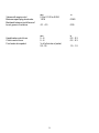
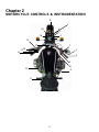
URAL Motorcycles
Owner’s Manual
2003 Model
Retro Solo
Irbit Motorworks of America Inc.
15411 NE 95th St
Redmond WA
98052
www.imz-ural.com
Introduction ............................................................................................................................................................. 5
Warnings, Cautions, Notes ....................................................................................................................................... 5
Chapter 1 Specifications
Specifications .......................................................................................................................................................... 7
Torque Specifications ............................................................................................................................................. 10
Conversions .......................................................................................................................................................... 10
Chapter 2 Motorcycle Controls & Instrumentation
Motorcycle Controls & Instrumentation ................................................................................................................... 11
Controls ................................................................................................................................................................ 12
Control Cable Adjustment ...................................................................................................................................... 16
Control Cable Maintenance ................................................................................................................................... 16
Speedometer ......................................................................................................................................................... 16
Chapter 3 Engine Operation
Engine Operation and Maintenance ........................................................................................................................
Pre-Trip Preliminaries ............................................................................................................................................
Starting the Engine .................................................................................................................................................
Operating Precautions ............................................................................................................................................
Running-In the New Motorcycle ............................................................................................................................
17
17
17
21
21
Chapter 4 Engine Design
Brief Description of Design & Maintenance ..........................................................................................................
Lubrication System ................................................................................................................................................
Fuel System ...........................................................................................................................................................
Ignition System ......................................................................................................................................................
Ignition Timing .......................................................................................................................................................
23
24
25
26
26
Chapter 5 Carburetors
Carburetors ........................................................................................................................................................... 29
Carburetor Maintenance ........................................................................................................................................ 30
Chapter 6 Power Transmission
Power Transmission ...............................................................................................................................................
Clutch ...................................................................................................................................................................
Gearbox ................................................................................................................................................................
Final Drive .............................................................................................................................................................
31
31
31
31
Chapter 7 Running Gear
Running Gear .........................................................................................................................................................
Spring-Loaded Hydrraulic Shock Absorber ...........................................................................................................
Front Fork ............................................................................................................................................................
Steering Head Bearings ..........................................................................................................................................
33
33
34
34
Chapter 8 Wheel & Tires
Wheels and Tires ................................................................................................................................................... 35
Tire Data ................................................................................................................................................................36
Wheel and Tire Maintenance ................................................................................................................................. 37
Chapter 9 Brakes
Brakes .................................................................................................................................................................. 39
Chapter 10 Electrical
Electrical Equipment .............................................................................................................................................. 43
Electrical Circuits.....................................................................................................................................................43
Electrical Equipment Maintenance .......................................................................................................................... 44
Electrical Wiring Diagram ....................................................................................................................................... 46
Chapter 11 Maintenance
Maintenance of Motorcycle ...................................................................................................................................
List of Recommended Lubricants ...........................................................................................................................
Lubrication Chart ...................................................................................................................................................
Required Lubrication .............................................................................................................................................
Care of Motorcycle Paint .......................................................................................................................................
Preservation and Storage .......................................................................................................................................
Battery ..................................................................................................................................................................
List of Individual Tool Set, Spare Parts, Accessories & Documents .........................................................................
47
47
48
48
48
49
50
51
Chapter 12 Safe Operating Rules
Safe Operating Rules ............................................................................................................................................. 53
Chapter 13 Warranty
Warranty Agreement ............................................................................................................................................. 55
Warranty Claim Form ........................................................................................................................................... 63
Flat Rate Schedule ............................................................................................................................................... 64
Chapter 14 Service Coupons
Service Coupons ................................................................................................................................................... 67
New Address Form ............................................................................................................................................... 77
New Owner Form ................................................................................................................................................. 78
URAL Starting and Running Tips .................................................................................................... Inside Back Cover
4
INTRODUCTION
Welcome to the URAL Motorcycling Family! Your Ural has been built by the Irbit Motorcycle Factory in
Russia and distributed by Irbit Motorworks of America, the United States affiliate of the Irbit Motorcycle
Factory. The Ural motorcycle conforms to all applicable US Federal Motor Vehicle Safety Standards and
US Environmental Protection Agency regulations effective on the date of manufacture.
This manual has been prepared to acquaint you with the operation, care and maintenance of your
motorcycle, and to provide you with important safety information. Follow these instructions carefully for
maximum motorcycle performance and for your personal motorcycling safety and pleasure.
Your Owner’s Manual contains instructions for operation, maintenance and minor repairs. Major repairs
require the attention of a skilled mechanic and the use of special tools and equipment. Your Authorized
IMWA Ural Dealer has the facilities, experience and genuine Ural parts necessary to provide this
valuable service.
Any suggestions or comments are welcome! Write to us or post an e-mail on the Ural Discussion
bulletin board at www.imz-ural.com.
Important Notice!
Statements in this manual preceded by the following words are of special importance:
Maintenance intervals recommended are based on operational experience under various climatic and
road conditions. However, these intervals may be extended or reduced following repeated checks of the
lubricant condition and general mechanical condition of the motorcycle.
Carefully study this Owner’s Manual before starting the motorcycle.
Specifications and design are subject to change without notice.
5
6
Chapter 1
SPECIFICATIONS
Retro
Maximum speed of motorcycle
Reference fuel consumption at 85% of
120 km/h 74 mph
14 km/L 33 mpg
Dry mass of motorcycle
Maximum load-carrying capacity
Noise level
680 lb.
400 lb.
below 80db
Length
Width
Height
Road Clearance
Seat height
Wheel base
2500 mm / 8 ft
1700 mm / 5 ft 6 in
1100 mm / 3 ft 6 in
125 mm / 5 in
840 mm / 33 in
1470 mm / 58 in
Type
Displacement
Cylinder bore
Piston stroke
Compression ratio :1
Rated horsepower
Rated rotational speed
Rated torque
Lubrication system
Lubricant
4 stroke, overhead valves, opposed twin-cylinder
745 cc
78 mm
78 mm
KW /
BHp
5600 RPM
3 ft.-lbs @ 3750 RPM
Dual system of forced lubrication and splashing
SAE 20W/50
Carburetor type
Number of carburetors
Air cleaner
Fuel
PCV Valve
32 CVK Keihin
2
Paper Filter Element
91 octane premium unleaded gasoline
Internal Breather
7
Ignition system
Ignition coil
Spark plugs
Ignition timing
Alternator
Battery
Headlight
135.3734.COM-2 (CDI)
135.3705-2
NGK BP7H
Automatic spark timer
35 amp / 12 Volt
Interstate #Y or equivalent
Sylvania Halogen 6024, 7" round sealed beam
Clutch
Gearbox
Dry double-disk clutch
4 speed gearbox with reverse gear lever
I gear
II gear
III gear
IV gear
Reverse gear
3.6
2.28
1.5
1.19
4.
Speedometer drive ratio
Final drive ratio
0.4
Fuel tank
Reserve
Engine
Transmission
Final drive oz / ml
Shock Absorbers 3.5 oz
5 Gal / 19L
.5 Gal / 2L
68 oz / 2L
oz / L
FrameTubular welded
Rear wheel suspension
Front fork
Brakes
Tires1
Swing arms with spring shock absorbers
Telescopic
Hydraulic Disk on front, Hydraulic Drum on rear
”
Front 22 psi cold (1.5 Bar / 150 kPa) Front 22 psi cold
Rear 36 psi cold (2.5 Bar / 250 kPa) Rear 36 psi cold
8
Valves with engine cold
Between spark plug electrodes
Backlash between tooth faces of
bevel gears in final drive
Hand brake control lever
Clutch control lever
Foot brake drive pedal
mm
0.5 to 0.1.00 to 0.004
1.016
0.040
0.1 - 0.3
0.00
mm
5-8
5-8
¼ of full stroke of pedal,
25 - 30
in
0.2 - 0.3
0.2 - 0.3
9
in
1.0 - 1.2
TORQUE SPECIFICATIONS
Metric
54 to 61 Nm
237 to 251 Nm
19 to 30 Nm top
38 to 49 Nm bottom
30 to 35 Nm
30 to 35 Nm
to 1 Nm
to 1
Nm5 ft/lb to
14 to 19 Nm
68 to 90 Nm
22 to 27 Nm
19 to 22 Nm
136 to 163 Nm
US Equivalent
40 ft/lb to 45 ft/lb
175 ft/lb to 185 ft/lb
14 ft/lb to 22 ft/lb
28 ft/lb to 36 ft/lb
22 ft/lb to 26 ft/lb
22 ft/lb to 26 ft/lb
ft/lb to ft/lil pump bolt
ft/lngine sump
10 ft/lb to 14 ft/lb
50 ft/lb to 66 ft/lb
16 ft/lb to 20 ft/lb
14 ft/lb to 16 ft/lb
100 ft/lb to 120 ft/lb
Location on Bike
cylinder heads
fly wheel tightening screws
shock absorber
shock absorber
bearing nut
final drive to swing arm bolts
final drive case nuts
nut fastening the pinion bearing
reverse gear brake lever
alternator gear nut
steering stem nut
CONVERSIONS
To convert from mm to in, divide by 25.4 (there are 25.4 mm per inch).
To convert from liters to gallons, divide by 3.785 (there are 3.78 liters per gallon).
To convert from liters to quarts, multiply by 1.056 (there are 1.056 quarts per liter).
To convert from liters to pints, multiply by 2.112 (there are 2.112 pints per liter).
To convert from km to miles, multiply by .62 (there is .62 mile per km).
To convert from km/hr to mph, multiply by .62.
To convert from Newton-meter (Nm) to inch-pound, multiply by 8.86.
To convert from Newton-meter (Nm) to foot-pound, multiply by .7376.
To convert from cm3 (cc) to pints, divide by 473 (there are 473 cc per pint).
To convert Celcius to Fahrenheit: F = C x 1.8 + 32.
To convert Fahrenheit to Celcius, C
F
32 divide by 1.8.
10
Chapter 2
MOTORCYCLE CONTROLS & INSTRUMENTATION
19
20
2
3
4
18
1
16
17
14
13
7
15
5
6
8
10
12
9
11
Controls and Instrumentation
11
Clutch Control Lever
Clutch Control Lever
Front Brake Control Lever
Clutch control lever When the clutch lever is squeezed, the engine is disengaged from the
gearbox. When the lever is released, the engine and gearbox are connected.
Caution:
Front brake control lever When the lever is squeezed, the front wheel brake is actuated. The
front brake should be used together with rear brake. When the brake lever is squeezed, the stop
signal lights are switched on.
12
Kick starter is designed to start the engine. On pressing the lever, the crankshaft of the engine is
rotated via the gearbox. The lever is returned to its initial position by a spring inside the gearbox.
Gear shift lever
Kick Starter
Reverse Gear Selector
Gear shift Lever. When the front pedal is pressed, shifting from higher to lower gear takes place.
When the rear pedal is pressed, shifting from lower to higher gear takes place. The neutral
position is fixed between the 1st and 2nd gears. It is important to shift smoothly with a constant force
and not to kick the gear shift pedal.
Reverse gear is engaged by pushing forward on the reverse gear selector. Reverse gear should
only br engaged from neutral or 1st gear, after the motorcycle has come to a complete stop. When
the reverse gear selector is pulled backward, the transmission will be in neutral.
IMPORTANT! The green pilot lamp will illuminate when the transmission is in neutral or
reverse gear. (see “Starting the Engine”).
13
Ignition Switch has three fixed positions of the key.
The positions of the ignition are shown above.
Off
Run
Parking
All electrical systems are off.
Voltage is supplied to all electrical systems.
Voltage is supplied to running lights only.
Ignition
Switch
Turn Signal
Alternator
Trip
Odometer
High
Beam
Neutral
Indicator
The indicator lamps are located on the instrument panel:
14
Engine Cutoff
Switch
Electric Start
Switch
Headlight
Hi / Low Beam
Switch
Turn Signal
Switch
Horn
Switch
15
CONTROL CABLE ADJUSTMENT
The control cables are adjusted by screw adjustments at the cable ends.
With the control levers released:
for the clutch a play at the clutch lever end should be equal to 5 - 8 mm/0.2 - 0.3 in.
for the carburetors - carburetor throttle cables synchronized
With the control levers (handles) fully depressed:
for the clutch — complete disengagement of the engine from the transmission; noiseless shifting
of gears means good adjustment of the clutch cable.
for the carburetors — lift of throttles to the maximum and equal height
CONTROL CABLE MAINTENANCE
The daily preventative maintenance involves checking the functioning, condition and fastening of
the tie rods, cables and braking action. Refer to the Service Coupons for lubrication schedule.
As per the service coupons, lubricate the throttle control twist grip, the lever pins and ends of
cables used in the clutch and the throttles.
SPEEDOMETER MAINTENANCE
After every 10,000 km, remove the speedometer from the motorcycle and add five or six drops of
oil into the speedometer where the cable inserts into the speedometer. This will lubricate the speedometer internally.
To lubricate the speedometer cable, remove the cable from the speedometer and pull straight. Use
speedometer lubricating oil or light machine oil.
16
Chapter 3
ENGINE OPERATION
PRE-TRIP PRELIMINARIES
Pre-Trip Check List
1.
2.
3.
4.
5.
Check all lights and the horn for proper operation.
Check the brake and clutch levers and/or pedals.
Make sure all wheels and the final drive assemblies are securely fastened .
Check the carburetor flanges and air filter ducts for integrity and proper alignment.
Check the tire tread depth - should be greater than 1/8 inch.
Gasoline level in the fully filled tank should be 10 - 15 mm / ½ - ¾ in. below the lower edge of the
tank filler. Do not overfill the tank.
See that the oil level in the engine crankcase is not higher than the top and not lower than the
bottom marks on the dipstick with the filler plug undone. (See chapter 4 Lubrication System)
STARTING THE ENGINE
When the ignition is switched on, the green & red lamps on the instrument panel should
illuminate. This will indicate that the battery is discharging while the engine is not running and that
the motorcycle is in neutral.
17
Prime Position
Fuel On
Position
Reserve Fuel
Position
1. When starting the engine after the motorcycle has been parked for an extended period of
time, or after the fuel tank and/or carburetors have been completely emptied of gasoline
(e.g. due running out of fuel, evaporation, or installation of replacement parts), set the valve
to the “PRI” (Prime) position. This would allow gasoline to fill the float chambers of the
carburetors and prepare the engine for starting.
2. Start the engine
3. After the engine starts, set the valve to the “ON” position and keep the valve in this position
for regular use of the motorcycle. (When set to “ON”, the valve is automatically activated
when the engine starts and stops, opening and shutting off the supply of fuel to the
carburetors)
4. After using up the main volume of fuel (engines starts stalling due to lack of fuel), set the
valve to the “RES” (Reserve) position and continue driving. After refueling, remember to set
the valve back to “ON” to avoid running out of fuel completely.
The carburetor enricheners provide extra fuel to the mixture. This extra fuel will allow a cold engine
to start and run until it has warmed up sufficiently to allow normal operation. Use caution when
using the enricheners, as they can easily cause the engine to flood, or foul the spark plugs. The
enricheners should only be left on as long as necessary to keep the engine running while cold and
should be turned off as soon as possible.
Depending on the engine and ambient temperature, use the carburetor enricheners and starting
procedure as follows:
18
Enrichener off
Enrichener on
Manual Starting (without electric starter)
1. Turn on the ignition and depress the kick lever about 1/4 of its travel (enough to firmly get
the ball of your foot on the lever) with either your left foot or right foot, depending on what
position is most comfortable with your right hand on the throttle. Take up the slack in the
throttle until you can feel some slight resistance from the return springs in the carburetors,
without any advance on the throttle, since this may flood the engine.
2. Give the kick lever a swift kick. When the engine starts, tickle the throttle (quickly increase and decrease it) to keep the engine running, but not too fast. If the engine doesn’t
start, repeat the kicking procedure. A properly adjusted warm engine should start within a
few kicks. If the engine doesn’t start, try the procedure described below in item
3. If it still doesn’t start or fire, it may be flooded.
the
engine and the spark plugs may become fouled with gasoline.
Electric Starting
1. Set carburetor enricheners as with kick starting. Unlike manual starting, however, the
gearbox does not have to be in neutral as the electric starter may be engaged with the clutch
lever pulled in, or with the gearbox in neutral. Make sure the Ignition Cutoff Switch is set to
“ Ignition On” and push the starter button to turn over the engine.
2. When the engine has been standing for several hours but the ambient temperature is
high (60°F/15°C degrees or above), try starting it without any enricheners. If it doesn’t fire,
then use the procedure described below.
19
3. When the engine is cool or cold and the ambient temperature is between40°F-60°F/5°C15°C, engage both enricheners to start. As soon as the engine starts, immediately retract
the enricheners. Run the engine at moderate speed for 30-60 seconds. If it starts to die,
blip the twist grip throttle (rapidly twist part way towards full throttle and then back off) to keep
the engine running. After 1 to 3 minutes, depending on ambient temperature, the engine
should run smoothly without “blipping” the throttle.
4. If the engine is cold and ambient temperature is below 40°F, first, give the engine 5-10
(depending on how cold it is) priming kicks with the ignition off. This will get some oil
circulated to key internal parts. Engage the enricheners on both carburetors. The engine
should
then fire, depending on how cold it is. For example, when the ambient temperature is 0°F, it
typically takes about 5-10 rotations to start the engine. As soon as the engine starts, retract
both enricheners (after a few seconds).
When the engine is hot, do not choke or enrichen the carburetors. To do so risks flooding the
engine.
To start an engine that is flooded, first open the throttle fully, hold it there and give the engine up
to 10 swift kicks. If it still doesn’t fire, take the spark plugs out to see if they are wet with
gasoline. If they are wet, dry them. Clear excess gasoline from the cylinders by kicking the
engine over 10 times with the plugs out and the throttle closed. Then replace the plugs and
repeat the starting procedure described at the beginning of this section (1).
Additional Warnings: Once the engine starts, do not allow it to run at a high speed as this could
cause abnormal wear of the parts and may lead to seizure of the piston pin and pistons in the
cylinders since cold oil flows through the oil ducts with difficulty and fails to ensure sufficient
lubrication. A correctly adjusted warm engine should run steadily at low speed with the throttle
control
twist grip fully closed.
Do not let the motorcycle sit at idle for more than three minutes, as overheating could result.
20
OPERATING PRECAUTIONS
To move the motorcycle from rest, shift to 1st gear only. Avoid releasing the clutch suddenly,
because the engine is liable to stall or the motorcycle will start with a jerk. Do not drive the
motorcycle at speeds below the recommended speeds with the 2nd, 3rd or 4th gears engaged. It is
not advisable to use the 1st and 2nd gears for a long time, unless so required by road conditions.
RUNNING IN THE NEW MOTORCYCLE
The running-in period for the motorcycle is the first 1,500 km.
There are no special procedures that must be followed, but during the running-in period, a new
motorcycle requires the most careful attention. In the course of this period, do not overload the
machine. Avoid traveling on freeways and climbing steep hills. Do not race the engine or overheat
it at any time. Vary the throttle setting frequently, so as to avoid constant RPMs. Allow the new
engine frequent rest periods for cooling down.
When operating the Ural motorcycle on the highway, please try not to run continuously at speeds
above 65mph. If it is necessary to drive at speeds of 65mph and above let the engine cool by
running at a reduced speed for 10 - 15 minutes every 30 minutes if possible, this will provide longer
engine life.
When descending a long, steep grade, downshift and use engine compression together with
intermittent application of both brakes to slow the motorcycle. Avoid continuous use of brakes to
reduce overheating of the brakes and reduced efficiency.
While using the motorcycle in summer, pay special attention to the condition of the tires. Keep
them inflated up to pressures specified in this manual.
21
22
Chapter 4
ENGINE DESIGN
The motorcycle is equipped with a two-cylinder four-stroke air-cooled engine. The opposed arrangement of cylinders in the horizontal plane is the outstanding feature of the motorcycle design
which ensures proper cooling and balancing of the crank gear. The engine valves are located in
the cylinder heads.
In summer, carefully observe the heating condition of the engine, power transmission units and the
running gear mechanisms. Under normal heating conditions of the engine, the temperature of the
cylinder heads should not be over 356°F-428°F/180°C-220°C.
During everyday preventive maintenance, clean the engine of mud and dust, paying special attention to the cooling fins as their fouling will impair the efficiency of the engine cooling. Check engine crankcase, cylinders and cylinder heads for oil and fuel leaks. Check carburetor to cylinder
head adapter for any cracks or leaks. Visually inspect the alternator for any oil leaks.
23
LUBRICATION SYSTEM
The motorcycle engine features a dual lubrication system, some parts are force-lubricated by
pressure built up by the oil pump, while others by splashing . A full-flow paper oil filter is provided
in the lubrication system to prolong the engine life.
Maintenance of lubrication system. During the daily inspection, check the oil level in the engine
crankcase and top off the oil if necessary. Warm up the engine before changing the oil. Drain
used oil from the engine and the oil filter cavity after having unscrewed the drain plug and filter
plug. Change oil filter at the intervals shown in the service coupons. Set the rubber sealing bushing into the filter and fit the filter with the bushing onto the adapter of plug, then screw the latter into
the front cover. Now screw in the plug. Fill the engine with 68 oz. oil, or until the top mark of the
dipstick is reached.
Let the engine run for 3 - 5 min. Check the oil level again adding oil up to the top groove of the
dipstick if needed. During motorcycle service, keep oil level in the engine crankcase close to the
top groove of the oil dipstick. Don’t ride the motorcycle if the oil level is below the lower mark of the
dipstick until sufficient oil is added to raise the oil level to the top mark.
Correct position to measure the oil level
Make sure that the dipstick is screwed down securely after checking the oil level.
24
FUEL SYSTEM
The fuel system includes the gasoline tank, the three position fuel valve with filter and two
carburetors.
Petcock Location
Petcock
Fuel valve (petcock). The top threaded portion of the valve is screwed into the gasoline tank. The
petcock is of an automatic shutoff design. Vacuum from the engine opens the valve when the
engine is running. When the engine is stopped and looses vacuum, the petcock automatically
shuts off.
Fuel system maintenance. Before a trip, check the tightness of gasoline piping joints, & proper
functioning of throttle cables.
25
IGNITION SYSTEM
The ignition system incorporates the power supplies, ignition coil, Hall Effect pickup, electronic
module, two spark plugs, a set of low and high voltage wires and the ignition switch.
The ignition system will provide the spark to the spark plugs from 200 to 6000 RPM. With the
engine at rest, the ignition system will draw 100 mA. With the engine running, the ignition system
will draw 1.5 Amps. The operating voltage for the ignition system ranges between 7 to 16 Volts.
The electronic ignition system will automatically provide the required changes in timing to an accuracy of within + 1°.
Ignition coil The ignition coil has two high voltage terminals, each supplying one of the cylinder
spark plugs and operating in conjunction with the Hall Effect pickup.
Periodically, check all wires in the ignition system to be sure they aren’t crimped or have loose
connections. Loose connections will cause erratic performance and poor fuel economy.
Spark plugs. In certain situations, spark plugs can quickly foul with carbon or soot. The plugs can
be cleaned but it is easier to put in a new set of plugs when on the road. We recommend that you
purchase an extra set of these plugs from your Authorized Ural Dealer and carry them in the motorcycle at all times.
Functioning of ignition system. Both plugs fire simultaneously on the left and right-hand cylinders, one spark being formed when the compression stroke terminates in one of the cylinders and
the other during the exhaust stroke.
IGNITION TIMING
To set the ignition timing, proceed as follows:
-Match the first mark on the flywheel with the center marks on the engine flywheel window.
-Loosen the fastening screws of the microprocessor unit and turn it counterclockwise until it stops.
-Apply power to the ignition system by switching the ignition on.
-Slowly turn the ignition unit clockwise, (the LED should be on)
-Stop turning the microprocessor unit when the LED turns off.
-Tighten the fastening screws of the microprocessor unit and switch the ignition off.
26
28
Chapter 5
CARBURETORS
32mm CVK Keihin Seike carburetors are used on of the Ural motorcycle. They are preset with
fixed mixture jetting and adjust automatically for altitude variations. This is due to the vacuum activation mechanism of these constant velocity type carburetors. Be sure to check the condition of all
carburetor adapters and air pipes every time before riding. If the carburetor flanges are in need of
replacement, use only genuine Ural replacement or Ural recommended parts.
Flange
Carburetor
29
Branch Pipe
CARBURETOR MAINTENANCE
The carburetors will require the sediment in the float bowls be drained periodically. This will ensure
that any contaminants that have accumulated in the float bowls do not enter the main or idle jets of
the carburetors. The fuel can be drained by opening the drains provided on the bottom of the float
bowls.
The fuel filters should also be changed every 10,000 km or when they appear to be dirty or not
flowing fuel correctly. Changing the filters will ensure that clean fuel is provided to the carburetors
and that there is no fuel starvation.
The carburetor to cylinder head adapters should be checked for leaks and cracks every trip. Failure of the adapters will cause the carburetor fuel mixture to become lean and cause internal damage to the engine.
30
Chapter 6
POWER TRANSMISSION
The power transmission of the motorcycle is comprised of the clutch, gearbox, drive shaft and the
final drive.
CLUTCH
The clutch transmits torque from the engine to the gearbox. Disengage the engine from the gearbox during shifting of the gears and during braking to a stop. The clutch provides for smooth
starting of the motorcycle from rest, protects the power transmission parts against damage when
the engine speed or drive wheel speed is suddenly changed. The clutch is of dry double-disk
design. The clutch release mechanism is controlled by the lever on the left grip of the handle bar.
With the clutch lever released, the engine is engaged to the gearbox. When the clutch lever is
squeezed, the engine is disengaged from the gearbox. Use the clutch lever for starting from
rest and for gear shifting. Under conditions of heavy traffic, when gears frequently have to be
shifted, do not slip the clutch too much, as this will accelerate wear of the disks.
GEARBOX
Shifting the gears is best accomplished by pushing down on the front toe plate for first gear and to
downshift from higher gears. To shift up into second, third and fourth gear, use the front toe plate
and push upwards quickly and firmly. Since the Ural transmission is a non-synchronized design, it
is very important that the clutch be used when shifting. Not using the clutch when shifting can
cause damage and void the warranty.
FINAL DRIVE
Maintenance of propeller shaft splines and final drive.
Remove the final drive from the swing arm and pull the final drive towards the rear of the bike.
When the drive shaft is free, coat the drive shaft splines with grease. At the same time, use a
grease gun to force grease into the drive shaft universal joint.
Typical final drive maintenance includes tightening the nuts which fasten the final drive to the
swinging fork arm. Failure to tighten the nuts may result in loose joints and the destruction of the
final drive cover. Change the final drive oil as determined by the service coupons. Undo the filler
and drain plugs and drain the used oil. Reinsert the drain plug and fill the casing with fresh 20w /
50 Castrol oil and flush the final drive by turning the rear wheel several times. Drain the 20w / 50
31
Castrol oil and then refill the final drive with the specified lubricant. Reinsert the upper fill plug and
wipe off any excess or spilled oil from the final drive.
Filler Plug
Universal Joint
Splines
Drain Plug
Final Drive Assy
Rear Universal Joint
32
Chapter 7
RUNNING GEAR
SPRING LOADED HYDRAULIC SHOCK ABSORBER
The suspension features cam-type adjusters used for varying the pretension of the supporting
springs to suit the load and the road condition. The degree of tension of the springs is adjustable
allowing two positions. The first (lower) position corresponds to the load due to the motorcycle’s
own weight and the driver’s. the second (upper) position of moving cam corresponds to the maximum load.
Care of shock absorbers. Fill the shock absorber with 105 cm³ of hydraulic fluid. Each time
during maintenance, check the bolts fixing the top and bottom ends of the shock absorbers for
tightness.
33