1
Lists
1
2
System Overview / Operating Elements
3
System Operation
4
5
Operator Manual
Volume 2
Examination
6
Image Viewing and Image Processing
7
Special Examinations
8
9
AXIOM Artis
Systems for Angiocardiography,
Angiography, Neuroradiology,
Interventional Procedures and
General Diagnostics
Artis VB30B and higher
(syngo® VD30C and higher)
Exam Sets
10
Quantification
11
Accessories and Auxiliary Devices
12
13
© Siemens AG 2004
All rights reserved
Order No.: AXA4-100.620.08.01.02
01.2006
Contact Information:
Siemens AG
Siemens AG, Medical Solutions, AX
Wittelsbacher Platz 2
Siemensstrasse 1
DE-80333 Muenchen
DE-91301 Forchheim
Germany
Germany
Phone: +49 9191 18-0
Internet: www.Medical.Siemens.com
Troubleshooting
14
15
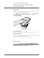
Important information from the
manufacturer
This product is provided with a CE marking in accordance with the
regulations stated in Appendix II of the Directive 93/42/EEC of June
14th, 1993 concerning medical devices.
In accordance with Appendix IX of the Directive 93/42/EEC, this
device is assigned to class II b.
The CE marking applies only to medical devices which have been
put on the market according to the above-mentioned EC Directive.
Unauthorized changes to this product invalidate this declaration.
Please observe the Operator Manual Volume 1.
Important information is given there.
The original version of this manual was written in English.
AXIOM Artis
Overall Table of Contents
Operator Manual
Lists
Overall Table of Contents
Part: Lists
Chapter: Overall Table of Contents ....................................................................................................... 1
Chapter: Index ............................................................................................................................................. 7
Chapter: Abbreviations/Glossary .......................................................................................................... 33
Part: System Overview / Operating Elements
Chapter: Introduction ................................................................................................................................. 5
Application ............................................................................................................................................ 5
System configurations .......................................................................................................................... 5
Chapter: Equipment in the Control Room ........................................................................................... 7
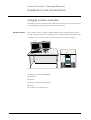
Imaging system overview ..................................................................................................................... 7
On-site equipment .............................................................................................................................. 17
Chapter: Equipment in the Examination Room ............................................................................... 19
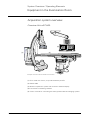
Acquisition system overview .............................................................................................................. 19
Chapter: Operating Elements and Displays in the Examination Room..................................... 31
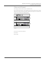
Control consoles ................................................................................................................................. 31
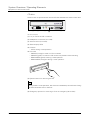
Keys on the FD ................................................................................................................................... 43
Handswitch ......................................................................................................................................... 44
Footswitch .......................................................................................................................................... 44
Manual control for table with lateral tilt .............................................................................................. 50
Monitor suspension system ............................................................................................................... 50
Data display ........................................................................................................................................ 54
Voice control units .............................................................................................................................. 65
Acoustic signals .................................................................................................................................. 67
"Plane ready for radiation" displays ...................................................................................................... 68
Part: System Operation
Chapter: Unit Movements ....................................................................................................................... 5
Movement possibilities ......................................................................................................................... 5
AXIOM Artis
AXA4-100.620.08.01.02
1 / 36
AXIOM Artis
Overall Table of Contents
Basic positions of the units ................................................................................................................. 10
Initiating unit movements ................................................................................................................... 14
Chapter: Image Format, Collimation and Filtration ......................................................................... 57
Selecting the image format/zoom stage ............................................................................................. 57
Setting the collimators ........................................................................................................................ 59
Grid ..................................................................................................................................................... 68
Chapter: Operation via Touchscreen Control ................................................................................... 71
Introduction ......................................................................................................................................... 71
Command inputs on the touchscreen control ..................................................................................... 71
Chapter: Operation via Voice Control ................................................................................................. 81
Important information ......................................................................................................................... 81
Setup for operation ............................................................................................................................. 82
Voice commands ................................................................................................................................ 83
Chapter: DVD Video Recording ............................................................................................................ 89
Important information ......................................................................................................................... 89
DVD recording ..................................................................................................................................... 90
DVD playback ...................................................................................................................................... 93
Part: Examination
Chapter: Preparing the Examination - Fluoroscopy - Acquisition .................................................. 3
Registering a patient ............................................................................................................................. 3
Preparing the patient and equipment .................................................................................................... 9
Task cards for the examination ........................................................................................................... 13
Parameters for the examination .......................................................................................................... 19
General information about fluoroscopy/acquisition ............................................................................. 38
Fluoroscopy ........................................................................................................................................ 43
Acquisition .......................................................................................................................................... 47
Chapter: Reference Images and Display Modes............................................................................. 49
Storing reference images .................................................................................................................... 50
Display modes for fluoroscopy/roadmap and acquisition .................................................................... 52
Selecting the image source for the additional color display ................................................................ 58
Chapter: Subtracted Fluoroscopy: Roadmap ................................................................................... 59
Introduction ......................................................................................................................................... 59
Performing roadmap ........................................................................................................................... 60
2 / 36
AXA4-100.620.08.01.02
Operator Manual
AXIOM Artis
Overall Table of Contents
Part: Image Viewing and Image Processing
Chapter: General ......................................................................................................................................... 5
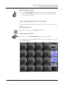
The task card PostProc ......................................................................................................................... 5
Starting postprocessing ...................................................................................................................... 11
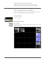
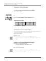
Chapter: Managing and Viewing Scenes/Images ........................................................................... 19
The scene directory of a patient ......................................................................................................... 19
The image directory of a scene ........................................................................................................... 23
Viewing scenes/images ...................................................................................................................... 24
Chapter: Image Postprocessing ........................................................................................................... 41
Introduction ......................................................................................................................................... 41
Defining window and filter values ....................................................................................................... 42
Changing the image display ................................................................................................................ 49
Adding text and graphics to images .................................................................................................... 51
Chapter: DSA Postprocessing .............................................................................................................. 71
Introduction ......................................................................................................................................... 71
DSA tools ............................................................................................................................................ 72
Chapter: Exam Protocol .......................................................................................................................... 93
Displaying the Exam Protocol ............................................................................................................. 93
Chapter: Closing Postprocessing ....................................................................................................... 101
Automatic storage ............................................................................................................................. 101
Storing the current image (Store Monitor) ........................................................................................ 101
Documenting scenes/images ........................................................................................................... 102
Closing the patient ............................................................................................................................ 107
Procedure tracking with MPPS ......................................................................................................... 109
Deleting patients/studies/series/scenes ........................................................................................... 111
Part: Special Examinations
Part: Exam Sets
Chapter: The Exam Set Editor ................................................................................................................ 3
Introduction ........................................................................................................................................... 3
Managing and editing exam sets .......................................................................................................... 5
Chapter: Parameters for Exam Sets ................................................................................................... 17
Acquisition parameters ....................................................................................................................... 18
Parameters for fluoroscopy/roadmap .................................................................................................. 32
General parameters ............................................................................................................................ 38
AXIOM Artis
AXA4-100.620.08.01.02
3 / 36
AXIOM Artis
Overall Table of Contents
Part: Quantification
Chapter: General ......................................................................................................................................... 5
Quantitative analysis methods .............................................................................................................. 5
Important notes .................................................................................................................................... 6
The Quant task card .............................................................................................................................. 7
General postprocessing functions ...................................................................................................... 10
Documenting images and reports ....................................................................................................... 17
Default settings ................................................................................................................................... 20
Chapter: Calibration ................................................................................................................................. 23
Introduction ......................................................................................................................................... 23
Performing a calibration ...................................................................................................................... 25
Configuring the calibration .................................................................................................................. 40
Chapter: Quantitative Vascular Analysis (QCA, QVA) .................................................................... 43
Starting vascular analysis .................................................................................................................... 43
Artery contour detection ..................................................................................................................... 47
Calling up and entering information about the contour ....................................................................... 52
Performing analysis ............................................................................................................................. 58
Results (report) ................................................................................................................................... 65
Configuring QCA/QVA ......................................................................................................................... 71
Chapter: Quantitative Ventricular Analysis (LVA) ............................................................................ 73
Important notes .................................................................................................................................. 73
Starting analysis .................................................................................................................................. 73
Defining contours ................................................................................................................................ 81
Results (report) ................................................................................................................................... 89
Wall motion analysis ........................................................................................................................... 96
Configuring LVA ................................................................................................................................ 100
Bibliography on LVA .......................................................................................................................... 103
Part: Accessories and Auxiliary Devices
Chapter: General Information about Accessories ............................................................................. 5
Equipment with accessories ................................................................................................................. 5
Handling accessory parts ...................................................................................................................... 5
Chapter: Accessories for the Patient Table (not in Artis dMP)...................................................... 7
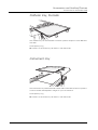
Tabletops .............................................................................................................................................. 7
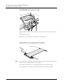
Mattresses ............................................................................................................................................ 7
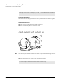
Head support with cushion set ............................................................................................................. 8
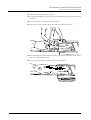
Supports with accessory rails ............................................................................................................... 9
Head-end holder ................................................................................................................................. 10
Articulated arm support ...................................................................................................................... 11
Handgrips with supports ..................................................................................................................... 12
Shoulder supports ............................................................................................................................... 14
4 / 36
AXA4-100.620.08.01.02
Operator Manual
AXIOM Artis
Overall Table of Contents
Arm support ........................................................................................................................................ 15
Arm holders ........................................................................................................................................ 16
Cable clips ........................................................................................................................................... 17
Infusion bottle holder .......................................................................................................................... 17
Immobilizing straps ............................................................................................................................. 18
Catheter tray, footside ........................................................................................................................ 19
Instrument tray ................................................................................................................................... 19
Stackable accessory rail ...................................................................................................................... 20
Abdominal compression band ............................................................................................................ 20
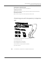
Positioning set with transparency compensation ............................................................................... 21
Chapter: Accessories for Artis (d)MP ................................................................................................. 25
Immobilizing straps ............................................................................................................................. 25
Holder with accessory rails ................................................................................................................. 26
Adapter with rails ................................................................................................................................ 28
Footboard ............................................................................................................................................ 30
Handgrips ............................................................................................................................................ 33
Shoulder belt ....................................................................................................................................... 34
Arm support ........................................................................................................................................ 35
Tabletop extension .............................................................................................................................. 36
Compression unit ................................................................................................................................ 37
Stirrups ............................................................................................................................................... 38
Foot holder .......................................................................................................................................... 40
Chapter: Miscellaneous Accessories .................................................................................................. 43
Accessories for the primary collimator ............................................................................................... 43
Accessories for radiation protection ................................................................................................... 44
Examiner lights ................................................................................................................................... 51
Injector ................................................................................................................................................ 52
Sterile covers ...................................................................................................................................... 53
Part: Troubleshooting
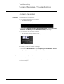
Chapter: System Messages / Troubleshooting ................................................................................. 3
System messages ................................................................................................................................ 3
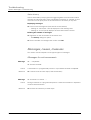
Messages, causes, measures .............................................................................................................. 8
AXIOM Artis
AXA4-100.620.08.01.02
5 / 36
AXIOM Artis
Overall Table of Contents
6 / 36
AXA4-100.620.08.01.02
Operator Manual
AXIOM Artis
Index
Operator Manual
Index
Part
Page
#
1:1 pixel display
3D-DYNAVISION
transferring data
Image Viewing and Image Processing
35
Image Viewing and Image Processing
107
A
Accessories
equipment
for Artis (d)MP
for radiation protection
for the patient table
for the primary collimator
handling
mattresses
miscellaneous
tabletop
Accessory rail
stackable
Accessory rails
supports
Acoustic signals
ACQ zoom
Acquisition
acoustic signals
display
display modes
parameters
storing as reference image
Acquisition button
Acquisition modes
Acquisition plane
selecting
selecting on the touchscreen
Acquisition program
changing
checking/changing
storing and/or applying
Action history
Active examination
Active patient
Adapter with rails
Additional color display
selecting the image source
Adults
grid
Analysis
centerline wall motion
performing in QCA/QVA
radial wall motion
regional wall motion
results of LVA
starting LVA
AXIOM Artis
Accessories and Auxiliary Devices
Accessories and Auxiliary Devices
Accessories and Auxiliary Devices
Accessories and Auxiliary Devices
Accessories and Auxiliary Devices
Accessories and Auxiliary Devices
Accessories and Auxiliary Devices
Accessories and Auxiliary Devices
Accessories and Auxiliary Devices
5
25
44
7
43
5
7
43
7
Accessories and Auxiliary Devices
System Overview / Operating Elements
Accessories and Auxiliary Devices
System Overview / Operating Elements
System Operation
Examination
System Overview / Operating Elements
Examination
Examination
Exam Sets
Examination
System Overview / Operating Elements
System Overview / Operating Elements
20
27
9
67
57
47
67
38
53
18
50
44
6
Examination
System Operation
31
76
Examination
Examination
Exam Sets
Troubleshooting
Exam Sets
Image Viewing and Image Processing
Accessories and Auxiliary Devices
29
28
14
8
6
11
28
Examination
58
System Operation
68
Quantification
Quantification
Quantification
Quantification
Quantification
Quantification
96
58
99
98
94
73
AXA4-100.620.08.01.02
7 / 36
AXIOM Artis
Index
Part
Analysis method
in LVA
selecting for LVA
selecting in QCA/QVA
Anatomical background
fading in
with roadmap
Aneurysms
Angio collimator
control module
Angle
changing
display
Angle of stand swivel
display
Angles
drawing and measuring
Angul. Step
Dyna parameter
Angulations
CRAN/CAUD
LAO/RAO
Annotation
Aortic aneurysms
Aortic valve
in LVA
Apex
in LVA
Application
Area
results in QCA/QVA
Area curve
in QCA/QVA
Area dose product
Area formula
results in QCA/QVA
Area length method
Arm holders
Arm support
Arrows
drawing
Arterial segment
selecting in QCA/QVA
Artery contour detection
in QCA/QVA
Articulated arm support
Artis (d)BA
overview
Artis (d)FC
overview
Artis (d)MP
accessories
overview
Artis (d)TC
overview
Auto
Dyna parameter
Auto ISO calibration
Auto Window
acquisition parameter
fluoroscopy parameter
Auto Windowing
Automap
8 / 36
Page
Quantification
Quantification
Quantification
101
74
44
Image Viewing and Image Processing
Examination
Quantification
78
64
64
System Overview / Operating Elements
39
Image Viewing and Image Processing
System Overview / Operating Elements
69
58
System Overview / Operating Elements
57
Image Viewing and Image Processing
68
Exam Sets
System Operation
System Operation
System Operation
Image Viewing and Image Processing
Quantification
31
30
30
30
55
64
Quantification
Quantification
81,
85
Quantification
System Overview / Operating Elements
81
5
Quantification
67
Quantification
Accessories and Auxiliary Devices
55
43
Quantification
Quantification
Accessories and Auxiliary Devices
Accessories and Auxiliary Devices
Accessories and Auxiliary Devices
67
92
16
15,
35
Image Viewing and Image Processing
61
Quantification
47
Quantification
Accessories and Auxiliary Devices
47
11
System Overview / Operating Elements
21
System Overview / Operating Elements
19
Accessories and Auxiliary Devices
System Overview / Operating Elements
25
28
System Overview / Operating Elements
23
Exam Sets
Image Viewing and Image Processing
Quantification
31
63,
23
Exam Sets
Exam Sets
Image Viewing and Image Processing
System Operation
24
35
43
44
AXA4-100.620.08.01.02
Operator Manual
AXIOM Artis
Index
Part
Automatic contour detection
in LVA
in QCA/QVA
Automatic error correction
Automatic isocenter calibration
Automatic restart
Available storage capacity
monitoring
Average
in calibration
Averaging
AXIOM Artis
AXIOM Sensis
Page
Quantification
Quantification
Troubleshooting
Quantification
Troubleshooting
81
48
18
27
18
Examination
41
Quantification
Image Viewing and Image Processing
Exam Sets
Lists
Examination
26
90,
38
33
18
Quantification
57
Quantification
57
System Operation
System Operation
10
10
B
Background analysis
in QCA/QVA
Background curves
in QCA/QVA
Basic positions
of the units
stopping
Bibliography
in LVA
Biplane
examination
postprocessing
quantification
roadmap
Biplane Head Side
position
Biplane Left Side
position
Biplane LVA
Biplane Pulse Reduction
fluoroscopy parameter
Biplane simultaneous angulation
key
Bolus Time
Dyna parameter
Bones White
acquisition parameter
Brakes
overcoming
releasing brakes for table
Brightness
monitor
BSA
Bypass fluoroscopy
display
emergency operation
Quantification
103
Examination
Image Viewing and Image Processing
Quantification
Examination
14
6
8
62
System Operation
13
System Operation
Quantification
13
79
Exam Sets
36
System Overview / Operating Elements
38
Exam Sets
31
Exam Sets
25
System Operation
System Operation
50
25
System Overview / Operating Elements
Quantification
9
95
Troubleshooting
Troubleshooting
14
14
Accessories and Auxiliary Devices
17
Quantification
72
C
Cable clips
Calculation
in QCA/QVA
AXIOM Artis
AXA4-100.620.08.01.02
9 / 36
AXIOM Artis
Index
Part
Calibration
configuring
in LVA
in QCA/QVA
performing
Quantification
using the table-object distance
with a calibration factor
Calibration factor
Calibration methods
Card collimator
control module
Cardiac
profile
Cardiac frequency
in LVA
Cardio Pulmonary Resuscitation
moving to a position
Cardiology
measuring field
CAREPOSITION
C-arm
basic positions
joystick
movements
moving
overview
positioning longitudinally
C-arm control module
keys
C-arm orbital movements
C-arm position
display
C-arm rotations
Cathcor
accepting patient data
Catheter calibration
method
Catheter sizes
Catheter tray
Causes
of errors messages
CD
drive
Centerline wall motion
in LVA
Circles
drawing
Click
Closing the patient
CM
Collimation
resetting
without radiation
Collimator
joystick
resetting
setting without radiation
10 / 36
Page
Quantification
Quantification
Quantification
Quantification
Quantification
Quantification
Quantification
Quantification
Quantification
Image Viewing and Image Processing
Quantification
23
40
74
44
25
6
28
39
24
63,
23
System Overview / Operating Elements
39
Examination
25
Quantification
102
System Operation
40
Examination
Examination
32
24
System Operation
System Overview / Operating Elements
System Operation
System Operation
System Operation
System Overview / Operating Elements
System Overview / Operating Elements
System Operation
System Overview / Operating Elements
System Overview / Operating Elements
System Operation
10
36
7,
9
29
24,
29
35
36
37
30
System Overview / Operating Elements
System Operation
57
30
Examination
Quantification
Quantification
Quantification
Quantification
Accessories and Auxiliary Devices
7
24,
30
41
41
19
Troubleshooting
8
System Overview / Operating Elements
14
Quantification
96
Image Viewing and Image Processing
System Overview / Operating Elements
Image Viewing and Image Processing
Image Viewing and Image Processing
System Operation
System Operation
System Operation
System Operation
System Operation
System Operation
61
12
107
71
57,
58,
60
60,
65
66
System Overview / Operating Elements
System Operation
System Operation
40
65
66
AXA4-100.620.08.01.02
Operator Manual
AXIOM Artis
Index
Part
Collimator control module
keys
Collimator home
key
Collimator rotation
key
not correct
Collimators
setting
Collision
override
Collision computer
Collision protection
Collision protection bar
Collision sensors
Combined C-arm movements
Comfortable positioning
patient
Compensating filter
Compression band
abdominal
Compression unit
Configuring
calibration
LVA
QCA/QVA
Connectors
for control modules
patient table
Constant Time Mode
acquisition parameter
Contour
annotating in LVA
automatic in QCA/QVA
checking in LVA
defining in LVA
defining manually in LVA
manual in QCA/QVA
Contour correction
for LVA manual
in LVA
in QCA/QVA
Contrast
monitor
Contrast Medium
acquisition parameter
Contrast medium
maximum filling
Control console
connection
positioning
Control module
C-arm
collimator
imaging system
patient table
stand
Control modules
trolley
Control room
equipment
Cooling unit fault
Correction
acquisition parameter
AXIOM Artis
Page
System Overview / Operating Elements
System Overview / Operating Elements
39
41
System Overview / Operating Elements
41
System Overview / Operating Elements
Troubleshooting
41
29
System Operation
59
System Operation
System Operation
System Operation
System Operation
System Operation
System Operation
System Operation
18
15,
16
15
15
15
30
Examination
Accessories and Auxiliary Devices
9
43
Accessories and Auxiliary Devices
Accessories and Auxiliary Devices
20
37
Quantification
Quantification
Quantification
40
100
71
System Overview / Operating Elements
System Overview / Operating Elements
30
27
Exam Sets
27
Quantification
Quantification
Quantification
Quantification
Quantification
Quantification
87
48
86
81
83
49
Quantification
Quantification
Quantification
84
82
49
System Overview / Operating Elements
9
Exam Sets
Image Viewing and Image Processing
Exam Sets
Image Viewing and Image Processing
System Overview / Operating Elements
System Operation
System Operation
23
71,
23
88
31
21
23
System Overview / Operating Elements
System Overview / Operating Elements
System Overview / Operating Elements
System Overview / Operating Elements
System Overview / Operating Elements
36
39
42
33
36
System Overview / Operating Elements
30
System Overview / Operating Elements
Troubleshooting
7
30
Exam Sets
20
AXA4-100.620.08.01.02
11 / 36
AXIOM Artis
Index
Part
Covers
notes
sterile
CPR position
CRAN/CAUD
display
Crispy
fluoroscopy parameter
CT image
storing as reference image
Curves
naming in QCA/QVA
Page
Accessories and Auxiliary Devices
Accessories and Auxiliary Devices
System Operation
54
53
40
System Overview / Operating Elements
57
Exam Sets
35
Examination
51
Quantification
52
System Overview / Operating Elements
System Overview / Operating Elements
54
55
System Overview / Operating Elements
Exam Sets
Exam Sets
Exam Sets
52
39
25
35
Exam Sets
Exam Sets
System Operation
Examination
25,
35
15
3
Image Viewing and Image Processing
28
Quantification
Quantification
90
65
Examination
System Operation
56
5
Quantification
Quantification
System Operation
56
19
15
Quantification
Accessories and Auxiliary Devices
72
43
Quantification
Quantification
64
66
Quantification
System Operation
Image Viewing and Image Processing
54
57
71
System Overview / Operating Elements
System Operation
System Operation
37
44
49
Exam Sets
Exam Sets
29
30
Troubleshooting
System Overview / Operating Elements
13
13
D
Data display
readings
DCS
suspension system
DDO (Digital Density Optimization)
acquisition parameter
fluoroscopy parameter
DDO-Kernel
fluoroscopy parameter
Dead man's grip (DMG)
Default patient
Default setting
for dynamic image display
Definitions
in LVA
in QCA/QVA
Degree of fading in
setting in Overlay Ref
Degrees of freedom
Density profile
in QCA/QVA
Detailed report
Deviation movement
Diagrams
in QCA/QVA
Diamentor
Diameter
local
results in QCA/QVA
Diameter curve
in QCA/QVA
Digital Acquisition Zoom
Digital subtraction angiography
Direct position
keys
moving to
storing
Direction
DR-Scanning parameter
Peri parameter
Disk
full
Diskette drive
12 / 36
AXA4-100.620.08.01.02
Operator Manual
AXIOM Artis
Index
Part
Display
acquisition program
active fluoroscopy/acquisition
BYPASS FLUORO
ECG on/off
Fluoroscopy/Roadmap
image text on/off
in QCA/QVA
joystick on the image monitor
limiting
scene time on/off
Display modes
for acquisition
for fluoroscopy
for Roadmap
Displays
plane ready for radiation
programmed positions
values
Distance calibration
Distance line
changing
moving
Distances
drawing and measuring
Dominant
selecting
with zoom
Door contact
Dose
acquisition parameter
display
fluoroscopy parameter
monitoring
too low
Dose measuring chamber
Double-click
DR images
windowing
Drives
DR-Scanning
acquisition parameter
DSA
postprocessing
DSA images
windowing
Dyna Control
Dyna parameter
Dynamic image displays
DYNAVISION
acquisition parameter
Page
Examination
Examination
Troubleshooting
Image Viewing and Image Processing
Examination
Image Viewing and Image Processing
Quantification
System Operation
Image Viewing and Image Processing
Image Viewing and Image Processing
28
38
14
38
33
39
72
77
20
39
Examination
Examination
Examination
53
52
53
System Overview / Operating Elements
System Overview / Operating Elements
System Overview / Operating Elements
Quantification
Quantification
68
59
59
24,
33
Image Viewing and Image Processing
Image Viewing and Image Processing
Quantification
Image Viewing and Image Processing
68
68
41
67
Examination
System Operation
System Overview / Operating Elements
Troubleshooting
32
58
17,
24
Exam Sets
System Overview / Operating Elements
Exam Sets
Examination
Troubleshooting
Accessories and Auxiliary Devices
System Overview / Operating Elements
20
62
33
39
26
43
12
Image Viewing and Image Processing
System Overview / Operating Elements
42
13
Exam Sets
29
Image Viewing and Image Processing
71
Image Viewing and Image Processing
42
Exam Sets
Image Viewing and Image Processing
31
28
Exam Sets
31
Examination
Troubleshooting
Image Viewing and Image Processing
10
31
38
Quantification
Quantification
86
73
E
ECG
attaching
problems
switch display on/off
ED
switching over
ED (end diastole)
AXIOM Artis
AXA4-100.620.08.01.02
13 / 36
AXIOM Artis
Index
Part
ED image
defining
Edge Enhancement
acquisition parameter
fluoroscopy parameter
Edge enhancement
value range
EE-Kernel
fluoroscopy parameter
Electronic shutter
setting
Emergency operation
bypass fluoroscopy
Emergency patient
registering
renaming
Emergency power operation
continuous fluoroscopy
Emergency power supply
in the hospital
Emergency SHUTDOWN
switching on again
Emergency STOP button
on control modules
Entries
in the Exam Protocol
Equipment
in the control room
in the examination room
Error handling
ES
switching over
ES (end systole)
ES image
defining
EVE
acquisition parameter
fluoroscopy parameter
Exam Protocol
entries
Exam set
checking/changing
creating
current
deleting
editing
renaming
viewing
Exam Set Editor
calling up
Exam sets
parameters
Examination room
equipment
Examination-specific messages
Examiner light
14 / 36
Page
Quantification
77
Exam Sets
Exam Sets
Image Viewing and Image Processing
Exam Sets
Exam Sets
Image Viewing and Image Processing
24
34
47,
24,
34
47
Exam Sets
Exam Sets
25,
35
Image Viewing and Image Processing
32
Troubleshooting
14
Examination
Image Viewing and Image Processing
4
13
Troubleshooting
Troubleshooting
Troubleshooting
17
16
15
Troubleshooting
17
System Overview / Operating Elements
32
Image Viewing and Image Processing
94
System Overview / Operating Elements
System Overview / Operating Elements
Troubleshooting
7
19
4
Quantification
Quantification
86
73
Quantification
78
Exam Sets
Exam Sets
Image Viewing and Image Processing
Image Viewing and Image Processing
Exam Sets
Examination
Exam Sets
Exam Sets
Exam Sets
Exam Sets
Exam Sets
Exam Sets
Exam Sets
Exam Sets
25
35
93
94
3
26
9
4
10
8
10
6
3
5
Exam Sets
17
System Overview / Operating Elements
Troubleshooting
Accessories and Auxiliary Devices
19
4
51
AXA4-100.620.08.01.02
Operator Manual
AXIOM Artis
Index
Part
Page
F
Fault
in the primary collimator
restart
FD
cooling system
covers
keys
rotation
FD cooling system
problem
FD lift
membrane keys
FD-object distance
automatic adjustment
Feet first
Fill image
Filling
maximum
Filter
joysticks
storing positions
using
Filter diaphragms
Filtering
in Quant
Finger filter
key
setting
Finger filters
Fixed
acquisition parameter
Fixed frame rate
acquisition parameter
Flat detector
covers
Flipping
image
Floor stand
movements
overview
positions
swivel
Fluoroscopy
acoustic signals
changing the program
display
display modes
parameters
storing a scene
Fluoroscopy program
checking/changing
Fluoroscopy signal
resetting
Focus
acquisition parameter
Foot holder
Footboard
Footswitch
Footswitch control
for table with lateral tilt
Format collimation
incorrect
AXIOM Artis
Troubleshooting
Troubleshooting
System Overview / Operating Elements
Troubleshooting
Accessories and Auxiliary Devices
System Overview / Operating Elements
System Operation
28
18
6
25
54
43
39
Troubleshooting
System Operation
System Overview / Operating Elements
25
38
43
System Operation
Examination
Image Viewing and Image Processing
39
21
71
Image Viewing and Image Processing
88
System Overview / Operating Elements
System Operation
Image Viewing and Image Processing
System Operation
System Operation
Quantification
40
64
47
61
57
12
System Overview / Operating Elements
System Operation
System Operation
41
62
61
Exam Sets
26
Exam Sets
System Overview / Operating Elements
Accessories and Auxiliary Devices
27
6
54
Examination
Image Viewing and Image Processing
36,
49
System Operation
System Overview / Operating Elements
System Operation
System Operation
Examination
System Overview / Operating Elements
Examination
Examination
Examination
Exam Sets
Examination
5
20
11
37
43
67
34
38
52
32
45
Examination
33
Examination
46
Exam Sets
Accessories and Auxiliary Devices
Accessories and Auxiliary Devices
System Overview / Operating Elements
21
40
30
44
System Overview / Operating Elements
49
Troubleshooting
28
AXA4-100.620.08.01.02
15 / 36
AXIOM Artis
Index
Part
Frame rates
acquisition parameter
Framerate
acquisition parameter
Dyna parameter
Full-screen display
Page
Exam Sets
26
Exam Sets
Exam Sets
Exam Sets
Image Viewing and Image Processing
27,
29
32
24
Exam Sets
23
Exam Sets
Exam Sets
25
35
Quantification
11
Image Viewing and Image Processing
53
Image Viewing and Image Processing
Image Viewing and Image Processing
Image Viewing and Image Processing
52
41
60
Image Viewing and Image Processing
System Operation
System Operation
System Operation
34
68
70
70
Accessories and Auxiliary Devices
Accessories and Auxiliary Devices
System Overview / Operating Elements
Exam Sets
Examination
33
12
44
39
21
System Operation
Accessories and Auxiliary Devices
Accessories and Auxiliary Devices
System Overview / Operating Elements
11
8
10
62
G
Gain Correction
acquisition parameter
Gamma Correction
acquisition parameter
fluoroscopy parameter
Graphic processing
with IS joystick
Graphic tools
active/inactive
Graphics
general
postprocessing
switching off/on
Gray scale
inverting
Grid
inserting (FD)
removing (FD)
H
Handgrips
with supports
Handswitch
Harmonization
Head first
Head Side
position
Head support
Head-end holder
Heat Units
Help
in the case of an error
Hemo catheter size
in QCA/QVA
High-contrast fluoroscopy
acoustic signals
Holder
head-end
Holder with accessory rails
HU
display
Troubleshooting
3
Quantification
Exam Sets
System Overview / Operating Elements
72
33
67
Accessories and Auxiliary Devices
Accessories and Auxiliary Devices
10
26
System Overview / Operating Elements
62
I
Icons
in the status line
16 / 36
Troubleshooting
AXA4-100.620.08.01.02
6
Operator Manual
AXIOM Artis
Index
Part
Image
archiving/sending/exporting
filming
flipping
full screen
loading
magnifying by two
making it coincide with mask
moving
scrolling
selecting
selecting display
selecting in LVA
selecting in QCA/QVA
storing
viewing
Image brightness
Image contrast
Image directory
of a scene
Image display
changing
dynamic
postprocessing
selecting
Image format
selecting
Image monitor
joystick display
Image orientation
changing
Image parameters
for acquisition
for fluoroscopy
Image postprocessing
DSA
Image processing
postprocessing
Image quality
changes
Image text
switch display on/off
switching off/on
Image texts
free texts
predefined
Image viewing
Images
adding text and graphics
annotating
blurred
incorrect collimation
smaller than normal
too many
Imaging system
joystick
operating in the examination room
Imaging system UPS
Immobilization
patient
Immobilizing straps
AXIOM Artis
Page
Image Viewing and Image Processing
Image Viewing and Image Processing
Examination
Image Viewing and Image Processing
Image Viewing and Image Processing
Image Viewing and Image Processing
Image Viewing and Image Processing
Image Viewing and Image Processing
Image Viewing and Image Processing
Image Viewing and Image Processing
Image Viewing and Image Processing
Image Viewing and Image Processing
Quantification
Quantification
Image Viewing and Image Processing
Quantification
Image Viewing and Image Processing
Image Viewing and Image Processing
Image Viewing and Image Processing
104
102
36,
49
24
12
35
81
16
24
21
30
77
43
101,
18
24
43
43
Image Viewing and Image Processing
23
Image Viewing and Image Processing
Image Viewing and Image Processing
Image Viewing and Image Processing
Examination
System Operation
System Operation
49
28
41
54
57
57
System Operation
Image Viewing and Image Processing
Examination
Image Viewing and Image Processing
Image Viewing and Image Processing
77
56
36,
49,
58
Exam Sets
Exam Sets
Image Viewing and Image Processing
Image Viewing and Image Processing
Image Viewing and Image Processing
Image Viewing and Image Processing
22
34
41
71
5
41
Troubleshooting
23
Image Viewing and Image Processing
Image Viewing and Image Processing
39
60
Image Viewing and Image Processing
Image Viewing and Image Processing
Image Viewing and Image Processing
59
59
5
Image Viewing and Image Processing
Image Viewing and Image Processing
Troubleshooting
Troubleshooting
Troubleshooting
Troubleshooting
51
55
27
27
27
13
System Overview / Operating Elements
System Operation
Troubleshooting
42
71
15
Examination
Accessories and Auxiliary Devices
Accessories and Auxiliary Devices
9
18,
25
AXA4-100.620.08.01.02
17 / 36
AXIOM Artis
Index
Part
Index method
Infants
grid
Infrared sensors
Infusion bottle holder
Injector
Input field
Input format
display
key
InSpace
InSpace Reconstruction
Instrument tray
Intercom system
Invert
Iris collimation
Iris correction
Iris diaphragm
key
IS joystick
functions
switching over the function
ISO stop
ISO tilting
reverse Trendelenburg / Trendelenburg
Isocenter
coordinates
display
key
setting
stopping
Isocenter distance
Page
Quantification
95
System Operation
System Operation
Accessories and Auxiliary Devices
Accessories and Auxiliary Devices
System Operation
68
15
17
52
57
System Overview / Operating Elements
System Overview / Operating Elements
Examination
Examination
Image Viewing and Image Processing
Accessories and Auxiliary Devices
System Overview / Operating Elements
Image Viewing and Image Processing
System Operation
Exam Sets
57
41
17
17,
107
19
16
34
59
20
System Overview / Operating Elements
System Overview / Operating Elements
System Operation
System Operation
Quantification
System Operation
41
42,
78
78
10
24
System Operation
System Operation
System Overview / Operating Elements
System Overview / Operating Elements
System Overview / Operating Elements
Examination
System Operation
Examination
31
10
61
58
35
11
24
11
System Overview / Operating Elements
System Overview / Operating Elements
System Operation
System Overview / Operating Elements
System Operation
System Overview / Operating Elements
System Overview / Operating Elements
System Overview / Operating Elements
36
40
77
42
78
33,
34
36
Exam Sets
Exam Sets
Exam Sets
38
25
35
System Overview / Operating Elements
System Overview / Operating Elements
38
10
J
Joystick
C-arm
collimator, filter
display on the image monitor
imaging system
on the touchscreen
patient table
stand
K
K Factor
acquisition parameter
fluoroscopy parameter
Key
orientation
Keyboard
18 / 36
AXA4-100.620.08.01.02
Operator Manual
AXIOM Artis
Index
Part
Page
Keys
on the C-arm control module
on the collimator control module
on the FD
on the monitor suspension system
on the stand control module
on the table control module
System Overview / Operating Elements
System Overview / Operating Elements
System Overview / Operating Elements
System Overview / Operating Elements
System Overview / Operating Elements
System Overview / Operating Elements
37
41
43
54
37
35
Exam Sets
18
Exam Sets
20
Exam Sets
19
Exam Sets
20
Exam Sets
33
Exam Sets
22
Quantification
58
System Overview / Operating Elements
Examination
Image Viewing and Image Processing
System Overview / Operating Elements
Image Viewing and Image Processing
Image Viewing and Image Processing
Image Viewing and Image Processing
System Overview / Operating Elements
57
21,
94
61
57
58
57
8
System Operation
22
System Operation
System Operation
Quantification
Image Viewing and Image Processing
11,
12
5
57
Examination
50
Image Viewing and Image Processing
Examination
61
52
Troubleshooting
27
Quantification
55
Quantification
Quantification
64
54
System Overview / Operating Elements
35
System Overview / Operating Elements
58
System Overview / Operating Elements
57
kV
acquisition parameter
kV Dose
acquisition parameter
kV Filter
acquisition parameter
kV ms
acquisition parameter
kV Warning Level
fluoroscopy parameter
kV-Focus
acquisition parameter
L
Lambert-Beer
law
LAO/RAO
display
Lateral position
patient coordinates
Laterality
changing
entering
LCD monitor
LED
on the termination panel
Left Side
position
Left Ventricle Analysis
Left/right assignment
LIH
storing as reference image
Lines
drawing
Live FLUO/LIH
Live image
incorrect collimation
Local density
displaying
Local diameter
analysis in QVA
displaying
Lock for tabletop movement
key
Longitudinal position
display
Longitudinal stand position
display
AXIOM Artis
AXA4-100.620.08.01.02
19 / 36
AXIOM Artis
Index
Part
Loop
all scenes
controlling
display mode
in LVA
Lower body radiation protection
LVA
configuring
important notes
LVA biplane
Page
Image Viewing and Image Processing
Examination
Image Viewing and Image Processing
Image Viewing and Image Processing
Examination
Quantification
Accessories and Auxiliary Devices
Quantification
Quantification
Quantification
Quantification
Quantification
28
53,
29
25
53
86
44
5,
73
100
73
5
Exam Sets
Image Viewing and Image Processing
Quantification
31
64,
24
Quantification
49
System Overview / Operating Elements
System Operation
50
67
Quantification
Troubleshooting
72
19
Quantification
System Operation
51
50
Quantification
63
Image Viewing and Image Processing
Image Viewing and Image Processing
Image Viewing and Image Processing
Image Viewing and Image Processing
Accessories and Auxiliary Devices
Image Viewing and Image Processing
81
74
90
71
7
88
Image Viewing and Image Processing
29
Image Viewing and Image Processing
41
Troubleshooting
Exam Sets
Examination
System Operation
8
21
32
58
Troubleshooting
30
System Overview / Operating Elements
System Overview / Operating Elements
43
43
Troubleshooting
13
Troubleshooting
Troubleshooting
22
4
Troubleshooting
Troubleshooting
System Overview / Operating Elements
Troubleshooting
4
8
63
4
M
Manual
Dyna parameter
Manual calibration
Manual contour correction
in QCA/QVA
Manual control
for table with lateral tilt
Manual image rotation
Manual reference positions
in QCA/QVA
Manual restart
Manual restriction
in QCA/QVA
Manual stand movements
Manual subsegment
in QCA/QVA
Mask
making it coincide with image
new
Mask averaging
Mask image
Mattress
Max Opac.
Maximum fill image
replacing
Measurement
postprocessing
Measures
in case of error messages
Measuring field
selecting
with zoom
MEGALIX
overload
Membrane keys
for C-arm and FD movements
for FD lift
Memory
full
Message
overtemperature
Message lines
Messages
examination-specific
for unit movements
reading on the data display
system status
20 / 36
AXA4-100.620.08.01.02
Operator Manual
AXIOM Artis
Index
Part
MFH = Max. Fill Hold
MField
acquisition parameter
Min Opac.
MLD line
moving
Monitor
LCD
SIMOMED
Monitor suspension system
keys
Monitors
positioning
Motion detector
Mouse
Movement
after collision
resuming
stopped
to position with swiveled table
Movement possibilities
Movements
acoustic signals
C-arm
C-arms simultaneously
floor stand
manual
not possible
notes
patient table
stand
stand, C-arm
stand, C-arm, patient table
top stand
Moving the mask
MPPS
MR image
storing as reference image
MSS
suspension system
Multifunctional button
Multimodality
image source
Multipurpose
profile
Multispace
Page
Examination
Image Viewing and Image Processing
53,
28
Exam Sets
Image Viewing and Image Processing
21
88
Quantification
54
System Overview / Operating Elements
System Overview / Operating Elements
System Overview / Operating Elements
System Overview / Operating Elements
8
9
50
54
System Operation
Exam Sets
System Overview / Operating Elements
55
38
12
System Operation
System Operation
System Operation
System Operation
System Operation
18
18
17
51
5
System Overview / Operating Elements
System Operation
System Operation
System Operation
System Operation
System Operation
Troubleshooting
System Operation
System Operation
System Operation
System Operation
System Operation
System Operation
Image Viewing and Image Processing
Image Viewing and Image Processing
67
29,
30
32
5
50
10
14
8
35
7
9
6
74
109
Examination
51
System Overview / Operating Elements
System Overview / Operating Elements
51
44
Examination
58
Examination
System Operation
25
67
Image Viewing and Image Processing
Exam Sets
Exam Sets
77
24
34
Examination
25
Image Viewing and Image Processing
System Overview / Operating Elements
74
63
Exam Sets
Quantification
28
18
N
Native
acquisition parameter
roadmap parameter
Neuro
profile
New mask
setting
No communication
No. Phases
acquisition parameter
Normal report
AXIOM Artis
AXA4-100.620.08.01.02
21 / 36
AXIOM Artis
Index
Part
Page
O
On
switch
ON box
On-site equipment
Operating locations
priorities
Operating restrictions
OR position
OR table
Orbital movements
Orientation
key
setting
Orientation key
Orientation label
changing
Orientation labels
OR-UPS
OT/UT
conversion
Overlay Ref
setting the degree of fading in
Overload
of the tube
Override
Overtable/undertable conversion
Overtemperature
message
Overview
acquisition system
Artis (d)BA
Artis (d)FC
Artis (d)MP
Artis (d)TC
C-arm
floor stand
imaging system
patient table
stand
top stand
System Overview / Operating Elements
System Overview / Operating Elements
System Overview / Operating Elements
13
15
17
System Operation
Troubleshooting
System Operation
System Overview / Operating Elements
System Operation
21
4
12
25
30
System Overview / Operating Elements
System Overview / Operating Elements
System Operation
System Overview / Operating Elements
35,
37
23
38
Image Viewing and Image Processing
Image Viewing and Image Processing
Troubleshooting
58
56
16
System Operation
Examination
Examination
33
52
56
Troubleshooting
System Operation
System Operation
30
18
33
Troubleshooting
22
System Overview / Operating Elements
System Overview / Operating Elements
System Overview / Operating Elements
System Overview / Operating Elements
System Overview / Operating Elements
System Overview / Operating Elements
System Overview / Operating Elements
System Overview / Operating Elements
System Overview / Operating Elements
System Overview / Operating Elements
System Overview / Operating Elements
System Overview / Operating Elements
System Overview / Operating Elements
19
21
19
28
23
24,
29
20
7
25
24,
29
22
Image Viewing and Image Processing
Quantification
35
12
System Overview / Operating Elements
System Overview / Operating Elements
33,
34
Exam Sets
Quantification
Quantification
17
90
66
P
Panning
in Quant
Panning knob
patient table
Parameters
in exam sets
in LVA
in QCA/QVA
22 / 36
AXA4-100.620.08.01.02
Operator Manual
AXIOM Artis
Index
Part
Patient
accepting data from the RIS
accepting from Cathcor
accepting from Sensis
active
changing data
checking/changing data
closing
moving images
positioning without radiation
registering in an emergency
registering manually
renaming/correcting
scene directory
Patient Browser
calling
Patient coordinates
Patient orientation
Patient position
checking/changing
in the Exam Protocol
Patient positions
Patient table
accessories
basic positions
connectors
displays
footswitch control
joystick
manual control
movements
moving
moving to the basic position
overview
panning knob
raising / lowering
rotated
swiveling
Patient Transfer Head Side
moving to a position
position
Pediatry
grid
PERISTEPPING
acquisition parameter
PERIVISION
acquisition parameter
Permitted angulation range
in LVA
Permitted rotation range
in LVA
Phase # - Framerate
acquisition parameter
Phase # - Phase Time
acquisition parameter
Phase 1+2
roadmap parameter
Phase 3
roadmap parameter
Phase Time
Dyna parameter
Phases
roadmap
Physio
AXIOM Artis
Page
Examination
Examination
Examination
Image Viewing and Image Processing
Image Viewing and Image Processing
Examination
Image Viewing and Image Processing
Image Viewing and Image Processing
Examination
Examination
Examination
Image Viewing and Image Processing
Image Viewing and Image Processing
3
7
8
11
13
19
107
16
24
4
6
13
19
Image Viewing and Image Processing
System Overview / Operating Elements
Image Viewing and Image Processing
11
61
56
Examination
Image Viewing and Image Processing
Examination
20
94
21
Accessories and Auxiliary Devices
System Operation
System Overview / Operating Elements
System Overview / Operating Elements
System Overview / Operating Elements
System Overview / Operating Elements
System Overview / Operating Elements
System Operation
System Operation
System Operation
System Operation
System Overview / Operating Elements
System Overview / Operating Elements
System Operation
System Operation
System Operation
7
10
27
58
49
33
50
8,
9
24
29
25
33
24
12
52
System Operation
System Operation
40
11
System Operation
68
Exam Sets
30
Exam Sets
30
Quantification
102
Quantification
102
Exam Sets
28
Exam Sets
28
Exam Sets
35
Exam Sets
35
Exam Sets
32
Examination
Examination
59
18
AXA4-100.620.08.01.02
23 / 36
AXIOM Artis
Index
Part
Pixel Resolution
acquisition parameter
Pixel sizes
Pixelshift
automatic
flexible
manual
starting
Plane
key
Plane ready
display
Pointer
using
Polygons
drawing
Position
moving to a reference image position
Position # - Framerate
Peri parameter
Positioning accessories
using
Positioning set
with transparency compensation
Positions
floor stand
stand, C-arm, patient table
with top stand
PostProc
task card
Postprocessing
DSA
in the examination room
Power failure
switching on again
Power outlet
Preliminary results
in LVA
in QCA/QVA
Pressure measurement
preparing
Pressure switch
responds
Primary collimator
Accessories
fault
Priorities
of operating elements
Problems
with the ECG
with the FD cooling system
Procedure tracking
with MPPS
Processing Mode
acquisition parameter
Profile
in exam sets
Programmed positions
deleting
displays
key
moving to
storing
Prone position
patient coordinates
24 / 36
Page
Exam Sets
Quantification
Image Viewing and Image Processing
Image Viewing and Image Processing
Image Viewing and Image Processing
Image Viewing and Image Processing
Image Viewing and Image Processing
24
42
81
83
86
85
82
System Overview / Operating Elements
41
System Overview / Operating Elements
68
Image Viewing and Image Processing
37
Image Viewing and Image Processing
62
System Operation
45
Exam Sets
30
Examination
9
Accessories and Auxiliary Devices
21
System Operation
System Operation
System Operation
11
10
13
Image Viewing and Image Processing
Image Viewing and Image Processing
Image Viewing and Image Processing
Image Viewing and Image Processing
Troubleshooting
Troubleshooting
System Overview / Operating Elements
5
41
71
10
15
17
27
Quantification
Quantification
89
65
Examination
10
Troubleshooting
31
Accessories and Auxiliary Devices
Troubleshooting
43
28
System Operation
21
Troubleshooting
Troubleshooting
31
25
Image Viewing and Image Processing
109
Exam Sets
23
Exam Sets
7
System Operation
System Overview / Operating Elements
System Overview / Operating Elements
System Operation
System Operation
Examination
Image Viewing and Image Processing
System Overview / Operating Elements
AXA4-100.620.08.01.02
49
59
37
40
46
21,
94
61
Operator Manual
AXIOM Artis
Index
Part
Pulse rate
changing
Pulse rates
fluoroscopy parameter
Pulserate
fluoroscopy parameter
Pulserate Secondary Plane
fluoroscopy parameter
Pulsewidth
acquisition parameter
Page
Examination
34
Exam Sets
36
Exam Sets
36
Exam Sets
37
Exam Sets
19
Q
QCA
QCA/QVA
configuring
Quant
task card
Quantification
notes
Quantitative Coronary Analysis
Quantitative Vascular Analysis
Quantitative Ventricular Analysis (LVA)
QVA
Quantification
5
Quantification
71
Quantification
Quantification
Quantification
Quantification
Quantification
Quantification
Quantification
7
5
6
5
5
73
5
Quantification
99
System Overview / Operating Elements
Examination
Troubleshooting
Troubleshooting
Troubleshooting
67
43
26
24
24
Exam Sets
Exam Sets
18
33
Examination
Accessories and Auxiliary Devices
Accessories and Auxiliary Devices
Accessories and Auxiliary Devices
9
44
49
49
System Overview / Operating Elements
System Operation
55
59
System Overview / Operating Elements
41
R
Radial wall motion
in LVA
Radiation
acoustic signals
blocking
is aborted
not possible
Radiation disable switch
Radiation parameters
for acquisition
for fluoroscopy
Radiation protection
attaching
lower body
upper body
Radiation protection window
Readings
on the data display
Rectangular collimation
Rectangular diaphragm
key
Rectangular pixels
Quantification
Reference diameter
automatic
manual
Reference image
displaying for system position
moving to a position
scrolling
selecting
Regional wall motion
in LVA
AXIOM Artis
Quantification
6
Quantification
Quantification
Examination
System Operation
System Operation
Image Viewing and Image Processing
Image Viewing and Image Processing
59
61
49
45
45
24
21
Quantification
98
AXA4-100.620.08.01.02
25 / 36
AXIOM Artis
Index
Part
Registration
default patient
Regression formula
predefined
user-defined
Replacing the mask
Report
generating and storing
in LVA
in QCA/QVA
Representative
RESET
button
Resource display
Restart
after a fault
manual
necessary!
Restriction
manual in QCA/QVA
Results
in LVA
in QCA/QVA
of the hemodynamic data
Review rate
setting
Right Side
position
RIS
accepting patient data
Roadmap
changing the program
checking/changing
display modes
parameters
performing
switching on/off
Roadmap phases
Roadmapping technique
Room light sensor
SIMOMED HM
Rotating the FD
Page
Examination
3
Quantification
Quantification
Image Viewing and Image Processing
92
93
76
Quantification
Quantification
Quantification
Image Viewing and Image Processing
Troubleshooting
System Overview / Operating Elements
Troubleshooting
18
89
65
20
19
13
7
Troubleshooting
Troubleshooting
Troubleshooting
18
19
11
Quantification
51
Quantification
Quantification
Quantification
89
65
69
Image Viewing and Image Processing
26
System Operation
12
Examination
Examination
Examination
Examination
Examination
Exam Sets
Examination
Examination
Examination
Examination
3
59
34
33
53
32
60
44
59
59
System Overview / Operating Elements
System Operation
9
39
System Operation
15
Exam Sets
26
Exam Sets
26
S
Safety equipment
for unit movements
Scan: Fast
acquisition parameter
Scan: Slow
acquisition parameter
26 / 36
AXA4-100.620.08.01.02
Operator Manual
AXIOM Artis
Index
Part
Scene
displaying as single images
image directory
improving noise suppression
loading
magnifying by two
moving
reviewing
scrolling
selecting
selecting display
selecting in QCA/QVA
sending/exporting
single step
viewing
Scene directory
scrolling
Scene duration
acquisition parameter
Scene length
changing
Scene name
changing
Scene Time
acquisition parameter
Peri parameter
Scene time
switch display on/off
Scenes
too many
Scrolling
in the directories
SCU reset
Selection fields
on the touchscreen
Sensis
accepting patient data
Series
moving
Series name
changing
Servo assistance
patient table
Shortcut
moving to a position
storing a position
Shoulder belt
Shoulder supports
Shutdown
necessary!
Shutter
electronic
electronic shutter
SID
display
setting
Signals
acoustic
SIMOMED
monitor
Simpson method
Simultaneous movements
of both C-arms
AXIOM Artis
Page
Image Viewing and Image Processing
Image Viewing and Image Processing
Image Viewing and Image Processing
Image Viewing and Image Processing
Image Viewing and Image Processing
Image Viewing and Image Processing
Image Viewing and Image Processing
Image Viewing and Image Processing
Image Viewing and Image Processing
Image Viewing and Image Processing
Quantification
Image Viewing and Image Processing
Image Viewing and Image Processing
Image Viewing and Image Processing
Image Viewing and Image Processing
Image Viewing and Image Processing
24
23
90
12
35
16
25
24
21
30
43
104
27
24
19
21
Exam Sets
26
Examination
29
Image Viewing and Image Processing
15
Exam Sets
Exam Sets
Exam Sets
Exam Sets
27,
28,
29
30
Image Viewing and Image Processing
39
Troubleshooting
13
Image Viewing and Image Processing
Troubleshooting
21
11
System Operation
75
Examination
8
Image Viewing and Image Processing
16
Image Viewing and Image Processing
15
System Overview / Operating Elements
System Overview / Operating Elements
33,
34
System Operation
System Operation
Accessories and Auxiliary Devices
Accessories and Auxiliary Devices
44
49
34
14
Troubleshooting
12
Image Viewing and Image Processing
Image Viewing and Image Processing
32
32
System Overview / Operating Elements
System Operation
57
38
System Overview / Operating Elements
67
System Overview / Operating Elements
Quantification
9
92
System Operation
32
AXA4-100.620.08.01.02
27 / 36
AXIOM Artis
Index
Part
Single plane
examination
postprocessing
quantification
roadmap
Single step
Smoothing the contour
for LVA manual
in LVA
in QCA/QVA
Socket
LED display
Specialized knowledge
Quantification
Speed reduction
Sphere calibration
Sphere sizes
Stackable accessory rail
Stand
joystick
movements
overview
Stand control module
keys
Stand control modules
Stand movements
manual
Stand position
display
Stand swivel
State of the art
Quantification
Status displays
monitoring
Status line
icons
in windows
Stenosis
results in QCA/QVA
Stenosis calculation
notes
with automatically determined ref. diam.
with manually determined ref. diam.
Sterile covers
Stirrups
Stopping
in the basic positions
in the isocenter
of movements
Store Monitor
Storing
key for position
Storing a reference image
acquisition, LIH
CT/MR image
Study
moving
Study Report
Subtracted
acquisition parameter
roadmap parameter
Subtracted image
28 / 36
Page
Examination
Image Viewing and Image Processing
Quantification
Examination
Image Viewing and Image Processing
13
5
7
60
27
Quantification
Quantification
Quantification
84
82
50
System Operation
22
Quantification
System Operation
Quantification
Quantification
Quantification
Accessories and Auxiliary Devices
System Overview / Operating Elements
System Overview / Operating Elements
System Operation
System Operation
System Overview / Operating Elements
System Overview / Operating Elements
6
15
24,
36
41
20
19
36
7,
9
24,
29
System Overview / Operating Elements
System Overview / Operating Elements
System Operation
System Operation
37
36
35
50
System Overview / Operating Elements
System Operation
57
37
Quantification
Examination
Troubleshooting
Troubleshooting
6
40
6
7
Quantification
66
Quantification
Quantification
Quantification
Accessories and Auxiliary Devices
Accessories and Auxiliary Devices
58
59
61
53
38
System Operation
System Operation
System Operation
Image Viewing and Image Processing
Quantification
10
24
17
101,
18
System Overview / Operating Elements
37
Examination
Examination
50
51
Image Viewing and Image Processing
Image Viewing and Image Processing
Image Viewing and Image Processing
Exam Sets
Exam Sets
Image Viewing and Image Processing
16
93
77
24
34
71
AXA4-100.620.08.01.02
Operator Manual
AXIOM Artis
Index
Part
Supine position
patient coordinates
Suspension system
with LCD monitors
with SIMOMED monitors
Swinglab
operation
position
Switch
on/off, RESET
Switching off
manually
monitor
Switching on
bypass fluoroscopy
monitor
Symbols
on the footswitch
System configurations
System console
System lift
System messages
locations
types
System position
calling up information
key
moving to
moving to, using shortcut keys
storing with shortcut
System status messages
Page
Examination
Image Viewing and Image Processing
System Overview / Operating Elements
21,
94
61
System Overview / Operating Elements
System Overview / Operating Elements
52
51
System Operation
System Operation
53
12
System Overview / Operating Elements
13
Troubleshooting
System Overview / Operating Elements
21
9
Troubleshooting
System Overview / Operating Elements
14
9
System Overview / Operating Elements
System Overview / Operating Elements
System Overview / Operating Elements
System Operation
46
5
7
36
Troubleshooting
Troubleshooting
3
3
Examination
System Overview / Operating Elements
System Operation
System Operation
System Operation
Troubleshooting
22
37
40
44
49
4
System Operation
System Operation
System Operation
System Operation
System Operation
System Operation
System Overview / Operating Elements
System Overview / Operating Elements
24
29
24
12
52
27
33
35
System Overview / Operating Elements
35
System Overview / Operating Elements
58
System Overview / Operating Elements
System Overview / Operating Elements
58
35
System Overview / Operating Elements
System Overview / Operating Elements
Image Viewing and Image Processing
Quantification
System Overview / Operating Elements
Accessories and Auxiliary Devices
System Operation
System Operation
System Operation
System Operation
Accessories and Auxiliary Devices
58
35
63,
24
26
7
27
25,
26
25
36
T
Table
movements
moving to the basic position
raising / lowering
rotated
swiveling
tilting
Table control module
keys
Table lift
key
Table position
displays
Table swivel
display
key
Table tilt
display
key
Table-object distance
Tabletop
changing
moving longitudinally only
moving with joystick
moving with panning knob
Tabletop extension
AXIOM Artis
AXA4-100.620.08.01.02
29 / 36
AXIOM Artis
Index
Part
Task card
examination
PostProc
Quant
Task cards
on the touchscreen
Text
general
in images
switching off/on
Texts
free texts
predefined
Thermal load
display
monitoring
Timer
using
TOD
calibration
display
performing a calibration
Toggle
display mode
Top stand
movements
overview
positions
swivel
Touchscreen
Touchscreen control
Transparency compensation
positioning set
Transverse position
display
Trendelenburg
display
tilting the tabletop
Trolley
for control modules
Tube load
acoustic signals
display
Tube overtemperature
Type
fluoroscopy parameter
Page
Examination
Image Viewing and Image Processing
Quantification
13
5
7
System Operation
74
Image Viewing and Image Processing
Image Viewing and Image Processing
Image Viewing and Image Processing
52
6
60
Image Viewing and Image Processing
Image Viewing and Image Processing
59
59
System Overview / Operating Elements
Examination
62
42
Examination
45
Image Viewing and Image Processing
Quantification
System Overview / Operating Elements
Quantification
Image Viewing and Image Processing
Examination
63,
24
58
28
28
53
System Operation
System Overview / Operating Elements
System Operation
System Operation
System Operation
System Overview / Operating Elements
6
22
13
37
71
42
Accessories and Auxiliary Devices
21
System Overview / Operating Elements
58
System Overview / Operating Elements
System Operation
58
27
System Overview / Operating Elements
30
System Overview / Operating Elements
System Overview / Operating Elements
Troubleshooting
67
62
30
Exam Sets
36
Troubleshooting
System Operation
Troubleshooting
11
5
10
System Operation
Quantification
10
59
Examination
Accessories and Auxiliary Devices
Troubleshooting
Troubleshooting
25
49
15
4
U
Unit computer
resetting
Unit movements
not possible
Units
basic positions
conversion in QCA/QVA
Universal
profile
Upper body radiation protection
UPS
User guidance
30 / 36
AXA4-100.620.08.01.02
Operator Manual
AXIOM Artis
Index
Part
User profile
selecting
Page
Examination
25
System Overview / Operating Elements
Exam Sets
Exam Sets
59
26
28
Exam Sets
26
Exam Sets
Troubleshooting
Quantification
26
7
92
Quantification
Quantification
85
95
Quantification
96
Troubleshooting
Examination
29
46
Exam Sets
32
System Overview / Operating Elements
System Operation
System Operation
41
61
63
Troubleshooting
System Operation
23
75
Exam Sets
Exam Sets
24,
35
Exam Sets
Exam Sets
Image Viewing and Image Processing
24,
35
43
Exam Sets
Exam Sets
24,
35
Image Viewing and Image Processing
Image Viewing and Image Processing
47
44
Exam Sets
Exam Sets
Image Viewing and Image Processing
24,
35
43
Image Viewing and Image Processing
Quantification
Image Viewing and Image Processing
Image Viewing and Image Processing
System Overview / Operating Elements
43
12
42
43
45
V
Values
displays
Variable frame rate
acquisition parameter
VFR Manual
acquisition parameter
VFR Time
acquisition parameter
Virtual memory
Volume correction formulae
W
Wall contour
drawing in LVA
parameter
Wall motion analysis
in LVA
Warning signal
from the X-ray tube
resetting
Washout
Dyna parameter
Wedge filter
key
Wedge filters
setting
Window
on a different monitor
on the touchscreen
Window Brightness
acquisition parameter
Window Center
acquisition parameter
Window center
Window Contrast
acquisition parameter
Window values
automatic assignment
manual setting
Window Width
acquisition parameter
Window width
Windowing
automatic
in Quant
notes
value range
Wireless footswitch
AXIOM Artis
AXA4-100.620.08.01.02
31 / 36
AXIOM Artis
Index
Part
Page
X
XA reference image
X-ray Curve
fluoroscopy parameter
X-ray tube assembly
overload
pressure switch responds
warning signal
Examination
51
Exam Sets
33
Troubleshooting
Troubleshooting
Troubleshooting
30
31
29
System Operation
System Overview / Operating Elements
10
37
Image Viewing and Image Processing
Image Viewing and Image Processing
35
35
System Overview / Operating Elements
41
System Operation
Image Viewing and Image Processing
Quantification
57
35
12
Z
Zero stop
key
Zoom
by a factor of 2
to acquisition size
Zoom format
key
Zoom stage
selecting
Zooming
in Quant
32 / 36
AXA4-100.620.08.01.02
Operator Manual
AXIOM Artis
Abbreviations/Glossary
Operator Manual
Abbreviations/Glossary
in alphabetical order
AXIOM Artis
Product name of the modular angiography system from Siemens
Artis •F-
Floor-mounted C-arm
Artis •B-
Biplane system
Artis •T-
Top-mounted C-arm
Artis •-A
Angiography system
Artis •-C
Cardiography system
Artis •MP
MultiPurpose system
Artis d-Examples:
System with flat detector
o Systems for angiocardiography (AXIOM Artis (d)FC/(d)BC/(d)TC)
o Systems for universal angiography (AXIOM Artis (d)FA/(d)TA)
o Systems for neuroradiology (AXIOM Artis (d)BA)
o Multipurpose systems (AXIOM Artis dMP)
Angio
Angio collimator
BSA
CARD
Angiography, examinations of vessels
X-ray collimator mainly used in angiographic systems equipped with rectangular
and iris diaphragms and also with one finger and two wedge semitransparent filters
Body Surface Area
Cardiography, examinations of the heart
Card collimator
X-ray collimator mainly used in cardiographic systems equipped only with rectangular diaphragms and one semitransparent finger filter
Card
(Sub)task card. Elements of the syngo® user interface are arranged in stacks of
cards.
CAUD
CCM
AXIOM Artis
Caudal direction of motion of the → I.I./FD (footwards)
Collimator Control Module, console for setting the primary collimator
AXA4-100.620.08.01.02
33 / 36
AXIOM Artis
Abbreviations/Glossary
CF
Calibration factor
CM
Contrast medium
CRAN
DA
DCS
DMG
DR
DSA
ED
EDV
Digital angiography, digital acquisition technique without subtraction
Display Ceiling Suspension, support system for → LCD monitors
Dead Man's Grip: Unit movements are controlled by a dead man's grip, that is,
movements are performed only while the operating element is being actuated.
Digital radiography, digital acquisition technique without subtraction
Digital Subtraction Angiography, digital acquisition technique with subtraction
End diastole, heart phase
End-diastolic volume, volume of the ventricle in the → ED
EF
Ejection Fraction, measure of cardiac performance
ES
End systole, heart phase
ESV
f/s
End-systolic volume, volume of the ventricle in the → ES
frames per second, frame rate during acquisition
fps
frames per second
FD
Flat detector
FL
Fluoroscopy
Frame1
Single frame of a multiframe image (scene)
HIS
Hospital Information System
HU
Heat Unit, thermal load state of the tube assembly, stated as a percentage
I.I.
Image intensifier
IS
Imaging system
IS joystick
kV
1
Cranial direction of motion of the → I.I./FD (headwards)
Joystick on the touchscreen control, operating element which functions similar
to a mouse, used for operating the imaging system
Kilovolt (1 kV = 1,000 V), unit for measuring tube voltage
one of a series of images to form a movie-like sequence
34 / 36
AXA4-100.620.08.01.02
Operator Manual
AXIOM Artis
Abbreviations/Glossary
LA(P)O
LCD
Liquid Crystal Display, monitor with flat screen
LED
Light-Emitting Diode, indicator lamp of a control element
LIH
LVA
mA
Last Image Hold, display of the last fluoroscopic or acquisition image
Left Ventricle Analysis, calculation of the ejection fraction and wall motion of the
left ventricle of the heart
Milliampere (1 mA = 1/1,000 A), unit for measuring tube current
mAs
Milliampere seconds, unit for the product of tube current (mA) and time (s).
Equivalent to the applied radiation dose
µGy
Microgray (1 µGy = 1/1,000,000 Gy), unit for measuring radiation dose
MSS
Multiframe image
Monitor Suspension System
A multiframe image is an image object (scene) whose pixel data consist of a sequence of single frames.
OM
Operator Manual
OR
Operating Room
OT
Overtable: → I.I./FD is above the table
P/s
Pulses per second, frame rate for fluoroscopy
QVA
Quantitative Vascular Analysis, calculation for dimensions of vessel sections
QCA
Quantitative Coronary Analysis, calculation for dimensions of coronary arteries
RA(P)O
Right Anterior (Posterior) Oblique,
angle of rotation of the image plane in degrees, to the right of the reference vertical
RESET
Reset
RIS
Radiology Information System
ROI
Region of Interest, region under examination
SC
SCM
SD
AXIOM Artis
Left Anterior (Posterior) Oblique,
angle of rotation of the image plane in degrees, to the left of the reference vertical
Service Center. This abbreviation in messages means: "Call Service"
Stand Control Module, console for operating a Stand/C-arm
Standard deviation, a parameter in statistics
AXA4-100.620.08.01.02
35 / 36
AXIOM Artis
Abbreviations/Glossary
SID
TCM
Table Control Module, console for operation of the patient table
TOD
Table-to-Object Distance, distance between the tabletop and the center of the organ, used for calibration
UT
WW
WC
36 / 36
Source-to-Image Distance, or distance between the source and the → I.I./FD
in cm
Undertable: → I.I./FD is below the table
Window Width (contrast)
Window Center (brightness)
AXA4-100.620.08.01.02
Operator Manual
System Overview / Operating Elements
Table of Contents
Operator Manual
System Overview / Operating Elements
Chapter: Introduction
Application .......................................................................................................................... 5
System configurations ........................................................................................................ 5
Chapter: Equipment in the Control Room
Imaging system overview .................................................................................................. 7
LCD monitor(s) ............................................................................................................... 8
SIMOMED monitor(s) ...................................................................................................... 9
Keyboard ..................................................................................................................... 10
Keys on the symbol keypad .................................................................................... 10
Mouse ........................................................................................................................ 12
Power-on switch and indicators ....................................................................................... 13
Drives ......................................................................................................................... 13
CD drive ............................................................................................................. 14
ON box with CD drive(s) ................................................................................................. 15
Intercom system ........................................................................................................... 16
On-site equipment ............................................................................................................ 17
Chapter: Equipment in the Examination Room
Acquisition system overview ............................................................................................ 19
Overview Artis dFC/dFA ................................................................................................. 19
The floor stand (Artis dFC/dFA and Artis dBC/dBA) .............................................................. 20
Overview Artis dBC/dBA ................................................................................................ 21
The top stand (Artis dBC/dBA) ......................................................................................... 22
Overview Artis dTC/dTA ................................................................................................. 23
Artis dTC/dTA Stand/C-arm ............................................................................................. 24
Floor-mounted patient table ............................................................................................ 25
Tabletops ........................................................................................................... 26
Accessory rails ..................................................................................................... 27
Connectors ......................................................................................................... 27
Overview Artis dMP ...................................................................................................... 28
Artis dMP Stand/C-arm .................................................................................................. 29
AXIOM Artis
AXA4-100.620.08.01.02
1 / 68
System Overview / Operating Elements
Table of Contents
Trolley for control modules .............................................................................................. 30
Chapter: Operating Elements and Displays in the Examination Room
Control consoles ............................................................................................................... 31
Emergency STOP button ................................................................................................ 32
Table control module (TCM) ............................................................................................ 33
Table joystick/panning knob .................................................................................... 33
Keys on the table control module ............................................................................. 35
Stand/C-arm control module (SCM) ................................................................................... 36
Stand/C-arm multifunction joystick ........................................................................... 36
Keys on the stand/C-arm control module (for plane A) .................................................. 37
Keys on the stand control module for plane B (Artis dBC/dBA only) ................................ 38
Orientation key ............................................................................................................. 38
Collimator control module (CCM) ...................................................................................... 39
Collimator versions ............................................................................................... 40
Collimator and filter joysticks .................................................................................. 40
Keys on the collimator control module ...................................................................... 41
Touchscreen control ...................................................................................................... 42
Imaging system joystick (IS joystick) ......................................................................... 42
Keys on the FD ................................................................................................................. 43
Membrane keys for FD lift .............................................................................................. 43
Membrane keys for C-arm and FD movements ................................................................... 43
Handswitch ....................................................................................................................... 44
Footswitch ........................................................................................................................ 44
Standard or wireless footswitch ....................................................................................... 44
Footswitch functions ............................................................................................. 46
Cable with plug .................................................................................................... 47
Signs and indicators on the wireless footswitch .......................................................... 47
Power adapter for charging the wireless footswitch .................................................... 48
HT-S footswitch ............................................................................................................ 48
Footswitch control for table with lateral tilt ......................................................................... 49
Manual control for table with lateral tilt ............................................................................ 50
Monitor suspension system ............................................................................................. 50
Suspension system with SIMOMED CRT monitors .............................................................. 51
Suspension system with LCD monitors ............................................................................. 52
Handle and keys on the suspension system ....................................................................... 54
Data display ...................................................................................................................... 54
Readings on the data display ........................................................................................... 55
Stand/C-arm position ............................................................................................. 57
2 / 68
AXA4-100.620.08.01.02
Operator Manual
System Overview / Operating Elements
Table of Contents
Table position ...................................................................................................... 58
Values ................................................................................................................ 59
Programmed positions .......................................................................................... 59
Patient coordinates ............................................................................................... 61
Tube load ........................................................................................................... 62
Dose .................................................................................................................. 62
Messages ........................................................................................................... 63
Multi Modality Viewing control unit ................................................................................... 63
Voice control units ............................................................................................................ 65
Acoustic signals ................................................................................................................ 67
"Plane ready for radiation" displays ................................................................................... 68
AXIOM Artis
AXA4-100.620.08.01.02
3 / 68
System Overview / Operating Elements
Table of Contents
4 / 68
AXA4-100.620.08.01.02
Operator Manual
System Overview / Operating Elements
Introduction
Application
AXIOM Artis is a fully digital angiography system equipped with image intensifier
or flat detector technology.
Applications
Depending on the system configuration, an AXIOM Artis is suitable for innovative
cardio-vascular examinations and interventions, universal angiography procedures and interventional procedures.
The multi-purpose X-ray system Artis dMP is suitable for angiography and interventions as well as general X-ray diagnostics.
Operating locations
An AXIOM Artis is suitable for the following applications and operating locations:
o Fluoroscopy with radiography (acquisition) Operator close to the patient (application category A)
o Fluoroscopy with radiography (acquisition) Control of X-radiation during radiography from a protected area
(application category B)
System configurations
o Artis dFC/dFA: Systems with one floor stand / one acquisition plane
o Artis dBC/dBA: Systems with a floor stand and a top stand / two acquisition
planes (biplane)
o Artis dTC/dTA: Systems with one top stand / one acquisition plane
o Artis dMP is available in two versions:
– Right mounting: tabletop attached on the right
– Left mounting: tabletop attached on the left
The system can be equipped with different options supporting the different clinical applications
AXIOM Artis
AXA4-100.620.08.01.02
5 / 68
System Overview / Operating Elements
Introduction
Flat Detector (FD)
Image acquisition is performed through a flat detector followed by digital image
processing and documentation.
o FD 20x20 with 20 cm x 20 cm input field (25 cm Ø)
o FD 30x38 with 30 cm x 38 cm input field (48 cm Ø)
Please note the following differences of systems equipped with flat detector(s)
as compared with a system equipped with image intensifier(s):
o The irradiated acquisition/fluoroscopy field is square (FD 20x20) or rectangular
(FD 30x38).
o The data display shows the (approximate) diagonals of the corresponding
squares or rectangulars.
o We recommend performing fluoroscopy briefly before each acquisition series.
This is especially important for children and thin patients.
Imaging system
The Artis Imaging System is suitable for digital image acquisition and reporting
with the AXIOM Artis radiographic systems.
It can be used both in single plane and in biplane systems.
The imaging system can be modularly equipped for different applications according to its use.
Acquisition modes
The following digital acquisition modes and associated postprocessing functions
are possible:
o Digital radiography (DR)
o Angiocardiography (CARD)
o Digital subtraction angiography (DSA)
Both acquisition series (scenes) and single images are possible.
Special acquisition
modes
Angiography with stepping (peripheral angiography):
o PERISTEPPING
o PERIVISION
Rotational angiography:
o DR-DYNAVISION
o (DSA-)DYNAVISION
Artis dMP scanning examination:
o DR-Scanning
6 / 68
AXA4-100.620.08.01.02
Operator Manual
System Overview / Operating Elements
Equipment in the Control Room
Imaging system overview
The imaging system comprises the computer with electronics for image acquisition and image processing, input devices and monitor(s).
System console
The system console is used for patient administration, postprocessing and archiving. Using a footswitch or handswitch you can also release acquisitions here.
In addition, the system console is used to switch the system on and off.
(1)
(2)
(3)
(4)
(5)
(6)
Example: System console in the control room (with two monitors)
(1) Monitor(s) (LCD or SIMOMED)
(2) Keyboard
(3) Mouse
(4) Power-on switch and indicators
(5) Drives
(6) Computer with electronics
AXIOM Artis
AXA4-100.620.08.01.02
7 / 68
System Overview / Operating Elements
Equipment in the Control Room
LCD monitor(s)
Operating elements
The keys for setting the LCD monitor are located on the side or on the bottom of
the housing.
The necessary settings are made at installation. No operator actions are required
during operation.
Power on/off
The unit has a power switch on the underside. You only need to operate this
switch if the LCD monitor is not switched via a system.
Operating indicator
The unit has a green LED operating indicator on the right above the operating elements (which are not operated).
Errors
o If the LCD monitor shows no image, a blurred image, vertical lines or other unwanted phenomena, please contact Siemens Service.
o If no input signal is applied.
8 / 68
AXA4-100.620.08.01.02
Operator Manual
System Overview / Operating Elements
Equipment in the Control Room
SIMOMED monitor(s)
+
+
(1)
(2)
(3)
(4)
(5) (6)
(1) Room light sensor1
(2) Monitor settings (for Service only)
(3) Contrast setting
(4) Brightness setting
(5) LED operating indicators
(6) Power on/off switch
Switching on and off
The SIMOMED monitors are automatically switched on/off with the system.
The green LED operating indicator (5) must light up.
Room light sensor1
The SIMOMED HM monitors are equipped with a room light sensor (1):
The brighter the ambient light, the greater the contrast adjusted on the monitor,
up to a certain maximum value (can be switched on or off by Siemens Service).
Brightness and
contrast
The brightness (4) and contrast (3) are factory set for optimum image quality and
can only be changed by a service engineer.
➩ For color monitors, please observe the manufacturer's documentation.
➩ Please observe the notes in Register Safety (Volume 1).
1
AXIOM Artis
SIMOMED HM only
AXA4-100.620.08.01.02
9 / 68
System Overview / Operating Elements
Equipment in the Control Room
Keyboard
The imaging system is equipped with a PC keyboard with a symbol keypad.
!
"
PC keyboard (different for different languages)
(1) Function keys
(2) Alphanumeric keys (vary for different languages)
(3) Cursor control keys
(4) Symbol keypad
Keys on the symbol keypad
Key
Function
Window center (WC) - (Num⇓)
(Brightness -)
Window center (WC) + (Num /)
(Brightness +)
Window Width (WW) - (Num *)
(Contrast -)
Window Width (WW) + (Num -)
(Contrast +)
Autowindowing (Num 9)
10 / 68
AXA4-100.620.08.01.02
Operator Manual
System Overview / Operating Elements
Equipment in the Control Room
Key
Function
Scroll study back (Num 7)
Scroll study forward (Num 8)
Scroll series/scene back (Num 4)
Scroll series/scene forward (Num 5)
Scroll image back (Num 1)
Scroll image forward (Num 2)
Mark image (Num 3)
Modify scene name (Num 6)
(in preparation)
Call up Patient Registration (Num 0)
Call up Patient Browser (Num , )
Copy to Film Sheet (Num Enter)
AXIOM Artis
AXA4-100.620.08.01.02
11 / 68
System Overview / Operating Elements
Equipment in the Control Room
Key
Function
Send To preferred network node (Num +)
Mouse
A mouse with three buttons is connected to the computer.
Example
3 buttons
You can start actions of the program with the mouse buttons:
o With the left button, for example, you can select objects, start applications
and execute commands.
o With the center button you can change the window values of images.
o With the right button you can open popup menus.
Click
In this Operator Manual, various terms are used in connection with the mouse:
o Click: Move the mouse such that the mouse pointer on the screen points to
the object in question. Now press the mouse button1 and release it again.
o Double-click: Like clicking, except that you press the mouse button twice in
quick succession.
o Drag & drop: Like clicking, except that you keep the mouse button pressed
while moving the mouse.
1
12 / 68
Where "click" appears in the text, we always refer to the left mouse button
unless the right mouse button is mentioned explicitly.
AXA4-100.620.08.01.02
Operator Manual
System Overview / Operating Elements
Equipment in the Control Room
Power-on switch and indicators
(2)
(1)
(3)
(4)
(5)
(1) Power-on switch
(2) Standby indicator
(3) RESET button
(4) Indicator for access to system disk 1
(5) Indicator for access to system disk 2
The two indicators for access to system disks (4) and (5) indicate that the imaging
system is still "working".
Drives
The housing of the Artis Imaging System contains various drives.
!
Example
(1) Diskette drive for service purposes
(2) CD drive for reading data and programs
(3) CD-R drive ("CD recorder") for archiving
AXIOM Artis
AXA4-100.620.08.01.02
13 / 68
System Overview / Operating Elements
Equipment in the Control Room
CD drive
The drive has an ejection button and an LED that indicates the status of the drive.
(1)
DISC
(2)
(3)
ON/BUSY
(4)
(6)
(5)
CD drive (example)
(1) Tray on which the CD is inserted
(2) Headphone connection (not used).
(3) Volume control (not used).
(4) Status display LEDs
o CD drive
– LED lit during a read operation.
o CD writer
– ON/DISC (orange) lit when no CD is inserted.
– ON/DISC (green) lit when the CD can be read, flashes while searching.
– READ/WRITE (green) lit during a read operation.
– READ/WRITE (orange) lit during a write operation.
(5) Ejection button for removing the CD.
During a read or write operation, this function is disabled by the software. During
this time the button has no function.
(6) Emergency ejection for removing a CD in an emergency (drive fault).
14 / 68
AXA4-100.620.08.01.02
Operator Manual
System Overview / Operating Elements
Equipment in the Control Room
ON box with CD drive(s)
The imaging system can be set up in a separate room.
The switches and indicators of the imaging system and the CD drive and, if applicable, the CD writer are then mounted in a separate housing that is located in the
control room instead of the imaging system.
(1)
(2)
(3)
Example
(1) Power-on switch and indicators
(2) CD drive
(3) CD writer
AXIOM Artis
AXA4-100.620.08.01.02
15 / 68
System Overview / Operating Elements
Equipment in the Control Room
Intercom system
(1) Listening on/off with LED display (green)
(2) Music on/off with LED display (green)
(3) Speech on/off with LED display (green)
(4) Speaking volume (in the examination room)
(5) Listening volume (in the control room)
(6) Without function
(7) Without function
(8) Microphone
(9) Loudspeaker
If speech is switched on, listening is not possible and music is interrupted.
16 / 68
AXA4-100.620.08.01.02
Operator Manual
System Overview / Operating Elements
Equipment in the Control Room
On-site equipment
The following switches and keys are installed on site. Their location depends on
the circumstances and location of your system.
u Find out where these switches and buttons are located.
Disconnection from
the power supply
The main switch disconnects the entire system from the power supply (power
supply interruption).
➩ Part Safety (Volume 1)
Emergency SHUTDOWN button
With the emergency SHUTDOWN button the system can be disconnected from
the power supply in an emergency.
➩ Part Safety (Volume 1)
Door contacts
AXIOM Artis
The doors to the examination room can be fitted with switching contacts which
prevent radiation from being released while a door is open.
AXA4-100.620.08.01.02
17 / 68
System Overview / Operating Elements
Equipment in the Control Room
18 / 68
AXA4-100.620.08.01.02
Operator Manual
System Overview / Operating Elements
Equipment in the Examination Room
Acquisition system overview
Overview Artis dFC/dFA
(3)
(1)
(2)
(5)
(4)
Example: Artis dFC with FD 20x20 and 2 monitors
(1) Floor stand with C-arm, X-ray tube assembly and FD
(2) Patient table
(3) Monitor suspension system with monitors and data display
(4) Footswitch for releasing radiation
(5) Control console for controlling the stand, patient table and imaging system
AXIOM Artis
AXA4-100.620.08.01.02
19 / 68
System Overview / Operating Elements
Equipment in the Examination Room
The floor stand (Artis dFC/dFA and Artis dBC/dBA)
Each Artis dFC/dFA or Artis dBC/dBA system is equipped with a floor stand. This
is mounted on a swivel base. The stand can be moved between working and
parking positions on the swivel base.
With Multispace F, you can rotate the floor stand completely.
The stand can be moved into various positions relative to the patient. Oblique projections are possible by rotational and orbital movement (angulations) of the Carm.
The X-ray tube assembly with primary collimator and the flat detector (FD) are attached to the C-arm. The FD is mounted on a lifting device for a variable SID.
(3)
(3)
(4)
(4)
(2)
(2)
(8)
(8)
(9)
(1)
(9)
(1)
(6)
(6)
(5)
(10)
(5)
(7)
(7)
(10)
Floor stand with FD 20x20 (left) and FD 30x38 (right)
(1) Flat detector (FD)
(2) Membrane keys
(3) FD slide
(4) C-arm
(5) X-ray tube assembly with primary collimator
(6) Stand column
(7) Swivel base
(8) Unlocking button (Multispace F only)
(9) "Plane ready" display (green)
(10) Focus point (red)
20 / 68
AXA4-100.620.08.01.02
Operator Manual
System Overview / Operating Elements
Equipment in the Examination Room
Overview Artis dBC/dBA
(2)
(4)
(6)
(3)
(1)
(5)
Example: Artis dBA with FD and 6+1 monitors
(1) Floor stand with C-arm, X-ray tube assembly and FD
(2) Top stand with C-arm, X-ray tube assembly and FD
(3) Patient table
(4) Monitor suspension system with monitors and data display
(5) Footswitch for releasing radiation
(6) Control console for controlling the stand, patient table and imaging system
AXIOM Artis
AXA4-100.620.08.01.02
21 / 68
System Overview / Operating Elements
Equipment in the Examination Room
The top stand (Artis dBC/dBA)
In addition to the floor stand, Artis dBC/dBA systems are also equipped with a top
stand mounted on a ceiling rail (plane B).
The top stand has two working positions as well as one parking position at the
head end behind the floor stand. Oblique projections are possible by rotational
and orbital movement (angulations) of the C-arm.
The X-ray tube assembly with primary collimator and the flat detector (FD) are attached to the C-arm. The FD is mounted on a lifting device for a variable SID.
(6)
(6)
(4)
(4)
(2)
(5)
(1)
(7)
(2)
(1)
(3)
(5)
(7)
(3)
Artis dBC top stand (left) and Artis dBA top stand (right)
(1) Flat detector (FD)
(2) Membrane keys
(3) FD slide
(4) C-arm
(5) X-ray tube assembly with primary collimator
(6) Ceiling rails
(7) "Plane ready" display
22 / 68
AXA4-100.620.08.01.02
Operator Manual
System Overview / Operating Elements
Equipment in the Examination Room
Overview Artis dTC/dTA
(3)
(1)
(2)
(5)
(4)
Example: Artis dTC with FD 20x20
(1) Stand with C-arm, X-ray tube assembly and FD
(2) Patient table
(3) Monitor suspension system with monitors/LC displays and data display
(4) Footswitch for releasing radiation (programmable)
(5) Control consoles for controlling the stand, patient table and imaging system
AXIOM Artis
AXA4-100.620.08.01.02
23 / 68
System Overview / Operating Elements
Equipment in the Examination Room
Artis dTC/dTA Stand/C-arm
An Artis dTC/dTA system is equipped with a ceiling-mounted stand with a C-arm.
The stand (with C-arm) is mounted on rails and can be positioned longitudinally
by motor drive. The C-arm can be swiveled about its longitudinal axis by motor
drive. The stand swivel and projection angles can be set isocentrically.
Angulation movements are performed either by moving the inner C-arm, the orbital lift carriage on the outer C-arm, or by combined movements.
The X-ray tube assembly with primary collimator and the flat detector (FD) are attached to the C-arm. The FD is mounted on a lifting device for a variable SID.
(7)
(7)
(3)
(3)
(2)
(2)
(4)
(4)
(1)
(1)
(5)
(5)
(6)
(6)
Artis dTC stand with FD 20x20 (left) and Artis dTA stand with FD 30x38 (right)
(1) Flat detector (FD)
(2) Membrane keys
(3) FD slide
(4) C-arm
(5) Telescopic C-arm slide
(6) X-ray tube assembly with primary collimator
(7) Ceiling rails
24 / 68
AXA4-100.620.08.01.02
Operator Manual
System Overview / Operating Elements
Equipment in the Examination Room
Floor-mounted patient table
AXIOM Artis systems equipped with a separate patient table have a floor-mounted table with a floating carbon-fiber tabletop with projecting and shadow-free
sections optimized for tall patients.
The table height and tabletop longitudinal and transverse positions are continuously adjustable. The patient table can also be swiveled.
The table can be equipped with a motor-driven stepping mechanism for peripheral examination techniques. A tilting tabletop is also possible (transverse or
transverse and longitudinally) with the OR version.
(1)
(2)
(2)
(2)
(3)
(1) Tabletop with mattress
(2) Slidable rails for control modules and other accessories
(3) Lever for releasing the table swivel lock
AXIOM Artis
AXA4-100.620.08.01.02
25 / 68
System Overview / Operating Elements
Equipment in the Examination Room
Tabletops
The tabletop can be removed and exchanged1.
The following versions are available1:
Tabletop narrow
Tabletop wide
Neuro tabletop
OR tabletop
1
26 / 68
not with the Multispace F
AXA4-100.620.08.01.02
Operator Manual
System Overview / Operating Elements
Equipment in the Examination Room
Accessory rails
Rails for control modules and other accessories are attached to the table.
The two lateral accessory rails can be moved headward or footward to facilitate
operation during head-end interventions or patient transfer.
An accessory rail can be moved by lifting the rail lever at the foot end.
o Headward movement through several latch positions is possible.
o Footward movement (patient repositioning) is not latched.
o On tilt tables, footward movement is limited to 200 mm for collision avoidance
reasons.
Connectors
The following connectors may be provided at the foot end of the patient table:
o on the table base at the bottom left and/or right:
for compressed air and ultrasound
o on the top part of the table on the left and/or right:
for injector and ECG (The injector can also be connected to a wall-mounted injector connection box.)
o Country-specific power outlet (see Planning Guide)
AXIOM Artis
AXA4-100.620.08.01.02
27 / 68
System Overview / Operating Elements
Equipment in the Examination Room
Overview Artis dMP
(2)
(1)
(4)
(3)
Artis dMP with right mounting
(1) Stand with C-arm, X-ray tube assembly, FD and patient table
(2) Monitor suspension system with monitors and data display
(3) Footswitch
(4) Trolley for control modules with control modules
Artis dMP is available in two versions:
o Right mounting: tabletop attached on the right
o Left mounting: tabletop attached on the left
28 / 68
AXA4-100.620.08.01.02
Operator Manual
System Overview / Operating Elements
Equipment in the Examination Room
Artis dMP Stand/C-arm
An Artis dMP system is equipped with a C-arm stand with an integrated patient
table.
The acquisition system and the patient table can be moved relative to each other
in all directions. The system also allows oblique projections by rotational and orbital movement (angulations) of the C-arm.
The X-ray tube assembly with primary collimator and the flat detector (FD) are attached to the C-arm. The FD is mounted on a lifting device for a variable SID.
(3)
(2)
(1)
(4)
(6)
(7)
(5)
(8)
Artis dMP system
(1) Flat detector (FD)
(2) Membrane keys
(3) C-arm
(4) Patient table
(5) X-ray tube assembly with primary collimator
(6) Rails for the footboard and other accessories
(7) Emergency STOP button
(8) Connectors for control modules
AXIOM Artis
AXA4-100.620.08.01.02
29 / 68
System Overview / Operating Elements
Equipment in the Examination Room
Trolley for control modules
(1)
(4)
(4)
(1)
(2)
(2)
(3)
(3)
(5)
(6)
Artis dMP trolley (standard)
(1)
(4)
(1)
(2)
(3)
(6)
(5)
Trolley for other systems
(1) Rails for control modules and other accessories
(2) Grip
(3) Cable holder
(4) Holder for handswitch
(5) Connectors for control modules
(6) Castors (without brakes)
30 / 68
AXA4-100.620.08.01.02
Operator Manual
System Overview / Operating Elements
Operating Elements and Displays in the
Examination Room
Control consoles
"
!
Control console single plane (example)
"
!
Control console biplane (example)
(4)
(1)
(3)
(2)
Control console Artis dMP (example)
AXIOM Artis
AXA4-100.620.08.01.02
31 / 68
System Overview / Operating Elements
Operating Elements and Displays in the Examination Room
Depending on the type and configuration, your system consists of one grouped
or several individual control modules.
There are four basic types of control modules:
(1) Table (Table Control Module TCM)
(2) Stand/C-arm (Stand Control Module SCM)
(3) Collimation and filter (Collimator Control Module CCM)
(4) Imaging system (Touchscreen Control)
The control modules are equipped with a joystick and several keys.
Blue keys release an action immediately, e.g. movements.
Gray keys are used to preselect an action.
Emergency STOP button
There is an emergency STOP button on the front side of every table or stand/Carm control module.
STOP
Example
This button can be pressed to stop unit movements and radiation1 in an emergency.
➩ Part Safety (Volume 1)
1
32 / 68
Radiation can be released again after a short interruption.
AXA4-100.620.08.01.02
Operator Manual
System Overview / Operating Elements
Operating Elements and Displays in the Examination Room
Table control module (TCM)
Table control modules are marked by a patient table symbol.
Table joystick/panning knob
With the table joystick/panning knob you can adjust the tabletop position by
pressing down the joystick and tilting it to one side.
Systems with separate patient table
Depending on your patient table version, one of two versions will be integrated
in the table:
o TCM-M/S: Knob with floating tabletop
(with or without servo assistance)
o TCM-J: Joystick on additional control console
AXIOM Artis
Table control module
Joystick/panning
knob
Used with
TCM-M
manual
table without tilt
TCM-S
servo-assisted
table with tilt
TCM-J
with joystick
additional control console
AXA4-100.620.08.01.02
33 / 68
System Overview / Operating Elements
Operating Elements and Displays in the Examination Room
Artis dMP
o Joystick (standard)
o Knob on control module for "floating tabletop"
(with servo assistance)
34 / 68
Table control module
Joystick/panning
knob
Used with
TCM-J
with joystick,
motorized
standard console on the
Artis dMP trolley
TCM-S
with knob,
servo-assisted
console on the table
AXA4-100.620.08.01.02
Operator Manual
System Overview / Operating Elements
Operating Elements and Displays in the Examination Room
Keys on the table control module
The following other movements can be controlled with the keys on the table control module:
o Table lift (blue = immediate movement)
– light pressure: low speed
– strong pressure: high speed
o Table tilt (blue = immediate movement)
– light pressure: low speed
– strong pressure: high speed
o Lateral table tilt (gray = select/deselect function)
o Unlock brakes for table swivel
o Isocenter (gray = select/deselect function)
➩ “Isocenter key” on page 61
o Lock for lateral tabletop movement (gray = select/deselect function)
o Orientation (gray = select/deselect function)
➩ “Orientation key” on page 38
AXIOM Artis
AXA4-100.620.08.01.02
35 / 68
System Overview / Operating Elements
Operating Elements and Displays in the Examination Room
Stand/C-arm control module (SCM)
Stand/C-arm control modules are marked with a C-arm symbol.
With biplane systems the control modules for plane A are marked in light blue,
and those for plane B in orange.
Stand/C-arm multifunction joystick
With the multifunction joystick the stand and C-arm positions can be adjusted by
tilting the joystick in the required direction.
!
(View from the rear)
(1) Dead man's switch for releasing movements
(2) Buttons on each side with the same function:
switching over from C-arm angulation to stand swivel (floor stand), stand longitudinal movement (top stand), C-arm longitudinal movement and system lift
(Artis dMP)
(3) Rocker switch on the back:
for lifting and lowering the FD (setting the SID)
36 / 68
AXA4-100.620.08.01.02
Operator Manual
System Overview / Operating Elements
Operating Elements and Displays in the Examination Room
Keys on the stand/C-arm control module (for plane A)
Stand/C-arm control module (single plane or plane A)
By pressing the keys on the stand/C-arm control module you can perform programmed movements:
o Programmed positions
(gray = select/deselect function)
o System positions
(gray = select/deselect function)
o Store position
(gray = select/deselect function)
o Zero stop
(gray = select/deselect function)
o Orientation (gray = select/deselect function)
➩ “Orientation key” on page 38
o Direct positions I, II, III
(gray = select/deselect function)
AXIOM Artis
AXA4-100.620.08.01.02
37 / 68
System Overview / Operating Elements
Operating Elements and Displays in the Examination Room
Keys on the stand control module for plane B (Artis dBC/dBA only)
By pressing the key on the stand control module of plane B you can set synchronized movements:
o Biplane simultaneous angulation (gray = select/deselect function)
Orientation key
The orientation key causes movements to be made in the same direction as the
joystick of the respective control console is tilted.
You can change the orientation of the control console by pressing the key for
more than 3 seconds.
– The illuminated LED indicates the active position.
Assignment of the lit LEDs to the current position of the control console with respect to the patient table (patient is in the Head First - Supine position):
o Control console to the right of the tabletop
(Default position for systems with separate patient table,
Artis dMP default position if tabletop is mounted on the right side)
o Control console at the foot end of the tabletop
o Control console to the left of the tabletop
(Artis dMP default position if tabletop is mounted on the left side)
o Control console at the head end of the tabletop
CareShuttle
You can activate the CareShuttle docking sequence by pressing the key for less
than 3 seconds.
– The flashing LED indicates an active shuttle docking sequence.
➩ Please refer to the CareShuttle Operator Manual.
38 / 68
AXA4-100.620.08.01.02
Operator Manual
System Overview / Operating Elements
Operating Elements and Displays in the Examination Room
Collimator control module (CCM)
(1)
(2)
Card collimator control module (single plane)
(1)
(2)
Angio collimator control module (biplane)
(1)
(2)
Artis dMP collimator control module
AXIOM Artis
AXA4-100.620.08.01.02
39 / 68
System Overview / Operating Elements
Operating Elements and Displays in the Examination Room
Collimator versions
Depending on the system configuration and collimator version (Angio or Card collimator), the collimator control modules come in different versions.
Differences between Angio and Card collimator:
Function
Angio collimator
Card collimator
Diaphragm
rectangular and iris
rectangular only
Finger filter
two finger filters
one finger filter only
Wedge filter
one wedge filter
none
Additional keys
Joysticks
not available
o Lower joystick controls rectangular
and iris diaphragm
o Lower joystick controls rectangular
diaphragm
o Left upper joystick controls lefthand finger filter.
o Both upper joysticks control the
same finger filter.
o Right upper joystick controls righthand finger filter.
Collimator and filter joysticks
The three joysticks are used to set the primary collimator and filters by lateral tilting of the joystick:
(1) the wedge and finger filter(s) with the upper two joysticks
(2) the rectangular and iris diaphragm with the lower joystick
Pressing on the joystick resets the settings selectively.
40 / 68
AXA4-100.620.08.01.02
Operator Manual
System Overview / Operating Elements
Operating Elements and Displays in the Examination Room
Keys on the collimator control module
With the keys on the collimator control module you can select different collimator
and filter functions and set the image input format:
o Switch over rectangular/iris diaphragm1
(gray = select/deselect function)
o Switch over wedge/finger filter1
(gray = select/deselect function)
o Resetting collimator leaves and filter diaphragms simultaneously
(blue = will be executed immediately)
o Switch over image input format/zoom stage
(blue = will be executed immediately)
o Select plane2
o Collimator/FD rotation1 3
(blue = will be executed immediately)
1
only with angio collimator
only with biplane systems
3
not available in Artis dMP
2
AXIOM Artis
AXA4-100.620.08.01.02
41 / 68
System Overview / Operating Elements
Operating Elements and Displays in the Examination Room
Touchscreen control
Selected functions of the imaging system can be operated using the touchscreen
control console. It has a joystick which you can use like a mouse to move the cursor over the monitor(s).
(1) Touchscreen
(2) IS joystick
Imaging system joystick (IS joystick)
(3)
(4)
(4)
(3)
The imaging system joystick has four buttons, two of which have the same function:
(3) Selection button ("fire button") top and rear
(4) Function button left and right
➩ For further information refer to Part System Operation, Chapter Operation
via Touchscreen Control.
42 / 68
AXA4-100.620.08.01.02
Operator Manual
System Overview / Operating Elements
Operating Elements and Displays in the Examination Room
Keys on the FD
Membrane keys for FD lift
Artis dFC/dBC/dTC,
Artis dBA (plane B)
The flat detectors (FD) are equipped with membrane switch buttons for setting
the source-image distance (SID) from the focus of the X-ray source to the image
receptor plane of the FD.
Membrane keys for C-arm and FD movements
Artis dFA/dTA/dMP,
Artis dBA (plane A)
o C-arm rotation (cran/caud angulations)
o C-arm orbital movement (RAO/LAO angulations)
o Longitudinal tabletop movement with stepping table
Longitudinal C-arm movement with Artis dMP/Artis dTC/dTA
AXIOM Artis
AXA4-100.620.08.01.02
43 / 68
System Overview / Operating Elements
Operating Elements and Displays in the Examination Room
o FD rotation (setting portrait/landscape)
o FD lifting and lowering the (setting the SID)
Handswitch
The handswitch has two operating elements:
o Acquisition button
With the acquisition button you can release acquisition series and single
acquisitions as preselected in the acquisition program.
o Multifunctional button
Depending on the acquisition program selected, the multifunctional button has different functions:
o In a program with manual variable frame rate, it is used to switch from
one phase to the next.
o With a PERIVISION or PERISTEPPING program, it is used to release
stepping in a filling run.
o In a DR-DYNAVISION or DYNAVISION program it is used to start the
C-arm movement.
Footswitch
Standard or wireless footswitch
There are two single plane versions with 4 pedal functions and a biplane version
with 8 pedal functions. The functions of the pedals can be configured by Siemens
Service to your preference.
➩ “Footswitch functions” on page 46
44 / 68
AXA4-100.620.08.01.02
Operator Manual
System Overview / Operating Elements
Operating Elements and Displays in the Examination Room
(10)
(10)
(4)
(4)
(9)
(9)
(1)
(1)
(8)
(8)
Single plane cable and wireless footswitch
(10)
(10)
(4)
(4)
(9)
(3)
(1)
(1)
(2)
(2)
Biplane CARD cable and wireless footswitch
(10)
(10)
(6)
(6)
(4)
(4)
(3)
(5)
(3)
(1)
(5)
(1)
(7)
(2)
(7)
(2)
(8)
(8)
Biplane Angio cable and wireless footswitch
Wireless footswitch
The wireless footswitch has the same functions as the standard footswitch without being connected by cable. The functions are activated via an RF transmitter.
In addition the footswitch can be configured for hands free movement with Voice
Control.
The immanent advantages are easier cleaning and no tripping over cables.
➩ Please observe safety information in part Safety (Volume 1), chapter User
information, “Use of wireless footswitches” as well as the Wireless Footswitch Addendum.
AXIOM Artis
AXA4-100.620.08.01.02
45 / 68
System Overview / Operating Elements
Operating Elements and Displays in the Examination Room
The wireless footswitch is active in a range of approximately 5 m (16 ft) around
the table/stand, where the receiver is mounted. If the footswitch is in a wider
range of the table, it may lose contact with the receiver and will then turn into
an inactive mode.
Footswitch functions
The footswitch pedals can be configured by Siemens Service. The standard assignment of functions is as follows:
Symbol
No.
Standard function
(1)-
Fluoroscopy generally
(1)
Fluoroscopy in plane A
(2)*
Fluoroscopy in plane B
(3)*
Biplane fluoroscopy (plane A and plane B)
(4)
Acquisition(s)
(5)*
Switch Roadmap on/off
(6)*
Reset Roadmap mask A
(7)*
Reset Roadmap mask B
(8)*
Tabletop brake
(9)*
Auxiliary switch*, e.g. room light on/off
(10)
Safety bracket (with switchoff function on Artis dMP)
A
B
+
RDMP
ON/OFF
RDMP
Reset A
RDMP
Reset B
AUX
*
46 / 68
configurable by Siemens Service
AXA4-100.620.08.01.02
Operator Manual
System Overview / Operating Elements
Operating Elements and Displays in the Examination Room
Cable with plug
On newer systems, the footswitch cable is equipped with a plug.
This symbol marks the appropriate plug for the footswitch at the base of the patient table.
Signs and indicators on the wireless footswitch
The wireless footswitches are marked with a colored sign of different shape to
avoid a mix up for installations with more than one wireless footswitch.
The same marks are attached to the respective table and room during installation.
Status LEDs
There are 3 LEDs showing the status of the footswitch.
o Activity LED
LED lights: Footswitch is on and is in active mode.
LED off: Footswitch is inactive.
– It is too far away from the table
– The Artis system is switched off
– The batteries are completely discharged
– The Footswitch is in “sleep mode”. Press a pedal swiftly to activate it
again.
o Transmission LED lights: Any footswitch pedal is being pressed.
On Artis dMP:
If the safety bracket is activated, all movements stop and the LED turns on.
o Battery LED
– LED off: Battery is sufficiently charged, footswitch is not connected to the
power adapter.
– LED flashing yellow: Battery needs charging, remaining capacity is < 4h.
– LED lights yellow: Footswitch is connected to the power adapter, batteries
are being charged.
– LED lights green: Footswitch connected to the power adapter, batteries
are fully charged.
This symbol marks an RF transmitting component.
AXIOM Artis
AXA4-100.620.08.01.02
47 / 68
System Overview / Operating Elements
Operating Elements and Displays in the Examination Room
Power adapter for charging the wireless footswitch
It is recommended to connect the power adapter to the wireless footswitch every day after deployment.
Power adapter fpr charging the batteries of the wireless footswitch
If the wireless footswitch needs charging during a patient procedure, simply connect the power adapter to it. The cable length of 7 m allows charging during the
procedure.
Never use another charging device than the power adapter delivered with the
wireless footswitch.
The usage of another charging device may cause severe damage to the wireless
footswitch or may result in hazards for the patients when the wireless footswitch is recharged during operation.
HT-S footswitch
The HT-S footswitch can replace the standard footswitch.
The HT-S footswitch must not be used with Artis dMP.
This footswitch version is equipped with three pedals and one exposure release
button.
48 / 68
AXA4-100.620.08.01.02
Operator Manual
System Overview / Operating Elements
Operating Elements and Displays in the Examination Room
(1) Fluoroscopy (in plane A)
(2) Programmable, ➩ page 46
(5)
(3) Programmable, see “Footswitch
functions” on page 46
(4)
(4) Acquisition
(5) Safety bracket
(1)
(2)
(3)
Footswitch control for table with lateral tilt
(5)
(5)
(7)
(7)
(6)
(1)
(6)
(1)
(2)
(2)
(3)
(3)
(4)
Footswitch control, older version
(4)
Footswitch control, version with new symbols
(1) Tabletop movement footward / upward
(2) Tabletop movement headward / downward
(3) Table tilt lateral left / reverse Trendelenburg
(4) Table tilt lateral right / Trendelenburg
(5) Switchover tabletop longitudinal movement / table height
(6) Switchover table tilt lateral / Trendelenburg
(7) Display for active functions
– Display lit:
Tabletop longitudinal movement and table tilt are active
– Display not lit:
Table height and Trendelenburg table tilt are active
AXIOM Artis
AXA4-100.620.08.01.02
49 / 68
System Overview / Operating Elements
Operating Elements and Displays in the Examination Room
Manual control for table with lateral tilt
(1)
You can adjust the height and tilt of the table and return the table to the zero position by manual control.
(1) Tabletop longitudinal movement
(2)
(2) Table height
(3)
(3) Table tilt Trendelenburg
(4)
(4) Table tilt lateral
(5)
(5) Without function
(6) Table tilt zero position
HOME HOME
(6)
(7) LEDs for displaying the zero position
(7)
Manual control also works during a power failure.
Monitor suspension system
Depending on the application, your system can be equipped with a monitor suspension system with up to 8 CRT or LCD monitors:
o 1 CRT or LCD monitor: single plane, without reference image monitor
o 2 CRT or LCD monitors: single plane, with reference image monitor or biplane
o 3 CRT or LCD monitors: single plane, with reference image monitor and, e.g.,
ECG monitor
or biplane without reference image monitors, but with ECG monitor
o 4 CRT or LCD monitors1: biplane with one reference image monitor each
o 6 CRT or LCD monitors1: biplane with two reference image monitors each
o 8 LCD monitors1: biplane with two reference image monitors each
The availability of display modes depends on how many reference image monitors your system is equipped with.
1
50 / 68
An additional LC display can be attached on the side.
AXA4-100.620.08.01.02
Operator Manual
System Overview / Operating Elements
Operating Elements and Displays in the Examination Room
Using the handle, the monitor suspension system can be moved rotated and adjusted in height.
Suspension system with SIMOMED CRT monitors
CRT monitors
AXIOM Artis
➩ Chapter Equipment in the Control Room, “SIMOMED monitor(s)”
AXA4-100.620.08.01.02
51 / 68
System Overview / Operating Elements
Operating Elements and Displays in the Examination Room
Suspension system with LCD monitors
As an alternative to the monitor suspension system, it is possible to install a suspension system with 1, 2, 3, 4, or 6 17" or 18" LCD monitors.
The versions for 4 and 6 displays can be extended by the
'additional 17" color display'.
!
!
Example of DCS 2 with data display
!
!
Example of DCS 4 with 'additional 17" color display' and with data display
(1) "Radiation ON" lamp
(2) Keys on front
(3) Keys on side
52 / 68
AXA4-100.620.08.01.02
Operator Manual
System Overview / Operating Elements
Operating Elements and Displays in the Examination Room
Suspension system with 8 LCD monitors
LCD monitor(s)
AXIOM Artis
➩ Chapter Equipment in the Control Room, “LCD monitor(s)”.
AXA4-100.620.08.01.02
53 / 68
System Overview / Operating Elements
Operating Elements and Displays in the Examination Room
Handle and keys on the suspension system
Underneath the monitors there is a handle for moving the monitor suspension
system. There you will find the following keys (also on the side for the suspension system with LC displays).
(2)
(1)
(1) Key for longitudinal travel
– Key pressed: Longitudinal movement enabled - rotary movement disabled.
(2) Key for rotation
– Key pressed: Rotary movement enabled - longitudinal movement disabled.
Data display
The data display is attached above the monitors and can be swiveled and tilted.
The data display shows essential position and acquisition data as well as system
messages.
54 / 68
AXA4-100.620.08.01.02
Operator Manual
System Overview / Operating Elements
Operating Elements and Displays in the Examination Room
Readings on the data display
(1)
(2)
(3)
(4)
(5)
Example Artis dFC/dFA
(1)
(2)
(3)
(4)
(5)
Example Artis dBC/dBA
AXIOM Artis
AXA4-100.620.08.01.02
55 / 68
System Overview / Operating Elements
Operating Elements and Displays in the Examination Room
(1)
(2)
(3)
(4)
(5)
Example Artis dTC/dTA
(1)
(2)
(3)
(4)
(5)
Example Artis dMP
56 / 68
AXA4-100.620.08.01.02
Operator Manual
System Overview / Operating Elements
Operating Elements and Displays in the Examination Room
(1) Information about the stand and C-arm positions1
(2) Information about the table position
(3) Tube load1
(4) Dose applied1
(5) System and error messages
With biplane systems the displays for plane A are shown in light blue,
those for plane B in orange.
Stand/C-arm position
o LAO/RAO angulation angle
o CRAN/CAUD angulation angle
The angle displays indicate the C-arm angulation (central beam angle) in relation
to the patient (patient angle), taking into account the patient position entered.
That is, if the position is changed, the displays also change.
o Angle of stand swivel about vertical axis Artis dTC/dTA
o Longitudinal stand/C-arm position Artis dTC/dTA/Artis dMP
o SID: Source-image distance
o FD zoom: diameter of the active FD input format
1
AXIOM Artis
with biplane systems separate for both planes
AXA4-100.620.08.01.02
57 / 68
System Overview / Operating Elements
Operating Elements and Displays in the Examination Room
Table position
The data refer to the current patient position relative to the patient.
In Artis dMP, the position of the C-arm also influences the coordinates of the
table. Example: (Artis dMP with right mounting)
Tabletop to the right has the same effect as C-arm to the left, with Head First
- Supine the FD will move toward the head of the patient, the longitudinal position of the tabletop increases in the positive direction.
➩ “Patient coordinates” on page 61
o Angle of lateral table tilt
o Angle of the (reverse) Trendelenburg table tilt
o Angle of table swivel about vertical axis Artis dTC/dTA
o Longitudinal position of the tabletop
"0" is displayed if the tabletop is in the end position at the foot end.
o Transverse position of the tabletop
"0" is displayed if the center of the tabletop coincides with the beam center.
o Isocenter-tabletop distance (T.O.D.)
The data refers to the top edge of the tabletop.
The mattress must be taken into account additionally.
58 / 68
AXA4-100.620.08.01.02
Operator Manual
System Overview / Operating Elements
Operating Elements and Displays in the Examination Room
Values
The following displays can be configured by Siemens Service:
No movement
The currently set numeric values of the system position are displayed below the
symbols if required.
Movement
If movement is in progress, only the values that are changing are displayed to facilitate operation.
Collision
If a collision has occurred, a "navigation aid" is displayed instead of the current value:
o A movement in the + direction will eliminate the collision.
o A movement in the - direction will eliminate the collision.
o An x indicates that movement is not possible.
Programmed positions
If programmed positions are selected, additional symbols are displayed that
symbolize the stored positions.
Examples single plane (Artis dFC/dFA):
o Left Side
o Left Side, Table Rotated
o Patient Transfer
o Head Side
o Right Side, Table Rotated
o Right Side
AXIOM Artis
AXA4-100.620.08.01.02
59 / 68
System Overview / Operating Elements
Operating Elements and Displays in the Examination Room
Examples biplane (Artis dBC/dBA):
o Floor Stand Left Side
o Top Stand in Working Position
o Floor Stand Left Side, Table Rotated
o Top Stand in Working Position
o Floor Stand Right Side, Table Rotated
o Top Stand in Parked Position
Examples Artis dTC/dTA:
o Left Side
o Head Side
o Right Side
Examples Artis dMP:
o C-arm Foot Side
o C-arm Center
o C-arm Head Side
Protected positions
Programmed positions can be protected against deletion or overwriting by
Siemens Service.
o Such positions are marked with a lock symbol.
60 / 68
AXA4-100.620.08.01.02
Operator Manual
System Overview / Operating Elements
Operating Elements and Displays in the Examination Room
Patient coordinates
The values shown on the data display refer to the patient position currently entered. A special coordinate system is used for that. It starts on the upper surface
of the tabletop, that is, on the back of a supine patient, on the abdomen of a prone
patient.
y
x
z
Example of the patient-related coordinate system for the supine position
Lateral position
Isocenter key
Be careful if the patient is in the lateral position: Because the coordinate system
is attached to the patient, changing the table height changes the lateral value (yaxis). Moving the tabletop in the transverse direction changes the dorsal value (zaxis), the coordinates being in the center of the transverse direction.
With the Isocenter key, you can program the table to stop automatically when
the isocenter is reached.
The coordinates are also switched over:
o Selecting the Isocenter key (LED lights up): The coordinates x, y, z are set to
zero. Now relative coordinates are displayed.
o Deselecting the Isocenter key: The coordinates x, y, z are switched over to
the standard origins of the coordinate system.
Siemens Service can configure the Isocenter key to retain the isocenter during
angulations if the function is active.
Standard origins
The standard origins for a patient in the normal position (head first - supine) are
defined as follows:
o x: The tabletop is in its final longitudinal position at the foot end.
o y: The tabletop is in the central transverse position.
o z: The surface of the tabletop is in the isocenter.
AXIOM Artis
AXA4-100.620.08.01.02
61 / 68
System Overview / Operating Elements
Operating Elements and Displays in the Examination Room
Tube load
Single plane system
Biplane system
o Bar display for the current thermal load on the X-ray tube assembly
HU
This display (HU = Heat Units) indicates the thermal condition of the anode.
If the red range is reached (approx. 75%)1, an acoustic signal sounds as a warning
of overload. You can continue to perform fluoroscopy. However, we recommend
selecting pulsed fluoroscopy with a low pulse rate so that the anode cools down
quicker.
Acquisition series are not blocked automatically. However, we recommend selecting an acquisition program with a low frame rate, if possible.
When the HU threshold value is exceeded, the overload computer of the tube
assembly is activated, because the tube is then being operated within the range
of increased wear.
Repeated exceeding of the HU threshold value can reduce the service life of the
tube.
Overload can cause permanent damage to the tube. This will void any warranty
claims.
Dose2
Single plane system
Biplane system
o Dose applied
➩ Part Safety (Volume 1) and Part Examination, Chapter Preparing the Examination - Fluoroscopy - Acquisition, “Monitoring the dose”.
1
The threshold at which the audible signal sounds depends on the X-ray tube and is configured by
Siemens Service.
2
mandatory in the European Union
62 / 68
AXA4-100.620.08.01.02
Operator Manual
System Overview / Operating Elements
Operating Elements and Displays in the Examination Room
Messages
Example
o Stand/table messages
o System status messages
➩ Part Troubleshooting, Chapter System Messages / Troubleshooting
No communication
For example, on system startup or in the case of a fault, it may be possible that
the data display has no communication with the rest of the system.
Multi Modality Viewing control unit
The Multi Modality Viewing (MMV) Interface enables the display of different modalities and their output signals in the examination room on a separate color monitor.
For switching between the modalities there is a control unit which is mounted on
the system console in the control room.
Space for labels
AXIOM Artis
AXA4-100.620.08.01.02
63 / 68
System Overview / Operating Elements
Operating Elements and Displays in the Examination Room
Labels
The buttons 1-4 can be allocated different functions. The buttons 5 and 6 cannot
be used. The following functions are available and can be programmed by
Siemens Service:
The supplied labels can be attached to the control unit in the space below the
operating buttons.
Interface unit
The AXIOM Artis system can be connected to the MMV operating unit with an
interface unit. It is installed in the control room; it processes the control signals
of the MMV operating unit and the video signals of the connected modalities.
(1)
(2)
(1) Handle
(2) Green “ready” lamp
The interface cannot be operated. It is connected to the room OFF and is also
switched on and off with it.
The handle at the front of the interface unit is only suitable for lifting the unit,
not for carrying it.
The cooling openings at the rear must not be covered.
64 / 68
AXA4-100.620.08.01.02
Operator Manual
System Overview / Operating Elements
Operating Elements and Displays in the Examination Room
Voice control units
Headset
The voice control consists of a headset with microphone and a transmitter.
(2)
(1)
(3)
Headset and Transmitter (ready to wear, open for switching on)
(1) On/off button
(2) On/battery indicator LED
(3) Battery pack
The other components, i.e. receiver and PC, have been installed in the examination/control room and do not need to be operated.
Receiver
The receiver has been installed in the examination room. It has been set up by
Siemens Service and does not need any operation.
The display can change between red and green display. A green display shows
proper wireless connection to the transmitter. A red display shows that there is
no wireless connection to the transmitter.
AXIOM Artis
AXA4-100.620.08.01.02
65 / 68
System Overview / Operating Elements
Operating Elements and Displays in the Examination Room
Charging station
o Red LED: Loading
o Green LED: Transmitter is fully charged
The charging station must be connected to a power outlet, which is not turned
off by the system.
To charge the headset it needs to be snapped into the charging station.
66 / 68
AXA4-100.620.08.01.02
Operator Manual
System Overview / Operating Elements
Operating Elements and Displays in the Examination Room
Acoustic signals
With certain functions, a continuous or beeping sound indicates the operating
state of the system.
Events
For movements
The following events are displayed:
o If a C-arm is moved into a collision zone.
o If a collision sensor has responded (collision).
For acquisitions
End of acquisition1
o If an acquisition was started by an operating element that was released too
early.
o After a successfully completed acquisition series.
o If an acquisition series was interrupted because of an error.
For fluoroscopy
o Each time the set fluoroscopy time has elapsed.
o During high-contrast fluoroscopy
For radiation
o If the tube load is too high or the temperature switch of the tube has responded.
Priorities
If two events occur simultaneously, only the more important one of the acoustic
signals is output. Six different signals are used for this purpose:
Event
Signal
Priority
Collision (collision sensor)
Strong beep
1
The set fluoroscopy time has
elapsed
Ringing signal
2
Tube load is too high or temperature
switch has responded
Beep
3
During high-contrast fluoroscopy
Bell
4
Movement within the collision zone
Short beeps
5
Beep
10
End of acquisition
1
AXIOM Artis
1
can be configured, depending on national regulations
AXA4-100.620.08.01.02
67 / 68
System Overview / Operating Elements
Operating Elements and Displays in the Examination Room
"Plane ready for radiation" displays
Single plane system
Biplane system
The "plane ready" display lamp lights up (green), then the system is ready for radiation.
The floor and top stands each have a "plane ready" display lamp. If the display
lamp lights up (green), then the relevant plane is ready for radiation.
➩ Chapter Equipment in the Examination Room, “The floor stand (Artis dFC/
dFA and Artis dBC/dBA)” on page 20 and “The top stand (Artis dBC/dBA)” on
page 22
If the display is not lit, fluoroscopy and acquisition are not possible in this plane.
The "plane ready" displays only indicate that the plane is ready. If radiation is still
not released, it may be because of an open door contact, etc.
➩ Also see Part Troubleshooting, Chapter System Messages / Troubleshooting, “... if no radiation is released”
Plane A
The green display on the floor stand (Artis dFC/dFA) is normally always lit, even
in "bypass fluoroscopy" mode (radiation can be released).
➩ Also see Part Troubleshooting, Chapter System Messages / Troubleshooting, “Bypass fluoroscopy (emergency operation)”
Plane B
The green display on the top stand (Artis dBC/dBA) is lit during normal operation.
It is not lit in the following cases (radiation cannot be released):
o If the top stand is in the PARK position.
o In "bypass fluoroscopy" mode: In this case fluoroscopy is only possible in plane
A.
68 / 68
AXA4-100.620.08.01.02
Operator Manual
System Operation
Table of Contents
Operator Manual
System Operation
Chapter: Unit Movements
Movement possibilities ...................................................................................................... 5
Movements of the floor stand (Artis dFC/dFA and Artis dBC/dBA) ............................................. 5
Movements of the top stand (Artis dBC/dBA) ....................................................................... 6
Movements of the stand/C-arm (Artis dTC/dTA) .................................................................... 7
Movements of the floor-mounted patient table ..................................................................... 8
Movements of the stand/C-arm/patient table (Artis dMP) ........................................................ 9
Basic positions of the units .............................................................................................. 10
General basic positions .................................................................................................. 10
Stopping in the basic positions ......................................................................................... 10
Positions of the floor stand (Artis dFC/dFA and Artis dBC/dBA) ............................................... 11
Positions with the top stand (Artis dBC/dBA) ...................................................................... 13
Initiating unit movements ................................................................................................. 14
Important information on unit movements .......................................................................... 14
Collision protection ........................................................................................................ 15
Safety equipment ................................................................................................. 15
Collision computer ................................................................................................ 16
Monitored area .................................................................................................... 16
Stopping movements ..................................................................................................... 17
Resuming the movement ....................................................................................... 18
Resuming movement after collision (override) ............................................................ 18
Operating locations and priorities ..................................................................................... 21
Connecting the control consoles (Artis dMP only) ................................................................ 21
Positioning the control consoles ....................................................................................... 23
Table movements ......................................................................................................... 24
Raising / lowering the table .................................................................................... 24
Stopping in the isocenter ....................................................................................... 24
Moving the tabletop .............................................................................................. 25
Moving the tabletop (additional control console) ......................................................... 26
Moving the tabletop longitudinally only ..................................................................... 27
Tilting the table .................................................................................................... 27
Moving the table to the basic position ...................................................................... 29
C-arm movements (angulations) ....................................................................................... 29
Simultaneous movements of both C-arms (Artis dBC/dBA) ........................................... 32
Overtable/undertable conversion ............................................................................. 33
Stand/C-arm/system movements ..................................................................................... 35
Stand/C-arm longitudinal movements (top stand or Artis dMP) ....................................... 35
AXIOM Artis
AXA4-100.620.08.01.02
1 / 94
System Operation
Table of Contents
System lift (Artis dMP only) .................................................................................... 36
Stand swivel (floor stand or Artis dTC/dTA top stand) ................................................... 37
FD lift / Setting the SID .................................................................................................. 38
Automatic adjustment of the FD-object distance ......................................................... 39
Rotating the FD / Setting portrait/landscape ........................................................................ 39
Moving to system and programmed positions ..................................................................... 40
Moving to system positions using shortcut keys (direct positions I, II, III) .................................. 44
Automap ..................................................................................................................... 44
Moving to the system position of the reference image ................................................. 45
Displaying the reference image for the current system position ..................................... 45
Storing programmed positions ......................................................................................... 46
Storing system positions with shortcut (direct positions I, II, III) .............................................. 49
Deleting programmed positions ....................................................................................... 49
Manual stand movements .............................................................................................. 50
Movement to or from a position with swiveled table (Multispace F only) .................................. 51
Swiveling the floor stand manually ........................................................................... 51
Swiveling the table manually ................................................................................... 52
Moving to the target position .................................................................................. 53
Swinglab operation ........................................................................................................ 53
Positioning the monitors ................................................................................................. 55
Chapter: Image Format, Collimation and Filtration
Selecting the image format/zoom stage ........................................................................... 57
Setting the collimators ...................................................................................................... 59
Rectangular and iris collimation ........................................................................................ 59
Filter diaphragms (wedge and finger filters) ........................................................................ 61
Setting the finger filters ......................................................................................... 62
Setting the wedge filter (not with Card collimator) ....................................................... 63
Storing filter positions or deleting them ..................................................................... 64
Resetting the collimation completely (Home) ...................................................................... 65
Collimation without radiation with CAREPROFILE ................................................................ 66
Manual image rotation ................................................................................................... 67
Grid ................................................................................................................................... 68
Grids for inserting at the FD ............................................................................................ 69
Chapter: Operation via Touchscreen Control
Introduction ...................................................................................................................... 71
Command inputs on the touchscreen control .................................................................. 71
Input areas .................................................................................................................. 74
2 / 94
AXA4-100.620.08.01.02
Operator Manual
System Operation
Table of Contents
Selecting a task card ...................................................................................................... 75
Status of the selection fields ........................................................................................... 75
Selection fields with window ........................................................................................... 75
Selection fields with joystick ........................................................................................... 76
Selection fields with window and joystick .......................................................................... 76
Selecting the acquisition plane (Artis dBC/dBA) ................................................................... 76
Display of the joystick function on the image monitor ........................................................... 77
IS joystick functions ....................................................................................................... 78
Using the joystick .......................................................................................................... 78
Chapter: Operation via Voice Control
Important information ....................................................................................................... 81
Setup for operation ........................................................................................................... 82
Voice commands .............................................................................................................. 83
Troubleshooting ............................................................................................................ 88
Chapter: DVD Video Recording
Important information ....................................................................................................... 89
Control elements and displays ......................................................................................... 90
DVD recording .................................................................................................................. 90
Removing/inserting a DVD .............................................................................................. 91
Formatting a DVD-RAM .................................................................................................. 91
Finalizing a DVD-R ......................................................................................................... 92
DVD playback ................................................................................................................... 93
AXIOM Artis
AXA4-100.620.08.01.02
3 / 94
System Operation
Table of Contents
4 / 94
AXA4-100.620.08.01.02
Operator Manual
System Operation
Unit Movements
Movement possibilities
This section provides a brief overview of general movement possibilities (degrees of freedom) of the units.
Movements of the floor stand (Artis dFC/dFA and
Artis dBC/dBA)
(4)
(5)
(3)
(1)
(2)
Example: Artis dFA/dBA floor stand
(1) Stand swivel
(2) Stand rotation (Multispace F only)
(3) C-arm rotation (cran/caud angulations)
(4) C-arm orbital movement (RAO/LAO angulations)
(5) FD lift
All movements are motor-driven with the exception of stand rotation.
AXIOM Artis
AXA4-100.620.08.01.02
5 / 94
System Operation
Unit Movements
Movements of the top stand (Artis dBC/dBA)
(3)
(1)
(2)
(4)
Example: Artis dBC top stand
(1) Stand longitudinal movement (on ceiling rails)
(2) C-arm rotation (cran/caud angulations)
(3) C-arm orbital movement (RAO/LAO angulations)
(4) FD lift
All movements are motor-driven.
6 / 94
AXA4-100.620.08.01.02
Operator Manual
System Operation
Unit Movements
Movements of the stand/C-arm (Artis dTC/dTA)
(1)
(5)
(4)
(3)
(2)
Example: Artis dTC stand/C-arm
(1) Stand longitudinal movement (on ceiling rails)
(2) Stand swivel/rotation
(3) C-arm rotation (cran/caud angulations)
(4) C-arm orbital movement (RAO/LAO angulations)
(5) FD lift
All movements are motor-driven.
AXIOM Artis
AXA4-100.620.08.01.02
7 / 94
System Operation
Unit Movements
Movements of the floor-mounted patient table
(1)
(5)
(4)
(3)
(2)
(6)
(1) Tabletop transverse movement (manual)
(2) Tabletop longitudinal movement (manual or servo-assisted)
(3) Table lift (motorized)
(4) Table tilt lateral (motorized)
(5) (Reverse) Trendelenburg table tilt (motorized)
(6) Table swivel (manual)
8 / 94
AXA4-100.620.08.01.02
Operator Manual
System Operation
Unit Movements
Movements of the stand/C-arm/patient table (Artis dMP)
(6)
(5)
(9)
(1)
(7)
(4)
(2)
(8)
(3)
(1) Tabletop transverse movement
(2) Tabletop longitudinal movement
(3) Table lift
(4) System lift
(5) C-arm longitudinal movement
(6) Table tilt
(7) C-arm rotation (cran/caud angulations)
(8) C-arm orbital movement (RAO/LAO angulations)
(9) FD lift
All movements are motor-driven.
AXIOM Artis
AXA4-100.620.08.01.02
9 / 94
System Operation
Unit Movements
Basic positions of the units
General basic positions
C-arm
A C-arm can be in the following basic positions:
o C-arm rotation 0°
o C-arm angulation 0° (FD overtable position)
And with Artis dMP:
o C-arm rotation 180° (FD undertable position)
In this position the C-arm is rotated through 180° so that the FD is under the
patient.
Patient table
The patient table can be in the following basic positions:
o Table tilt horizontal (0°)
o Table height isocenter
o Tabletop center position (Artis dMP only)
Isocenter
The isocenter is the center of rotation, the fixed point of a C-arm. If an organ is in
this center of rotation, the image of the organ remains in the same place on the
monitor during C-arm angulations.
➩ “Stopping in the isocenter” on page 24.
Stopping in the basic positions
By pressing a button, you can release stops for C-arm movements beyond a basic
position.
u Press the zero stop button.
– The LED lights up.
– Movements stop at the basic positions.
u If you now release the button and operate the operating element again, movement is resumed.
No stop
10 / 94
u Press the zero stop button again.
– The LED goes out.
– Movements are executed continuously beyond the basic positions.
AXA4-100.620.08.01.02
Operator Manual
System Operation
Unit Movements
Positions of the floor stand (Artis dFC/dFA and Artis dBC/
dBA)
The floor stand of an Artis dFC/dFA or Artis dBC/dBA system can be in the following basic positions:
o Patient Transfer Head Side
o Head Side
o Left Side (with right-side patient access)
➩ “Moving to system and programmed positions” on page 40
AXIOM Artis
AXA4-100.620.08.01.02
11 / 94
System Operation
Unit Movements
o Right Side, Table Rotated (with left-side patient access)
o Left Side, Table Rotated ("OR position")
➩ “Movement to or from a position with swiveled table (Multispace F only)” on
page 51
o Swinglab position with two patient tables
Left: room 1, right: room 2
Curtain 1 protects the remaining area of room 2 when room 1 is active.
➩ “Swinglab operation” on page 53
12 / 94
AXA4-100.620.08.01.02
Operator Manual
System Operation
Unit Movements
Positions with the top stand (Artis dBC/dBA)
The stands of an Artis dBC/dBA system can be in the following further basic positions:
o Biplane Head Side
o Biplane Left Side
AXIOM Artis
AXA4-100.620.08.01.02
13 / 94
System Operation
Unit Movements
Initiating unit movements
Important information on unit movements
Movements are motor-driven, that is, when you operate an operating element
(e.g. joystick), the system performs a movement.
In an emergency, e.g. if there is a power failure, the units can also be moved manually by applying sufficient force.
Artis dFC/dFA, Artis dBC/dBA:
The patient table with lateral tilt can be returned to the original position in the
event of a power failure with the help of the integrated emergency power supply.
If there is a power failure, the emergency power supply is switched on after
some time.
Now you can execute table movements for about 5 minutes depending on the
battery charge and aging state.
Caution
Unit movements
Risk of collision, risk of injury to patient or operator, risk of damage to unit
parts.
It is the responsibility of the operator to ensure that unit movements are released only if it is certain that neither the operator, the patient, third parties nor
other pieces of equipment can be endangered by these movements.
u Always pay attention to possible collisions during unit movements.
u Make sure that nobody is standing inside the danger area.
u Remove any objects or accessories from collision area, e.g. injector or infusion stand.
➩ Please also observe the part Safety (Volume 1)
The current coordinates are shown on the data display during the movement.
➩ Part System Overview / Operating Elements, Chapter Operating Elements and Displays in the Examination Room, “Readings on the data display”
14 / 94
AXA4-100.620.08.01.02
Operator Manual
System Operation
Unit Movements
Collision protection
Safety equipment
The systems are equipped with a number of safety mechanisms which help prevent collisions during unit movements:
o Dead man's grip (DMG)
Movements take place only as long as the operating element is actuated.
o Collision computer
A computer constantly calculates all possible collisions between the stand(s)/
C-arm(s) and the patient table.
o Speed reduction
The speed is automatically reduced for movements in the collision area or in
particular system positions and movement is stopped, if necessary.
o Collision sensors / infrared sensors1
In case of a collision, sensors, e.g. on the FD, automatically stop the movement.
o Collision protection bar on the footswitch1
o Emergency STOP buttons
Movements are stopped immediately when an emergency STOP buttons is
being pressed.
➩ Part Safety (Volume 1
When movements are blocked, a message appears on the data display.
If a C-arm is moved into the collision zone with the other C-arm (biplane) or with
the patient table, a warning sound (configurable) is emitted and the movement
is slowed down.
Please note that the movement is not stopped, i.e. collisions can occur!
The safety equipment of the system does not release you as the user from your
obligation to pay attention to the patient and the system during unit movements!
In biplane systems, when one stand is moved, the other stand gets out of the
way (deviation movement) to avoid blocking the movement.
1
AXIOM Artis
Artis dMP only
AXA4-100.620.08.01.02
15 / 94
System Operation
Unit Movements
Collision computer
To keep the probability of a collision to a minimum, a collision computer continuously monitors the positions of all integrated components of the system with respect to one another and the room. The collision computer detects when defined
distances are violated. In such a case, it reduces the movement speed and triggers an audible alarm.
Monitored area
The collision computer monitors the patient table, stand(s), floor, walls, and ceiling/ceiling rails as well as a calculated envelope around the patient.
The envelope around the patient can only be deactivated by Siemens Service.
In that case, the collision computer will not take account of the patient!
Example of a calculated collision area around the patient
Please note, that the following areas/components are not monitored by the collision computer:
o The actual area in which the patient is positioned (e.g. projecting extremities).
o Monitor suspension system
o Trolley for control modules
o Corrugated hoses
o Movable accessory rails
o Attachments and accessories such as
– Armrests, arm supports
– Radiation protection
– Examiner light
16 / 94
AXA4-100.620.08.01.02
Operator Manual
System Operation
Unit Movements
o Mobile equipment such as
– Control consoles
– Footswitch
– Contrast medium injector
– IV bottle holder
– Instrument trays
– Pieces of furniture, e.g. chairs
o Parts of the system equipped with mechanical collision sensors such as
– Flat detector
– Primary collimator
– Outer edges of the C-arm
– Patient table1
Stopping movements
All motorized movements stop when:
1. the operating element is released,
2. an end position is reached,
3. a basic position is reached (can be configured by Siemens Service),
4. a collision sensor/infrared sensor1 responds,
5. the collision computer reduces the speed until stop,
6. an emergency STOP button is pressed.
In certain situations, the speed of unit movements is reduced for safety reasons.
➩ Also see “Safety equipment” on page 15.
1
AXIOM Artis
Artis dMP only
AXA4-100.620.08.01.02
17 / 94
System Operation
Unit Movements
Resuming the movement
Depending on why the movement was stopped, different measures can be taken
to resume the movement:
Case 1.
If you have released the operating element unintentionally:
u You can resume the movement at any time by operating the operating element again.
Case 2.
If an end position has been reached:
u You can only initiate movement in the opposite direction by tilting the operating element in a different direction.
Case 3.
If stopping at a basic position has been programmed:
u You can resume the movement by releasing the operating element and operating it again.
Resuming movement after collision (override)
Case 4.
If a collision occurred and the collision sensor/infrared sensor1 responded:
u You can initiate a movement by pressing buttons I and II simultaneously and
operating the operating element in a different direction.
– The message "Movement: Safety override" appears on the data display
Caution
Safety override active
Higher risk of collision.
Risk of mechanical or personal damage.
u Execute unit movements with great care when safety override is active.
u Tilt the operating element in one of the possible directions.
➩ Also see Part Troubleshooting, Chapter System Messages / Troubleshooting, “No unit movement possible”
1
18 / 94
Artis dMP only
AXA4-100.620.08.01.02
Operator Manual
System Operation
Unit Movements
Displays
The possible directions are indicated on the data display with + and -.
Directions which are not possible are marked with x.
➩ Also see Part System Overview / Operating Elements, Chapter Operating
Elements and Displays in the Examination Room, “Readings on the data
display”
Display example single plane Artis dFC/dFA
Display example biplane Artis dBC/dBA
Display example Artis dMP
AXIOM Artis
AXA4-100.620.08.01.02
19 / 94
System Operation
Unit Movements
Display example Artis dTC/dTA
Case 5.
If the movement has been slowed down by the collision computer, it can be resumed until the unit stops.
In rare cases, e.g. when the patient table is tilted, it is not possible to resume the
movement:
u Proceed as described under “Case 4.”.
Case 6.
If an emergency STOP button has been operated:
u You can resume the movement by operating the operating element again after you have rectified the cause and unlocked the emergency STOP button.
➩ Part Safety (Volume 1)
20 / 94
AXA4-100.620.08.01.02
Operator Manual
System Operation
Unit Movements
Operating locations and priorities
AXIOM Artis systems can be equipped with more than one control console, e.g.
for operation in the examination room at the patient table, on the trolley, or in the
control room.
There are also additional keys on the flat detector.
Priorities
The following rules apply:
o System operator actions are structured in function groups, e.g.:
– Stand control module (SCM)
– Table control module (TCM)
– Collimator control module (CCM)
o Operation of an operating module in the examination room disables the function of the associated function group in the control room or at the trolley.
o There are two priorities for operating elements:
– higher priority: Control modules
– lower priority: Membrane keys on the flat detector.
Examples:
– Operation of a membrane key on the iflat detector can be interrupted by
operation at the stand control module.
– Operation at a table control module cannot be interrupted by operation at
the flat detector.
Connecting the control consoles (Artis dMP only)
Both the support arm of the tabletop of the Artis dMP stand and the support column of the trolley for the control consoles have two sockets each for control consoles.
AXIOM Artis
AXA4-100.620.08.01.02
21 / 94
System Operation
Unit Movements
If socket covers are damaged, e.g. if a cover cap has broken off, it is no longer
safe to touch the sockets.
u Contact Siemens Service and have the defective sockets replaced.
Display LEDs
Between the two sockets on the termination panel, there are two display LEDs,
each assigned to a socket. Each of these two LEDs has two illumination states:
red and green.
o Green means: Control console ready, emergency STOP circuit ready.
o Red means: Control console possibly ready, emergency STOP circuit is not
ready. There is a malfunction that can only be remedied by a service technician.
Connecting a control console
You can plug in or remove control consoles even during operation.
u Open the covering cap of the socket.
u Insert the connector into the socket as far as it will go; pay attention to the
direction (cable downward on the supporting arm of the horizontal tabletop,
cable to the right on the supporting column of the trolley for the control consoles).
u Close the cover cap slowly.
– The LED display next to the socket lights up green.
22 / 94
AXA4-100.620.08.01.02
Operator Manual
System Operation
Unit Movements
Positioning the control consoles
Control consoles can be hooked into the accessory rails of the patient table or into
the rails of the control console trolley.
Control consoles should always remain attached at the intended points when
they are operated.
Positioning a control console
u Remove the control console from the rail by lifting it tilted slightly backward.
u Hook it in again at the required position.
Setting the orientation
The "LAO/RAO" and "cranial/caudal" directions apply only if
o the control consoles are in the default position (on the right of the patient in
the default position Head First - Supine ) and
o the correct LED in the orientation key lights up.
➩ Part System Overview / Operating Elements, Chapter Operating Elements and Displays in the Examination Room, “Orientation key”
u Check whether the orientation of the control console matches the current position.
If necessary, you can change the orientation of the control console (and therefore
the directions of movement)
u Press the orientation key (repeatedly if necessary) and hold it pressed for longer than 3 seconds.
AXIOM Artis
AXA4-100.620.08.01.02
23 / 94
System Operation
Unit Movements
Table movements
Raising / lowering the table
u Press the key for the required movement and keep it pressed until the required table height is reached.
– The table height is changed immediately.
The speed of the upward table movement depends on the pressure exerted on
the key:
o light pressure: low speed
o strong pressure: high speed
In the case of Artis dMP systems, downward table movements can result in a
collision with the C-arm. In that case, the movement stops.
If you press the key again, the table will no longer move downward, but (depending on configuration) the stand will move downward!
Stopping in the isocenter
ISO stop
You can program the table to stop automatically when the isocenter is reached.
u Set the table height for the isocenter.
u Press the Isocenter key.
– The LED lights up.
– The current table height is saved as isocenter height.
– The table stops every time this position is reached.
– The displays of the table coordinates X-Position, Y-Position, and IOHeight are set to zero and show the relative coordinates (relative to the
patient with reference to the patient position) as long as the LED is lit.
No stop
u Press the Isocenter key again.
– The LED goes out.
– The table moves continuously through the isocenter.
– The displays of the table coordinates X-Position, Y-Position, and IOHeight indicate absolute (table) coordinates again.
The ISO stop function is automatically deactivated when a new patient is registered.
24 / 94
AXA4-100.620.08.01.02
Operator Manual
System Operation
Unit Movements
Moving the tabletop
Artis dMP
Motorized operation of the tabletop is possible using the table joystick:
u Press the table joystick down and tilt it sideways.
– The tabletop follows the movement.
With an additional table control module for operating the patient table, it is possible to move the tabletop in "floating" operation with servo support.
u Press the panning knob down and hold it down.
– The tabletop follows the movement.
Other systems
Switchover function
The movement of the tabletop can be configured by Siemens service in two
ways:
The brakes are released and applied again:
u Press the panning knob once.
– The brakes are released.
– The tabletop can be moved freely.
u Position the floating tabletop.
u Press the panning knob a second time.
– The brakes are applied again.
– The tabletop is locked in position.
AXIOM Artis
AXA4-100.620.08.01.02
25 / 94
System Operation
Unit Movements
Continuous holding
The brakes are released only if the panning knob is pressed:
u Press the panning knob down and hold it down.
– The brakes are released.
– The tabletop can be moved freely.
To apply the brakes:
u Release the panning knob.
Depending on the patient table version, the floating tabletop can either be
moved only manually or in a motor-assisted manner (servo).
The Fluoro pedal of the footswitch can also be configured by Siemens Service
to release the tabletop brakes (dual function).
Moving the tabletop (additional control console)
For a patient table with tilt, the control console can be installed separately from
the patient table (e.g. if mounted on the trolley for control modules). In that case,
"floating" operation of the tabletop is not possible. Instead, the tabletop is motorcontrolled by means of the table joystick:
u Press the table joystick down and tilt it sideways.
– The tabletop follows the movement.
26 / 94
AXA4-100.620.08.01.02
Operator Manual
System Operation
Unit Movements
Moving the tabletop longitudinally only
For some examinations, e.g. peripheral angiography, it is necessary to block
transverse table movement.
u Press the key for disabling lateral movement of the tabletop.
– The LED lights up.
– The tabletop can only be moved longitudinally when the brakes are
released.
To enable tabletop movement in any direction once again:
u Press the key again.
– The LED goes out.
– The tabletop can be moved freely in the longitudinal and transverse directions.
Tilting the table
Artis dMP
Other systems
The patient table can be tilted by ±90° with the system.
Longitudinal tilt (transverse axis)
If a tilting patient table is installed, the tabletop with the patient can be tilted by
±15° to the head-up position (reverse Trendelenburg) or head-down position
(Trendelenburg).
When the table is tilted to the Trendelenburg or reverse Trendelenburg position,
motorized movement of the tabletop in the longitudinal direction and "floating"
movement in the transverse direction are possible.
Lateral tilt (longitudinal axis)
If the table with lateral tilt is installed, the tabletop with the patient can be tilted
sideways by another ± 15°.
When the table is tilted laterally, the tabletop can only be moved in the longitudinal direction.
u Check the tabletop position before tilting the table.
AXIOM Artis
AXA4-100.620.08.01.02
27 / 94
System Operation
Unit Movements
Speed
The speed of the table tilt movement depends on the pressure exerted on the
key:
o light pressure: low speed
o strong pressure: high speed
Activating lateral tilt1
If you want to tilt the table laterally, you must activate this tilt type.
u If necessary, press the key for lateral tilt.
– The LED lights up.
Tilting the tabletop
Caution
Patient table tilted
Danger of patient sliding off
u Secure the patient on the tabletop before tilting it.
u Artis dMP: Use the shoulder belt and/or foot holder to secure the patient.
u Press the key for the required movement and keep it pressed until the required table tilt is reached.
– The table tilts in Trendelenburg or reverse Trendelenburg direction.
– The tabletop tilts sideways if lateral tilt is activated.1
Position the tabletop horizontally
u Press both keys simultaneously and hold them pressed until the movement
stops automatically.
– The tabletop is horizontal.
Or2
u Press and hold the zero stop button.
1
2
28 / 94
only in systems with separate patient table
Artis dMP only
AXA4-100.620.08.01.02
Operator Manual
System Operation
Unit Movements
Moving the table to the basic position
The basic position of the patient table is defined as:
o Tabletop horizontal
– Lateral tilt 0°
– Trendelenburg tilt 0°
o Tabletop in center position
o Table height is such that the patient is in the isocenter
HOME
u Press the Home key on the handheld remote control and keep it pressed.
– The tabletop is swiveled back into the horizontal position.
– The table height is adjusted to zero position (isocenter).
You can move the table to the basic position with the Home key even if there is
a power failure. (Emergency power supply)
C-arm movements (angulations)
The C-arm is used to set the projection angle. Angulations are performed in the
cranial/caudal and LAO/RAO directions1.
Speed
The speed of the movements depends on how far you tilt the joystick: maximum
speed with maximum tilt.
During angulations, organs which are located in the isocenter remain there, that
is, at the same place on the monitor.
The direction of the movement depends on the orientation of the control module. Please take into account the orientation of the control module.
Take care to avoid possible collisions.
1
AXIOM Artis
The directions are always in relation to the patient.
AXA4-100.620.08.01.02
29 / 94
System Operation
Unit Movements
Artis dMP
C-arm orbital movements (LAO/RAO angulations)
u Press the C-arm joystick down and tilt it forward or backward.
The C-arm performs the corresponding LAO/RAO angulation.
C-arm rotation (cranial/caudal angulations)
Depending on the configuration set by Siemens Service, the C-arm can be angulated cran/caud without (default) or with pressing the side button.
u Press the C-arm joystick down and tilt it to the left or right. (Standard control
module orientation)
Or (depending on the configuration)
u Press one or both side buttons on the C-arm joystick, press the joystick
down and tilt it to the left or right.
The C-arm performs the corresponding cran/caud angulation.
Other systems
C-arm rotation/orbital movement
(cranial/caudal/LAO/RAO angulations)
u Press the stand joystick (of the correct plane) down and tilt it in the required
direction.
– The C-arm performs the corresponding angulation.
Combined C-arm movements
Combined C-arm movements are possible when the joystick is tilted diagonally
(e.g. 45°).
u Press the stand/C-arm joystick (of the correct plane) down and tilt it diagonally.
– The C-arm performs the corresponding movement.
30 / 94
AXA4-100.620.08.01.02
Operator Manual
System Operation
Unit Movements
ISO tilting
If the patient table with motorized longitudinal table movement and reverse Trendelenburg / Trendelenburg table tilt is installed, Siemens Service can configure
ISO tilting.
If this is the case, the patient angle is maintained when the Isocenter key is activated, that is, during angulation of the C-arm, the patient table performs the corresponding compensating movement (table tilt, table height, and table
longitudinal movement) so that the organ under examination remains in the isocenter (position and angulation).
u Press the Isocenter key on the table control module.
– The LED lights up.
➩ Also see “Stopping in the isocenter” on page 24
u Press the stand joystick down and tilt it in the required direction.
– The patient table follows the angulation.
No ISO tilting
u Press the Isocenter key again.
– The LED goes out.
The ISO function is automatically deactivated on registration of a new patient.
AXIOM Artis
AXA4-100.620.08.01.02
31 / 94
System Operation
Unit Movements
Simultaneous movements of both C-arms (Artis dBC/dBA)
In certain positions of the stands it is possible to angulate both C-arms simultaneously so that the relative position (angle) of the C-arms in relation to one another does not change. (Only simultaneous LAO/RAO angulations are possible).
Take care to avoid possible collisions.
Simultaneous angulation
u Press one of the two keys on the side of the stand joystick (of plane B), press
the joystick down and tilt it in the required direction.
– Both C-arms move simultaneously.
Or
Switch over to simultaneous angulation
u Press the key for biplane simultaneous angulation on the control module of
plane B.
– The LED lights up.
– A message appears on the data display.
u Press the stand joystick (of plane B) down and tilt it in the required direction.
– Both C-arms move simultaneously.
Single angulation
To cancel synchronous movement:
u Press the key once again.
– The LED goes out.
– The message on the data display disappears.
32 / 94
AXA4-100.620.08.01.02
Operator Manual
System Operation
Unit Movements
Overtable/undertable conversion
Caution
Undertable operation of the flat detector
Danger of liquid penetrating into the unit
u Always cover the units to protect them from liquids.
Artis dMP
The flat detector is normally positioned above the patient table. The system must
execute a number of movements to position the FD under the patient table.
Sequence of movements:
1. The patient tabletop is raised and moved to its basic position.
2. The patient tabletop swivels into the 0° position.
3. The maximum source to FD distance is set.
4. The patient tabletop moves to the maximum foot-end position and
the C-arm moves to the maximum head-end position.
5. The C-arm is centered in relation to the patient table.
6. The tabletop moves in the transverse direction into the center position.
7. The orbital drive moves to 90° RAO.
8. Now the C-arm is rotated.
9. The system returns to the stored C-arm longitudinal position.
The conversion is completed.
Performing the conversion
The overtable/undertable positions are stored as system program.
u Select the required position.
➩ “Moving to system and programmed positions” on page 40.
Pay attention to the messages on the data display.
u Tilt the C-arm joystick backward until the target position is reached.
➩ Also see “Moving to the target position” on page 42.
AXIOM Artis
AXA4-100.620.08.01.02
33 / 94
System Operation
Unit Movements
Artis dTC/dTA
You can easily move the flat detector from its position above the patient table to
a position under the patient table.
u Move the stand longitudinally to a position outside the patient table.
➩ “Stand/C-arm longitudinal movements (top stand or Artis dMP)” on page 35
u Draw in the tabletop (footward), if necessary.
➩ “Moving the tabletop” on page 25
u Rotate the C-arm about its transverse axis.
➩ “C-arm movements (angulations)” on page 29
34 / 94
AXA4-100.620.08.01.02
Operator Manual
System Operation
Unit Movements
Stand/C-arm/system movements
Stand/C-arm longitudinal movements (top stand or Artis dMP)
The C-arm can be positioned in the patient longitudinal axis:
o Artis dBC/dBA top stand/C-arm
o Artis dTC/dTA top stand/C-arm
o Artis dMP C-arm
Speed
The speed of the movements depends on how far you tilt the joystick: maximum
speed with maximum tilt.
Positioning the C-arm longitudinally
Take care to avoid possible collisions.
u Press one or both side buttons on the stand/C-arm joystick, press the joystick down, and tilt it to the left or right.
Or
Depending on the configuration set by Siemens Service, the C-arm can be positioned with (default) or without pressing the side button.1
u Press the C-arm joystick down and tilt it to the left or right.
The C-arm moves to the left or right accordingly.
The movement stops automatically when the left or right end positions are
reached.
In Artis dMP however, if you continue to tilt the joystick, the movement is performed in the reverse direction at the same speed!
1
AXIOM Artis
Artis dMP only
AXA4-100.620.08.01.02
35 / 94
System Operation
Unit Movements
System lift (Artis dMP only)
The system is normally configured in such a way that the isocenter remains constant during system lift:
o The height of the stand and the height of the patient table are simultaneously
changed in the same direction.
Alternatively it can be configured in such a way that the table height remains constant during system lift:
o The height of the entire stand including the patient table is altered to keep the
table height constant. To do so, the table is lowered with respect to the C-arm
by the same distance that the system is raised. The table seems to remain
stationary.
With a table tilt greater than ±30° the movements automatically merge. This also
applies when the C-arm threatens to hit the floor or the ceiling.
u Release the operating element and operate it again.
Speed
The speed of the movements depends on how far you tilt the joystick: maximum
speed with maximum tilt.
Performing the lift
Take care to avoid possible collisions.
up
down
36 / 94
u Press one of the two buttons on the side of the C-arm joystick,
press the joystick down and tilt it backward or forward.
– The system height is increased or reduced.
AXA4-100.620.08.01.02
Operator Manual
System Operation
Unit Movements
Stand swivel (floor stand or Artis dTC/dTA top stand)
Floor stand
The floor stand can be swiveled between specific positions, e.g. between Head
Side, Patient Transfer Head Side, and Left/Right Side.
Patient Transfer Head Side
Left Side
Head Side
Floor stand swivel positions
Top stand
The Artis dTC/dTA top stand can be swiveled about the patient table.
Left Side
Head Side
Right Side
Top stand swivel positions
Speed
The speed of the movements depends on how far you tilt the joystick: maximum
speed with maximum tilt.
Angulation
Siemens Service can configure the stand swivel movement in such a way that
the angulation of the C-arm in relation to the patient is not changed, i.e. the C-arm
executes a compensating movement when the stand is swiveled. The patient angle remains constant.
Swiveling the stand
Take care to avoid possible collisions.
clockwise
counterclockwise
AXIOM Artis
u Press one or both buttons on the side of the corresponding stand joystick,
press the joystick down and tilt it backward or forward.
– The stand swivels clockwise or counterclockwise.
– The C-arm remains in the same position in relation to the patient if the Isocenter key has been activated.
– The stand automatically stops in the basic positions.
AXA4-100.620.08.01.02
37 / 94
System Operation
Unit Movements
FD lift / Setting the SID
The image receptors are mounted on slides so that the distance from the X-ray
source to the image receptor plane (SID) can be changed.
Take care to avoid possible collisions.
When the SID is changed, collimation is automatically readjusted.
SID
larger
smaller
u Press the rocker switch on the back of the stand/C-arm joystick (of the correct plane).
– Upper switch: increase SID
– Lower switch: decrease SID
Or
u Press the membrane key on the flat detector.
38 / 94
AXA4-100.620.08.01.02
Operator Manual
System Operation
Unit Movements
Automatic adjustment of the FD-object distance
The following function can be configured for Artis dMP by Siemens Service:
Patient surface
Angulation
FD lift
Object
During a C-arm rotation (cran/caud angulation), the object to image receptor distance is automatically adjusted. The distance between the table surface and the
lower edge of the FD remains constant.
This function is switched off if the FD has reached the end position or the collision
protection is activated. It is also switched off if the distance between the table
surface and the lower edge of the FD is greater than 40 cm.
This function is inactive while you change the SID or perform an orbital movement. After that, the function is activated again once a new SID has been set.
Automatic adjustment of the object to image distance also functions when the
FD is in the undertable position (with reduced speed only).
Rotating the FD / Setting portrait/landscape
The 30x38 flat detector has an edgewise image format. The FD and also the collimator1 can be rotated by 90 degrees for best view of the region of interest.
Changing from portrait to landscape or vice versa
u Press this key on the FD.
Or (only if no manual image rotation is active):
u Press one these keys on the collimator control module shortly.
1
AXIOM Artis
not in Artis dMP
AXA4-100.620.08.01.02
39 / 94
System Operation
Unit Movements
When the FD is rotated, collimation is automatically readjusted.
The image on the monitor is changed accordingly so that the image always has
the standard orientation regardless of the FD rotation.
Moving to system and programmed positions
Targets
First select the position type with the keys on the stand control module (SCM):
o System positions
Some basic positions such as Cardio Pulmonary Resuscitation (CPR) and
Patient Transfer Head Side are saved as special system positions.
➩ Please observe the information on CPR in part Safety (Volume 1)
With system positions, the first position is always set as the default position.
You should use this position for cardio pulmonary resuscitation.
o Programmed positions
You can save a number of positions that you require for examinations as
programmed positions.
With programmed positions, the first program is preset via the first selection, the
second program is preset via the second selection, etc.
If system positions are arranged in the order in which they are needed during the
examination, they can be selected one after the other as required.
Procedure
Programmed stand, C-arm, and table movements are initiated as follows:
1. Select system or programmed position
2. Confirm target position
3. Move to target position
40 / 94
AXA4-100.620.08.01.02
Operator Manual
System Operation
Unit Movements
Selecting the target position
u Press the required key.
– The LED on the key lights up.
The corresponding menu appears on the data display.
Example Artis dFC/dFA
Example Artis dBC/dBA
Example Artis dTC/dTA
AXIOM Artis
AXA4-100.620.08.01.02
41 / 94
System Operation
Unit Movements
Example Artis dMP
u Select the required target by tilting the stand/C-arm joystick (of plane A).
u Confirm the required target by pressing one (or both) side buttons.
Moving to the target position
Take care to avoid possible collisions.
u Press the stand/C-arm joystick down and tilt it to the back until the target
position has been reached.
Or, if hands free movement is configured:
u Press the pedal on the footswitch.
– The system performs the required movements.
– When the target position is reached, the LED on the program key goes out.
– The system returns to its original state.
42 / 94
AXA4-100.620.08.01.02
Operator Manual
System Operation
Unit Movements
Notes on the sequence of movements
o The speed of the movements depends on how far you tilt the joystick: maximum speed with maximum tilt.
o Several necessary movements (stand, C-arm, table) are performed simultaneously if this is possible without any danger.
o If you release the joystick or tilt it in a different direction, all unit movements
are stopped. The programmed movement is stopped.
o If a collision protection device (collision sensor) responds during unit movements, all movements are stopped immediately and can be resumed only
when the cause has been remedied.
Information about the movement sequence is shown on the data display.
u Please pay attention to the information on the data display.
Stopping a programmed movement
You can stop a movement at any time by:
u Releasing the joystick
u Pressing the program key.
– The LED on the program key goes out.
– The system returns to its original state.
Automatic cancellation
o If the joystick is not operated within a certain time (configurable by Siemens
Service, default 30 s) after selecting the System or Programmed Positions,
the system automatically returns to its original state.
o If the movement is interrupted and the joystick is no longer operated within a
certain time (configurable by Siemens Service, default 5 min), the system will
also return to the zero state.
The LED on the program key goes out.
AXIOM Artis
AXA4-100.620.08.01.02
43 / 94
System Operation
Unit Movements
Moving to system positions using shortcut keys (direct
positions I, II, III)
Movement to the three most frequently used system positions can be initiated
with the direct positions I, II, and III:
Take care to avoid possible collisions.
u Press the required position key.
– The LED on the program key lights up.
➩ Continue as described from “Moving to the target position” on page 42 onward.
Automap
The Automap feature allows you to restore the acquisition position of an existing
reference image or to display the reference image of the current system position.
Requirements
Automap is executed only if:
o the reference image was acquired with the same or a similar acquisition system (the same AXIOM Artis C-arm system and patient table)
o the current patient position is identical with the stored patient position.
Automap is not possible for images of other Siemens systems, other manufacturers or other modalities such as CT/MR).
Automap is not possible when a reference image of plane B from a biplane system is selected on a single plane system.
Automap cannot be selected if the current acquisition program is a PERIVISION,
PERISTEPPING, DYNAVISION or DR-DYNAVISION program.
With biplane systems the Automap function restores the system positions of
both planes, regardless of the acquisition plane of the reference image.
44 / 94
AXA4-100.620.08.01.02
Operator Manual
System Operation
Unit Movements
Moving to the system position of the reference image
u Select the required reference image.
➩ Part Image Viewing and Image Processing, Chapter Managing and Viewing Scenes/Images.
u Press the System Positions key.
– The LED on the program key lights up.
– The corresponding menu appears on the data display.
u Select the Automap position by tilting the stand/C-arm joystick (of plane A)
backward/forward.
u Confirm the position by pressing one or both buttons on the side of the stand/
C-arm joystick (of plane A).
➩ Continue as described from “Moving to the target position” on page 42 onward.
Displaying the reference image for the current system position
u Activate Automap on the touchscreen control.
– The matching reference image is displayed.
– If there is no reference image matching the current system position, a
message will appear.
AXIOM Artis
AXA4-100.620.08.01.02
45 / 94
System Operation
Unit Movements
Storing programmed positions
You can store any system positions. Then you can initiate programmed movements to stored system positions.
➩ “Moving to system and programmed positions” on page 40.
What is stored?
All data important for imaging geometry are stored:
o Stand and C-arm position
o Table height (configurable by Siemens Service)
o SID, zoom stage, collimation and filter positions
➩ Also see Part System Operation, Chapter Image Format, Collimation and
Filtration, “Storing filter positions or deleting them”
Storing a position
u Move the unit to the required position.
u Set the primary collimator and the filter diaphragms.
u Press the Store key.
– The LED on the key lights up.
– The Programmed Positions menu appears on the data display.
– The first free position is selected.
Example Artis dFC/dFA (schematic without clinical meaning)
46 / 94
AXA4-100.620.08.01.02
Operator Manual
System Operation
Unit Movements
Example Artis dBC/dBA (schematic without clinical meaning)
Example Artis dTC/dTA (schematic without clinical meaning)
Example Artis dMP (schematic without clinical meaning)
AXIOM Artis
AXA4-100.620.08.01.02
47 / 94
System Operation
Unit Movements
u Select the required memory position (number) by tilting the stand/C-arm joystick (of plane A) backward/forward.
u Press one or both buttons on the side of the stand/C-arm joystick
(of plane A).
– The current system position is stored under the selected program number.
– The LED on the Store key goes out.
– The system returns to its original state.
Overwriting a position
Programmed positions can be protected against deletion or overwriting by
Siemens Service.
Such positions are marked with a lock symbol.
If you wish to overwrite the memory position:
u Press one or both buttons on the side of the stand/C-arm joystick
(of plane A).
– The current system position is stored under the selected program number.
(The previous position is deleted.)
– The LED on the Store key goes out.
Otherwise:
u Select a different position by tilting the stand/C-arm joystick backward/forward.
Canceling the process
u Press the Store key or the System Positions key.
– The LED on the Store key goes out.
– The system returns to its original state.
Automatic cancellation
If the joystick is not operated within 30 seconds after selecting the Store key, the
system automatically returns to its original state.
– The LED on the Store key goes out.
48 / 94
AXA4-100.620.08.01.02
Operator Manual
System Operation
Unit Movements
Storing system positions with shortcut (direct
positions I, II, III)
You can assign the three most frequently used system positions to the direct positions I, II, III:
u Move the unit to the required position.
u Press the Store key.
– The LED on the key lights up.
u Press the required position key.
– The current system position is stored under the selected direct position
number. The previously stored position is deleted.
– The LED on the Store key goes out.
– The system returns to its original state.
Cancellation
➩ See above.
Deleting programmed positions
You can also delete the stored system positions.
Positions marked with a lock symbol can only be deleted by Siemens Service.
u Press the Programmed Positions key.
– The LED on the key lights up.
– The Programmed Positions menu appears on the data display.
u Select the memory position (number) you want to delete by tilting the stand/
C-arm joystick (of plane A) backward/forward.
u Press the Store key for longer than 2 seconds.
– The memory position is deleted.
– The LED on the Store key goes out.
AXIOM Artis
AXA4-100.620.08.01.02
49 / 94
System Operation
Unit Movements
Manual stand movements
If a power failure occurs, the Artis dFC/dFA and Artis dBC/dBA stands can be
moved manually by applying sufficient force.
o The Artis dFC/dFA floor stand can be swiveled by pushing against the column.
o The Artis dBC/dBA top stand can be moved to the required position by pushing the C-arm.
The Artis dTC/dTA top stand cannot be moved manually.
The Artis dMP stand cannot be moved manually.
(2)
(1)
(1)
Floor stand
u First unlock the floor stand by pressing the unlocking button (2).
Floor stand and top stand
u Hold the stand at the location marked (1) to move it manually.
50 / 94
AXA4-100.620.08.01.02
Operator Manual
System Operation
Unit Movements
Movement to or from a position with swiveled table
(Multispace F only)
To perform movements from one position to another, you may have to move the
floor stand and the patient table manually into another swivel position.
This applies especially when changing the position from Patient Transfer Head
Side/Head Side/Left Side to Right Side, Table Rotated / Left Side, Table Rotated.
➩ “Positions of the floor stand (Artis dFC/dFA and Artis dBC/dBA)” on page 11
Selecting the target position
u Select the required target position.
➩ “Selecting the target position” on page 41.
Swiveling the floor stand manually
Pay attention to the messages on the data display.
u Unlock the floor stand by pressing the unlocking button.
➩ “Manual stand movements” on page 50
u Swivel the stand to the required position and move it back and forth slightly
until it engages.
AXIOM Artis
AXA4-100.620.08.01.02
51 / 94
System Operation
Unit Movements
Swiveling the table manually1
Pay attention to the messages on the data display.
Electromechanical unlocking
u Press the table swivel key on the table control module.
– The LED on the key goes out
u Press the panning knob down and hold it down.
– The brakes for table swivel are released.
u Swivel the patient table.
u Release the table panning knob.
– The brakes for table swivel are locked.
Manual unlocking (e.g. when power failed)
Caution
Pulling both grips at the same time
Danger of crushing
u Only ever pull one grip at a time.
u Pull out one of the two grips at the foot end of the patient table and hold it in
that position.
u Swivel the patient table.
u Release the grip.
u Swivel the patient table back and forth slightly until you hear it engage.
While swiveling the table back to the zero position, remember that collisions between the table and the unit can occur if, after swiveling the table out of the zero
position, the tabletop was moved toward the head end or
the C-arm was moved toward the table.
No collision message is shown on the data display in these cases!
1
52 / 94
not in Artis dMP
AXA4-100.620.08.01.02
Operator Manual
System Operation
Unit Movements
Moving to the target position
u Press the stand joystick down and deflect it to the back until the target position has been reached.
➩ “Moving to the target position” on page 42.
Swinglab operation
In systems equipped with two patient tables you can change the stand (and curtain) position from patient table 1 (room 1) to patient table 2 (room 2) or vice versa.
Intended use
The swinglab feature helps you to optimize the patient throughput.
During one patient is examined in one room, another patient can be prepared or
finished in the other room.
Changing position from room 1 to room 2
After you have finished an examination on table 1, you can change the position
of the stand to position 2.
3 Curtain 1 is closed and curtain 2 is open.
u Move table 1 and stand to Patient Transfer Head Side.
➩ “Moving to system and programmed positions” on page 40
u Open curtain 1.
Opening the curtain activates the emergency STOP circuitry which causes all motorized movements (and radiation) to be disabled until the curtain 1 or curtain 2 is
closed again.
u Rotate the floor stand manually from Patient Transfer Head Side at table 1
to Patient Transfer Head Side at table 2.
➩ “Manual stand movements” on page 50
u Close curtain 2.
AXIOM Artis
AXA4-100.620.08.01.02
53 / 94
System Operation
Unit Movements
Caution
Curtain not closed (with swinglab only)
Risk of blocked radiation
u Always close the curtain before releasing radiation.
Caution
The Home function (e.g. pressing both tilt keys at the same time) is not supported on the inactive table in a swinglab.
Risk that the tabletop cannot be pulled back for CPR.
u Drive the table tilt of the inactive table in a swinglab configuration to zero degrees (0°) by the corresponding tilt key. (The 0° position is indicated by the
orientation key.)
Closing curtain 2 causes the system to switch from room 1 to room 2.
o Movements in room 2 are fully enabled.
o Movements of the patient table in room 1 are possible.
All other (e.g. stand) movements are blocked.
u Perform your examination in room 2.
u Perform patient transfer and prepare the patient in room 1.
Differences of table movement between active and inactive room:
o Tilt- and cradle-Home are not supported in the inactive room.
o The table moves in the intended direction but does not stop at the 0° position.
o The LEDs at the orientation key indicate if the table is aligned to 0°:
– The LEDs at foot- and head-end side are “on” indicate that longitudinal tilt
is aligned.
– The LEDs at left- and right-end side are “on” indicate that lateral tilt is
aligned.
54 / 94
AXA4-100.620.08.01.02
Operator Manual
System Operation
Unit Movements
Positioning the monitors
Caution
The monitor suspension system is not designed to support loads.
This could pull down the monitors.
u Do not place any load on the monitor suspension system.
Approach the end positions with reduced speed. Do not use the brakes for reducing the speed of the monitor suspension system.
Always ensure that neither the patient nor you or others collide with equipment
(especially the monitors).
Rotating the MSS/DCS
u Grip the handle of the monitor suspension system.
u Press the key for rotary movement.
– Rotary movement is enabled.
– Longitudinal movement is braked.
u Rotate the monitors as required.
Moving the MSS/DCS
u Grip the handle of the monitor suspension system.
u Press the key for longitudinal movement.
– Longitudinal movement is enabled.
– Rotary movement is braked.
u Push the monitors into the required position.
Make sure to brake the movement of the monitor suspension system at the required target position.
AXIOM Artis
AXA4-100.620.08.01.02
55 / 94
System Operation
Unit Movements
56 / 94
AXA4-100.620.08.01.02
Operator Manual
System Operation
Image Format, Collimation and Filtration
Selecting the image format/zoom stage
Depending on the flat detector installed, the following image formats / zoom stages are available:
For technical reasons, switching to zoom mode does not improve geometric
resolution for flat detectors because this function is implemented exclusively by
"digital zooming".
Zoom stage
Input field
FD 20x20
FD 30x38
(diagonal)
(diagonal)
Nominal format / zoom 0
25 cm
48 cm
Zoom 1
20 cm
42 cm
Zoom 2
16 cm
32 cm
Zoom 3
8*†
cm
10 cm
22 cm
Zoom 4
-
11* cm
16* ** cm
Zoom 5
-
11* ** cm
*‡
*
ACQ zoom
Artis dFC/dBC
‡
Artis dBA plane B
**
Artis dBA plane A
†
ACQ zoom
In addition to the regular zoom stages, there is Digital Acquisition Zoom which
provides a dose-saving zoom stage.
You can select this additional zoom stage in the same way as the "normal" zoom
stages. The selected input field size is shown on the data display.
The dose for this additional zoom stage can be configured by Siemens Service.
Check/select plane (Artis dBC/dBA only)
The last plane in which fluoroscopy was performed is automatically selected.
u If necessary, press the A/B key on the collimator control module.
– The LED of the selected plane lights up.
AXIOM Artis
AXA4-100.620.08.01.02
57 / 94
System Operation
Image Format, Collimation and Filtration
Setting the SID (source to image distance)
➩ Part System Operation, Chapter Unit Movements, “FD lift / Setting the
SID”
Setting portrait/landscape (on systems with FD30x38 only)
➩ Part System Operation, Chapter Unit Movements, “Rotating the FD / Setting portrait/landscape”
Changing the zoom stage
Changing from Zoom 2 to Zoom 3 (with flat detector 30x38 only) X-ray is interrupted due to mode change. No live image is displayed for a short time.
u Press the - or + key on the collimator control module.
– The zoom stage is reduced (= larger input field) or enlarged (= smaller input
field) by one step.
The size of the active input field is shown on the data display.
Collimation
One of the following primary collimator responses to switching the zoom stage
can be configured by Siemens Service:
o The collimation size is retained.
o The collimation size is retained but the collimation is opened to the edge of
the image with Zoom -, if collimation is not performed manually (default).
o The collimator leaves are fully opened.
o Collimation with respect to the monitor is retained.
An automatic control ensures that collimation remains constant if there are any
changes in the distance from the focus of the X-ray source to the image receptor
plane.
Measuring field
(dominant)
58 / 94
If the input field was reduced and a measuring field was selected which would
now be cut, it is automatically switched over (center measuring field).
AXA4-100.620.08.01.02
Operator Manual
System Operation
Image Format, Collimation and Filtration
Setting the collimators
Depending on the system configuration, your system can be equipped with different primary collimators. Consequently the collimator control module comes in
different versions.
➩ Part System Overview / Operating Elements, Chapter Operating Elements and Displays in the Examination Room, “Collimator versions”
The behavior of the collimation when changing the zoom stage can be configured in different manners.
Please ask Siemens Service.
When changing the SID (source to image distance) by raising/lowering the FD,
the collimation is automatically adjusted in order to keep the beam limited to the
selected field size.
If the c-arm is positioned in the range of ±15° LAO/RAO and ±15° CRAN/CAUD,
when changing the SOD (source to object distance) by raising/lowering the patient table, the collimation is automatically adjusted in order to keep the collimated field size in the object plane constant.
Rectangular and iris collimation
The collimator limits the radiation field to the region of interest (organ) or the maximum input field corresponding to the zoom stage.
Speed
The speed of the collimator leaves depends on how far you tilt the joystick: maximum speed with maximum tilt.
The system controls the speed so that the speed on the monitor does not depend on the zoom stage selected.
Check/select plane (Artis dBC/dBA only)
The last plane in which fluoroscopy was performed is automatically selected.
u If necessary, press the A/B key on the collimator control module.
– The LED of the selected plane lights up.
AXIOM Artis
AXA4-100.620.08.01.02
59 / 94
System Operation
Image Format, Collimation and Filtration
Selecting the type of diaphragm (with Angio collimator only)
You can select between a rectangular and a circular (iris) diaphragm:
Systems equipped with a Card collimator have only one rectangular diaphragm.
Therefore, this key is not available on the Card collimator control module.
u Press the rectangular/iris key on the collimator control module.
– The LED of the selected diaphragm type lights up.
Collimation
You can set the rectangular and iris diaphragms with the lower joystick on the collimator control module:
u Tilt the collimator joystick in the required direction.
– The position of the collimator leaves is shown in the live/LIH image.
Iris collimation*
Rectangular collimation
open vertically
horizontally
open
opening
horizontally
close
opening
close vertically
*
closing
closing
not with Card collimator
The directions refer to the display on the monitor.
With CAREPROFILE, collimation is also possible without radiation on the LIH image.
Resetting the collimation
u Press the collimator joystick down.
– The collimator leaves are opened completely.
60 / 94
AXA4-100.620.08.01.02
Operator Manual
System Operation
Image Format, Collimation and Filtration
Filter diaphragms (wedge and finger filters)
To compensate for extreme contrast differences, you can use the semitransparent filter diaphragms (wedge and finger filters). These can be positioned anywhere in the image.
o Wedge filter
for example, for DSA or cardiological examinations
o Finger filters (finger-shaped graduated diaphragm filters)
for example, for DSA aortic arch or peripheral DSA of both legs
Speed
The speed of the filter diaphragms depends on how far you tilt the joystick: maximum speed with maximum tilt.
The system controls the speed so that the speed on the monitor does not depend on the zoom stage selected.
The movement of the diaphragms ends on the left or right side.
Rotational adjustment can be continued (even beyond 360°).
Check/select plane (Artis dBC/dBA only)
The last plane in which fluoroscopy was performed is automatically selected.
u If necessary, press the A/B key on the collimator control module.
– The LED of the selected plane lights up.
Selecting the filter type (with Angio collimator only)
You can select between one wedge filter and a pair of finger filters.
Systems equipped with a Card collimator have only one (single) finger filter.
Therefore, this key is not available on the Card collimator control module.
u Press the wedge/finger filter key on the collimator control module.
– The LED of the selected filter diaphragm type lights up.
AXIOM Artis
AXA4-100.620.08.01.02
61 / 94
System Operation
Image Format, Collimation and Filtration
Setting the finger filters
A finger filter is set with the upper two joysticks on the collimator control module.
u Check if the LED for the finger filters lights up.1
u If not, press the key.
u Tilt the required joystick in the required direction.
– The position of a finger filter is shown in the live/LIH image.
Left filter*
Right filter*
rotate clockwise
move to the left
move to the
right
rotate counterclockwise
move to the left
rotate counterclockwise
*
move to the
right
rotate clockwise
with Angio collimator only
The left joystick controls the left filter, the right joystick controls the right filter.
For example, if you move the left filter over and slightly past the right one, then
it remains under the control of the left joystick as long as you keep moving it.
However, if you release the joystick for more than five seconds, what was the
left filter is now the right filter and is controlled by the right joystick.
If no finger filter was set previously, it will move into the image parallel to the
patient axis as soon as the joystick is tapped briefly. Any finger filter that has
been set will remain in that position.
The directions refer to the display on the monitor.
With AREPROFILE, this setting is also possible in the LlH image without radiation.
1
62 / 94
not with Card collimator
AXA4-100.620.08.01.02
Operator Manual
System Operation
Image Format, Collimation and Filtration
Resetting the finger filters
u Press one of the two joysticks down.
– The finger filter(s) is/are moved out of the beam path.
Setting the wedge filter (not with Card collimator)
The wedge filter is also set with the upper two joysticks on the collimator control
module:
u Check if the LED for the wedge filter lights up.
u If not, press the key.
u Tilt one joystick in the required direction.
– The position of the wedge filter is shown in the live/LIH image.
rotate clockwise
move to the left
move to the
right
rotate counterclockwise
move to the
right
move to the left
rotate counterclockwise
rotate clockwise
The wedge filter can be set with either of the two joysticks.
If no wedge filter has been set previously, it appears in the image center as soon
as the joystick is tapped briefly. Once the wedge filter has been set, it remains
in that position.
The directions refer to the display on the monitor.
With CAREPROFILE, setting is also possible in the LlH image without radiation.
AXIOM Artis
AXA4-100.620.08.01.02
63 / 94
System Operation
Image Format, Collimation and Filtration
Resetting the wedge filter
u Press one of the two joysticks down.
– The wedge filter is moved out of the beam path.
Storing filter positions or deleting them
When a CARD acquisition program is selected, the filter positions are also stored
when storing the positions of stand and table.
➩ Part System Operation, Chapter Unit Movements, “Storing programmed
positions”
The filter positions are stored only if a CARD acquisition program is selected.
The filter positions are restored automatically when a CARD acquisition program
is selected.
Storing the filter positions
3 The active acquisition program is a CARD program.
u Move the unit to the required position.
u Set the primary collimator and the filter diaphragms.
u Press the Store key.
– The LED on the key lights up.
– The Programmed Positions menu appears on the data display.
u Press one of the two filter joysticks down.
u Select the required memory position.
➩ Part System Operation, Chapter Unit Movements, “Storing programmed
positions”
The filter positions are stored together with the positions of stand and table.
Whenever the projection is reached in a certain angle range, the system will restore the filter positions.
64 / 94
AXA4-100.620.08.01.02
Operator Manual
System Operation
Image Format, Collimation and Filtration
Deleting a single filter position
You can delete the position of a single filter from a programmed position.
3 The stand and table are in the position which shall be changed.
u Press the Store key.
– The LED on the key lights up.
– The Programmed Positions menu appears on the data display.
u Press the corresponding filter joystick (left or right) down and hold it pressed
for more than 3 seconds.
The position of the single filter is deleted from the programmed position.
Deleting all filter positions
You can also delete the positions of both filters from a programmed position.
3 The stand and table are in the position which shall be changed.
u Press the Store key.
– The LED on the key lights up.
– The Programmed Positions menu appears on the data display.
u Press the Home button and hold it pressed for more than 3 seconds.
The positions of both filters are deleted from the programmed position.
Resetting the collimation completely (Home)
The entire collimation (collimator leaves, wedge and finger filters) can be reset,
i.e. moved out of the beam path in one step:
u Press the Home button.
– Collimator leaves and filter diaphragms are moved into their initial position
outside the image.
AXIOM Artis
AXA4-100.620.08.01.02
65 / 94
System Operation
Image Format, Collimation and Filtration
Collimation without radiation with CAREPROFILE
Whenever you move the collimator joysticks, the current positions of the collimator leaves and filter diaphragms are displayed with lines in the image. This allows
you to change the collimation without performing fluoroscopy.
Checking the collimator position
u Tap a collimator joystick briefly.
– The position of the collimator leaves and/or the filter diaphragms is displayed.
Example
The display duration of the CAREPROFILE graphic can be configured by
Siemens Service.
66 / 94
AXA4-100.620.08.01.02
Operator Manual
System Operation
Image Format, Collimation and Filtration
Manual image rotation
The image rotation caused by swiveling of the floor stand or Artis dTC/dTA top
stand is normally compensated automatically by collimator rotation ("Multispace"). The image on the monitor is automatically aligned and always displayed
as if the patient were standing in front of the examiner.
Manual rotation
For objects lying obliquely with respect to the image, e.g. arms, the primary collimator or the image can also be rotated manually. In this case, automatic collimator rotation is switched off. This way, collimation can be performed parallel to the
object:
Rotating the image clockwise:
u Press the top key and keep it pressed.
– The upper LED lights up.
– The collimators / the image rotate(s) clockwise.
Rotating the image counterclockwise:
u Press the bottom key and keep it pressed.
– The lower LED lights up.
– The collimators / the image rotate(s) counterclockwise.
A message indicating this appears on the data display.
Switching back to automatic collimator rotation
To switch manual collimator rotation off again:
u Press both keys simultaneously.
– The collimators / the image return(s) to the normal position.
– The corresponding LED goes out.
– The message on the data display disappears.
– The portrait/landscape rotation of FD 30x38 is also reset.
AXIOM Artis
AXA4-100.620.08.01.02
67 / 94
System Operation
Image Format, Collimation and Filtration
Grid
The flat detectors are equipped with scattered radiation grids. A grid reduces
scattered radiation and thus improves image quality. However, since a grid attenuates primary radiation, it makes a higher dose necessary.
Adults
The grid should be used for examining adults. If a grid is not used, the image quality will be impaired due to an increase in scattered radiation.
Infants
The scattered radiation grid should be removed for pediatric applications. If the
grid is removed, the radiation exposure of the infant will be reduced. The effect
of scattered radiation on image quality can be neglected.
Caution
If the grid falls down or is not handled properly, it usually gets damaged even if
the damage is not visible.
Risk of invisible damage and impaired image quality
u Handle the grid with special care.
68 / 94
AXA4-100.620.08.01.02
Operator Manual
System Operation
Image Format, Collimation and Filtration
Models
On systems with a flat detector, the grid is either permanently installed or removable, depending on when the system was delivered.
Grids for inserting at the FD
If the flat detector has a slot, the grid can be removed.
AXIOM Artis
AXA4-100.620.08.01.02
69 / 94
System Operation
Image Format, Collimation and Filtration
Removing the grid
Make sure to catch the grid when the C-arm is angulated.
u Press the button at the front of the FD.
– The grid slides out of its holder.
u Pull the grid out to the rear.
u Place the grid in a safe place.
Inserting the grid
u Insert the grid into the FD from the back.
u Pay attention to correct orientation.
– The arrows on the grid must point toward the detector and
– the label must point toward the patient.
70 / 94
AXA4-100.620.08.01.02
Operator Manual
System Operation
Operation via Touchscreen Control
Introduction
Selected functions of the imaging system can be operated with the mouse and
keyboard of the system panel in the control room or with the joystick and touchscreen of the touchscreen control in the examination room.
You can also set the parameters required for an examination (fluoroscopy and acquisition modes) on the imaging system control console, define the display
modes on the monitor, and perform important postprocessing functions.
Imaging system
Functions of the imaging system are described in other parts. For application in
the examination room, please refer to the following sections of this Operator
Manual:
➩ A brief overview of operating elements on the touchscreen control can be
found in the Part System Overview / Operating Elements, Chapter Operating Elements and Displays in the Examination Room, “Touchscreen control”.
➩ For notes on the creation and application of exam sets, refer to the Part Exam
Sets
➩ The postprocessing functions are described in Part Image Viewing and Image Processing.
➩ Important information about quantification can be found in Part
Quantification.
Command inputs on the touchscreen control
The touchscreen control has a touch-sensitive liquid-crystal display. It can display
graphics and texts like a conventional computer monitor and at the same time allow you to enter data by pressing the selection fields on the touchscreen, a bit
like a membrane keyboard.
➩ Also see Part System Overview / Operating Elements, Chapter Operating
Elements and Displays in the Examination Room, “Touchscreen control”
AXIOM Artis
AXA4-100.620.08.01.02
71 / 94
System Operation
Operation via Touchscreen Control
Example single plane
Example biplane
72 / 94
AXA4-100.620.08.01.02
Operator Manual
System Operation
Operation via Touchscreen Control
Example Artis dMP
All touchscreen images shown are examples only. Your actually available functions depend on the type of system, the system configuration and the selected
profile.
AXIOM Artis
AXA4-100.620.08.01.02
73 / 94
System Operation
Operation via Touchscreen Control
Input areas
The input area of the touchscreen is divided into two parts:
o In the stack of task cards, you will find selection fields grouped by function.
o Frequently required functions can be found outside the card stack along the
left and the bottom sides, irrespective of the currently active task card.
The selection fields left of the card stack can be programmed by Siemens Service.
74 / 94
AXA4-100.620.08.01.02
Operator Manual
System Operation
Operation via Touchscreen Control
Selecting a task card
Like the system console, the touchscreen control allows you to place a task card
in the foreground.
u To select a specific task card, press the tab of the task card you require on the
touchscreen.
– The task card you have selected automatically moves to the foreground.
Status of the selection fields
The appearance of a selection field indicates the status of the function in question:
o If a selection field appears with a gray background, you can select it by pressing it.
o If the background color changes to white, its function is active and you can deselect the field by pressing it again.
Selection fields with window
If a selection field is marked with an arrow, a window with additional selection
fields will be displayed when you activate it.
Example:
u Press Fluoro Overrides.
– A selection of the available pulse rates appears.
u Select the required pulse rate and confirm with OK.
AXIOM Artis
AXA4-100.620.08.01.02
75 / 94
System Operation
Operation via Touchscreen Control
Selection fields with joystick
If a selection field is marked with a joystick, you can use the touchscreen control
joystick to perform functions on the monitor.
Example:
u Press Zoom Pan.
– Now you can change the size and position of the image using the joystick.
➩ Also see “Display of the joystick function on the image monitor” on page 77
Selection fields with window and joystick
If a selection field is marked with a joystick and an arrow, both functions are possible.
Example:
u Press Annotate.
– A window displaying the available annotation functions appears.
– At the same time, you can perform annotations on the screen using the joystick.
Selecting the acquisition plane (Artis dBC/dBA)
With biplane systems, some of the functions can be selected for both planes. To
do so, first switch over to the other plane:
u Press A/B.
– The other plane is selected.
76 / 94
AXA4-100.620.08.01.02
Operator Manual
System Operation
Operation via Touchscreen Control
Display of the joystick function on the image monitor
For easier operation, the possible joystick functions are displayed on the image
monitor in the examination room. If a joystick function is selected, this is indicated
at the bottom of the control area .
(1)
(2)
(3)
Image area
Control
area
(1) Joystick function without button pressed
(2) Joystick function with side function button pressed
(3) Possible directions of joystick tilt
AXIOM Artis
AXA4-100.620.08.01.02
77 / 94
System Operation
Operation via Touchscreen Control
IS joystick functions
Basically the functions on the touchscreen control are performed in the same
way as on the system console. The following operating elements have a corresponding effect:
Function
System console
Touchscreen control
Operating elements
Mouse
Joystick
Control area on the screen
Touchscreen
Buttons (icons)
Selection fields (text)
Move pointer
Move mouse left/right/up/down
Tilt joystick left/right/up/down
Activate function / set selection
Click with left mouse button
Press function key (left or right)
Confirming changes
Double-click with left mouse button
Select button ("fire button") on the
top or rear of the joystick
Using the joystick
If you have selected a function, you can control it with the joystick:
Moving the pointer/selection
u Tilt the joystick in the required direction.
– The pointer/the selection moves accordingly.
Direct action with the IS joystick
Action with pressed function key
Possible directions
78 / 94
AXA4-100.620.08.01.02
Operator Manual
System Operation
Operation via Touchscreen Control
Activating the alternate function / marking (e.g. marking images)
u Press one or both function buttons on the side of the joystick.
– A currently possible function is activated (and displayed) or marked.
Confirming changes
u Press a selection button ("fire button") on the top or rear of the joystick.
– The changes made are stored.
AXIOM Artis
AXA4-100.620.08.01.02
79 / 94
System Operation
Operation via Touchscreen Control
80 / 94
AXA4-100.620.08.01.02
Operator Manual
System Operation
Operation via Voice Control
Important information
Use
The Voice Control facilitates the hands-free operation of major functions of your
Artis system. It operates independently of the corresponding manual operating
elements.
Caution
Radio transmitter too close to a life supporting device
Interference with life supporting device
u Make sure to keep a separation distance of > 22 cm ( 8.7 inch) between the
radio transmitter and a life supporting device for a frequency range of the radio transmitter of 80MHz- 800MHz (in U.S.) and a separation distance of >
42 cm ( 16.5 inch) for a frequence range of the radio transmitter of 800MHz2.5GHz.
u In case of interference, turn the radio transmitter off or increase the distance
between the interfering devices.
Changes or modifications not expressly approved by the party responsible for
compliance could void the user´s authority to operate the equipment.
The Voice Control may be interfered with by other equipment, including portable
and mobile RF communication equipment, even if such equipment meets the applicable emissions requirements.
The Voice Control must emit electromagnetic energy in order to perform its intended function. Nearby electronic equipment may be affected.
The Voice Control can be operated by either German or English language commands only. The selection of the command language is done during the set-up
phase.
AXIOM Artis
AXA4-100.620.08.01.02
81 / 94
System Operation
Operation via Voice Control
Setup for operation
Switching on the transmitter
u Switch-on the transmitter by pressing the “on/off” button inside the housing.
It is ready for use if the battery sign on the transmitter display shows fully
charged batteries.
If the battery sign shows discharged batteries, the batteries need to be recharged.
Switching off the transmitter
u Switch off the transmitter after usage by pressing the “on/off” button inside
the housing.
Always put the transmitter into the charging station after usage. This will switch
off the transmitter and ensure proper charging of the batteries.
Doing this will also prevent the transmitter from airing any conversation inadvertently to the outside world.
Set up of headset and transmitter
The headset needs to be connected to the transmitter and needs to be worn over
the mask. The microphone shall not touch the mask or skin.
u Put on the headset microphone so that the microphone has about 4 cm
(1.5 inches) distance to the corner of your mouth.
The transmitter needs to be worn over the lead apron for proper signal transmission.
82 / 94
AXA4-100.620.08.01.02
Operator Manual
System Operation
Operation via Voice Control
Voice commands
The voice commands menu is displayed either on the Ref or on the MMV monitor
when the voice control application has been started by speaking “Menu open” in
the microphone.
Single plane and biplane (plane A active)
On the left side of the menu the keywords are displayed (e.g. “Scene”,
“Roadmap”) which are combined with any of the words indicated to their right
side. Thus all the possible commands exist of 2 words, e.g. “Scene minus”,
“Scene loop-on”, “Roadmap on”.
Make sure that the transmitter is switched on. If a voice command is recognized,
it is highlighted on the commands menu and an acoustical feedback (configurable) in form of a short sound is given.
Open voice commands menu
It is configurable on which monitor the voice commands menu shall be displayed.
u Press Multimodality and then Other on the touchscreen control, if required.
u Speak "Menu open" in the microphone.
Remember this command, because it is not displayed.
AXIOM Artis
AXA4-100.620.08.01.02
83 / 94
System Operation
Operation via Voice Control
Or
u Press the voice control selection field on the touchscreen console.
Voice commands menu opens.
Microphone volume adjustment
u To activate the microphone volume adjustment, simply speak “Microphone
Adaptation” and continue to speak for a few seconds until the display changes
from “State of adaptation: In progress” to “State of adaptation: Successful”.
Plane selection
u A biplane system can be switched between plane A and plane B with “Plane
A” or “Plane B”.
Please consider that the plane is also switched at the touchscreen control.
The commands “Magnify up” or “Magnify down” are applied to the plane selected in the Voice Commands Menu.
Scene
u “Scene minus”: the previously acquired scene is displayed on the life monitor.
u “Scene plus”: the next acquired scene is displayed on the life monitor.
u “Scene loop-on”: loop through all acquired scenes; after the end of the first
scene, the second scene is replayed, etc.
84 / 94
AXA4-100.620.08.01.02
Operator Manual
System Operation
Operation via Voice Control
u “Scene play”: if the replay of the actual displayed scene was stopped, it can
be started by this command.
u “Scene slow-motion”: the review speed of the scene is slowed down to a
configured value.
u “Scene stop”: stops the replay or the loop of the actual displayed scene.
Reference
u “Reference minus”: displays the previously stored reference image on the ref
monitor.
u “Reference plus”: displays the next stored reference image on the ref monitor.
Image
u “Image minus”: pages the actual displayed scene one frame backward
u “Image plus”: pages the actual displayed scene one frame forward
Store
u “Store Reference”: stores a reference image and displays it on the ref monitor.
u “Store Monitor”: stores the actually displayed image on the life monitor to the
scene directory.
u “Store Fluoro” stores up to 300 images from the last fluoro runs.
Zoom
u “Zoom switch-on”: the acquired image/scene is enlarged by a factor of two.
u “Zoom switch-off”: the image display switches to normal mode.
Acquisition size
For images acquired in a matrix greater than 1K the following commands are
available:
u "Acquisition size on": displays the image in the original matrix size as acquired
u "Acquisition size off": displays the image so that it fits completely to the
screen.
Panning
If Zoom or Acquisition size is activated, the following commands are available:
u “Panning up”, “Panning down”, “Panning right”, “Panning left”: if zoom is
activated, the image is panned into the corresponding direction.
AXIOM Artis
AXA4-100.620.08.01.02
85 / 94
System Operation
Operation via Voice Control
DSA
u “DSA native”: the display of the actual image/scene on the life monitor
switches to unsubtracted mode.
u “DSA sub”: the display of the actual image/scene on the life monitor switches
to subtracted mode.
Magnification
u “Magnify up”: switches to the next larger input format/zoom stage
u “Magnify down”: switches to the next smaller input format/zoom stage
Roadmap
u “Roadmap on”: activates Roadmap mode.
u “Roadmap reset”: resets Roadmap on both planes for a biplane system, e.g
if motion artifacts arise. The roadmap process restarts.
u “Roadmap A reset”: resets Roadmap in plane A only
u “Roadmap B reset”: resets Roadmap in plane B only
u “Roadmap off”: deactivates roadmap, return to normal fluoroscopy.
Fluoro timer
u “Timer reset”: if the fluoro timer goes off (normally after 5 minutes of fluoro),
the timer can be reset with this command.
Direct positions
On the Artis system certain system positions can be assigned to the direct positions I,II,III (3 buttons on the stand control module).
u Instead of pressing the corresponding button, you can select the positions by
the voice commands “Direct 1”, “Direct 2”, “Direct 3”.
– The LED on the button lights up.
u Deflect the stand joystick while pressing down the button on top of the joystick in order to start the movement. When the target position is reached, the
LED on the corresponding button goes out and a message is displayed on the
data display.
86 / 94
AXA4-100.620.08.01.02
Operator Manual
System Operation
Operation via Voice Control
Programmed Positions
On the Artis system often used system positions can be stored in the programmed positions list (button on the stand control module).
u Instead of pressing the button to open the programmed positions list, the
voice command “PositionList open” can be used.
u If the list is displayed on the data display, all 50 positions can be selected manually with the stand joystick or by voice command “Position 1”, “Position
2”,..., “Position 50”.
If the desired programmed position is memorized, it can be selected by voice
command directly without opening the list first.
u Deflect the stand joystick while pressing down the button on top of the joystick in order to start the movement. When the target position is reached, a
message is displayed on the data display.
In order to close the open programmed position list, the voice command “PositionList close” can be used.
The programmed positions list also closes automatically after a configurable timeout.
Close Voice Commands Menu
u "Menu close": closes the voice control menu. Also done automatically after a
configurable timeout if displayed on ref. monitor.
The operating time of the transmitter is 6 - 10 hours. After usage put it into the
corresponding charging station. This ensures continuous operability.
Never use another charging device or batteries than the ones delivered with the
Voive Control. Usage of another charging device may cause severe damage to
the Voice Control.
AXIOM Artis
AXA4-100.620.08.01.02
87 / 94
System Operation
Operation via Voice Control
Troubleshooting
o The microphone volume adjustment gives an error message that it could not
be successfully performed:
u Repeat the microphone volume adjustment.
u Check that the display on the receiver is highlighted green. If it is highlighted
in red, it does not have a connection to the transmitter. Bring the transmitter
closer to the receiver. The transmitter shall not be under the lead apron. Check
that the same frequency is displayed on the display of the receiver and of the
transmitter.
u Check that the headset microphone does not touch anything (e.g. skin or tissue)
u Check the cable connection between headset and transmitter.
u Check if the transmitter and the receiver are switched on.
u Check the battery status of the transmitter. If battery sign shows empty batteries, the transmitter needs recharging.
o The voice commands are not recognized properly:
u Perform a microphone volume adjustment.
u Perform the checks described in the previous bullet.
o The transmitter does not switch on when pressing the on/off button:
u The transmitter needs to be recharged. Please put it in the loading station.
o Loading station does not recharge:
u Check power supply.
u Check if the transmitter has been put correctly into the loading station.
88 / 94
AXA4-100.620.08.01.02
Operator Manual
System Operation
DVD Video Recording
Important information
➩ Also see volume 1, Part Safety, Chapter User Information, “Use of video recorders”
"Programs" "Chapter" - "Title"
DVD-R
The DVD recorder first stores the recorded scenes in "programs".
To ensure that a DVD-R can be played back on commercial DVD players, the
structure of video DVDs must be created on the DVD-R: "Title" - "Chapter".
This process is called finalization.
1
2
3
4
1
1
2
3
4
5
"Programs“
(non-finalized DVD-R)
5
"Title“
"Chapter“
(finalized DVD-R)
2
Example of the data structure of a DVD-R
Pre-finalization
By pressing the STOP button during the recording (DVD-R), you can determine
when a new chapter is to be created after finalizing.
This starts a pre-finalization process that takes several seconds.
During the finalization or pre-finalization process no recording is possible with
the DVD recorder. (However, fluoroscopy/aquisition on the AXIOM Artis is not
disabled.)
You should pre-finalize, i.e. create a new chapter, at least once per patient for
easier assignment of scenes to patients.
u To do this, press the STOP button once before each new patient.
After 99 scenes ("programs") you have to pre-finalize, i.e. start a new chapter,
to be able to continue the recording.
u To do this, press the STOP button once.
u Otherwise, recording will not continue.
AXIOM Artis
AXA4-100.620.08.01.02
89 / 94
System Operation
DVD Video Recording
Control elements and displays
DVD VIDEO RECORDER
OPEN/CLOSE
POWER
4.7GB
BUSY
REC
INHIBIT
PHONES
CH1/MIC
REMAIN
CH1 CH2
MENU REPEAT FUNCTION
SEARCH
STATUS
CH2
MARKER
MIN
MAX MIN
MAX MIN
STOP
MAX
REV
PAUSE
PLAY
FWD
REC
SHIFT ENTER RETURN
MODE LOCK
OFF
ON
(1) POWER switch - not needed due to central operation via AXIOM Artis
(2) Disc compartment - DVD is inserted here.
(3) Emergency eject hole
To eject a disc manually, insert the emergency eject pin supplied into this
hole.
Switch the unit off before you use the emergency ejection procedure.
(4) OPEN/CLOSE button ( ) for the disc compartment
This button is used to open and close the disc compartment.
(5) STOP button ( )
This button is used to stop the recording and playback.
– Slow-motion playback/search run buttons (REV
– PAUSE button (
, FWD
)
)
– Playback button (PLAY
)
DVD recording
If a new DVD-R/RAM is required:
u If necessary, finalize the previous DVD-R straight away.
➩ “Finalizing a DVD-R” on page 92
90 / 94
AXA4-100.620.08.01.02
Operator Manual
System Operation
DVD Video Recording
Removing/inserting a DVD
u Open the disc compartment by pressing the OPEN/CLOSE button (
).
u If necessary, remove the DVD-R/RAM.
u Insert the DVD-R/RAM into the disc compartment:
– Push the DVD-RAM with cartridge to the rear.
– Insert the DVD-R or DVD-RAM without cartridge with the label facing up.
DVD-R
Label
DVD-RAM
Arrow
A new DVD-RAM or a DVD-RAM that is to be deleted must first be formatted.
A DVD-RAM with cartridge has a write-protection slider.
u Close the disc compartment by pressing the OPEN/CLOSE button (
).
Formatting a DVD-RAM
DVD-RAMs must be formatted before they can be used for recording.
u Press [SHIFT] + [SEARCH] to display the menu.
u Using the cursor keys, select "DISC INFORMATION" in the menu.
u With the cursor keys, select "Format" in the menu and confirm by pressing
[ENTER].
u Select "Start" and confirm by pressing [ENTER].
On completion of the formatting process the following message appears:
"Formatting is complete"
The formatting process can take up to 70 minutes.
During the formatting process all data on the disc are deleted!
AXIOM Artis
AXA4-100.620.08.01.02
91 / 94
System Operation
DVD Video Recording
Finalizing a DVD-R
Before a DVD-R disc can be played back on compatible DVD players, it must be
finalized. By finalizing the DVD-R disc, it is converted to a DVD-Video disc.
A finalization cannot be undone, and no further programs can be recorded.
Only DVD-R discs that were recorded with this recorder can be finalized.
Programs with a duration of more than 5 minutes are divided into chapters of
5 minutes each.
Markers placed are deleted.
The finalization process can take up to 15 minutes.
During the finalization process the unit must not be disconnected from the
power supply.
Creating a DVD-Video disc (Finalizing)
u Press [SHIFT] + [SEARCH] to display the menu.
u Using the cursor keys, select "DISC INFORMATION" in the menu.
u With the cursor keys, select "Finalize" in the menu and confirm by pressing
[ENTER].
u Select "Start" and confirm by pressing [ENTER].
The finalization process begins. On completion of the process the following
message appears: "Finalizing is finished".
92 / 94
AXA4-100.620.08.01.02
Operator Manual
System Operation
DVD Video Recording
DVD playback
If fluoroscopy or acquisition is initiated during DVD playback, the DVD recorder
immediately switches to recording mode!
Starting playback
u To start the playback, press the [PLAY] button.
With DVD-RAMs and non-finalized DVD-Rs, playback begins with the program
last recorded.
With finalized DVD-Rs, playback begins at the start of the disc.
Pause
u Playback can be paused at any time by pressing the [PAUSE] button.
u If you press this button again, playback will be continued.
Ending playback
u To end the playback, press the [STOP] button.
If the [STOP] button is pressed during playback, the location concerned remains
stored and playback can be continued from here (continue function). The LED of
the STOP button lights permanently and the LED of the PLAY button flashes.
The continue function can be cancelled by pressing the STOP button again. After
cancellation of the continue function, the LED of the STOP button lights permanently and the LED of the PLAY button goes out.
AXIOM Artis
AXA4-100.620.08.01.02
93 / 94
System Operation
DVD Video Recording
94 / 94
AXA4-100.620.08.01.02
Operator Manual
Examination
Table of Contents
Operator Manual
Examination
Chapter: Preparing the Examination - Fluoroscopy - Acquisition
Registering a patient ........................................................................................................... 3
Taking over patient data from the RIS .................................................................................. 3
Registering an emergency patient ...................................................................................... 4
Registering the patient and starting examination ........................................................... 5
Registering a patient manually ........................................................................................... 6
Preregistering the patient ......................................................................................... 7
Taking over patient data from Cathcor ................................................................................. 7
Taking over patient data from Sensis ................................................................................... 8
Preparing the patient and equipment ................................................................................. 9
Transferring and positioning the patient ............................................................................... 9
Attaching the ECG ......................................................................................................... 10
Preparing for pressure measurement ................................................................................ 10
Adjusting the units (stand and table) ................................................................................. 10
Setting the isocenter ..................................................................................................... 11
Task cards for the examination ......................................................................................... 13
At the monitor of the system console in the control room ..................................................... 13
At the touchscreen control in the examination room ............................................................. 15
Parameters for the examination ....................................................................................... 19
Checking/changing patient data ........................................................................................ 19
Checking/changing the patient position .............................................................................. 20
Calling up information on the system position ..................................................................... 22
Positioning the patient without radiation - CAREPOSITION .................................................... 24
Selecting a user profile ................................................................................................... 25
Checking/changing the exam set ...................................................................................... 26
Checking/changing the acquisition program ........................................................................ 28
Changing the acquisition program ............................................................................ 29
Changing the scene length ..................................................................................... 29
Changing the acquisition frame rate ......................................................................... 30
Changing other parameters .................................................................................... 31
Selecting acquisition plane(s) (only Artis dBC/dBA) ...................................................... 31
Selecting the measuring field (dominant) ................................................................... 32
Checking/changing the fluoroscopy program / roadmap ........................................................ 33
Changing the fluoroscopy/roadmap program .............................................................. 34
Changing the pulse rate ......................................................................................... 34
Changing other parameters .................................................................................... 35
AXIOM Artis
AXA4-100.620.08.01.02
1 / 64
Examination
Table of Contents
Flipping an image
.......................................................................................................... 36
General information about fluoroscopy/acquisition .......................................................... 38
Display for active fluoroscopy / acquisition ......................................................................... 38
Monitoring the dose ...................................................................................................... 39
Monitoring the status displays ......................................................................................... 40
Monitoring the available storage capacity ........................................................................... 41
Monitoring the thermal load of the X-ray tube assembly ........................................................ 42
Blocking radiation .......................................................................................................... 43
Fluoroscopy ...................................................................................................................... 43
Switching roadmap on/off ............................................................................................... 44
Storing images as Store Monitor ...................................................................................... 44
Storing a fluoroscopic scene ............................................................................................ 45
Using the timer ............................................................................................................. 45
Resetting the fluoroscopy signal ...................................................................................... 46
Acquisition ........................................................................................................................ 47
Chapter: Reference Images and Display Modes
Storing reference images ................................................................................................. 50
Storing an Artis image as a reference image ....................................................................... 50
Storing a CT/MR image as an XA reference image ............................................................... 51
Display modes for fluoroscopy/roadmap and acquisition ................................................. 52
Selecting the display mode for fluoroscopy/roadmap ............................................................ 54
Selecting a reference image for use with Overlay Ref ........................................................... 56
Setting the degree of fading in with Overlay Ref .................................................................. 56
Defining the display mode for acquisition ........................................................................... 57
Selecting the image source for the additional color display ............................................. 58
Chapter: Subtracted Fluoroscopy: Roadmap
Introduction ...................................................................................................................... 59
Performing roadmap ......................................................................................................... 60
Single plane roadmap ..................................................................................................... 60
Biplane roadmap (Artis dBC/dBA) ..................................................................................... 62
Anatomical background with roadmap ............................................................................... 64
2 / 64
AXA4-100.620.08.01.02
Operator Manual
Examination
Preparing the Examination - Fluoroscopy Acquisition
Registering a patient
Before examining a patient, you have to register the patient and select an examination.
Default patient
An emergency patient is automatically registered each time the system is restarted. This allows you to perform fluoroscopy and acquisition immediately after
switching on the system as soon as the imaging system is ready.
If an X-ray is not performed for this patient entry, the entry is deleted when the
system is started the next time.
Export/send all data to be archived to CD-R or the network before you start a
new examination.
In case of an error, e.g. of a hard disk, this may result in loss of data.
Taking over patient data from the RIS
The scheduler will automatically be updated with registration information at fixed
intervals, as configured in your system.
u Press the Patient Browser (Num .) key on the symbol keypad.
– The Patient Browser window appears.
u Double-click on the icon for the scheduler to update it and then open it.
– All patients who are preregistered for examination on your system are
listed in the content area.
u Double-click on the patient to be examined.
– The Patient Registration window opens.
u Add any required data.
u Select the Patient position from the list.1
➩ “Registering the patient and starting examination” on page 5
1
AXIOM Artis
Not required for cardiac examinations
AXA4-100.620.08.01.02
3 / 64
Examination
Preparing the Examination - Fluoroscopy - Acquisition
Registering an emergency patient
u Select Patient > Emergency from the main menu or from the Patient
Browser.
– The Emergency Registration window is displayed.
u Enter the Date of birth and the Sex of the patient (if known) and select the
Patient position1 from the list (data shown in boldface type are mandatory
entries).
Patient name, patient ID, date of birth and sex are used for unique identification
of a patient in the databases and on archive media.
➩ For more information on Patient Registration, please refer to the syngo®
documentation.
1
4 / 64
Not required for cardiac examinations
AXA4-100.620.08.01.02
Operator Manual
Examination
Preparing the Examination - Fluoroscopy - Acquisition
Registering the patient and starting examination
When the system is in “BYPASS FLUORO” mode, or during radiation, the patient cannot be registered for examination.
u In this case, click on Preregister.
u Click on Exam.
– A dialog box is displayed in which you must confirm the patient position.1
Warning
Incorrect patient position data
Danger of incorrect diagnosis, e.g. confusion of right and left
The examiner is responsible for the correctness of selecting the application and
the consequences resulting from it.
u Check patient position data in the current image to exclude any errors.
u Click on Confirm if the patient position is correct.
– The patient is registered.
The Examination task card is placed in the foreground and you can start the examination immediately.
You can enter or change missing patient data at a later time.
➩ Part Image Viewing and Image Processing, Chapter General, “Changing
patient data”
1
AXIOM Artis
Does not appear, if only the Cardiac profile is configured.
AXA4-100.620.08.01.02
5 / 64
Examination
Preparing the Examination - Fluoroscopy - Acquisition
Registering a patient manually
If you want to register a new patient, make sure that you have not selected a
patient or study in the Patient Browser.
u Press the Patient Registration (Num 0) key on the symbol keypad.
Or
u Call up Patient > Register.
Or
u Open the Patient Browser.
u Click on this icon.
– The Patient Registration window opens.
6 / 64
AXA4-100.620.08.01.02
Operator Manual
Examination
Preparing the Examination - Fluoroscopy - Acquisition
Do not enter special characters (e.g. \:;#§).
Text entered may be wrong or missing.
u Enter the data (data shown in boldface type are mandatory entries).
u Select the required exam program from the Study list.
u Select the Patient position from the list.1
➩ “Registering the patient and starting examination” on page 5
Preregistering the patient
If you want to register the whole patient list of the day, you can preregister the
patient.
u Click on Preregister after entering the patient data.
– The patient is put in the scheduler.
All the input fields of the Patient Registration window are now empty again.
You can enter the data of the next patient.
Taking over patient data from Cathcor
If the patient you require has already been registered on Cathcor, you can accept
the patient data from there.
On Cathcor
u Prepare patient registration on Cathcor, possibly with additional data from entries on the database page (+F15).
u Accept the data by selecting Accept. .
– The data are transferred to AXIOM Artis.
On AXIOM Artis
u Select Patient > Retrieve from Cathcor... from the main menu.
– The Patient Registration window appears with the accepted data.
u Add any missing data.
➩ “Registering the patient and starting examination” on page 5
1
AXIOM Artis
Not required for cardiac examinations
AXA4-100.620.08.01.02
7 / 64
Examination
Preparing the Examination - Fluoroscopy - Acquisition
Taking over patient data from Sensis
If AXIOM Sensis is installed, patients must always be registered there.
Patient registration on AXIOM Artis causes inconsistent patient data on
AXIOM Sensis and AXIOM Artis.
u Press the Patient Registration (Num 0) key on the symbol keypad of the
AXIOM Sensis.
u Enter the data (data shown in boldface type are mandatory entries).
u Select the examination type you require from the Study list.
If you are using the AXIOM Sensis Information System, you must select an
examination type from the Study selection list. Problem-free work will only be
possible if this selection is made.
u Click on Exam.
– The patient is registered at the AXIOM Sensis and at the AXIOM Artis.
8 / 64
AXA4-100.620.08.01.02
Operator Manual
Examination
Preparing the Examination - Fluoroscopy - Acquisition
Preparing the patient and equipment
Transferring and positioning the patient
Positioning accessories
u Attach the accessories required for secure positioning to the patient table.
u In particular, attach the handgrips, footboard and foot holder.
➩ Part Accessories and Auxiliary Devices.
u Ensure that the accessories are attached securely and function properly.
u If necessary, temporarily remove the control consoles from the repositioning
area.
When transferring the patient, make sure that no unit movements are initiated
inadvertently.
u Move the units to a transfer position.
➩ Part System Operation, Chapter Unit Movements, “Moving to system and
programmed positions”
u Transfer the patient using positioning aids.
Comfortable positioning
u Position the patient comfortably.
u Make sure that no parts of the patient's body, in particular, arms, legs, and
hair, are protruding over the edge of the tabletop.
u Ensure that the patient uses the grip locations provided where this is possible
and necessary (handgrips on Artis dMP).
u Remove any interfering metal parts and radiopaque objects from the table.
During examinations, always make sure that there are no unwanted objects in
the beam path.
Immobilization
Radiation protection
u If necessary, immobilize the patient using the appropriate accessories.
u Attach and position the required radiation protection accessories.
➩ Part Accessories and Auxiliary Devices.
AXIOM Artis
AXA4-100.620.08.01.02
9 / 64
Examination
Preparing the Examination - Fluoroscopy - Acquisition
Attaching the ECG
For ECG monitoring of the patient or ECG-triggered fluoroscopy:
u Connect the ECG electrodes and cables in such a way that they do not appear
in the beam path.
u Check the ECG curves on the monitor.
u Check the connection of the trigger signal from the ECG unit to the system if
the ECG unit is not permanently installed.
u Check the equipotential bonding.
The ECG cables could become tangled with or be broken by moving parts, e.g.
the X-ray tube, during C-arm angulation.
u Pay attention to the ECG cables during unit movements.
Preparing for pressure measurement1
u Adjust the pressure elements to the atrial plane with the three-way valve.
u Open the three-way valve in front of the pressure element to measure the atmospheric pressure (air).
u Perform zero pressure measurement compensation at the hemodynamic
measuring system.
Adjusting the units (stand and table)
u Move the patient table to the required working height.
u Position the tabletop.
u Position the stand and the C-arm as required.
➩ Part System Operation, Chapter Unit Movements.
1
10 / 64
Only required for cardiac examinations
AXA4-100.620.08.01.02
Operator Manual
Examination
Preparing the Examination - Fluoroscopy - Acquisition
Setting the isocenter
To ensure that you do not have to readjust the table height during an examination
with different angulations and to ensure optimum evaluation results, the patient's
organ (e.g. heart) or region of interest must be positioned in the isocenter of the
C-arm.
Depending on matress thickness and patient thickness, isocentric movements
are restricted.
Isocenter distance
The data display shows the distance between the tabletop (without mattress)
and the object of interest in the isocenter.
In this way, you can position the patient without fluoroscopy.
Positioning the patient approximately (without fluoroscopy)
u Place the C-arm in frontal position, if it is not already positioned there.
u Roughly center the organ in the beam path.
u Estimate the distance of the organ to be examined from the tabletop (T.O.D.).
u Set the table height so that the required distance is shown on the data display.
AXIOM Artis
AXA4-100.620.08.01.02
11 / 64
Examination
Preparing the Examination - Fluoroscopy - Acquisition
Positioning an organ in the isocenter with fluoroscopy
u Place the C-arm in a.p. position.
u Select the overview format (zoom 0).
Performing fluoroscopy in the p.a. position;
– for cardiac acquisition with deep patient inspiration.
u Press the FLUORO footswitch.
u Position the tabletop so that the organ of interest is centered.
u If necessary, activate the radiation field limitation and collimate the object.
u Place the C-arm in lateral position.
Performing fluoroscopy briefly:
u Press the FLUORO footswitch.
u Center the organ in the lateral beam path by raising or lowering the table.
Storing the isocenter height
➩ Part System Operation, Chapter Unit Movements, “Stopping in the isocenter”
12 / 64
AXA4-100.620.08.01.02
Operator Manual
Examination
Preparing the Examination - Fluoroscopy - Acquisition
Task cards for the examination
With the Examination task card at the system console and Exam and Prep
(preparation) task cards at the touchscreen control you can view and edit the parameters for the examination.
At the monitor of the system console in the control room
Single plane system
In case of a single plane system, the control area is located on the right.
Image area
AXIOM Artis
AXA4-100.620.08.01.02
Control area
13 / 64
Examination
Preparing the Examination - Fluoroscopy - Acquisition
Calling up the Examination task card
u Click on the tab of the Examination task card (of the required plane).
Or
u Press F5.
– The Examination task card is placed in the foreground.
– The current parameters are shown in the control area.
Biplane system
On systems with two acquisition planes, you will find the control area:
o on the left or right for plane A (floor stand)
o on the right for plane B (top stand)
Control
area
plane A
Image area plane A
Image area plane B
Control
area
plane B
Example
Using the other plane
You can set the parameters separately for each plane independently of one another.
u Move the mouse pointer from one monitor to the other.
14 / 64
AXA4-100.620.08.01.02
Operator Manual
Examination
Preparing the Examination - Fluoroscopy - Acquisition
At the touchscreen control in the examination room
Preparations
On the Prep (preparation) task card you can select the user profile (configurationspecific) and the patient position and flip images.
If only the Cardiac profile is configured, the Prep task card will not appear.
Prep task card single plane (example, depends on system and configuration)
Prep task card biplane (example, depends on system and configuration)
AXIOM Artis
AXA4-100.620.08.01.02
15 / 64
Examination
Preparing the Examination - Fluoroscopy - Acquisition
Examination
You can set parameters which are important for the examination on the Exam
task card and also down the left and along the bottom outside the stack of task
cards.
Exam task card single plane (example, depends on system and configuration)
Exam task card biplane (example, depends on system and configuration)
16 / 64
AXA4-100.620.08.01.02
Operator Manual
Examination
Preparing the Examination - Fluoroscopy - Acquisition
Exam Task card Artis dMP (example, depends on system and configuration)
InSpace
If InSpace Reconstruction is installed, the additional InSpace task card will be
available at the touchscreen control.
➩ You will find detailed information in the InSpace Reconstruction Operator
Manual.
AXIOM Artis
AXA4-100.620.08.01.02
17 / 64
Examination
Preparing the Examination - Fluoroscopy - Acquisition
AXIOM Sensis
If AXIOM Sensis is installed, the additional task card Physio will be available at
the touchscreen control.
Example
➩ You will find detailed information in the AXIOM Sensis Operator Manual.
18 / 64
AXA4-100.620.08.01.02
Operator Manual
Examination
Preparing the Examination - Fluoroscopy - Acquisition
Parameters for the examination
Checking/changing patient data
Once a patient has been registered, the data of this patient are displayed on the
monitor:
o the active examination patient at the top left in the image area on the monitor
in the control room and in the examination room (not until after fluoroscopy or
acquisition)
o the active postprocessing patient on the top right in the control area on the
monitor in the control room
Display in the control room
Display in the examination room
The active examination patient and the active postprocessing patient can
be different!
u Click on the Examination tab to see the patient registered for examination.
Checking patient data
You can check the following patient data on the top left in the image area:
o Patient name
o Patient ID
o Patient's date of birth
You will also find the name of the patient in the control area next to the folder
icon.
AXIOM Artis
AXA4-100.620.08.01.02
19 / 64
Examination
Preparing the Examination - Fluoroscopy - Acquisition
Checking/changing the patient position
The patient position entered by you automatically results in correct orientation
of the display on the monitor (horizontally and vertically), i.e., fluoroscopic images and acquisitions are displayed as if the patient was standing in front of the
viewer and facing the viewer.
Warning
Incorrect patient position data
Danger of incorrect diagnosis, e.g. confusion of right and left
The examiner is responsible for the correctness of selecting the application and
the consequences resulting from it.
u Check patient position data in the current image to exclude any errors.
Warning
Misusing the patient position to flip an image
Risk of misinterpretation and incorrect diagnosis
u Always enter the patient position correctly.
Siemens Service can configure whether the patient position will be entered in
the image data (DICOM Header) or not.
Contact Siemens Service if you want to have this configuration changed.
20 / 64
AXA4-100.620.08.01.02
Operator Manual
Examination
Preparing the Examination - Fluoroscopy - Acquisition
The following patient positions are possible:
Patient position
(English term)
Display on the
touchscreen
Abbreviation in
image
(English)
Head First - Supine
Head Supine
HFS
(H SP)
Head Prone
HFP
(H PR)
Head L. Lat.
HFDL
(H LL)
Head R. Lat.
HFDR
(H RL)
Feet Supine
FFS
(F SP)
Feet Prone
FFP
(F PR)
Feet L. Lat.
FFDL
(F LL)
Feet R. Lat.
FFDR
(F RL)
(Head First - Supine)
Head First - Prone
(Head First - Prone)
Head First - Left Lateral
(Head First - Left Lateral)
Head First - Right Lateral
(Head First - Right Lateral)
Feet First - Supine
(Head First - Supine)
Feet First - Prone
(Feet First - Prone)
Feet First - Left Lateral
(Feet First - Left Lateral)
Feet First - Right Lateral
(Feet First - Right Lateral)
Patient positions and abbreviations used for them
Explanation:
o Head first: head at the head end of the table
o Feet first: feet at the head end of the table
At the system console in the control room
You have already defined the patient position during patient registration.
➩ “Registering a patient” on page 3
AXIOM Artis
AXA4-100.620.08.01.02
21 / 64
Examination
Preparing the Examination - Fluoroscopy - Acquisition
If you want to change the patient position, e.g. after repositioning the patient, proceed as follows:
u Click on the patient name on the top right-hand side with the right mouse button.
u Select the required new patient position in the pop-up menu.
– The new patient position is registered and displayed.
At the touchscreen control in the examination room
u Place the Prep. task card in the foreground.
– The current patient position is selected.
u Select the required new patient position.
– The new patient position is registered and displayed.
Calling up information on the system position
At the data display in the examination room
The data display above the image monitors shows the current data of the installed units (stand, C-arm, table).
➩ Part System Overview / Operating Elements, Chapter Operating Elements and Displays in the Examination Room, “Readings on the data display”.
22 / 64
AXA4-100.620.08.01.02
Operator Manual
Examination
Preparing the Examination - Fluoroscopy - Acquisition
At the system console in the control room
In the control room, you can call up the current positions (angulation data) of the
stand(s) and the table position (table height, possibly tilt):
u Click with the right mouse button on the patient folder icon.
u Select Stand and Table.
– A window appears informing you about the current data.
Example of unit data (depends on the system type)
(1) CRAN-CAUD / RAO-LAO
Angulation of the stand with reference to the patient
(2) SID (= Source Image Distance)
the distance between the X-ray source and the flat detector (FD)
(3) Tilt Angle
Angle of table tilt
(4) X-Position
Longitudinal position of the tabletop with reference to the patient
(5) Y-Position
Transverse position of the tabletop with reference to the patient
(6) IO-Height
Isocenter height
AXIOM Artis
AXA4-100.620.08.01.02
23 / 64
Examination
Preparing the Examination - Fluoroscopy - Acquisition
Positioning the patient without radiation - CAREPOSITION
With CAREPOSITION, you can reposition the patient without radiation.
If the patient table or the C-arm is moved, the changed position is displayed
graphically in the LIH.
!
(1) Start the movement with CAREPOSITION
(2) During the movement
(3) After the next fluoroscopy
In biplane systems, CAREPOSITION can be used in both planes.
CAREPOSITION
At the touchscreen control
u Place the Exam task card in the foreground.
u Activate CARE POSITION.
If you move the patient table and/or the C-arm, this is displayed graphically in the
image.
o A rectangle shows the collimated area.
o The center point of the central beam is indicated by cross hairs.
o If the C-arm is angulated, the rectangle disappears, but the cross hair continues to show the center point of the central beam.
o If the new acquisition position is outside the image, the direction is indicated
by an arrow.
The CAREPOSITION diagram is removed when radiation is released.
It appears again if the patient table and/or C-arm are moved again.
24 / 64
AXA4-100.620.08.01.02
Operator Manual
Examination
Preparing the Examination - Fluoroscopy - Acquisition
Selecting a user profile
Depending on the system equipment and configuration, you can choose between different user profiles.
This changes the assignment of the task cards and the selection fields left of
them, which can be configured by Siemens Service.
By selecting a user profile, specific exam sets become available:
o Cardiac1
Programs for cardiological applications
o Multipurpose1
Programs for multifunctional applications
o Neuro1
Programs for neuroradiological applications
o Universal1
Programs for universal applications
At the touchscreen control (only)
u Place the Prep. task card in the foreground.
– The current user profile is selected.
Maximum configuration
u Select the required new user profile.
– The new user profile is registered.
– The relevant programs are available immediately.
– The last exam set used in this profile is automatically activated.
1
AXIOM Artis
can be activated by Siemens Service
AXA4-100.620.08.01.02
25 / 64
Examination
Preparing the Examination - Fluoroscopy - Acquisition
Checking/changing the exam set
An exam set consists of
o 3 fluoroscopy programs and possibly
3 assigned roadmap programs and
o up to 4 acquisition programs.
Changing the exam set at the system console
u Click on the icon for the exam set editor on the right of the displayed exam set.
– The Exam Sets window appears.
u Select the required exam set by clicking on the relevant field in the left column.
– The selected exam set is marked with a dashed border.
u Click on Apply.
➩ For more information see Part Exam Sets.
26 / 64
AXA4-100.620.08.01.02
Operator Manual
Examination
Preparing the Examination - Fluoroscopy - Acquisition
Changing the exam set at the touchscreen control
u Place the Exam task card in the foreground.
– The current exam set is selected.
u Activate Exam Sets.
– A selection of available exam sets appears.
u If necessary, scroll using the Page Up and Page Down keys.
u Select the required new examination program.
u Confirm with OK.
– The new exam set is selected.
– The preset fluoroscopy and acquisition programs are activated.
AXIOM Artis
AXA4-100.620.08.01.02
27 / 64
Examination
Preparing the Examination - Fluoroscopy - Acquisition
Checking/changing the acquisition program
On the Examination task card in the control area below the exam set, you can
read and change the following information about the acquisition program.
Display
Explanation
Program type
– DR = Digital Radiography: acquisition without subtraction
– DSA = Digital Subtraction Angiography: acquisition with subtraction
– Card: angiocardiography
– DR Stepping (PERISTEPPING): stepping technique without subtraction
– Perivision: stepping technique with subtraction
– DR Dyna (DR-DYNAVISION): rotation angiography without subtraction
– Dynavision: rotation angiography with subtraction
– DR Scanning: continuous examination of a linear region
Acquisition program
Tube voltage* for acquisition in kV
Tube current* for acquisition in mA
Pulse width* for acquisition in ms
Focus size* (micro/small/large)
Scene length in seconds [s]
Copper filter for acquisition in mm
Frame rate and scene duration
– Fixed (fixed frame rate)
– VFR Manual (variable frame rate, manual)
– VFR Time (variable frame rate, time-controlled)
*
calculated from fluoroscopy or post-indication
Caution
If poor image quality results from the set parameters:
Risk of poor image quality and unnecessary exposure to radiation
u Stop radiation immediately and check the parameters or call Service.
28 / 64
AXA4-100.620.08.01.02
Operator Manual
Examination
Preparing the Examination - Fluoroscopy - Acquisition
Some acquisition parameters are calculated from fluoroscopy.
Therefore you must perform a short fluoroscopy before starting an acquisition.
Changing the acquisition program
At the system console
u Select the required acquisition program.
At the touchscreen control
u Place the Exam task card in the foreground.
– The current acquisition program is selected.
u Activate the required acquisition program.
Changing the scene length
At the system console
u Select the required new scene length from the selection list.
AXIOM Artis
AXA4-100.620.08.01.02
29 / 64
Examination
Preparing the Examination - Fluoroscopy - Acquisition
At the touchscreen control
u Activate Acq. Overrides on the Exam task card.
– A selection of the available scene lengths is displayed.
u Select the required new scene length.
u Confirm with OK.
Changing the acquisition frame rate
At the system console
u Select the required frame rate from the selection list.
At the touchscreen control
u Activate Acq. Overrides on the Exam task card .
– A selection of available frame rates appears.
Example
u Select the required new frame rate.
u Confirm with OK.
30 / 64
AXA4-100.620.08.01.02
Operator Manual
Examination
Preparing the Examination - Fluoroscopy - Acquisition
Changing other parameters
Other parameters which are not displayed can be changed in the Acquisition
Program Editor.
At the system console (only)
u Click on this icon.
➩ Part Exam Sets.
Selecting acquisition plane(s) (only Artis dBC/dBA)
In biplane systems you can select one or both acquisition planes.
(In single plane systems the icons are not available.)
At the system console
At the touchscreen control
Selecting the other plane
u To switch planes, select the other plane.
Or
u First select the second plane and then the first plane.
Selecting both planes
To select both planes, activate the second plane in addition to the first.
Example: Plane B is selected
u Click on the icon for plane A.
– Both planes appear selected.
AXIOM Artis
AXA4-100.620.08.01.02
31 / 64
Examination
Preparing the Examination - Fluoroscopy - Acquisition
Selecting the measuring field (dominant)
Using an incorrect measuring field may result in poor image quality.
u Observe the image while switching over the measuring field.
Depending on the system configuration and the user profiles selected, the measuring field is selected in different ways.
➩ “Selecting a user profile” on page 25
Cardiology
If you are working with a cardiology system which does not have the Angio option, you cannot select the dominant. The middle dominant is always active. The
dominant is only displayed.
Artis dMP
If the Multipurpose profile is selected, you can select one or more measuring
fields directly on the Exam(ination) task card.
At the system console or touchscreen control
u Activate the required measuring field on the Exam(ination) task card.
u Activate a measuring field once again to deselect a dominant.
Other
At the system console
u Click on this icon.
– The active dominant is displayed in the Measure Field window.
u Click on the required new dominant icon(s).
– A previously active icon is deselected.
For selecting two measuring fields, select them quickly while the white input
frame is active.
32 / 64
AXA4-100.620.08.01.02
Operator Manual
Examination
Preparing the Examination - Fluoroscopy - Acquisition
At the touchscreen control
u Activate Acq. Overrides on the Exam task card.
– The available measuring fields are displayed.
u Select the required new measuring field (on the Exam task card for the Multipurpose profile).
u Confirm with OK.
Checking/changing the fluoroscopy program / roadmap
You can read or change the following data for the fluoroscopy program below the
data for the acquisition program:
Display
Explanation
Single plane systems: Elapsed fluoroscopy time (hours : minutes : seconds)
Biplane systems: Indication of acquisition plane(s) and
Elapsed fluoroscopy time (hours : minutes : seconds)
Fluoroscopy program
Tube voltage* for fluoroscopy in kV
Tube current* for fluoroscopy in mA
Pulse width* for fluoroscopy in ms
Copper filter* for fluoroscopy in mm
Pulse rate in pulses per second [p/s]
*
Setting range defined in the fluoroscopy program, can only be changed by Siemens Service
AXIOM Artis
AXA4-100.620.08.01.02
33 / 64
Examination
Preparing the Examination - Fluoroscopy - Acquisition
Changing the fluoroscopy/roadmap program
At the system console
u Select the required fluoroscopy/roadmap program.
At the touchscreen control
u If necessary, place the Exam task card in the foreground.
– The current fluoroscopy/roadmap program is selected.
u Activate the required fluoroscopy/roadmap program.
Changing the pulse rate
At the system console
u Select the required pulse rate in the selection list.
34 / 64
AXA4-100.620.08.01.02
Operator Manual
Examination
Preparing the Examination - Fluoroscopy - Acquisition
At the touchscreen control
u Activate Fluoro Overrides.
– A selection of the available pulse rates appears.
u Select the required new pulse rate or ECG triggered.
u Confirm with OK.
Changing other parameters
Other parameters which are not displayed can be changed in the Fluoro Program Editor.
At the system console (only)
u Click on this icon.
➩ Part Exam Sets.
AXIOM Artis
AXA4-100.620.08.01.02
35 / 64
Examination
Preparing the Examination - Fluoroscopy - Acquisition
Flipping an image
For example, if the patient is positioned prone during an intervention, you can flip
the image so that the catheter moves in the same direction in the image.
You can flip images of a scene horizontally and/or vertically.
The orientation labels are also flipped.
Flipping does not alter the orientation in the scene directory, that is, the image
remains as it was.
Warning
Image flipped
Confusion between up/down/left/right can cause incorrect diagnosis!
The examiner is responsible for using the functions and interpreting the images
correctly and the consequences resulting from it.
u Restore the original image orientation at the end of the examination.
For biplane scenes, only one plane is flipped because, depending on the projection, flipping in one plane might not automatically correspond to flipping in the
other plane.
u Contact Siemens Service if you want images always to be displayed flipped.
36 / 64
AXA4-100.620.08.01.02
Operator Manual
Examination
Preparing the Examination - Fluoroscopy - Acquisition
At the touchscreen control (only)
Possible image flipping functions (single plane)
Plane A
Plane B
Possible image flipping functions (biplane)
u Activate the required image flipping function (up/down, left/right,
plane A = light blue, plane B = orange).
The next image acquired is flipped (top and bottom or left and right are swapped).
These selection fields are "preselection fields" and cause the next images to be
acquired to be displayed flipped.
If you want to flip images that have already been acquired, you can do that on
the PostProc task card in the control room.
AXIOM Artis
AXA4-100.620.08.01.02
37 / 64
Examination
Preparing the Examination - Fluoroscopy - Acquisition
General information about fluoroscopy/
acquisition
Caution
Exposure does not stop due to a technical defect
Risk of unnecessary radiation exposure
u If radiation does not stop when no radiation release is pressed, press the
next emergency STOP button.
Caution
Overheated or defective flat-panel detector (with FD systems only)
Risk of poor image quality
u Stop radiation immediately and call Service.
Display for active fluoroscopy / acquisition
If radiation is released during an examination, this is indicated by the radiation indicators in the examination room and in the control area on the system console
in the control room.
Function
passive
active
Acquisition
Fluoroscopy
38 / 64
AXA4-100.620.08.01.02
Operator Manual
Examination
Preparing the Examination - Fluoroscopy - Acquisition
Monitoring the dose
If your system has a dose measuring chamber1, the following values are displayed at the system console in the control room and on the data display in the
examination room:
On the data display
(1)
(2)
(1)
(2)
Dose indication on the data display in the examination room
At the system console
(1)
(2)
Dose indication in the control area on the system console in the control room
(1) Radiation exposure
– During fluoroscopy/acquisition:
the current values of the patient dose rate in µGy/min
– Without radiation: the accumulated values
of the patient dose in mGy or2
the relative patient dose in % relative to a limit value
(2) Dose area product in µGy · m2
➩ Part Safety (Volume 1)
Pay attention to the dose display during the examination.
Make sure that the dose values remain within the usual range.
1
2
AXIOM Artis
mandatory in the European Union
can be configured; contact your Siemens Service if you require a different display.
AXA4-100.620.08.01.02
39 / 64
Examination
Preparing the Examination - Fluoroscopy - Acquisition
Monitoring the status displays
The imaging system keeps you continuously informed about the status of the
system.
u Please pay attention to the system messages.
➩ Part Troubleshooting, Chapter System Messages / Troubleshooting
On the data display
System messages (imaging system) and messages about the units are displayed
on the data display (2 lines of text).
Status lines on the data display
➩ Also see Part System Overview / Operating Elements, Chapter Operating
Elements and Displays in the Examination Room, “Messages”
At the system console
Messages are displayed on the task cards on the system console monitor:
o line at bottom of image (1 line of text)
o status area in lower part of control area (2 lines of text and 1 line of icons)
Message lines at the bottom of the control area on the monitor
➩ Also see Part Troubleshooting, Chapter System Messages / Troubleshooting, “Message lines”
40 / 64
AXA4-100.620.08.01.02
Operator Manual
Examination
Preparing the Examination - Fluoroscopy - Acquisition
Monitoring the available storage capacity
At the system console
Scenes/images
The Examination task card on the monitor of the system console indicates the
available storage capacity for scenes/images in % next to "Disk free".
Displays at the bottom of the control area on the monitor
u Pay attention to this indicator.
Message
If the storage space available for scenes/images has run out, a warning message
is displayed.
➩ Part Troubleshooting, Chapter System Messages / Troubleshooting,
“Memory full!”
u If you need more storage space, delete previously archived patients.
➩ Part Image Viewing and Image Processing, Chapter Closing Postprocessing, “Deleting patients/studies/series/scenes”
Other resources
Your system also monitors the memory usage and the storage capacity of the
main database, the scheduler database and the exchange board (virtual memory).
u Pay attention to this indicator too.
➩ Part Troubleshooting, Chapter System Messages / Troubleshooting, “Resource display”
Please note that this indicator does not include the storage capacity for scenes/
images.
If more resources are needed:
u Delete patients from the scheduler in the Patient Browser or remove already
printed films from the virtual film sheet.
AXIOM Artis
AXA4-100.620.08.01.02
41 / 64
Examination
Preparing the Examination - Fluoroscopy - Acquisition
Monitoring the thermal load of the X-ray tube assembly
Display
The thermal load of the tube in HU (Heat Units) is displayed on the data display
by colored bars (green - yellow - red) and on the system console as a percentage.
On the data display
Indication on the data display in the examination room
➩ Also see Part System Overview / Operating Elements, Chapter Operating
Elements and Displays in the Examination Room, “Tube load”
At the system console
Displays at the bottom of the control area on the monitor
In biplane systems this is displayed separately on the monitors of both planes.
Message
If the tube load becomes critical, a warning message will be displayed.
u Reduce the tube load, e.g. using (tube cooling) pauses or a lower frame rate.
42 / 64
AXA4-100.620.08.01.02
Operator Manual
Examination
Preparing the Examination - Fluoroscopy - Acquisition
Blocking radiation
In some cases, for instance when the patient is repositioned or while cleaning, it
can be useful to block radiation to prevent it from being released inadvertently.
At the touchscreen control (only)
u Activate Block Radiation on the Exam task card.
– The selection field appears selected.
– It is not possible to release radiation.
Fluoroscopy
Single plane
Using the FLUORO pedals
u Operate the FLUORO pedal of the footswitch.
Biplane
A&B
A
)* )
*
AXIOM Artis
B
With biplane systems you can perform fluoroscopy in one plane or in both planes:
u Operate the correct FLUORO pedal of the footswitch.
– The radiation indicator(s) light(s) up during radiation.
– Fluoroscopy images appear on the monitor.
– In each case the last fluoroscopy image remains displayed on the monitor
after fluoroscopy is completed (LIH = Last Image Hold).
AXA4-100.620.08.01.02
43 / 64
Examination
Preparing the Examination - Fluoroscopy - Acquisition
Switching roadmap on/off
At the system console
u Click on the roadmap icon.
At the touchscreen control
u Activate Roadmap in the Exam task card.
➩ Chapter Subtracted Fluoroscopy: Roadmap
Storing images as Store Monitor
You can store any image currently displayed, even during fluoroscopy, as a new
"acquisition" (Store Monitor).
You can store a maximum of 256 Store Monitor images per examination and
plane.
At the system console
u Click on this icon.
At the touchscreen control
u Activate Store Monitor (to the left of the card stack).
– The image is stored as "Store Monitor" on series or image level.
44 / 64
AXA4-100.620.08.01.02
Operator Manual
Examination
Preparing the Examination - Fluoroscopy - Acquisition
Storing a fluoroscopic scene
You can store the last fluoroscopy (or roadmap) as a scene.
Fluoroscopy performed with biplane pulse reduction cannot be stored as scene.
At the system console
u Click on this icon.
At the touchscreen control
u Activate Store Fluoro on the Exam task card.
Using the timer
The system is equipped with an integrated timer for exact time measurements,
i.e. for dilatations. This timer appears as a digital time display.
The timer runs up to a maximum count of 59 minutes and 59 seconds.
Then it automatically stops and is reset to 00:00.
At the system console
u Use the timer icon.
At the touchscreen control
u (De)activate Start/stop Timer (to the left of the card stack).
Starting the timer
u Activate the timer icon.
– The timer starts.
AXIOM Artis
AXA4-100.620.08.01.02
45 / 64
Examination
Preparing the Examination - Fluoroscopy - Acquisition
Stopping the timer
u Activate the timer icon again.
– The timer stops.
Resetting the timer
u Activate the timer icon a third time.
– The timer is reset to 00:00 and restarts.
Resetting the fluoroscopy signal
It is possible to configure whether fluoroscopy should be blocked after several
minutes of uninterruped fluoroscopy, for instance, after every 5 minutes.
If the elapsed fluoroscopy time exceeds the preset value (service configurable
range 1 ... 5 minutes), a warning signal will sound and a message box will appear.
For safety reasons, radiation will be blocked after 10 minutes of uninterrupted
fluoroscopy.
In this case, you can continue with fluoroscopy by realeasing the FLUORO pedal
and pressing it again.
When a new patient is registered, the fluoroscopy time is automatically reset to
zero.
The elapsed fluoroscopy time of an examination is automatically recorded in the
Exam Protocol as soon as the patient is completed.
Resetting
the warning signal
At the system console
u Confirm with OK in the message box to continue working.
At the touchscreen control
u Activate Reset Fl Timer in the message box or - if you want to reset the signal
before intervening, for example, - on the Exam task card.
46 / 64
AXA4-100.620.08.01.02
Operator Manual
Examination
Preparing the Examination - Fluoroscopy - Acquisition
Or1
u Operate a FLUORO pedal on the footswitch.
– The warning signal is switched off.
– The fluoroscopy time will start running again.
If the preset value is exceeded again, the procedure will be repeated.
Acquisition
Caution
Acquiring thin objects (with FD systems only)
Risk of unnecessary radiation exposure due to incorrect dose.
u Always perform fluoroscopy prior to acquisition.
Using the handswitch
u Press the acquisition button (two stage) of the handswitch.
Using the footswitch
u Press the acquisition pedal of the footswitch.
– The radiation indicator(s) light(s) up briefly.
– The acquisitions (scenes) are stored as set in the acquisition program and
appear on the monitor.
1
AXIOM Artis
can be configured by Siemens Service
AXA4-100.620.08.01.02
47 / 64
Examination
Preparing the Examination - Fluoroscopy - Acquisition
48 / 64
AXA4-100.620.08.01.02
Operator Manual
Examination
Reference Images and Display Modes
Reference image
Either a fluoroscopy image (LIH) or an image from a digital acquisition scene (subtracted or unsubtracted) can be stored as the reference image.
Alternatively, an image from a different modality, e.g. CT, MR, can also be stored
as reference image.
Other reference image
If a display mode with reference image is selected for fluoroscopy, the reference
image last stored will always be retrieved automatically. If you want to display a
different reference image which was stored previously, you must select it first.
➩ Part Image Viewing and Image Processing, Chapter Managing and Viewing Scenes/Images
Reference image
monitor(s)
In systems with one or more reference image monitors, the reference image is
displayed on this/these separate monitor(s).
Automap
Using Automap you can to restore the acquisition position of an existing reference image or to display the reference image of the current system position.
➩ Part System Operation, Chapter Unit Movements, “Automap”
Overlay Ref
You can also superimpose the (inverted) reference image on the current fluoroscopic image on the live image monitor (Overlay Ref).
Additional color
display
If an additional color display is installed on your system, an image source from a
different modality can be displayed on it as a reference.
AXIOM Artis
AXA4-100.620.08.01.02
49 / 64
Examination
Reference Images and Display Modes
Storing reference images
Storing an Artis image as a reference image
You can store any image which has been acquired on an AXIOM Artis system and
is being currently displayed (acquisition or fluoroscopic image, even during fluoroscopy) as a reference image.
It is not possible to store a Store Monitor image as reference image.
At the system console
u Stop the scene loop by clicking on the image with the mouse.
u Click on this icon (of the required plane).
At the touchscreen control
u Stop the scene loop by briefly tilting the IS joystick to the side.
u Activate the required plane.
u Press a selection button ("fire button") on the top or rear of the joystick.
– The image is stored as the new reference image.
– If the system is equipped with a reference image monitor, the image is
immediately displayed on this monitor.
Only the image of the active plane is stored in the corresponding plane.
50 / 64
AXA4-100.620.08.01.02
Operator Manual
Examination
Reference Images and Display Modes
Storing a CT/MR image as an XA reference image
You can also store an image of the same patient acquired in a different modality
(CT, MR) as XA reference image and display it on the reference image monitor
for comparisons.
This can be done only if the CT/MR image of the patient is in the local database.
CT/MR images in an image matrix of 512² or 1024² with 8/1012 bit color depth
can be stored as reference images.
Images in a different image matrix cannot be imported.
Images of other modalities, e.g. ultrasound, are rejected with a message.
XA reference images are stored under the current acquisition patient, i.e. the patient data of the CT/MR examination, Patient Name, Patient ID, Date of Birth
and Sex must match the data of the current acquisition patient.
If they do not match, you must correct the data.
Caution
Images of other modalities displayed for reference
The resulting images are no longer completely identical to the original images. Information of medical relevance may be lost.
u Images of other modalities displayed for reference should not be used for
primary diagnosis. The image quality may not be sufficient.
At the system console (only)
u Have the image sent to you, or import it from the network or a data carrier,
e.g. CD-R.
u Select the required CT/MR image in the Patient Browser.
u Click on this icon in the toolbar.
Or
u Select Patient > Save as XA Ref in the Patient Browser menu.
– The CT/MR image is stored as (XA) reference image and can be called up in
the scene directory of reference images.
– XA reference images are stored in a separate series.
The Save as XA Ref function cannot be applied on an examination or series!
AXIOM Artis
AXA4-100.620.08.01.02
51 / 64
Examination
Reference Images and Display Modes
Display modes for fluoroscopy/roadmap and
acquisition
The basic display modes are specified below:
Display modes
for fluoroscopy
o Live FLUO/LIH (Live Fluoroscopy/Last Image Hold)
The last fluoroscopic/roadmap image is displayed on the live image monitor
after completion of fluoroscopy.
The reference image is displayed on the reference image monitor.
o Overlay Ref
The (inverted) reference image is faded into the live/LIH fluoroscopic image.
Overlay Ref is an alternative to conventional roadmap with the advantage that
motion artifacts do not interfere as much as for roadmap.
With Overlay Ref the reference image is always inverted (regardless of the set
acquisition mode, e.g. also with CO2).
Overlay Ref is not possible in the following cases:
o The reference image is from a different modality (e.g. CT, MR).
o The reference image was acquired with a different zoom format.
o The reference image has a different image matrix (e.g. 512² instead of
1024²).
Overlay Ref is automatically deactivated if you select Roadmap.
If a roadmap program is selected, Overlay Ref cannot be selected.
Due to technical reasons it is not possible to store an Overlay Ref image.
If you do so, only the current fluoroscopy scene is stored.
52 / 64
AXA4-100.620.08.01.02
Operator Manual
Examination
Reference Images and Display Modes
Display modes
for roadmap
o Compare with: Live Image
During roadmap, the unsubtracted live fluoroscopy image is displayed on the
reference image monitor.
o Compare with: Ref. Image
During roadmap, the selected reference image is displayed on the reference
image monitor.
Display modes
for acquisition
o MFH = Max. Fill Hold
At the end of acquisition, the Max Fill image is choosen from the scene and
displayed.
o Loop
A scene is replayed continuously. After the last image, the same scene starts
again from the beginning.
o Loop through all scenes
The stored scenes are replayed one after the other.
o Toggle (only for DYNAVISION or DR-DYNAVISION scenes)
The scene is played continuously but, unlike Loop, the review direction is reversed after the last image (ping-pong effect).
AXIOM Artis
AXA4-100.620.08.01.02
53 / 64
Examination
Reference Images and Display Modes
Selecting the display mode for fluoroscopy/roadmap
You can switch over the display mode during an examination:
Some display modes are available or not available depending on the monitor
configuration of your system.
At the system console
u Click on the icon for display mode.
– A dialog box showing the available display modes appears.
o For display on the live image monitor during fluoroscopy
o For display on the reference image monitor(s) during roadmap
u Select the required display mode.
u Click on Close.
For biplane scenes, the display is always the same in both planes.
At the touchscreen control
Depending on the system configuration and the user profile selected, the display
mode is selected in different ways.
➩ Chapter Preparing the Examination - Fluoroscopy - Acquisition, “Selecting a user profile”
54 / 64
AXA4-100.620.08.01.02
Operator Manual
Examination
Reference Images and Display Modes
Cardiac
If the Cardiac profile is selected, you can select the available display modes in
the Exam task card.
u Activate the required display mode.
Other profiles
u Activate Display Mode in the Exam task card.
– The available display modes are displayed.
o For display on the live image monitor during fluoroscopy
o For display on the reference image monitor(s) during roadmap
o For display on the live image monitor during acquisition
u Select the required display mode.
– The scene is displayed in accordance with your selection.
u Click on OK to close the window.
AXIOM Artis
AXA4-100.620.08.01.02
55 / 64
Examination
Reference Images and Display Modes
Selecting a reference image for use with Overlay Ref
You can use any “matching” Artis reference image for fading in to the fluoroscopc image / LIH which has been acquired in the same zoom stage, matrix
size and patient position.
If a reference image has been acquired with a different zoom stage, matrix size
or patient position or if it has a different modality (e.g. CT), Overlay Ref will not
be performed. A plain fluoroscopic image will be displayed instead.
Storing reference images
➩ “Storing reference images” on page 50
Selecting another refernce image
Reference images can be selected in the scene directory or via Ref - / Ref +.
➩ Please refer to Part Image Viewing and Image Processing, Chapter Managing and Viewing Scenes/Images, “The scene directory of a patient”
Setting the degree of fading in with Overlay Ref
If Overlay Ref is active and a reference image has been stored, the reference image (inverted display) is superimposed on the current fluoroscopy image.
You can set the reference image portion to a value between 0% and 80%.
The default setting for the reference image portion is 10%.
At the touchscreen control (only)
You can use the IS joystick to change the degree of fading in of the reference image for the current and subsequent fluoroscopy runs.
u Tilt the IS joystick.
– Up: The reference image will become clearer.
– Down: The reference image will become less clear and the fluoroscopic
image will become clearer.
The degree of fading in is shown in the lower right corner of the display,
e.g. OR: 10%
56 / 64
AXA4-100.620.08.01.02
Operator Manual
Examination
Reference Images and Display Modes
Defining the display mode for acquisition
After a scene has been acquired, it is first displayed as defined in the exam set.
You can set the default review mode separately for each acquisition mode.
At the system console (only)
u In the main menu, select Acquisition > Acq Display Mode... .
– A dialog box with the available acquisition modes appears.
(depends on the configuration)
u Select the required review mode for the available acquisition modes.
u Confirm your selection by clicking on Close.
– After acquisition, the scenes are replayed with the modes you have set.
AXIOM Artis
AXA4-100.620.08.01.02
57 / 64
Examination
Reference Images and Display Modes
Selecting the image source for the additional
color display
The additional color display can be used for displaying images from other equipment such as
o LEONARDO / syngo Workplace
o Patient monitoring
o Ultrasound
etc.
At the touchscreen control
u Activate Multimodality.
– A selection of available image sources appears.
Example
u Activate the required image source.
– The image in the additional color display is switched over immediately.
u Activate OK to close the window.
At the system console (MMV control unit)
u Press the required button.
u Part System Overview / Operating Elements, Chapter Operating Elements and Displays in the Examination Room, “Multi Modality Viewing
control unit”
58 / 64
AXA4-100.620.08.01.02
Operator Manual
Examination
Subtracted Fluoroscopy: Roadmap
Introduction
Roadmap is a special operating mode in which fluoroscopy images are subtracted
from one another and displayed subtracted. During fluoroscopy an image is inverted (mask) and superimposed over all subsequent fluoroscopy images.
Roadmap makes catheter and guide wire positioning easier by emphasizing the
vessels.
The mask is set automatically after the control stop. This normally occurs after
the second image, but no later than after two seconds.
Roadmap is only possible if a DR or DSA acquisition program is selected.
If a PERIVISION or DYNAVISION acquistion program is selected, roadmap cannot be selected.
If a roadmap is selected, no PERIVISION or DYNAVISION can be selected.
To avoid motion artifacts caused by changing the position between subtracted
images, the patient should not move during roadmap nor should the patient table or system be moved.
After roadmap has been selected, the roadmap program associated with a fluoroscopy program is automatically activated.
Roadmap phases
AXIOM Artis
A roadmap examination comprises three phases:
Phase 1
o After you have selected roadmap, a fluoroscopy image is created. This image
is used as the mask for subsequent fluoroscopy images.
Phase 2
o Switchover to subtracted display is automatic.
Now contrast medium is injected to display the vessels.
Phase 3
o The vessel image is displayed subtracted.
AXA4-100.620.08.01.02
59 / 64
Examination
Subtracted Fluoroscopy: Roadmap
Performing roadmap
Single plane roadmap
First phase (native)
At the touchscreen control
u Activate Roadmap in the Exam task card.
At the system console
u Click on the roadmap icon.
The message "Roadmap reset" appears on the data display.
Fluoroscopy
u Actuate the FLUORO pedal and keep it pressed.
– After fluoroscopy has begun a normal fluoroscopy image is displayed
briefly, then the display automatically switches to a subtracted image.
– In the status messages at the system console and on the data display, the
note "Injection" is displayed.
60 / 64
AXA4-100.620.08.01.02
Operator Manual
Examination
Subtracted Fluoroscopy: Roadmap
Second phase (contrast medium injection)
u Keep the FLUORO pedal pressed.
u Now inject the contrast medium.
– In the fluoroscopy image you can now see the vessels in subtracted display
as they are filled with contrast medium.
u Release the FLUORO pedal when the area to be examined is sufficiently filled
with contrast medium.
– The last image of the second phase is displayed inverted (contrast medium
white) and serves as the mask for subsequent fluoroscopic examinations.
The maximum contrast image can either be determined by releasing the FLUORO footswitch or reconstructed by the imaging system Max Opac: yes (default).
u Please ask Siemens Service, if you want to have Max Opac: no
Third phase (subtraction)
Fluoroscopy can be interrupted as often as required. The system remains in
phase 3 and displays additional subtracted images each time the fluoroscopy
switch is pressed.
u Press the fluoroscopy switch as often as required.
– You will see a fluoroscopy image from which the last filled image of phase
2 is subtracted.
– After you have released the fluoroscopy switch, the last image is retained
and displayed (LIH).
Resetting roadmap
If motion artifacts arise, roadmap can be reset (new mask):
u Activate Reset Rdmp A.
– The roadmap process restarts.
AXIOM Artis
AXA4-100.620.08.01.02
61 / 64
Examination
Subtracted Fluoroscopy: Roadmap
Biplane roadmap (Artis dBC/dBA)
The roadmap mask image is created either
o separately for each plane
o or simultaneously for both planes
.
During phase 3 fluoroscopy can be performed alternately in each plane as often
as required.
You can perform either fluoroscopy or roadmap: It is not possible to perform
subtracted fluoroscopy in one plane and unsubtracted fluoroscopy in the other
plane!
Selecting/deselecting
roadmap
At the touchscreen control
u Activate Roadmap in the Exam task card.
At the system console
u Click on the roadmap icon.
With the footswitch
u Press the RDMP ON/OFF pedal for longer than 2 seconds.
– The reset possibilities are displayed.
62 / 64
AXA4-100.620.08.01.02
Operator Manual
Examination
Subtracted Fluoroscopy: Roadmap
Roadmap
u Operate the corresponding FLUORO pedal.
)* )
*
➩ Perform roadmap as described under “Single plane roadmap” on page 60.
Resetting roadmap
Roadmap can be reset separately for each plane:
Reset A
o resets roadmap for plane A;
a new roadmap mask image must be created for plane A.
Reset B
o resets roadmap for plane B;
a new roadmap mask image must be created for plane B.
Reset A + B
o resets roadmap for both planes;
roadmap can be restarted.
With the footswitch
Reset A
Reset B
u Press the Reset A or Reset B pedal.
– Plane A or plane B will be reset.
Or
u Briefly press the RDMP ON/OFF pedal.
– Plane A and plane B will be reset.
At the touchscreen control
u Activate Reset Rdmp.
AXIOM Artis
AXA4-100.620.08.01.02
63 / 64
Examination
Subtracted Fluoroscopy: Roadmap
Anatomical background with roadmap
During an active subtracted fluoroscopy (roadmap phase 3) the anatomical background (landmark) can be added to the subtraction image using the joystick control.
If the last fluoroscopy image (LIH) is displayed on the monitor during roadmap,
the anatomical background can be adjusted by selecting Anat. Backgrd. (task
card PostProc).
u Set the background you require.
➩ Part Image Viewing and Image Processing, Chapter DSA Postprocessing,
“Fading in anatomical background”
64 / 64
AXA4-100.620.08.01.02
Operator Manual
Image Viewing and Image Processing
Table of Contents
Operator Manual
Image Viewing and Image Processing
Chapter: General
The task card PostProc ....................................................................................................... 5
At the monitor of the system console in the control room ....................................................... 5
Text information in images ................................................................................................ 6
In full screen mode ................................................................................................. 7
In the scene/image directory ................................................................................... 10
At the touchscreen control in the examination room ............................................................. 10
Starting postprocessing .................................................................................................... 11
Calling up the Patient Browser ......................................................................................... 11
Loading a scene/image ................................................................................................... 12
Searching for and importing data in the Network ................................................................. 12
Changing patient data .................................................................................................... 13
Renaming/correcting an emergency patient ............................................................... 13
Changing the name of a series ................................................................................ 15
Moving series/scenes/images accidentally acquired under the wrong patient .................... 16
Chapter: Managing and Viewing Scenes/Images
The scene directory of a patient ....................................................................................... 19
Representative ............................................................................................................. 20
Limiting display to scenes/images/reference images ............................................................ 20
Scrolling through the directories ....................................................................................... 21
Selecting scenes/(reference) images ................................................................................. 21
Changing the selection .......................................................................................... 22
Selecting more than one scene ............................................................................... 22
Selecting a scene/(reference) image ......................................................................... 22
The image directory of a scene ........................................................................................ 23
Viewing scenes/images .................................................................................................... 24
Scrolling through scenes/(reference) images ....................................................................... 24
Displaying a scene as single images ................................................................................. 24
Controlling scene review (Loop) ....................................................................................... 25
Starting Loop ....................................................................................................... 25
Setting the review rate .......................................................................................... 26
Stopping Loop ..................................................................................................... 27
Single step .......................................................................................................... 27
AXIOM Artis
AXA4-100.620.08.01.02
1 / 112
Image Viewing and Image Processing
Table of Contents
Defining the default setting for dynamic image display for review .................................. 28
Loop through all scenes ................................................................................................. 29
Replacing the maximum fill image .................................................................................... 29
Selecting scene/image display ......................................................................................... 30
Setting an electronic shutter ................................................................................... 32
Inverting grayscale values ...................................................................................... 34
Magnifying the scene/image, zooming/panning ........................................................... 35
Using the pointer .................................................................................................. 37
Switching ECG display on/off .................................................................................. 38
Switching image text on/off .................................................................................... 39
Switching scene time display on/off ......................................................................... 39
Chapter: Image Postprocessing
Introduction ...................................................................................................................... 41
Defining window and filter values .................................................................................... 42
Information about windowing .......................................................................................... 42
Setting window values ................................................................................................... 44
Setting window values manually ...................................................................................... 44
Assigning automatic window values ......................................................................... 47
Applying a filter ............................................................................................................. 47
Edge enhancement filter ........................................................................................ 47
Changing the image display .............................................................................................. 49
Flipping an image .......................................................................................................... 49
Adding text and graphics to images ................................................................................. 51
General information about text and graphics ....................................................................... 52
Annotating images (annotations) ...................................................................................... 55
Orientation labels ................................................................................................. 56
Laterality (right/left assignment) .............................................................................. 57
Using predefined texts .......................................................................................... 59
Entering free texts ................................................................................................ 59
Switching text/graphics display off/on ....................................................................... 60
Drawing circles ............................................................................................................. 61
Drawing lines or arrows .................................................................................................. 61
Drawing polygons ......................................................................................................... 62
Calibration ................................................................................................................... 63
Calibration methods .............................................................................................. 63
Which calibration method for which angulation angle? ................................................. 64
Starting calibration ................................................................................................ 65
Performing manual calibration ................................................................................. 66
Drawing and measuring distances .................................................................................... 67
Drawing and measuring angles ........................................................................................ 68
2 / 112
AXA4-100.620.08.01.02
Operator Manual
Image Viewing and Image Processing
Table of Contents
Chapter: DSA Postprocessing
Introduction ...................................................................................................................... 71
DSA tools .......................................................................................................................... 72
Setting a new mask ....................................................................................................... 74
Default setting "Move Mask" or "Replace Mask" .......................................................... 74
Moving the mask ................................................................................................. 74
Replacing the mask .............................................................................................. 76
Switching over between subtracted and unsubtracted display ................................................ 77
Fading in anatomical background ...................................................................................... 78
Making the image and mask coincide exactly (Pixelshift) ....................................................... 81
Starting pixelshift ................................................................................................. 82
Automatic pixelshift .............................................................................................. 83
Manual pixelshift .................................................................................................. 85
Flexible pixelshift ................................................................................................. 86
Undoing pixelshift ................................................................................................. 87
Generating the image with maximum contrast medium filling ................................................ 88
Improving the noise suppression of a scene (averaging) ........................................................ 90
Chapter: Exam Protocol
Displaying the Exam Protocol ........................................................................................... 93
Calling up the Exam Protocol ........................................................................................... 93
Entries in the Exam Protocol ........................................................................................... 94
Entering comments ....................................................................................................... 99
Printing the Exam Protocol .............................................................................................. 99
Closing the window ....................................................................................................... 99
Chapter: Closing Postprocessing
Automatic storage .......................................................................................................... 101
Storing the current image (Store Monitor) ...................................................................... 101
Documenting scenes/images ......................................................................................... 102
Filming and printing images ........................................................................................... 102
Filming/printing an image ..................................................................................... 102
Copying an image to film sheet ............................................................................. 103
Film preview ..................................................................................................... 103
Archiving/sending/exporting an image/scene .................................................................... 104
Transferring 3D-DYNAVISION data for 3D reconstruction .................................................... 107
Closing the patient .......................................................................................................... 107
AXIOM Artis
AXA4-100.620.08.01.02
3 / 112
Image Viewing and Image Processing
Table of Contents
Configuring patient close
.............................................................................................. 108
Procedure tracking with MPPS ....................................................................................... 109
Deleting patients/studies/series/scenes ......................................................................... 111
4 / 112
AXA4-100.620.08.01.02
Operator Manual
Image Viewing and Image Processing
General
The system for angiographic examinations provides you with a series of postprocessing functions for diagnosis and evaluation.
The task card PostProc
You can perform postprocessing at the system console in the control room. Certain functions can also be executed on the touchscreen control in the examination
room.
At the monitor of the system console in the control room
Single plane system
In case of a single plane system, the control area is located on the right.
(1)
(2)
Full screen display on the task card PostProc
(1) Image area
(2) Control area
AXIOM Artis
AXA4-100.620.08.01.02
5 / 112
Image Viewing and Image Processing
General
Biplane system
On systems with two acquisition planes, you will find the control area:
o on the left or right for plane A (floor stand)
o on the right for plane B (top stand)
Control
area
plane A
Image area plane A
Image area plane B
Control
area
plane B
Example
Processing the other plane
u Move the mouse pointer from one monitor to the other.
Text information in images
In images various information is displayed as image text. This text information
identifies the patient and documents examination and image parameters.
Not all information is displayed in all images.
The text information depends on the configuration in service mode.
6 / 112
AXA4-100.620.08.01.02
Operator Manual
Image Viewing and Image Processing
General
In full screen mode
Image texts are grouped by content and displayed in the four corners and along
the bottom edges of each image.
(5)
(1)
(2)
(4)
(3)
Example
(1) Patient and examination data
(2) Exposure parameters
(3) Room for message line and ECG display1
(4) Image parameters
(5) System-specific information
1
AXIOM Artis
with cardiac systems only
AXA4-100.620.08.01.02
7 / 112
Image Viewing and Image Processing
General
Patient and
examination data
Image text
Abbreviation
Example
Patient name
-
Peter Patient
Patient ID
-
123
Date of birth
-
*06/01/62
Study number
-
STUDY1
Acquisition date
-
11.8.2003
Acquisition time
-
10:08:32 AM
Scene and image number/ total number of images or number of frames
(center image)
-
1002 - 9/38
Mask number
-
M4
Scene time
-
4.00 s
Image text
Abbreviation
Example
Exposure parameters
Quality factor (only if the image is com- CQ
pressed with loss)
CQ 40
Exam set
-
Renalis
Zoom
-
cm 20
Plane for images of biplane systems
A
Plane A
A
Plane B
B
Tube voltage
kV
kV 82
Tube current
mA
mA 708
Dose (in nGy per image)
D
D 421
Angulation RAO-LAO / CRAN-CAUD
-
RAO 7° / 0°
If a question mark (?) appears instead of a value, no value is available for this
parameter.
8 / 112
AXA4-100.620.08.01.02
Operator Manual
Image Viewing and Image Processing
General
System-specific
information
Image text
Abbreviation
Example
Institution
-
Room 3
Manufacturer's model name
-
AXIOM Artis
Program version
-
VB30B
HFS
Patient position
Head first
H
Feet first
F
Left lateral
L
Right lateral
R
Supine position
S
Prone position
P
Work status of scene
//////R
Image parameters
Image text
Abbreviation
Example
Image matrix
-
950x1240
Opacification
OPAC
OPAC
Edge enhancement filter
EE
EE 10%
Dynamic density optimization (harmo- DDO
nization)
DDO 10%
Anatomical background (landmark)
AB
AB 0%
Overlay Ref
OR
OR 10%
Pixelshift (x,y)
-
x/y -2.4/-6.1
Window center (native)
WC
WC 123
Brightness (subtracted)
WB
WB 143
Window width (native)
WW
WW 2809
Contrast (subtracted)
WC
WC 43
With the exception of the patient name and the patient ID number, you can
configure which texts are displayed.
u Call up the Configuration Panel via Options > Configuration and then
double-click Image Text Editor.
AXIOM Artis
AXA4-100.620.08.01.02
9 / 112
Image Viewing and Image Processing
General
In the scene/image directory
In the overview mode (scene directory of a patient, image directory of a scene)
some selected text is displayed for each scene / each (reference) image.
Example
Image text
Example
Image number
3
Angulation
RAO: 0 CRA: 0
Acquisition mode
DSA
Acquisition plane
A
Work status of scene
/////R/
At the touchscreen control in the examination room
You can select several postprocessing functions on the PostProc task card and
perform them with the touchscreen joystick.
➩ Part System Operation, Chapter Operation via Touchscreen Control
The selection of available functions depends on system configuration and selected profile.
10 / 112
AXA4-100.620.08.01.02
Operator Manual
Image Viewing and Image Processing
General
Starting postprocessing
Before you can start postprocessing, you select the patient using the Patient
Browser and load him into the PostProc task card.
If you want to postprocess images which are stored on an archive medium, you
must first copy the data to the Local Database.
Active patient
The name of the active postprocessing patient is displayed at the top of the control area next to the folder icon.
If no patient is selected, the folder icon appears closed and the image area is dark.
Calling up the Patient Browser
u Press the patient browser key (Num .) on the symbol keypad.
Or:
u From the main menu, select Patient > Browser... .
Or:
u Click on the folder icon with the right mouse button.
u Select Patient Browser from the popup menu.
The Patient Browser is displayed.
➩ For more information on the Patient Browser, please refer to the syngo®
documentation.
AXIOM Artis
AXA4-100.620.08.01.02
11 / 112
Image Viewing and Image Processing
General
Loading a scene/image
You can load and view any scenes/images which are stored in the local database
of your system and which have one of the following formats:
o X-ray images (XA only) up to 2048² with depth 8/10/12 bits
o CT images in 512² and 1024² with depth 8/10/12 bits
o MR images in 512² and 1024² with depth 8/10/12 bits
From the following systems:
o AXIOM Artis or other syngo® systems
o HICOR T.O.P.
o POLYTRON T.O.P. (including PERIVISION and DYNAVISION scenes)
o DICOM compliant images from systems of other vendors
u Select the required patient, the required study/series/scene (images) in the
Patient Browser and load them by drag & drop or by double-clicking.
– The scene/image is loaded as a full screen and displayed in accordance
with the stored settings (e.g. in a loop).
➩ For more information on loading data using the Patient Browser, please refer
to the syngo® documentation.
Searching for and importing data in the Network
Using the Patient Search, you can query and retrieve patient and examination
data from workstations and long-term archives that are working with other
DICOM program systems or older syngo® program versions and are therefore
not displayed in the navigation area of the Patient Browser.
u Click on this icon in the toolbar.
Or
u Select Patient > Search... from the menu of the Patient Browser.
The Patient Search window is displayed.
u Enter your search criteria and click on Search.
➩ For more information on searching using the Patient Browser, please refer
to the syngo® documentation.
12 / 112
AXA4-100.620.08.01.02
Operator Manual
Image Viewing and Image Processing
General
Changing patient data
It is not possible to correct or rearrange patient data in the following cases:
o Data is protected
o Data of HIS/RIS patients
o Data of the current examination patient during radiation
o Data which is currently used by other applications
o Data on external media
Corrections depend on the selected level: Patient - Study - Series - Instance
Only those data can be modified which refer to the selected level. To modify the
name of the series (scene name), for example, the Series level must be selected.
Studies which include only one scene should be corrected on the Instance level.
If you correct the patient position, all orientation marks and angulation data are
changed accordingly in the images.
Renaming/correcting an emergency patient
u Select Edit > Correct in the main menu of the PostProc task card.
Or
u Call up the Patient Browser.
u Select the patient entry, the study/series/scene.
u Select Edit > Correct in the menu of the Patient Browser.
– The Correct window is displayed.
AXIOM Artis
AXA4-100.620.08.01.02
13 / 112
Image Viewing and Image Processing
General
u Enter the correct patient data.
Caution
Position angles are not recalculated when correcting the patient position in the
Correct window.
Risk of wrong diagnosis, treatment of the wrong side.
u Do not base the left/right orientation on the position angles after the patient
position has been changed in the Correct window.
u Change other data, if necessary.
u Enter your name under Modifier's name or select your name from the selection list.1
u Confirm by clicking on OK.
➩ For more information on Correcting and Rearranging, please refer to the
syngo® documentation.
1
14 / 112
only necessary if security is not enabled
AXA4-100.620.08.01.02
Operator Manual
Image Viewing and Image Processing
General
Changing the name of a series
You can change an automatically assigned name of a series (scene name).
When changing the name of a series, you must always change both
Series description and Protocol Name.
This is, because different network software may use either the
Series description or the Protocol Name from the DICOM header.
u Select Edit > Correct in the main menu of the PostProc task card.
– The Correct window with the Series subtask card on top is displayed.
u Overwrite the text in the Series description input field as required.
u Mark the just entered text.
u Press Ctrl + C on the keyboard (copy).
u Mark the old text in the Protocol Name input field.
u Press Ctrl + V on the keyboard (paste).
u Confirm by clicking on OK.
AXIOM Artis
AXA4-100.620.08.01.02
15 / 112
Image Viewing and Image Processing
General
Moving series/scenes/images accidentally acquired under the
wrong patient
Rearrange is not possible in the following cases:
o Rearrange to the wrong data level
o Rearrange scenes/images to a series acquired with another patient position
o When images were acquired on a different modality (e.g. CT)
u Call up the Patient Browser.
u Select the series/scenes (images).
Caution
Assignment of series/scenes/images to the wrong patient
Risk that diagnostic data could not be found
Danger of incorrect diagnoses due to allocation of data to wrong patient
u Move data carefully.
Warning
Merging images with different patient position, patient orientation or laterality
of a patient.
Patient orientation and laterality information may be wrong.
u Do not merge data with different patient position, patient orientation and laterality information.
Drag & Drop
u Drag the selected data to the target position and release the mouse button.
16 / 112
AXA4-100.620.08.01.02
Operator Manual
Image Viewing and Image Processing
General
Cut & Paste
u Click on this icon or call up Edit > Cut from the menu of the Patient Browser.
u Click on the target position.
u Click on this icon or call up Edit > Paste from the menu of the Patient Browser.
The Rearrange dialog box will be displayed.
u Enter your name under Modifier's name or select your name from the selection list.
u Confirm by clicking on OK.
➩ For more information on Correcting and Rearranging, please refer to the
syngo® documentation.
AXIOM Artis
AXA4-100.620.08.01.02
17 / 112
Image Viewing and Image Processing
General
18 / 112
AXA4-100.620.08.01.02
Operator Manual
Image Viewing and Image Processing
Managing and Viewing Scenes/Images
The scene directory of a patient
Once you have selected a patient, you can call up an overview display of the
stored scenes/images/reference images as described below:
At the system console
u Click on this icon.
At the touchscreen control
u Activate Dir.
The system switches to 4x4 display mode and displays the representative image
of each stored scene.
Scene directory
AXIOM Artis
AXA4-100.620.08.01.02
19 / 112
Image Viewing and Image Processing
Managing and Viewing Scenes/Images
Representative
A scene is represented by a specific image in the overview display.
Native
Subtracted
o This is the center image for native scenes.
o This is an image with maximum fill (Max Fill image) in DSA scenes.
➩ “Replacing the maximum fill image” on page 29
Limiting display to scenes/images/reference images
To make selecting a scene/image easier, you can limit what the system displays.
At the system console
You have the following choice:
o Scene: only scenes1 (acquisitions and fluoroscopy)
o Ref. Image: only reference images2
o Store Monitor: only stored images
o + Ref. Image: scenes and reference images2
o + Store Monitor: scenes and stored images (no reference images)
u Pick the required display from the selection list.
– Only the selected types are displayed in the scene directory.
– Types other than those selected are skipped when scrolling through the
full-screen display.
At the touchscreen control
At the touchscreen control you can switch between scenes and reference images.
u Activate Ref Dir.
– Only reference images are displayed.
1
2
20 / 112
multiframes
On systems with reference image monitor(s), reference images are displayed only on the reference
image monitor in full-screen format.
AXA4-100.620.08.01.02
Operator Manual
Image Viewing and Image Processing
Managing and Viewing Scenes/Images
Scrolling through the directories
If more than 16 scenes/images/reference images are stored in the examination
of a patient, it might not be possible to display all of them simultaneously.
In that case, you can page through the overview display.
At the system console
u Use the scroll bar:
Or
u Press the Page Up or Page Down key on the keyboard.
At the touchscreen control
u Tilt the IS joystick.
– After the first or last row, the next row is taken into the selection.
Selecting scenes/(reference) images
If a scene / (reference) image is selected in the overview display, it is marked with
a light border. This scene / image is shown in the full-screen display when you
switch back to it.
AXIOM Artis
AXA4-100.620.08.01.02
21 / 112
Image Viewing and Image Processing
Managing and Viewing Scenes/Images
Changing the selection
At the system console
u Click (with the left mouse button) on the required scene.
– The selected scene is displayed with a thick border.
Or
u Click on the - or + button.
Or
u Use the arrow keys ←, ↑, ↓, → on the keyboard.
At the touchscreen control
u Tilt the IS joystick.
Selecting more than one scene
At the system console
You can select more than one scene at a time (e.g. for filming/sending).
All scenes
u Click on the first scene, press the Shift key, scroll to the last scene, and click
on it.
➩ “Scrolling through the directories” on page 21
A series of scenes
u Click on the first scene, press the Ctrl key, and click on further scenes.
The selected scenes are marked with a light border.
Selecting a scene/(reference) image
At the system console
u Double-click on the required image.
– The scene / image is selected and displayed as full screen.
Or
u Click on the icon for overview display.
– The system switches to full-screen display and shows the scene/(reference) image last selected.
22 / 112
AXA4-100.620.08.01.02
Operator Manual
Image Viewing and Image Processing
Managing and Viewing Scenes/Images
At the touchscreen control
u Press a selection button ("fire button") on the top or rear of the joystick.
– The system switches to full-screen display and shows the scene/(reference) image last selected.
The image directory of a scene
If you have selected a scene, you can obtain an overview of the images of this
scene.
At the system console
u Click on the 4x4 icon on the View subtask card.
At the touchscreen control
u Press one or both function buttons on the side of the joystick.
The system switches to 4x4 display mode and shows the images of the scene
with reduced resolution.
Image overview of a scene
AXIOM Artis
AXA4-100.620.08.01.02
23 / 112
Image Viewing and Image Processing
Managing and Viewing Scenes/Images
Viewing scenes/images
Scrolling through scenes/(reference) images
At the system console
u Click on the - or + button.
Or
u Press the Scene - (Num 4) or Scene + (Num 5) buttons.
At the touchscreen control
u Activate Scene -/+ or Ref -/+.
Displaying a scene as single images
Just as you have obtained an overview of various scenes/images of a patient, you
can also have the images of a single scene displayed.
At the system console
u Select a scene.
u Click on the icon for overview mode on the View subtask card.
– The system switches to 4x4 display mode and displays the images of the
scene.
Selecting an image and switching to full-screen display
u Double-click on the required image.
– The image is selected and displayed full screen.
Or
u Click on the required image.
u Click on the icon for full-screen mode on the View subtask card.
– The system switches to full-screen display and displays the image which
was last selected in the scene.
24 / 112
AXA4-100.620.08.01.02
Operator Manual
Image Viewing and Image Processing
Managing and Viewing Scenes/Images
At the touchscreen control
u Press a selection button ("fire button") on the top or rear of the joystick.
Controlling scene review (Loop)
You can review scenes at the same rate as they were acquired or you can slow
down or speed up scene review depending on the rate of acquisition and system
configuration.
After you have called up a scene, it is first displayed as preset: with the max fill
image or in a loop.
➩ “Defining the default setting for dynamic image display for review” on
page 28
You can stop a scene at any time, scroll forward or backward by one image, or
resume reviewing.
Starting Loop
At the system console
u Click on the review button.
Or
u Click into the image area and hold the mouse button pressed for a moment.
– The images are displayed in a loop (or in toggle display in the case of
DYNAVISION).
AXIOM Artis
AXA4-100.620.08.01.02
25 / 112
Image Viewing and Image Processing
Managing and Viewing Scenes/Images
At the touchscreen control
u Tilt the IS joystick.
– Left: the scene runs backward
– Right: the scene runs forward
The reviewing speed depends on how far you tilt the joystick.
If the joystick is held in its final position for more than two seconds, scene review
is speeded up to its maximum possible speed.
If you release the joystick, the scene runs at acquisition speed again.
Setting the review rate
At the system console
Acquisition rate
The acquisition rate of the scene is displayed on the top left corner.
Depending on the acquisition mode, you can control the review rate with the slider:
o Slider to the right: the scene is reviewed forward
o Slider in center position: the scene is stopped
o Slider to the left: the scene is reviewed backward
The maximum review rate is double the acquisition rate.
u Click and drag the slider to the required position.
– The scene is replayed immediately at the new rate.
– The current rate is displayed on the top right corner.
At the touchscreen control
u Tilt the IS joystick.
– The further left or right the joystick is tilted, the faster the scene will be
played back.
26 / 112
AXA4-100.620.08.01.02
Operator Manual
Image Viewing and Image Processing
Managing and Viewing Scenes/Images
Step by step
At the system console
u Click on the bar of the slider.
– Every time you click on it, the rate is changed by one step.
Stopping Loop
At the system console
u Click on the stop button.
– The scene is stopped at the last displayed image.
Or
u Click into the image area (with the left mouse button).
At the touchscreen control
u Tilt the IS joystick briefly.
Single step
At the system console
u Click on a single step button.
– A running scene is stopped at the last frame displayed and switched backward or forward by one frame.
– A stopped scene is switched forward or backward by one frame.
Or
u Press the Image - (Num 1) or Image + (Num 2) button.
Or
u Click into the image area.
– If you click into the left half of the image, the scene is stopped. With the
next click, the previous frame is displayed.
– If you click into the right half of the image, the scene is stopped. With the
next click, the next frame is displayed.
backward forward
AXIOM Artis
AXA4-100.620.08.01.02
27 / 112
Image Viewing and Image Processing
Managing and Viewing Scenes/Images
At the touchscreen control
u Tilt the IS joystick briefly.
– The loop stops.
u Tilt the IS joystick briefly.
– Left: one image backward
– Right: one image forward
Defining the default setting for dynamic image display for review
After a scene has been acquired, it is first displayed as defined in the exam set.
Dynamic image
displays
o MFH = Max. Fill Hold
A scene starts running and stops at the maximum fill image.
o Loop
A scene is replayed continuously. After the last image, the same scene starts
again from the beginning.
o Toggle (only for DYNAVISION scenes)
The scene is played continuously but, unlike Loop, the review direction is reversed after the last image (ping-pong effect).
At the system console (only)
You can set the default review mode separately for each acquisition mode.
u In the main menu, select View > Review Mode .
– A dialog box appears with the available review modes.
u Select the required review mode for the available acquisition modes.
u Confirm your selection by clicking on Close.
– After acquisition, the scenes are replayed with the modes you have set.
28 / 112
AXA4-100.620.08.01.02
Operator Manual
Image Viewing and Image Processing
Managing and Viewing Scenes/Images
Loop through all scenes
You can set the review in such a way that the scenes are replayed one after the
other during full-screen display.
Loop
At the system console
u Select View > Loop All Scenes from the main menu.
– The next time you select the menu, this item will be marked with a checkmark.
At the touchscreen control
u Activate Loop Scenes on the Exam or PostProc task card.
After the end of the first scene, the second scene is replayed, etc.
Replacing the maximum fill image
During acquisition, the acquisition system automatically selects the "maximum"
fill image (Max Fill) or "minimum" fill image in the case of CO2 DSA. This image
is used as scene representative, that is, it is displayed in the scene directory.
If you want to use an image other than the automatically chosen image as scene
representative, you can replace it as described below:
At the system console
u Select Image > Max. Fill Override from the main menu.
At the touchscreen control
u Activate Max Fill New on the PostProc task card.
The currently displayed image is selected as the new scene representative.
In biplane scenes, the maximum fill image is always replaced simultaneously for
both planes.
AXIOM Artis
AXA4-100.620.08.01.02
29 / 112
Image Viewing and Image Processing
Managing and Viewing Scenes/Images
Selecting scene/image display
At the system console
On the View and Image subtask cards, in the View and Image menu, and in the
popup menu (right mouse button in the image), you will find the tools for changing the display of a scene/(reference) image.
Subtask card
Main menu
Popup menu
(depends on the configuration)
u If necessary, click the View or Image subtask card into the foreground.
➩ “Displaying a scene as single images” on page 24
➩ Chapter Image Postprocessing, “Flipping an image”
➩ Chapter DSA Postprocessing, “Generating the image with maximum contrast medium filling”
30 / 112
AXA4-100.620.08.01.02
Operator Manual
Image Viewing and Image Processing
Managing and Viewing Scenes/Images
At the touchscreen control
System functions for image viewing and processing are located at the left margin
of the touch screen control and also under the dedicated PostProc tab card.
Example
AXIOM Artis
AXA4-100.620.08.01.02
31 / 112
Image Viewing and Image Processing
Managing and Viewing Scenes/Images
Setting an electronic shutter
If you want to hide unimportant details outside the center of the image, you can
set an electronic shutter. This is done on an enlarged image in the same way as
on an unzoomed image.
Please observe, that some image review stations cannot correctly interprete
the electronic shutter.
u Open the electronic shutter completely before sending images.
If the shutter function is used with an image that was acquired with a polygonal
shutter, the polygonal shutter is removed and replaced with a rectangular
shutter.
The polygonal shutter will no longer appear when the function is deselected.
For biplane scenes, this function is performed only in the active plane.
Switching on shutter
At the system console
u Click on this icon.
Or
u Select View > Shutter from the main menu or Shutter from the popup
menu.
At the touchscreen control
u Activate Shutter.
The electronic shutters are drawn in the image.
32 / 112
AXA4-100.620.08.01.02
Operator Manual
Image Viewing and Image Processing
Managing and Viewing Scenes/Images
Setting the shutter
At the system console
u Move the mouse pointer to the horizontal or vertical shutter edge.
– The mouse pointer changes shape.
u Drag the shutter open or closed.
– The entire scene / the image is displayed symmetrically to the image center.
The shutter position is stored with the scene for subsequent reviews.
At the touchscreen control
u Tilt the IS joystick.
– Left: the left and right shutters are opened symmetrically.
– Right: the left and right shutters are closed symmetrically.
– Up: the upper and lower shutters are opened symmetrically.
– Down: the upper and lower shutters are closed symmetrically.
Panning the image
At the system console
u Press and hold the Shift key.
Shift
u Click and drag the image behind the shutter.
At the touchscreen control
u Press one or both function buttons on the side of the joystick and keep the
button(s) pressed.
– The mouse pointer changes shape.
u Tilt the IS joystick.
– The image moves in the corresponding direction.
AXIOM Artis
AXA4-100.620.08.01.02
33 / 112
Image Viewing and Image Processing
Managing and Viewing Scenes/Images
Switching off shutter
At the system console
u Click on this icon.
Or
u Deselect View > Shutter from the main menu or Shutter from the popup
menu.
At the touchscreen control
u Deactivate Shutter.
The shutters disappear from the image.
Inverting grayscale values
You can invert the gray scale of an image / a scene, that is, black becomes white
and white becomes black.
The blanking circle and the electronic shutters will always be shown in black,
regardless of inversion.
For biplane scenes, this function is always performed simultaneously in both
planes.
At the system console
u Click on this icon.
Or
u Select Image > Invert Gray Scale from the main menu or Invert Gray Scale
from the popup menu.
At the touchscreen control
u Activate Invert.
The gray scale of the entire scene/image is inverted (black and white reversal).
34 / 112
AXA4-100.620.08.01.02
Operator Manual
Image Viewing and Image Processing
Managing and Viewing Scenes/Images
Magnifying the scene/image, zooming/panning
If you want to see image details more clearly, you can magnify the scene/image
and then move the detail of interest to the image center.
Depending on image matrix of the current scene/image, different zoom functions
are available:
o Zoom by a factor of 2
o Zoom to acquisition size (1:1 pixel display)
For biplane scenes, zooming is always performed simultaneously in both planes.
Panning, however, is performed only in one plane.
Switching on zoom
At the system console
u Click on the required icon.
Or
u Select View > Zoom / Acquisition Size from the main menu or Zoom /
Acquisition Size from the popup menu.
– The next time you select the menu, this item will be marked with a checkmark.
If Zoom is active, you cannot scroll through or stop the scene with a mouse click
in the image area.
At the touchscreen control
u Activate Zoom Pan or Acq. Size.
AXIOM Artis
AXA4-100.620.08.01.02
35 / 112
Image Viewing and Image Processing
Managing and Viewing Scenes/Images
Panning the image
At the system console
u Move the mouse pointer into the image.
u Click and drag in the image area.
At the touchscreen control
u Press one or both function buttons on the side of the joystick and keep the
button(s) pressed.
u Tilt the IS joystick.
The image is moved simultaneously.
Move image up
Move image to left
Move image to right
Move image down
If you set an electronic shutter and then zoom the image, the shutter remains at
the same position. You are therefore panning the image behind the shutter.
Normally the zoom value is not stored with the image.
If you want to do that nevertheless, e.g. for pediatric applications:
u Select Image > Max. Fill Override from the main menu or activate Max Fill
New on the touchscreen console.
36 / 112
AXA4-100.620.08.01.02
Operator Manual
Image Viewing and Image Processing
Managing and Viewing Scenes/Images
Using the pointer
When you are working at the console in the control/examination room, your
mouse pointer will normally not be displayed on the monitor in the other room.
If you want to point out a certain image detail to someone in the examination/control room, you can also display the mouse pointer on the monitor in the other
room:
Pointer on
At the system console or at the touchscreen control
u Click on this icon on the Tools subtask card.
The mouse pointer changes its shape and is displayed on the monitor in the other
room.
Pointer off
u Click on the pointer icon again.
Or
u Click on the image.
Now the mouse pointer is displayed only on your monitor.
Pointer on/off
At the touchscreen control
u Press one or both of the function buttons on the side.
– The pointer is hidden or displayed.
Pointer on and position
u Press one or both side function buttons, hold them pressed, and tilt the IS
joystick.
– The pointer is displayed (also in the control room) and moves.
u Release the function button(s).
– The pointer stays put; you can carry on working normally.
Pointer off
u Press one or both of the function buttons on the side.
– The pointer is deactivated.
AXIOM Artis
AXA4-100.620.08.01.02
37 / 112
Image Viewing and Image Processing
Managing and Viewing Scenes/Images
Switching ECG display on/off
For scenes acquired with an ECG, you can activate or deactivate the ECG display.
ECG display on
At the system console
u Select View > ECG Display from the main menu or ECG Display from the
popup menu.
At the touchscreen control
u Activate Display ECG.
The ECG appears at the bottom of the image area.
ECG display off
At the system console
u Deselect View > ECG Display from the main menu or ECG Display from the
popup menu.
At the touchscreen control
u Deactivate Display ECG.
The ECG disappears.
38 / 112
AXA4-100.620.08.01.02
Operator Manual
Image Viewing and Image Processing
Managing and Viewing Scenes/Images
Switching image text on/off
You can temporarily switch the image text display off and then switch it on again.
Image text off
At the system console (only)
u Deselect View > Image Text from the main menu or Image Text from the
popup menu.
The image text is hidden (except for the patient´s name and ID).
Image text on
At the system console (only)
u Select View > Image Text from the main menu or Image Text from the popup menu.
If you do not want certain text to be displayed, you can configure every single
text entry (with the exception of the patient name and patient ID) with the help
of the Image Text Editor in the Configuration Panel (Options > Configuration
in the main menu.
Switching scene time display on/off
The scene time is the current run time of the acquisition scene from the beginning of the scene. You can switch this time display on or off.
Switching on
time display
At the system console (only)
u Select View > Scene Timer from the main menu or Scene Timer from the
popup menu.
The scene time is displayed on the top left corner.
Switching off
time display
AXIOM Artis
At the system console (only)
u Deselect View > Scene Timer from the main menu or Scene Timer from the
popup menu.
AXA4-100.620.08.01.02
39 / 112
Image Viewing and Image Processing
Managing and Viewing Scenes/Images
40 / 112
AXA4-100.620.08.01.02
Operator Manual
Image Viewing and Image Processing
Image Postprocessing
Introduction
You can perform the following postprocessing functions on the PostProc task
card:
Image display/ Image
processing
o Window values
Adapting the digitally stored grayscale values to the visual acuity of the human
eye. (Setting "brightness" and "contrast")
o Edge enhancement filter
Emphasizing details
o Horizontal/vertical image flip
o Averaging
Reducing noise by averaging several images of a scene.
Graphics
o Image annotation (annotations)
Entering predefined or new text in the image
o Circle
Emphasizing image details with a circle
o Line/polygon
Marking image details with lines and polygons
o Arrow
Emphasizing image details with an arrow
Measurement
o Distance line
Drawing and measuring distances
o Angle
Drawing and measuring angles
AXIOM Artis
AXA4-100.620.08.01.02
41 / 112
Image Viewing and Image Processing
Image Postprocessing
Defining window and filter values
Information about windowing
With contrast and brightness windowing you can adapt the image to display the
gray scale region of interest with optimal contrast conditions.
The individual pixels of an X-ray image are stored as integer values. These values
represent a range of image brightness divided into increments much finer than
the human eye can perceive. The monitor can display a specific (smaller) range
of brightness values. The purpose of the windowing function is to define the
range to be displayed and the way it should be displayed.
DR images
The displayed window area is defined by a pair of numbers.
The values used for non-subtracted images are the window center = WC and the
window width = WW.
DSA images
DSA images displayed after subtraction (difference between fill and mask) can be
windowed in the same way as native images.
For subtracted images, the window brightness = WB and the window contrast =
WC are used.
99
9+ Principle of windowing (display contrast agent/bones black)
42 / 112
AXA4-100.620.08.01.02
Operator Manual
Image Viewing and Image Processing
Image Postprocessing
Windowing
You can enter these values directly or set them with the mouse.
➩ “Setting window values manually” on page 44
Window center
Window width
o The "image brightness" is altered by moving the window center.
o The "image contrast" is altered with the window width.
Value range
Display
Window center (native)
WC
WC
Brightness (subtracted)
WB
WB
Window width (native)
WW
WW
Contrast (subtracted)
WC
WC
1 to 4095 for 12-bit images
1 to 1023 for 10-bit images
1 to 255 for 8-bit images
The window values are displayed at the bottom right in the image (control room
and exam room) and on the Adjust subtask card.
non-subtracted:
Auto Windowing
0 to 4095 for 12-bit images
0 to 1023 for 10-bit images
0 to 255 for 8-bit images
subtracted:
Depending on the examination performed, different window values (window
center and window width) must be selected for an optimum display.
If you select Auto Windowing, window values based on an algorithm defined in
the corresponding exam set and the existing exposure conditions are used. The
computer optimizes window values on the basis of the gray scale statistics in the
image and uses these values.
➩ “Assigning automatic window values” on page 47.
AXIOM Artis
AXA4-100.620.08.01.02
43 / 112
Image Viewing and Image Processing
Image Postprocessing
Setting window values
Extreme window values can change image display in such a way that a diagnosis is no longer possible.
u Check the image impression after windowing.
For biplane scenes, this function is performed only in the active plane.
At the system console
The current values are displayed on the Adjust subtask card. On this subtask
card you can set the window values and activate edge enhancement filters.
Setting window values manually
After acquisition, the image is displayed in accordance with the window values
defined in the exam set.
All changes are stored automatically with the scene / with the image.
44 / 112
AXA4-100.620.08.01.02
Operator Manual
Image Viewing and Image Processing
Image Postprocessing
At the system console
Numerically
To use specific window values:
u Enter the values for window center/brightness
and window width/contrast
.
Or
u Click on the arrows.
– Windowing is performed simultaneously.
With the mouse
u Click into the image with the middle mouse button and move the mouse with
the button pressed.
– The mouse pointer changes its shape (WL).
C+
W-
W+
C-
o upward:
– to increase window center/brightness
values.
o downward:
– to decrease window center/brightness
values.
o to the right:
– to increase window width/contrast
.
o to the left:
– to reduce window width/contrast
.
The image is displayed immediately with the changed window values.
AXIOM Artis
AXA4-100.620.08.01.02
45 / 112
Image Viewing and Image Processing
Image Postprocessing
With the keyboard
For fine adjustment of the window values, you can also use the keys on the symbol keypad of the keyboard:
u Press these keys to increase or reduce the window width/contrast
step by step.
u Press these keys to increase/decrease the window center/brightness values
step by step .
With the IS joystick
At the touchscreen control
u Activate Window (on the PostProc task card if the Cardiac profile is selected,
to the left of the card stack if a different profile is selected).
u Tilt the IS joystick.
– The window values are altered accordingly (see above).
Undoing
At the system console
u Click on this icon.
At the touchscreen control
u Press one or both of the function buttons on the side.
– All changes since the last save operation are undone.
Closing
At the touchscreen control
u Press a selection button ("fire button") on the top or rear of the joystick.
– The current values are accepted.
– The function is deselected.
Or
u Deactivate Window.
46 / 112
AXA4-100.620.08.01.02
Operator Manual
Image Viewing and Image Processing
Image Postprocessing
Assigning automatic window values
At the system console
With the mouse
u Click on this icon.
With the keyboard
u Press this key.
At the touchscreen control
u Activate Auto Window on the PostProc task card.
Now the images will be displayed with optimized window values typical for the
examination in question.
Applying a filter
Edge enhancement filter
Depending on the examination (organ to be examined, dose, ...), it might be necessary to improve the display of edges or to improve the noise suppression. This
is defined in the exam sets on the acquisition system but can be changed later.
Value range
Edge enhancement EE
0 to 100%
o Edge enhancement greater: sharper edges, more noise
o Edge enhancement less: softer edges, less noise
Extreme edge enhancement values can change image display in such a way
that a diagnosis is no longer possible. Artifacts may appear.
u Check the image impression after filtering.
For biplane scenes, this function is performed only in the active plane.
AXIOM Artis
AXA4-100.620.08.01.02
47 / 112
Image Viewing and Image Processing
Image Postprocessing
Setting
At the system console
u Enter a percentage.
Or
u Use the arrows.
– The edge enhancement is performed simultaneously.
At the touchscreen control
u Activate Edge Enhance.
u Tilt the IS joystick.
– Up: more edge enhancement
– Down: less edge enhancement
Undoing changes
At the system console
u Click on this icon.
At the touchscreen control
u Press one or both of the function buttons on the side.
All changes since the last save operation are undone.
Closing
At the system console
If the Adjust subtask card is in the foreground, you can always perform filtering.
At the touchscreen control
u Press a selection button ("fire button") on the top or rear of the joystick.
– The current values are accepted.
– The function is deselected.
Or
u Deactivate Edge Enhance. .
48 / 112
AXA4-100.620.08.01.02
Operator Manual
Image Viewing and Image Processing
Image Postprocessing
Changing the image display
You will find further tools for changing the image display on the Image subtask
card, in the Image menu, and in the popup menu (right mouse button).
Subtask card
Main menu
Popup menu
u Click the Image subtask card into the foreground.
➩ Chapter DSA Postprocessing, “Generating the image with maximum contrast medium filling”
Invert
Max Fill Override
➩ Chapter Managing and Viewing Scenes/Images, “Inverting grayscale values”
➩ Chapter Managing and Viewing Scenes/Images, “Replacing the maximum
fill image”
Flipping an image
You can flip images of a scene horizontally and/or vertically.
When you flip images, the orientation labels are adjusted accordingly.
➩ “Orientation labels” on page 56
AXIOM Artis
AXA4-100.620.08.01.02
49 / 112
Image Viewing and Image Processing
Image Postprocessing
Warning
Image flipped
Confusion between up/down/left/right can cause incorrect diagnosis!
The examiner is responsible for using the functions and interpreting the images
correctly and the consequences resulting from it.
u Check patient position data in the current image to exclude any errors.
For biplane scenes, only one plane is flipped because, depending on the projection, flipping in one plane might not automatically correspond to flipping in the
other plane.
At the system console
u Click on the icon for the required function.
Or
u Select Image > Flip Horizontally / Flip Vertically from the main menu or Flip
Horizontally / Flip Vertically from the popup menu.
– The next time you select the menu, this item will be marked with a checkmark.
The image is flipped (top and bottom or left and right are swapped round).
To achieve rotation through 180°, perform both functions one after the other.
At the touchscreen control
➩ Part Examination, Chapter Preparing the Examination - Fluoroscopy - Acquisition, “Flipping an image”
50 / 112
AXA4-100.620.08.01.02
Operator Manual
Image Viewing and Image Processing
Image Postprocessing
Adding text and graphics to images
At the system console
The tools for annotating images with text and graphics can be found on the Tools
subtask card.
u If necessary, click the Tools subtask card into the foreground.
At the touchscreen control
u Activate Annotate on the PostProc task card.
– The Annotate dialog box is displayed on the touchscreen.
– The graphic tools appear on the monitor in the examination room.
u Move the mouse pointer over the appropiate icon.
u Select it by pressing the function button.
AXIOM Artis
AXA4-100.620.08.01.02
51 / 112
Image Viewing and Image Processing
Image Postprocessing
General information about text and graphics
It is possible to create up to 75 graphic objects in each image.
Image structure
According to the DICOM standard, a medical image consists of two "planes":
o a pixel image (in which graphics may also be "burnt")
o superimposed graphic elements (vector graphics)
Graphic elements
The user can draw graphic elements into images. Graphic elements include:
(2)
(3)
(1)
(4)
(6)
(5)
(9)
(8)
(7)
(1) Annotations
(2) Circles
(3) Polygons
(4) Lines
(5) Arrows
(6) Electronic shutter
Measurements
Graphics are also added with measurements, e.g. with
(7) Angles
(8) Distances
Pointer
(9) A pointer is available for temporary marking of image details.
➩ Chapter Managing and Viewing Scenes/Images, “Using the pointer” on
page 37
52 / 112
AXA4-100.620.08.01.02
Operator Manual
Image Viewing and Image Processing
Image Postprocessing
Operation
You can operate the graphic tools as follows:
At the system console
u Click and drag an object using the left mouse button of the mouse.
u Perform a double click when you want to finish an operation.
At the touchscreen control
You can perform the same functions, such as dragging and dropping graphic elements, using the IS joystick:
u Press one or both function buttons on its side and tilt the joystick.
u Press a selection button ("fire button") on the top or rear of the joystick when
you want to finish an operation.
Switching on a graphic tool
You can use the tool until you switch it off again. For instance, you can draw several distances in an image one after the other.
u To switch on a graphic tool, select it from the menu or click on the relevant
button.
inactive
active
– The mouse pointer becomes a graphic pointer.
Positioning a graphic element
As soon as you have created a graphic element, you can move it to any place in
the image:
u Move the mouse pointer onto the graphic element.
– The mouse pointer changes shape.
u Click and drag the graphic element to the required position.
AXIOM Artis
AXA4-100.620.08.01.02
53 / 112
Image Viewing and Image Processing
Image Postprocessing
Selecting several graphic elements
If several graphic elements are drawn in an image, you can select them simultaneously to - for instance - delete or move them at the same time. Proceed as follows:
u Click on the first graphic element.
– It is selected.
u Press the Ctrl key and keep it pressed.
Ctrl
u Click on the other graphic elements one after the other.
– They too are selected.
Selecting all graphic elements
You can also select all graphic elements on the image at once.
u Select Select All Annotations from the popup menu.
– The graphic elements are selected.
Deleting graphic element(s)
You can delete graphic elements at any time if you no longer require them:
u Click on the graphic element in question.
– It is marked with a border.
u Press the Del key on the keyboard.
Or
u Select Delete Selected Annotations from the popup menu.
The selected graphic elements are deleted.
54 / 112
AXA4-100.620.08.01.02
Operator Manual
Image Viewing and Image Processing
Image Postprocessing
Annotating images (annotations)
At the system console
With the Annotate window you can set R/L labels, use predefined texts or enter
free texts.
u Click on this icon.
– The Annotate dialog box is displayed.
➩ “Entering the laterality” on page 57
➩ “Using predefined texts” on page 59
➩ “Entering free texts” on page 59
At the touchscreen control
u Activate Annotate on the PostProc task card.
– The Annotate dialog box is displayed on the touchscreen.
– The graphic tools with predefined texts appear on the monitor in the examination room.
AXIOM Artis
AXA4-100.620.08.01.02
55 / 112
Image Viewing and Image Processing
Image Postprocessing
Orientation labels
Example
(1) Orientation labels1
H = Head
F = Feet
R = Right
L = Left
A = Anterior2
P = Posterior2
(2) Laterality of the organ displayed in the image
R = Right
L = Left
Patient orientation
Standard orientation labels (left center and top center in the image) are set automatically when the patient position is entered.1
1
2
56 / 112
The orientation labels can be permanently hidden by Siemens Service.
in the lateral position or angle >45° LAO/RAO
AXA4-100.620.08.01.02
Operator Manual
Image Viewing and Image Processing
Image Postprocessing
Laterality (right/left assignment)
You can also use R or L to label paired organs (e.g. kidneys).
Laterality (right/left assignment) applies to the image content (right/left organ)
and not to the right/left side of the patient.
When transferring scenes/images, make sure that the recipient system can display the DICOM “Laterality” attribute.
Warning
Incorrect right/left labeling
Risk of incorrect diagnosis, e.g. surgical intervention on the wrong side
The examiner is responsible for correct right/left labeling.
u Make sure that the R/L labels have been placed correctly.
u If necessary, use lead letters or similar devices during fluoroscopy/acquisition.
Entering the laterality
At the system console (only)
u Click R or L in the Annotate window.
– The Modify Laterality window opens.
AXIOM Artis
AXA4-100.620.08.01.02
57 / 112
Image Viewing and Image Processing
Image Postprocessing
u Enter your name in the field.
u If the patient position is correct, confirm with Save.
– The R or L label is displayed on the left in the lower part of the image.
Changing the laterality
At the system console (only)
If an R/L label has been accidentally set incorrectly, you can change it or remove
it.
u Move the mouse pointer onto the R or L label and press the right mouse button.
u Select Modify Laterality from the popup menu.
u Choose the correct laterality (R/L label) or None.
u Enter your name in the field.
u Confirm with Save.
– The change is made immediately.
58 / 112
AXA4-100.620.08.01.02
Operator Manual
Image Viewing and Image Processing
Image Postprocessing
Using predefined texts
Setting texts
At the system console or at the touchscreen control
u Select an entry from the list with a single click;
use the scroll bars to display further texts.
u Click on the required position in the image.
– The text appears immediately.
Defining a text
Up to 20 predefined texts are possible. On installation the predefined texts have
the default value "Default ... Str.##". You can change the texts at any time.
u Double-click on the required entry in the Annotate window.
– The Modify Annotation Text window appears.
u Overwrite the text as required.
u Click on OK.
Entering free texts
Entering texts
At the system console (only)
u Click on this icon.
u Click on the required position in the image.
– A text field appears.
u Enter the text via the keyboard.
u Complete the entry with the Enter key.
To modify a text, delete it by pressing the Del key, and enter the text again.
AXIOM Artis
AXA4-100.620.08.01.02
59 / 112
Image Viewing and Image Processing
Image Postprocessing
Canceling the entry
u Press the Esc key on the keyboard.
– The previously entered text is deleted.
Switching text/graphics display off/on
If you want to view the image without texts and graphic elements, you can switch
the display on and off.
At the system console
u Click on this icon.
– The symbol changes.
Or
u Select View > Annotation from the main menu or Annotation from the popup menu.
– The next time you select the menu, this item will be marked with a checkmark.
At the touchscreen control
u Activate Annotate on the PostProc task card.
u (De)Activate Display Annotat.
The texts and graphics are hidden or shown in the image.
60 / 112
AXA4-100.620.08.01.02
Operator Manual
Image Viewing and Image Processing
Image Postprocessing
Drawing circles
If you want to emphasize image details, you can draw circles. You can also
change their size.
Drawing in the circle
At the system console or at the touchscreen control
u Click on this icon.
u Move the mouse pointer into the image.
– The mouse pointer changes shape.
u Click on the detail of interest in the image and drag the mouse pointer.
– A circle appears around this point.
Changing the size
u Click on one of the four boxes on the circle border, keep the mouse button
pressed, and drag the circle to make it larger or smaller.
– The size of the circle changes, while the center remains fixed.
u Release the mouse button.
Drawing lines or arrows
You can emphasize image details with lines or arrows:
Drawing
At the system console or at the touchscreen control
u Click on the required icon.
u Move the mouse pointer into the image.
– The mouse pointer changes shape.
u Click on the image to fix the starting point (= arrow head), and drag a line to
the end point with the mouse.
u Release the mouse button to end the line.
– The line or arrow is drawn.
AXIOM Artis
AXA4-100.620.08.01.02
61 / 112
Image Viewing and Image Processing
Image Postprocessing
Changing
u Click on one of the two end points of the line/arrow, hold the mouse button
pressed, and change the line/arrow as required.
u Release the mouse button.
Drawing polygons
Drawing
At the system console or at the touchscreen control
u Click on this icon.
u Move the mouse pointer into the image.
– The mouse pointer changes shape.
(Open) polygon
u Click in the image to set the starting point, hold down the left mouse button
and draw a line to the first corner point with the mouse.
u Draw the polygon point by point by clicking the mouse button once at each
change of direction.
u Double-click on the last corner point.
– The polygon is drawn.
Changing
u Click on the polygon line.
– The end points and corner points are marked.
u Click on one of the end points or corner points, hold the mouse button
pressed, and change the polygon as required.
u Release the mouse button.
62 / 112
AXA4-100.620.08.01.02
Operator Manual
Image Viewing and Image Processing
Image Postprocessing
Calibration
To perform a measurement (e.g. distance), the image must be calibrated.
If a calibration is stored with the image, this calibration can be used. If an image
is not calibrated or if you want to improve the calibration, you can perform manual
calibration based on known dimensions of an object in the image.
Calibration methods
Depending on the examination, you can use different calibration methods:
automatic
o Auto ISO
Calibration is performed fully automatically for an organ positioned in the isocenter (= rotation center) on the basis of the known exposure geometry.
Siemens Service performs an exact calibration for this exposure geometry
during installation of the system.
– Advantage: You can work quickly.
– Disadvantage: This calibration method should be used only if the organ to
be examined was in the isocenter during the acquisition. Otherwise there
can be significant measuring uncertainties.
semi-automatic
o TOD (table-object distance)
The calibration is automatically computed based on the known exposure geometry. You only need to enter the TOD.
Siemens Service performs a precise calibration when the system is installed.
– Advantages: The TOD is same in the supine position for most patients. You
can work quickly.
– Disadvantage: The error in the TOD value limits the measurement accuracy.
AXIOM Artis
AXA4-100.620.08.01.02
63 / 112
Image Viewing and Image Processing
Image Postprocessing
manual
o Distance (Manual Calibration)
Calibration is based on the known distance between two points of an object
of known dimensions in the image.
– Advantage: The distance can be measured accurately.
– Disadvantage: Measuring errors can occur due to projectional geometrical
distortion.
Which calibration method for which angulation angle?
0° ... 15°
For angulations 0° ... 15°, the system performs an automatic calibration because
minor distortions occur in this angulation range.
You can start immediately with measurement.
15° ... 50°
For angulations 15° ... 50°, if the object was at a defined distance from the tabletop, you can use automatic TOD calibration. If that was not the case, we recommend to use manual calibration.
For TOD calibration, you must mark a point of interest and confirm or enter the
Table-Object Distance (TOD).
For manual calibration, you must draw a distance line and enter its length.
>50°
64 / 112
For angulations >50°, if the object of interest was positioned in the isocenter, we
recommend to use automatic isocenter calibration. If that was not the case, we
recommend to use manual calibration.
AXA4-100.620.08.01.02
Operator Manual
Image Viewing and Image Processing
Image Postprocessing
Starting calibration
At the system console
Warning
Incorrect calibration
Inaccurate results possible
The examiner is responsible for applying the correct calibration method.
u Perform calibration carefully.
u Select Options > Calibration from the main menu.
– The Calibration dialog box opens.
At the touchscreen control
u Activate Annotate on the PostProc task card.
AXIOM Artis
Auto ISO
➩ Part Quantification, Chapter Calibration, “Automatic isocenter calibration”
Auto TOD
➩ Part Quantification, Chapter Calibration, “Calibration using the table-object
distance (TOD)”
AXA4-100.620.08.01.02
65 / 112
Image Viewing and Image Processing
Image Postprocessing
Performing manual calibration
The calibration object should be larger than the object to be measured.
The calibration object must also be located in the same plane as the object to
be measured!
u Click on this icon.
Drawing the distance line
u Move the mouse pointer into the image.
– The mouse pointer changes shape.
u Click on the image to mark the starting point and drag the mouse to the end
point.
– As soon as you move the mouse, a line is displayed.
u Release the mouse button to end the line.
– The Manual calibration dialog box opens.
Entering a distance
Finally, enter the actual length of the distance used for calibration:
u Enter the length of the distance line (in mm).
u Confirm by clicking OK or pressing the Enter key.
– The calibration is applied.
66 / 112
AXA4-100.620.08.01.02
Operator Manual
Image Viewing and Image Processing
Image Postprocessing
Drawing and measuring distances
You can measure the distance between two points in an image with the help of
a distance line.
Note that distance measurements on the PostProc task card are only valid for
calibrated images.
Images are normally calibrated automatically.
However, you can calibrate images manually.
➩ “Calibration” on page 63
Make sure that the calibration object and the object to be measured have the
same geometric and acquisition parameters, that is,
o the same focus-to-object and object-to-I.I./FD distances
o the same I.I./FD size
o the same image matrix
Otherwise the absolute distances will not be reliable.
To calibrate the image, use objects whose size matches that of the object to be
measured.
For distance measurements, it is advisable to calibrate over a distance of at
least 3 cm.
Drawing a distance
At the system console
u Click on this icon.
u Click on the image to mark the first point and drag the mouse to the second
point.
– As soon as you move the mouse, the length of the line drawn up to this
point is displayed.
u Release the mouse button to end the line.
– The distance line is drawn showing the a number and the distance.
AXIOM Artis
AXA4-100.620.08.01.02
67 / 112
Image Viewing and Image Processing
Image Postprocessing
Changing the
distance line
u Click on one of the two end points of the distance line, keep the mouse button
pressed, and drag the line to enlarge or decrease it.
– The distance is updated as soon as you move the mouse pointer.
u Release the mouse button.
Drawing and measuring angles
You can define an angle by drawing two lines - the sides of the angle - in the image. The system determines the angle between the two drawn lines clockwise.
If the angle is larger than 180°, the program subtracts 180° from the angle.
A
A
A
B
(1)
(2)
(3)
The arrow direction shows the direction in which you have drawn the sides of the
angle.
(1) Both sides have been drawn in the direction of the point of intersection.
Angle A between the sides is displayed.
(2) Both sides have been drawn away from the point of intersection.
Angle A between the sides is displayed.
(3) Otherwise angle B (A - 180°) is displayed.
An angle can only be measured correctly if the angle plane is parallel to the acquisition plane.
If the angle approximates to 90°, 180°, 270°, it is not clear whether the angle
between the legs or the supplementary angle has been entered.
u Label the angle with an annotation when you display the supplementary
angle.
68 / 112
AXA4-100.620.08.01.02
Operator Manual
Image Viewing and Image Processing
Image Postprocessing
Drawing an angle
At the system console or at the touchscreen control
Tip: Draw the lines in the image from outside to inside.
u Click on this icon.
u Move the mouse pointer into the image.
u Set the mouse pointer on a starting point for the first side.
u With the left mouse button pressed, draw a line to the end point of the first
side.
u Release the mouse button there and press it again.
u Draw the second side in the same way.
– The measured angle is displayed while you are drawing it.
u Release the mouse button at the end point of the second side.
– The angle is drawn.
The two sides of an angle are provided with the same number, so that you can
clearly distinguish between several angles.
Changing the angle
You can change the sides of an angle independently of one another.
u Move the mouse pointer into the image.
– The mouse pointer changes its shape at positions where you can change a
side of the angle.
u Move the entire line or drag an end point to a new position.
– The angle is continuously updated.
AXIOM Artis
AXA4-100.620.08.01.02
69 / 112
Image Viewing and Image Processing
Image Postprocessing
70 / 112
AXA4-100.620.08.01.02
Operator Manual
Image Viewing and Image Processing
DSA Postprocessing
Introduction
Unlike bones, vessels do not exhibit a significantly greater absorption of X-rays
than the surrounding tissue. As a result, vessels are not particularly emphasized
in X-ray images if you do not take further measures to ensure this.
In digital subtraction angiography (DSA), X-rays of the region to be examined are
taken:
o without contrast medium (CM): mask images
o with contrast medium (CM): fill images
Then a subtraction is performed between fill and mask images.
The regions with the same attenuation cancel one another out in the subtraction
image and the regions with (slightly) different attenuation, such as vessels containing contrast medium when acquired, are clearly emphasized.
(1) Mask image (without CM)
(2) Fill image (with CM)
(3) Subtracted image
DSA postprocessing
functions
The following postprocessing functions can be used to optimally display subtracted images:
o Setting the mask
Selecting an image without contrast medium which is subtracted from all images of a scene containing contrast medium.
o Native/subtracted
Switching over between unsubtracted/subtracted display
AXIOM Artis
AXA4-100.620.08.01.02
71 / 112
Image Viewing and Image Processing
DSA Postprocessing
o Anatomical background
The mask is faded into the subtracted image in order to show the surrounding
tissue in addition to the vessels (e.g. bones).
o Pixelshift
Method for making images and the mask coincide exactly.
o Max Opac (Min Opac in CO2 DSA)
An image in which the vessels are almost completely filled with contrast medium is generated.
o Image and mask averaging
Several images are averaged for the mask and fill run.
This reduces noise interference, especially if the dose is low.
o Invert
Inverting grayscale values
o Zoom/pan
Magnifying the image and shifting the image detail
DSA tools
At the system console
On the DSA subtask card you will find the tools with which you can optimally display a scene after subtraction.
u Click the DSA subtask card into the foreground.
➩ Chapter Managing and Viewing Scenes/Images, “Inverting grayscale values”
➩ Chapter Managing and Viewing Scenes/Images, “Magnifying the scene/
image, zooming/panning”
72 / 112
AXA4-100.620.08.01.02
Operator Manual
Image Viewing and Image Processing
DSA Postprocessing
At the touchscreen control
u Activate the PostProc task card.
Example (depends on system and configuration)
AXIOM Artis
AXA4-100.620.08.01.02
73 / 112
Image Viewing and Image Processing
DSA Postprocessing
Setting a new mask
During a DSA exposure, the mask (= image without contrast medium) is set automatically. This normally occurs after the second frame, but no later than after
two seconds.
You can change the automatically set mask image.
All pixelshift values are reset when you set a new mask.
For biplane scenes, this function is performed only in the active plane.
In the case of DYNAVISION scenes, only one mask image is usually available per
acquisition position (exception: washout scene).
The mask can therefore not be redefined for DYNAVISION scenes.
Default setting "Move Mask" or "Replace Mask"
Setting a new mask can be done via "Move Mask" or "Replace Mask".
Setting "Move mask"
u Select Options > Set Move Mask from the main menu.
– "Move Mask" is active.
– The next time you select the menu, the text of this item will be changed.
Setting "Replace Mask"
u Select Options > Set Replace Mask from the main menu.
– "Replace Mask" is active.
– The next time you select the menu, the text of this item will be changed.
Moving the mask
Prerequisite: "Move Mask" is configured.
At the system console
u Click on this icon.
74 / 112
AXA4-100.620.08.01.02
Operator Manual
Image Viewing and Image Processing
DSA Postprocessing
Now you can scroll through the masks one by one as in the case of normal scene
review:
u Click on a single step button.
– The mask is scrolled forward or backward by one frame.
Or
u Click into the image area (with the left mouse button).
– If you click into the left part of the image, the mask is scrolled backward by
one frame (toward the beginning of the scene).
– If you click into the right part of the image, the mask is scrolled forward by
one frame (toward the end of the scene).
backward forward
When you reach the frame you want to select as the mask:
u Click on this icon.
The frame whose number is displayed on the left edge of the monitor next to M
is set as the mask for the scene.
At the touchscreen control
u Activate Move Mask on the PostProc task card.
Now you can scroll through the masks one by one as in the case of normal scene
review:
u Tilt the IS joystick.
– The mask is scrolled forward or backward by one frame
(both planes for biplane scenes).
When you reach the frame you want to select as the mask:
u Press a selection button ("fire button") on the top or rear of the joystick.
– The current frame is stored as the mask
(both planes for biplane scenes).
– The function is deselected.
Or
u Press one or both of the function buttons on the side.
– The current frame is stored as the mask.
– In biplane scenes, the plane is switched over.
u Move the mask in the other plane.
AXIOM Artis
AXA4-100.620.08.01.02
75 / 112
Image Viewing and Image Processing
DSA Postprocessing
Replacing the mask
Prerequisite: "Replace Mask" is configured.
Scroll through the scene image by image in the same way as during normal scene
review:
At the system console
u Click on a single step button.
– The scene is scrolled forward or backward by one image.
Or1
u Click into the image area (with the left mouse button).
– If you click into the left part of the image, the scene is scrolled backward by
one image.
– If you click into the right part of the image, the scene is scrolled forward by
one image.
backward forward
u Click on this icon.
– The current image is set as the mask for this scene.
At the touchscreen control
u Tilt the IS joystick.
– The previous/next image is displayed.
u Activate Replace Mask on the PostProc task card.
– The current image is set as the mask for this scene.
1
76 / 112
not for a zoomed image or after clicking on a graphic object
AXA4-100.620.08.01.02
Operator Manual
Image Viewing and Image Processing
DSA Postprocessing
Switching over between subtracted and unsubtracted display
A DSA or PERIVISION acquisition scene is generally displayed subtracted. However, each subtracted scene can also be displayed unsubtracted, that is, native.
In biplane scenes, the scenes of both acquisition planes are displayed unsubtracted if you select Native.
Native
At the system console
u Click on this icon.
– The scene is displayed native (unsubtracted).
Subtracted
At the system console
u Click on this icon again.
– The scene is displayed subtracted.
Native
At the touchscreen control
u Activate Native on the PostProc task card.
– The scene is displayed native (unsubtracted).
Subtracted
At the touchscreen control
u Deactivate Native.
– The scene is displayed subtracted.
AXIOM Artis
AXA4-100.620.08.01.02
77 / 112
Image Viewing and Image Processing
DSA Postprocessing
Fading in anatomical background
The anatomical surroundings of the vessels of interest are normally not visible in
a subtracted scene. The surrounding tissue can be emphasized more or less by
fading in the native image. The initial degree of fading-in is defined in the exam
set. You can alter this fade-in setting.
For biplane scenes, this function is always performed in one plane only.
Starting
At the system console
u Click on this icon.
Switching anatomical background on
u Click on this icon.
– The image is displayed with anatomical background.
78 / 112
AXA4-100.620.08.01.02
Operator Manual
Image Viewing and Image Processing
DSA Postprocessing
Changing anatomical background
You can set the anatomical background between 0% and 100%.
o 0% corresponds to subtracted display
o 100% correspond to unsubtracted display (native)
u Click and drag the slider.
Or
u Enter a percentage in the input field and confirm with the Enter key.
– The scene is replayed with anatomical background.
(The degree of fading-in is stored with the scene if necessary.)
Background off/on
u Click on this icon.
– The image is displayed subtracted without anatomical background.
(You can no longer set the anatomical background.)
u Click on this icon.
– The image is displayed with anatomical background again.
Undoing changes
u Click on this icon.
– All changes since the last save operation are undone.
AXIOM Artis
AXA4-100.620.08.01.02
79 / 112
Image Viewing and Image Processing
DSA Postprocessing
Changing the background
At the touchscreen control
u Activate Anat. Backgrd. (on the PostProc task card or left of the card stack).
u Tilt the IS joystick.
– Up: more anatomical background
– Down: less anatomical background
Speed
You can control the speed with which the scene is reviewed by tilting the IS joystick to the side:
u Tilt the IS joystick.
– The further left or right the joystick is tilted, the faster the scene will be
played back.
Switching over
You can switch between 0% anatomical background and the initial value:
u Press one or both of the function buttons on the side.
– The scene is displayed with 0% anatomical background.
u Press one or both of the function buttons on the side again.
– The scene is displayed with the initial value.
etc.
Closing
u Press a selection button ("fire button") on the top or rear of the joystick.
– The current value is accepted.
Or
u Deactivate Anat. Backgrd. .
80 / 112
AXA4-100.620.08.01.02
Operator Manual
Image Viewing and Image Processing
DSA Postprocessing
Making the image and mask coincide exactly (Pixelshift)
Using pixelshift, it is possible to adjust fill and mask images to coincide in subtracted scenes.
In the case of DYNAVISION scenes, only one fill image and one mask image is
usually available per acquisition position.
Pixelshift may need to be carried out individually for each acquisition position.
Use automatic pixelshift to shift a range of mask and fill frames.
For biplane scenes, this function is performed only in the active plane.
Motion artifacts
The patient or the system could have moved slightly between exposures with
and without contrast medium. As a result, the images used for subtraction might
not coincide completely. If this happens, the anatomical background is not removed completely, especially in the region of image contrasts (motion artifacts).
Pixelshift
You can make the image and mask match exactly by shifting the mask by a few
pixels or fractions of pixels.
ROI
However, you may not be able to achieve good results for all regions of the image
as different pixelshift amounts may be necessary in different regions of the image because of the image geometry and elasticity of the human body.
Variants
Pixelshift can be performed in the following ways:
o Manual pixelshift
You shift the mask manually to achieve the best subjective impression.
o Automatic pixelshift:
Enter the region of interest (ROI) in an image or for a number of images in a
scene for which you want to optimize the pixel shift. The computer automatically calculates the best result for this region.
o Flexible pixelshift:
The image is divided into a "chessboard". The computer independently calculates the best pixelshift value for each square. Pixelshift is adapted "flexibly"
to the image.
AXIOM Artis
AXA4-100.620.08.01.02
81 / 112
Image Viewing and Image Processing
DSA Postprocessing
Scope of action
Each pixelshift action (automatic or manual) always applies to the current image
and all images up to the end of the scene.
Movement
Movement
Movement
Scene
Pixelshift
action
Pixelshift
action
Pixelshift
action
It is therefore advisable to start with pixelshift at the beginning of the scene. You
can then scroll through the scene to the end. Each time motion artifacts appear
(if the patient or unit has moved), you can make a further pixelshift correction.
Starting pixelshift
At the system console
u Click on this icon.
– A window appears.
The pixelshift magnitudes in the horizontal (x) and vertical (y) direction are displayed in the Pixelshift window.
82 / 112
AXA4-100.620.08.01.02
Operator Manual
Image Viewing and Image Processing
DSA Postprocessing
At the touchscreen control
u Activate Pixel Shift on the PostProc task card.
– A window appears.
The pixelshift magnitudes in the horizontal (x) and vertical (y) direction are displayed on the monitor.
Automatic pixelshift is active.
Automatic pixelshift
At the system console
u Click this icon, if necessary.
– A square for the region of interest (ROI) is drawn in the middle of the
image.
u Click and drag the square to the required position.
– The mask is shifted in such a way that subtraction is optimized for the
marked region.
u Page on in the scene.
AXIOM Artis
AXA4-100.620.08.01.02
83 / 112
Image Viewing and Image Processing
DSA Postprocessing
At the touchscreen control
u Activate Auto Shift, if necessary.
u Tilt the IS joystick.
– The square is shifted accordingly.
u Confirm by pressing one or both function buttons on the side.
u Page on in the scene.
Further pixelshift corrections
If you scroll back and then perform pixelshift, the pixelshift values you set (further back in the scene) may be overwritten.
Therefore scroll forward only, if possible.
If motion artifacts occur again:
u Position the square at the correct position again.
At the end of the scene, automatic pixelshift is automatically deselected.
84 / 112
AXA4-100.620.08.01.02
Operator Manual
Image Viewing and Image Processing
DSA Postprocessing
Manual pixelshift
At the system console
u Click on this icon.
u Click and drag in the image area.
Or
u Press an arrow key.
The mask is shifted simultaneously (by small amounts).
u Page on in the scene.
At the touchscreen control
u Select Manual Shift.
u Tilt the IS joystick.
– The mask is shifted simultaneously (by small amounts).
u Confirm by pressing one or both of the function buttons on the side.
u Page on in the scene.
AXIOM Artis
AXA4-100.620.08.01.02
85 / 112
Image Viewing and Image Processing
DSA Postprocessing
Deselecting pixelshift
At the system console
u Click on this icon again.
– The pixelshift values are accepted.
At the touchscreen control
u Press a selection button ("fire button") on the top or rear of the joystick.
– The pixelshift values are accepted.
– The function is deselected.
Or
u Deactivate Manual Shift.
– The function is deselected.
At the end of the scene, manual pixelshift is automatically deselected.
Flexible pixelshift
At the system console
u Click on this icon.
At the touchscreen control
u Activate Flex Shift.
The mask is divided into squares like a chessboard. The optimum shift amount is
determined and applied automatically to each square.
"Flex" is shown in the image.
Store Monitor
Saving changes
3
A “Flex” image can be stored using the Store Monitor function.
u Click on this icon.
You can also store the flexible pixelshifted image as a reference image or copy
it to the filmsheet.
86 / 112
AXA4-100.620.08.01.02
Operator Manual
Image Viewing and Image Processing
DSA Postprocessing
Undoing pixelshift
Undo
At the system console
u Click on this icon.
The last pixelshift action is undone.
Home
At the system console
u Click on this icon.
At the touchscreen control
u Activate Home.
All changes since the last save operation are undone.
AXIOM Artis
AXA4-100.620.08.01.02
87 / 112
Image Viewing and Image Processing
DSA Postprocessing
Generating the image with maximum contrast medium
filling
Usually the contrast medium does not fill the vessels uniformly after it is injected,
but the contrast medium bolus "travels" through the vessels.
The opacity function (Max Opac or Min Opac in CO2 DSA) is used to integrate the
images of the fill phase (= phase in which contrast medium is in the vessels of
interest). The pixels filled with contrast medium from different images are combined into one image. The entire path taken by the contrast
medium is displayed in one image.
The opacity function cannot be applied to DYNAVISION scenes.
For biplane scenes, this function is always performed simultaneously in both
planes.
Starting
u Scroll to the starting image.
At the system console
Bolus start
At the image in which the contrast agent bolus is visible for the first time:
u Click on this icon.
– From now on, the images are summated.
Scrolling
The scene can be scrolled forward or up to one image backward.
Scroll the scene image by image:
u Click on the single step button.
Or
u Click into the image area (with the left mouse button).
– With every step forward, a further image is added to the Opac image.
– The image with maximum contrast medium filling is calculated and displayed immediately.
backward forward
88 / 112
AXA4-100.620.08.01.02
Operator Manual
Image Viewing and Image Processing
DSA Postprocessing
Bolus end
When the optimum contrast medium filling is displayed, you can save the image.
As Reference Image
u Click on this icon.
As Store Monitor
u Click on this icon.
To film sheet
u Click on this icon.
Opac end
The function remains active as long you do not deselect it.
u Click on the Opac icon again.
The scene is displayed normally again.
At the touchscreen control
Bolus start
At the image in which the contrast agent bolus is visible for the first time:
u Activate Opac on the PostProc task card.
Scrolling
The scene can be scrolled forward or up to one image backward.
Scroll the scene image by image:
u Tilt the IS joystick.
– With every step forward, a further image is added to the Opac image.
– The image with maximum contrast medium filling is calculated and displayed.
u Press a selection button ("fire button") on the top or rear of the joystick.
– The image is selected as the end image.
– The image with maximum contrast medium filling is calculated and displayed.
AXIOM Artis
AXA4-100.620.08.01.02
89 / 112
Image Viewing and Image Processing
DSA Postprocessing
As Reference Image
u Press a selection button ("fire button") on the top or rear of the joystick.
Or
As Store Monitor
u Activate Store Monitor (to the left of the card stack).
Or
To film sheet
u Activate Copy to filmsheet.
Or
Deselecting
u Deactivate Opac.
The scene is displayed normally again.
Improving the noise suppression of a scene (averaging)
Particularly if a small dose is used, we recommend using the average of several
images instead of an individual image as the mask because averaging reduces
noise.
Averaging can be performed with mask images and/or fill images. Averaging
mask images is particularly useful if you want to reduce noise in DSA scenes. Fill
images, however, should be averaged only if you want to display non-pulsating
vessels as otherwise vessel edges will be blurred.
Mask averaging is not possible for unsubtracted scenes.
The higher the number of images used for averaging, the better the noise suppression.
We recommend averaging both mask images and fill images for DSA scenes.
90 / 112
AXA4-100.620.08.01.02
Operator Manual
Image Viewing and Image Processing
DSA Postprocessing
Averaging cannot be used for DYNAVISION scenes.
For biplane scenes, this function is always performed simultaneously in both
planes.
Rules
Averaging is performed according to the following rules:
o For mask images, addition is carried out in the "forward" direction, i.e. the selected mask image and the subsequent mask images are added.
o For fill images, addition is carried out "in both directions", i.e. the fill image(s)
before and after the selected fill image is/are added.
o In Loop the scene is limited to images for which addition can be carried out
correctly. In other words, no image is used twice for the calculation.
o The summed mask image is subtracted from the summed fill image.
Example:
Mask
Image
1 2 3 4 5 6 7 8 9 10 11
9-3
Addition:
4 mask images
4 fill images
Average (8,9,10,11) - Average (3,4,5,6)
At the system console
u Click on this icon.
AXIOM Artis
AXA4-100.620.08.01.02
91 / 112
Image Viewing and Image Processing
DSA Postprocessing
u Select the number of fill images to be used for averaging.
u Select the number of mask images to be used for averaging.
The calculation is carried out immediately and applied to the scene.
At the touchscreen control
u Activate Average in the PostProc task card.
– The available values are displayed.
u Select the new number of mask images and fill images to be averaged under
Mask and Image respectively.
u Confirm with OK.
The calculation is carried out immediately and applied to the scene.
Undoing averaging
92 / 112
u Select mask average Off.
– The scene is displayed with unaveraged mask again.
AXA4-100.620.08.01.02
Operator Manual
Image Viewing and Image Processing
Exam Protocol
Displaying the Exam Protocol
All parameters of an examination related to fluoroscopy and acquisition are recorded automatically in the Exam Protocol . You can also enter comments.
Calling up the Exam Protocol
At the system console only
u Select the required patient.
u Select Patient > Exam Protocol... from the main menu. .
Or
u Click on the folder icon with the right mouse button and from the popup
menu, select Exam Protocol... .
Or
u Double-click on the Exam Protocol icon in the Patient Browser.
AXIOM Artis
AXA4-100.620.08.01.02
93 / 112
Image Viewing and Image Processing
Exam Protocol
Entries in the Exam Protocol
Window contents
Patient information is displayed in the upper part of the window.
"Events" are listed in the center part of the window. If there are more entries than
can be displayed in the menu, you can use the scroll bar (on the right) to display
the required section of the examination data.
Below that, an input field for your comments is available.
Please note that the (automatically generated) entries in the Exam Protocol are
displayed always in English, whatever language for the user interface is configured.
Patient position
Example:
The Exam Protocol starts with the registration of the patient, i.e. the registration
or change of the patient position.
Patient Position: HFS 16-Mar-04 15:53:44
Abbreviation
Patient Position
(always in English)
(English term)
HFS
Head First - Supine
(Head First - Supine)
HFP
Head First - Prone
(Head First - Prone)
HFDL
Head First - Left Lateral
(Head First - Left Lateral)
HFDR
Head First - Right Lateral
(Head First - Right Lateral)
FFS
Feet First - Supine
(Head First - Supine)
FFP
Feet First - Prone
(Feet First - Prone)
FFDL
Feet First - Left Lateral
(Feet First - Left Lateral)
FFDR
Feet First - Right Lateral
(Feet First - Right Lateral)
94 / 112
AXA4-100.620.08.01.02
Operator Manual
Image Viewing and Image Processing
Exam Protocol
Radiation events
Every radiation event (fluoroscopy or acquisition) is recorded.
Please note that the values given in the examination protocol are nominal values
i.e. the values are not measured values but target values.
The real values may differ!
Each event entry consists of two lines. The following parameters are listed:
Entry
Example
(from left to
right)
(always in
English)
Explanation
First line:
Number
1
Number of radiation event / scene number
Acquisition
mode
DR
DR (Digital Radiography)
DSA
DSA (Digital Subtraction Angiography)
CARD
CARD (Cardiography)
DR_DYNA
DR-DYNAVISION
DYNA
(DSA-)DYNAVISION
DR_STEP
PERISTEPPING
PERI
PERIVISION
DR_SCAN
DR-Scanning
Acquisition
position
(1)
Number of acquisition position
(only with PERISTEPPING/PERIVISION)
Frame rate
control
FIXED
Framerate Ctrl: Fixed frame rate
VARIABLE
Framerate Ctrl: VFR Manual or VFR Time
(variable frame rate)
PERIAUT
Stepping Mode: Auto
PERIMAN
Stepping Mode: Manual
DYNAAUT
Dyna Control: Auto Inj. (automatic injection)
DYNAMAN
Dyna Control: Manual Inj. (manual injection)
SCANSLOW
Scan: Slow (only on Artis dMP)
SCANFAST
Scan: Fast (only on Artis dMP)
Acquisition
program
<any>
Name of acquisition program
Scene length
11s
Length of scene
Frame rate
2F/s
Frame rate of scene in frames per second
(starting frame rate)
Single
Single image
16-Mar-04
15:54:54
Date and time of radiation exposure (starting
time of radiation release)
Date and
time
AXIOM Artis
AXA4-100.620.08.01.02
95 / 112
Image Viewing and Image Processing
Exam Protocol
Entry
Example
(from left to
right)
(always in
English)
Explanation
Second line:
Plane
A
Acquisition plane (on single plane systems: allways A, on biplane systems A or B)
kV
75kV
Estimated tube voltage
mA
171mA
Estimated tube current
ms
50.5ms
Estimated pulse width
Control level
10.0CL
Estimated Control Level: coarse indication to
estimate dose
Focus
*
Estimated focus size of x-ray tube
micro
Micro focus (only for 3-focus tubes)
small
Small focus
large
Large focus
Copper filter
0.1Cu
Estimated copper filter
Zoom stage
10cm
Input size of I.I./FD
Area dose
product*
30.1µGym²
Area dose product in µGy ⋅ m2 of fluoroscopy/
acquisition calculated from the output of dose
measuring device*
Skin dose*
1.1mGy
Calculated skin dose with respect to reference
conditions
LAO/RAO
angulation
3LAO
Lateral angulation angle (LAO/RAO)
cran/caud
angulation
0CRA
Cranial/caudal angulation angle
Number of
frames
10F
Total number of frames of the scene
Any
*****
If a value could not be determined, it is replaced by asterics.
mandatory in the EU
Please note that for PERIVISION and DYNAVISION scenes both mask and fill
run are recorded in one entry each.
96 / 112
AXA4-100.620.08.01.02
Operator Manual
Image Viewing and Image Processing
Exam Protocol
Accumulated data
When the patient is being closed, i.e. another patient is registered, dose data is
accumulated and added at the end of the examination protocol.
The following lines are added:
Entry
Example
(from left to
right)
(always in
English)
Explanation
First line:
***Accumulated exposure data***
16-Mar-04
16:06:05
Date and time of patient close
Physician
Phys: ...
Name of performing physician
Number of
acquisitions
Exposures: 2
Total number of acquisitions
(in both planes on biplane systems)
Fluoro time
Fluoro:
1.1min
Total fluoroscopy time
(in both planes on biplane systems)
Date and
time
Second line:
Total:
Area dose
product*
62.1Gym²
Total area dose product in µGy ⋅ m2 of fluoroscopy/acquisitions calculated from the output
of dose measuring device*
Skin dose*
5.6mGy
Total calculated skin dose with respect to reference conditions
Third and fourth line (only on biplane systems):
A
Acquisition plane A (floor stand)
B
Acquisition plane B (top stand)
Fluoroscopy
Fluoro:
0.1min
Total fluoroscopy time in this plane
Area dose
product*
8.9µGym²
Total area dose product in µGy ⋅ m2 of fluoroscopy in this plane
Skin dose*
0.3mGy
Total calculated skin dose of fluoroscopy in
this plane
Plane
Total:
*
AXIOM Artis
Area dose
product*
52.7µGym²
Total area dose product in µGy ⋅ m2 of acquisitions in this plane
Skin dose*
1.7mGy
Total calculated skin dose of acquisitions in
this plane
mandatory in the EU
AXA4-100.620.08.01.02
97 / 112
Image Viewing and Image Processing
Exam Protocol
The dose values displayed in the Exam Protocol can be used to monitor the
course of the examination. However, they cannot be used to calculate the applied patient dose!
The displayed dose area product* (µGy ⋅ m2) has a tolerance of ±25% according
to DIN 6819. If a fault in a system component occurs during the examination, it
can result in incorrect entries in the Exam Protocol. In such a case, data could
be incorrect or incomplete and should not be used for normal report generation.
Siemens accepts no warranty or liability for the loss of this information and data.
All liability for consequential damage is excluded!
*
mandatory in the EU
Please note that on the Examination task cards for plane A and B the accumulated fluoroscopic time (hours : minutes : seconds) is displayed for both planes.
The Exam Protocol shows the values for both planes separately.
Depending on the problem, fluoroscopy times during "BYPASS FLUORO" might
not be recorded in the Exam Protocol.
Comments
If any comments have been entered (see below), they are added as separate
lines.
Please note that due to compatibility reasons, it is not possible to have special
characters in the examination protocol.
Some special characters, e.g. the Euro sign
converted to question marks ?.
and all Japanese* characters are
u Do not enter special or Japanese* characters in comments to Exam Protocol or in names of acquisition programs.
*
98 / 112
applies to the Japanese version only
AXA4-100.620.08.01.02
Operator Manual
Image Viewing and Image Processing
Exam Protocol
Entering comments
Additional information (e.g. contrast medium, medication) can be entered in the
input field as follows:
u Enter the text.
u Click on Append.
– The text is dealt with as an "event" and is appended to the end of the Exam
Protocol.
The automatically registered entries and appended comments cannot be
changed.
Printing the Exam Protocol
If a printer is installed for your system, you can print the Exam Protocol:
u Click on Print.
– The Exam Protocols of the selected patient are sent to the default printer.
Depending on the number of scenes, the printout might extend across several
US Letter (or DIN A4) pages. The page number and total number of pages are
stated.
The patient identification is at the top of each page - the "header". This is followed
by the list of scenes, comments, and stopwatch events. The "events" are arranged chronologically.
Closing the window
u Click on this icon or on Close.
If you have not added your comments to the Exam Protocol with Append, they
will be deleted when you close the window.
AXIOM Artis
AXA4-100.620.08.01.02
99 / 112
Image Viewing and Image Processing
Exam Protocol
100 / 112
AXA4-100.620.08.01.02
Operator Manual
Image Viewing and Image Processing
Closing Postprocessing
Automatic storage
When you perform postprocessing functions, changes are always stored automatically. At the next review of a scene/image, you will find it in the last working
state.
Storing the current image (Store Monitor)
You can store any image which is being currently displayed, including text and
graphic information, as a new "acquisition" (Store Monitor), for example, if this
image contains precisely the information you require for a diagnosis.
Store Monitor images can be used, for example, to send subtracted images via
network, to view them e.g. on an Acom PC lite.
You can store a maximum of 256 Store Monitor images per examination and
plane .
At the system console
u Click on this icon (of the required plane).
At the touchscreen control
u Activate the required plane.
u Activate Store Monitor (to the left of the card stack).
The current image is stored as "Store Monitor" on series/image level.
Only the image of the active plane is stored.
The shutter is not saved.
AXIOM Artis
AXA4-100.620.08.01.02
101 / 112
Image Viewing and Image Processing
Closing Postprocessing
Documenting scenes/images
Filming and printing images
Use the Image Text Editor in the Configuration Panel (Options > Configuration in the main menu) to configure the text you would like to display on filmed
or printed images.
➩ For more information on Filming, please refer to the syngo® documentation.
Filming/printing an image
You can expose on film or print on paper each displayed image:
o each image displayed in blow-up mode
o each scene representative, each reference image, each Store Monitor image
in the scene directory
o each single image of a scene in the image directory (4x4)
Selecting scenes from the scene directory
u Pick the required display from the selection list.
➩ Chapter Managing and Viewing Scenes/Images, “The scene directory of a
patient”
Selecting images from the image directory
u Click on the 4x4 icon on the View subtask card.
➩ Chapter Managing and Viewing Scenes/Images, “The image directory of a
scene”
Selecting all objects
u Click on the first object.
Shift
u Press the Shift key.
u Scroll to the last object and click on it.
102 / 112
AXA4-100.620.08.01.02
Operator Manual
Image Viewing and Image Processing
Closing Postprocessing
Selecting a series of objects
u Click on the first object.
Ctrl
u Press the Ctrl key and click on additional objects.
Copying an image to film sheet
From the Patient Browser, you can only transfer individual images, i.e. Store
Monitor, reference or single images, to the virtual film sheet.
From a task card, only the frame of a scene which is displayed on the monitor
is being transferred to the virtual film sheet.
At the system console
If you want to film the image being currently displayed:
u Click on this icon in the control area.
If you want to film an image from the Patient Browser, please click the icon in
the tool bar of the Patient Browser.
At the touchscreen control
u Activate Copy to filmsheet.
The selected images are transferred to the virtual filmsheet and displayed in the
preset film format there.
You cannot window DSA images on the Filming task card.
u Window the scenes first on the PostProc task card.
Film preview
At the system console
u Click on this icon.
– The Film Preview appears.
AXIOM Artis
AXA4-100.620.08.01.02
103 / 112
Image Viewing and Image Processing
Closing Postprocessing
Archiving/sending/exporting an image/scene
It is possible to write an image viewer on CD-R.
Please ask Siemens service for configuration.
It is possible to process the scenes/images to be transferred to the capabilities
of the target system: Ready Processed Images. This means, that image format
(e.g. downsizing), grey scale information (LUT), DSA processing (e.g. pixelshift),
edge enhancement, windowing, zoom/pan and shutter can be adopted to the capabilities of each network node and CD-R separately.
Please ask Siemens service for configuration.
There are statutory regulations governing the archiving period, data availability,
and data security, and recommendations concerning fire protection or water
damage for the archiving of image data.
The operator of the archive is responsible for observing these requirements.
Because of constantly advancing technical developments, it might not be possible to implement storage and access for the required archiving period with a
single storage technology and type of medium. Migration of the data will therefore be necessary to a greater or lesser degree under the responsibility of the
operator of the digital archive.
Via the Transfer Configuration in the configuration panel (Options > Configuration in the main menu), you can configure destinations for sending and exporting and set automatic sending/exporting.
o If you are sending / exporting to ACOM, set Lossless JPEG.
o For sending / exporting to syngo® products, set Compression: None.
Automatic sending should only be set for syngo® products.
Please note that an auto transfer rule consisting of: "Don't care" + "Received" +
"Series" or "Studies" will not result in an auto transfer.
Workaround is to change the rule to: "Don't care" + "Received" + "Images"
Please note that most cardiac networks and viewing stations only permit processing/viewing with 512²/8-bit image display!
104 / 112
AXA4-100.620.08.01.02
Operator Manual
Image Viewing and Image Processing
Closing Postprocessing
It is not possible to send multiframe objects (DSA scenes) above a limit of about
70 images in a 1024x1024 matrix or about 600 images in a 512x512 matrix to
workstations of the MagicView family.
Please note that the zoom and inversion settings are not included in the information transferred.
If you want the image to be displayed the same way at the receiving end, it is
advisable to save it with Store Monitor and then transfer this image (as well).
Caution
Compression method is set to irreversible compression (Lossy JPEG)
The resulting images are no longer completely identical to the original images. Information of medical relevance may be lost.
u Lossy compressed images should not be used for primary diagnosis, the image quality may not be sufficient.
Caution
Transfer of images is set to downsize method.
Image information is reduced.
u It is the responsibility of the user to decide whether the reduced image information is sufficient for diagnostic purposes.
Always check that jobs are performed correctly. Check that jobs have reached
their recipient complete.
In the event of an error (e.g. a network error), this may result in loss of data.
If patient or study transfer jobs were started from the Patient Browser, only
one job may display an error message.
(That is the Exam Protocol that cannot be received by non-syngo® systems
and by ACOM.net only as from Version VB11A.)
➩ For more information on Archiving, please refer to the syngo® documentation.
AXIOM Artis
AXA4-100.620.08.01.02
105 / 112
Image Viewing and Image Processing
Closing Postprocessing
Sending/archiving
u Click on this icon.
Or
u Click on this icon in the Patient Browser.
Or
u Select Transfer > Send To... or Archive To... from the main menu.
– A dialog box is displayed with the available target addresses in the network.
Selecting a destination and archiving/sending
u Select one or more destinations and click on Send/Archive.
– The image data will be sent to the selected address(es).
Inserting a CD-R
To minimize the risk of loss of data, only use media approved by Siemens and
classified as ‘medical’ for archiving purposes.
Please ask your Siemens representative.
The AXIOM Artis systems were tested with CD media from Sony and TDK (650
MB, 700 MB). Do not use media from other manufacturers for storing / archiving
because they have not been tested with the system.
Please note that it can appear that the capacity of a CD-R is not being used to
the full because of the administration information that also has to be stored.
This can occur especially when several patients with only a few images each are
stored on a single CD-R.
u Insert an (empty) CD-R into the CD writer.
The first time you export data for a new CD-R, the Enter Label dialog box is displayed.
u Enter a unique name for the CD-R.
In case of an error, e.g. power loss, during multi session writing to CD-R, all data
previously stored on that CD-R might get lost as well.
The software offers a service tool to restore the previous sessions.
Please ask Siemens service.
106 / 112
AXA4-100.620.08.01.02
Operator Manual
Image Viewing and Image Processing
Closing Postprocessing
Do not open the CD tray manually to eject CDs. Use the Eject from ... command from the main menu instead.
Exporting/archiving
u Click on this icon in the Patient Browser.
Or
u Select Transfer > Export To... or Archive To... from the main menu.
– A dialog box with the available archiving destinations appears.
Selecting a destination and exporting/archiving
u Select one or more destinations and click on Export/Archive.
– The image data will be archived at the selected address(es).
Transferring 3D-DYNAVISION data for 3D reconstruction
➩ You will find detailed information in the InSpace Reconstruction Operator
Manual.
u Display the rotation series you want to transfer to the LEONARDO/syngo
Workplace.
At the system console
u Select Image > Send To 3D from the main menu of the PostProc task card.
At the touchscreen control
u Activate Send To 3D on the InSpace task card.
Closing the patient
Always use the Close Patient function if an auto transfer rule is configured to
send the completed study to another node.
If you don’t do this, the exam protocol will not be transferred.
u Click on this icon.
Or
u Select Patient > Close Patient from the main menu.
AXIOM Artis
AXA4-100.620.08.01.02
107 / 112
Image Viewing and Image Processing
Closing Postprocessing
– All monitors are flashed and a new emergency patient is registered.
– Depending on configuration, the Patient Registration, Patient Browser
or MPPS window opens.
Configuring patient close
You can configure which action shall be performed when a patient is closed:
o None
o Open Patient Registration window
o Open Patient Browser window displaying the Scheduler (worklist)
o Open Modality Performed Procedure Step window
o Set examination patient to “completed” and open Patient Browser window
displaying the Scheduler (worklist)
u Select Options > Configuration from the main menu.
– The Configuration Panel is displayed.
u Double-click the Close Patient icon.
– The Close Patient Assistant window appears.
u Click on the required radio button.
u Confirm by clicking OK.
u Click Close to close the window.
108 / 112
AXA4-100.620.08.01.02
Operator Manual
Image Viewing and Image Processing
Closing Postprocessing
Procedure tracking with MPPS
After completion of an examination and all associated evaluations, you can document the work you have done in a performance report. This report can then be
used, for example, for invoicing the costs.
➩ For more information on MPPS, please refer to the syngo® documentation.
Editing the performance documentation
u Call up the Patient Browser.
u Select the patient, the examination, or one of the associated series or images.
u Click this icon on the toolbar.
– The window Modality Performed Procedure Step is displayed.
As soon as you select a series the field Status indicates the MPPS status.
AXIOM Artis
AXA4-100.620.08.01.02
109 / 112
Image Viewing and Image Processing
Closing Postprocessing
Checking data
u Check the entries for the patient and examination in the areas PATIENT,
STUDY, and MPPS.
u Correct the data and enter a comment, if necessary.
Displaying Actions, Dose, Billing
o On the Actions card, a list of the examination steps performed (Exam Protocol) is displayed.
o On the Dose card, a list of the data in connection with the radiation exposure
(e.g. applied dose) is displayed.
o On the Billing card, cost-related statement of the services rendered and the
materials consumed (film sheets) are displayed.
u Select data by clicking on the corresponding tab.
Sending and concluding a report
u Click on Save to save your changes to the report.
u Click on Completed to conclude the report and the examination.
u Click on Discontinued if you do not want to continue examination.
u Click on Send to mark the report as "in progress" and pass it on the HIS/RIS
system.
110 / 112
AXA4-100.620.08.01.02
Operator Manual
Image Viewing and Image Processing
Closing Postprocessing
Deleting patients/studies/series/scenes
It is not possible to delete patient data in the following cases:
o Data is protected
o Data which is currently loaded in a task card
o Data has not the required work status
o Data which is temporally not available (because of an error)
Caution
Deletion confirmation deactivated
Loss of data possible
u Do not deactivate deletion confirmation in the Configuration Panel.
u Call up the Patient Browser.
u Select the object(s) to be deleted.
u Select Edit > Delete from the menu of the Patient Browser or open a popup
menu (right mouse button) and select Delete there.
Or
u Click on this icon in the toolbar.
A dialog box appears in which you must confirm that you really want to delete the
data you have selected.
u Confirm the question with Yes to delete the selected patient and examination
data.
➩ For more information on deleting using the Patient Browser, please refer to
the syngo® documentation.
AXIOM Artis
AXA4-100.620.08.01.02
111 / 112
Image Viewing and Image Processing
Closing Postprocessing
112 / 112
AXA4-100.620.08.01.02
Operator Manual
Exam Sets
Table of Contents
Operator Manual
Exam Sets
Chapter: The Exam Set Editor
Introduction ........................................................................................................................ 3
Exam Sets ..................................................................................................................... 3
Current exam set ............................................................................................................ 4
Managing and editing exam sets ........................................................................................ 5
Viewing exam sets .......................................................................................................... 6
Active examination ................................................................................................. 6
Displaying exam sets of a certain profile ..................................................................... 7
Displaying existing acquisition/fluoroscopy/roadmap programs ........................................ 7
Editing exam sets ........................................................................................................... 8
Marking an exam set ............................................................................................... 8
Creating a new exam set ......................................................................................... 9
Assigning an exam sets to a certain profile .................................................................. 9
Renaming an exam set .......................................................................................... 10
Deleting an exam set ............................................................................................ 10
Assigning acquisition/fluoroscopy/roadmap programs .................................................. 11
Viewing and editing acquisition/fluoroscopy/roadmap programs .............................................. 12
Switching back to the exam sets ............................................................................. 13
Name of an acquisition/fluoroscopy/roadmap program ................................................. 13
Storing and/or applying acquisition/fluoroscopy/roadmap programs ................................. 14
Deleting an acquisition/fluoroscopy/roadmap program .................................................. 16
Closing the Exam Set Editor ............................................................................................ 16
Chapter: Parameters for Exam Sets
Acquisition parameters ..................................................................................................... 18
Radiation parameters ..................................................................................................... 18
Image parameters for acquisition ..................................................................................... 22
User parameters .................................................................................................. 23
Service parameters ............................................................................................... 25
Frame rates and scene duration ....................................................................................... 26
Fixed frame rate ................................................................................................... 27
Variable frame rate ............................................................................................... 28
DR-Scanning (Artis dMP only) ................................................................................. 29
Frame rates for stepping mode ............................................................................... 30
Frame rates for rotation angiography ........................................................................ 31
AXIOM Artis
AXA4-100.620.08.01.02
1 / 40
Exam Sets
Table of Contents
Parameters for fluoroscopy/roadmap ............................................................................... 32
Radiation parameters ..................................................................................................... 33
Image parameters for fluoroscopy/roadmap ........................................................................ 34
User parameters .................................................................................................. 34
Service parameters ............................................................................................... 35
Pulse rates .................................................................................................................. 36
General parameters .......................................................................................................... 38
K Factor and motion detector .......................................................................................... 38
Digital density optimization (DDO) .................................................................................... 39
2 / 40
AXA4-100.620.08.01.02
Operator Manual
Exam Sets
The Exam Set Editor
Introduction
The AXIOM Artis provides a number of acquisition, fluoroscopy and roadmap programs for standard examinations.
The acquisition, fluoroscopy and roadmap programs are arranged in exam sets
and stored in a database. The fluoroscopy/acquisition parameters and dose are
determined in the exam sets.
The available exam sets depend on the system type and the profile set.
The system comes preinstalled with a number of exam sets.
u For further information on the preinstalled examination sets ask your applications specialist.
The programs may only be changed by experienced users.
Exam Sets
An exam set comprises
o 3 fluoroscopy programs and possibly
3 assigned roadmap programs, and
o up to 4 acquisition programs.
Acquisition programs
Fluoroscopy programs
Example of exam set, view with fluoroscopy programs
AXIOM Artis
AXA4-100.620.08.01.02
3 / 40
Exam Sets
The Exam Set Editor
Acquisition programs
Roadmap programs
Example of exam set, view with roadmap programs
The fluoroscopy/roadmap programs are always available in three versions, which
usually differ with regard to their dose.
The first acquisition program should always be a DR or DSA program when performing a DR-Scanning, PERISTEPPING, PERIVISION, DR-DYNAVISION or DSADYNAVISION acquisition.
Current exam set
You can view and edit the acquisition/fluoroscopy/roadmap programs which are
stored in the database and arranged in exam sets.
Every acquisition, fluoroscopy, or roadmap program is stored once in the system
and can be used in one or more exam sets.
The exam sets on your system depend on the type of system and the profile set.
A number of exam sets are preinstalled on the system when it is delivered.
u Ask your application specialist for further information about preinstalled exam
sets.
The settings of the current programs do not have to be the same as the settings
of the programs stored in the database.
The values shown in the images are only explanatory. They have no clinical
meaning.
4 / 40
AXA4-100.620.08.01.02
Operator Manual
Exam Sets
The Exam Set Editor
Managing and editing exam sets
You can edit existing exam sets, create new exam sets, and delete exam sets
that are no longer used.
u Click on the Exam Set Editor icon on the Examination task card.
Or
u In the main menu select Acquisition > Exam Set Editor... .
– The Exam Sets window appears.
The Exam Set Editor with the fluoroscopy programs
AXIOM Artis
AXA4-100.620.08.01.02
5 / 40
Exam Sets
The Exam Set Editor
Viewing exam sets
After you have called up the Exam Set Editor, it will appear in the tabular view.
Active examination
The currently active exam set with the currently active acquisition and fluoroscopy programs is marked.
(1)
(1)
(2)
(3)
Example of active exam set, view with fluoroscopy programs
(1) active exam set
(2)
(2) active acquisition program
(3) active fluoroscopy program
Viewing roadmap programs
(3)
u Click on Display Roadmap.
– The roadmap programs are displayed instead of the fluoroscopy programs.
Example of active exam set, view with roadmap programs
Displaying fluoroscopy programs again
u Click on Display Roadmap once again.
– The fluoroscopy programs are displayed again.
6 / 40
AXA4-100.620.08.01.02
Operator Manual
Exam Sets
The Exam Set Editor
Displaying exam sets of a certain profile
Depending on the system configuration, you can make use of different types of
exam sets:
o UNIVERSAL: for universal angiography
o NEURO: for neuroradiological examinations
o CARD: for cardiography
o MULTIPURPOSE: for multipurpose use
u Select the type of examination under Profile.
– The table with the exam sets is displayed at the location of the exam sets
for the selected profile.
Only the installed profiles are displayed.
Displaying existing acquisition/fluoroscopy/roadmap programs
The Programs list gives you an overview of the acquisition/fluoroscopy/roadmap
programs stored in the system.
Viewing programs
u Under Programs select whether acquisition, fluoroscopy, or roadmap programs should be displayed.
AXIOM Artis
AXA4-100.620.08.01.02
7 / 40
Exam Sets
The Exam Set Editor
u Click on Show List... .
– A list of existing programs will be displayed.
If an acquisition/fluoroscopy/roadmap program is not used in any examination
program, it is marked with an asterisk *.
Editing exam sets
Marking an exam set
u Click on the required field in the left column.
– The exam set is marked with a dashed border.
8 / 40
AXA4-100.620.08.01.02
Operator Manual
Exam Sets
The Exam Set Editor
Creating a new exam set
To create a new exam set, always use an existing exam set which is as similar as
possible to the exam set to be created.
u Mark the required exam set field (left column).
u Click on Save As New.
u Overwrite or change the existing name.
u Define the position of the new exam set in the table by entering a position
number.
u Confirm with Create.
– The new exam set will be inserted with the new name at the position you
had entered.
Assigning an exam sets to a certain profile
u Mark the required exam set field (left column).
u Select the type of examination under Profile.
AXIOM Artis
AXA4-100.620.08.01.02
9 / 40
Exam Sets
The Exam Set Editor
Renaming an exam set
u Double-click on the required exam set.
u Overwrite or change the existing name.
u Confirm with OK.
– The name of the exam set will be changed.
Deleting an exam set
u Mark the required exam set field (left column).
u Click on Delete.
u If you want to delete the exam set, confirm with Yes.
– The exam set will be irreversibly deleted.
It is not possible to delete the active exam set.
When you delete an exam set, the acquisition/fluoroscopy/roadmap programs
used in it are not deleted.
10 / 40
AXA4-100.620.08.01.02
Operator Manual
Exam Sets
The Exam Set Editor
Assigning acquisition/fluoroscopy/roadmap programs
You can assign arbitrary existing acquisition/fluoroscopy/roadmap programs to an
existing or newly created exam set. The following rules apply:
o The active exam set cannot be selected as the source or destination.
o An acquisition program can be set only at the location of an acquisition program (first line of the exam set).
o A fluoroscopy program can be set only at the location of a fluoroscopy program (second line of the exam set, if Display Roadmap is not selected).
o A roadmap program can be set only at the location of a roadmap program (second line of the exam set, if Display Roadmap is selected).
In an exam set, the second (middle) fluoroscopy program is always the normal
fluoroscopy program.
Continuous fluoroscopy is not available in FD systems.
Exception: In BYPASS FLUORO mode, e.g. UPS operation.
Do not copy FLUORO programs with continuous fluoroscopy in biplane systems.
u Use only programs with pulsed fluoroscopy in biplane systems.
Storage
Changes in exam sets are automatically saved but not applied to the current examination.
Assigning programs with Drag&Drop
u Click on the required acquisition/fluoroscopy/roadmap program in a field of the
table or in the Programs list, keep the mouse button pressed, drag it to the
required location, and release the mouse button there.
– The acquisition/fluoroscopy/roadmap program is copied to the new location.
AXIOM Artis
AXA4-100.620.08.01.02
11 / 40
Exam Sets
The Exam Set Editor
Viewing and editing acquisition/fluoroscopy/roadmap programs
To view the parameters of an acquisition/fluoroscopy/roadmap program and to
change the program, first select the acquisition/fluoroscopy/roadmap program in
the Exam Set Editor and then switch over to the editor view:
u Mark the required acquisition/fluoroscopy/roadmap program with a mouse
click.
– The field is marked with a dashed border.
u Click on Edit Prog... .
– The parameters of the acquisition/fluoroscopy/roadmap program are displayed.
Example of an acquisition program: user parameters
12 / 40
AXA4-100.620.08.01.02
Operator Manual
Exam Sets
The Exam Set Editor
Example of an acquisition program: service parameters (display only)
Switching back to the exam sets
u Click on Exam Sets... .
– The table with the exam sets is displayed again.
Name of an acquisition/fluoroscopy/roadmap program
The current name of the acquisition/fluoroscopy/roadmap program is shown in
the top right corner.
Changing the name
Please do not include laterality in acquisition program names. This can confuse.
u Overwrite or change the name as required.
AXIOM Artis
AXA4-100.620.08.01.02
13 / 40
Exam Sets
The Exam Set Editor
Changing parameters
➩ Chapter Parameters for Exam Sets.
Storing and/or applying acquisition/fluoroscopy/roadmap programs
If you have changed an acquisition/fluoroscopy/roadmap program, you can store
changes in the database or apply the settings to the current examination or both.
In each acquisition mode (DR, DSA, DYNA, PERI), 50 acquisition programs can
be stored.
When this amount is reached and you want to create another one, you must delete acqisition programs not required anymore.
➩ “Deleting an acquisition/fluoroscopy/roadmap program” on page 16
Storing a program
You can only select Store in a program if parameters have been changed (but not
if only the name has been changed).
u Click on Store.
o If no program with the name of the new program exists, changes are stored
in the exam set database.
o If a program with the name of the new program already exists, a dialog box
appears.
14 / 40
AXA4-100.620.08.01.02
Operator Manual
Exam Sets
The Exam Set Editor
Accepting the changes for all exam sets
u Click on Replace All.
– The acquisition/fluoroscopy/roadmap program is transferred to the exam
set database with the new settings.
Creating a new program
u Enter a new name or overwrite the existing name.
u Click on Create New.
– A new program is created and assigned to the exam set but not applied to
the current examination.
Applying a program
u Click on Apply.
– Changes are applied to the current examination but not stored in the exam
set database.
Storing and applying a program
u Click on Store & Apply.
– Your changes are stored in the exam set database and applied to the current examination.
– The Exam Set Editor is closed.
AXIOM Artis
AXA4-100.620.08.01.02
15 / 40
Exam Sets
The Exam Set Editor
Deleting an acquisition/fluoroscopy/roadmap program
If an acquisition/fluoroscopy/roadmap program is not used in any exam set, you
can delete it.
u If necessary, switch to the exam sets by clicking on Exam Sets....
u Under Programs select whether acquisition, fluoroscopy, or roadmap programs should be displayed.
u Click on Show List... .
– A list of existing programs will be displayed.
If an acquisition/fluoroscopy/roadmap program is not used in any examination
program, it is marked with an asterisk *. In that case you can delete it:
u Click on the program to be deleted.
u Click on Delete Acq.
Closing the Exam Set Editor
u Click on Close.
– If you have made changes, a dialog box appears asking you if you want to
save them.
u Confirm as required.
16 / 40
AXA4-100.620.08.01.02
Operator Manual
Exam Sets
Parameters for Exam Sets
The parameters for the acquisition/fluoroscopy/roadmap programs are arranged
in groups in the Acquisition Program Editor or Fluoro Program Editor.
Each program is divided in two sets of parameters arranged on subtask cards:
o On the User subtask card, you can edit parameters which apply to the selected acquisition/fluoroscopy/roadmap program.
o On the Service subtask card, parameters essetial for image quality are displayed. These parameters can only be set in service mode.
The available parameters depend on the system configuration and the program.
Parameters for acquisition program (example)
Parameters for fluoroscopy program (example)
AXIOM Artis
AXA4-100.620.08.01.02
17 / 40
Exam Sets
Parameters for Exam Sets
Acquisition parameters
Radiation parameters
Generator settings
You can define the settings for radiation generation in the EXPOSURE area.
Exposure parameters (example)
kV
Tube voltage in kV (kV plateau)
for iodine contrast approximately 70 kV.
The set kV value is maintained automatically for as long as possible. For extremely thin or small objects, the kV value is reduced. In case of lower transparency,
the kV value is increased. This ensures correct image brightness.
If kV Filter is also set to a value between 40 kV and 125 kV (see below), then,
depending on patient transparency, a filter is automatically placed in the beam to
reduce the patient dose. To maintain (the relative) contrast, the nominal kV value
is reduced in accordance with the filter thickness.
Example
kV plateau set to 70 kV, kV filter set to 81 kV
With increasing patient thickness and/or density, the following values will be set:
60 kV / 0.9 mm Cu
63 kV / 0.6 mm Cu
65 kV / 0.3 mm Cu
66 kV / 0.2 mm Cu
68 - 81 kV / 0.1 mm Cu
>81 kV / 0 mm Cu
AC1 - AC2
(not with CARD)
18 / 40
Depending on the examination, you can configure a kV curve (AC 1 - AC 6) instead
of maintaining the kV value at a certain plateau for a wide transparency range. If
you use this curve, the kV value will increase slightly with an increasing patient
size.
AXA4-100.620.08.01.02
Operator Manual
Exam Sets
Parameters for Exam Sets
Pulsewidth
Pulse width in ms
Maximum required pulse width in milliseconds, depending upon the patient
transparency which is determined during fluoroscopy.
This value will be adapted to the patient transparency to ensure correct image
brightness. For a configurable kV ms value, e.g. 102 kV ms, the ms value is increased by up to 60% for the same kV rather than increasing the kV value.
The automatic increase in the ms value is 60%, but not more than the maximum
pulse width set in the acquisition program (which depends on the frame rate).
fixed 266 ms
(not with CARD)
If you select this value, a pulse width of 266 ms will be maintained irrespective
of the patient transparency.
This keeps the noise down during examinations with very low contrast and little
patient movement, e.g. DSA for lower extremities, intravenous examinations,
and CO2 examinations, where a long exposure time helps to smear out CO2 gas
bubbles in vessels.
kV Filter
kV value at which the copper prefilter is moved out of the beam path.
➩ See also kV
If kV Filter is set to a value between 40 kV and 125 kV, an additional filter will
automatically be placed in the beam irrespective of the patient transparency.
As soon as the kV value is about to rise above the configured kV plateau, the filters are removed - except for the 0.1 mm Cu filter which remains in the beam
until the set kV Filter value (e.g. 81 kV) is reached.
If kV Filter is set to Off, no additional filters will be placed in the beam regardless
of patient transparency.
The system automatically selects a filter between 0.1 and 0.9
For pediatric examinations, we recommend to use a fixed kV Filter = 125 kV.
In this way, at least 0.1 mm Cu is always inserted.
For fluoroscopy, at least 0.2 mm Cu is mandatory.
AXIOM Artis
AXA4-100.620.08.01.02
19 / 40
Exam Sets
Parameters for Exam Sets
kV ms
kV value at which the pulse width is switched over.
➩ See Pulsewidth
Dose
Dose per image
The dose entered is a nominal value in µGy which applies to the measuring conditions at 70 kV, 2.1 mm Cu prefiltering, 16 cm FD input field.
With a large FD input field, the dose is reduced automatically, and with a small
input field it is increased automatically.
kV Dose
kV value at which the dose is switched over for dose reduction.
The kV value increases depending on patient thickness and/or density. For image
quality reasons, especially for examinations with iodine contrast and kV values of
96 kV to 102 kV, we recommend keeping the kV value constant and reducing the
dose instead (more noise). Increasing the kV value always results in loss of image
contrast.
If kV Dose is set to Off, no dose reduction at a certain kV will be performed.
Correction
Iris correction
The density correction allows you to change the strength of the video signal by
changing the opening of the iris in steps of 1/2 exposure points (approx. 10%).
This changes the image appearance.
o Negative values help avoid image saturation, e.g. with Pulmonalis-DSA, but
also cause more noise.
o Positive values increase the contrast for homogeneous objects, e.g. with
DSA, but tend to cause image saturation.
Correction has no impact on the dose.
20 / 40
AXA4-100.620.08.01.02
Operator Manual
Exam Sets
Parameters for Exam Sets
MField
Measuring field(s) (dominants) in which the applied dose is measured.
The size and position of the measuring field used for automatic dose control
(ADC) and automatic gain control (AGC) of the video signal.
The measuring field or a combination of measuring fields must be selected depending on the object to be examined. It should always be in line with the object
of interest.
On systems with an FD 20x20 flat detector, only the center measuring field is
available.
In CARD programs, the center measuring field is preset and cannot be changed.
Focus
Focus size of the X-ray tube
o Micro focus (only for 3-focus tubes)
o Small focus
o Large focus
or automatic focus selection
The smaller the focal spot, the sharper the image. However, because of a small
focal spot, the load capacity of the tube is reduced, which causes the kV to increase with an increasing object thickness and/or density.
The automatic focus selection always sets the smallest possible focus. The system switches over to the next larger focus only if the automatic exposure control
requires this, e.g. to keep the kV low.
AXIOM Artis
AXA4-100.620.08.01.02
21 / 40
Exam Sets
Parameters for Exam Sets
kV-Focus
kV value at which switching from a smaller to a larger focus occurs.
o kV focus (m-->s): kV value at which switching from a micro focus to a small
focus occurs (with a 3-focus tube only)
o kV focus (s-->l): kV value at which switching from a small to a large focus occurs.
Only available if Focus auto is selected.
The smaller focus will be maintained until the configured kV level is reached. If
the patient transparency requires a higher kV, the focal spot will automatically
switch to the next highest focus to maintain the image contrast (kV). This results
in a loss of resolution.
If kV Focus is set to Off, only the selected focus is used.
Image parameters for acquisition
You can define further settings for image processing and image display in the
IMAGE area.
Image parameters for non-subtracted acquisitions (example)
22 / 40
AXA4-100.620.08.01.02
Operator Manual
Exam Sets
Parameters for Exam Sets
Image parameters for DSA acquisitions (example)
User parameters
Processing Mode
Exposure control and display mode for observation
o Automatic:
with exposure control (automatic adjustment to object transparency)
o Regulation Stop:
stops exposure regulation after a fixed time (e.g. for left ventricular cardiac examinations)
o DSA NAT:
non-subtracted display
o DSA SUB:
subtracted display
Gain Correction
Contrast Medium
Radition correction in Siemens exposure points
Contrast medium used (for DSA acquisition only)
o None
o CO2
o Iodine
o Gadolinium
o Barium
AXIOM Artis
AXA4-100.620.08.01.02
23 / 40
Exam Sets
Parameters for Exam Sets
This setting influences the max/min OPAC function in postprocessing:
o For iodine, the darkest gray-scale values are used.
o For CO2, the brightest gray-scale values are used.
Pixel Resolution
Selection of pixel resolution (matrix size) on FD systems.
o Full
o Medium
o Low
Except for DYNAVISION programs, this choice is only displayed if the 2K option
is configured.
Pixel resolution is not available for CARD programs.
Native / Subtracted
Parameters for non-subtracted and subtracted (DSA) acquisition
Edge Enhancement
Set edge enhancement
Edge enhancement results in a clearer display of contrast differences (vessel
edges). However, this also causes more noise as image noise is also displayed
more clearly due to the edge enhancement.
Auto Window
Manual or automatic windowing
Automatic windowing occurs on the basis of a histogram analysis. This allows
contrast enhancement for images with more homogeneous content.
Auto Window is only possible for non-subtracted images.
The maximum contrast enhancement can be configured by Siemens Service.
24 / 40
Window Center
Pre-setting for window center (non-subtracted)
Window Brightness
Pre-setting for brightness (subtracted)
Window Width
Pre-setting for window width (non-subtracted)
Window Contrast
Pre-setting for contrast (subtracted)
AXA4-100.620.08.01.02
Operator Manual
Exam Sets
Parameters for Exam Sets
Service parameters
Gamma Correction
Bones White
Brightness curve correction for acquisition
If this parameter is activated, the image is always inverted (Bones White).
A non-inverted image shows the contrast medium dark against a bright background, whereas an inverted image shows the contrast medium bright against a
dark background.
EE-Kernel
DDO-Kernel
K Factor
Kernel for edge enhancement algorithm
Kernel for DDO algorithm
Image averaging over time
➩ “K Factor and motion detector” on page 38
EVE
Extended Vessel Enhancement
Algorithm which emphasizes vessel edges. It works on a static image after
changes of K Factor.
DDO
Digital Density Optimization
➩ “Digital density optimization (DDO)” on page 39
AXIOM Artis
AXA4-100.620.08.01.02
25 / 40
Exam Sets
Parameters for Exam Sets
Frame rates and scene duration
In the ACQUISITION TYPE area, you can define the settings for the frame rates
and the duration of individual scenes for different organs and examinations.
Framerate Ctrl.
u Select one of the following possibilities under Framerate Ctrl:
o Fixed
A constant frame rate is selected for the entire duration of the scene.
o VFR Manual (variable frame rate, manual)
Different frame rates (and breaks) can be selected for several phases of a
scene. The scene is advanced manually using the mode-dependent function
key on the manual release switch.
o VFR Time (variable frame rate, time-controlled)
Different frame rates (and breaks) can be selected for several phases of a
scene. However, the scene is automatically advanced after the preset time intervals elapse.
o Scan Slow (only in Artis dMP)
DR-Scanning with slow movement
o Scan Fast (only in Artis dMP)
DR-Scanning with fast movement
The scan speed can be set by Siemens Service.
The display changes depending upon the setting selected.
26 / 40
AXA4-100.620.08.01.02
Operator Manual
Exam Sets
Parameters for Exam Sets
Fixed frame rate
With this setting, the frame rate remains constant during the entire scene.
Framerate Ctrl.
Scene Time
Fixed
Maximum duration of the scene in seconds
You can end (interrupt) the scene before this time has elapsed by releasing the
exposure release button.
Framerate
Frame rate (frames per second)
Depending upon the settings selected, the system determines the optimum load
curve for the X-ray tube as well as the storage space required.
With PERISTEPPING or PERIVISION, the frame rate can be set separately for
each step.
A reduced frame rate helps reduce the radiation load on the patient and personnel!
Constant Time Mode
Electronic noise reduction by averaging,
only for 0.5; 1; 2 F/s DR/DSA
The image appearance is improved by averaging several images (4 images) while
keeping the dose constant. Disadvantage: Motion blurring
AXIOM Artis
AXA4-100.620.08.01.02
27 / 40
Exam Sets
Parameters for Exam Sets
Variable frame rate
With a variable frame rate, a scene is subdivided into phases of different lengths.
Manual or time-controlled advancement is possible.
Framerate Ctrl.
Scene Time
No. Phases
Phase # - Framerate
Phase # - Phase Time
Possible frame rates
VFR Manual/Time
Maximum duration of the scene in seconds (with VFR Manual only)
Number of phases with variable frame rate
Frame rate (frames per second) in Phase No. #
Duration of the Phase No. # in seconds (with VFR Time only)
Depending on the highest selected frame rate, only certain image rates may be
selected.
These must be the highest selected frame rate divided by an integer.
Example:
7.5 / 4 / 2 / 1 / 0.5 f/s (displayed frame rates)
7.5/3.75/1.88/0.94/0.47 f/s (technical frame rates)
Only the following combinations is possible:
60 / 30 / 15 / 7.5 / 4 / 2 / 1 / 0.5 / Pause
28 / 40
AXA4-100.620.08.01.02
Operator Manual
Exam Sets
Parameters for Exam Sets
DR-Scanning (Artis dMP only)
DR-Scanning is activated with this setting.
Framerate Ctrl.
Scan: Slow/Fast
Frame rates for DR-Scanning (example)
Scene Time
Maximum duration of the scene in seconds
You can end (interrupt) the scene before this time has elapsed by releasing the
exposure release button.
Framerate
Frame rate (frames per second)
➩ “Fixed frame rate” on page 27
Direction
The running direction of a DR-Scanning run can be selected according to the region to be examined, normally from thick to thin.
o Head → Feet
o Head ← Feet
The running direction always refers to the patient position.
AXIOM Artis
AXA4-100.620.08.01.02
29 / 40
Exam Sets
Parameters for Exam Sets
Frame rates for stepping mode
As in the case of variable frame rate, PERISTEPPING and PERIVISION programs
are also used to divide a scene into phases of different lengths. Manual or automatic step advancement is possible.
Frame rates for PERISTEPPING and PERIVISION (example)
Scene Time
Maximum duration of the scene in seconds
With PERISTEPPING or PERIVISION, you can set the scene time for the entire
procedure.
The step length of the unit can be set by Siemens Service.
Direction
In PERISTEPPING or PERIVISION, you can set the direction of the (mask and) fill
phase:
o Head → Feet: arterial blood flow
– With PERISTEPPING the scene runs toward the feet.
– With PERIVISION the mask phase and the fill phase run toward the feet.
o Head ← Feet: venous blood flow
– With PERISTEPPING the scene runs toward the head.
– With PERIVISION the mask phase runs toward the feet, the fill phase
toward the head.
The running direction always refers to the patient position.
Position # - Framerate
30 / 40
Frame rate (frames per second) in Phase No. #
AXA4-100.620.08.01.02
Operator Manual
Exam Sets
Parameters for Exam Sets
Frame rates for rotation angiography
Frame rates for DYNAVISION (example)
DYNA Time
Time in seconds required by the C-arm to drive the selected DYNAVISION angle
of rotation.
Angul. Step
Angulation step = DYNAVISION angulation step (°/F).
Dyna Control
There are two possibilities for the control of a DR-DYNAVISION or DYNAVISION
examination:
u Under Dyna Control select one of the following possibilities:
o Auto
Automatic injection means that at the end of the test run, injection starts automatically and the remaining procedure runs completely automatically, that
is, on operation of the acquisition trigger, acquisition is started and injection,
possibly a mask and filling run are then automatic.
o Manual
After the mask phase the C-arm returns to its starting position. The injection
must be triggered manually. The C-arm remains in the starting position until
the fill phase is triggered manually with the handswitch. Then the system will
switch over to subtracted display, if applicable. If the fill phase is not triggered
manually, it starts after 10 s.
AXIOM Artis
AXA4-100.620.08.01.02
31 / 40
Exam Sets
Parameters for Exam Sets
Calculation
To perform a DYNAVISION run, the user must select the following parameters:
o Start and end position of the run defined during the Test Run (= angle of rotation)
o DYNA Time
o Angulation step (Angul. Step) (°/F).
The speed of rotation and the frame rate are calculated and set automatically on
the basis of these three selected parameters.
Example
Angle between the start and end positions = 125°
DYNA Time = 4.5 s
Angulation step = 4.5°/F
→
Speed of C-arm rotation =
Frame rate =
Framerate [f/s]
28˚/s
4.5 ˚/f
125˚
4.5 s
= 28˚/s
= 6 f/s
The frame rates for the mask and the fill phase are automatically calculated using
the DYNA Time, the angulation step (Angul. Step), and the start and end positions of the run (angle of rotation).
The frame rate for injection is fixed at 2 f/s.
Pay attention to the following parameters:
o The maximum C-arm speed
– 40°/s with Artis dFC/dFA, Artis dBC/dBA
– 60°/s with Artis dTC/dTA
o The maximum frame rate
Washout phase
If you continue pressing the exposure release button after the C-arm has reached
the fill phase end position, the Washout Phase will start. In this phase, subtracted
images are displayed with the washout frame rate.
Phase Time [s]
The phase times for mask and fill phases are automatically calculated using the
DYNA Time, the angulation step (Angul. Step), and the start and end positions
of the run (angle of rotation).
Washout
Max. scene time for the washout phase in seconds.
The scene is terminated either when the footswitch or handswitch is released or,
at the latest, when the phase time for the washout phase has elapsed.
Parameters for fluoroscopy/roadmap
32 / 40
AXA4-100.620.08.01.02
Operator Manual
Exam Sets
Parameters for Exam Sets
Radiation parameters
The EXPOSURE area displays the settings for radiation generation.
Exposure parameters on the Service subtask card (example)
X-ray Curve
Characteristic curve for automatic exposure control
100 kV 10R AF 2 kW is a curve for which a fairly high voltage is set even for a
small object thickness. Therefore, this curve is particularly suitable for dose-saving operation (EP lab and pediatric examinations1).
High-contrast fluoroscopy
Dose
With a characteristic curve with 20 R, the skin dose is not limited until 20 R/min.
(This may or may not be attained, depending on the object thickness.)
Fluoroscopy dose per pulse
This setting varies for the three fluoroscopy/roadmap programs: low, normal, and
high.
low
normal
high
Fluoroscopy programs
kV Warning Level
Generate a warning when a specified kV value is reached.
1
AXIOM Artis
according to the German X-Radiation Regulation RöV
AXA4-100.620.08.01.02
33 / 40
Exam Sets
Parameters for Exam Sets
Image parameters for fluoroscopy/roadmap
In the IMAGE area, you can define default settings for image processing and image display for fluoroscopy/roadmap.
Image parameters for fluoroscopy (example)
Image parameters for roadmap (example)
User parameters
Native / Subtracted
Parameters for non-subtracted and subtracted fluoroscopy/roadmap
Edge Enhancement
Set edge enhancement
Edge enhancement results in a clearer display of contrast differences (vessel
edges). However, this also causes more noise as image noise is also displayed
more clearly due to the edge enhancement.
Therefore, the filter value depends on the k factor used, but also on the preferred
image impression of the examiner. As a rule, the higher the k factor, the higher
the filter value can be; the lower the k factor, the lower the filter value must be.
34 / 40
AXA4-100.620.08.01.02
Operator Manual
Exam Sets
Parameters for Exam Sets
Auto Window
Set automatic windowing
Automatic windowing occurs on the basis of a histogram analysis. This allows
contrast enhancement for images with more homogeneous content.
Auto Window functions well as long as the image is not collimated and does not
have any extremely bright spots (air).
The maximum contrast enhancement can be configured by Siemens Service.
Auto Window is only possible for non-subtracted images.
Window Center
Pre-setting for window center (non-subtracted)
Window Brightness
Pre-setting for brightness (subtracted)
Window Width
Pre-setting for window width (non-subtracted)
Window Contrast
Pre-setting for contrast (subtracted)
Service parameters
Gamma Correction
EE-Kernel
DDO-Kernel
K Factor
Display of the brightness curve correction for fluoroscopy
Kernel for edge enhancement algorithm
Kernel for DDO algorithm
Averaging over time, or motion detector (Auto1 ... Auto4)
➩ “K Factor and motion detector” on page 38
EVE
Extended Vessel Enhancement
Algorithm which emphasizes vessel edges. It works on a static image after
changes of K Factor.
DDO
Digital Density Optimization
➩ “Digital density optimization (DDO)” on page 39
Crispy
Phase 1+2 / Phase 3
AXIOM Artis
Special preprocessing algorithm
Values for roadmap phases
AXA4-100.620.08.01.02
35 / 40
Exam Sets
Parameters for Exam Sets
Pulse rates
In the FLUORO TYPE area, you can define the settings for pulse rates for fluoroscopy/roadmap.
Frame rates single plane
Frame rates biplane
Type
Selection of fluoroscopy type, e.g. Pulsed
ECG means that there is one fluoroscopy pulse per heartbeat, that is, fluoroscopy
is always released in the same phase. (The phase can be configured by Siemens
Service.) This permits dose reduction for lower pulse rates.
Pulserate
Biplane Pulse Reduction
36 / 40
Fluoroscopy pulses per second (frames per second)
Activation of the reduced frame rate in one plane for dose reduction (Artis dBC/
dBA only)
AXA4-100.620.08.01.02
Operator Manual
Exam Sets
Parameters for Exam Sets
Pulserate Secondary
Plane
Reduced pulse rate in the second plane (frames per second)
If this parameter is activated in a biplane system, you can use a reduced frame
rate in one plane and the full frame rate in the second plane. You can set the reduced frame rate separately.
The plane, primary or secondary, is selected using the footswitch fluoro pedal.
The plane that was used last is regarded as the primary plane with full frame
rate.
A reduced pulse rate in the secondary plane provides biplane fluoro information
without doubling the dose on the patient and personnel.
Possible pulse rates
Depending on the pulse rate selected in the primary plane, only certain pulse
rates may be selected in the secondary plane.
The following combinations are possible:
AXIOM Artis
Primary plane [P/s]
Secondary plane [P/s]
0.5
0.5
1
1 / 0.5
2
2 / 1 / 0.5
4
4 / 2 / 1 / 0.5
7.5
7.5 / 4 / 2 / 1 / 0.5
15
15 / 7.5 / 4 / 2 / 1 / 0.5
30
30 / 15 / 7.5 / 4 / 2 / 1 / 0.5
60
60 / 30 / 15 / 7.5 / 4 / 2 / 1 / 0.5
AXA4-100.620.08.01.02
37 / 40
Exam Sets
Parameters for Exam Sets
General parameters
K Factor and motion detector
K Factor
Averaging over time, or motion detector (Auto1 ... Auto4)
Reduction of image noise by weighted averaging by the factor 2k – 1 . However, noise reduction may result in reduced contrast and "ghost images" of fast moving objects.
The k factor influences the noise impression of the image. A high k factor means
less, and a low k factor more image noise. If high k factors are used, lag effects
appear in the image.
The k factors in an AXIOM Artis system are working as follows:
o If there is a fixed k-factor larger than 1.6 and motion of the stand/table is detected the k-factor goes back to 1.6
o The same with fixed less than 1.6: no change in k-factor
o If Auto... is set, the motion detector itself detects the motion and goes back
to the defined value. These defined values are configured in the system
by Siemens.
Motion detector
If the motion detector (Auto1 ... Auto4) is used, averaging varies depending on
the areas where motion occurs.
The motion detector detects bolus or catheter motion.
o In image areas with no motion (no difference to the previous image), a higher
k factor is used per pixel.
o In image areas in which motion is detected (difference compared to the previous image), the k factor is automatically reduced.
This improves the image quality also for images with motion.
38 / 40
AXA4-100.620.08.01.02
Operator Manual
Exam Sets
Parameters for Exam Sets
The following table shows which parameters are used by an Auto algorithm:
Setting
k-min.
k-max.
Usage
Auto1
1.25
2.0
"Cardiac speed", less integration, more noise
but almost no lag.
Auto2
1.25
2.0
"Cardiac standard", good relationship between noise and lag for cardiac examinations
Auto3
1.38
2.5
"Angio" standard.
Auto4
1.88
3.0
"Roadmap" setup, very high integration but
also high lag, almost no noise.
Digital density optimization (DDO)
DDO (harmonization) reduces the dynamic range of an image (bright areas will be
less bright, dark areas will be less dark). By reducing the dynamic range, it is possible to increase the contrast without clipping bright or dark areas. This allows you
to increase the contrast of details without saturation of the image in bright or dark
areas.
For quantification, please note:
If the vessels are wide, DDO can reduce the accuracy while determining the
density values, for example:
o 5 mm vessel, 17 cm image format, 80% DDO → Density value error: -17%
o 2 mm vessel, 17 cm image format, 80% DDO → Density value error: -3%
With more than 30% DDO, densitometric measurement is no more reliable.
Too much DDO/harmonization can change image display in such a way that a
diagnosis is no longer possible.
u Check the image impression after using DDO/harmonization.
AXIOM Artis
AXA4-100.620.08.01.02
39 / 40
Exam Sets
Parameters for Exam Sets
40 / 40
AXA4-100.620.08.01.02
Operator Manual
Quantification
Table of Contents
Operator Manual
Quantification
Chapter: General
Quantitative analysis methods ........................................................................................... 5
Important notes .................................................................................................................. 6
The Quant task card ........................................................................................................... 7
At the system console in the control room ........................................................................... 7
At the touchscreen control in the examination room ............................................................... 9
General postprocessing functions .................................................................................... 10
Selecting patients and scenes/images ............................................................................... 10
Switching over the IS joystick function .............................................................................. 10
Defining window and filter values ..................................................................................... 12
Zooming/panning .......................................................................................................... 12
Measuring distances and angles ...................................................................................... 14
Hiding/displaying measurements ............................................................................. 15
Deleting graphics .......................................................................................................... 15
Functions during an analysis ............................................................................................ 16
Undoing changes ................................................................................................. 16
Hiding/displaying analysis graphics ........................................................................... 16
Calling up the last measurement ............................................................................. 17
Documenting images and reports .................................................................................... 17
Storing the current image (Store Monitor) .......................................................................... 18
Generating and storing a report ........................................................................................ 18
Default settings ................................................................................................................ 20
Checking the installed options ......................................................................................... 20
Closing default settings .................................................................................................. 21
Chapter: Calibration
Introduction ...................................................................................................................... 23
Calibration methods ....................................................................................................... 23
Performing a calibration .................................................................................................... 25
Calling up calibration ...................................................................................................... 25
General functions .......................................................................................................... 26
AXIOM Artis
AXA4-100.620.08.01.02
1 / 104
Quantification
Table of Contents
Undoing the last calibration step .............................................................................. 26
Confirming calibration / calculating the average ........................................................... 26
Clearing the entire calibration .................................................................................. 26
Recalling the last calibration .................................................................................... 27
Automatic isocenter calibration ........................................................................................ 27
Calibration using the table-object distance (TOD) ................................................................. 28
Catheter calibration ....................................................................................................... 30
Distance calibration ....................................................................................................... 33
Sphere calibration ......................................................................................................... 36
Calibration with a calibration factor ................................................................................... 39
Configuring the calibration ................................................................................................ 40
Chapter: Quantitative Vascular Analysis (QCA, QVA)
Starting vascular analysis .................................................................................................. 43
Selecting a scene/image ................................................................................................. 43
Calibration ................................................................................................................... 44
Selecting the analysis method ......................................................................................... 44
Artery contour detection ................................................................................................... 47
Selecting the arterial segment ......................................................................................... 47
Automatic contour detection ........................................................................................... 48
Manual contour correction .............................................................................................. 49
Manual restriction ......................................................................................................... 51
Calling up and entering information about the contour .................................................... 52
Naming curves ............................................................................................................. 52
Diameter ..................................................................................................................... 54
Diameter and area ......................................................................................................... 55
Density profile .............................................................................................................. 56
Background analysis ...................................................................................................... 57
Performing analysis .......................................................................................................... 58
Information about stenosis calculation ............................................................................... 58
Stenosis calculation with automatically determined reference diameter .................................... 59
Stenosis calculation with manually determined reference diameter ......................................... 61
Manual subsegment ...................................................................................................... 63
Local diameter (with QVA only) ........................................................................................ 64
Calling up analysis again ................................................................................................. 65
Results (report) ................................................................................................................. 65
Parameters displayed .................................................................................................... 66
Results of the hemodynamic data .................................................................................... 69
Configuring QCA/QVA ...................................................................................................... 71
2 / 104
AXA4-100.620.08.01.02
Operator Manual
Quantification
Table of Contents
Chapter: Quantitative Ventricular Analysis (LVA)
Important notes ................................................................................................................ 73
Starting analysis ................................................................................................................ 73
Selecting a scene .......................................................................................................... 73
Calibration ................................................................................................................... 74
Selecting the analysis method ......................................................................................... 74
Selecting images .......................................................................................................... 77
Defining the ED image .......................................................................................... 77
Defining the ES image ........................................................................................... 78
Biplane LVA ................................................................................................................. 79
Defining contours ............................................................................................................. 81
Automatic contour detection ........................................................................................... 81
Defining a contour manually ............................................................................................ 83
Drawing the wall contour ................................................................................................ 85
Checking the contour ..................................................................................................... 86
Annotating a contour ..................................................................................................... 87
Calling up analysis again ................................................................................................. 88
Results (report) ................................................................................................................. 89
General parameters ....................................................................................................... 90
Regression formulae ...................................................................................................... 92
Predefined regression formulae ............................................................................... 92
User-defined regression formula .............................................................................. 93
Analysis parameters ...................................................................................................... 94
Wall motion analysis ......................................................................................................... 96
Centerline wall motion analysis ........................................................................................ 96
Regional wall motion analysis .......................................................................................... 98
Radial wall motion analysis .............................................................................................. 99
Configuring LVA .............................................................................................................. 100
Bibliography on LVA ....................................................................................................... 103
AXIOM Artis
AXA4-100.620.08.01.02
3 / 104
Quantification
Table of Contents
4 / 104
AXA4-100.620.08.01.02
Operator Manual
Quantification
General
Quantitative analysis methods
The Quant task card offers the following analysis methods:
o Particularly for analyzing stenoses
QVA
With QVA (Quantitative Vascular Analysis ) you can determine
the dimensions of vessel sections.
QCA
With QCA (Quantitative Coronary Analysis ) you can determine
the dimensions of the coronary arteries.
➩ Chapter Quantitative Vascular Analysis (QCA, QVA)
The difference between QVA and QCA is mainly related to the size of the arteries measured:
– The QVA algorithm is validated for vessels from 3 mm to 42 mm.
– The QCA algorithm is validated for vessels from 1.5 mm to 7 mm.
o For determining the volume of cardiac ventricles
LVA
With LVA (Left Ventricle Analysis ) you can determine the ejection fraction and the wall motion of the left cardiac ventricle.
LVA (biplane) With LVA biplane you can perform a more precise analysis using images of both acquisition planes.
➩ Chapter Quantitative Ventricular Analysis (LVA)
You can display the results on the screen like image data, film/print and send
them or export them as a spreadsheet file.
AXIOM Artis
AXA4-100.620.08.01.02
5 / 104
Quantification
General
Important notes
Specialized knowledge
The analysis software may only be used by a specialist for radiology, a cardiologist or under his supervision. The analysis data must be interpreted by a trained
specialist if you want to use them for a diagnosis or as a basis for deciding on a
treatment strategy.
State of the art
The clinical analysis software has been carefully tested before delivery. The software has been developed according to mathematical models which are discussed in specialist literature and used in medical research. Siemens accepts no
responsibility for any inaccuracies of whatever nature resulting from the use of
this software.
u Please read the relevant bibliographic information.
Calibration
If the guidelines for calibration are not followed, the results of absolute measurements can be inaccurate or unreliable.
Calibration accuracy has a direct influence on the accuracy of the calculated values such as arterial diameters or ejection fractions. Generally the reason for
large deviations from expected values is incorrect calibration.
Regular reference measurements are necessary to ensure calibration accuracy.
➩ Chapter Calibration
Rectangular pixels
The algorithms have been adapted in order to process images with square pixels,
such as are found in Siemens images. If you use images, e.g. from CDs, with other pixel shapes (e.g. rectangular), then the results might be unreliable.
Unfiltered images
Use only unfiltered images to ensure that contour detection leads to accurate results.
Unflipped images
Use only unflipped images or flip them back.
Quantitative analysis is not possible with flipped images.
Matrix size
6 / 104
You can improve measurement accuracy by using a larger image matrix.
AXA4-100.620.08.01.02
Operator Manual
Quantification
General
The Quant task card
In addition to the PostProc task card, the Quant task card will also appear on your
system if quantification is licensed on it. It is structured just like the PostProc task
card, but offers other functions.
At the system console in the control room
Single plane system
In case of a single plane system, the control area is located on the right.
Image area
Control area
Quant task card (example)
AXIOM Artis
AXA4-100.620.08.01.02
7 / 104
Quantification
General
Calling up the Quant task card
u Click on the tab of the Quant task card.
Or
u Press F10.
The Quant task card is placed in the foreground.
Biplane system
In the case of scenes of systems with two acquisition planes, you will find the
control area:
o on the left or right for plane A (floor stand)
o on the right for plane B (top stand)
Control
area
plane A
Image area plane A
Image area plane B
Control
area
plane B
Quant task card biplane (example)
Activating a plane
In the case of scenes of biplane systems, quantification can be performed separately in each plane.
u To do so, move the mouse pointer from one monitor to the other.
u Click on the image on the monitor of the required plane.
Now you can select the icons of this plane.
8 / 104
AXA4-100.620.08.01.02
Operator Manual
Quantification
General
At the touchscreen control in the examination room
On the Quant task card you will find a few general functions and functions for
quantitative analysis.
Quantification should only be performed either from the examination room or
from the control room. Do not change the place of operation during quantification!
AXIOM Artis
AXA4-100.620.08.01.02
9 / 104
Quantification
General
General postprocessing functions
Selecting patients and scenes/images
As in the case of the PostProc task card, you will find the patient data as well as
the operating elements for selecting the scene and the images in the upper part
of the control area.
➩ Part Image Viewing and Image Processing, Chapter General, “Loading a
scene/image”
A scene will always be loaded simultaneously (i.e.only once) in the PostProc
task card and in the Quant task card.
You can therefore toggle between Quant and PostProc and will always have the
same scene!
Graphics drawn in the PostProc task card will not be shown in the Quant task
card.
Switching over the IS joystick function
Scrolling
You can switch between the currently selected function and scene review at any
time.
u Activate Select Image on the Quant task card.
– The selection field appears selected.
u Tilt the IS joystick.
– The previous/next image is displayed.
10 / 104
AXA4-100.620.08.01.02
Operator Manual
Quantification
General
Graphic processing
If you have selected the correct image and want to edit graphic elements, switch
over to graphic processing.
u Activate Mark / Modify on the Quant task card, if necessary.
– The selection field appears selected.
u Now you can draw graphic elements with the IS joystick, select them, move
them, etc.
➩ Also see Part Image Viewing and Image Processing, Chapter Image Postprocessing, “General information about text and graphics”
You can move the elements by keeping the function button on the side of the
joystick pressed (drag-and-drop).
Return with saving
If the graphic element is positioned correctly, you can save it and return to the
previous function.
u Press a selection button ("fire button") on the top or rear of the joystick.
– The current values are accepted.
– The function is deselected.
Return without saving
If you do not want to save the changes, deselect graphic processing.
u Deactivate Mark / Modify. .
– The function is deselected.
After deactivation of Mark / Modify, the system will take several seconds to be
ready again.
AXIOM Artis
AXA4-100.620.08.01.02
11 / 104
Quantification
General
Defining window and filter values
On the Adjust subtask card, you can set the window values and use edge enhancement filters.
➩ Part Image Viewing and Image Processing, Chapter Image Postprocessing, “Defining window and filter values”
On the Quant task card, you cannot window using the middle mouse button or
using the keys on the symbol keypad of the keyboard.
u Use controls on the Adjust subtask card instead .
Zooming/panning
On the View subtask card or in the View menu you can switch on zooming and
pan the image.
➩ Also see Part Image Viewing and Image Processing, Chapter Managing
and Viewing Scenes/Images, “Magnifying the scene/image, zooming/panning”
12 / 104
AXA4-100.620.08.01.02
Operator Manual
Quantification
General
Switching on zoom
At the system console
u Click on the required icon.
Or
u Select View > Zoom from the main menu.
– The next time you select the menu, this item will be marked with a checkmark.
At the touchscreen control
u Activate Zoom Pan on the Quant task card.
– The selection field appears selected.
The image is enlarged by a factor of two.
Panning
At the system console
Panning is automatically activated if the image is zoomed.
u Move the mouse pointer into the image.
– The mouse pointer changes shape.
u Click and drag in the image area.
At the touchscreen control
u Press one or both function buttons on the side of the joystick and keep the
button(s) pressed.
u Tilt the IS joystick.
The image is panned simultaneously.
AXIOM Artis
AXA4-100.620.08.01.02
13 / 104
Quantification
General
No panning
At the system console
If you want to switch off panning, e.g. for graphic processing, proceed as follows:
u Click on this icon.
– The icon appears no longer selected.
Or
u Select View > Pan from the main menu.
– The next time you select the menu, this item will not be marked with a
checkmark.
At the touchscreen control
u Deactivate Zoom Pan.
– The function is deselected.
After deactivation of Zoom Pan, the system will take several seconds to be
ready again.
Measuring distances and angles
You will find the tools for simple evaluation on the Tools subtask card on the
Quant task card.
Calibration
Before you can measure distances you must calibrate the image.
➩ Chapter Calibration
14 / 104
Distances
➩ Part Image Viewing and Image Processing, Chapter Image Postprocessing, “Drawing and measuring distances”
Angles
➩ Part Image Viewing and Image Processing, Chapter Image Postprocessing, “Drawing and measuring angles”
AXA4-100.620.08.01.02
Operator Manual
Quantification
General
Hiding/displaying measurements
Measurements off
At the system console
u Click this icon on the Tools subtask card.
At the touchscreen control
u Activate Hide Graphics on the Quant task card.
The graphics in the image are hidden.
Measurements on
At the system console
u Click the active icon on the Tools subtask card.
At the touchscreen control
u Deactivate Hide Graphics on the Quant task card.
The graphics in the image are displayed.
Deleting graphics
At the system console
u Click on the graphic element you want to delete.
u Press the Del key on the keyboard.
At the touchscreen control
u Position the mouse pointer on the end point of a line using the IS joystick.
– The cross hair changes.
u Activate Delete Graphic on the Quant task card.
The selected graphic element is deleted.
AXIOM Artis
AXA4-100.620.08.01.02
15 / 104
Quantification
General
Functions during an analysis
Undoing changes
Last change
At the system console (only)
u Click on this icon.
– The last change is undone.
All changes
At the system console (only)
u Click on this icon.
– All changes since the last save operation are undone.
Hiding/displaying analysis graphics
Graphics off
At the system console
u Click this icon in the lower part of the control area.
At the touchscreen control
u Activate Hide Graphics on the Quant task card.
The graphics in the image are hidden.
Graphics on
At the system console
u Click the active icon in the lower part of the control area.
At the touchscreen control
u Deactivate Hide Graphics on the Quant task card.
The graphics in the image are displayed.
16 / 104
AXA4-100.620.08.01.02
Operator Manual
Quantification
General
Calling up the last measurement
You can call up the last processed image with the graphic elements as long as
you do not re-start the imaging system.
At the system console (only)
u Click this icon on the Tools subtask card.
Documenting images and reports
If an image in 1024², into which a contour is drawn, is recalculated to an image
matrix of 512², the contour may be lost.
Consequently, an image that is sent/exported in 512² may not include the contour.
u Images with contours should only be sent /exported in the 1024² image matrix.
u You can create a Store Monitor image for this purpose, if required.
AXIOM Artis
AXA4-100.620.08.01.02
17 / 104
Quantification
General
Storing the current image (Store Monitor)
At the system console
u Click on this icon (of the required plane).
At the touchscreen control
u Activate the required plane.
u Activate Store Monitor (to the left of the card stack).
The current image is stored as "Store Monitor" on series/image level.
Only the image of the active plane is stored.
Generating and storing a report
After completing an analysis (QCA/QVA/LVA) you can store a report and film,
print or send it with the images you analyzed.
Normal report
At the system console
u Click on this icon.
At the touchscreen control
u Activate Display Report on the Quant task card, LVA or Stenosis subtask
card.
– A one-page report is generated.
18 / 104
AXA4-100.620.08.01.02
Operator Manual
Quantification
General
Detailed report
At the system console (only)
u Click on this icon.
– A report consisting of several pages is generated.
Scrolling
At the system console
u Click on one of these icons.
– The previous/next page of the report is displayed.
Storing a report
At the system console
u Click on this icon.
At the touchscreen control
u Activate Store Report on the Quant task card.
The report is stored together with the analyzed image.
The Quant Report is stored as a new series.
You can see it in the Patient Browser or by scrolling with Scene +/-.
You can film, print, or send a report in the same way as a normal scene.
Results of an analysis on the Quant quant task card are only transferred to the
film sheet if the Report is stored.
AXIOM Artis
AXA4-100.620.08.01.02
19 / 104
Quantification
General
Default settings
In Quant Configuration, you can check and configure measurement and output
features.
See also
➩ Chapter Calibration, “Configuring the calibration”
➩ Chapter Quantitative Vascular Analysis (QCA, QVA), “Configuring QCA/
QVA”
➩ Chapter Quantitative Ventricular Analysis (LVA), “Configuring LVA”
Checking the installed options
Depending on the options installed, certain analysis methods will be available or
not. This is how you can find out which program parts are licensed:
At the system console (only)
u Select Quant > Configuration from the menu.
– The Quant Configuration window is displayed.
u Click the ABOUT subtask card into the foreground.
– The installed modules are displayed.
20 / 104
AXA4-100.620.08.01.02
Operator Manual
Quantification
General
Closing default settings
Resetting values to default settings at installation
u Click on Default.
– All settings are reset to the Siemens default values.
Accepting changes
u Click on OK.
– The settings are confirmed.
– The window is closed.
Rejecting changes
u Click on Cancel.
– The window is closed without changing the previous settings.
AXIOM Artis
AXA4-100.620.08.01.02
21 / 104
Quantification
General
22 / 104
AXA4-100.620.08.01.02
Operator Manual
Quantification
Calibration
Introduction
Before you can perform measurements (distance, angle, quantification), the
scene must be calibrated.
For biplane analysis, you must perform calibration for each projection direction
(RAO and LAO).
Warning
Incorrect calibration
Inaccurate results possible
The examiner is responsible for applying the correct calibration method.
u Perform calibration carefully.
Calibration methods
Depending on the examination to be performed, you can use different calibration
methods:
➩ Part Image Viewing and Image Processing, Chapter Image Postprocessing, “Which calibration method for which angulation angle?”
automatic
o Auto ISO
Calibration is performed fully automatically for an organ positioned in the isocenter (= rotation center) on the basis of the known exposure geometry.
Siemens Service performs an exact calibration for this exposure geometry
during installation of the system.
– Advantage: You can work quickly.
– Disadvantage: This calibration method should be used only if the organ to
be examined was in the isocenter during the acquisition. Otherwise there
can be significant measuring uncertainties.
AXIOM Artis
AXA4-100.620.08.01.02
23 / 104
Quantification
Calibration
semi-automatic
o TOD (table-object distance)
The calibration is automatically computed based on the known exposure geometry. You only need to enter the TOD.
Siemens Service performs a precise calibration when the system is installed.
– Advantages: The TOD is same in the supine position for most patients. You
can work quickly.
– Disadvantage: The error in the TOD value limits the measurement accuracy.
manual
o Catheter
Calibration is based on the known diameter of the catheter.
– Advantages: The catheter is, so to speak, "in situ". There is only slight
uncertainty due to geometrical distortion. Another advantage is that you
know the exact catheter diameter (usually in French units).
– Disadvantage: The diameter of the catheter is relatively small. Therefore,
the known diameter corresponds to relatively few pixels in the image. This
places a limit on the measurement accuracy.
o Distance
Calibration is based on the known distance between two points of an object
placed in the beam path.
– Advantage: The distance can be measured accurately.
– Disadvantage: Measuring errors can occur due to geometrical distortion.
o Sphere
Calibration is based on a sphere with known diameter. The sphere is placed
in the beam path after the examination. The same distances must be observed as for the scene to be analyzed.
– Advantages: The diameter of the sphere can be determined very accurately
and does not depend on the beam direction (due to spherical shape).
– Disadvantages: A separate acquisition must be performed with the sphere.
If placed inaccurately, measurement uncertainties will occur depending on
patient size.
o Calibration factor (manual calibration)
Enter the calibration factor based on your experience with other calibration
methods.
– Advantage: You can work quickly.
– Disadvantage: If the measurement conditions are not absolutely identical,
significant measuring uncertainties can occur.
24 / 104
AXA4-100.620.08.01.02
Operator Manual
Quantification
Calibration
Performing a calibration
Pay attention to the messages at the bottom of the image.
They include notes for further operational steps.
Calling up calibration
You will find the tools for calibrating the images on the Calibrate subtask card on
the Quant task card and in the Options menu.
At the system console
At the touchscreen control
u Activate the Quant task card, if necessary.
AXIOM Artis
AXA4-100.620.08.01.02
25 / 104
Quantification
Calibration
General functions
Undoing the last calibration step
If, for example, you have made an error during the last calibration but would still
like to save the previous values (average), you can undo the last step:
At the system console (only)
u Click on this icon in the corresponding calibration window.
– The last calibration step is undone.
Confirming calibration / calculating the average
To increase the accuracy of the measurement, you can perform several measurements and calculate their average.
At the system console (only)
u Click on this icon after each measurement in the corresponding calibration
window.
– The measurement is recorded and a new average value is calculated with
the previous value(s).
– The new calibration is applied.
– The new value is displayed immediately.
Clearing the entire calibration
If you wish to clear the entire calibration since the last scene / image call-up or
since selecting calibration:
At the system console (only)
u Click on this icon in the corresponding calibration window.
– All changes since the last save operation are undone.
26 / 104
AXA4-100.620.08.01.02
Operator Manual
Quantification
Calibration
Recalling the last calibration
You can call up the last processed calibration image as long as you do not restart
the imaging system or reregister a patient.
You can only recall the last completed manual calibration.
Recalling the last calibration does not work with the automatic calibration methods Auto ISO or Auto TOD.
At the system console (only)
You have performed a manual calibration in a frame of the scene, marked a contour and clicked OK.
May be, you have performed another calibration (with another frame of the
scene) but you have rejected it via Cancel.
u Click on this icon on the Calibrate subtask card.
– The last valid calibration (and if necessary the corresponding frame of the
scene) is recalled.
Automatic isocenter calibration
If the organ to be examined was in the isocenter during acquisition, you can use
automatic calibration.
Automatic start
The system is ready for calibration as soon as you select Quant. A message indicating this is displayed in the lower part of the image.
Isocenter calibration is automatically preselected for >50° angulations by the system.
Starting manually
If a different calibration was performed, you can restore the automatic isocenter
calibration.
At the system console
u Click on this icon.
At the touchscreen control
u Activate Auto ISO.
AXIOM Artis
AXA4-100.620.08.01.02
27 / 104
Quantification
Calibration
Confirming
The system calculates the calibration factor on the basis of the image geometry.
– The calculated calibration factor is displayed.
u Confirm by clicking on OK.
– Automatic calibration is performed immediately and displayed.
Calibration using the table-object distance (TOD)
If the organ to be examined is at a defined distance from the tabletop, you can
use TOD calibration.
AXIOM Artis system
Type of examination
TOD default value
Artis dFC/dFA,
Artis dBC/dBA,
Artis dTC/dTA
Cardiac
20 cm
General vascular
15 cm
Artis dMP
Cardiac
17 cm
General vascular
12 cm
The default value for TOD can be changed by Siemens Service.
Automatic start
TOD calibration is automatically preselected by the system for angulations between 15° and 50°. You are prompted to mark the measurement point in the image. Only then can you adjust the TOD.
– In that case, a message is displayed.
u Click on the point in the image where you want to perform a measurement.
TOD calibration is not suitable for angulations >50°!
28 / 104
AXA4-100.620.08.01.02
Operator Manual
Quantification
Calibration
Starting manually
You can also select TOD calibration manually.
At the system console
u Click on this icon.
The system calculates the calibration factor on the basis of the image geometry.
– The previous calibration factor - if there is one - is displayed.
Entering TOD
u Enter the table-object distance in the field or click on the arrows to change the
value.
– The calibration factor and the error are shown in the box.
u Confirm by clicking on OK.
At the touchscreen control
u Activate Auto TOD.
For angulations >15°, you are prompted to mark the measurement point in the
image. Only then can you adjust the TOD.
u In that case, click on the point in the image where you want to perform a measurement.
– A TOD display appears on the monitor in the examination room.
Entering TOD
u Tilt the IS joystick.
– Up: increase TOD
– Down: reduce TOD
u Press a selection button ("fire button") on the top or rear of the joystick.
– The TOD is accepted.
– The function is deselected.
– The calibration factor is displayed.
AXIOM Artis
AXA4-100.620.08.01.02
29 / 104
Quantification
Calibration
Catheter calibration
In order to mark the known diameter, you must trace the outer contours of the
catheter.
Some catheter brands cannot be used for calibration as their outer dimensions
are not accurate enough.
To improve the calibration accuracy, we recommend measuring the actual catheter thickness before calibrating.
The smaller the calibration object, the greater the calibration error.
You must also take a possible error into account due to the difference in the degree of magnification of the catheter and the vessel to be analyzed, if the catheter and the vessel are located at different tissue depths, that is, at different
distances from the image intensifier or flat detector. The error is estimated to
be 1 to 1.5 % for each cm of difference in depth.
Catheter calibration is not recommended for LVA because the calibration object
is much smaller than the measured object, and even slight deviations in calibration can result in significant errors in volume calculation.
For QVA, catheter calibration should be used with I.I./FD zoom stages only (not
in overview format).
The catheter calibration software is validated for a catheter size of 7 French.
Using catheter calibration with catheter sizes of 4 French or smaller is not allowed because accuracy would not be sufficient.
Starting
At the system console
u Click on this icon.
– The previous calibration factor - if there is one - is displayed.
30 / 104
AXA4-100.620.08.01.02
Operator Manual
Quantification
Calibration
You can configure the catheter sizes which are displayed.
➩ “Configuring the calibration” on page 40
Drawing in the center line of the catheter
Mark the approximate center line in the section of the catheter you want to use
for calibration. This part of the catheter should be straight.
You can configure whether only straight or also curved catheters are permitted.
➩ “Configuring the calibration” on page 40
u Mark the starting position of the center line with a single click.
u Now move the mouse pointer to the point where you want to end the center
line and mark this point with a mouse click.
– The contour detection algorithm automatically detects the edges of the
catheter.
AXIOM Artis
AXA4-100.620.08.01.02
31 / 104
Quantification
Calibration
Entering the catheter size
Now enter the actual size of the catheter used for calibration (in French units).
E.g.
u Select the approximate French value by clicking on a button.
u Then click on the arrows to correct the value until you reach the exact value.
Or
u Enter the exact value in the field.
Starting
At the touchscreen control
u Activate Catheter.
Drawing in the center line of the catheter
u Position the mouse pointer on the starting point of the catheter centerline
with the IS joystick.
u Press one or both of the function buttons on the side.
u Position the mouse pointer on the end point of the catheter centerline with
the IS joystick.
u Press one or both of the function buttons on the side.
32 / 104
AXA4-100.620.08.01.02
Operator Manual
Quantification
Calibration
u Press a selection button ("fire button") on the top or rear of the joystick.
– The contour detection algorithm automatically detects the edges of the
catheter.
Entering the catheter size
u Activate the appropriate selection field.
u Confirm with OK.
– The calibration factor is displayed in the control area.
Distance calibration
The calibration object should be larger than the object to be measured.
The calibration object must also be located in the same plane as the object to
be measured!
Starting
At the system console
u Click on this icon.
– The previous calibration factor - if there is one - is displayed.
AXIOM Artis
AXA4-100.620.08.01.02
33 / 104
Quantification
Calibration
You can configure the distances which are displayed.
➩ “Configuring the calibration” on page 40
Drawing the distance line
u Click on the image to mark the starting point and drag the mouse along a line
to the end point.
– As soon as you move the mouse, a line is displayed.
u Click the mouse button a second time to end the line.
– The distance line is then drawn.
Changing the distance line
u Click on one of the two end points of the distance line, drag the line larger or
smaller, and click on the new end point.
– The distance line changes accordingly as soon as you move the mouse
pointer.
u Release the mouse button.
Entering a distance
Finally, enter the actual length of the distance used for calibration.
E.g.
u Select the approximate distance by clicking on a button.
u Then click on the arrows to correct the value until you reach the exact value.
Or
u Enter the exact value in the field.
34 / 104
AXA4-100.620.08.01.02
Operator Manual
Quantification
Calibration
Starting
At the touchscreen control
u Activate Distance.
u Position the mouse pointer on the starting point of the distance line with the
IS joystick.
u Press one or both of the function buttons on the side.
u Position the mouse pointer on the end point of the distance line with the IS
joystick.
– As soon as you tilt the joystick, a line is displayed.
u Press one or both of the function buttons on the side.
u Press a selection button ("fire button") on the top or rear of the joystick.
– The line is drawn.
– The function is deselected.
AXIOM Artis
AXA4-100.620.08.01.02
35 / 104
Quantification
Calibration
Entering a distance
u Enter the correct value in the numeric input field.
u You can correct input errors with <-.
– The figure last entered is deleted.
u Confirm with OK.
– The calibration factor is displayed in the control area.
Sphere calibration
The smaller the calibration object, the greater the calibration error.
Make sure that the image with the sphere was acquired under the same conditions (zoom stage, source-I.I./FD distance and object-I.I./FD distance) like the
image you want to analyze.
You can configure the sphere sizes which are displayed.
➩ “Configuring the calibration” on page 40
Starting
At the system console
u Click on this icon.
– The previous calibration factor - if there is one - is displayed.
36 / 104
AXA4-100.620.08.01.02
Operator Manual
Quantification
Calibration
At the touchscreen control
u Activate Sphere.
Drawing a circle
At the system console or at the touchscreen control
For marking the sphere, you must draw a circle that corresponds to the projection
of the sphere in the acquisition plane.
The circle can be marked in two ways:
o Center, diameter
Define the center of the sphere and determine its diameter.
o 3 points
Define the sphere by fixing three points along the line of circumference.
Center, diameter
u Click into the center of the sphere and drag the cursor to the line of circumference.
3 points
u Click on three points in succession on the line of circumference, with a single
click at each point.
AXIOM Artis
AXA4-100.620.08.01.02
37 / 104
Quantification
Calibration
Moving the circle
u Move the mouse pointer onto the center of the circle.
– The mouse pointer changes shape.
u Click and drag the circle to the required position.
u Release the mouse button.
Changing the size
u Move the mouse pointer onto the circle line.
– The mouse pointer changes shape.
u Click and drag the circle out larger or smaller.
– The size of the circle changes, while the center remains fixed.
u Release the mouse button.
Diameter
Finally, enter the actual diameter of the sphere used for the calibration.
At the system console
E.g.
u Select the approximate diameter by clicking on a button.
u Then click on the arrows to correct the value until you reach the exact value.
Or
u Enter the exact value in the field.
At the touchscreen control
u Activate the appropriate selection field.
u Confirm with OK.
– The calibration factor is displayed in the control area.
38 / 104
AXA4-100.620.08.01.02
Operator Manual
Quantification
Calibration
Calibration with a calibration factor
Starting
At the system console (only)
u Click on this icon.
– The previous calibration factor - if there is one - is displayed.
You can configure the value range for the calibration factor.
➩ “Configuring the calibration” on page 40
Entering the calibration factor
u Enter the exact value in the field or use the arrows.
AXIOM Artis
AXA4-100.620.08.01.02
39 / 104
Quantification
Calibration
Configuring the calibration
You can make a few settings to adapt calibration to your normal practice.
At the system console (only)
u Select Quant > Configuration from the menu.
– The Quant Configuration window is displayed.
u Click the CAL or UI subtask card into the foreground.
40 / 104
AXA4-100.620.08.01.02
Operator Manual
Quantification
Calibration
Method for catheter calibration
u On the CAL subtask card, select whether only straight or also curved catheters should be allowed.
Catheter sizes
u On the UI subtask card enter the catheter sizes used in your practice.
Sphere sizes
u On the UI subtask card enter the sphere sizes used in your practice.
Distances
u On the UI subtask card enter the distances that could be used.
AXIOM Artis
AXA4-100.620.08.01.02
41 / 104
Quantification
Calibration
Pixel sizes
u On the UI subtask card enter the relevant pixel sizes for manual calibration in
your practice.
Cardiac frequency
Closing the window
42 / 104
➩ Chapter Quantitative Ventricular Analysis (LVA), “Configuring LVA”
➩ Chapter General, “Closing default settings”
AXA4-100.620.08.01.02
Operator Manual
Quantification
Quantitative Vascular Analysis (QCA, QVA)
Starting vascular analysis
Selecting a scene/image
u Load a suitable scene from the Patient Browser onto the Quant task card by
drag-and-drop or a double click.
➩ Part Image Viewing and Image Processing, Chapter General, “Loading a
scene/image”
The selected image plays an important role in accurate and reproducible contour
detection.
We recommend selecting an image close to the diastolic phase of the cardiac cycle. The vessel moves only minimally in this cardiac phase, so that the changes
of the display size are negligible and reproducibility of the detected contour is
guaranteed. Changes in contour due to the rotation of an asymmetrical artery are
also insignificant in this phase. In addition, possible kinetic blurring because of the
length of the X-ray pulse is minimal in the diastolic phase. This ensures improved
image quality and, consequently, more accurate contour detection.
u Scroll through the scene to the required image.
➩ Chapter General, “Switching over the IS joystick function” and Part Image
Viewing and Image Processing, Chapter Managing and Viewing Scenes/
Images
AXIOM Artis
AXA4-100.620.08.01.02
43 / 104
Quantification
Quantitative Vascular Analysis (QCA, QVA)
Calibration
Before you can perform a quantitative vascular analysis, you must calibrate the
image.
Make sure that the calibration object and the vessel segment have the same
geometric acquisition parameters, that is,
o the same focus-to-object and object-to-I.I./FD distances
o the same I.I./FD size
o the same image matrix
Otherwise the absolute distances will be less reliable.
To calibrate the image, use an object with almost the same size as the object to
be measured, e.g. an (empty) catheter for an artery segment.
For distance measurements, it is advisable to calibrate over a distance of at
least 3 cm.
➩ Chapter Calibration
Selecting the analysis method
Depending on the installation, some analysis methods may not be available to
you.
At the system console
After you have calibrated the image, select the analysis method on the Analyze
subtask card.
44 / 104
QCA
quantitative coronary analysis for measuring stenoses in
coronary arteries (1.5 mm to 7 mm)
QVA
quantitative vascular analysis for measuring stenoses in
other arteries (3 mm to 42 mm)
AXA4-100.620.08.01.02
Operator Manual
Quantification
Quantitative Vascular Analysis (QCA, QVA)
u Click the Analyze subtask card to the top, if necessary.
u Click on the appropriate icon (QCA or QVA) on the Analyze subtask card.
– The Coronary Analysis or Vascular Analysis window appears with the
Analyze, Info, and Cont Corr subtask cards.
Pay attention to the messages at the bottom of the image.
They include notes for further operational steps.
At the touchscreen control
After you have calibrated the image, select the analysis method on the Quant
task card.
u Activate the Quant task card, if necessary.
AXIOM Artis
AXA4-100.620.08.01.02
45 / 104
Quantification
Quantitative Vascular Analysis (QCA, QVA)
u Activate QCA or QVA.
– The QCA or QVA window appears.
Pay attention to the messages at the bottom of the image.
They include notes for further operational steps.
– The Select image selection field is briefly active,
then Mark / Modify is activated.
Do not move the joystick during this time.
If you now want to select another image, you must activate Select image.
46 / 104
AXA4-100.620.08.01.02
Operator Manual
Quantification
Quantitative Vascular Analysis (QCA, QVA)
Artery contour detection
Selecting the arterial segment
You must define the vascular segment you want to examine by drawing in an approximate center line. If the vessel is curved, a number of points (maximum 28)
can be defined with a single click at the required positions. The line connecting
these points must be within the vascular volume.
The center line must be marked in the direction of blood flow as this influences
the calculation of the extent of stenosis. (The proximal and distal limits of the
obstructed segment are calculated differently.)
To achieve reproducible analysis results, it is advisable to start and end the segment at a characteristic, conspicuous point. Side branches are suitable for this
purpose.
It can be helpful to enlarge the image region containing the vascular segment
you want to analyze.
➩ Chapter General, “Zooming/panning”
The calibration performed previously on the unzoomed image remains valid.
AXIOM Artis
AXA4-100.620.08.01.02
47 / 104
Quantification
Quantitative Vascular Analysis (QCA, QVA)
At the system console or at the touchscreen control
u Define the proximal starting point in the vessel with a single click (mouse) or
the function button (IS joystick).
– A line appears.
u Define any necessary intermediate points with a single click (mouse) or a
function button (IS joystick).
– The line changes its direction each time.
1
2
u Define the distal end point with a double click (mouse) or the fire button (IS
joystick).
– The contour is drawn.
Automatic contour detection
As soon as you have defined the arterial segment you want to examine with a
center line, the contour detection algorithm automatically detects the vascular
margins in two approximations.
o In the first step, the center line drawn is used for contour detection.
o In the second step, a new center line is defined on the basis of the contour
determined in the first approximation.
With this method, the influence of the center line drawn by you is minimized in
two steps, and an exact position is determined instead.
48 / 104
AXA4-100.620.08.01.02
Operator Manual
Quantification
Quantitative Vascular Analysis (QCA, QVA)
Manual contour correction
If the detected contour of the arterial segment is not satisfactory, you can make
manual corrections.
Correction
At the system console or at the touchscreen control
u Start the correction with a single click (mouse) or function button (IS joystick) at the point from which you want to correct the existing contour.
– A line is drawn.
u Define the intermediate points along the required contour with a single click
(mouse) or function button (IS joystick).
– The line changes its direction each time.
u Define the end point with a double click (mouse) or fire button (IS joystick).
– In the control room, the Coronary Analysis or Vascular Analysis window
switches to the Cont Corr subtask card.
AXIOM Artis
AXA4-100.620.08.01.02
49 / 104
Quantification
Quantitative Vascular Analysis (QCA, QVA)
Smoothing
At the system console
In the control room, you can choose one of the following options:
o Smooth
The drawn contour is smoothed considerably.
o Soft
The corner points of the drawn contour are slightly smoothed.
If you select Smooth or Soft, the correction detection algorithm is activated and
a search is performed to find an optimum contour in a region around the manually
made correction.
The difference between Smooth and Soft is that the search in Soft covers a
smaller region on both sides of the manually defined contour than in the case of
Smooth.
o Hard
The drawn contour is unchanged.
u Click one or more times on the appropriate icon.
Or
u Reject your changes by clicking on this icon.
At the touchscreen control
In the exam room, the contour is automatically corrected with Soft.
50 / 104
AXA4-100.620.08.01.02
Operator Manual
Quantification
Quantitative Vascular Analysis (QCA, QVA)
Manual restriction
If the defined contour is too large, you can trim the contour.
If you perform a further delimitation, the previous delimitation will be displayed.
At the system console or at the touchscreen control
u Start outside the contour with a single click (mouse) or function button (IS
joystick).
– A line is drawn.
u Define the intermediate points inside the vessel with a single click (mouse)
or function button (IS joystick).
– The line changes its direction each time.
u Define the end point outside the vessel with a double click (mouse) or fire
button (IS joystick).
– In the control room, the Coronary Analysis or Vascular Analysis window
switches to the Cont Corr subtask card.
At the system console
u Click on this icon.
Or
u Reject your changes by clicking on this icon.
AXIOM Artis
AXA4-100.620.08.01.02
51 / 104
Quantification
Quantitative Vascular Analysis (QCA, QVA)
Calling up and entering information about the
contour
As soon as a contour is drawn in the image, diagrams will appear.
(default: diameter curve and densitometrically determined surface curve).
➩ Also see “Configuring QCA/QVA” on page 71
On the Info subtask card you can call up various curves and annotate them with
text.
At the system console (only)
u Click the Info subtask card into the foreground.
Naming curves
Using names
You can mark sections on the Info subtask card (only on the system console)
with:
52 / 104
AXA4-100.620.08.01.02
Operator Manual
Quantification
Quantitative Vascular Analysis (QCA, QVA)
o a segment name (only QCA)
o a type of intervention
o a research study name
Processing names
u Select a name from the list.
Or
u Enter a new name.
u Select Add.
– The name is added to the list.
Or
u Select a name from the list.
u Change the name as required.
u Select Edit.
– The name is changed in the list.
Or
u Select a name from the list.
u Select Delete.
– The name is deleted from the list.
Entering a free text
u Enter the required text in the Free Text field.
AXIOM Artis
AXA4-100.620.08.01.02
53 / 104
Quantification
Quantitative Vascular Analysis (QCA, QVA)
Diameter
u Select Diameter (default) on the Info subtask card.
– Only the diameter curve is displayed.
Diameter curve
The course of the vessel is drawn as a curve from left to right, corresponding to
proximal to distal. The position of the minimum lumen diameter (MLD) is displayed by a vertical line and specified as a value on the right in the Diameter diagram. The maximum diameter value is shown above that.
Moving the MLD line
If the MLD line does not appear in the expected position, e.g. in the case of an
artery with more than one stenosis, you can shift it to the required position:
u Push the mouse pointer onto the MLD line in the Diameter diagram.
– It changes shape to a double arrow.
u With the left mouse button / function key pressed, you can move the double
arrow (and thus the line).
Displaying a local diameter
u The local diameter value is displayed above the diameter curve if you click on
the Diameter diagram.
– The position is shown as a dot in the vessel.
54 / 104
AXA4-100.620.08.01.02
Operator Manual
Quantification
Quantitative Vascular Analysis (QCA, QVA)
Diameter and area
u Select Diameter/Area on the Info subtask card.
– The diameter and area curves are displayed.
Area curve
The Area diagram shows two curves: a light one indicating the area in mm² or
Units and a grey one showing the corresponding densitometrical values.
The course of the vessel is drawn as a curve from left to right, corresponding to
proximal to distal. The position of the minimum, densitometrically determined
cross-sectional area is indicated with a vertical line and shown on the right in the
Area diagram as a value. The value of the maximum area is shown above that.
Displaying a local density
u If you click on the Area diagram, local density values are displayed above the
area curve.
– The position is shown as a dot in the vessel.
AXIOM Artis
AXA4-100.620.08.01.02
55 / 104
Quantification
Quantitative Vascular Analysis (QCA, QVA)
Density profile
u Select Density Profile on the Info subtask card.
– The diameter and density curves are displayed.
The grayscale value analysis of a vessel cross-section is also available.
The Profile diagram shows the density and brightness at the position of the vessel corresponding to the position on the broken line in the image. The dashed
lines in the Profile diagram indicate the edges of the vessel.
Analyzing another position
u Move the dashed line in the Diameter diagram holding the left mouse button
/ joystick function button down.
– The position is shown as a dot in the vessel.
56 / 104
AXA4-100.620.08.01.02
Operator Manual
Quantification
Quantitative Vascular Analysis (QCA, QVA)
Background analysis
u Select Background Analysis on the Info subtask card.
– The background densities are displayed.
Background curves
The brightness of an image is influenced not only by the contrast medium in the
vessel, but also by the tissue (bone) overlapping the vessel. To correct this background influence, the background brightness is subtracted.
The continuous curve indicates the background brightness. The smoothed gray
curve takes into account the elimination of the effect of side branches. The latter
is used for background correction.
In the image, the left and right vessel edges (with respect to the direction of
blood flow) are marked with the letters L and R.
AXIOM Artis
AXA4-100.620.08.01.02
57 / 104
Quantification
Quantitative Vascular Analysis (QCA, QVA)
Performing analysis
You can select various analysis methods depending on the detected arterial contour.
All data of the stenosis calculation with a manually determined reference diameter are rejected if a stenosis calculation is performed with an automatically determined reference diameter and vice versa.
Only one method is valid. The reference information of the value used is also
used to calibrate the results of the density calculation.
If the vessels are wide, DDO can reduce the accuracy while determining the
density values, for example:
o 5 mm vessel, 17 cm image format, 80% DDO → Density value error: -17%
o 2 mm vessel, 17 cm image format, 80% DDO → Density value error: -3%
With more than 30% DDO, densitometric measurement is no more reliable.
Information about stenosis calculation
Lambert-Beer law
The ratio between the contrast medium quantity at a defined point in the vessel
and the brightness at this point in the clinical image is taken as the basis for a densitometric calculation. This relationship is known as Lambert-Beer law.
The results of the densitometric calculation provide you with information about
possible vessel asymmetry.
The anatomical background changes (e.g. if a vessel is projected over bones) or
is simulated (e.g. if a vessel is u-shaped, it moves toward the observer, curves
and moves away from the observer). This can cause misinterpretation by the observer.
But a lower contrast medium density in a vessel can also be caused by a stenosis.
That is why the density is corrected for "normal changes" of the background.
58 / 104
AXA4-100.620.08.01.02
Operator Manual
Quantification
Quantitative Vascular Analysis (QCA, QVA)
mm² ↔ units
The density curve is initially only calculated in "units". After a diameter calculation
(with an automatically or manually determined reference diameter), a conversion
factor (scaling factor) is calculated which states the relation between the density
in the vessel (brightness) and the area (mm²).
The brightness averaged over a cross-section of the artery is therefore a measure
of the cross-sectional area. These values are stated in the area curve.
This calculation is automatically performed after a stenosis calculation with an automatically or manually determined reference diameter.
Until the brightness is calibrated to mm², the curve is stated in "units".
Stenosis calculation with automatically determined reference diameter
Based on the diameter calculated at the MLD position, a reference diameter for
stenosis calculation is determined.
A second area curve is calculated and displayed based on the artery diameter D
assuming a circular form for 1/4 π D².
Possible differences between the two area curves indicate asymmetry in the
plaque of the artery or create the illusion of other phenomena that affect density.
Automatic reference is the method to get the reference diameter at the same
position as the stenotic diameter. It is based on computed reconstruction of the
vessel. It results in the calculation of the stenotic length.
At the system console
u Click on this icon.
At the touchscreen control
u Activate Auto Ref.D. on the Quant task card, Stenosis subtask card.
➩ “Artery contour detection” on page 47
AXIOM Artis
AXA4-100.620.08.01.02
59 / 104
Quantification
Quantitative Vascular Analysis (QCA, QVA)
The stenosis is calculated on the basis of the reference diameter defined by the
computer.
The results are displayed in the Diameter diagram.
The course of the vessel is drawn as a curve from left to right, corresponding to
proximal to distal. The position of the minimum lumen diameter (MLD) is displayed by a vertical line and specified as a value on the right in the diagram. The
maximum diameter value is shown above that.
The descending straight line represents the reconstruction line for the analyzed
vascular segment determined by the computer. Its gradient is calculated on the
basis of the diameters outside the stenotic region, so that 80% of all diameters
are underneath this line.
The point of intersection of the reconstruction line with the line which also indicates the length of the MLD defines the length of the reference diameter.
Changing the position of the limits
If required, you can change the position of the limits by moving the marking lines
in the diameter diagram:
u Move the mouse pointer onto one of the lines in the Diameter diagram.
– The mouse pointer changes shape to a double arrow.
60 / 104
AXA4-100.620.08.01.02
Operator Manual
Quantification
Quantitative Vascular Analysis (QCA, QVA)
u Move the marking line by moving the double arrow holding the left mouse button/function button pressed.
– The new position of the limit is fixed when you release the button.
– The reconstruction line, parts of analysis results, and the plaque display are
deleted.
– The length of the stenotic segment is automatically recalculated and displayed.
It is not possible to place the distal limit at a point on the left of the MLD or the
proximal limit at a point on the right of the MLD.
Each time you change the position of the MLD (minimum lumen diameter), the
limits of the stenosis, the reconstruction line, parts of the analysis results, and
the plaque display are deleted.
Then the limits must be recalculated because the position of the MLD also influences the position of the stenosis limits.
Stenosis calculation with manually determined reference
diameter
If the position of the reference diameter D is changed, the results will be recalculated. Assuming the artery is circular, the reference area for 1/4 π D² is calculated.
Because both the densitometric cross-sectional area and the area calculated with
the diameter are based on the assumption of a circular artery, the reference diameter value is used to calculate and display the density in mm².
Manual reference is the method to place reference lines at any position in the
analyzed segment.
You can define whether you will determine one, two, or three reference diameters.
➩ “Manual reference positions” on page 72
AXIOM Artis
AXA4-100.620.08.01.02
61 / 104
Quantification
Quantitative Vascular Analysis (QCA, QVA)
At the system console
u Click on this icon.
At the touchscreen control
u Activate Manual. Ref.D. on the Quant task card, Stenosis subtask card.
➩ “Artery contour detection” on page 47
Stenosis calculation, based on a defined reference diameter, is started.
– The results are displayed in the Diameter diagram.
The diameter diagram shows dashed lines (1, 2, or 3 depending on configuration).
They indicate the position of the reference diameters to be defined by you.
u Move the mouse pointer onto the appropriate dashed line in the Diameter diagram.
– It changes shape to a double arrow.
u With the left mouse button / function key pressed, you can move the double
arrow (and thus the line).
However, the system corrects this position automatically to the local minimum.
That means: The reference diameter defined by you and the area are calculated
as the mean value of the selected diameter and all diameters in an area comprising 10 pixels around the reference position defined by you.
The position of the MLD is indicated again with the continuous line. The value on
the right next to it indicates its length. The maximum diameter value appears
above.
While you move the reference diameter, the corresponding position in the image
is displayed as a white dot inside the vessel. If the position is changed, the results
are recalculated and displayed.
62 / 104
AXA4-100.620.08.01.02
Operator Manual
Quantification
Quantitative Vascular Analysis (QCA, QVA)
Manual subsegment
You can measure a specific part of the artery. This subsegment is defined by a
proximal and a distal limit.
A user defined subsegment can be used, if the marked segment shows several
stenoses.
The method allows to analyze them individually and to calculate a mean value.
The method also provides a minimum diameter.
At the system console (only)
u Click on this icon.
➩ “Artery contour detection” on page 47
u You can define the position of the subsegment by shifting the marks in the
Diameter diagram.
– The mouse pointer changes shape to an arrow with a circle.
– As you shift the mark, the current position is displayed as a white dot in the
image.
– The results are displayed in the Diameter diagram.
If the position of the limits is changed, the analysis data of the selected arterial
subsegment are immediately recalculated and displayed.
AXIOM Artis
AXA4-100.620.08.01.02
63 / 104
Quantification
Quantitative Vascular Analysis (QCA, QVA)
Local diameter (with QVA only)
With this analysis, you can define several diameters on a drawn contour, e.g. to
measure aortic aneurysms.
Local diameter measurement allows to determine up to 10 diameters along the
analyzed segment.
At the system console (only)
u Click on this icon.
u Double-click on the position in the Diameter diagram at which you want to
draw a diameter.
If you find that the line drawn is not in the correct position, you can move it:
u Position the mouse pointer on the line.
– The mouse pointer changes shape to a double arrow.
u You can move the line by moving the double arrow while keeping the left
mouse button pressed.
– As you move the line, the diameter is displayed above the line and the current position is indicated in the image as a white dot.
– The new position of the diameter line is fixed when you release the button.
64 / 104
AXA4-100.620.08.01.02
Operator Manual
Quantification
Quantitative Vascular Analysis (QCA, QVA)
Calling up analysis again
You can call up the last processed analysis of the same type as long as you do
not restart the system or reregister a patient.
At the system console (only)
u Click on this icon on the Analyze subtask card.
Results (report)
Preliminary results
Generating a report
Definitions
Preliminary results are displayed in the Preliminary Results window even during
evaluation.
➩ Chapter General, “Generating and storing a report”
The QCA/QVA (output) parameters are explained on the following pages.
The following conventions have been used:
o Analysis parameters are shown in boldface type.
o The associated units are shown in square brackets [ ].
o sdev = standard deviation is the statistically determined variance around a
mean value.
AXIOM Artis
AXA4-100.620.08.01.02
65 / 104
Quantification
Quantitative Vascular Analysis (QCA, QVA)
Parameters displayed
The contour and a list of numeric values for the analyzed vessel segment are displayed. They are:
Stenosis
o MLD: (Minimum Luminal Diameter) [mm]
The minimum vessel diameter at the position of the most severe stenosis.
o % MLD: [%]
Percentage of the minimum vessel diameter compared to the reference diameter: stenosis diameter/reference diameter x 100%
o Stenotic length [mm]
Length of the analyzed vessel segment
o Reference D.: [mm]
Diameter of the vessel at the reference point
o MLA densitometric (Minimum Luminal Area): [mm²]
Densitometrically determined cross-sectional area at the location of the MLD
o % MLA dens.: [%]
Densitometrically determined stenosis value relative to the reference value
o MLA circular (Minimum Luminal Area): [mm²]
Cross-sectional area at the location of the MLD calculated using the circle formula assuming a round vessel cross-section
o % MLA circ.: [%]
Stenosis value relative to the reference value calculated using the circle formula
Diameter
o Min [mm]
Minimum diameter of the vessel segment
o Max [mm]
Maximum diameter of the vessel segment
o Mean [mm]
Mean diameter of the vessel segment
o Mean standard dev. [mm]
Standard deviation of the mean diameter in the vessel segment
66 / 104
AXA4-100.620.08.01.02
Operator Manual
Quantification
Quantitative Vascular Analysis (QCA, QVA)
Area
o Min [units or mm²]
Minimum cross-sectional area of the vessel segment
o Max [units or mm²]
Maximum cross-sectional area of the vessel segment
o Mean [units or mm²]
Mean cross-sectional area of the vessel segment
o Mean standard dev. [units or mm²]
Standard deviation of the mean cross-sectional area in the vessel segment
Area formula
A vessel can have - compared with its anatomical background – a lower contrast density, for example, because of a stenosis,
– a higher contrast density, for example, because of superimposition of an
object such as a rib or a different vessel.
o ... dens. (densitometric) [units]
The program takes account of the background with a densitometric analysis.
You can use this background information to interpret the results correctly.
With more than 30% DDO, densitometric measurement is no more reliable.
o ... circ. (circular) [mm²]
It is assumed that the vessel is circular at the reference point and therefore its
area is ¼ π D².
This is correct if there is no pathological change at that point. The density at
this point is considered to be the surface density. In other words: A vessel
with diameter x mm has a surface density of y. The diameter and density are
correlated.
If the reference point is defined by the computer, it is assumed that everything
outside the stenosis is not pathological and therefore circular. Therefore, this is
used to place the curves in relation to one another.
If a different reference point is chosen, and this is a pathological or non-circular
vessel, the outcome will be untrue. The correlation between the two curves will
be incorrect.
AXIOM Artis
AXA4-100.620.08.01.02
67 / 104
Quantification
Quantitative Vascular Analysis (QCA, QVA)
Miscellaneous
o Symmetry:
Symmetry indicator for pathology; relation between plaque thickness and
maximum plaque thickness of the vessel.
A value of 1.0 means identical plaque thickness on both sides of the vessel
wall, a value of 0.0 means maximum asymmetrical distribution.
o Position Ref D.: [mm]
Position of the reference point measured from the starting point of the segment
o Position prox.: [mm]
Distance from the proximal segment to the proximal limit, calculated from the
initial marking; used for reproducibility.
o Corrected: Yes/No
Manual correction of the contour
o Pixel size:
Pixel size determined by calibration
o Calibration object:
Method used for calibration
o Calibration object size:
Diameter of the object used for calibration
Local Diameter (QVA
only)
o Index:
Consecutive numbering of the drawn diameters
o Diam pos: [mm]
Position of the drawn diameter measured from the beginning of the contour
o Diameter: [mm]
Diameter of the vessel
o Area circ./dens.: [mm²]
Area of the vessel
68 / 104
AXA4-100.620.08.01.02
Operator Manual
Quantification
Quantitative Vascular Analysis (QCA, QVA)
Results of the hemodynamic data
The following data appear as the result of a hemodynamic analysis:
Influence of stenosis on distal blood flow
Not only the degree of stenosis but also its form and length have an effect on the
distal tissue.
A 20% stenosis with a "smooth" Gaussian curve form, for example, has less serious consequences on distal blood saturation than a square form. This results
from turbulence in the blood before and after the stenosis.
With the Poisseuille algorithm it is possible to calculate the resistance of the
blood flow as "Rpois" on the basis of the form and length of the stenosis.
The turbulence resistance caused by the form of the stenosis is calculated as
"Rturb".
To simplify the calculations, some assumptions are made, for example, regarding
the viscosity of the blood.
o Flow: [ml/s]
Blood flow rate in the vessel
o Rpois: [mmHg s/ml]
The Poisseuille resistance value based on the form and length of the stenosis,
calculated using the following formula:
Rpois =
C1 ⋅ (extent of the stenosis)
(area of the stenosis)2
C1 = 8 x π x blood viscosity; a value of 0.03 g⋅s/cm² is assumed for blood viscosity
o Rturb: [mmHg s/ml]
Turbulence resistance calculated with the following formula:
Rturb = C² x (
1
area of the stenosis
-
1
normal distal area
)²
C2 = blood density / 0.266; a value of 1.0 g/cm³ is assumed for the blood density
o Pgrad: [mmHg s/ml]
Pressure difference before and after the stenosis
It is calculated with the following formula:
Pgrad = Q ⋅ Rpois + Q² ⋅ Rturb
Q = blood flow rate in ml/s
AXIOM Artis
AXA4-100.620.08.01.02
69 / 104
Quantification
Quantitative Vascular Analysis (QCA, QVA)
o (Not) Corrected for cross-sectional area of cath.: [mm²]
The catheter in the vessel influences the blood flow, that is, turbulences arise
behind the catheter. The extent of this influence depends on the size and
length of the catheter; the larger the catheter, the greater the influence on the
blood flow.
If these values do not match those measured during the examination with a
pressure sensor, you will have to change the set value of the cross-sectional
area of the catheter used:
u Select Quant > Configuration from the menu.
u Select the QCA or QVA subtask card there.
u Specify the correct cross-sectional area and click on OK.
– The pressure gradient is calculated immediately with and without correction for the cross-sectional area taken up by the catheter.
➩ “Configuring QCA/QVA” on page 71
o Stenotic length (normal): [mm]
Length of the stenosis defined by the computer
o Stenotic length (MinD + 10%): [mm]
Length of the stenosis calculated on the basis of the intersection points of the
MDL +10% with the vessel edge
o 1.0; 2.0,...
Indicators for the severity of the pathological changes with reference to the
load capability of the patient.
The numbers representing stenotic flow reserve (SFR) can be interpreted as
follows:
– 5.0: The pathological change has no effect on the resilience of the patient;
– 1.0: The patient can not be exposed to great load because of the severity
of the vascular disease and must "lie quietly in bed". A higher load causes
lack of oxygen in the distal tissue.
o In-flow angle: [degree]
Mean increase of the diameter between the position of the smallest stenosis
diameter and the position of the proximal limit of the stenotic segment
o Out-flow angle: [degree]
Mean increase of the diameter between the position of the smallest stenosis
diameter and the position of the distal limit of the stenotic segment.
70 / 104
AXA4-100.620.08.01.02
Operator Manual
Quantification
Quantitative Vascular Analysis (QCA, QVA)
Configuring QCA/QVA
You can define a few settings for vascular analysis:
At the system console (only)
u Select Quant > Configuration from the menu.
– The Quant Configuration window is displayed.
u Click the QCA or QVA subtask card into the foreground.
AXIOM Artis
AXA4-100.620.08.01.02
71 / 104
Quantification
Quantitative Vascular Analysis (QCA, QVA)
Manual reference positions
u Select the required number of possible manual reference positions.
Setting for diagrams
u Select whether only the diameter curve or the diameter curve and the area
curve should be displayed.
Setting for calculation
and display
u Select whether the MLD is to be calculated at a local minimum.
Hemo catheter size
u Select the value for the hemo catheter size and the units.
Closing the window
72 / 104
➩ Chapter General, “Closing default settings”
AXA4-100.620.08.01.02
Operator Manual
Quantification
Quantitative Ventricular Analysis (LVA)
Important notes
The left ventricular analysis software (LVA) was developed for analyses of the left
ventricle of the heart in a 30° RAO projection (in plane A) or for biplane analyses
in a 60° LAO projection in plane B.
The cardiac phases which are of most interest are the end diastole (= ED) and
end systole (= ES) phases. If you use these phases, you can calculate several values, e.g. ejection fraction (EF).
The formulas for volume correction (regression formulas) are based on the left
ventricle form in the 30° RAO projection (in plane A) or 60° LAO projection in
plane B
If the projection deviates from this projection, the results may be less reliable!
u Please ensure correct 30° RAO projection (in plane A) or 60° LAO projection
in plane B
All evaluation parameters depend on correct inputs. Changing the angulation
changes the dimensions of the ventricle, which leads to incorrect results. The
greater the deviation from 30° RAO or 60° LAO, the less reliable the results.
The permitted deviation from this projection is configurable.
➩ “Permitted rotation range” on page 102
Starting analysis
Selecting a scene
u Load a suitable scene from the Patient Browser onto the Quant task card by
drag-and-drop or a double click.
➩ Part Image Viewing and Image Processing, Chapter General, “Loading a
scene/image”
AXIOM Artis
AXA4-100.620.08.01.02
73 / 104
Quantification
Quantitative Ventricular Analysis (LVA)
Calibration
Before you can perform quantitative ventricular analysis, you must calibrate the
scene.
Make sure that the calibration object and the ventricle have the same geometric
acquisition parameters, that is,
o the same focus-to-object and object-to-I.I./FD distances
o the same I.I./FD size
o the same stand positions
o the same image matrix
Otherwise the results will be less reliable.
For calibration, use an object with almost the same size as the object to be measured.
We recommend performing analysis with sphere calibration. This provides the
best results.
➩ Chapter Calibration
Selecting the analysis method
Depending on the installation, some analysis methods may not be available to
you.
If the deviation from the 30° RAO projection is impermissibly large, it is not possible to select LVA.
➩ “Permitted rotation range” on page 102
Make sure that you have entered Height and Weight of the patient before you
start LVA. If not, the Index values will not be available.
74 / 104
AXA4-100.620.08.01.02
Operator Manual
Quantification
Quantitative Ventricular Analysis (LVA)
At the system console
After you have calibrated the image, select the analysis method on the Analyze
subtask card.
LVA
quantitative analysis for determining the wall motion of
the left cardiac ventricle
u Click the Analyze subtask card to the top, if necessary.
u Click on the icon (LVA) on the Analyze subtask card.
– The LeftVentricle Analysis window with the Analyze, Info and Cont Corr
subtask cards appears.
AXIOM Artis
AXA4-100.620.08.01.02
75 / 104
Quantification
Quantitative Ventricular Analysis (LVA)
At the touchscreen control
After you have performed calibration, select the analysis method on the Quant
task card.
u Activate the Quant task card, if necessary.
u Activate LVA.
– The LVA window appears.
A message appears at the bottom of the image.
Pay attention to the messages at the bottom of the image.
They include notes for further operational steps.
As soon as you move the cursor inside the image, it changes shape to a pencil.
76 / 104
AXA4-100.620.08.01.02
Operator Manual
Quantification
Quantitative Ventricular Analysis (LVA)
Selecting images
The images for defining the contours of the ventricle wall can be analyzed in any
order. However, we recommend starting by selecting the calibration image and
calibrating it, then selecting the ED image and performing ED contour detection
and, finally, selecting the ES image and performing ES contour detection.
Before defining a contour, you must mark the selected image as an ED (end diastolic) or ES (end systolic) image.
Defining the ED image
At the system console
u Click on a single step button.
u Click on this icon when you find a suitable ED image.
At the touchscreen control
ED Mark Modify is already active.
u Tilt the IS joystick briefly.
u Press a selection button ("fire button") on the top or rear of the joystick when
you find a suitable ED image.
Defining contours
AXIOM Artis
➩ “Defining contours” on page 81
AXA4-100.620.08.01.02
77 / 104
Quantification
Quantitative Ventricular Analysis (LVA)
Defining the ES image
At the system console
u Click on a single step button.
u Click on this icon when you find a suitable ES image.
At the touchscreen control
u Activate ES Mark Modify.
u Tilt the IS joystick briefly.
u Press a selection button ("fire button") on the top or rear of the joystick when
you find a suitable ES image.
Defining contours
78 / 104
➩ “Defining contours” on page 81
AXA4-100.620.08.01.02
Operator Manual
Quantification
Quantitative Ventricular Analysis (LVA)
Biplane LVA
For images acquired in both planes on a biplane system, you can also perform
biplane analysis.
For biplane LVA, both planes must be calibrated first.
Biplane LVA must be evaluated on image pairs for ED and ES:
o First draw both ED contours in plane A and B.
o Then draw both ES contours in plane A and B.
Contour acquisition is then performed in both planes and the system takes account of both contours around the ventricular volume.
If the deviation from the 30° RAO / 60° LAO projection is impermissibly large, it
is not possible to select LVA.
➩ “Permitted rotation range” on page 102
The software does not distinguish which plane is the frontal plane and which the
lateral plane. LVA is possible in every configuration.
On an Artis (d)BC, the I.I./FD of the top stand is mounted to the left of the patient.
For this reason, plane A is used for the 30° RAO projection and plane B is used
for the 60° LAO projection for LVA acquisitions.
On an Artis (d)BA on which the I.I./FD of the top stand is mounted to the left of
the patient, plane A is used for the 30° RAO projection and plane B is used for
the 60° LAO projection for LVA acquisitions.
The system also takes account of flipping to compensate for head-feet image reversal.
On an Artis (d)BA on which the I.I./FD of the top stand is mounted to the right of
the patient, LVA is possible by swapping the planes around: plane B is used for
30° RAO projection and plane A for 60° LAO projection.
AXIOM Artis
AXA4-100.620.08.01.02
79 / 104
Quantification
Quantitative Ventricular Analysis (LVA)
At the system console
u Click on the icon on the Analysis subtask card to start the analysis.
u Click into the plane A image.
u Define the ED image pair.
u Define the contour in plane A and correct the contour, if necessary.
u Click into the plane B image.
u Define the contour in plane B and correct the contour, if necessary.
u Click into the plane A image again.
u Define the ES image pair.
u Define the contour in plane A and correct the contour, if necessary.
u Click into the plane B image.
u Define the contour in plane B and correct the contour, if necessary.
At the touchscreen control
u Activate LVA to start the analysis.
u Define the ED image pair.
u Define the contour in plane A and correct the contour, if necessary.
u Activate A/B on the left of the card stack.
u Define the contour in plane B and correct the contour, if necessary.
u Activate B/A on the left of the card stack.
u Define the ES image pair.
u Define the contour in plane A and correct the contour, if necessary.
u Activate A/B on the left of the card stack.
u Define the contour in plane B and correct the contour, if necessary.
80 / 104
AXA4-100.620.08.01.02
Operator Manual
Quantification
Quantitative Ventricular Analysis (LVA)
Defining contours
The ventricle contours serve as the basis for calculating the results of the analysis. There are two ways of defining the contours for the end diastole and end systole: either manually or by drawing in the valve plane and the apex followed by
automatic contour detection.
You can also draw the wall contour to determine the data of the ventricle wall.
Automatic contour detection
Starting
At the system console or at the touchscreen control
As soon as you have selected an ED or ES image, automatic contour detection is
activated.
– The mouse pointer changes shape to a square.
Aortic valve
First define the position of the aortic valve with a line:
u Click on a point on the edge of (outside) the aortic valve in a line with the valve
plane.
u Click on a point on the opposite side of the aortic valve.
– The points marking the valve plane are indicated by squares.
Apex
Now define the position of the apex:
u Click on the apex.
– This point is also indicated by a square.
– The contour is drawn.
AXIOM Artis
AXA4-100.620.08.01.02
81 / 104
Quantification
Quantitative Ventricular Analysis (LVA)
Correction
At the system console or at the touchscreen control
If the detected contour of the ventricle is not satisfactory, you can make manual
corrections.
u Move the mouse pointer close to the contour you want to modify.
u Start the correction with a single click (mouse) or function button (IS joystick) at the point from which you want to correct the existing contour.
– A line is drawn from this point.
u Define the intermediate points along the required contour with a single click
(mouse) or function button (IS joystick).
u Define the end point with a double click (mouse) or fire button (IS joystick).
– In the control room, the Left Ventricle Analysis window switches to the
Cont Corr subtask card
Smoothing
At the system console
In the control room, you can choose one of the following options:
o Soft
The corner points of the drawn curve are smoothed.
If you select Soft, the correction detection algorithm is activated and a search is
performed to find an optimum contour in a region around the manually made correction.
o Hard
The drawn contour is unchanged.
u Click one or more times on the appropriate icon.
Or
u Reject your changes by clicking on this icon.
82 / 104
AXA4-100.620.08.01.02
Operator Manual
Quantification
Quantitative Ventricular Analysis (LVA)
At the touchscreen control
In the exam room, the contour is automatically corrected with Soft.
Aortic valve and/or
apex
At the system console or at the touchscreen control
You can change the positions of the aortic valve and the apex. This also changes
the contour you defined previously.
u When you move the mouse pointer near the points, the pointer turns into a
square, and you can change the position of the point by pressing the mouse
button and dragging the square to the desired position.
u Start a new contour acquisition with a double click (mouse) or fire button (IS
joystick).
Defining a contour manually
The prerequisite is that an image has been defined as ED or ES image.
Starting
At the system console
u Click on this icon.
At the touchscreen control
u Activate Manual Contour on the Quant task card, LVA subtask card.
– As soon as you move the mouse pointer into the image, it changes shape
to a square.
u Move the mouse pointer onto the upper point of the aortic valve and perform
a single click (mouse) or press the function button (IS joystick).
– A line is drawn.
AXIOM Artis
AXA4-100.620.08.01.02
83 / 104
Quantification
Quantitative Ventricular Analysis (LVA)
u Move the mouse pointer clockwise along the edge of the ventricle, defining
intermediate points with a single click (mouse) or the function button (IS
joystick)
– The line changes its direction each time.
u Mark the lower edge of the aortic valve with a double click (mouse) or the
fire button (IS joystick).
– The contour is drawn.
At the end of the manual contour definition, the valve plane will be indicated by
a line which connects the upper and lower points of the aortic valve. These points
are indicated as small squares.
Correction
At the system console or at the touchscreen control
You can correct the contour which has been drawn.
u Move the mouse pointer close to the contour you want to modify.
u Start the correction with a single click (mouse) or function button (IS joystick) at the point from which you want to correct the existing contour.
– A line is drawn from this point.
u Define the intermediate points along the required contour with a single click
(mouse) or function button (IS joystick).
– The line changes its direction each time.
u Define the end point with a double click (mouse) or fire button (IS joystick).
– The line is drawn.
Smoothing
At the system console
u Click once or several times on this icon.
– The edges are smoothed.
84 / 104
AXA4-100.620.08.01.02
Operator Manual
Quantification
Quantitative Ventricular Analysis (LVA)
Aortic valve
At the system console or at the touchscreen control
The aortic valve position can also be changed. When the mouse pointer comes
near the valve points, the pointer changes shape to a square.
u You can change the position of each valve point by dragging the square to the
required position while holding the left mouse button or function button
pressed.
u A single click (mouse) or the function button (IS joystick) fixes this position.
After you have changed the aortic valve position, the valve points are automatically connected to the contour again by a line. This line connects the valve points
to the nearest point on the contour.
Drawing the wall contour
If you want to determine not only the data of the ventricle but also the data of the
ventricle wall, draw the outer ventricle wall contour, too, after you have drawn the
ventricle contour or corrected it.
You can do this either at a specific point, over a short section, or for the entire
ventricle wall.
At the system console or at the touchscreen control
u Push the mouse pointer away from the ventricle contour to the outer ventricle
wall. (If you move the mouse pointer away from the ventricle contour, "the
pencil flickers" briefly.)
u Start with a single click (mouse) or the function button (IS joystick).
u Define the intermediate points along the required contour with a single click
(mouse) or function button (IS joystick).
u Define the end point with a double click (mouse) or fire button (IS joystick).
AXIOM Artis
AXA4-100.620.08.01.02
85 / 104
Quantification
Quantitative Ventricular Analysis (LVA)
Checking the contour
Loop
You can check whether you have selected the correct image more easily in the
dynamic display, that is, if the heart is beating under the contour (provided a contour has already been drawn).
At the system console
u Click on this icon.
At the touchscreen control
u Activate Loop und. Contour on the Quant task card, LVA subtask card.
The scene is replayed dynamically under the contour.
ED/ES
As an alternative you can also switch between ED and ES (provided an ED and
an ES image have already been selected).
At the system console
u Click on this icon once or several times.
At the touchscreen control
u Activate Show ED/ES on the Quant task card, LVA subtask card.
The ED and the ES images are displayed alternately.
86 / 104
AXA4-100.620.08.01.02
Operator Manual
Quantification
Quantitative Ventricular Analysis (LVA)
Annotating a contour
On the Info subtask card you can define the heart rate and annotate the contour
with texts.
At the system console (only)
u Click the Info subtask card into the foreground.
Changing the review heart rate
In order to get a Cardiac Output, you must enter a Heart Rate.
u Enter the required heart rate in the Heart Rate field or use the spin buttons.
➩ Also see “Configuring LVA” on page 100
Using names
You can name the contour with a research study name.
AXIOM Artis
AXA4-100.620.08.01.02
87 / 104
Quantification
Quantitative Ventricular Analysis (LVA)
Processing names
u Select a name from the list.
Or
u Enter a new name.
u Select Add.
– The name is added to the list.
Or
u Select a name from the list.
u Change the name as required.
u Select Edit.
– The name is changed in the list.
Or
u Select a name from the list.
u Select Delete.
– The name is deleted from the list.
Entering a free text
u Enter the required text in the Free Text field.
Calling up analysis again
You can call up the last processed analysis of the same type as long as you do
not restart the system or reregister a patient.
At the system console (only)
u Click on this icon on the Analyze subtask card.
88 / 104
AXA4-100.620.08.01.02
Operator Manual
Quantification
Quantitative Ventricular Analysis (LVA)
Results (report)
Preliminary results
Generating a report
Report
Preliminary results are displayed in the Preliminary Results window even during
evaluation.
➩ Chapter General, “Generating and storing a report”
The report consists of several fields:
o Image with the drawn contours
o Data fields
o Curves
Example of a normal report
AXIOM Artis
AXA4-100.620.08.01.02
89 / 104
Quantification
Quantitative Ventricular Analysis (LVA)
Definitions
The LVA (output) parameters are explained on the following pages.
The following conventions have been used:
o Analysis parameters are shown in boldface type.
o The associated units are shown in square brackets [ ].
o sdev = standard deviation is the statistically determined variance around a
mean value.
General parameters
o Patient name
Name of the patient as he or she is registered in the system
o ID
Patient ID
o Date of birth [DD/MM/YYYY]
Date of birth of the patient
o Frontal CF:
Calibration factor in the frontal plane
o Calibration object:
Method used for calibration
o Calibration object size:
Diameter of the object used for calibration
90 / 104
AXA4-100.620.08.01.02
Operator Manual
Quantification
Quantitative Ventricular Analysis (LVA)
The method used for volume calculation and the regression constants used are
displayed for the ED and ES volume.
o Volume method
Algorithm used for calculating the volume:
– Simpson (slice addition method)
A stack of thin slices models the ventricle. The volume is calculated for
each slice, using the thickness and diameter. The sum of all slices yields
the ventricle volume.
Volume = Σ π Di² /4 hs cal³
Di = slice diameter
hs = slice height
cal = calibration factor
For more details, please see ref. 1. in the bibliography.
– Area length
The ventricle is assumed to be an ellipsoid.
Volume = 8/3 π A² / L cal³
A = area of ventricle in pixels
L = length of the long semi-axis (in pixels)
cal = calibration factor
For more details, please see ref. 3. in the bibliography.
The volume method used for single plane operation can be changed.
In biplane operation, the area length method is always used.
➩ “Configuring LVA” on page 100
If the calibration is not performed correctly, the error in the calculation is raised
to a power of three!
That means, by rule of thumb, that the resulting error is three times greater than
the original error. A calibration error of e.g. 5% results in an overall error of about
15% (since (1+∆x/x)³ ≈ 1 + 3∆x/x ).
The resulting volume must be corrected with the appropriate regression formulae
in order to calculate the ventricle volume.
o EDV regression: ⋅ X
o ESV regression: ⋅ Y
X and Y are the formulae used
➩ “Regression formulae” on page 92
AXIOM Artis
AXA4-100.620.08.01.02
91 / 104
Quantification
Quantitative Ventricular Analysis (LVA)
Regression formulae
The volume calculated as an initial estimate must be corrected with a correction
formula to determine the correct left ventricle volume.
Various volume correction formulae can be found in specialist literature to correct
the end diastolic and end systolic volumes.
Various regression formulae are available for the area length method and the Simpson method.
Predefined regression formulae
Area length (single plane) [ml]
Simpson (single plane) [ml]
EDVcor = 0.783 ⋅ EDVcalc - 3.759
EDVcor = 0.737 ⋅ EDVcalc - 4.649
ESVcor = 0.783 ⋅ ESVcalc - 3.759
ESVcor = 0.737 ⋅ ESVcalc - 4.649
"Reiber" formula
"Reiber" formula
➩ Ref. 5. in the bibliography.
➩ Ref. 5. in the bibliography.
EDVcor = 0.810 ⋅ EDVcalc + 1.900
EDVcor = 0.849 ⋅ EDVcalc - 3.920
ESVcor = 0.810 ⋅ ESVcalc + 1.900
ESVcor = 0.849 ⋅ ESVcalc - 3.920
"Kennedy" formula
➩ Ref. 4. in the bibliography.
➩ Ref. 2. in the bibliography.
EDVcor = 0.822 ⋅ EDVcalc - 4.649
ESVcor = 0.585 ⋅ ESVcalc - 4.649
If the same contour is used for EDV
and ESV, two different volumes will
result and the ejection fraction (EF)
will differ from zero.
➩ Ref. 6. in the bibliography.
Area length (biplane) [ml]
Simpson
EDVcor = 0.989 ⋅ EDVcalc - 8.100
ESVcor = 0.989 ⋅ ESVcalc - 8.100
➩ Ref. 7. in the bibliography.
92 / 104
AXA4-100.620.08.01.02
Operator Manual
Quantification
Quantitative Ventricular Analysis (LVA)
Changing the regression formula directly affects the results.
The results could then have less, or even no, clinical relevance.
u Pay attention to the regression formula.
The regression formula used can be changed.
➩ “Configuring LVA” on page 100
User-defined regression formula
And finally, you can also use your own formula for volume correction:
User-defined formula (single plane and biplane)
EDVcor = a ⋅ EDVcalc + b
a, b, c, d : defined constants
ESVcor = c ⋅ ESVcalc + d
Here you are free to define your own optimal formulae for correcting the EDV and
ESV. These factors may differ from those used in various volume calculation
methods.
When using regression factors other than those prescribed, the calculated LV
volume can be incorrect.
The physician is responsible to select the correct regression formula dependant
from the needs.
u Only use the prescribed regression factors, if possible,
or select them carefully.
If only the EF percentage is required (no volumes etc.), calibration is not necessary. The user-defined formula should be selected with a gradient of a=c=1 and
an offset of b=d=0, both for ED and ES.
AXIOM Artis
AXA4-100.620.08.01.02
93 / 104
Quantification
Quantitative Ventricular Analysis (LVA)
Analysis parameters
A number of results are calculated on the basis of the contour data in the ED and
ES image field and the pixel size.
The scene and frame number of the image as well as the volume and the indexed
volume are shown directly above the image.
The ED and ES volumes are calculated with the formula of the selected volume
model on the basis of the contour and the calibration factor.
The volumes are corrected with the selected regression formula.
After the calibration factor has been calculated and the ED and ES images imported into the report, all other parameters in the report are calculated by the computer.
o EF (Ejection Fraction)
Ejection fraction = ratio of the difference between EDV and ESV and the
EDV as a percentage: 100% x (EDV-ESV) / EDV
o EDV [ml]
Volume of the ventricle in the ED phase
o ESV [ml]
Volume of the ventricle in the ES phase
o SV [ml]
Stroke volume of one heart beat, result of EDV-ESV
o EDVI
Ratio of the ED volume and index parameter
o ESVI
Ratio of the ES volume and index parameter
o SVI [ml/m² or ml/kg]
Ratio of the stroke volume and the selected index parameter; BSA, BSA1.219
or weight
o Cardiac output [I/min]
Cardiac output per minute = stroke volume x heartbeats per minute
o Cardiac index [I/min / m²]
The cardiac output is always indexed with the body surface area (BSA).
= cardiac output/BSA
The index method cannot be changed for this parameter.
o Heart rate [beats per minute]
Heart rate of the patient
94 / 104
AXA4-100.620.08.01.02
Operator Manual
Quantification
Quantitative Ventricular Analysis (LVA)
Index method
BSA, BSA1.219 or weight
The volume values are placed in relation to the body surface area (or the weight)
so that the LV analysis results can be compared with a normal function. To take
account of growth, the body surface area of children is raised to the power of
1.219.
➩ For more details, please see ref. 6. in the bibliography.
You can select the index method with BSA, BSA1.219.
➩ “Configuring LVA” on page 100
o BSA [m²]
The BSA (= Body Surface Area) is calculated from the height and weight of
the patient (entered during patient registration).
Wall parameters
If the wall contour was drawn in addition to the ventricle contour, the following
parameters will also appear:
o Wall thickness
Average thickness WT of the ventricle wall calculated from the ventricle contour and the additionally drawn outer ventricle wall contour.
o Wall volume
Volume WV of the ventricle wall calculated by the elypse method
o Wall mass
Wall mass WM calculated by the formula WM = 1.05 * WV.
o Wall load
Wall load WS of the ventricle wall calculated by the elypse method
➩ For more details, please see ref. 11. in the bibliography.
AXIOM Artis
AXA4-100.620.08.01.02
95 / 104
Quantification
Quantitative Ventricular Analysis (LVA)
Wall motion analysis
Depending on the configuration, one or more pages will be added to the first report page.
➩ “Configuring LVA” on page 100
Siemens Service can change the default parameters which apply to a healthy
population to user-defined values for the centerline and radial methods.
Centerline wall motion analysis
If configured, the Centerline Wall Motion analysis results are displayed on the
second page of the detailed report.
Example
96 / 104
AXA4-100.620.08.01.02
Operator Manual
Quantification
Quantitative Ventricular Analysis (LVA)
This method is used to describe the displacement of specific points on the left
ventricular wall between the end diastolic and end systolic phase. The calculations are based on images in standard RAO 30 projection as used for EF calculation.
A centerline is defined between the ED and ES contours, and the length of 100
equidistant lines perpendicular to the centerline is calculated. 50 of these lines
are displayed. The software prevents the lines from intersecting each other.
Besides the graph with the contours and lines, a second graph is displayed in the
report based on the length of the lines. The length of the lines normalized to the
ED circumference is plotted as a curve against the cardiac wall position.
The vertical axis represents the length of the lines and the horizontal axis the location of the measurement points.
o Normalized Motion [%]
The white line indicates the average motion, the gray line indicates the standard deviation, the black line indicates the patient's results, and the black
square indicates the apex.
The auxiliary line numbers are indicated on the horizontal axis.
Apart from the actual motion displayed by the black line, there is a gray band
which indicates the wall motion parameters of the healthy population.
The data collected by the Thorax Center, Erasmus University, and Academic Hospital Dijkzigt, Rotterdam, The Netherlands, are used as default values1. The gray
band shows the average normal parameters ± 2 standard deviations.
The third graph shows the deviation of the local wall motion parameters from the
values for the healthy population. The gray band indicates the average normal parameters ±2 standard deviations, thus expressing a probability of 95%.
➩ The centerline wall motion method is described in the medical literature (see
ref. 9. in the bibliography).
1
AXIOM Artis
Siemens Service can also configure another normal population, collected by Deutsches Herzzentrum Munich, Germany.
AXA4-100.620.08.01.02
97 / 104
Quantification
Quantitative Ventricular Analysis (LVA)
Regional wall motion analysis
The regional wall motion analysis results are presented on a further page of the
detailed report, if configured.
A graph with the ED and ES contours is displayed. It is divided into five segments,
with a line superimposed through the aortic valve center. This line intersects the
apical center in the mathematical center of gravity.
The points on the ventricular wall are assumed to move towards the central point
at 69% of the distance between the antero-lateral edge of the aortic valve and
the apex in the ED phase.
The regional wall motion analysis model describes the average shortening of the
five radial segments which contribute to the ejection fraction (EF). The sixth region is the mitral valve region which is not taken into account.
To determine the segments both in the ED and the ES contour, the lower mitral
valve point as well as the center of gravity are determined. The ED and ES left
ventricular wall between the anterior aortic point and the lower mitral valve point
is divided into five anatomical wall segments.
The radial lines separating the anterior segments are determined on the basis of
the angle between the anterior aortic valve point and the apex. The radial lines
separating the inferior segments are determined on the basis of the angle between the lower mitral valve point and the apex.
For the five segments of the left ventricle, the average shortening between ED
and ES is calculated and indicated as a percentage. The contribution of each segment to the total shortening is displayed in the table.
o Antero-basal [%]
o Antero-lateral [%]
o Apical [%.]
o Diaphragmatic [%]
o Postero-basal [%]
The calculations are considered valid for the same standard RAO 30 projection
that is used for the global ejection fraction calculation.
➩ The method is described in the specialist literature (see ref. 8. in the bibliography).
98 / 104
AXA4-100.620.08.01.02
Operator Manual
Quantification
Quantitative Ventricular Analysis (LVA)
Radial wall motion analysis
The results of the radial wall motion analysis (according to Slager) are presented
on a further page of the detailed report, if configured.
On this report page the ED and ES contours are plotted with the radial lines superimposed. The left ventricle is divided into 20 slices, each slice representing a
volume. The contribution of each slice to the total EF is calculated.
The radial wall motion analysis model describes the displacement of the contour
points along the radial lines between the end diastolic and end systolic phases.
The motion center for the radial lines is the center of the long axis of the ES contour.
Besides the graph with the contours and radial lines, the report contains a second
graph showing the length of the radial line section between the ED and ES contours. The lengths of these sections describing the wall motion are normalized to
the length of the ED radius and plotted as a curve against their position along the
cardiac wall.
The vertical axis represents the normalized lengths and the horizontal axis the position of the measurement points.
The ES apex point is indicated by a diamond in the graph, and the radial line numbers are indicated on the horizontal axis.
Apart from the actual motion displayed by the black line, there is a gray band
which displays the wall motion parameters of the healthy population. The gray
band indicates the healthy average value ±2 standard deviations.
The data collected by the Deutsches Herzzentrum Munich, Germany, are used as
default values.
The third graph shows the magnitude of the local wall motion parameters compared with the values for the healthy population. The gray band indicates the average normal parameters ±2 standard deviations, thus expressing a probability of
95%.
➩ The method is described in the specialist literature (see ref. 10. in the bibliography).
AXIOM Artis
AXA4-100.620.08.01.02
99 / 104
Quantification
Quantitative Ventricular Analysis (LVA)
Configuring LVA
You can and must define a few settings for ventricular analysis:
At the system console (only)
u Select Quant > Configuration from the menu.
– The Quant Configuration window is displayed.
u Click the LVA or UI subtask card into the foreground.
UI subtask card
100 / 104
➩ Chapter Calibration, “Configuring the calibration”
AXA4-100.620.08.01.02
Operator Manual
Quantification
Quantitative Ventricular Analysis (LVA)
Analysis method
u Set the required index method on the top of the LVA subtask card and set
which wall motion analyses you want to perform.
Settings for single
plane
u In the Monoplane area on the LVA subtask card, set which method and volumes you want to use for single plane LVA.
Settings for biplane
u In the Biplane area on the LVA subtask card, set which method and volumes
you want to use for biplane LVA.
AXIOM Artis
AXA4-100.620.08.01.02
101 / 104
Quantification
Quantitative Ventricular Analysis (LVA)
Permitted rotation
range
u In the Rotation range area on the LVA subtask card, set for which RAO/LAO
range no warning should be output.
Permitted angulation
range
u In the Angulation range area on the LVA subtask card, set for which CRAN/
CAUD range no warning should be output.
Threshold
u Under Circumferential extent threshold on the LVA subtask card, set
which threshold (standard deviations) should be used.
Review heart rate
u On the UI subtask card, enter the range in which you should be able to set the
heart rate .
Further parameters on
the UI subtask card
Closing the window
102 / 104
➩ Chapter Calibration, “Configuring the calibration”
➩ Chapter General, “Closing default settings”
AXA4-100.620.08.01.02
Operator Manual
Quantification
Quantitative Ventricular Analysis (LVA)
Bibliography on LVA
LV ejection fraction
(EF)
1. Sandler, H. and Dodge, H.T
The use of single plane angiocardiograms for the calculation of left ventricular
volume in man.
American Heart Journal, 75, (3), 1968, p. 325-334.
2. Kennedy, J.W., Trenholme, S.E. and Kasser, I.S.
Left ventricular volume and mass from single-plane cineangiocardiograms. A
comparison of anteroposterior and right anterior oblique methods.
American Heart Journal, 1970, p. 348.
3. Folland, E.D. and Parisi, A.F.
Ventricular volume and function, in: Textbook of twodimensional echocardiography
Thalano, J.V. and Gardin, J.M. (eds), Grune & Stratton (New York), 1983, p.
165.
4. Dodge, H.T., Sandler H. et al.
The use of single plane angiocardiograms for the calculation of left ventricular
volume in man.
Am.Heart, 1960, vol. 60.
5. Reiber, J.H.C., Viddeleer, A.R., Koning, G. et al.
Left ventricular regression equations from single plane cine and digital X-ray
ventriculograms revisited
Int. Journal of Cardiac Imaging; 12; 1996 p. 69-78.
6. Lange, P.E., Onnasch, et al.
Angiocardiographic left ventricular volume determination. Accuracy as determined from human casts and clinical application.
Eur. J. Cardiology, 1978, vol. 8
7. Wynne J., Green, L., Mann T. et al.
Estimation of left ventricular volumes in man from cine angiograms filmed in
oblique projections
Am. J. cardiol. 1978 41, p. 726-732.
AXIOM Artis
AXA4-100.620.08.01.02
103 / 104
Quantification
Quantitative Ventricular Analysis (LVA)
Regional wall motion
Centerline wall motion
8. Wong, W.H., Kirkeeide, R.L. and Gould K. Lance.
Computer applications in angiography. "Cardiac Imaging and Image Processing," Collins, S.M. and Skorton, D.J. (Eds.), McGraw-Hill, 1986.
9. Sheehan, F.H.
Advantages and applications of the certerline method for characterizing regional ventricular function. Circulation, 74 (2), 1986, p. 293-305.
Radial wall motion
10. Ingels NB, Daughters GT, Stinson EB, Alderman EL
Evaluation of methods for quantitating left ventricular segmental wall motion
in man using myocardial markers as a standard. Circulation 61(5), p. 966-972.
Wall load
11. Brower, Meester, Hugenholtz
Quantification of ventricular performance, Cathetization and cardiovascular diagnosis, 1975, 1, p. 133-155
104 / 104
AXA4-100.620.08.01.02
Operator Manual
Accessories and Auxiliary Devices
Table of Contents
Operator Manual
Accessories and Auxiliary Devices
Chapter: General Information about Accessories
Equipment with accessories .............................................................................................. 5
Handling accessory parts .................................................................................................... 5
Chapter: Accessories for the Patient Table (not in Artis dMP)
Tabletops ............................................................................................................................ 7
Mattresses ......................................................................................................................... 7
Head support with cushion set ........................................................................................... 8
Supports with accessory rails ............................................................................................. 9
Head-end holder ............................................................................................................... 10
Articulated arm support .................................................................................................... 11
Handgrips with supports .................................................................................................. 12
Shoulder supports ............................................................................................................ 14
Arm support ..................................................................................................................... 15
Arm holders ...................................................................................................................... 16
Cable clips ........................................................................................................................ 17
Infusion bottle holder ........................................................................................................ 17
Immobilizing straps ........................................................................................................... 18
Catheter tray, footside ...................................................................................................... 19
Instrument tray ................................................................................................................. 19
Stackable accessory rail .................................................................................................... 20
AXIOM Artis
AXA4-100.620.08.01.02
1 / 54
Accessories and Auxiliary Devices
Table of Contents
Abdominal compression band .......................................................................................... 20
Positioning set with transparency compensation ............................................................. 21
Chapter: Accessories for Artis (d)MP
Immobilizing straps ........................................................................................................... 25
Holder with accessory rails ............................................................................................... 26
Adapter with rails .............................................................................................................. 28
Footboard ......................................................................................................................... 30
Handgrips ......................................................................................................................... 33
Shoulder belt .................................................................................................................... 34
Arm support ..................................................................................................................... 35
Tabletop extension ........................................................................................................... 36
Compression unit ............................................................................................................. 37
Stirrups ............................................................................................................................. 38
Foot holder ....................................................................................................................... 40
Chapter: Miscellaneous Accessories
Accessories for the primary collimator ............................................................................. 43
Dose measuring device (standard in the EU) ....................................................................... 43
Compensating filter ....................................................................................................... 43
Accessories for radiation protection ................................................................................. 44
Radiation protection for the lower body ............................................................................. 44
Radiation protection for attaching to the wide tabletop ................................................. 46
Radiation protection for systems with separate patient table ......................................... 46
Radiation protection for Artis dMP ........................................................................... 48
Radiation protection for the upper body ............................................................................. 49
Examiner lights ................................................................................................................. 51
Injector .............................................................................................................................. 52
2 / 54
AXA4-100.620.08.01.02
Operator Manual
Accessories and Auxiliary Devices
Table of Contents
Sterile covers .................................................................................................................... 53
Information about using sterile covers on the FD ................................................................. 54
AXIOM Artis
AXA4-100.620.08.01.02
3 / 54
Accessories and Auxiliary Devices
Table of Contents
4 / 54
AXA4-100.620.08.01.02
Operator Manual
Accessories and Auxiliary Devices
General Information about Accessories
Equipment with accessories
Depending on the system type and configuration, the accessories described in
the following chapters either form part of the standard equipment supplied or can
be purchased optionally.
➩ See current accessory catalog.
Other products/
components
➩ For operation, technical description, models, and technical data, please see
the documentation supplied by the manufacturer.
Handling accessory parts
Please handle accessory parts carefully. Prevent accessory parts from dropping
down.
If a part has fallen down, then immediately check the part for damage. You should
previously inspect in particular those accessory parts which you push underneath
the patient.
Cleaning
Special cleaning instructions apply to some accessory parts.
➩ You will find general information in part Safety (Volume 1).
AXIOM Artis
AXA4-100.620.08.01.02
5 / 54
Accessories and Auxiliary Devices
General Information about Accessories
6 / 54
AXA4-100.620.08.01.02
Operator Manual
Accessories and Auxiliary Devices
Accessories for the Patient Table
(not in Artis dMP)
Tabletops
Depending on the system type and configuration, the tabletop can be changed
without tools or cannot be changed (OR version).
➩ Part System Overview / Operating Elements, Chapter Equipment in the
Examination Room, “Floor-mounted patient table”, “Tabletops”.
Changing the tabletop
Removing the tabletop
u Lift the tabletop at the head end and pull it off toward the front side.
Mounting the tabletop
u Position the tabletop at an angle so that its end is anchored in the frame and
both bolts lock into the holes of the holder.
u Then lower the tabletop and slide it to the end position.
Mattresses
AXIOM Artis
AXA4-100.620.08.01.02
7 / 54
Accessories and Auxiliary Devices
Accessories for the Patient Table
Use
Mattresses are used for positioning the patient.
Although the mattress is water-proof, blood, or colored disinfectants may leave
stains that cannot be removed.
Covering the mattress
We recommend covering the mattress with a protective plastic sheet for hygiene
reasons.
Cleaning the mattress
u Clean with a weak soap solution and a soft brush.
u Rinse well and dry! Do not store when wet!
Head support with cushion set
Use
The head support and the cushions are used to support the head during head examinations and to minimize motion artefacts.
u Slide it over the tabletop and fix it with two knobs.
u Place the cushions for comfort and reduced head motion.
The head support can be used with the thin mattress only.
8 / 54
AXA4-100.620.08.01.02
Operator Manual
Accessories and Auxiliary Devices
Accessories for the Patient Table
Supports with accessory rails
Use
Max. additional load
You can push two supports onto the tabletop. These are provided with accessory
rails and can be moved.
40 kg; reduced accordingly for a long lever
Mounting the supports
u First push the support without the head rail from the head end onto the tabletop.
u Then push the support with the head rail from the head end onto the tabletop.
During unit movements with tilted table collisions with the head rail of the support may occur.
AXIOM Artis
AXA4-100.620.08.01.02
9 / 54
Accessories and Auxiliary Devices
Accessories for the Patient Table
Head-end holder
Use
For attaching head and shoulder supports and anesthesia drapes to the narrow
tabletop
To attach standard rail-mounted Siemens accessories (anesthesia drapes, shoulder, head or arm supports), you can attach a holder with accessory rails on both
sides at the head end of the narrow patient table.
The head-end holder can only be attached to the narrow tabletop.
Attaching the head-end holder
u Attach the head-end holder to the head end of the tabletop.
u Turn the lever (on the underside of the holder) upward.
– The clamping mechanism is released.
u Slide the holder clamp rails over the tabletop.
u Turn the lever downward.
– The clamping mechanism locks.
10 / 54
AXA4-100.620.08.01.02
Operator Manual
Accessories and Auxiliary Devices
Accessories for the Patient Table
Articulated arm support
Use
For comfortable positioning of the patient.
Not radiolucent.
(Not suitable for angiography of the arm!)
Not suitable for use in the OR!
The articulated arm support attaches to the left or right accessory rail of the patient table.
The arm support includes a cushion that can be wiped clean for the patient's comfort. The arm support is attached to a stabilizer and can be rotated/adjusted in
height and length.
Attach the arm support to the patient table only after the patient has been positioned.
Remove the arm support from the patient table before the patient leaves the
table!
Max. load
AXIOM Artis
approx. 25 kg
AXA4-100.620.08.01.02
11 / 54
Accessories and Auxiliary Devices
Accessories for the Patient Table
Attaching the articulated arm support
u Position the articulated arm support against one of the lateral rails or against
the head-end holder.
B
A
u Slide on the mounting block and secure it with the locking knob.
u Lift up the arm support until it latches into position.
u To lower the arm support: Pull knob (A).
u To adapt the arm support to the position of the patient's arm, release locking
knob (B).
Handgrips with supports
12 / 54
AXA4-100.620.08.01.02
Operator Manual
Accessories and Auxiliary Devices
Accessories for the Patient Table
Use
For cardiac exams, the arms are supported in a special position above the head
to permit the flat detector to move as close to the object as possible.
This positioning accessory allows the patient to hold on to the handgrips. The
arms rest comfortably on the supports.
The handgrips of stainless steel and the radiolucent supports are screwed to the
accessory rails of the head-end holder.
The handgrips can be attached only to narrow tabletops in combination with the
head-end holder.
Attaching the handgrips
u Slide the mounting block onto the rails.
u Secure with the locking knob.
Attaching the supports
u Insert the supports into the slots of the mounting blocks on the handgrips.
AXIOM Artis
AXA4-100.620.08.01.02
13 / 54
Accessories and Auxiliary Devices
Accessories for the Patient Table
Shoulder supports
Use
Shoulder supports are required during exercise ECG's or for patient Trendelenburg positions of approx. 10° and above. They prevent the patient from sliding
down or off the patient table.
The padded shoulder supports are made from synthetic material that can be
wiped clean and are attached to steel brackets which attach to the head-end holder.
The shoulder supports can be attached only to narrow tabletops in combination
with the head-end holder.
Attaching the shoulder supports
u The shoulder supports can be slid onto the rails of the head-end holder.
14 / 54
AXA4-100.620.08.01.02
Operator Manual
Accessories and Auxiliary Devices
Accessories for the Patient Table
Arm support
Use
For metal-free positioning of the patient's arm for DSA of the arm and hand.
The unilateral arm support has proven valuable for the Sones technique in cardiology and for angiography of the arm.
It is made of shadow-free, radiolucent carbon-fiber material and is easy to clean.
The 1 m long arm support is positioned under the mattress at shoulder level on
the right or left and held in place by the patient's weight.
Max. load
Aluminium equivalent
max. 5 kg
0,40 mm Al +/- 15% at100 kV/HVL 2,7 mm Al
0,49 mm Al +/- 15% at100 kV/HVL 3,7 mm Al
Attaching the arm support
u Insert the arm support under the mattress at the level of the patient's shoulder.
AXIOM Artis
AXA4-100.620.08.01.02
15 / 54
Accessories and Auxiliary Devices
Accessories for the Patient Table
Arm holders
Use
For comfortable positioning of the arms alongside the patient's body.
The two arm holders allow the patient's arms to be comfortably positioned along
the patient's body, especially on narrow tables.
The arm holders are slipped under the patient's arms on both sides and held in
place by the patient's weight.
The patient's arms can be immobilized with commercially available straps.
Attaching the arm holders
u Insert the arm holders under the mattress at the patient's arm level from the
right-hand or left-hand side.
16 / 54
AXA4-100.620.08.01.02
Operator Manual
Accessories and Auxiliary Devices
Accessories for the Patient Table
Cable clips
Cable clips
Use
For fastening ECG cables.
Attaching the cable clips
u Place the ECG cable in the clip and push the clip on from the head end of the
tabletop. Take care that the clips are guided in the groove on the underside of
the tabletop.
Infusion bottle holder
B
A
AXIOM Artis
AXA4-100.620.08.01.02
17 / 54
Accessories and Auxiliary Devices
Accessories for the Patient Table
Use
For suspending infusion bottles.
Attaching the infusion bottle holder
u Attach the infusion bottle holder to the table rail.
u Secure the infusion bottle holder with locking knob (A).
u Adjust the height of the infusion bottle holder with locking knob (B).
Immobilizing straps
2
1
3
4
Immobilizing strap (left), attaching the strap (right))
Use
Two straps with Velcro fasteners are available for immobilizing the patient. You
can attach them to the tabletop.
Attaching the immobilizing straps
u Pull the strap through the holes in the tabletop.
u Pull the strap through the loop at the end and fold it back, draw it tight if necessary, and fasten it with the Velcro strap.
18 / 54
AXA4-100.620.08.01.02
Operator Manual
Accessories and Auxiliary Devices
Accessories for the Patient Table
Catheter tray, footside
The catheter tray can be attached to all Artis systems except for Artis dMP and
Artis MP.
Load capacity: 5 kg
u Attach it to the accessory rail and fix it with the knobs.
Instrument tray
The instrument tray can be attached to both sides of the table of all Artis systems.
It can be turned and adjusted in height for your convenience.
Load capacity: 2 kg
u Attach it to the accessory rail and fix it with the knobs.
AXIOM Artis
AXA4-100.620.08.01.02
19 / 54
Accessories and Auxiliary Devices
Accessories for the Patient Table
Stackable accessory rail
The stackable accessory rail holds the touchscreen control or other control consoles.
Load capacity: 6.2 kg
u Attach it to the accessory rail and fix it with the knobs.
Abdominal compression band
Use
The compression band helps to secure patients quickly on the tabletop and also
serves to even out the thickness of body parts.
The compression band has a washable strap made of radiolucent fabric.
It is attached to the accessory rails on both sides of the patient tabletop.
20 / 54
AXA4-100.620.08.01.02
Operator Manual
Accessories and Auxiliary Devices
Accessories for the Patient Table
Attaching the compression band
u Attach the compression band to the table rails.
Adjusting the tension
u Press the locking lever of the compression band outwards several times.
Releasing the tension
u Press the locking lever of the compression band inward.
Positioning set with transparency compensation
(1) Transparency compensation (with rice flour filling)
(1a) Insertable lead ruler
(2) Long bag (with rice flour filling)
(3) Foot bag (with rice flour filling))
(4) Immobilization strap (with Velcro fastener)
(5) 2 foam cushions
Use
AXIOM Artis
As transparency compensation for peripheral examinations.
AXA4-100.620.08.01.02
21 / 54
Accessories and Auxiliary Devices
Accessories for the Patient Table
The seams of the transparency compensation are not water-proof.
Therefore, the manufacturer recommends covering the transparency compensation with a plastic sheet (or plastic bag) made of a plastic material approved
for medical use to protect it from liquids.
Attaching the positioning set
When applying or removing the transparency compensation, always remove the
lead ruler first.
u Place the transparency compensation (1) on the tabletop.
u Insert the lead ruler (1a) if required.
u Cover the transparency compensation with a water-proof sheet for hygiene
reasons.
u Position the patient.
u Place the patient's legs as close to each other as possible and the knees right
next to each other.
22 / 54
AXA4-100.620.08.01.02
Operator Manual
Accessories and Auxiliary Devices
Accessories for the Patient Table
u Place the foot bag (3) under the feet.
u Wrap the immobilization strap (4) around the tabletop or under the positioning
mattress.
u Close the Velcro of the immobilization strap.
u Insert the 2 foam cushions (5) to the side of the patient's knees.
u Place the long bag (2) between the patient's legs after immobilizing her or him
with the immobilization strap.
u Ensure that the patient's knees are still close together.
AXIOM Artis
AXA4-100.620.08.01.02
23 / 54
Accessories and Auxiliary Devices
Accessories for the Patient Table
24 / 54
AXA4-100.620.08.01.02
Operator Manual
Accessories and Auxiliary Devices
Accessories for Artis (d)MP
Immobilizing straps
Use
Two straps with Velcro fasteners are available for immobilizing the patient. You
can attach them to the tabletop.
2
1
3
4
Immobilizing strap (left), attaching the strap (right)
Using the immobilizing straps
u Pull the strap through the holes in the tabletop.
u Pull the strap through the loop at the end and fold it back, draw it tight if necessary, and fasten it with the Velcro strap.
Caution
The immobilization straps and hand grips are not suitable for holding the patient
when the table is tilted.
Danger of slipping off!
u Use recommended positioning accessories when tilting the table (e.g. footboard or shoulder belt).
AXIOM Artis
AXA4-100.620.08.01.02
25 / 54
Accessories and Auxiliary Devices
Accessories for Artis (d)MP
Holder with accessory rails
Use
For attaching operating consoles or other accessories
Attaching the accessory rail
u Set the tabletop horizontal.
(3)
(2)
(3)
(1)
u Move the two levers (1) outward, lift the locking bolt (2), and push the holder
from the foot end into the rail of the tabletop (3) (or from the head end onto
the rail of the adapter) as far as it will go.
26 / 54
AXA4-100.620.08.01.02
Operator Manual
Accessories and Auxiliary Devices
Accessories for Artis (d)MP
u Release the locking bolt.
– The locking bolt must engage into one of the holes by the action of its
spring.
u Move the two levers (1) back again.
– The mechanism must engage with little effort.
u Check that the accessory rail is firm by pulling and pushing it.
Removing the accessory rail
u Set the tabletop horizontal.
(2)
(3)
(1)
To remove the rail, proceed in the reverse order:
u Move the two levers (1) outward, lift the locking bolt (2), and pull the holder
out toward the foot end (3).
AXIOM Artis
AXA4-100.620.08.01.02
27 / 54
Accessories and Auxiliary Devices
Accessories for Artis (d)MP
Adapter with rails
Use
For attaching accessories at the head end of the tabletop
Attaching the adapter
u Set the tabletop horizontal.
u Position the adapter against the horizontally positioned tabletop as shown and
push the adapter in as far as it will go (flush with the tabletop).
28 / 54
AXA4-100.620.08.01.02
Operator Manual
Accessories and Auxiliary Devices
Accessories for Artis (d)MP
u Turn the two hand screws clockwise.
Make sure the mechanism engages in the notches of the tabletop (by moving
the adapter back and forth slightly).
u Turn until the green knob of the tension element is flush with the adapter.
Removing the adapter
u Set the tabletop horizontal.
To remove the adapter, proceed in the reverse order:
u Turn the two hand screws counterclockwise until the adapter can be pushed
out toward the head end.
AXIOM Artis
AXA4-100.620.08.01.02
29 / 54
Accessories and Auxiliary Devices
Accessories for Artis (d)MP
Footboard
Use
Positioning aid for standing or sitting patients and for additional use of the foot
holder for acquisitions in the Trendelenburg position
You can also attach the footboard to the head end of the tabletop if the patient
has to be positioned turned round.
To permit the central beam to reach the feet for phlebography, the footboard
must be moved toward the head.
u For this you need to remove the mattress part.
Attaching the footboard
u Set the tabletop horizontal.
30 / 54
AXA4-100.620.08.01.02
Operator Manual
Accessories and Auxiliary Devices
Accessories for Artis (d)MP
Attaching the footboard to the foot end
u Lift up the two locking bolts and push the footboard into the rail of the tabletop
from the foot end as far as it will go.
u Release the locking bolts.
– The red mark on the locking bolts must line up precisely with the clamps.
u Make sure that the footboard is attached firmly by pulling and pushing it.
Attaching the footboard to the head end
u Mount the adapter.
➩ “Adapter with rails” on page 28
u Position the footboard against the adapter, lift the locking bolts and push the
footboard into the adapter as far as it will go.
u Release the locking bolts.
– The red mark on the locking bolts must line up precisely with the clamps.
AXIOM Artis
AXA4-100.620.08.01.02
31 / 54
Accessories and Auxiliary Devices
Accessories for Artis (d)MP
Checking firm attachment
Caution
Footboard not firmly attached
Danger of slipping off!
u Make sure that the footboard is attached firmly by pulling and pushing it and
remove only when table is horizontal.
u Please ensure that patients sit or stand on the footboard only after you have
checked that both bolts are locked in position.
u If you want to tilt the tabletop from the horizontal into the Trendelenburg position, it is essential for angles of 15o or more that you secure the patient with
the foot holder and/or the shoulder belt.
u Ensure that patients standing on the footboard hold both handgrips firmly.
u Use the belt compression system as an additional aid for immobilizing weak
or very unstable patients.
Removing the footboard
u Set the tabletop horizontal.
u Lift the two locking bolts and pull the footboard out.
32 / 54
AXA4-100.620.08.01.02
Operator Manual
Accessories and Auxiliary Devices
Accessories for Artis (d)MP
Handgrips
Use
The detachable handgrips offer the patient a secure grip, thus allowing him/her
to feel more secure.
Attaching the handgrip
u Attach the handgrip so that the tabletop is located in the guide slot of the
handgrip.
u Tighten the handgrip.
Caution
The immobilization straps and hand grips are not suitable for holding the patient
when the table is tilted.
Danger of slipping off!
u Use recommended positioning accessories when tilting the table (e.g. footboard or shoulder belt).
AXIOM Artis
AXA4-100.620.08.01.02
33 / 54
Accessories and Auxiliary Devices
Accessories for Artis (d)MP
Shoulder belt
Use
For immobilizing the patient during examinations or interventional procedures
performed in extreme Trendelenburg positions.
Using the shoulder belt
u Position the patient prone.
u Hook the belt in the guide hooks.
34 / 54
AXA4-100.620.08.01.02
Operator Manual
Accessories and Auxiliary Devices
Accessories for Artis (d)MP
Arm support
Use
The arm support is used to comfortably position the patient's arm during injections or infusions. It contains no interfering metal parts.
Using the arm support
u Insert the end of the arm support between the tabletop and the mattress.
AXIOM Artis
AXA4-100.620.08.01.02
35 / 54
Accessories and Auxiliary Devices
Accessories for Artis (d)MP
Tabletop extension
Use
For comfortably supporting the patient's arms on both sides.
Using the tabletop extension
u Insert the tabletop extension between the tabletop and the mattress.
u Fasten the lateral arm pads to the tabletop extension using the Velcro straps.
36 / 54
AXA4-100.620.08.01.02
Operator Manual
Accessories and Auxiliary Devices
Accessories for Artis (d)MP
Compression unit
Use
AL equivalent
You can use the compression unit both for compressing disturbing tissue layers
and for immobilizing restless patients.
≤ 0.8 mm
Attaching the compression unit
3
B
A
2
1
u Insert the tensioning part (A) of the compression unit into the tabletop.
u Secure the tensioning part with the hand screw (1).
u Release the belt lock by pulling the lever (2) toward you.
– You can now unroll the compression belt.
u Insert the guide part (B) into the opposite side of the tabletop and secure it
with the hand screw (3).
2
u Pump the lever (2) to tighten the compression belt.
u Pull the lever (2) toward you to release the compression belt.
AXIOM Artis
AXA4-100.620.08.01.02
37 / 54
Accessories and Auxiliary Devices
Accessories for Artis (d)MP
Stirrups
Use
Positioning aid for immobilizing the lower extremities
Attaching the stirrups to the table
u Set the tabletop horizontal.
u Mount the adapter.
➩ “Adapter with rails” on page 28
1
3
2
4
u Loosen both hand screws (2).
u Insert the base (4) into the adapter.
u Tighten the hand screws (2).
u Insert both leg supports (1) into the relevant holders at the hand screw (3).
u Tighten the hand screws (3).
38 / 54
AXA4-100.620.08.01.02
Operator Manual
Accessories and Auxiliary Devices
Accessories for Artis (d)MP
Attaching the stirrups to the patient
u Position the patient on the tabletop.
u Push the stirrups into the examination position.
u Open the holding straps on the leg supports.
u Place the lower legs of the patient on the leg support.
u Lift the leg supports to the examination height and turn them inside or outside
for the required patient leg-spread.
u Check that the leg supports and bases are firmly attached by pulling and pushing them.
u Place leather pads centrally beneath the patient's lower legs.
u Place the holding straps around the patient's lower legs.
u Tighten the holding straps.
Removing the stirrups
u Position the tabletop horizontally.
u Open the holding straps.
u Lift the legs of the patient out of the leg supports.
u Wrap the holding straps around the leg supports.
u If necessary, pull out the leg supports after loosening the hand screws (3).
u Loosen the hand screws (2).
u Pull the stirrups / bases out of the accessory rails.
AXIOM Artis
AXA4-100.620.08.01.02
39 / 54
Accessories and Auxiliary Devices
Accessories for Artis (d)MP
Foot holder
Use
For securing the patient during examinations in the Trendelenburg position with
a relaxed spinal column.
Inspection/maintenance
note
Check that the foot holder is in a proper condition at regular intervals of approximately two months.
Check especially that the fastening rivets, the supporting straps and closing
straps are firmly attached, that their seams are complete and that the leather is
free of cracks and porous areas.
If the foot holder shows any signs of defects, take it out of service and obtain a
replacement through Siemens Uptime Service.
We recommend using a commercially available transparent impregnating pump
spray for leather for cleaning and care.
Attaching the foot holder
u Position the tabletop horizontally.
u Attach the footboard.
u Make sure that the footboard is attached firmly by pulling and pushing it.
u Position the patient in the prone or supine position with his/her feet resting
against the footboard.
u Place the foot holder closely around the patient's ankles.
u Tighten the straps.
40 / 54
AXA4-100.620.08.01.02
Operator Manual
Accessories and Auxiliary Devices
Accessories for Artis (d)MP
u Push the triangular locking tab on the back of the footboard down and hold it
firmly.
u Insert the metal spigot of the foot holder in the hole of the appropriate footboard that will enable the patient to lie quietly and relaxed.
o The patient's heels or toes should lie lightly on the tabletop.
u Release the locking tab.
u Check the locking of the foot holder by pulling on it.
Ensure without fail that the metal spigot of the foot holder is locked in the footboard.
u Instruct the patient to hold the handgrips firmly during this examination!
AXIOM Artis
AXA4-100.620.08.01.02
41 / 54
Accessories and Auxiliary Devices
Accessories for Artis (d)MP
Removing the foot holder
u Position the tabletop horizontally.
u Push the triangular locking tab on the back of the footboard down and hold it
firmly.
u Pull the metal spigot of the foot holder out of the hole of the footboard.
u Loosen the straps.
u Lift the patient's feet out of the foot holder.
42 / 54
AXA4-100.620.08.01.02
Operator Manual
Accessories and Auxiliary Devices
Miscellaneous Accessories
Accessories for the primary collimator
Dose measuring device (standard in the EU)
The area dose product is measured with a dose measuring chamber during fluoroscopy and acquisition.
Its value is displayed on the system console and on the data display.
➩ Part Examination, Chapter Preparing the Examination - Fluoroscopy - Acquisition, “Monitoring the dose”
The values are also listed separately in the examination data for each scene.
Systems with a dose measuring chamber also calculate and display the skin
dose per scene and register it in the examination data.
Compensating filter
Blooming in the skull area is reduced in carotid artery angiography with the compensating filter.
Two compensating filters in bowl form are available:
o Compensating filter for adults
o Compensating filter for children
Inserting the filter
u Open the tube cover by pressing the buttons on both sides.
u Turn the compensating filter into the correct working position (that is, into the
correct CRAN/CAUD position in relation to the patient).
u Insert the compensating filter into the lower rails of the primary collimator between the X-ray tube assembly and the dose measuring chamber.
u Push the compensating filter in until it snaps into place so that it is correctly
centered.
AXIOM Artis
AXA4-100.620.08.01.02
43 / 54
Accessories and Auxiliary Devices
Miscellaneous Accessories
If the dose measuring chamber is installed, the filter must be placed beneath it,
otherwise the measurement will be falsified.
CRAN
CAUD
u Close the cover of the primary collimator until you hear it snap into place.
u Make sure that the cover is closed properly.
Perform unit movements only with the cover closed.
Removing the filter
u Do not forget to remove the compensating filter after the examination.
Accessories for radiation protection
Radiation protection for the lower body
Use
44 / 54
The lower body radiation protection is provided to reduce the scattered radiation
in the lower body of the examiner.
AXA4-100.620.08.01.02
Operator Manual
Accessories and Auxiliary Devices
Miscellaneous Accessories
The lower body radiation protection is not suitable for supporting loads! This
means, it cannot bear additional weight of, for instance, lead-rubber aprons.
This could pull down the lower body radiation protection.
u Do not hang any objects on it.
The swiveling part of the lower body radiation protection may only be pushed
onto the rail of the fixed part of the radiation protection attached to the base of
the table.
The lower body radiation protection is not monitored by the collision computer.
u Avoid possible collisions while performing unit movements.
u You must swivel the radiation protection for the lower body away from the
patient table in extreme LAO/cranial angulations to avoid collisions with the
X-ray tube.
If several systems are installed, it might be possible to confuse removable parts
of the lower body radiation protection.
u Use only those parts which belong to this system.
Technical data
o The lead equivalent value of all lead rubber parts is 0.5 mm (according to
EN 61331-3:1999).
o The heat resistance is approximately 80°C.
Cleaning and
disinfection
Slightly soiled lead leaves and metal parts can be cleaned with a soft cloth and
lukewarm water with a household detergent.
Heavy dirt and grime should be wiped off with a linen cloth moistened with alcohol and then rinsed with clear water.
Remove blood spots best of all with cold water.
Remove contrast medium spots best of all with warm water.
Use a disinfectant commercially available for medical use to disinfect the radiation protection device.
Then wipe it off with clear water.
AXIOM Artis
AXA4-100.620.08.01.02
45 / 54
Accessories and Auxiliary Devices
Miscellaneous Accessories
Radiation protection for attaching to the wide tabletop
Attaching
u Slide the radiation protection over the wide tabletop as shown in the image.
u Adjust the sides to your needs.
Radiation protection for systems with separate patient table
(3)
(1)
(4)
(2)
(5)
(1) Part fixed to the base of the table with a rail for relocating the moveable part
(2) Swiveling lead leaf rail
(3) Lead rubber top section
(4) Adapter for the rail for attaching the moveable part
(5) Lead rubber leaf
46 / 54
AXA4-100.620.08.01.02
Operator Manual
Accessories and Auxiliary Devices
Miscellaneous Accessories
Attaching the lower body radiation protection
The fixed part of the lower body radiation protection with a rail (1) is permanently
installed by Siemens Service on the base of the patient table.
u Attach the double articulated arm with the lower body radiation protection (2)
to the metal rail (1). The position can be selected. It can be changed by loosening the thumb screw (4).
u Raise the double articulated arm before tightening the thumb screw so that
the adapter is attached exactly on the metal rail.
Tighten the thumb screw securely to ensure the necessary stability.
u Hook the lead rubber leaf (5) with the handle to the outside in the adapter of
the articulated arm.
u Attach the plug-on part to the fixed part of the lower body radiation protection.
If it is not required, e.g. when repositioning the patient, it should be kept on the
wall holder.
Using the lower body radiation protection
u To reposition the patient, remove the plug-on part or swing the lower body radiation protection under the patient table.
u Before starting the examination, make sure that the adapter runs parallel to
the patient table and the plug-on part is plugged onto the lower body radiation
protection.
The friction moment of the moveable arm can be adjusted for the situation (table with/without tilt) by Siemens Service.
AXIOM Artis
AXA4-100.620.08.01.02
47 / 54
Accessories and Auxiliary Devices
Miscellaneous Accessories
Radiation protection for Artis dMP
!
(1) Part plugged onto the accessory rail
(2) Lead rubber top section
(3) Fixing screw
Attaching the lower body radiation protection
u Push the large part of the lower body radiation protection onto the tightened
accessory rail and tighten the knurled screw (3).
Tighten the thumb screw securely to ensure the necessary stability.
u Attach the plug-on part to the fixed part of the lower body radiation protection.
If it is not required, e.g. when repositioning the patient, it should be kept on the
wall holder.
Using the lower body radiation protection
u Remove the radiation protection to position the patient.
u Before starting the examination, make sure that the plug-on part is plugged
onto the lower body radiation protection.
48 / 54
AXA4-100.620.08.01.02
Operator Manual
Accessories and Auxiliary Devices
Miscellaneous Accessories
Radiation protection for the upper body
Use
The radiation protection window is used to reduce exposure of the examiner's
upper body to scattered radiation. It is especially designed to decrease the exposure of the examiner's eyes and thyroid to radiation.
The radiation protection window can be moved in any direction.
Lead equivalent
Cleaning and
disinfection
The lead equivalent value is 0.5 mm (according to EN 61331-3:1999).
You can clean a slightly soiled lead glass pane with a lukewarm detergent solution
and a soft cloth.
Heavy dirt and grime should be wiped off with a linen cloth moistened with alcohol and then rinsed with clear water.
Remove blood spots best of all with cold water.
Remove contrast medium spots best of all with warm water.
Use a disinfectant commercially available for medical use to disinfect the radiation protection device.
Then wipe it off with clear water.
Sterile cover
AXIOM Artis
Both window designs can be provided with sterile covers; contact your Siemens
sales representative.
AXA4-100.620.08.01.02
49 / 54
Accessories and Auxiliary Devices
Miscellaneous Accessories
Using the upper body radiation protection
The upper body radiation protection is not suitable for supporting loads! This
means, it is not suitable for carrying any additional weight.
This could pull down the upper body radiation protection.
u Do not hang any objects on it.
During unit movements, especially swiveling movements, there is a risk of collisions and damage (could break off and fall down).
u Watch out for possible collisions while performing unit movements.
Positioning
The radiation protection device can be moved along the ceiling rail:
u Pull down and turn the brake handle.
– You can move the carriage freely in the ceiling rail.
u Move it to the required position.
u Release the brake handle.
u Position the radiation protection window so that it protects the examiner's
eyes and thyroid.
For patient positioning and when not in use, the upper body radiation protection
should be positioned outside the swivel range of the system.
50 / 54
AXA4-100.620.08.01.02
Operator Manual
Accessories and Auxiliary Devices
Miscellaneous Accessories
Examiner lights
1 light OR lamp
3 light OR lamp
(1)
(1)
(2)
(2)
(1) On/off switch
(2) Turn to adjust beam focus
Use
The examiner light is used to illuminate the puncture point. It is attached to the
carriage with a support arm, which can be moved freely in the ceiling rail.
The examiner light may also be mounted on the adapter of the radiation protection for the upper body with a separate support arm.
The light can be dimmed, and the light beam can be focused.
Depending on the system configuration, the light is either turned off by "X-radiation on" or it can be turned on or off using the footswitch.
During unit movements, especially swiveling movements, there is a risk of collisions and damage.
u Watch out for possible collisions while performing unit movements.
Releasing the brakes / locking the brakes
➩ “Radiation protection for the upper body” on page 49.
Positioning
u When the brakes are released, you can move the carriage freely along the ceiling rail.
AXIOM Artis
AXA4-100.620.08.01.02
51 / 54
Accessories and Auxiliary Devices
Miscellaneous Accessories
Switching on/off
The examiner light is not automatically switched on when the system is switched
on. Generally the light is switched on/off directly at the lamp:
Depending on the configuration or installation, the light can be turned on or off
during the examination with the footswitch or by radiation on/off.
u Press the on/off switch (1)
Dimming the 1 light OR lamp
u Turn the black knob (1).
Focusing the light beam
u Turn the handle (2).
The handle is also available in a sterilizable version.
Injector
Installation
The injector is mounted in different ways depending on the system combination.
o Can be moved on floor stand, with connection at examination table
o On the wall with a special wall bracket
o Injector head ceiling-mounted and mobile on the rails of the radiation protection or permanently attached to a column on an articulated arm similar to the
radiation protection holder. The control console is installed in the control room
or the examination room.
o Injector head with holder on the accessory rails of the patient table
Although a system might offer several different possibilities for connecting injectors, only one injector may be connected!
Only use injectors approved by Siemens.
➩ See also the user manual for the contrast medium injector for details on installation and injector accessories.
52 / 54
AXA4-100.620.08.01.02
Operator Manual
Accessories and Auxiliary Devices
Miscellaneous Accessories
Sterile covers
Disposable ready-sterile covers and protective hoods can be supplied to cover
system components.
Please note the expiration date on the package.
Disposable protective
hoods
Disposable covers
size 1
Suitable for:
o Radiation protection window with a round cut-out
Round shape, 50 cm diameter
Suitable for:
o System control consoles
Disposable covers
size 2
Rectangular shape, 75 cm x 80 cm
Suitable for:
o System control consoles
o Imaging system control console
o Flat detector (CARD)
o Injector head
o Injector control console
o Upper body radiation protection
o Single plane footswitch
Disposable covers
size 3
Rectangular shape, 90 cm x 90 cm
Suitable for:
o Flat detector (Angio)
o Examiner light
Disposable covers
size 4
Round shape, 115 cm diameter
Suitable for:
o all radiation protection shields without cut-out
o Megalix tube and collimator
o System control consoles
o Imaging system control console
AXIOM Artis
AXA4-100.620.08.01.02
53 / 54
Accessories and Auxiliary Devices
Miscellaneous Accessories
Information about using sterile covers on the FD
Commercially available sterile and sterilizable covers can be used for the flat detector, X-ray tube assembly with primary collimator and scattered radiation protection.
u Please make sure that the sterile cover is only fitted directly around the FD
(see figure).
The cover must not be fitted around the slide or the collision protection of the /
FD because this can cause system operating problems.
correct
incorrect
Example for fitting of the sterile cover
54 / 54
AXA4-100.620.08.01.02
Operator Manual
Troubleshooting
Table of Contents
Operator Manual
Troubleshooting
Chapter: System Messages / Troubleshooting
System messages .............................................................................................................. 3
Error handling ................................................................................................................. 4
Message lines ................................................................................................................ 4
Resource display .................................................................................................... 7
Action history ........................................................................................................ 8
Messages, causes, measures ............................................................................................ 8
Messages for unit movements .......................................................................................... 8
No unit movement possible .................................................................................... 10
Restart necessary! ........................................................................................................ 11
Shutdown necessary! .................................................................................................... 12
Memory full! ................................................................................................................ 13
Bypass fluoroscopy (emergency operation) ........................................................................ 14
Power failure! .............................................................................................................. 15
Hospital emergency power supply ........................................................................... 15
System emergency power supplies ......................................................................... 15
UPS for the imaging system ................................................................................... 15
OR-UPS .............................................................................................................. 16
Emergency power supply ...................................................................................... 16
Switching on after a power failure or emergency SHUTDOWN ...................................... 17
Restarting after a fault .................................................................................................... 18
Automatic error correction ...................................................................................... 18
Automatic restart on errors ..................................................................................... 18
Manual restart ..................................................................................................... 19
General problems - Troubleshooting ... .............................................................................. 20
... if the system does not shut down ........................................................................ 20
... with fault messages marked "... SC" ...................................................................... 22
... in the event of the message "overtemperature" ....................................................... 22
... if a window appears on a different monitor ............................................................. 23
... if the image quality changes ................................................................................ 23
... if no radiation is released .................................................................................... 24
... if there is a problem with the FD cooling system ..................................................... 25
... if the radiation is aborted .................................................................................... 26
... if the image appears smaller than normal on the monitor ........................................... 27
... if the monitor image is blurred ............................................................................. 27
... if the live image is not collimated correctly ............................................................. 27
... if the format collimation is incorrect ...................................................................... 28
... if there is a fault in the primary collimator ............................................................... 28
AXIOM Artis
AXA4-100.620.08.01.02
1 / 32
Troubleshooting
Table of Contents
... if the collimator rotation is not correct ................................................................... 29
... if the X-ray tube assembly emits a warning signal .................................................... 29
... at tube overload (MEGALIX) ................................................................................ 30
... if the pressure switch in the tube assembly responds .............................................. 31
... if there are problems with the ECG ....................................................................... 31
2 / 32
AXA4-100.620.08.01.02
Operator Manual
Troubleshooting
System Messages / Troubleshooting
System messages
Locations
System messages are displayed:
o on the data display (2 lines at bottom)
– Stand/table messages
– System status messages
➩ Also see Part System Overview / Operating Elements, Chapter Operating
Elements and Displays in the Examination Room, “Messages”
o on the monitor of the system console
– line at bottom of image (1 line of text)
– status area in lower part of control area (2 lines of text and 1 line of icons)
➩ “Message lines” on page 4
u Please pay attention to these messages.
➩ Also see Part Examination, Chapter Preparing the Examination - Fluoroscopy - Acquisition, “Monitoring the status displays”
Types
There are various types of system messages:
o Feedback, e.g. "DYNA test phase, manual"
o Instructions, e.g. "DYNA: Perform fluoroscopy in the end position first"
o Error messages
AXIOM Artis
AXA4-100.620.08.01.02
3 / 32
Troubleshooting
System Messages / Troubleshooting
Error handling
This system was developed in such a way that the highest possible system availability is guaranteed. In other words, the examination is obstructed as little as
possible if, for instance, an error occurs due to a fault. A system status message
is output that indicates the restriction; other system functions are, for the most
part, not affected.
o The examination-specific messages indicate "rejection" if an operator attempts an action that the system is currently unable to execute.
Example: "NO XRAY, please wait"
o The status messages indicate currently existing "operating restrictions" for as
long as the restriction exists.
Example: "MEMORY FOR < 4 ACQ RUNS"
Operating restrictions that only the Service Center can remedy are marked
with "... SC ...".
Example: "NO XRAY: call SC"
➩ “General problems - Troubleshooting ...”“... with fault messages marked "...
SC"” on page 22
Message lines
Line in lower part of
image
This line consists of two lines occupying the same space:
o In the foreground: Examination-specific messages
o In the background: Messages for user guidance
The line with the user guidance messages is only visible if no message is being
displayed in the line for examination-specific messages.
User guidance messages contain instructions from the Artis Imaging System,
e.g. if you are working on the PostProc or Quant task cards. You can also release
many of these functions on the touchscreen control in the examination room. For
that reason, this line is also visible in the examination room.
The examination-specific messages provide comments about rejection or cancellation of radiation or changes in examination programs or parameters
(e.g. the selection of Peri or DYNA).
4 / 32
AXA4-100.620.08.01.02
Operator Manual
Troubleshooting
System Messages / Troubleshooting
Messages of this type are cleared again after a short time; any user guidance
messages will then reappear.
Examination-specific messages are cleared as soon as an attempt is made to release radiation or change parameters/programs.
Line 1 on the
data display
The upper line on the data display also consists of two lines occupying the same
space which display messages about the stand and table:
o In the background, positive feedback messages/states are displayed, such as
"Position reached", "Manual image rotation: active", "DYNA: washout phase",
...
o In the foreground, unit operations are rejected,
e.g. "Movement: End reached", "Wrong direction"
A rejection message is cleared when you release the incorrectly tilted joystick;
the message in the background reappears.
Line 1 in the
status area
The top line in the status area on the monitor of the system console is the line for
status messages.
= line 2 on the
data display
As long as the data display is connected to the Artis Imaging System, the same
message will be displayed in the lower line on the data display. If not, the data
display shows asterisks "***" (e.g. during start-up).
Here, restrictions about the availability of system functions are displayed: "Memory full", "BYPASS FLUORO", "Full access", ...
This restriction is displayed for as long as it applies. If more than one restriction
is pending at one time, only the most important one is displayed.
Example 1
During bypass fluoroscopy it is irrelevant whether the memory is full or not.
➩ “Bypass fluoroscopy (emergency operation)” on page 14
Example 2
If the reason for the bypass fluoroscopy is the setting "full access", this is displayed so that the reason for bypass fluoroscopy can be seen.
➩ Part Service Functions (Volume 1)
If two or more restrictions are of equal importance, they are displayed alternately.
AXIOM Artis
AXA4-100.620.08.01.02
5 / 32
Troubleshooting
System Messages / Troubleshooting
Line 2 in the
status area
The center line in the status area on the monitor of the system console displays
status messages of the imaging system, e.g. messages about print or send jobs.
There is usually not enough space to display the whole message text.
u Move the mouse pointer onto the message line to have the text displayed in
its full length.
Line 3 in the
status area
If functions are executed in the background, you will see the relevant application
as an icon in the third line.
Function
Active function
Faulty function
Remote service is enabled
Remote service is deactivated
Remote service
Remote service is active
Sending
Data is being sent
It is not possible to send
data
Data is being imported
It is not possible to import data
Data is being exported
It is not possible to export data
Images are being filmed/
printed
It is not possible to film/
print images
Import
Export
Film/Print
6 / 32
AXA4-100.620.08.01.02
Operator Manual
Troubleshooting
System Messages / Troubleshooting
Status line in windows
Messages and information are also displayed in the bottom line of some windows, e.g. the Patient Browser.
Resource display
Your system monitors the memory usage and the storage capacity of the main
database, the scheduler database and the exchange board (virtual memory).
By the storage capacity icon you can see how much space has already been taken up in the local database. If the filled capacity rises above a configurable limit
(default 95%), the icon changes color from green to red.
If you move the mouse pointer to this icon, the percentage of storage capacity
already taken up is displayed.
Virtual memory
By the blinking storage capacity icon in the status bar you can see that the virtual
memory is filled.
– The message Resource Monitor is displayed.
Caution
Insufficient system resources may lead to an instable or blocked system.
Risk that the system is not available in emergency cases.
u Do not ignore the resource warning icon.
u Follow the instructions. Restart the system, if necessary.
u If the error remains, call Siemens Service.
AXIOM Artis
AXA4-100.620.08.01.02
7 / 32
Troubleshooting
System Messages / Troubleshooting
Action history
Actions executed by the program are logged together with information about
whether the individual steps were completed successfully or whether an error
occurred. You can query a list of the last entries in the history at any time.
Displaying messages
u Click into the message line (with the left mouse button).
– Clicking on a text (lines 1 and 2) displays the full message text.
– Clicking on an icon (line 3) displays the associated status window.
Defining the number of messages
u Right-click on the second line of the status area.
– The History dialog box opens.
u Set the number of messages and confirm with OK.
Messages, causes, measures
This section lists and explains some typical types of messages.
Messages for unit movements
Message
o "... completed"
o "Position reached"
Cause
Measure
Message
Cause
Measure
8 / 32
A movement to a programmed position or a procedure has been completed.
u Continue with the next step (of the examination).
o "Automatic run: Move ..."
During movement to a programmed position a manual movement is required to
continue the examination.
u Perform the necessary manual steps.
AXA4-100.620.08.01.02
Operator Manual
Troubleshooting
System Messages / Troubleshooting
Message
Cause
Measure
Message
Cause
Measure
o "... GUARD ACTIVE"
A collision protection sensor has responded due to contact with an object or person.
u Remove the obstacle or execute a movement away from the obstacle.
o "Collision with ..."
The collision computer has noticed an object approaching the monitored area.
u Remove the obstacle or execute a movement away from the obstacle.
If you continue to operate the respective operating element, the unit automatically moves in the opposite direction until the collision is averted.
u Release the operating element briefly.
– After that, you can continue to work normally.
Message
Cause
Measure
Message
o "Movement: End reached"
The unit has reached the limit beyond which it can no longer continue the movement.
u Execute a movement in the opposite direction, if necessary.
o "Wrong direction"
o "... not possible in this direction"
Cause
Measure
AXIOM Artis
The unit has reached the limit beyond which it can no longer continue the movement, or another direction is required for the examination.
u Tilt the operating element in the opposite direction.
AXA4-100.620.08.01.02
9 / 32
Troubleshooting
System Messages / Troubleshooting
Message
Cause
Measure
Message
Cause
o "... release ..."
A movement or radiation release is no longer required.
u Release the operating element.
o "Movement without DMG, call SC"
The unit was informed that a movement has been made without pressing a dead
man's switch and therefore automatically released an emergency STOP because
of the danger of collision.
➩ Part System Operation, Chapter Unit Movements, “Safety equipment”
Measure
u Press an emergency STOP button and disengage it again.
➩ Part Safety (Volume 1)
– Once the unit movements are functioning normally again and the message
has disappeared, you can continue to work.
If the message comes up frequently:
u Contact Siemens Service.
No unit movement possible
Pay attention to the direction in which you have to tilt the operating element.
Message?
u Please pay attention to the information on the data display.
➩ “Messages for unit movements” on page 8
Emergency STOP?
u Check the emergency STOP buttons.
➩ Part On/Off, Safety Check (Volume 1)
Collision protection
sensor?
Patient?
u Make sure that no collision protection sensor has responded.
➩ Part On/Off, Safety Check (Volume 1)
u Do not forget to rescue the patient if it is not possible to remedy the error.
➩ Part Safety (Volume 1)
10 / 32
AXA4-100.620.08.01.02
Operator Manual
Troubleshooting
System Messages / Troubleshooting
Resetting the unit computer
If all these measures do not help, then there could be an error in the unit computer (SCU). In order to restore a defined status, you can reset the computer:
STOP
u Simultaneously press the buttons I and II as well as the emergency STOP
button on the stand/C-arm control module (SCM).
– The unit computer is restarted and should be ready for operation after a
short time.
u Do not forget to pull the emergency STOP button again .
Restart necessary!
Some faults make it necessary to restart the imaging system or the entire system. For most faults, it is enough to restart only the imaging system.
Message
o "... Restart"
o "... Restart the imaging system"
Cause
Measure
The system is in a state that makes a restart necessary.
u Close the imaging system application and restart.
➩ “Restarting after a fault” on page 18
➩ Please pay attention to “Bypass fluoroscopy (emergency operation)” on
page 14
u Register the patient again.
u Continue with the examination.
AXIOM Artis
AXA4-100.620.08.01.02
11 / 32
Troubleshooting
System Messages / Troubleshooting
Shutdown necessary!
If it was not possible to restart (e.g. if there are faults in system communication),
you must restart the entire system.
Message
o "... Please Power OFF"
Cause
Communication between the imaging system and the other units is faulty. The
entire system must be restarted.
Effect
Now only postprocessing is possible. Normal fluoroscopy, acquisitions, and patient registration are not possible.
Measure
u Switch off the system.
➩ Part On/Off, Safety Check (Volume 1)
RESET
If this is not successful, you can reset the system.
➩ “RESET” on page 19
Switching off manually
Emergency SHUTDOWN
If this is not successful either, you can switch off the system manually.
➩ “Switching off manually” on page 21
If this is not successful either and there is a danger, the emergency SHUTDOWN
button is the last resort.
➩ Part On/Off, Safety Check (Volume 1)
Switching on again
u Switch the system on again, if required.
➩ Part On/Off, Safety Check (Volume 1)
➩ Please pay attention to “Bypass fluoroscopy (emergency operation)” on
page 14
u Register the patient again.
u Continue with the examination.
12 / 32
AXA4-100.620.08.01.02
Operator Manual
Troubleshooting
System Messages / Troubleshooting
Memory full!
Depending on the configuration, the Artis Imaging System can save a specific
number of patients and a specific number of scenes/images in total and per patient.
If patients are not deleted regularly, this could result in shortage of storage capacity, and the Artis Imaging System will display a message indicating this state.
Message
o "MEMORY FOR < 4 ACQ RUNS"
o "Memory full, please delete scenes"
Cause
Measure
Free space in the memory is not sufficient (hard disk full). In this case, normal fluoroscopy is still possible, but acquisition (and Store Monitor/Store reference
image) are rejected after the second message is displayed.
u Delete (archived!) scenes (if possible, scenes with several images).
➩ Part Image Viewing and Image Processing, Chapter Closing Postprocessing, “Deleting patients/studies/series/scenes”
Message
o "Please delete a few patients soon"
o "Memory full, delete patients"
Cause 1
The number of free management units for images is insufficient (too many
scenes/images). In this case too, normal fluoroscopy is possible, but acquisition
(and Store Monitor/Store reference image) are rejected after the second message is displayed.
Cause 2
The disk for the images is fragmented. In this case, high speed acquisitions are
not possible.
Measure
u Delete (archived!) patients (if possible, patients with many scenes).
➩ Part Image Viewing and Image Processing, Chapter Closing Postprocessing, “Deleting patients/studies/series/scenes”
If the message reappears (especially when selecting high speed acquisitions):
u Contact Siemens Service.
AXIOM Artis
AXA4-100.620.08.01.02
13 / 32
Troubleshooting
System Messages / Troubleshooting
Bypass fluoroscopy (emergency operation)
In various system states, e.g. during switch-on or switch-off or if a technical fault
occurs or when no user is logged-in, only "bypass", that is, analog continuous
fluoroscopy without the imaging system without LIH (only in plane A on
Artis dBC/dBA), is possible. It is not possible to release acquisitions.
You can recognize this as follows:
o The fluoroscopy image is only visible in the examination room.
o The last fluoroscopy image (LIH, Last Image Hold) does not remain on the
monitor.
o At the following locations, "BYPASS FLUORO" is displayed:
– on the data display in the examination room,
– in the status area on the monitor in the control room
In FD systems, only the nominal zoom format (zoom 0) is available during bypass
fluoroscopy.
Depending on the problem, fluoroscopy times during "BYPASS FLUORO" might
not be recorded in the Exam Protocol.
Bypass fluoroscopy during start-up
The "BYPASS FLUORO" display is normal during start-up.
After the imaging system is ready again, plane A is automatically active as the acquisition plane (on Artis dBC/dBA).
Please note that the monitors are not ready for operation immediately after
switch-on.
The time before they are ready for operation depends on how long the system
has been switched off and can be up to 60 s.
Bypass fluoroscopy during an examination
If the "BYPASS FLUORO" display appears during a normal work sequence, please
do not ignore this message!
u You might have to reset the imaging system with a restart.
➩ “Restart necessary!” on page 11 and “Shutdown necessary!” on page 12
Please note on FD systems with detector rotation:
In "BYPASS FLUORO" mode each component is set to default regarding image
orientation. It may happen that the image is rotated in case of the detector position is not landscape.
This can be corrected by manual detector rotation override.
14 / 32
AXA4-100.620.08.01.02
Operator Manual
Troubleshooting
System Messages / Troubleshooting
AXIOM Artis
AXA4-100.620.08.01.02
15 / 32
Troubleshooting
System Messages / Troubleshooting
Power failure!
Hospital emergency power supply
A (hospital) emergency power supply cuts in if the mains power supply fails.
However, this usually occurs with interruption and can take some time.
Depending on whether and which UPS is installed, the system might have to be
switched on again.
System emergency power supplies
The system can have one of three types of emergency power supplies:
o Imaging system UPS
Uninterruped supply for the imaging system only
o OR-UPS
Uninterruped supply for system control including imaging system and stands
o System emergency power supply
Interruped supply for the generator, uninterrupted supply for system control
including imaging system and stands
UPS
UPS = Uninterruptible Power Supply
A UPS is a battery-backed system which provides emergency power in the event
of a mains power supply failure.
UPS for the imaging system
To prevent data/image loss, your system may have a UPS which shuts down the
imaging system in a controlled way in the event of a power failure.
UPS operation
In the event of power failure, all indicators and displays are dark. Only the imaging
system is still being powered by the UPS although the monitors are dark.
u Stop the examination.
u Do not press any keys.
After a configurable time (typically 2 minutes), the imaging system will shut down
to prevent the backup battery to be exhausted.
16 / 32
AXA4-100.620.08.01.02
Operator Manual
Troubleshooting
System Messages / Troubleshooting
Power recovers during this time
u Power on the system using the on-site room ON (or emergency SHUTDOWN)
button, if necessary1.
The system will be switched on again by the (still running) imaging system and it
will be operable again after a short time.
Power does not recover
The imaging system will shut down when the recovery time has been elapsed.
The shutdown needs a few minutes.
u Let the imaging system shut down.
After recovery of the power supply
u Power on the system using the on-site room ON (or emergency SHUTDOWN)
button, if necessary1.
u Switch the system on.
➩ Part On/Off, Safety Check (Volume 1)
u Pay attention to any error messages.
u Check if all data/images are present.
OR-UPS
The OR-UPS supplies the patient table, stands and the imaging system during
power failure. Its main use is for systems in the OR (operaing room).
All control modules remain functional during power failure.
Radiation is interruped during power failure and will be possible again, when
mains power returns.
Emergency power supply2
If an emergency power supply is installed on your system for the unit and generator, it automatically switches to emergency operation if the mains power supply
fails or if it drops too low.
1
2
AXIOM Artis
mandatory in Germany
only in countries with a 50 Hz line frequency
AXA4-100.620.08.01.02
17 / 32
Troubleshooting
System Messages / Troubleshooting
During emergency power operation, you can only perform unit movements and
bypass fluoroscopy (only in plane A for Artis dBC/dBA) without LIH. It is not possible to release acquisitions.
Continuous fluoroscopy during emergency power supply operation
If your system is equipped with a UPS, the imaging system is still powered but
after switchover from mains to UPS operation, the generator is restarted (necessary waiting time about 20 to 30 seconds). During this restart, radiation is not possible.
The power that the emergency power supply can provide is limited. However,
pulsed radiation requires a high power. For that reason, acquisitions cannot be released during emergency power operation. As an exception, fluoroscopy is only
performed with continuous radiation.
A waiting time is also necessary for restarting the generator when the switchover from emergency power to mains operation occurs.
Switching back to mains voltage
u After recovery of the mains voltage, you must switch the system on manually
on the UPS.
➩ Please observe the operating instructions of the UPS.
u Register the patient again.
u Continue with the examination.
Switching on after a power failure or emergency SHUTDOWN
u Switch the system on again.
u Pay attention to error messages.
In the event of a power failure, the cooling system of the X-ray tube also fails.
u Pay attention to the thermal load on the X-ray tube after switching on the system again.
18 / 32
AXA4-100.620.08.01.02
Operator Manual
Troubleshooting
System Messages / Troubleshooting
Restarting after a fault
Automatic error correction
If an image processing error occurs during operation, the image processing program may be restarted.
The message "No image processing, please wait" shows that image and patient
data cannot be accessed and that image processing is not possible.
u Wait for the message to disappear and icons on the monitor and selection
fields on the touchscreen to become selectable (not dimmed).
Automatic restart on errors
If a fatal software error occurs, the Artis Imaging System has to be restarted. The
following window appears on the monitor of plane A in the control room:
After a certain time (configurable by Siemens Service), the Artis Imaging System
is restarted.
Restart immediately
Caution
As long as this window is shown on the monitor in the control room, it is
possible to continue with fluoroscopy or an acquisition series in the exam room!
After the configured time has elapsed or after you have clicked Restart,
the imaging system is restarted; fluoroscopy and acquisition are then interrupted! Restarting takes some time.
u It may be necessary to wait during fluoroscopy/acquisition before clicking
Restart.
AXIOM Artis
AXA4-100.620.08.01.02
19 / 32
Troubleshooting
System Messages / Troubleshooting
If no fluoroscopy or acquisitions are being performed in the examination room,
you can speed up restarting.
u Click Restart.
– The Artis Imaging System is restarted.
– Bypass fluoroscopy is still possible.
➩ “Bypass fluoroscopy (emergency operation)” on page 14
Manual restart
If the message "... Restart Imaging System" appears, you must terminate the imaging system application and then restart it.
u Select Options > End Session... from the main menu.
– The End Session dialog box is displayed.
u Click on Restart Application...
– Another dialog box appears.
u Click on Yes.
– The application is terminated and restarted.
Or
u Click on Restart System...
– Another dialog box appears.
u Click on Yes.
– The system is shut down and restarted.
Restart needs some time.
RESET
If this is unsuccessful:
Only if the imaging system does not respond to input even after some time, or
if, for example, the screen is blue and only shows "cryptic" characters, may you
restart the imaging system with the RESET button.
➩ Part System Overview / Operating Elements, Chapter Equipment in the
Control Room, “Power-on switch and indicators”
20 / 32
AXA4-100.620.08.01.02
Operator Manual
Troubleshooting
System Messages / Troubleshooting
Caution
Resetting the imaging system
Risk of data loss
Only ever press the RESET button when the system is not ready.
u Wait until all drive activity has come to an end (neither of the two LEDs A, B
next to the RESET button is lit).
In that case:
u Press the RESET button for longer than about half a second.
– The imaging system is restarted and should be ready again after a few minutes.
Use a pointed object to press the RESET button, e.g. a ballpoint pen.
u Pay attention to error messages.
General problems - Troubleshooting ...
... if the system does not shut down
u If the system gets stuck during the automatic shutdown procedure, confirm
any error messages.
u Then restart the system by double-clicking on the Start AXIOM icon and carry
out the shutdown procedure again.
AXIOM Artis
AXA4-100.620.08.01.02
21 / 32
Troubleshooting
System Messages / Troubleshooting
Reason
Consequence if this is
ignored
Preventive measure against loss of data.
o Risk of data loss
o If the imaging system is operated by a UPS, the battery of the UPS will be
completely discharged. It is possible that the system cannot be started again.
u In that case, contact Siemens Service.
Switching off manually
You may switch the system off manually with the power-on switch only, for example, if the imaging system is disabled and the system can no longer be terminated with the software.
➩ Part System Overview / Operating Elements, Chapter Equipment in the
Control Room, “Power-on switch and indicators”
Caution
Switching off manually
Risk of data loss
u Wait until all drive activity has come to an end (neither of the two LEDs A, B
is lit).
u Press the power-on switch for longer than about half a second.
u Release the power-on switch.
– As soon as you release the switch, the system switches off.
22 / 32
AXA4-100.620.08.01.02
Operator Manual
Troubleshooting
System Messages / Troubleshooting
... with fault messages marked "... SC"
Message
Cause
Measure
o "... SC"
A serious fault has occurred.
u Note down
– the text of the message
– the time of the fault (date/time)
– the function that was executed when the fault occurred
This information is useful for our service personnel.
u If necessary, perform a restart.
➩ Part On/Off, Safety Check (Volume 1)
If the message is displayed again:
u Contact Siemens Service.
... in the event of the message "overtemperature"
Message
Cause
Measure
o "... Overtemperature"
The temperature in a component of the system is too high.
u Check whether the overtemperature has been caused, e.g. by impermissible
covering (drapes). Are the ventilation slots unobstructed?
u Check the ambient conditions.
If you cannot rectify the cause immediately:
u Shut down the system as quickly as possible (not for the X-ray tube assembly).
u Allow the system to cool down.
u Switch the system on again after it has cooled down.
If overtemperature occurs again without any identifiable reason:
u Contact Siemens Service.
AXIOM Artis
AXA4-100.620.08.01.02
23 / 32
Troubleshooting
System Messages / Troubleshooting
... if a window appears on a different monitor
Normally you can move the mouse pointer only on the image monitor(s) in the
control room.
If, for example, due to a malfunction a window appears on another monitor (e.g.
the reference image monitor), you can nevertheless reach it as follows:
Ctrl
Alt
u Press and hold the Ctrl and Alt keys.
– Now the mouse pointer is no longer restricted to the monitor image(s) in
the control room.
u Move the mouse pointer beyond the right edge of the screen.
... if the image quality changes
If you notice any changes in the image quality (fluoroscopy/acquisition) which
cannot be explained by special examination conditions (e.g. weight of the patient,
patient to FD distance too large, extreme angulations, use of extreme enlargement or acquisition programs), then proceed as follows:
u Perform a consistency test (as stipulated by national regulations).
u Ask Siemens Service to perform a quality assurance test.
Image quality control (IQAP, Image Quality Assurance Program) is part of a service contract.
u If necessary, provide images for remote service.
➩ Part Service Functions (Volume 1)
24 / 32
AXA4-100.620.08.01.02
Operator Manual
Troubleshooting
System Messages / Troubleshooting
... if no radiation is released
Radiation indicator lights up
The radiation indicator lights up but no image is generated.
u Pay attention to the messages on the data display.
u Restart the system.
➩ Part On/Off, Safety Check (Volume 1)
If a fluoroscopy image is still not displayed:
u Switch off the system and contact Siemens Service.
It is normal for the radiation indicator to light up briefly while the system is starting up.
Radiation indicator is not lit
Message?
If a message “No XRAY ...” is displayed, radiation is blocked.
u Read the message and perform correspondingly.
Door contact?
Depending on your installation, it might be necessary for the doors of the examination room to be closed.
u Check the radiation disable switches (e.g. door contact) if there are any.
Plane ready?
Are the green "plane ready" displays on the stands lit?
➩ Part System Overview / Operating Elements, Chapter Operating Elements and Displays in the Examination Room, “"Plane ready for radiation"
displays”
u Restart the system.
➩ Part On/Off, Safety Check (Volume 1)
AXIOM Artis
AXA4-100.620.08.01.02
25 / 32
Troubleshooting
System Messages / Troubleshooting
Other reason?
In rare cases, radiation may not be released due to a system communication
problem. In this situation, the system seems to be ready.
o The system message line (line 1 in the status area = line 2 on the data display)
does not show any restriction.
But
o No footswitch pedal or handswitch action releases radiation.
u Press the emergency STOP button on the stand/C-arm control module
(SCM) and pull it again.
– The system communication is re-initialized.
1
2
Now radiation should be possible again, at least in “BYPASS FLUORO” mode.
u Press a radiation release pedal/button again.
If still no radiation is released and no image is displayed:
u Switch off the system and contact Siemens Service.
... if there is a problem with the FD cooling system
When the FD cooling system has failed, the flat detector can operate for a definite time until the detector gets too hot.
In this case, the message “No XRAY available in ... min.” is shown and a countdown runs.
u Check the FD cooling system.
Caution
Malfunction in the detector cooling system and display of the message
“No X-Ray available in ... min.” (with FD systems only)
Risk that the examination cannot be completed
When the countdown has elapsed, radiation will no more be possible.
u Complete the current examination within the remaining displayed time.
26 / 32
AXA4-100.620.08.01.02
Operator Manual
Troubleshooting
System Messages / Troubleshooting
... if the radiation is aborted
Message
On the monitor at the bottom of the image, the following message is displayed:
“XRAY aborted: Dose less than 5%”
Cause
If during acquisition (or fluoroscopy) the dose falls below 5% of the nominal value
(e.g. because of a thick object), radiation is blocked due to radiation protection
reasons. In this case, the images would not have anymore diagnostic value.
Measure
If radiation is aborted during acquisition (or fluoroscopy) perform as follows:
u Check the kV display.
If 125 kV is indicated on the kV display, the dose is probably no more sufficient
to produce a usable diagnostic image.
To continue working, the radiation must be increased.
You can achieve this by the following measures, for example:
u Change the projection (angulation).
And/or
u Move the FD closer to the patient.
And/or
u Decrease the FD zoom factor.
If the radiation is aborted again (even with a thinner object), it is possible that
there is a technical defect.
u Pay attention to further messages.
If there is a technical defect:
u Contact Siemens Service.
AXIOM Artis
AXA4-100.620.08.01.02
27 / 32
Troubleshooting
System Messages / Troubleshooting
... if the image appears smaller than normal on the monitor
If the change in image size is not due to geometric magnification (object-FD distance):
u Terminate the examination as quickly as possible.
u Contact Siemens Service.
Incorrect measurements (calibration errors) cannot be excluded when evaluating such images.
... if the monitor image is blurred
To avoid faulty diagnosis due to lack of detail:
u Terminate the examination as quickly as possible.
u Contact Siemens Service.
... if the live image is not collimated correctly
On a correctly collimated image a slightly blurred edge of the universal collimator
leaf must be visible within the edges of the electronic shutter.
If this is not the case, the system is not adjusted properly and there is a risk of
parts being exposed to radiation although they are not displayed in the image.
u Contact Siemens Service.
28 / 32
AXA4-100.620.08.01.02
Operator Manual
Troubleshooting
System Messages / Troubleshooting
... if the format collimation is incorrect
The automatic format collimation (collimation to the input format) is normally set
so that you can see at least one of the collimator leaves in the fluoroscopy image
during BYPASS FLUORO (national regulations).
Enlarged collimation can cause increased scattered radiation.
If you notice a fault during collimation to the selected format when viewing the
screen or because of an error message on the display, proceed as follows:
u Press the red emergency STOP button and release it after 5 s
Or
u Restart the system.
➩ Part On/Off, Safety Check (Volume 1)
If there is still no collimation to the selected input format:
u Contact Siemens Service.
... if there is a fault in the primary collimator
Message
o "Fault in ... collimator"
Cause
A fault has occurred in the primary collimator or the collimator is not ready for operation.
Measure
Not normally necessary; faults in the primary collimator are usually cleared up automatically.
o If the collimator fault is not cleared up automatically, proceed as follows:
u Press the red emergency STOP button.
u After about 5 s release the emergency STOP button again.
– This results in a unit reset.
o If the error is still displayed,
u switch the system off and on again.
➩ “Restarting after a fault” on page 18
o If the primary collimator is still not ready for operation,
u Contact Siemens Service.
AXIOM Artis
AXA4-100.620.08.01.02
29 / 32
Troubleshooting
System Messages / Troubleshooting
... if the collimator rotation is not correct
u Press the Home button.
– Collimator leaves and filter diaphragms are moved into their initial position
outside the image.
... if the X-ray tube assembly emits a warning signal
The permissible range of the cooling temperature can be exceeded if the load for
the tube assembly is excessively high or the cooling circuit is defective.
If this happens, a warning signal is emitted by the tube in addition to the HU display.
➩ Also see “... at tube overload (MEGALIX)” on page 30
High load
If the warning sound was not caused by a defect in the cooling system but by a
continuous high tube load, you can continue fluoroscopy; use a dose saving fluoro
mode, if possible.
u In this case do not switch off the system since this would switch the cooling
system off at the same time.
u However, you should not release another acquisition scene before the oil-water circuit has cooled down, i.e. the continuous warning signal is off and the
HU display shows < 60%.
Cooling circuit
If the cooling circuit is defective, the tube assembly can emit the warning signal
even if the HU display shows a low value.
u If this warning signal is emitted, you should place the catheter in a position
from which it can later be withdrawn without fluoroscopy, if necessary.
u Check the cooling system.
If you cannot rectify the fault immediately:
u Terminate the current examination and contact Siemens Service.
30 / 32
AXA4-100.620.08.01.02
Operator Manual
Troubleshooting
System Messages / Troubleshooting
... at tube overload (MEGALIX)
MEGALIX X-ray tubes with closed circuit cooling feature protection from thermal
overload by warning and safety circuits.
o On tube overtemperature: Intermittent sound at tube
o On cooling unit fault: Continuous sound at tube
Preliminary warning
level
This cooling unit fault is a fault in the outer cooling water circuit.
u In that case, terminate the examination as quickly as possible.
Otherwise the safety circuit of the generator will automatically block high voltage.
u Contact Siemens Service.
Tube overtemperature is caused by excessive operating power. You can finish off
any acquisition or fluoroscopy series in progress because the water cooling in the
cooling unit is working.
After a load break of about 5 minutes or if operation is resumed with reduced
power, the unit will return to normal temperatures. The audible signal then stops.
u Ascertain which fault is the cause (cooling unit fault or excessive operating
power) and proceed as described above.
Shutdown level
AXIOM Artis
On persistent thermal overload of the tube, a safety circuit switches off the high
voltage at the generator. Switching on again is possible only after a cooling pause
of approximately 15 minutes.
AXA4-100.620.08.01.02
31 / 32
Troubleshooting
System Messages / Troubleshooting
... if the pressure switch in the tube assembly responds
If the oil temperature in the cooling circuit of the tube assembly continues to increase after passing the threshold for the continuous warning signal, generation
of radiation is disabled for safety reasons when it approaches approximately 78°C
and a message to this effect appears on the display.
Do not switch the system off since this would also switch off the cooling system.
u As soon as the radiation blockage is removed, that is, the message on the data
display disappears, you can continue fluoroscopy. If possible, use a dose saving pulsed fluoroscopy mode with a low pulse frequency.
u Acquisition scenes should be released only after the oil-water circuit has
cooled down, that is, the continuous warning sound has stopped.
u Please inform Siemens Service.
... if there are problems with the ECG
u Check correct placement of the electrodes with sufficient contact gel.
u Lay cables of the patient leads directly next to each other and parallel to the
patient's body.
u Check the connection of all plug-in connections and ground conductors.
32 / 32
AXA4-100.620.08.01.02
Operator Manual