1
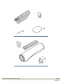
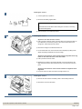
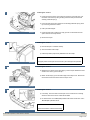
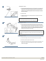
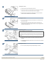
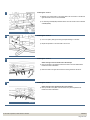
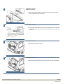
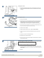
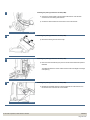
Installation instructions, accessories - Parking assistance module (PAM),
rear
XC90
Section Group Weight(Kg/Pounds) Year
3
36
Month
2004 02
XC90 2003, XC90 2004, XC90 2005, XC90 2006
R8600882
© VolvoCar Corporation, 2004 Printed in Sweden
30660633
Page 1 of 20
Installation instructions, accessories - Parking assistance module (PAM),
rear
Required tools
A0000161
A0000162
A0000163
A0000172
R0801579
A0801178
R8802817
R3602786
© VolvoCar Corporation, 2004 Printed in Sweden
30660633
Page 2 of 20
Installation instructions, accessories - Parking assistance module (PAM),
rear
R3603458
R3904312
© VolvoCar Corporation, 2004 Printed in Sweden
30660633
Page 3 of 20
Installation instructions, accessories - Parking assistance module (PAM),
rear
Any comments on this publication? Please contact your nearest dealer. Thank you!
Publication no: 30660633, Issue: 2004-02
Comments:..........................................................................................................
............................................................................................................................
............................................................................................................................
............................................................................................................................
............................................................................................................................
.............................................................................................................................
From:...................................................................................................................
Address:.............................................................................................................
Telephone no:................................................................................................... .
Telefax:...............................................................................................................
© VolvoCar Corporation, 2004 Printed in Sweden
30660633
Page 4 of 20
Installation instructions, accessories - Parking assistance module (PAM),
rear
INTRODUCTION
●
●
NOTE! Read through the entire text before carrying out
any work.
The front page gives the date of this edition and the edition it
replaces
Cars equipped with SRS/SIPS (Airbag)
Warning!
Extra care must be taken when working on cars equipped with SRS/SIPS
air bags. This is important to prevent:
1. Personal injury
The second page shows the tools needed for the installation and
the contents of the installation kit
2. Damage to or malfunction of the SRS/SIPS system.
●
The illustrations display the procedure in order of operation. The
order of operation is repeated in the text section
Work on the SRS/SIPS systems or related components must always be
carried out by an authorised Volvo workshop.
●
Cut out the text page in order to follow the illustrations and text at
the same time.
Is the car equipped with SRS (supplemental restraint system)?
●
Cars equipped with a driver's airbag have the letters "SRS" imprinted on
the centre panel of the steering wheel. Cars equipped with driver's and
passenger airbags are marked with "SRS" on both the steering wheel
centre panel and also on the dashboard close to the airbag.
If the car is equipped with SIPS (side impact protection system ) a "SIPS"
decal is marked on both the front seats.
Cars equipped with inflatable curtains have the marking "SRS" on one of
the panels along the posts on the inside of the car.
Cars equipped with SRS (supplemental restraint system) also have an
"SRS" decal on the front windscreen.
Warning!
The air bag inflation areas must not be obstructed. Never place any
objects, such as upholstery or accessories, within these areas. The
panels must be able to open in the correct manner at the right time,
otherwise there is an increased risk of personal injury in the event of a
collision.
Do not damage the SRS wiring!
Do not trap, chafe, pierce or damage the SRS wiring. SRS wiring has
orange casing and/or is plaited.
Steering and front suspension
The contact reel in the SRS system can easily be damaged when
working on the steering wheel, steering shaft or steering gear. Refer to
the SRS (supplemental restraint system) Service Manual or service
instructions in VIDA for information on carrying out such work. This is to
prevent damage.
SRS warning lamp
© VolvoCar Corporation, 2004 Printed in Sweden
30660633
Page 5 of 20
Installation instructions, accessories - Parking assistance module (PAM),
rear
If the SRS warning lamp lights after repairs have been carried out, take
the car to an authorised Volvo workshop.
C30/S40(04-)/V50/S60/C70(06-)/V70/S80/XC90 Supplemental
Restraint System Module (SRS)
The supplemental restraint system module (SRS) is located on the tunnel
under the centre console, in front of the parking brake.
Warning!
The ignition must be in position "0" and the key removed from the ignition
switch if any connector in the SRS system is to be unplugged. Then wait
at least three minutes and disconnect the battery negative lead before
unplugging any of the connectors. When work is completed, the ignition
key must be turned to position "II" before reconnecting the battery
negative lead.
Parking assistance module (PAM), rear
Note!
This accessory is connected to the electrical system of the car. It
requires software unique to the car.
© VolvoCar Corporation, 2004 Printed in Sweden
30660633
Page 6 of 20
Installation instructions, accessories - Parking assistance module (PAM),
rear
Installing the sensors
1
●
Turn the ignition key to position 0
●
Disconnect the battery negative lead.
Note!
Wait at least five minutes before disconnecting the connectors or removing
other electrical equipment.
A8800136
●
Clean the bumper. Use a mild soap solution.
Installing the sensors
2
●
Applies to cars with two rows of seats
Fold up the rear centre floor hatch. If the floor hatch has a carrier bag holder on
the underneath, it is secured by a strap on each of the shorter sides of the
storage box. These straps must be undone
●
Remove the storage box underneath and lift it out
●
On two-wheel drive cars, remove the floor hatch completely by folding it back
slightly and pulling it backwards out of its mountings.
R8503999
●
●
●
Applies to cars with three rows of seats and the integrated carrier bag
holder on the underside of the centre floor hatch
Fold up the rear centre floor hatch
Release the two straps on the panel underneath. Lift up the panel at the rear
edge. Fold back the floor hatch towards the panel. Lift out the floor hatch and
panel.
Applies to cars with three rows of seats without an integrated carrier
bag holder
Lift up the centre, rear floor hatch at the rear edge and lift it out.
Installing the sensors
3
●
Remove the three screws in the battery holder. Lift the battery holder out
●
Remove the cover from the battery.
R3100130
© VolvoCar Corporation, 2004 Printed in Sweden
30660633
Page 7 of 20
Installation instructions, accessories - Parking assistance module (PAM),
rear
Installing the sensors
4
●
Remove the four pre-punched sections (1) from the insulation panel in the rear
cross member
●
Remove the four nuts holding the bumper.
R3100131
Installing the sensors
5
●
Remove the panel under the rear lamps on the right and left-hand sides by
carefully prying off. Use a weatherstrip tool.
R8600873
Installing the sensors
6
●
Disconnect the connectors for the sidemarker lamps on the left and right-hand
sides. The connectors must be left in place in their brackets.
R8600896
Installing the sensors
7
●
Drill out the rivets in the rear edge of the wheel arch on the right and left-hand
sides. Use a 6 mm (1/4” ) diameter drill bit
●
Remove the remains of the rivets.
R8600883
© VolvoCar Corporation, 2004 Printed in Sweden
30660633
Page 8 of 20
Installation instructions, accessories - Parking assistance module (PAM),
rear
Installing the sensors
8
R8600897
●
Pull the ends of the bumper cover away from the body. Pull off the clips (1) at
the bottom and continue up along the wing extensions and pull off the three
vertically positioned clips (2)
●
Pull out the ends some more until the four horizontally positioned clips (3) at the
top of the wing extensions release
●
Fold up the lower tailgate
●
Pull the bumper back so that the two clips (4) which are accessible from the
space under the rear lamps release
●
Remove the bumper.
Installing the sensors
9
●
Place the bumper on a suitable underlay
●
Clean the outside of the bumper
●
Install the protective paper evenly distributed over the bumper.
Note!
R8600885
The paper protects the bumper and must be left in place throughout the operation.
Installing the sensors
10
●
Release the ten catches in the upper edge (1) of the bumper. Release the seven
catches in the centre (2) of the bumper
●
Detach the two stays (3) from the lower edge of the bumper cover. Remove the
rear section and the foam rubber from the bumper cover.
R8601016
Installing the sensors
11
●
If necessary, clean the inside of the bumper cover to locate the four markings
where the holes for the sensor holders will be drilled
●
Pre-drill the holes. Use a 3 mm (1/8”) diameter drill bit. Drill out the holes. Use a
12.5 mm (1/2”) diameter drill bit.
Note!
R8600887
© VolvoCar Corporation, 2004 Printed in Sweden
Ensure that the drill is horizontal when drilling.
30660633
Page 9 of 20
Installation instructions, accessories - Parking assistance module (PAM),
rear
Installing the sensors
12
●
Take the 27.5 mm (1 1/16”) diameter hole cutter (P/N 8671170). Install the hole
cutter in the holes; with the screw and the counterhold on the inside and the
cutting section on the outside as illustrated. Ensure that both parts of the hole
cutter are correctly positioned against the surface of the bumper cover before
starting to make holes
●
Expand the holes
●
The mark on the tool must be pointed upwards and correspond to the centre
marking on the cover.
R8600893
Note!
Clean the threads and surfaces of the tool after cutting each hole.
Installing the sensors
13
●
File out the two semi-circles marked around each hole. Use a small round file.
These ensure that each sensor is correctly positioned and does not rotate. The
two sensor holders which will be in the centre (1) are the same. The two sensor
holders which will be positioned to the sides (2) are different from each other
and from the sensors in the centre. The catches on the holders also have text
indicating the correct location in the bumper.
Note!
R8600888
The marking may be difficult to see. Carefully check that each sensor holder is correctly
positioned.
Installing the sensors
14
●
Ensure that the edge of the holes are smooth. File the holes if necessary
●
Remove the protective paper around the holes
●
Take the sensor holders from the kit. Press them into the correct positions in the
bumper cover. Press the sensor holders firmly into place. Check that all the
catches have engaged.
R8600889
© VolvoCar Corporation, 2004 Printed in Sweden
30660633
Page 10 of 20
Installation instructions, accessories - Parking assistance module (PAM),
rear
Installing the sensors
15
●
Take the sensors and the cable harness from the kit
●
Connect the connectors on the cable harness to the connectors on the sensors.
There must be a click which confirms that the catch has engaged
●
Press the sensors into place with the cable harness in the relevant holder so
that the connector is pointing to the left as illustrated.
R8600890
Installing the sensors
16
●
Place the four cables from the sensors so that they are in the vertical cut-outs
(2) in the foam rubber
●
Press the rear section with the foam rubber into place in the bumper cover.
Check that all the catches have engaged and that the stay has engaged around
the bottom of the bumper cover.
R8600891
Installing the sensors
Points 17-22 apply to cars with tow hitches
17
Note!
On cars with tow hitches, the cable harness for the sensors must be moved: This is to
prevent damage from rubbing against the rear edge of the mounting at the sides of the
tow hitch.
R8601043
●
Measure up to drill the cable lead-in in the upper of the rear section plates as
illustrated
●
Pre-drill using a 3 mm (1/8”) diameter drill bit. Then drill out the hole to a diameter
of 7 mm (9/32”).
Installing the sensors
18
●
Cut a 2 mm (5/64”) wide groove through the plate leading in to the hole.
R8601044
© VolvoCar Corporation, 2004 Printed in Sweden
30660633
Page 11 of 20
Installation instructions, accessories - Parking assistance module (PAM),
rear
Installing the sensors
19
●
Measure up to drill the lead-in in the upper plate in the rear section on the left and
right-hand sides of the cut-out as illustrated
●
Pre-drill using a 3 mm (1/8”) diameter drill bit. Then drill out the hole to a diameter
of 8 mm (5/16”).
R8601046
Installing the sensors
20
●
Cut a 2 mm (5/64”) wide groove through the plate leading in to the hole
●
Repeat the operation on the other side of the cut-out.
R8601047
Installing the sensors
21
●
Cable routing on the left-hand side of the bumper
Press up the tabs on the plates and insert the cable in the holes drilled earlier.
Position the cable as illustrated
●
Route the cable to the right-hand side of the existing cable duct as before.
R8601048
Installing the sensors
22
●
Cable routing on the right-hand side of the bumper
Press up the tab on the plate. Insert the cable in the previously drilled hole.
Position the cable as illustrated.
R8601049
© VolvoCar Corporation, 2004 Printed in Sweden
30660633
Page 12 of 20
Installation instructions, accessories - Parking assistance module (PAM),
rear
Installing the sensors
Applies to all models
23
●
Press the large cable harness for the sensors into place in the existing cable
duct (1) in the bottom of the rear section.
R8600983
Installing the sensors
24
●
Take the piece of foam tape from the kit. Install the foam tape over the cable leadin on the right-hand side of the rear section of the bumper so that the cable does
not fall out.
R3703117
Installing the sensors
25
●
Remove the left-hand floor hatch (1).
R8504000
Installing the sensors
26
●
Remove the folding side panel from the left-hand side in the cargo compartment.
R8504080
© VolvoCar Corporation, 2004 Printed in Sweden
30660633
Page 13 of 20
Installation instructions, accessories - Parking assistance module (PAM),
rear
Installing the sensors
27
●
Remove the expanded polystyrene seal on the left-hand side in the rear cross
member under the left-hand side floor hatch. Do not damage the seal, it will be
used again.
R8903013
Installing the sensors
28
●
Fold up the lower tailgate
●
Reinstall the bumper. Insert the cable from the sensors in the large rectangular
hole to the left in the rear cross member and then on to the hole where the
expanded polystyrene seal was located. Ensure that the wiring for the
sidemarker lamps is in the correct grooves in the spaces under the tail lamps
●
Press the four clips for the bumper into place above the sidemarker lamps on the
body. Then secure all the clips for the ends to the body
●
Fold down the lower tailgate
●
Tighten the bumper using the four nuts. Tighten to 16 Nm (12 lbf.ft.)
●
Take the new pieces of insulation and reinstall them above the holes for the
bumper
●
Connect the connectors to the sidemarker lamps
●
Reinstall the covers under the tail lamps
●
Rivet the bumper into place at the rear edges of the wheel arches on both sides.
Use the rivets from the kit.
R8600911
Installing the parking assistance module (PAM)
Points 29-33 apply to four wheel drive cars, and all cars from model year 2005-
29
Note!
The relay does not need to be installed on four-wheel drive cars.
●
Clean the flat surface on the panel behind the control module where the Velcro
strips will be pressed into place. Use a mixture of 30% windscreen washer fluid
and 70% water
●
Wipe dry.
R8504475
© VolvoCar Corporation, 2004 Printed in Sweden
30660633
Page 14 of 20
Installation instructions, accessories - Parking assistance module (PAM),
rear
Installing the parking assistance module (PAM)
30
●
Connect the control module to the pre-routed cable harness. Use the black
connector from the existing cable harness
●
Connect the cable harness from the sensors to the control module.
R3904972
Installing the parking assistance module (PAM)
31
●
Remove the backing from the Velcro strips.
R3904251
Installing the parking assistance module (PAM)
32
●
Press the control module firmly into place on the flat surface behind the panel as
illustrated.
The visible left side of the control module must be at the same height as the edge
of the plate (1).
R8504469
Installing the parking assistance module (PAM)
33
●
Reinstall the expanded polystyrene seal together with the cable harness from
the sensors in the hole in the rear cross member.
R3904120
© VolvoCar Corporation, 2004 Printed in Sweden
30660633
Page 15 of 20
Installation instructions, accessories - Parking assistance module (PAM),
rear
Installing the parking assistance module (PAM) and relay
Points 34-43 apply to two wheel drive cars up to and including model year 2004
34
R3903738
●
Pull off the rubber strip at the rear edge of the door opening to the left-hand rear
door opposite the left C-post panel
●
Carefully pry off the left-hand C-post panel sides at the top. Use a plastic
weatherstrip tool. Then pull until the three clips on the inside release. Do not
damage the headlining or the panel
●
Remove the panel by pulling upwards slightly and unhooking it from the side
panel.
Installing the parking assistance module (PAM) and relay
35
●
Remove the covers and the screws underneath for the rear headlining
●
Carefully pry off the panel at the rear edge. Use a plastic weatherstrip tool
●
Pull the rear edge of the panel downwards until the four clips on the top release
●
If the car has lighting in the panel, disconnect the connector
●
Pull the panel backwards to release it.
R8504201
Installing the parking assistance module (PAM) and relay
36
●
Carefully pull off the D-post panel. Start at the top edge then pull down until the
three clips on the inside release. Do not damage the panel
●
Disconnect the connector on the D-post panel (if the car has a loudspeaker in
the D-post, the connector is in the loudspeaker)
●
Remove the panel by pulling upwards slightly and unhooking it from the side
panel.
R8504123
© VolvoCar Corporation, 2004 Printed in Sweden
30660633
Page 16 of 20
Installation instructions, accessories - Parking assistance module (PAM),
rear
Installing the parking assistance module (PAM) and relay
37A
Illustration A shows the removal of the cover for the load securing eyelets
R8504313
●
Fold out the load securing eyelet
●
Insert a scriber with an angled tip into the hole in the top of the cover
●
Turn the scriber so that the angled tip engages in the reverse of the cover (1).
Pull the cover off.
Illustration B applies to cars with two rows of seats
Illustration C applies to cars with three rows of seats
37B
●
Remove the two screws (2) from under the cover
●
Remove the covers (3) over the front mountings for the left-hand side panel. Pry
the covers off. Use a plastic weatherstrip tool or a small screwdriver
●
Remove the screws (4)
●
Remove the clip (5) at the bottom of the storage compartment in the panel
(Applies to cars with three rows of seats)
●
Pull out the panel slightly at the top edge so that the clips on the inside release.
Remove the panel by pulling it straight upwards.
R8504315
37C
R8504316
Installing the parking assistance module (PAM) and relay
38
●
Clean the flat surface where the Velcro strips will be applied. Use a mixture of
30% windscreen washer fluid and 70% water
●
Wipe dry.
R3904252
© VolvoCar Corporation, 2004 Printed in Sweden
30660633
Page 17 of 20
Installation instructions, accessories - Parking assistance module (PAM),
rear
Installing the parking assistance module (PAM) and relay
39
●
Connect the control module to the pre-routed cable harness. Use the black
connector from the existing cable harness
●
Connect the cable harness from the sensors to the control module.
R3904973
Installing the parking assistance module (PAM) and relay
40
●
Remove the backing from the Velcro strips.
R3904251
Installing the parking assistance module (PAM) and relay
41
●
Press the control module firmly into place on the flat surface, with the wiring
positioned behind the existing thick cable harness as illustrated.
The left side of the control module must be at the same height as the edge of the
plate (1).
R3904255
Installing the parking assistance module (PAM) and relay
42
●
Reinstall the expanded polystyrene seal together with the cable harness from
the sensors in the hole in the rear cross member.
R3904120
© VolvoCar Corporation, 2004 Printed in Sweden
30660633
Page 18 of 20
Installation instructions, accessories - Parking assistance module (PAM),
rear
Installing the parking assistance module (PAM) and relay
43
●
Take the relay from the kit. Install the relay in position MA1 in the lower front
corner of the fuse holder.
R3703033
Installing the switch
44
●
Applies to cars from model year 2005-: Proceed directly to point 45.
●
Only applies to cars up to and including model year -2004: Install a 20A
fuse from the kit in position 15 in the rear fuse holder.
R3702947
Installing the switch
45A
Illustration A
R8504177
45B
●
Remove the blind cover plug from the 12V socket
●
Take a scriber with an angled tip
●
Insert the angled end of the scriber in the joint on the underneath of the surround
for the switch unit.
Illustration B
●
Carefully pull out the surround using the scriber along the underneath of the
surround. The surround is secured by three mounting lugs at the top and lower
edges. Do not damage the surround
●
Place the surround to one side.
The surround with four button spaces can be replaced by a surround with seven button
spaces if necessary. This surround is purchased separately.
R8504178
© VolvoCar Corporation, 2004 Printed in Sweden
30660633
Page 19 of 20
Installation instructions, accessories - Parking assistance module (PAM),
rear
Installing the switch
46
The switch can be installed in any location.
●
Remove the switch blank. Install the new switch (1)
●
Reinstall the surround and the blind cover plug for the 12V socket.
D8502226
Installing the switch
Applies only to two wheel drive cars up to and including model year -2004
47
●
Reinstall:
the left-hand side panel using the screws and cover. Tighten the screws in the
load securing eyelets. Tighten to 24 Nm (18 lbf.ft.)
●
the covers for the load securing eyelets
●
The D-post panel with the connector
●
the connector for the rear roof lighting (if applicable)
●
the rear headlining
●
the C-post panel.
Finishing work
48
A8800137
© VolvoCar Corporation, 2004 Printed in Sweden
●
Turn the ignition key to position II
●
Reconnect the battery negative lead
●
Reinstall the left-hand folding panel and the left floor hatch
●
Reinstall the floor hatches and the storage compartment
●
Program the software according to the service information in VIDA.
30660633
Page 20 of 20