1
HP 8200 zl Switches
Installation and Getting Started Guide
Power over Ethernet
HP 8200 zl Switches
Installation and Getting Started Guide
© Copyright 2011, 2013 Hewlett-Packard Development Company,
L.P.
Redundant Wireless Services zl Module
J9052A
ONE Services zl Module
J9154A
Publication Number
HP 24-port Gig-T PoE+ v2 zl Module
J9534A
5998-2999
June 2013
HP 20-port Gig-T PoE+ / 4-port SFP v2 zl Module
J9535A
Applicable Products
HP 24-port SFP v2 zl Module
J9537A
HP 8-port 10-GbE SFP+ v2 zl Module
J9538A
HP 8-port 10GBase-T v2 zl Module
J9546A
HP 24-port 10/100 PoE+ v2 zl Module
J9547A
HP 20-port Gig-T / 2-port 10-GbE SFP+ v2 zl Module
J9548A
HP 20-port Gig-T / 4-port SFP v2 zl Module
J9549A
HP 24-port Gig-T v2 zl Module
J9550A
HP 12-port Gig-T / 12-port SFP v2 zl Module
J9637A
HP 20-port Gig-T PoE+ / 2-port 10-GbE SFP+ v2 zl Module J9536A
HP Switch 8212 zl
(Base System)
J8715A/B
HP Switch 8212 zl
(Replacement Chassis with Fan Tray Only)
J9091A/B
HP Switch 8206 zl
(Base System)
J9475A
HP Switch 8212 zl Fan Tray
(Replacement Fan Tray Only)
J9094A
HP Switch 8206 zl Fan Tray
(Replacement Fan Tray Only)
J9476A
HP 8206-44G-PoE+/2XG-SFP+ v2 zl Switch with Premium
Software
J9638A
HP 8212-92G-PoE+/2XG-SFP+ v2 zl Switch with Premium
Software
J9639A
HP 8206 v2 zl Switch with Premium Software
J9640A
HP 8212 v2 zl Switch with Premium Software
J9641A
Switch zl Power Supply Shelf
J8714A
Switch zl Power Supply Shelf Rack Mounting Kit
5070-3028
Two-Post Rack Mounting Kit for Switch 8212 zl
5070-2983
8200 zl/5400 zl 10K Rack Rail Kit Assembly
5070-0145
HP ProCurve 1500W PoE+ zl Power Supply
J9306A
HP ProCurve 875W PoE zl Power Supply
J8712A
HP ProCurve 1500W PoE zl Power Supply
J8713A
HP ProCurve 8200 zl Management Module
J9092A
HP ProCurve 8200 zl System Support Module
J9095A
HP ProCurve 8200 zl Fabric Module
J9093A
Compact Flash Kit for 8200 zl Management Module
5070-3051
24-port Gig-T zl Module
J8702A
20-port Gig-T/SFP zl Module
J8705A
24-port mini-GBIC zl Module
J8706A
4-port 10Gig-X2 zl Module
J8707A
4-port 10Gig-CX4 zl Module
J8708A
24-Port 10/100/1000 PoE+ zl Module
J9307A
20-Port 10/100/1000 PoE+/4-Port MiniGBIC zl Module
J9308A
4-Port 10GbE SFP+ zl Module
J9309A
24-Port 10/100 PoE+ zl Module
J9478A
Wireless Edge Services zl Module
J9051A
Hewlett-Packard Company
8000 Foothills Boulevard, m/s 5551
Roseville, California 95747-5551
http://www.hp.com/networking
Disclaimer
HEWLETT-PACKARD COMPANY MAKES NO WARRANTY
OF ANY KIND WITH REGARD TO THIS MATERIAL,
INCLUDING, BUT NOT LIMITED TO, THE IMPLIED
WARRANTIES OF MERCHANTABILITY AND FITNESS
FOR A PARTICULAR PURPOSE. Hewlett-Packard shall not
be liable for errors contained herein or for incidental or
consequential damages in connection with the furnishing,
performance, or use of this material.
The information contained herein is subject to change
without notice. The only warranties for HP products and
services are set forth in the express warranty statements
accompanying such products and services. Nothing herein
should be construed as constituting an additional warranty.
HP shall not be liable for technical or editorial errors or
omissions contained herein.
Hewlett-Packard assumes no responsibility for the use or
reliability of its software on equipment that is not furnished
by Hewlett-Packard.
Warranty
For HP warranty information, visit
www.hp.com/networking/support
A copy of the specific warranty terms applicable to your
Hewlett-Packard products and replacement parts can be
obtained from your HP Sales and Service Office or
authorized dealer.
Safety
Before installing and operating these products, please read
the “Installation Precautions” in chapter 2, and “Safety and
Regulatory Statements” in Appendix C.
iii
Contents
1 Introducing the HP 8200 zl Switches
Overview of the 8200 zl Switches . . . . . . . . . . . . . . . . . . . . . . . . . . . . . . . . . . 1-2
8206 zl Switches . . . . . . . . . . . . . . . . . . . . . . . . . . . . . . . . . . . . . . . . . . . . . 1-2
8212 zl Switch . . . . . . . . . . . . . . . . . . . . . . . . . . . . . . . . . . . . . . . . . . . . . . 1-3
Network Connectivity, Speeds and Technologies . . . . . . . . . . . . . . . . . . . . 1-4
Front of the 8200 zl Switches . . . . . . . . . . . . . . . . . . . . . . . . . . . . . . . . . . . . . 1-5
Front of 8212 zl Switch, Base System . . . . . . . . . . . . . . . . . . . . . . . . . . . 1-5
Front of 8206 zl Switch, Base System . . . . . . . . . . . . . . . . . . . . . . . . . . . 1-6
Switch and Module LEDs . . . . . . . . . . . . . . . . . . . . . . . . . . . . . . . . . . . . . 1-7
LED Mode Select Button and Indicator LEDs . . . . . . . . . . . . . . . 1-12
Console Port . . . . . . . . . . . . . . . . . . . . . . . . . . . . . . . . . . . . . . . . . . . 1-13
Reset Buttons . . . . . . . . . . . . . . . . . . . . . . . . . . . . . . . . . . . . . . . . . . 1-13
Module Reset . . . . . . . . . . . . . . . . . . . . . . . . . . . . . . . . . . . . . . . . . . 1-13
System Reset . . . . . . . . . . . . . . . . . . . . . . . . . . . . . . . . . . . . . . . . . . . 1-13
Clear Button . . . . . . . . . . . . . . . . . . . . . . . . . . . . . . . . . . . . . . . . . . . 1-14
Back of the 8200 zl Switches . . . . . . . . . . . . . . . . . . . . . . . . . . . . . . . . . . . . .
Back of the 8212 zl Switch . . . . . . . . . . . . . . . . . . . . . . . . . . . . . . . . . . .
Back of the 8206 zl Switch . . . . . . . . . . . . . . . . . . . . . . . . . . . . . . . . . . .
Power Supply . . . . . . . . . . . . . . . . . . . . . . . . . . . . . . . . . . . . . . . . . . . . . .
1-15
1-15
1-16
1-16
Switch Accessories . . . . . . . . . . . . . . . . . . . . . . . . . . . . . . . . . . . . . . . . . . . . . 1-17
Switch Features . . . . . . . . . . . . . . . . . . . . . . . . . . . . . . . . . . . . . . . . . . . . . . . 1-19
2 Installing the HP 8200 zl Switches
Included Parts . . . . . . . . . . . . . . . . . . . . . . . . . . . . . . . . . . . . . . . . . . . . . . . . . . 2-1
Power Cords . . . . . . . . . . . . . . . . . . . . . . . . . . . . . . . . . . . . . . . . . . . . . . . . . . . 2-2
Installation Procedures . . . . . . . . . . . . . . . . . . . . . . . . . . . . . . . . . . . . . . . . . . 2-3
Summary . . . . . . . . . . . . . . . . . . . . . . . . . . . . . . . . . . . . . . . . . . . . . . . . . . . 2-3
Installation Precautions . . . . . . . . . . . . . . . . . . . . . . . . . . . . . . . . . . . . . . 2-5
iii
1. Prepare the Installation Site . . . . . . . . . . . . . . . . . . . . . . . . . . . . . . . . 2-7
Cabling Infrastructure . . . . . . . . . . . . . . . . . . . . . . . . . . . . . . . . . . . . 2-7
Installation Location . . . . . . . . . . . . . . . . . . . . . . . . . . . . . . . . . . . . . 2-7
2. Mount the Switch Chassis . . . . . . . . . . . . . . . . . . . . . . . . . . . . . . . . . . 2-7
Rack or Cabinet Mounting . . . . . . . . . . . . . . . . . . . . . . . . . . . . . . . . 2-7
Horizontal Surface Mounting . . . . . . . . . . . . . . . . . . . . . . . . . . . . . 2-10
3. Install the Switch Modules . . . . . . . . . . . . . . . . . . . . . . . . . . . . . . . . . 2-11
Installing a Management Module Battery . . . . . . . . . . . . . . . . . . . 2-13
4. Install the Power Supplies . . . . . . . . . . . . . . . . . . . . . . . . . . . . . . . . . 2-14
5. Verify the Switch Passes Self Test . . . . . . . . . . . . . . . . . . . . . . . . . . 2-17
LED Behavior: . . . . . . . . . . . . . . . . . . . . . . . . . . . . . . . . . . . . . . . . . 2-19
6. Install the Grounding Wire . . . . . . . . . . . . . . . . . . . . . . . . . . . . . . . . . 2-20
7. Connect the Switch to a Power Source . . . . . . . . . . . . . . . . . . . . . . 2-21
8. (Optional) Connect a Power Supply Shelf
to the switch . . . . . . . . . . . . . . . . . . . . . . . . . . . . . . . . . . . . . . . . . . . . . 2-21
EPS Operation . . . . . . . . . . . . . . . . . . . . . . . . . . . . . . . . . . . . . . . . . 2-22
Operating Characteristics of the EPS (J8714A) . . . . . . . . . . . . . . 2-22
Power Supply Shelf LEDs . . . . . . . . . . . . . . . . . . . . . . . . . . . . . . . . 2-22
Connecting the Power Supply Shelf . . . . . . . . . . . . . . . . . . . . . . . 2-24
9. Connect the Network Devices . . . . . . . . . . . . . . . . . . . . . . . . . . . . . . 2-25
10. (Optional) Connect a Console to the Switch . . . . . . . . . . . . . . . . . 2-27
Terminal Configuration . . . . . . . . . . . . . . . . . . . . . . . . . . . . . . . . . . 2-27
Direct Console Access . . . . . . . . . . . . . . . . . . . . . . . . . . . . . . . . . . . 2-28
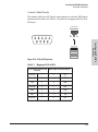
Console Cable Pinouts . . . . . . . . . . . . . . . . . . . . . . . . . . . . . . . . . . 2-29
Telnet Console Access . . . . . . . . . . . . . . . . . . . . . . . . . . . . . . . . . . 2-30
Hot Swapping Switch Modules . . . . . . . . . . . . . . . . . . . . . . . . . . . . . . . . . . . 2-30
Adding or Replacing Modules . . . . . . . . . . . . . . . . . . . . . . . . . . . . . . . . 2-30
Changing the Module Type . . . . . . . . . . . . . . . . . . . . . . . . . . . . . . . . . . 2-31
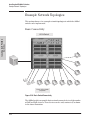
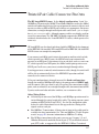
Example Network Topologies . . . . . . . . . . . . . . . . . . . . . . . . . . . . . . . . . . .
Basic Connectivity . . . . . . . . . . . . . . . . . . . . . . . . . . . . . . . . . . . . . . . . .
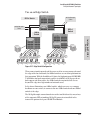
Use as an Edge Switch . . . . . . . . . . . . . . . . . . . . . . . . . . . . . . . . . . . . . .
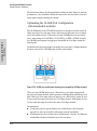
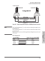
Optimizing the 10-GbE Port Configuration
with standard zl modules . . . . . . . . . . . . . . . . . . . . . . . . . . . . . . . . . . .
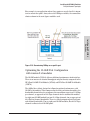
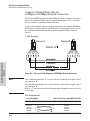
Optimizing the 10-GbE Port Configuration
with version 2 zl modules . . . . . . . . . . . . . . . . . . . . . . . . . . . . . . . . . . .
iv
2-32
2-32
2-33
2-34
2-35
3 Getting Started With Switch Configuration
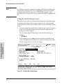
Recommended Minimal Configuration . . . . . . . . . . . . . . . . . . . . . . . . . .
Using the Switch Setup Screen . . . . . . . . . . . . . . . . . . . . . . . . . . . . . . . .
Where to Go From Here . . . . . . . . . . . . . . . . . . . . . . . . . . . . . . . . . . . . . .
To Recover from a Lost Manager Password: . . . . . . . . . . . . . . . . .
3-1
3-2
3-4
3-4
Using the IP Address for Remote Switch Management . . . . . . . . . . . . . . . . 3-5
Starting a Telnet Session . . . . . . . . . . . . . . . . . . . . . . . . . . . . . . . . . . . . . 3-5
Starting a Web Browser Session . . . . . . . . . . . . . . . . . . . . . . . . . . . . . . . 3-5
Configuring the ProCurve Wireless Edge Services zl Module (J9051A) . . 3-7
Configuring an IP Address for the Module . . . . . . . . . . . . . . . . . . . . . . . 3-7
Configuring VLANs on the zl Switch . . . . . . . . . . . . . . . . . . . . . . . . . . . . 3-9
Determining a Module Configuration Backup Process . . . . . . . . . . . . 3-9
Configuring Wireless LAN Services . . . . . . . . . . . . . . . . . . . . . . . . . . . 3-10
4 Replacing Components
Replacing Power Supplies . . . . . . . . . . . . . . . . . . . . . . . . . . . . . . . . . . . . . . . . 4-2
Replacing Fan Trays . . . . . . . . . . . . . . . . . . . . . . . . . . . . . . . . . . . . . . . . . . . . . 4-5
Replacing the Management Module . . . . . . . . . . . . . . . . . . . . . . . . . . . . . . . . 4-6
Replacing the Management Module Compact Flash Card . . . . . . . . . . . . . 4-8
Installing a Compact Flash Card . . . . . . . . . . . . . . . . . . . . . . . . . . . . . . . 4-8
Replacing the Services Module Compact Flash Card . . . . . . . . . . . . . . . . . 4-9
Installing a Compact Flash Card . . . . . . . . . . . . . . . . . . . . . . . . . . . . . . . 4-9
Replacing the Services Module Disk Drive . . . . . . . . . . . . . . . . . . . . . . . . . 4-10
Installing a Disk Drive . . . . . . . . . . . . . . . . . . . . . . . . . . . . . . . . . . . . . . 4-10
5 Troubleshooting
Basic Troubleshooting Tips . . . . . . . . . . . . . . . . . . . . . . . . . . . . . . . . . . . . . . 5-1
Diagnosing with the LEDs . . . . . . . . . . . . . . . . . . . . . . . . . . . . . . . . . . . . . . . . 5-4
Proactive networking . . . . . . . . . . . . . . . . . . . . . . . . . . . . . . . . . . . . . . . . . . . . 5-9
Hardware Diagnostic Tests . . . . . . . . . . . . . . . . . . . . . . . . . . . . . . . . . . . . . . 5-10
Reasons for Resetting the Switch . . . . . . . . . . . . . . . . . . . . . . . . . . . . . 5-10
v
Methods of Resetting the Switch . . . . . . . . . . . . . . . . . . . . . . . . . . . . . .
Testing the Switch by Resetting It . . . . . . . . . . . . . . . . . . . . . . . . . . . .
Checking the Switch LEDs . . . . . . . . . . . . . . . . . . . . . . . . . . . . . . .
Checking Console Messages . . . . . . . . . . . . . . . . . . . . . . . . . . . . . .
Testing Twisted-Pair Cabling . . . . . . . . . . . . . . . . . . . . . . . . . . . . . . . . .
Testing Switch-to-Device Network Communications . . . . . . . . . . . .
Testing End-to-End Network Communications . . . . . . . . . . . . . . . . .
5-10
5-11
5-11
5-11
5-12
5-12
5-12
Restoring the Factory Default Configuration . . . . . . . . . . . . . . . . . . . . . . . 5-13
Downloading New Code . . . . . . . . . . . . . . . . . . . . . . . . . . . . . . . . . . . . . . . . 5-14
HP Customer Support Services . . . . . . . . . . . . . . . . . . . . . . . . . . . . . . . . . . 5-14
Before Calling Support . . . . . . . . . . . . . . . . . . . . . . . . . . . . . . . . . . . . . . 5-14
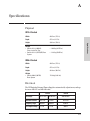
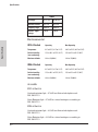
A Specifications
Physical . . . . . . . . . . . . . . . . . . . . . . . . . . . . . . . . . . . . . . . . . . . . . . . . . . .
Electrical . . . . . . . . . . . . . . . . . . . . . . . . . . . . . . . . . . . . . . . . . . . . . . . . .
Environmental . . . . . . . . . . . . . . . . . . . . . . . . . . . . . . . . . . . . . . . . . . . . .
Acoustic . . . . . . . . . . . . . . . . . . . . . . . . . . . . . . . . . . . . . . . . . . . . . . . . . .
8212 zl Switch . . . . . . . . . . . . . . . . . . . . . . . . . . . . . . . . . . . . . . . . . .
8206 zl Switch . . . . . . . . . . . . . . . . . . . . . . . . . . . . . . . . . . . . . . . . . .
Safety . . . . . . . . . . . . . . . . . . . . . . . . . . . . . . . . . . . . . . . . . . . . . . . . . . . .
EMC compliance (Class A) . . . . . . . . . . . . . . . . . . . . . . . . . . . . . . . . . .
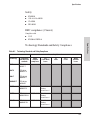
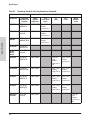
Technology Standards and Safety Compliance . . . . . . . . . . . . . . . . . .
A-1
A-1
A-2
A-2
A-2
A-2
A-3
A-3
A-3
B Switch Ports and Network Cables
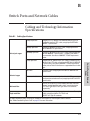
Cabling and Technology Information Specifications . . . . . . . . . . . . . . . . B-1
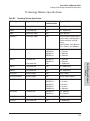
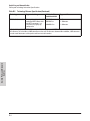
Technology Distance Specifications . . . . . . . . . . . . . . . . . . . . . . . . . . . B-3
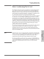
Mode Conditioning Patch Cord . . . . . . . . . . . . . . . . . . . . . . . . . . . . . . . . . . B-5
Installing the Patch Cord . . . . . . . . . . . . . . . . . . . . . . . . . . . . . . . . . . . . B-6
Twisted-Pair Cable/Connector Pin-Outs . . . . . . . . . . . . . . . . . . . . . . . . . . .
Straight-Through Twisted-Pair Cable for
10 Mbps or 100 Mbps Network Connections . . . . . . . . . . . . . . . . . . . .
Cable Diagram . . . . . . . . . . . . . . . . . . . . . . . . . . . . . . . . . . . . . . . . .
Pin Assignments . . . . . . . . . . . . . . . . . . . . . . . . . . . . . . . . . . . . . . . .
vi
B-7
B-8
B-9
B-9
Crossover Twisted-Pair Cable for
10 Mbps or 100 Mbps Network Connection . . . . . . . . . . . . . . . . . . . .
Cable Diagram . . . . . . . . . . . . . . . . . . . . . . . . . . . . . . . . . . . . . . . .
Pin Assignments . . . . . . . . . . . . . . . . . . . . . . . . . . . . . . . . . . . . . . .
Straight-Through Twisted-Pair Cable for
1000 Mbps Network Connections . . . . . . . . . . . . . . . . . . . . . . . . . . . .
Cable Diagram . . . . . . . . . . . . . . . . . . . . . . . . . . . . . . . . . . . . . . . .
Pin Assignments . . . . . . . . . . . . . . . . . . . . . . . . . . . . . . . . . . . . . . .
B-10
B-10
B-10
B-11
B-11
B-11
C Safety and Regulatory Statements
Safety Information . . . . . . . . . . . . . . . . . . . . . . . . . . . . . . . . . . . . . . . . . . . . . C-1
Informations concernant la sécurité . . . . . . . . . . . . . . . . . . . . . . . . . . . . . . C-2
Hinweise zur Sicherheit . . . . . . . . . . . . . . . . . . . . . . . . . . . . . . . . . . . . . . . . . C-3
Considerazioni sulla sicurezza . . . . . . . . . . . . . . . . . . . . . . . . . . . . . . . . . . . C-4
Consideraciones sobre seguridad . . . . . . . . . . . . . . . . . . . . . . . . . . . . . . . . C-5
Informações de Segurança . . . . . . . . . . . . . . . . . . . . . . . . . . . . . . . . . . . . . . C-6
Safety Information (Japan) . . . . . . . . . . . . . . . . . . . . . . . . . . . . . . . . . . . . . . C-7
Safety Information (China) . . . . . . . . . . . . . . . . . . . . . . . . . . . . . . . . . . . . . . C-8
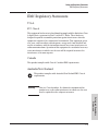
EMC Regulatory Statements . . . . . . . . . . . . . . . . . . . . . . . . . . . . . . . . . . . . . C-9
U.S.A. . . . . . . . . . . . . . . . . . . . . . . . . . . . . . . . . . . . . . . . . . . . . . . . . . . . . C-9
Canada . . . . . . . . . . . . . . . . . . . . . . . . . . . . . . . . . . . . . . . . . . . . . . . . . . . C-9
Australia/New Zealand . . . . . . . . . . . . . . . . . . . . . . . . . . . . . . . . . . . . . . C-9
Japan . . . . . . . . . . . . . . . . . . . . . . . . . . . . . . . . . . . . . . . . . . . . . . . . . . . . C-10
Korea . . . . . . . . . . . . . . . . . . . . . . . . . . . . . . . . . . . . . . . . . . . . . . . . . . . . C-10
Taiwan . . . . . . . . . . . . . . . . . . . . . . . . . . . . . . . . . . . . . . . . . . . . . . . . . . C-10
Regulatory Model Identification Number . . . . . . . . . . . . . . . . . . . . . C-10
European Community . . . . . . . . . . . . . . . . . . . . . . . . . . . . . . . . . . . . . . C-11
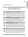
D Recycle Statements
Waste Electrical and Electronic Equipment (WEEE) Statements . . . . . . D-1
Index
vii
1
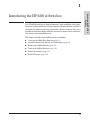
The HP 8200 zl switches are high-performance, high availability switch platforms that enable unified core-to-edge adaptive network solutions and deliver
to market the industry’s first core switch with a lifetime warranty. They have
platform and software high-availability features to ensure system continuity
and enhanced network productivity.
This chapter describes your 8200 zl switches, including:
■
Overview of 8200 zl Base Switches, page 1-2
■
Network Connectivity, Speeds and Technologies, page 1-4
■
Front of the 8200 zl Switches, page 1-5
■
Back of the 8200 zl Switches, page 1-15
■
Switch Accessories, page 1-17
■
Switch Features, page 1-19
1-1
Introducing the HP 8200 zl
Switches
Introducing the HP 8200 zl Switches
Introducing the HP 8200 zl Switches
Overview of the 8200 zl Switches
Introducing the HP 8200 zl
Switches
Overview of the 8200 zl Switches
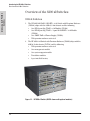
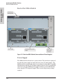
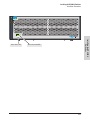
8206 zl Switches
1.
The HP 8206-44G-PoE+/2XG-SFP+ v2 zl Switch with Premium Software
(J9638A) ships with the 8206 zl, 6-slot chassis and the following:
• One HP 24-port Gig-T PoE+ v2 zl Module (J9534A)
• One HP 20-port Gig-T PoE+ / 2-port 10-GbE SFP+ v2 zl Module
(J9536A)
• One 1500W PoE+ zl Power Supply (J9306A)
• With premium software activated
2.
The HP 8206 v2 zl Switch with Premium Software (J9640A) ships with the
8206 zl, 6-slot chassis (J9475A) and the following:
• With premium software activated
• One management module
• One system support module
• Two fabric modules
• A pre-installed fan tray
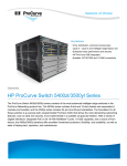
Figure 1-1. HP 8206 zl Switch (J9475A shown with optional modules)
1-2
Introducing the HP 8200 zl Switches
Overview of the 8200 zl Switches
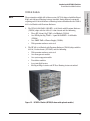
8212 zl Switch
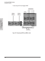
The previously available 8212 zl base system (J8715A) shipped with Intelligent
Edge and Advanced Routing features standard. Going forward, customers
requiring an 8212 zl with Advanced Routing features should order the J9641A
8212 v2 zl Switch with Premium Software.
1.
The HP 8212-92G-PoE+/2XG-SFP+ v2 zl Switch with Premium Software
(J9639A) ships with the 8212 zl, 12-slot chassis and the following:
• Three HP 24-port Gig-T PoE+ v2 zl Module (J9534A)
• One HP 20-port Gig-T PoE+ / 2-port 10-GbE SFP+ v2 zl Module
(J9536A)
• One 1500W PoE+ zl Power Supply (J9306A)
• With premium software activated
2.
The HP 8212 v2 zl Switch with Premium Software (J9641A) ships with the
8212 zl, 12-slot chassis (J8715A/B) and the following:
• With premium software activated
• One management module
• One system support module
• Two fabric modules
• A pre-installed fan tray
• Intelligent Edge features and IP Base Routing features standard
Figure 1-2. HP 8212 zl Switch (J8715A/B shown with optional modules)
1-3
Introducing the HP 8200 zl
Switches
Note
Introducing the HP 8200 zl
Switches
Introducing the HP 8200 zl Switches
Network Connectivity, Speeds and Technologies
Network Connectivity, Speeds and
Technologies
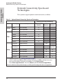
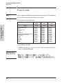
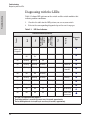
These products support optional network connectivity as follows:
Table 1-1.
Optional Network Connectivity, Speeds and Technologies
Transceiver Form-Factor and Connector1
Speed
Technology
Cabling
SFP ("mini-GBIC")
Connector
X2
Connector
SFP+
Connector
100-FX
Fiber (multimode)
LC
100-BX
Fiber (single mode)
LC
1000-T
Copper (twisted-pair)
1000-SX
Fiber (multimode)
LC
1000-LX
Fiber (multimode or single mode)
LC
1000-LH
Fiber (single mode)
LC
1000-BX
Fiber (single mode)
LC
10-Gig CX4
Copper (twinaxial)
10-Gig
Direct Attach
Copper (twinaxial)
10-Gig SR
Fiber (multimode)
SC
LC
10-Gig LRM
Fiber (multimode)
SC
LC
10-Gig LR
Fiber (single mode)
SC
LC
10-Gig ER
Fiber (single mode)
SC
LC
100 Mbps
1 Gbps
10 Gbps
1 For supported transceivers, visit
RJ-45
CX4
Not
Applicable
www.hp.com/networking/support.
– In the first textbox, type J4858 (for 100-Mb and Gigabit information), or J8436 (for 10-Gigabit information).
– Select any of the products that display in the dropdown list. Click Display selected.
– Select Product support information. Then click on Manuals and find the Transceiver Support Matrix.
For technical details of cabling and technologies see "Cabling and Technology Information" in the appendices.
1-4
Introducing the HP 8200 zl Switches
Front of the 8200 zl Switches
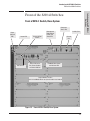
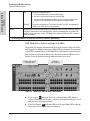
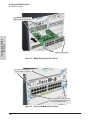
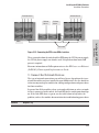
Front of 8212 zl Switch, Base System
Component
Status LEDs
Power
and Fault
LEDs
Locator LED
Self Test LED
Reset and Clear
buttons
Status LEDs for the
Fans, Power Supplies,
and Switch Modules
Management
Module Reset
button, and
StatusLEDs
Auxiliary Port
Console
Port
LED Mode Select button
and indicator LEDs
Switch Modules and slots
with Link and Mode LEDs for each port located on each module
Figure 1-3. Front of 8212 zl Switch, Base System
1-5
Introducing the HP 8200 zl
Switches
Front of the 8200 zl Switches
Introducing the HP 8200 zl
Switches
Introducing the HP 8200 zl Switches
Front of the 8200 zl Switches
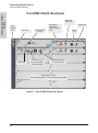
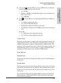
Front of 8206 zl Switch, Base System
Component
Status LEDs
Power
and Fault
LEDs
Locator LED
Self Test LED
Reset and Clear
buttons
Status LEDs for the
Fans, Power Supplies,
and Switch Modules
Management
Module Reset
button, and Status
LEDs
LED Mode Select button
and indicator LEDs
Switch Modules and slots
with Link and Mode LEDs for each port located on each module
Figure 1-4. Front of 8206 zl Switch, Base System
1-6
Auxiliary Port
Console
Port
Introducing the HP 8200 zl Switches
Front of the 8200 zl Switches
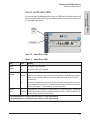
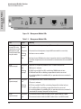
Switch and Module LEDs
Power
and Fault
LEDs
Locator LED
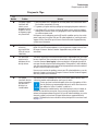
Figure 1-5. Switch Chassis LEDs
Table 1-2.
Switch Chassis LEDs
LEDs
State
Meaning
Power
(green)
On
The switch is receiving power.
Off
The switch is NOT receiving power.
Fault
(orange)
Off
Locator
(blue)
The normal state; indicates that there are no fault conditions on the switch.
1
Blinking
A fault has occurred on the switch, one of the switch modules, an individual port, a power
supply, or a fan. The Status LED for the module or other device with the fault will flash
simultaneously.
On
On briefly at the beginning of switch self test after the switch is powered on or reset. If on
for a prolonged time, the switch has encountered a fatal hardware failure, or has failed its
self test. See chapter 5, “Troubleshooting” for more information.
On
Blinking
Off
The Locator LED is used to locate a specific chassis in a area full of chassis. The LED can
be set to be on solid or blink for a specified number of minutes (1-1440). The default is 30
minutes. Use the command “chassislocate”.
1 The blinking behavior is an on/off cycle once every 1.6 seconds, approximately.
2 The blinking behavior is an on/off cycle once every 0.5 seconds, approximately.
1-7
Introducing the HP 8200 zl
Switches
As described in the following tables, there are LEDs on the switch chassis and
on the switch modules that keep you informed of the status of the switch and
the network connections.
Introducing the HP 8200 zl
Switches
Introducing the HP 8200 zl Switches
Front of the 8200 zl Switches
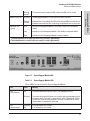
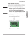
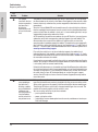
Figure 1-6. Management Module LEDs
Table 1-3.
Management Module LEDs.
LED
State
Meaning
Auxiliary (green/
orange) For more
information see the
Management and
Configuration Guide
for your switch.
Blinking
green1
Indicates the switch is processing a USB command file.
On green
The switch has finished processing the USB command file successfully.
Blinking
orange2
Indicates an error condition.
Off
Indicates that no USB device has been inserted, or that the inserted USB device
cannot be recognized, or that no command file can be found on the inserted USB
device.
On green
DIM (Dual in-line Memory Module) status is known and fault free.
Off
DIM status is unknown.
Blinking
orange1
If DIM, Fault, and Self Test LEDs are blinking, DIMM failed self-test.
If DIM and Fault LEDs are blinking, an operational fault has occurred.
If fast blinking (400ms On and 400ms Off), an operational alert occurred and is
unresolved.
On green
CF (CompactFlash) status is known and fault free
Off
CF status is unknown.
Blinking
orange1
If CF, Fault, and Self Test LEDs are blinking, CompactFlash failed self-test.
If CF and Fault LEDs are blinking, an operational fault has occurred.
If fast blinking (400ms On and 400ms Off), an operational alert occurred and is
unresolved (for example, CompactFlash not present).
On green
The communication link with the SSM (system support module) is good.
Off
The communication link with the SSM is bad or there is no SSM installed.
DIM
(green/orange)
CF
(green/orange)
SSM
(green/orange)
1-8
Introducing the HP 8200 zl Switches
Front of the 8200 zl Switches
MM State LEDs
(green)(
The communication link with the SSM is bad or the SSM itself has failed.
On green
The Management Module is active and has passed all self-tests.
Blinking
orange1
If Module Status, Fault and Self Test LEDs are blinking, this MM has failed self-test
If Module Status and Fault LEDs are blinking, an operational fault has occurred.
Actv
Indicates the Management Module is active and is the primary management
module.
Stby
Indicates that this Management Module is the standby management module.
Dwn
Indicates that this Management Module has been shutdown.
1 The blinking behavior is an on/off cycle once every 1.6 seconds, approximately.
2 The blinking behavior is an on/off cycle once every 0.5 seconds, approximately.
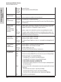
Figure 1-7. System Support Module LEDs
Table 1-4.
System Support Module LEDs
These LEDs are located on the System Support Module.
LED
State
Meaning
Test
(green/orange)
Off
The normal operational state; the switch is not undergoing self test.
On green
The switch self test and initialization are in progress after you have power cycled
or reset the switch. The switch is not operational until this LED goes off. The Self
Test LED also comes on briefly when you “hot swap” a module into the switch
and the module is automatically self tested.
On green
Off
If any PoE modules are installed.
If no PoE modules are installed.
PoE
(green/orange)
1-9
Introducing the HP 8200 zl
Switches
Module Status LED
Blinking
orange1
Introducing the HP 8200 zl
Switches
Introducing the HP 8200 zl Switches
Front of the 8200 zl Switches
Blinking
orange1
Blinking
orange2
Internal PoE fault.
External load fault or denied PoE power.
Tmp
(green/orange)
Off
Switch temperature is normal.
Blinking1
An over temperature condition has been detected.
Fan
(green/orange)
On green
The cooling fans are operating normally.
Blinking
orange1
One or more of the cooling fans have failed. The switch Fault LED will be blinking
simultaneously.
Internal Power 1-4
(green/orange numbers
corresponding to
the power supply
positions)
On green
A power supply is installed in the position in the back of the switch corresponding
to the number, and the supply is plugged in to an active AC power source. As
shipped, the switch has a single power supply in position 1.
Off
A power supply is not installed in the position corresponding to the number.
Blinking
orange1
The power supply installed in the position corresponding to the number is not
plugged in to an active AC power source, or has experienced a fault. The switch
Fault LED will be blinking simultaneously.
EPS (1 and 2)
(green/orange)
On green
Off
An External Power Supply is connected.
No External Power Supply is connected.
Blinking
orange1
The External Power Supply has a fault, or is connected but not plugged into AC
power.
On green
Off
A Fabric Module is installed and functioning correctly.
A Fabric Module is not installed or has failed.
Blinking
orange1
The Fabric Module has a fault.
The switch Fault LED will be blinking simultaneously.
Act
Indicates that the port Mode LEDs are displaying network activity information.
FDx
Indicates that the port Mode LEDs are lit for ports that are in Full Duplex Mode.
PoE
Indicates which ports are supplying PoE power.
• If the Mode LED is on the port is providing PoE power.
• If the Mode LED is off the port is not providing PoE power.
• If the Link LED is on the port is enabled for PoE.
• If the Link LED is off the port is disabled for PoE.
• If the Link LED is blinking, the port has an error or the port is denied power due
to insufficient power.
Spd
Indicates the Port LEDs are displaying the connection speed at which each port
is operating:
• if the Port LED is off, the port is operating at 10 Mbps
• if the Port LED is blinking, the port is operating at 100 Mbps
• if the Port LED is on continuously, the port is operating at 1000 Mbps
Usr
Reserved for future development
Fabric Modules
(1 and 2)
(green/orange)
LED Mode Select
(5 green LEDs)
1-10
Introducing the HP 8200 zl Switches
Front of the 8200 zl Switches
In PoE Mode:
On
A module is installed in the switch module slot corresponding to the letter and
the module is undergoing or has passed self test. This also occurs when you
install a module when the switch is already powered on (“hot swap”).
Off
A module is not installed in the switch module slot corresponding to the letter.
Blinking1
The module status LED flashes very briefly when a module is being hot swapped.
If the LED flashes for a prolonged time, the module in the slot corresponding to
the letter has failed self test or encountered some other fault condition. See
chapter 5, “Troubleshooting” for a more information.
On green
Blinking
orange1
Blinking
orange2
Off
PoE is ok for this slot.
PoE internal fault for this slot.
PoE load fault or insufficient power for this slot.
The module in this slot is not a PoE module.
1 The blinking behavior is an on/off cycle once every 1.6 seconds, approximately.
2 The blinking behavior is an on/off cycle once every 0.5 seconds, approximately.
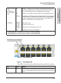
Switch Modules with Link and Mode LEDs
for each port located on each module
Figure 1-8. Switch Module LEDs
Table 1-5.
Switch Module LEDs
These LEDs are located on the modules themselves, one pair for each port.
LED
State
Meaning
Link
On
Indicates the port is enabled and receiving a link beat signal (for the twisted-pair
ports), or a strong enough light level (for the fiber-optic ports) from the connected
device.
1-11
Introducing the HP 8200 zl
Switches
Modules A-L (green
- letters
corresponding to
the switch module
slots)
Introducing the HP 8200 zl
Switches
Introducing the HP 8200 zl Switches
Front of the 8200 zl Switches
Mode
Off
One of these conditions exists:
• no active network cable is connected to the port
• the port is not receiving link beat or sufficient light
• the port has been disabled through the switch console, the web browser
interface, ProCurve Manager, or other network management tool.
Blinking1
The port has failed self test. The switch Fault, Self Test LEDs, and appropriate
module status LEDs will flash simultaneously.
Depending on the mode selected, displays the following: network activity information, whether
the port is configured for Full Duplex operation, maximum speed operation, or whether PoE
power is being supplied or not. See “LED Mode Select Button and Indicator LEDs” below for
more information.
1 The blinking behavior is an on/off cycle once every 1.6 seconds, approximately.
LED Mode Select Button and Indicator LEDs
To optimize the amount of information that can be displayed for each of the
switch ports, the 8200 zl switches use a Mode LED for each port. The operation
of this LED is controlled by the LED Mode Select button on the switch chassis,
and the current selection is indicated by the mode indicator LEDs near the
button. Press the button to change from one mode to the next.
LED Mode Select button
and indicator LEDs
Mode LEDs
(Link and Mode)
Figure 1-9. Mode LEDs and LED Mode Select Button
■
■
1-12
If the Activity Act indicator LED is lit, each port Mode LED displays
activity information for the port—it flickers as network traffic is received
and transmitted through the port.
If the Full Duplex FDx indicator LED is lit, the port Mode LEDs light for
those ports that are operating in full duplex.
Introducing the HP 8200 zl Switches
Front of the 8200 zl Switches
■
Mode LED:
• On = PoE power is be supplied on this port
• Off = PoE is not being supplied on this port.
Console Port
This port is used to connect a console to the switch by using the serial cable
supplied with the switch. This connection is described under “Connecting a
Console to the Switch” in chapter 2, “Installing the the 8200 zl Switch”. The
console is a full-featured interface that can be used to configure, monitor, and
troubleshoot the switch. It can be run on a PC, laptop, or handheld device
emulating a VT-100 terminal, or on a standard VT-100 terminal.
Reset Buttons
Module Reset
This button, located on the Management module, will reset the Management
module only.
System Reset
This button, located on the System Support Module, will reset the switch when
powered on. This action clears any temporary error conditions that may have
occurred, executes the switch self test, and resets all network activity counters to zero.
The counters are displayed in the switch console interface, the switch web
browser interface, and through SNMP network management applications,
such as ProCurve Manager.
1-13
Introducing the HP 8200 zl
Switches
■
If the speed Spd indicator LED is lit, the port LEDs behave as follows to
indicate the connection speed for the port:
• Off = 10 Mbps
• Blinking = 100 Mbps (the blinking behavior is a repeated on/off cycle
once every 0.5 sec.)
• On = 1000 Mbps
If the PoE indicator LED is lit, the Link and Mode LEDs indicate PoE status:
Link LED:
• On = PoE is enabled on this port
• Off = PoE is disabled on this port.
• Slow Blinking = Internal PoE fault on this port.
• Fast Blinking = This port is denied PoE power or has an external load
fault.
Introducing the HP 8200 zl Switches
Front of the 8200 zl Switches
Introducing the HP 8200 zl
Switches
Press the Reset button also after changing the module type that is installed in
any of the switch module slots while the switch is powered on. In this case,
the switch must be reset to initialize the new module type. See “Hot Swapping
Switch Modules” on page 2-30.
Clear Button
This button, located on the System Support Module, is used for the following
purposes:
■
Deleting Passwords - When pressed by itself for at least one second, the
Clear button deletes any switch console access passwords that you may
have configured. Use this feature if you have misplaced the password and
need console access.
■
1-14
This button is provided for your convenience, but its presence means that
if you are concerned with the security of the switch configuration and
operation, you should make sure the switch is installed in a secure
location, such as a locked wiring closet.
Restoring Factory Default Configuration - When pressed with the
Reset button in a specific pattern, the Clear button clears any configuration changes you may have made through the switch console, the web
browser interface, or SNMP management, and restores the factory default
configuration to the switch. For the specific method to restore the factory
default configuration, see “Restoring the Factory Default Configuration”
in chapter 5, “Troubleshooting” of this manual.
Introducing the HP 8200 zl Switches
Back of the 8200 zl Switches
Introducing the HP 8200 zl
Switches
Back of the 8200 zl Switches
Back of the 8212 zl Switch
Grounding lug
mounting holes
Fan Power, Fault
and Locator LEDs
Slots for installing power
supplies
External PoE
power connectors
Figure 1-10. Back of an 8212 zl Switch
1-15
Introducing the HP 8200 zl Switches
Back of the 8200 zl Switches
Introducing the HP 8200 zl
Switches
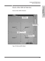
Back of the 8206 zl Switch
Grounding lug
mounting holes
Power supply
Optional redundant power
supply
External PoE/
PoE+ power
connectors
Figure 1-11. Back of an 8206 zl Switch (shown with two zl Power Supplies)
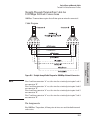
Power Supply
The 8200 zl switches do not have a power switch. The switches are powered
on when the power supply is connected to an active AC power source. The
8200 zl switches automatically adjust to any voltage between 100-127 and 200240 volts when using the J8712A power supply, between 110-127 and 200-240
volts when using the J9306A power supply, and between only 200-240 volts
when using the J8713A power supply. There are no voltage range settings
required.
1-16
Introducing the HP 8200 zl Switches
Switch Accessories
Caution
The switch redundant power supply is hot swappable, but, as indicated by the
caution statement on the power supply, it must be disconnected from AC
power before being installed or removed.
CAUTION:
. Refer to the installation guide for proper power cord selection
.Disconnect AC power from the power supply BEFORE installing or
removing the supply. Otherwise, damage to the. equipment may result.
Because the switch can run on a single supply, removing a redundant supply
will not interrupt switch operation. However, on the 8212 zl, one power supply
will only supply enough power to run the module slots A-F. Slots G-L will not
receive any power unless there are at least two power supplies installed.
When power is restored from a second (or more) power supplies, a system
reload or interface module reset is required to restore operation to slots G-L.
To reset the interface modules, pull each module out about half way and then
reseat them. Do this for each module in slots G-L.
For more information regarding power see the:
■
ProCurve Switch zl Internal Power Supply Installation Guide.
■
HP Power over Ethernet (PoE/PoE+) Planning and Implementation
Guide.
Switch Accessories
Accessories of the 8200 zl switches include either a 6 or 12-slot chassis for
installing any of the available zl Modules. The supported zl modules include:
■
24-Port 10/100/1000 PoE+ zl Module (J9307A) -- which can provide Power
over Ethernet (PoE+) power to 802.3at compliant (and some pre-standard) devices.
■
20-Port 10/100/1000 PoE+/4-Port MiniGBIC zl Module (J9308A)
■
4-Port 10GbE SFP+ zl Module (J9309A)
■
24-Port 10/100 PoE+ zl Module (J9478A)
1-17
Introducing the HP 8200 zl
Switches
Load-sharing redundant power supplies can be installed in the back of the
8200 zl switches or they can be installed externally with the external power
connectors. To provide redundancy, each power supply should be connected
to different AC power sources. Then, if one AC power source fails, the switch
will continue to run.
Introducing the HP 8200 zl Switches
Switch Accessories
Introducing the HP 8200 zl
Switches
■
■
■
■
■
■
■
■
■
■
■
■
■
■
■
■
■
■
■
Note
24-port 10/100/1000-T zl PoE Module (J8702A) -- which can provide Power
over Ethernet (PoE) power to 802.3af compliant (and some pre-standard)
devices.
20-port Gig-T and 4-port mini-GBIC/SFP zl PoE Module (J8705A)
24-port mini-GBIC zl Module (J8706A)
4-port 10Gig-X2 zl Module (J8707A)
4-port 10Gig-CX4 zl Module (J8708A)
ONE Services zl Module (J9289A)
Redundant Wireless Services zl Module (J9052A)
Wireless Edge Services zl Module (J9154x) where “x” is the version letter
A, B, and so on
24-port Gig-T PoE+ v2 zl Module (J9534A)
20-port GT PoE+/4-port SFP v2 zl Module (J9535A)
20-port Gig-T PoE+ / 2-port 10-GbE SFP+ v2 zl Module (J9536A)
24-port SFP v2 zl Module (J9537A)
8-port 10-GbE SFP+ v2 zl Module (J9538A)
8-port 10GBase-T v2 zl Module (J9546A)
24-port 10/100 PoE+ v2 zl Module (9547A)
20-port Gig-T / 2-port 10-GbE SFP+ v2 zl Module (J9548A)
20-port Gig-T / 4-port SFP v2 zl Module (J9549A)
24-port Gig-T v2 zl Module (J9550A)
12-port Gig-T / 12-port SFP v2 zl Module (J9637A)
For detailed information about the zl modules, refer to the HP Switch zl
Modules Installation Guide.
For detailed information about PoE and PoE+ devices, refer to the HP Power
over Ethernet (PoE/PoE+) Planning and Implementation Guide.
To view or download this guide, visit www.hp.com/networking/support.
1-18
Introducing the HP 8200 zl Switches
Switch Features
The features of the 8200 zl switches include:
■
modules can be installed in any order and in any combination and can be
“hot swapped”
■
supported transceivers can be hot swapped into the mini-GBIC zl Module
■
high performance—With standard zl modules, the 8206 zl Switch has a
routing/switching capacity of 322.8 Gbps, with a switch fabric speed of
345.6 Gbps and a throughput of 240.2 Mpps. With standard zl modules, the
8212 zl Switch has a routing/switching capacity of 645.6 Gbps, with a
switch fabric speed of 691.2 Gbps and a throughput of 480.3 Mpps
■
■
■
■
■
With v2 zl modules, the 8206 zl Switch has a routing/switching capacity of
496.8 Gbps, with a switch fabric speed of 561.6 Gbps and a throughput of
396 Mpps. With v2 zl modules, the 8212 zl Switch has a routing/switching
capacity of 993.6 Gbps, with a switch fabric speed of 1123.2 Gbps and a
throughput of 792 Mpps
plug-and-play networking—all ports are enabled—just connect the
network cables to active network devices and your switched network is
operational
automatic learning of the network addresses in the switch’s 16,000address forwarding table, with configurable address aging value
full-duplex operation available on all ports
easy management of the switch through several available interfaces:
• web browser interface—an easy to use built-in graphical interface
that can be accessed from common web browsers
• console interface—a full featured, easy to use, VT-100 terminal interface for out-of-band switch management, or for TELNET access to
the switch. The console includes complete switch management
through a command line interface (CLI) and a slightly reduced feature
set accessible through an intuitive menu interface
• ProCurve Manager—an SNMP-based graphical interface that is used
to manage your entire network, included with your new switch
• supported by ProCurve Network Manager—an HP OpenView application that accurately displays your switch on network maps and
provides a graphical interface for configuring and monitoring your
switch
support for the Spanning Tree Protocol to eliminate network loops
1-19
Introducing the HP 8200 zl
Switches
Switch Features
Introducing the HP 8200 zl Switches
Switch Features
Introducing the HP 8200 zl
Switches
■
■
■
■
1-20
support for up to 2048 VLANs (up to 512 layer-3, IP addressable VLANs)
so you can divide the attached end nodes into logical groupings that fit
your business needs
Layer 3 routing functionality:
• IP static routes
• RIP V1 and V2
• IRDP - ICMP Router Discovery Protocol
• OSPF- Open Shortest Path First
• DHCP relay
support for many other advanced features to enhance network performance, security, and control— for a description, see the Management and
Configuration Guide which is on the HP networking Web site.
support for IEEE 802.3af standard, IEEE 802.3at standard, and pre-standard PoE devices
2
Installing the HP 8200 zl Switches
The 8200 zl switches are easy to install. Each comes with an accessory kit that
includes the brackets for mounting the switch in a standard 19-inch telco rack,
or in an equipment cabinet. The switch has rubber feet already attached so
they can be securely located on a horizontal surface. This chapter tells you
how to install your 8212 zl or 8206 zl switch.
To avoid possible personal injury, be careful when lifting the chassis
out of the shipping box. The Switch 8212 zl chassis base system weighs
approximately 50.45 pounds as shipped and 44.75 pounds when empty.
See “Installation Precautions” on page 2-5 for additional safety
considerations when handling this product.
Included Parts
The following components are shipped with the 8200 zl switches:
■
HP 8212 zl Quick Setup Guide or HP 8206 zl Quick Setup Guide
■
HP 8200 zl Safety and Regulatory Information
■
Accessory kit (5070-6865 for the 8206 zl or 5070-2983 for the 8212 zl):
• two mounting brackets
• eight 10 mm M4 screws to attach the mounting brackets to the switch
• eight 5/8-inch number 12-24 screws to attach the switch to a rack
■
Console cable
2-1
Installing the HP 8200 zl
Switches
WARNING
Installing the HP 8200 zl Switches
Power Cords
Power Cords
Note
Power supplies for 8200 zl Switches must be ordered separately. The following
power cords are provided with those power supplies.
Power cord, one of the following:
Installing the HP 8200 zl
Switches
Region
Australia/New Zealand
China
Continental Europe
Denmark
Japan
Switzerland
United Kingdom/Hong Kong/Singapore
United States/Canada/Mexico
South Africa
Taiwan
Israel
Thailand
Argentina
Brazil
Chile
Japan Power
Cord Warning
2-2
J8712A Power
Supply
J8713A Power
Supply
J9306A Power
Supply
Cable
Cable
Cable
8121-0857
8121-1034
8120-5336
8120-5340
8120-5342
8120-5339
8120-5334
8121-0973
8120-5341
8121-0941
8121-1009
8121-0671
8120-8375
8121-1132
8120-8389
8121-0871
8121-0924
8120-6899
8120-6897
8120-6903
8120-6897
8120-6898
8120-6903
8121-0915
8120-6903
8121-1010
8121-0675
8121-0912
8121-1100
8121-0876
8121-0857
8121-1034
8120-5336
8120-5340
8121-09411
8120-5339
8120-5334
8121-09732
8120-5341
8121-0967
8121-1009
8121-0671
8120-8375
8121-1132
8120-8389
1
Japan: NEMA L6-20P, 200V.
2
A NEMA L6-20, 240V power cord is also available. Order part number 8121-0941. To
order go to www.hp.com/buy/parts.
Installing the HP 8200 zl Switches
Installation Procedures
Installation Procedures
WARNING
To avoid personal injury or product damage, read the safety warnings
on page 2-5 and installation precautions on page 2-6 and follow the
rack mounting guidelines on page 2-7. Due to product weight, two or
more persons are required to handle and mount the 8212 zl.
Summary
1.
Prepare the Installation Site (page 2-7). Make sure the physical
environment into which you will be installing the switch is properly
prepared including having the correct network cabling ready to connect
to the switch, and having a good location for the switch.
2.
Mount the Switch Chassis (page 2-7). The 8200 zl switches are large,
heavy chassis. HP networking recommends mounting the empty chassis
before populating it with modules or power supplies. It can be mounted
in a 19-inch telco rack, in an equipment cabinet, or on a horizontal surface.
An optional Rail Mounting Kit (5070-0145) is available for mounting the
8200 zl switches in a cabinet that is suitable for shipping.
3.
Install the Switch Modules (page 2-11). The 8200 zl switches have
either six or twelve universal slots for installing any of the HP zl Modules.
Depending on where you will install your 8200 zl switch, it may be easier
to install the modules first. The modules are “hot swappable” though, so
they may also be installed and removed after the switch is powered on.
4.
Install the Power Supplies (page 2-14). The 8212 zl switch supports
four power supplies. The 8206 zl switch supports two power supplies. It
may be easier to install the power supplies before mounting the switch.
The switch must have at least one power supply to operate some of the
modules.
5.
Verify the Switch Passes Self Test (page 2-17). This is a simple process
of plugging the switch into a power source and observing that the LEDs
on the switch’s front panel and on the modules show correct operation.
It may be easier to verify if the switch passes self test before mounting
the switch.
2-3
Installing the HP 8200 zl
Switches
Follow these easy steps to install your switch. The rest of this chapter provides
details on these steps.
Installing the HP 8200 zl
Switches
Installing the HP 8200 zl Switches
Installation Procedures
Note
6.
Install the Grounding Wire (page 2-20). If a grounding wire is to be
attached to the switch chassis, the grounding lug must be removed and a
wire crimped to it and the grounding lug must be reinstalled.
7.
Connect the Switch to a Power Source (page 2-21). Once the switch
is mounted, plug it in to the nearby main power source.
8.
(Optional) Connect a Power Supply Shelf (page 2-21). You may wish
to use a Switch zl Power Supply Shelf (J8714A) with your switch. To do
so, you must connect the external power supply using the EPS cables
supplied with the Power Supply Shelf.
9.
Connect the Network Devices (page 2-25). Using the appropriate
network cables, connect other switches, hubs, routers, computers,
servers, printers, and other network devices to the switch ports. For more
information, see “Connect the Network Devices” on page 2-25.
The 10/100/1000-T ports on the zl Modules comply with IEEE 802.3x
standard which includes the Auto MDI/MDI-X feature. This feature
allows you to use straight-through twisted-pair cable for all of your
twisted-pair network connections.
10. (Optional) Connect a Console to the Switch (page 2-27). You may
wish to modify the switch’s configuration, for example, to configure an IP
address so it can be managed using a web browser or from an SNMP
network management station. Configuration changes can be made easily
through the switch’s console interface.
At this point, the switch is fully installed. See the rest of this chapter if you
need more detailed information on any of these installation steps.
2-4
Installing the HP 8200 zl Switches
Installation Procedures
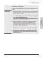
Installation Precautions
To prevent personal injury, follow these precautions when installing the 8212
zl switch:
WARNINGs
Due to product weight, two or more persons are required to handle
and mount the 8212 zl switch. To reduce the weight, remove all
modules and power supplies.
■
Devices installed in a rack or cabinet should be mounted as low
as possible, with the heaviest device at the bottom and progressively lighter devices installed above.
The rack or cabinet should be adequately secured to prevent it
from becoming unstable and/or falling over.
■
Ensure a cover plate is installed on any empty switch power
supply or module slot. A cover plate is required for safe
operation, and to ensure proper switch cooling. Never have
more than one power supply or module slot uncovered at a
time while the switch is powered on.
■
To avoid energy and mechanical hazards, never allow any part
of your body, jewelry, tool, or other foreign object to enter any
module or power supply slots.
■
This unit may have more than one power supply cable. To fully
power down the switch, you must disconnect all power supply
cables from the unit.
2-5
Installing the HP 8200 zl
Switches
■
Installing the HP 8200 zl Switches
Installation Procedures
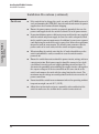
Installation Precautions (continued)
Installing the HP 8200 zl
Switches
Cautions
2-6
■
If the switch is to be shipped in a rack, use only an HP 10000 series rack
and a rail mounting kit (5070-0145) for each switch and ensure the power
supplies have been removed before shipping.
■
Ensure the power source circuits are properly grounded, then use the
power cord supplied with the switch to connect it to the power source.
■
If your installation requires a different power cord than the one supplied
with the switch and power supply, be sure the cord is adequately sized
for the switch’s current requirements. In addition, be sure to use a power
cord displaying the mark of the safety agency that defines the regulations
for power cords in your country. The mark is your assurance that the
power cord can be used safely with the switch and power supply.
■
When installing the switch, note that the AC outlet should be near the
switch and should be easily accessible in case the switch must be
powered off.
■
Ensure the switch does not overload the power circuits, wiring, and overcurrent protection. Each power supply should be connected to a dedicated branch circuit to prevent tripping building circuit breakers. To
determine the possibility of overloading the supply circuits, add together
the ampere ratings of all devices installed on the same circuit as the
switch and compare the total with the rating limit for the circuit. The
maximum ampere ratings are usually printed on the devices near the AC
power connectors.
■
Do not install the switch in an environment where the operating ambient
temperature might exceed 45C (113F).
■
Allow three to four inches of space around the sides and back of the
switch to make sure the air flow for the switch is not restricted.
Installing the HP 8200 zl Switches
Installation Procedures
1. Prepare the Installation Site
Cabling Infrastructure
Ensure the cabling infrastructure meets the necessary network specifications.
See Appendix C, “Cabling and Technology Information” on page B-1 for more
information.
Installation Location
Before installing the switch, plan its location and orientation relative to other
devices and equipment:
In the front of the switch, allow at least 7.6 cm (3 inches) of space for the
twisted-pair and fiber-optic cabling.
■
In the back of the switch, allow at least 10.2 cm (4 inches) of space for the
power cord and cooling.
■
On the sides of the switch, leave at least 7.6 cm (3 inches) for cooling.
2. Mount the Switch Chassis
The HP 8200 zl switches have large, heavy chassis; therefore, HP networking
recommends mounting the switch before populating it with modules or power
supplies.
WARNING
A base system weighs approximately 50 pounds, and an unloaded
chassis weighs approximately 44 pounds. To avoid personal injury, plan
on having at least two people available to help move the unit into place
onto the rack. TWO OR MORE PEOPLE ARE REQUIRED WHEN
MOUNTING THIS SWITCH.
The 8200 zl switches can be mounted in these ways:
■
in a rack or cabinet
■
on a horizontal surface
Rack or Cabinet Mounting
The 8200 zl switches are designed to be mounted in any EIA-standard
19-inch telco rack or in an equipment cabinet such as a server cabinet. If you
are installing the switch in an equipment cabinet, read the following “Equipment Cabinet Note” on page 2-8.
2-7
Installing the HP 8200 zl
Switches
■
Installing the HP 8200 zl Switches
Installation Procedures
Equipment
Cabinet
Note
If you are installing the switch in an equipment cabinet, in place of the 1224 screws supplied with the switch, use the clips and screws that came with
the cabinet. Plan which four holes you will be using in the cabinet and install
all four clips and partially install the two bottom screws, as described in step
2 on the previous page, before proceeding to step 3.
WARNING
For safe operation, please read the “Installation Precautions” on page
2-5 and page 2-6 before mounting the switch.
Installing the HP 8200 zl
Switches
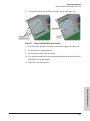
1.
Use a #1 Phillips (cross-head) screwdriver and attach the mounting
brackets to the switch with the included 8-mm M4 screws.
For the 8200 zl switches, each bracket is attached with four screws as
shown in the following illustrated example.
8 mm
M4 screws
Figure 2-1. Attaching Brackets to the 8212 zl Switch
2-8
Installing the HP 8200 zl Switches
Installation Procedures
2.
Partially install a screw into the top hole of a pair of holes that are 0.5
inches apart in each rack/cabinet upright as shown in the illustration
below. Ensure that the screws are at the same level in each upright.
Partially install a screw
into the top hole of a
close (0.5-inch) pair on
both sides of the rack
Installing the HP 8200 zl
Switches
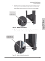
Figure 2-2. Mounting Screw Positioning
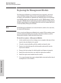
3.
Place the switch in the rack and lower it so the notches in the bottom of
the bracket slide onto the screws, then tighten these screws.
lower the switch with
mounting brackets onto the
partially installed screws,
then tighten these screws
Figure 2-3. Notches in Bracket Being Installed
2-9
Installing the HP 8200 zl Switches
Installation Procedures
4.
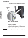
Install the other screw into the upper hole in each bracket. Tighten these
screws.
Installing the HP 8200 zl
Switches
install and tighten the
other 12-24 screws
Figure 2-4. Screws in Bracket Being Installed
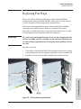
Horizontal Surface Mounting
Place the switch on a table or other horizontal surface. Use a sturdy surface
in an uncluttered area. You may want to secure the networking cables and
switch power cord to the table legs or other part of the surface structure to
help prevent people from tripping over the cords.
Note
2-10
Ensure the air flow is not restricted around the sides and back of the switch.
Installing the HP 8200 zl Switches
Installation Procedures
3. Install the Switch Modules
Install switch modules into the slots as shown in the illustration below. For
installation details, see the instructions in the manual that comes with the
module.
Caution
Make sure you install only HP Switch zl Modules.
Avoid any electrostatic discharge problems by handling the modules only by
their bulkheads.
Module
Installation
Notes
■
Any of the supported Switch zl Modules can be installed in any of the slots.
■
The modules can be “hot swapped”, installed after the switch is already
powered on, and normally will be immediately operational. But, if you are
replacing a module with a different type than what was previously
installed in the slot, the switch must be rebooted after the module is
installed. See “Hot Swapping the Switch Module” on page 2-30.
■
Ensure you fully insert the modules. That is, press the module into
the slot using the extractor handles, until the bulkhead on the module is
contacting the front face of the switch chassis.
■
Once the module is fully inserted, screw in the two retaining screws to
secure the module in place. The screws should be tightened until they are
secure, but not overtightened.
■
If you do not use one or more of the slots, ensure the slot cover plate is
still attached over the slot for safe operation and proper switch cooling.
For safety, you should not have more than one module slot uncovered at
a time.
■
Although these procedures show the 6-slot chassis, the procedures are
the same for the 12-slot chassis.
2-11
Installing the HP 8200 zl
Switches
The slot cover can be removed, and the module can be installed with either a
flat-bladed or Torx T-10 screwdriver. Retain the slot cover for future use.
Installing the HP 8200 zl Switches
Installation Procedures
Installing the HP 8200 zl
Switches
Insert module into the guides and
slide it in until it is fully inserted.
Open extractor handles
Figure 2-1. Module Being Installed in a Chassis
Use the extractor handles to
seat the module completely.
Then tighten the retaining screws
on the module until they are secure,
but do not overtighten them.
Figure 2-5. Chassis with Module Fully Installed
2-12
Installing the HP 8200 zl Switches
Installation Procedures
Installing a Management Module Battery
The battery on the management module is used to keep time for the internal
switch clock. There is no indicator LED for when the battery dies. The only
indication will be the internal clock will not keep the correct time.
WARNING
■
■
To install a New Battery:
1.
Insert the new battery with the lettering and the plus “+” sign facing up.
2.
Install the management module into the switch.
Figure 2-6. Battery Location on Management Module
2-13
Installing the HP 8200 zl
Switches
■
The battery requires special handling at end-of-life. The battery
can explode or cause burns if disassembled, charged, or exposed
to water, fire or high temperature. After replacing the battery,
properly dispose of used battery according to instructions.
There is a risk of explosion if the battery is replaced by an
incorrect type. Ensure to replace the battery with the same type.
To avoid shorting of battery, remove and properly dispose of
battery before returning the Management Module for repair.
Installing the HP 8200 zl Switches
Installation Procedures
AT T E N T I O N
ll y a danger d'explosion s'il y a remplacement incorrect de la batterie.
Remplacer uniquement avec une batterie du même type ou d'un type
équivalent recommandé par le constructeur.
Mettre au rebut les batteries usagées conformément aux instructions du
fabricant.
Installing the HP 8200 zl
Switches
AT T E N T I O N
If this product contains a real-time clock battery or coin cell battery it may
contain perchlorate and may require special handling when recycled or
disposed of in California and other certain states.
Perchlorate material - special handling may apply see:
www.dtsc.ca.gov/hazardouswaste/perchlorate Web site for more
information.
4. Install the Power Supplies
Both the 8212 zl switch and the 8206 zl switch can use any of these HP switch
zl power supplies:
Caution
■
The J9306A, 1500W PoE+ zl Power Supply, which delivers the following
PoE+:
• up to 300 watts at 110-127 volts
• up to 900 watts at 200-240 volts
■
The J8712A, 875 W Power Supply, which delivers up to 273 watts of PoE
power.
■
The J8713A, 1500 W Power Supply, which delivers up to 900 watts of PoE
power at 220 volts.
The J8712A and J8713A power supplies can be paired within the same switch
or within the Power Supply Shelf. However, the J9306A power supply can only
be paired with another J9306A power supply within the same switch or within
the Power Supply Shelf. The J9306A power supply cannot be used with either
the J8712A or J8713A power supplies.
The HP 8212 zl switch has limited operation on a single power supply. Only
the first six module slots (A-F) will be powered when using only one power
supply. In order to power all 12 module slots, the 8212 zl switch requires two
2-14
Installing the HP 8200 zl Switches
Installation Procedures
power supplies installed in the switch. When there are two power supplies
installed in the switch and one should fail, the other power supply can keep
the switch running with the first six module slots operational. The 8212 zl
switch can hold up to four, load-sharing power supplies. Install the second
power supply into power slot number 2, as shown in Figure 2-3. Be sure to use
the same power supplies in any one switch.
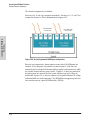
The HP 8206 zl switch has full operation on a single power supply. However,
a second, redundant power supply will prevent the switch from losing all
operation should the main power supply fail. The 8212 zl can hold up to two,
load-sharing power supplies. Be sure to use the same power supply model in
any one switch.
To prevent overloading of the building circuits, the second power supply can
be connected to a different AC power source than the first power supply. This
also helps with redundancy where in the event of one power source failure,
the switch will continue to operate.
Caution
The 8200 zl switches are designed to provide continuously operating PoE or
PoE+ power in the event of a single power supply failure with only a loss of
PoE power to lower priority ports.
If more than one power supply fails while the switch is at or near maximum
operating power (that is: the sum total of all PoE or PoE+ supply capacity
minus the largest supply, see chapter 2 and 4 of the HP Power over Ethernet
(PoE/PoE+) Planning and Implementation Guide) loss of all PoE or PoE+
power may result.
To return PoE or PoE+ power to the ports without causing the switch to
reboot, when there are two or more power supplies still supplying 12V power,
unplug the power cord for 5 seconds and re-plug it for each power supply one
at a time.
2-15
Installing the HP 8200 zl
Switches
The power supply slot covers can be removed with either a flat-bladed or Torx
T-10 screwdriver. Retain the slot covers for future use.
Installing the HP 8200 zl Switches
Installation Procedures
Caution
The switch power supplies are hot swappable; they can be installed while the
switch is receiving power from the supply in the other slot. But, as indicated
by the caution statement on the power supply, the supply must not be
connected to AC power before being installed or removed.
CAUTION:
. Refer to the installation guide for proper power cord selection
.Disconnect AC power from the power supply BEFORE installing or
removing the supply. Otherwise, damage to the. equipment may result.
Installing the HP 8200 zl
Switches
For safety and proper switch cooling, if either of the power supply slots are
not being used, make sure to attach the cover plate over the slot. Please see
the “Installation Precautions” on page 2-6 for more information.
For installation details, see the instructions in the manual that comes with the
power supply.
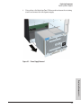
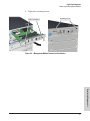
Insert the power supply into the
opening, then slide it all the way in
until it connects to the switch. The
power supply face plate will be
flush with the back face of the
switch.
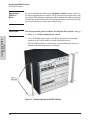
Figure 2-7. Installing a Power Supply
2-16
Installing the HP 8200 zl Switches
Installation Procedures
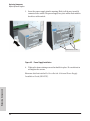
Once the power supply is installed, tighten the four retaining screws that hold
it in place. The screws can be tightened with either a flat-bladed or Torx T-10
screwdriver. Be careful not to overtighten the screws.
tighten the four screws
Installing the HP 8200 zl
Switches
Figure 2-8. Back of Switch with Power Supply Fully Installed
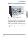
5. Verify the Switch Passes Self Test
After you have installed any modules and the optional second power supply,
but before mounting the switch in its network location, you should first verify
it is working properly by plugging it into a power source and verifying it passes
its self test.
If you have installed a second power supply, repeat these procedures with the
second power supply to verify it works correctly also.
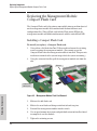
1.
Connect the power cord supplied with the switch to the power connector
on the back of the switch, and then into a properly grounded electrical
outlet.
2-17
Installing the HP 8200 zl
Switches
Installing the HP 8200 zl Switches
Installation Procedures
Connect power cord to
power connector
Figure 2-9. Power Connector on Back of Switch
Note
The 8200 zl switches do not have a power on-off switch. It is powered on when
the power cord is connected to the switch and to a power source.
If your installation requires a different power cord than the one supplied with
the switch, please see the “Installation Precautions” on page 2-6.
2.
Check the LEDs on the switch and on each of the switch modules. The
LED behavior is described on the next page.
If the LED display is different than what is described, especially if the
Fault LED stays on for more than approximately 120 seconds or it starts
blinking, the self test has not completed correctly. Refer to chapter 5,
“Troubleshooting” for diagnostic help.
2-18
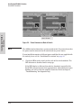
Installing the HP 8200 zl Switches
Installation Procedures
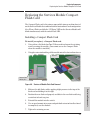
Switch Chassis LEDs
Switch Fault LED
Switch Module LEDs:
Link and Mode LEDs
for each port
Installing the HP 8200 zl
Switches
Figure 2-10. Switch Fault, Module, and Chassis LEDs
When the switch is powered on, it performs its diagnostic self test. The entire
download, initialization, and self test process can take up to 2 minutes for a
fully loaded chassis, depending on the number and type of modules installed
in the switch.
LED Behavior:
During the self test:
■
Initially, Power, Fault, Locator, and all the switch chassis LEDs are on. Then,
after approximately 30 seconds, all the module LEDs go on as the modules
receive power and code is downloaded to them, the Fault LED goes off,
and the chassis LEDs turn orange and then go off except Test, Fan, and
Power, which turn green.
■
When the download of code to the modules is completed, the module
LEDs go off. You may see each port LED go on briefly, in sequence, as the
port is tested.
■
For the duration of the self test, the Test LED stays on.
2-19
Installing the HP 8200 zl Switches
Installation Procedures
Installing the HP 8200 zl
Switches
When the test completes successfully:
■
The Power LED stays on, and the Status LEDs on the switch chassis stay
on for the devices installed: one for each switch module installed, one for
each power supply installed, and one for all the fans.
■
The Fault, Locator, and Test LEDs are off.
■
The port LEDs on the switch modules go into their normal operational
mode:
• If the ports are connected to active network devices, the Link LEDs
stay on and the Mode LEDs behave according to the mode selected.
In the default mode (Activity), the Mode LEDs should flicker showing
network activity on the port.
• If the ports are not connected to active network devices, the LEDs
will stay off.
6. Install the Grounding Wire
If a grounding wire is to be attached to the switch chassis, the grounding lug
must be removed and a wire crimped to it and the grounding lug must be
reinstalled.
1.
Use a #1 Phillips (cross-head) screwdriver and remove the grounding lug
and two screws from the back of the switch.
2.
Crimp the grounding lug to a properly grounded grounding wire.
3.
Re-attach the grounding lug to the switch with the two screws.
Grounding lug
Figure 2-11. Attaching Grounding Lug to the 8200 zl Switch
2-20
Grounding
lug screws
Installing the HP 8200 zl Switches
Installation Procedures
7. Connect the Switch to a Power Source
1.
Plug the included power cord into the switch’s power connector and into
a nearby properly grounded AC power source.
If a redundant power source is available, it is desirable to power one
switch power supply from the regular AC source, and the other power
supply from the redundant AC source. This will provide redundancy in AC
power to the switch, as long as the switch PoE power usage falls within
the capability of one power supply. If both power supplies are plugged
into a common AC source, there is still power supply redundancy, that is,
protection against power supply failure, but if the AC source fails, the
switch will lose all power.
Re-check the LEDs during self test. See “LED Behavior” on page 2-19.
8. (Optional) Connect a Power Supply Shelf
to the switch
1.
Connect the supplied external power supply (EPS) cables to the switch
and to the Power Supply Shelf.
2.
Tighten the thumb screws on all connectors to prevent any accidental
disconnects.
3.
Plug the power supply cords into the power connector and into a nearby
properly grounded AC power source.
The HP ProCurve Switch zl Power Supply Shelf (EPS) (J8714A) is an
accessory product for the 8200 zl switches. The EPS provides External Powerover-Ethernet (PoE) power for up to two 8200 zl switch products.
The EPS can supply up to 1800 watts (depending upon which power supplies
are installed) of PoE power to the switch if the internal PoE power supply
should fail, or as additional PoE power to be made available to the switch’s
PoE ports. For further information regarding the EPS PoE capabilities, see
the HP Power over Ethernet (PoE/PoE+) Planning and Implementation
Guide and the ProCurve Power Supply Shelf Installation and Getting Started
Guide, which are on the HP networking Web site at www.hp.com/networking/
support.
The EPS is an unmanaged power supply that only provides information by
way of LEDs.
2-21
Installing the HP 8200 zl
Switches
2.
Installing the HP 8200 zl Switches
Installation Procedures
EPS Operation
The EPS has a mechanism for detecting that it is connected to a valid switch
with an EPS cable. When the EPS is connected to a powered switch it will
provide additional PoE power to the switch within 2 seconds.
Installing the HP 8200 zl
Switches
Caution
Disconnecting the EPS (PoE power) cable with power flowing is not
supported, and could cause loss of PoE power to all network devices
connected to the switch. The Power Supply Shelf must be powered down
before disconnecting the EPS (PoE power) cable, if power is flowing. Only
the power supply to be disconnected must be powered down. The EPS cable
may be connected at any time.
Operating Characteristics of the EPS (J8714A)
The Power Supply Shelf has two EPS Ports. The EPS can provide a maximum
of up to 900 watts of PoE power to each of the two EPS ports depending on
which power supply is used. It is important to understand the PoE power
requirements of the 8200 zl switches because if the PoE power is not planned
and implemented correctly the end devices connected to the switch ports may
not receive power if an internal switch PoE power supply should fail. For
further information regarding the Power Supply Shelf PoE capabilities, see
the HP Power over Ethernet (PoE/PoE+) Planning and Implementation
Guide and the ProCurve Power Supply Shelf Installation and Getting Started
Guide, which is on the HP networking Web site.
Power Supply Shelf LEDs
The EPS LEDs are duplicated on the front and back of the device. The
following graphic shows an example of the front of the EPS. There are two
dual colored (green/orange) LEDs for each EPS port:
■
Device Connected
■
Power Status
2-22
Installing the HP 8200 zl Switches
Installation Procedures
ProCurve Switch zl
Power Supply Shelf
J8714A
PoE
Power
Fault
Power
Supply
Status
EPS Port
Status
E1
E2 Device Connected
Power Status
Installing the HP 8200 zl
Switches
Power Status LEDs
Device Connected LEDs
2-23
Installing the HP 8200 zl Switches
Installation Procedures
Connecting the Power Supply Shelf
To Power Source
8200 zl
To Power
Source
Installing the HP 8200 zl
Switches
To Power
Source
EPS Cables
Figure 2-12. Connecting the EPS to one 8200 zl switch
2-24
Installing the HP 8200 zl Switches
Installation Procedures
To Power Source
To Power Source
To Power
Source
To Power
Source
8200 zl
8200 zl
Figure 2-13. Connecting the EPS to two 8200 zl switches
These examples show the switch and the EPS using the J8713A power supply,
the J8712A power supply can also be used. It depends on how much PoE
power is required.
For more information on PoE requirements see the HP Power over Ethernet
(PoE/PoE+) Planning and Implementation Guide.
9. Connect the Network Devices
The type of network connections you will need to use depends on the types
of switch modules you have installed in your 8200 zl switch. See the documentation accompanying the modules for cabling configurations and procedures
for those modules.
In general for all the modules, when a network cable from an active network
device is connected to the switch, the Link LED for the switch port should go
on. If the Link LED does not go on, use the table below to help solve the
problem, and see the module documentation for troubleshooting procedures.
Condition
Diagnostic Tip
2-25
Installing the HP 8200 zl
Switches
EPS Cables
Installing the HP 8200 zl
Switches
Installing the HP 8200 zl Switches
Installation Procedures
Port LED is
Try the following procedures:
still off when • For the indicated port, verify both ends of the cabling, at the switch and the connected device, are
a cable is
securely connected.
connected
• Verify the connected device and switch are both powered on and operating correctly.
• Verify you have used the correct cable type for the connection:
– for all twisted-pair connections, the RJ-45 connectors on the 8200 zl switch allow you to use
either straight-through cable or crossover cable when the port is in the “Auto” configuration.
– for fiber-optic connections, verify the transmit port on the switch is connected to
the receive port on the connected device, and the switch receive port is connected to
the transmit port on the connected device.
See appendix B, “Switch Ports and Network Cables” for information on cables.
• Verify the port has not been disabled through a switch configuration change.
• Verify the connection parameters in the configurations of the switch port and the connected
device match. Mismatched configurations are a frequent cause of connection problems.
You can use the console interface, or, if you have configured an IP address on the switch, use the
web browser interface, or ProCurve Manager network management software to determine the
state and configuration of the port and re-enable the port if necessary.
• If the other procedures don’t resolve the problem, try using a different port or a different cable.
2-26
Installing the HP 8200 zl Switches
Installation Procedures
10. (Optional) Connect a Console to the Switch
The 8200 zl switch has a full-featured, easy-to-use console interface for
performing the following tasks.
■
Monitor switch and port status and observe network activity counters
■
Modify the switch’s configuration
■
Read the event log and access diagnostic tools to help in troubleshooting
■
Download new software to the switch
■
Add passwords and other security features to control access to the switch
from the console, web browser interface, and network management
stations
■
Out-of-band: Connect a PC or VT-100 terminal, to be used as a console,
directly to the switch using the serial cable that comes with the 8200 zl
switch. If the PC or terminal has a 25-pin serial connector, you can use a
readily available 9-pin to 25-pin serial cable, or attach a 9-to-25 pin straightthrough adapter to the PC end of the cable.
■
In-Band: Access the console using telnet from a PC or UNIX station on
the network, and a VT-100 terminal emulator. This method requires that
you first configure the switch with an IP address and subnet mask by using
either out-of-band console access or through DHCP/Bootp.
The 8200 zl switch can simultaneously support one out-of-band console
session through the Console Port and five in-band sessions (TELNET or SSH).
Terminal Configuration
To connect a console to the switch, configure the PC terminal emulator as a
VT-100 or DEC VT-100 (ANSI) terminal, or use a VT-100 terminal and configure
it to operate with these settings:
■
any baud rate from 2400 to 115200 (the switch automatically senses the
speed)
■
8 data bits, 1 stop bit, no parity, and flow control set to None
■
for Windows Terminal program, also disable (uncheck) the “Use Function,
Arrow, and Ctrl Keys for Windows” option
■
for the Hilgrave HyperTerminal program, select the “Terminal keys”
option for the “Function, Arrow, and Ctrl keys act as” parameter
2-27
Installing the HP 8200 zl
Switches
The console can be accessed through these methods:
Installing the HP 8200 zl Switches
Installation Procedures
If you want to operate the console using a different configuration, ensure you
change the settings on both the terminal and on the switch. Change the switch
settings first, then change the terminal settings, and reestablish the console
session.
Direct Console Access
To connect a console to the
switch, follow these steps:
Installing the HP 8200 zl
Switches
1.
Connect the PC or
terminal to the switch’s
Console Port using the
console cable included
with the switch. (If your
PC or terminal has a 25pin serial connector, first
attach a 9-to-25 pin
straight-through adapter
to the PC end of the cable,
then attach the console
cable to the 9-pin
connector and plug in the
RJ-45 connector to the
switch.)
PC running a terminal
emulator program, or
a VT-100 terminal
console cable supplied
with the switch
console port
Note
The Console Port is a serial
not an Ethernet connection.
2-28
Figure 2-14. Console Connected to Switch
2.
Turn on the terminal or
PC’s power and, if using a PC, start the PC terminal program.
3.
Press the Enter key two or three times and you will see the copyright page
and the message “Press any key to continue”. Press a key, and you will
then see the switch console CLI prompt.
Installing the HP 8200 zl Switches
Installation Procedures
Console Cable Pinouts
The console cable has an RJ-45 male connector on one end and a DB-9 female
connector on the other end. Table 2-2 describes the mapping of the RJ-45 to
DB-9 pins.
12345678
5
4
8
2
7
1
6
Installing the HP 8200 zl
Switches
9
3
12345678
Figure 2-15. RJ-45 to DB-9 pinouts
Table 2-2.
Mapping of RJ-45 to DB-9
RJ-45 (Signal reference from
Chassis)
DB-9 (Signal reference from PC)
Reserved
1
8
CTS
Reserved
2
6
DSR
TXD
3
2
RXD
Reserved
4
1
DCD
GND
5
5
GND
RXD
6
3
TXD
Reserved
7
4
DTR
2-29
Installing the HP 8200 zl Switches
Hot Swapping Switch Modules
RJ-45 (Signal reference from
Chassis)
Reserved
8
DB-9 (Signal reference from PC)
7
RTS
9
RI
Telnet Console Access
Installing the HP 8200 zl
Switches
To access the switch through a telnet session, using an Ethernet port not the
Console port, follow these steps:
1. Ensure the switch is configured with an IP address and that the switch is
reachable from the telnet workstation (for example by using a Ping
command to the switch’s IP address)
2. Start the telnet program and connect to the switch’s IP address.
3. The copyright page and the message “Press any key to continue” will
display. Press a key, and the switch console CLI prompt will display.
If you want to continue with console management of the switch at this time
through either a direct connection or a TELNET session, see chapter 3,
“Getting Started With Switch Configuration” for some basic configuration
steps. For more detailed information, refer to the Management and Configuration Guide which is on the HP networking Web site.
Hot Swapping Switch Modules
The switch modules can be “hot swapped” (except for the System Support
Module and the Management Module (unless there are two Management
Modules in the same chassis, they are not hot swappable), that is installed or
replaced while the switch is powered on (See Module Installation Notes on
page 2-11). The procedures differ slightly, though between adding new
modules to an empty slot or replacing modules with the same type, and
exchanging the module with a different type.
Adding or Replacing Modules
If a module has to be replaced with one of the same type, or you are expanding
the switch capability by adding a module in a slot where one was not previously installed (since the last switch reboot), the replaced or new module is
immediately operational; there is no interruption to the switch operation.
2-30
Installing the HP 8200 zl Switches
Hot Swapping Switch Modules
Changing the Module Type
If you exchange a module with a different type of module though, for example
a 10/100/1000-T zl Module is installed in place of a 4 port 10G X2 Module that
was in the slot, the switch must be rebooted after the new module is installed
so the switch processor can properly initialize and configure the new module
type.
You can reboot the switch by any of the following methods:
Pressing the Reset button on the front of the switch.
■
Unplugging and plugging in the power cord (power cycle). If two power
supplies are installed, both power cords would have to be unplugged.
■
Issuing the boot command from the switch console CLI, or selecting the
boot Switch option from the switch console menu, the web browser
interface, or ProCurve Manager.
Until the switch is rebooted, the module will not operate and the Module
Status LED for the affected slot will continue to flash.
2-31
Installing the HP 8200 zl
Switches
■
Installing the HP 8200 zl Switches
Example Network Topologies
Example Network Topologies
This section shows a few example network topologies in which the 8200 zl
switch can be implemented.
Basic Connectivity
Installing the HP 8200 zl
Switches
8212 zl Switch
Phones, APs and other
peripherals
Figure 2-16. Basic Switch Connectivity
The 8200 zl switch can provide basic network connectivity to a high number
of PoE and PoE+ devices. These devices can be easily connected, as shown
in the above illustration.
2-32
Installing the HP 8200 zl Switches
Example Network Topologies
Use as an Edge Switch
8212 zl Switch
10-Gig fiber-optic
cables
5400 zl
Switch
10-Gig fiber-optic
cables
8212 zl
Switch
Installing the HP 8200 zl
Switches
Figure 2-17. Edge Switch Configuration
When your network expands and the users need to access resources beyond
the edge of the local network, the 8200 zl switches are excellent platforms for
that expansion. With the flexibility of 12 slots, the high port count 10/100/1000T zl Modules for local connections, and the availability of 10 Gig speeds on
both copper and fiber cables, the 8200 zl switch can provide that access
beyond the edge for a high number of network users.
In the above illustration, one 8200 zl switch, which can serve as a campus
backbone or core switch, is connected to one 5400 zl switch and one 8200 zl
switch at the edge.
The 10 Gig fiber-optic connections between the two Switches is by way of any
of the supported HP networking 10 Gig X2 transceivers installed in the
transceiver port on the 4 port 10-GbE X2 zl Module.
2-33
Installing the HP 8200 zl Switches
Example Network Topologies
The illustration shows the 10-gig modules in different slots. However, for best
performance, they should be mounted in one of the first six slots in case of a
single power supply running the chassis.
Optimizing the 10-GbE Port Configuration
with standard zl modules
Installing the HP 8200 zl
Switches
The 10-GbE ports on the HP 8200 zl switches are designed to deliver full 10
Gbps wire-speed to each port, where either one or two ports are in a linked
state with another device. When three or four 10-GbE ports are in a linked
state, when using an X2 (J8708A), CX4 (J8707A), or SFP+ (J9308A) module,
the 10-GbE ports support an aggregate bandwidth of 28.8 Gbps across the
linked ports.
As illustrated in the figure below, internally, there are two 14.4-Gbps channels
between each of the 4 10-GbE ports and the switch fabric.
Figure 2-18. 10-GbE port architecture showing ports grouped by 14.4 Gbps channel.
When any two 10-GbE ports are in a linked state, each port automatically
operates on its own channel, which guarantees 10 Gbps of bandwidth for each
port. However, when more than two ports are in a linked state, ports A1 and
A4 are statically mapped to share one 14.4 Gbps channel, while ports A2 and
A3 are statically mapped to share the other 14.4 Gbps channel.
To summarize:
■
If only one port in a given channel is in a linked state, then that port
operates at wire speed and the other port uses no bandwidth.
■
If both ports in a given channel are in a linked state, then the 14.4 Gbps of
bandwidth is balanced fairly between the two ports.
2-34
Installing the HP 8200 zl Switches
Example Network Topologies
For example, in an application where three ports are needed and it is important to ensure that port 1 always has a full 10 Gbps available, the connection
choices shown in the next figure would be used.
Installing the HP 8200 zl
Switches
Figure 2-19. Guaranteeing 10 Gbps on a specific port.
Optimizing the 10-GbE Port Configuration
with version 2 zl modules
The 10-GbE module (J9538A) delivers additional performance for zl switches.
There is an increase in channel throughput and port density compared to the
HP 4-Port 10-GbE CX4 zl Module (J8708A) and HP 4-Port 10-GbE X2 zl Module
(J8707A).
The 8200 zl has a fabric design that allows for optimal performance with
10-GbE v2 zl modules. When compared to the first generation zl modules, the
bandwidth channels have been improved to a maximum capacity of 23.4 Gbps
per channel, as opposed to 14.4 Gbps channels for the standard zl modules.
An eight port 10-GbE module has two 23.4 Gbps channels, for an aggregate of
46.8 Gbps of channel bandwidth. There is a fixed assignment between ports
and channel bandwidth. For an eight port 10-GbE modules, Each 23.4 Gbps
channel is allocated to 4 10-GbE ports.
2-35
Installing the HP 8200 zl Switches
Example Network Topologies
The channel assignment is as follows:
Interfaces 1,4, 6, and 8 are assigned to channel 1. Interfaces 2, 3, 5, and 7 are
assigned to channel 2. This is demonstrated in figure 2-19.
Ports A5 and A7
are not used
Installing the HP 8200 zl
Switches
Ports A6 and A8
are not used
Figure 2-20. Version 2 optimized 10-GbE port configuration
For wire rate connectivity, do not connect more than 2 10-GbE ports to a
channel. In the diagram, it is possible to connect ports 1-4 for wire rate
connectivity because the first channel will have ports 1 and 4 connected, while
the second channel will use ports 2 and 3. If ports 1, 4, and 6 are connected,
but other ports are unused, the three ports will share up to 23.4 Gbps of
bandwidth. If ports 1, 4, 6, and 8 are connected, the ports will share 23.4 Gbps
of bandwidth between the four ports. The HP 8200 zl can support up to 4 wire
rate interfaces on an 8 port 10-GbE module (J9538A).
2-36
3
Getting Started With Switch Configuration
This chapter is a guide for using the console Switch Setup screen to quickly
assign an IP (Internet Protocol) address and subnet mask to the switch, set a
Manager password, and, optionally, configure other basic features.
For more information on using the switch console and the other switch
management interfaces: the web browser interface and the SNMP management tool, ProCurve Manager, please see the HP ProCurve Management and
Configuration Guide which is on the HP Web site.
Recommended Minimal Configuration
Many other features can be configured through the switch’s console interface,
to optimize the switch’s performance, to enhance your control of the network
traffic, and to improve network security. Once an IP address has been configured on the switch, these features can be accessed more conveniently through
a remote TELNET session, through the switch’s web browser interface, and
from an SNMP network management station running a network management
program, such as ProCurve Manager. For a listing of switch features available
with and without an IP address, refer to “How IP Addressing Affects Switch
Operation” in the Management and Configuration Guide which is on the HP
networking Web site.
For more information on IP addressing, refer to “IP Configuration” in the
Management and Configuration Guide.
3-1
Getting Started With Switch
Configuration
In the factory default configuration, the switch has no IP (Internet Protocol)
address and subnet mask, and no passwords. In this state, it can be managed
only through a direct console connection. To manage the switch through inband (networked) access, you should configure the switch with an IP address
and subnet mask compatible with your network. Also, you should configure
a Manager password to control access privileges from the console and web
browser interface. Other parameters in the Switch Setup screen can be left at
their default settings or you can configure them with values you enter.
Getting Started With Switch Configuration
Note
By default, the switch is configured to acquire an IP address configuration
from a DHCP or Bootp server. To use DHCP/Bootp instead of the manual
method described in this chapter, see “DHCP/Bootp Operation” in the
Management and Configuration Guide which is on the HP networking Web
site.
Using the Switch Setup Screen
The quickest and easiest way to minimally configure the switch for management and password protection in your network is to use a direct console
connection to the switch, start a console session, and access the Switch Setup
screen.
1.
Using the method described in the preceding section, connect a terminal
device to the switch and display the switch console command (CLI)
prompt (the default display).
The CLI prompt appears displaying the switch model number, for
example:
HP 8200zl#
Getting Started With Switch
Configuration
2.
At the prompt, enter the setup command to display the Switch Setup
screen. The following illustration is an example of a Setup screen with
default settings. Your screen may vary slightly.
ProCurve Switch 8212zl
-Mar-20075
xl
ProCurve Switch 8212zl
T imeP Mode [Disabled]
:
xl
T IMEP
Disabled
Figure 3-1. Example Switch Setup Screen
3-2
Getting Started With Switch Configuration
3.
Use the Tab key to select the Manager Password field and enter a manager
password of up to 16 characters.
4.
Tab to the IP Config (DHCP/Bootp) field and use the Space bar to select the
Manual option.
5.
Tab to the IP Address field and enter the IP address that is compatible with
your network.
6.
Tab to the Subnet Mask field and enter the subnet mask used for your
network.
7. Press Enter, then S (for Save).
The following is information on the fields in the Setup screen. For more
information on these fields, see the Management and Configuration Guide
which is on the HP Web site.
Default
System Name
blank
Optional; up to 255 characters, including spaces
System Contact
blank
Optional; up to 255 characters, including spaces
Manager Password
blank
Recommended; up to 16 characters (no blank spaces)
Logon Default
CLI
The default setting selects the command line interface for console access.
The alternative is the Menu interface.
Time Zone
0 (none)
Optional; 1440 to -1440. The number of minutes your location is to the
West (-) or East (+) of GMT.
Community Name
public
Default setting recommended.
Spanning Tree Enabled
No
Default setting recommended unless STP is already running on your network
or the switch will be used in complex network topologies.
Default Gateway
blank
Recommended; Enter the IP address of the next-hop gateway node if network
traffic needs to be able to reach off-subnet destinations.
Time Sync Method
TimeP
Optional; The protocol the switch uses to acquire a time signal. The options
are SNTP and TimeP.
TimeP Mode
Disabled
Synchronizes the time kept on the switch to the TimeP server.
IP Config
DHCP/Bootp
Set to Manual unless a DHCP/Bootp server is used on your network to
configure IP addressing.
IP Address
xxx.xxx.xxx.xxx Recommended; If you set IP Config to Manual, then enter an IP address
compatible with your network.
Note: The IP address and subnet mask assigned for the switch must be compatible with the IP addressing used in your
network. For more information on IP addressing, see the Management and Configuration Guide which is on the HP Web
site.
Subnet Mask
xxx.xxx.xxx.xxx Recommended; If you entered an IP address, then enter a subnet mask
compatible with your network.
3-3
Getting Started With Switch
Configuration
Parameter
Getting Started With Switch Configuration
Where to Go From Here
The above procedure configures your switch with a Manager password, IP
address, and subnet mask. As a result, with the proper network connections,
you can now manage the switch from a PC equipped with Telnet, a web
browser interface, or from an SNMP-based network management station
using a tool such as ProCurve Manager.
Some basic information on managing your switch is included in the next
section. For more information on the console, web browser, and SNMP
management interfaces and all the features that can be configured on the
8200zl switches, see the HP Management and Configuration Guide at
www.hp.com/networking/support.
To Recover from a Lost Manager Password:
Getting Started With Switch
Configuration
If you cannot start a console session at the manager level because of a lost
Manager password, you can clear all passwords and user names by getting
physical access to the switch and pressing and holding the Clear button for a
full second.
3-4
Getting Started With Switch Configuration
Using the IP Address for Remote Switch Management
Using the IP Address for Remote Switch
Management
With your 8200 zl switch, you can use the switch’s IP address to manage the
switch from any PC that is on the same subnet as the switch. You can use either
a TELNET session or a standard web browser to manage the switch.
Starting a Telnet Session
To access the switch through a Telnet session, follow these steps:
1.
Ensure the switch is configured with an IP address and that the switch is
reachable from the PC that is running the Telnet session (for example, by
using a ping command to the switch’s IP address).
2.
Start the Telnet program on a PC that is on the same subnet as the switch
and connect to the switch’s IP address.
3.
You will see the copyright page and the message “Press any key to
continue”. Press a key, and you will then see the switch console command
(CLI) prompt, for example (assuming there is no password):
Enter help or ? to see a list of commands that can be executed at the
prompt. Entering any command followed by help provides more detailed
context help information about the command. Entering any command
followed by? displays a list of options that are available at that point in
the command entry.
Starting a Web Browser Session
Your 8200 zl switch can be managed through a graphical interface that you can
access from any PC or workstation on the network by running your web
browser and typing in the switch’s IP address as the URL. No additional
software installation is required to make this interface available; it is included
in the switch’s onboard software.
An example web browser interface screen is shown in the next illustration.
3-5
Getting Started With Switch
Configuration
HP 8200zl#
Getting Started With Switch Configuration
Using the IP Address for Remote Switch Management
Getting Started With Switch
Configuration
Figure 3-2. Example Switch Web Browser Interface - Status Overview
For more information on using the web browser interface, please see the
Management and Configuration Guide which is on the HP Web site.
An extensive help system is also available for the web browser interface. To
access the help system though, the subnet on which the switch is installed
must have access to the internet, or ProCurve Manager needs to be installed
on a network management station that is on the subnet.
3-6
Getting Started With Switch Configuration
Configuring the ProCurve Wireless Edge Services zl Module (J9051A)
Configuring the ProCurve Wireless Edge
Services zl Module (J9051A)
Before beginning the configuration, backup the current configuration of the
switch.
The zl switch software must be updated to a version (K.12.xx) that supports
the module. Visit www.hp.com/networking/support to obtain a supported
version; to verify module support, refer to the version’s Release Notes.
The ProCurve Wireless Edge Services zl Module (J9051A) and the ProCurve
Redundant Wireless Services zl Module (J9052A) must be running software
version WT.01.xx or later.
Note:
The term ‘module’ is used in this section to refer to both the ProCurve Wireless
Edge Services zl Module (J9051A) and the ProCurve Redundant Wireless
Services zl Module (J9052A).
Configuring an IP Address for the Module
By default, the module uses DHCP to get an IP address. The zl switch CLI has
a command context, the wireless-services context, for configuring and managing a module.
Note
‘HP’ is used here as a generic prompt for all zl switches.
■
To identify the slot in the zl switch where the module is installed, enter
the following command:
HP# show modules
■
To show the module’s IP address, enter the following command to access
the module’s wireless-services CLI context for the module:
HP# wireless-services <slot-id>
where <slot-id> is the slot in the zl switch where the module is installed.
3-7
Getting Started With Switch
Configuration
There are four module configuration tasks required:
■
configuring an IP address for the module
■
configuring VLANs on the zl switch
■
determining a module configuration backup process
■
configuring wireless LAN services
Getting Started With Switch Configuration
Configuring the ProCurve Wireless Edge Services zl Module (J9051A)
■
To display the module’s IP address, enter:
HP (wireless-services-id)# show ip interfaces
The following example enters the wireless-services context of a module
installed in Slot B of a zl switch and then displays the IP address assigned by
DHCP to the module:
HP# wireless-services b
HP(wireless-services-B)#show ip interface
Interface
IP-Address/Mask Status
vlan1
10.35.12.24(DHCP) up
HP(wireless-services-B)#
Protocol
up
If no DHCP service is available or if the administrator wishes to manually set
the Wireless Edge Services zl Module IP Address, it can be specified through
the CLI. From the wireless-services context, enter the config context and use
the interface vlan1 command to configure the vlan1 interface. Use the following
command to set the IP address:
HP(wireless-services-<slot-id>)(config-if)# ip address <IP>
Getting Started With Switch
Configuration
where <slot-id> is the slot in the zl switch where the module is installed.
<IP> is the IP address in CIDR notation (/mask bit number), or
dhcp which will use DHCP to obtain an IP address.
In the following example, the CLI commands set the module’s IP address to
10.245.22.14 with a 21-bit subnet mask.
HP(wireless-services-B)#configure
HP(wireless-services-B)(config)#interface vlan1
HP(wireless-services-B)(config-if)#ip address 10.245.22.14/21
HP(wireless-services-B)(config-if)#show ip interface
Interface
IP-Address/Mask
Status
Protocol
vlan1
10.245.22.14/21
up
up
HP(wireless-services-B)(config-if)#
If necessary, use the following command from the wireless-services and config
contexts to set or change the default gateway:
HP(wireless-services-B)(config)#ip default-gateway <ip-addr>
where <ip-addr> is the numeric IP address of the default gateway, for
example 10.1.2.1.
3-8
Getting Started With Switch Configuration
Configuring the ProCurve Wireless Edge Services zl Module (J9051A)
Configuring VLANs on the zl Switch
In a wireless services-enabled zl switch, the Wireless Edge Services zl Module
and the Redundant Wireless Services zl Module use ports on the switch to pass
wired and wireless traffic to and from the network. An uplink VLAN,
containing the module’s uplink port, communicates with the wired side of the
network; downlink radio port VLANs, containing the module’s downlink port,
communicate with the wireless side of the network.
See the Wireless Edge Services zl Module Supplement to the ProCurve zl
Switch Management and Configuration Guide for detailed information to
set up and configure VLANs on the zl switch for module communications. This
manual is available at www.hp.com/networking/support.
Determining a Module Configuration Backup Process
The module’s configuration files are stored on the module, not on the zl switch,
unlike other zl modules. An external FTP or TFTP server must be used to back
up and restore a module’s complete configuration.
For more information on configuring and managing configuration files on an
external FTP or TFTP server, see the ProCurve Wireless Edge Services zl
Modules Management and Configuration Guide, available at
www.hp.com/networking/support.
3-9
Getting Started With Switch
Configuration
The switch does save a small subset of the module’s configuration that allows
the switch to locate the full configuration file on the external FTP or TFTP
server and to validate it using a checksum. The stored subset of a module’s
configuration file appears in a show running-config or show config command
as uneditable text.
Getting Started With Switch Configuration
Configuring the ProCurve Wireless Edge Services zl Module (J9051A)
Configuring Wireless LAN Services
To configure wireless LAN services on a wireless services-enabled zl switch,
use one of the following management interfaces for the module:
■
Web browser interface — Accessed through a Web browser, this
intuitive interface provides comprehensive information to help you
manage and monitor your company’s wireless services. The menus
and online help guide you through configuration steps. See the
ProCurve Wireless Edge Services zl Modules Management and
Configuration Guide for information on using the Web browser
interface to configure and manage a module.
To run the Web browser interface for the ProCurve Wireless Edge Services
zl Module, your workstation must be running Java Virtual Machine (JVM).
If your workstation is not running the JVM and you attempt to open the
module’s Web browser interface, the workstation will automatically try to
access the Internet and download the JVM.
■
Command line interface (CLI) — Available through a serial, Telnet, or
Secure Shell (SSH) session to the zl switch, the wireless-services
context, accessed from the zl switch’s CLI config context, provides a
complete set of commands to configure, manage, and troubleshoot
your wireless services.
Getting Started With Switch
Configuration
The CLI commands available in the wireless-services context of the zl
switch CLI are documented in an appendix of the ProCurve Wireless Edge
Services zl Modules Management and Configuration Guide. Refer to this
manual for more information.
The Web browser interface simplifies both management and configuration
tasks, and is recommended in most instances.
3-10
4
Replacing Components
This chapter shows you how to remove and install the following components:
■
Power supplies (see page 4-2)
■
Fan tray (see page 4-5)
■
Management module (see page 4-6)
■
Management module Flash Disk (see page 4-8)
■
Replacing the Services zl Module Compact Flash Card (see page 4-9)
■
Replacing the Services zl Module Disk Drive (see page 4-10)
For a complete list of parts and part numbers, see page 2-1.
Hot Swapping
The HP 8200 zl switches support “hot swapping.” Hot swapping is the ability
to replace certain hardware components while the switch is operating,
including a fan tray, power supply (if a second power supply is installed), and
certain modules.
The System Support module is not hot swappable. The Management module
and its components are not hot swappable unless there are two Management
modules installed in the switch. The Fabric modules can be hot swapped one
at a time.
The hot swapping feature allows you to remove or install modules without
powering off or rebooting the switch. Swapped-in modules are recognized by
the switch and begin functioning immediately after they are installed.
The HP E8200 zl switch and its components are sensitive to static discharge.
Use an antistatic wrist strap and observe all static precautions when hot
swapping components. For example, connect your antistatic wrist strap to the
ground point on the front of the switch, above the rightmost power supply bay.
WARNING
This unit may have more than one power supply cable. To fully power
down the switch, you must disconnect all power supply cables from the
unit.
4-1
Replacing Components
Caution
Replacing Components
Replacing Power Supplies
Replacing Power Supplies
If your HP E8200 zl switch is configured with redundant power supplies, you
will not suffer any loss of traffic or performance if a power supply fails.
Replace the failed component as soon as possible. One of the Internal Power
LEDs on the management module will blink simultaneously with the switch
Fault LED indicating which power supply failed.
Caution
The 8200 zl switches are designed to provide continuously operating PoE or
PoE+ power in the event of a single power supply failure with only a loss of
power to lower priority ports.
If more than one power supply fails while the switch is at or near maximum
operating power, loss of all PoE or PoE+ power may result. That is, the sum
of all PoE supply capacity minus the largest supply. (See chapter 2 and 4 of
the HP Power over Ethernet (PoE/PoE+) Planning and Implementation
Guide.)
To return PoE power to the ports, without causing the switch to reboot, when
there are two or more power supplies still supplying 12V power, unplug the
power cord for 5 seconds and replug it for each power supply one at a time.
To remove an AC power supply:
Replacing Components
1.
4-2
Ensure the AC power supply is not plugged into an AC power source on
the failed power supply.
Replacing Components
Replacing Power Supplies
2.
Using either a flat-bladed or Torx T-10 screwdriver loosen the retaining
screws and remove the failed power supply.
Figure 4-1. Power Supply Removal
Replacing Components
4-3
Replacing Components
Replacing Power Supplies
3.
Insert the power supply into the opening. Slide it all the way in until it
connects to the switch. The power supply face plate will be flush with the
back face of the switch.
tighten the four screws
Figure 4-2. Power Supply Installation
4.
Tighten the four retaining screws that hold it in place. Be careful not to
overtighten the screws.
Replacing Components
For more detail refer to the ProCurve Switch zl Internal Power Supply
Installation Guide (5991-3787).
4-4
Replacing Components
Replacing Fan Trays
Replacing Fan Trays
When a fan fails the Fan Status LED on the switch chassis will blink
simultaneously with the switch Fault LED. In this case, the entire fan tray
needs to be replaced. You cannot replace individual fans.
The fan tray is hot swappable. It can be removed and replaced without
removing power from the switch. However, install the new fan tray
immediately (within two minutes) after removing the old fan tray to avoid
overheating and switch shutdown (within three minutes).
WARNING
To avoid contact with spinning fans, if you are hot swapping out the
fan tray assembly, pull the assembly out one-inch and allow the fans
to stop rotating (approximately 20 seconds) before pulling it all the
way out.
To replace a fan tray:
1.
Using either a flat-bladed or Torx T-10 screwdriver loosen the retaining
screws holding the fan tray assembly and pull the fan tray assembly out.
2.
Install the new fan tray assembly and tighten the retaining screws.
Retaining Screws
Replacing Components
Handle
Figure 4-3. Fan Tray Removal and Installation
4-5
Replacing Components
Replacing the Management Module
Replacing the Management Module
The Management Modules are designed to be hot-swappable, and can be
removed without damage. However, the synchronization of files may be
occurring, so to minimize the possibility of corruption between the Management Modules when one is being removed, use the “MM Shutdown” button.
Using the “MM Shutdown” button will gracefully shutdown the Management
Module, completing any synchronization of files and state information to the
second (Standby) Management Module.
Note
If both Management Modules are removed from the switch at the same time,
the switch will shutdown.
If there is only one Management Module in the switch, HP networking recommends replacing the Management module, flash disk and battery (on the
Management module) during scheduled down time.
Replacing Components
To install (or replace) a Management Module:
4-6
1.
On the module unscrew the retaining screws enough to disconnect them
from the threaded holes in the switch.
2.
Using the extractor handles, pull the module out from the slot.
3.
Remove the flash disk from the failed module and install it into the
replacement module.
4.
Remove the battery from the failed module and dispose of properly.
5.
Install the new battery that came with the replacement module.
6.
Install the replacement module into the switch.
7.
Use an equal amount of pressure and push both extractor handles closed
to completely seat the module.
Replacing Components
Replacing the Management Module
8.
Tighten the retaining screws.
Extractor Handles
Retaining Screws
Figure 4-4. Management Module Removal and Installation
Replacing Components
4-7
Replacing Components
Replacing the Management Module Compact Flash Card
Replacing the Management Module
Compact Flash Card
The Compact Flash card is the primary non-volatile storage medium located
on the management module that contains both the boot software and
configuration files. When a Flash card fails the Flash status LED on the
management module will blink simultaneously with the switch Fault LED.
Installing a Compact Flash Card
To install (or replace) a Compact Flash card:
1.
Using either a flat-bladed or Torx T-10 screwdriver loosen the retaining
screws securing the management module. (You cannot access the
Compact Flash when the management module is installed. This prevents
inadvertent removal of the system image while the system is running.)
2.
Using the extractor handles, pull the management module out from the
slot.
Slide out
Compact Flash
Memory disk
Replacing Components
Figure 4-5. Management Module Flash Card Removal
4-8
3.
Slide out the old flash card.
4.
Slide in the new flash card being careful not to bend any pins.
5.
Reinstall the management module into the switch.
6.
Use an equal amount of pressure and push both extractor handles closed
to completely seat the module.
7.
Tighten the retaining screws.
Replacing Components
Replacing the Services Module Compact Flash Card
Replacing the Services Module Compact
Flash Card
The Compact Flash card is the primary non-volatile storage medium located
on the Services Module that contains both the boot software and configuration
files. When a Flash card fails the “CF Status” LED on the Services Module will
blink simultaneously with the switch Fault LED.
Installing a Compact Flash Card
To install (or replace) a Compact Flash card:
1.
Using either a flat-bladed or Torx T-10 screwdriver loosen the retaining
screws securing the module. (You cannot access the Compact Flash
when the module is installed.)
2.
Using the extractor handles, pull the module out of the slot and turn it over.
Slide out
Compact Flash
Memory disk
Figure 4-6. Services zl Module Flash Card Removal
Slide out the old flash card by applying slight pressure to the top of the
flash card and sliding it to the right.
4.
Position the new flash card properly and slide in the new flash card being
careful not to bend any pins.
5.
Reinstall the module into the switch.
6.
Use an equal amount of pressure and push both extractor handles closed
to completely seat the module.
7.
Tighten the retaining screws.
4-9
Replacing Components
3.
Replacing Components
Replacing the Services Module Disk Drive
Replacing the Services Module Disk Drive
The hard disk drive (HDD) is the primary storage medium located on the
Services Module. When a disk drive fails the “HDD status” LED on the Services
Module will blink simultaneously with the switch Fault LED.
Installing a Disk Drive
Replacing Components
To install (or replace) a Disk Drive:
4-10
1.
Using either a flat-bladed or Torx T-10 screwdriver loosen the retaining
screws securing the module. (You cannot access the disk drive when the
module is installed.)
2.
Using the extractor handles, pull the module from the slot and turn it over.
3.
Using a Cross Recess Type 1 No.1 (Phillips tip) screwdriver remove the 4
retaining screws holding the disk drive.
4.
Slide the disk drive half way back to disconnect it.
5.
Position the disk drive in the middle of the disk drive slot.
Replacing Components
Replacing the Services Module Disk Drive
6.
Using either side of the disk drive bracket, lift the disk drive out.
Disconnected
Disk drive
retaining screws
Lift out
Figure 4-7. Services zl Module Disk Drive Removal
7.
Install the new disk drive and slide it forward to engage the connector.
8.
Re-install the 4 retaining screws.
9.
Re-install the module into the switch.
10. Use an equal amount of pressure and push both extractor handles closed
to completely seat the module.
11. Tighten the retaining screws.
Replacing Components
4-11
Replacing Components
Replacing Components
Replacing the Services Module Disk Drive
4-12
5
Troubleshooting
Troubleshooting
This chapter describes how to troubleshoot your 8200 zl switch. Note that this
document describes troubleshooting mostly from a hardware perspective.
You can perform more in-depth troubleshooting using the software tools
available with the switch, including the full-featured console interface, the
built-in web browser interface, and ProCurve Manager, the SNMP-based
network management tool. For more information, see the chapter “Troubleshooting” in the Management and Configuration Guide, which is on the HP
networking Web site at www.hp.com/networking/support.
This chapter describes the following:
■
basic troubleshooting tips (page 5-1)
■
diagnosing with the LEDs (page 5-4)
■
Proactive networking tools (page 5-9)
■
hardware diagnostic tests (page 5-10)
■
restoring the factory default configuration (page 5-13)
■
downloading new code (page 5-14)
■
HP Customer Support Services (page 5-14)
Basic Troubleshooting Tips
Most problems are caused by the following situations. Check for these items
first when starting your troubleshooting:
■
Faulty or loose cables. Look for loose or obviously faulty connections.
If they appear to be OK, make sure the connections are snug. If that does
not correct the problem, try a different cable.
■
Non-standard cables. Non-standard and miswired cables may cause
network collisions and other network problems, and can seriously impair
network performance. Use a new correctly-wired cable or compare your
cable to the cable in appendix B, “Switch Ports and Network Cables” for
pinouts and correct cable wiring. A category 5 cable tester is a recommended tool for every 100Base-TX and 1000Base-T network installation.
5-1
Troubleshooting
Basic Troubleshooting Tips
Troubleshooting
■
Improper Network Topologies. It is important to make sure you have
a valid network topology. Common topology faults include excessive
cable length and excessive repeater delays between end nodes. If you have
network problems after recent changes to the network, change back to
the previous topology. If you no longer experience the problems, the new
topology is probably at fault.
In addition, you should make sure that your network topology contains
no data path loops. Between any two end nodes, there should be only
one active cabling path at any time. Data path loops will cause broadcast
storms that will severely impact your network performance.
With your 8200 zl switch, if you wish to build redundant paths between
important nodes in your network to provide some fault tolerance, you
should enable Spanning Tree Protocol support on the switch. This
ensures that only one of the redundant paths is active at any time, thus
avoiding data path loops. Spanning Tree can be enabled through the
switch console, the Web browser interface, or ProCurve Manager.
The 8200 zl switch also supports Trunking, which allows multiple
network cables to be used for a single network connection without
causing a data path loop. See the Management and Configuration Guide
for more information on Spanning Tree and on Trunking, which is on the
HP Web site.
■
Connecting to devices that have a fixed full-duplex configuration.
The RJ-45 ports on the 8200 zl switch are configured as “Auto.” That is,
when connecting to attached devices, the switch will operate in one of
two ways to determine the link speed and the communication mode (half
duplex or full duplex):
• if the connected device is also configured to Auto, the switch will
automatically negotiate both link speed and communication mode
• if the connected device has a fixed configuration, for example 100
Mbps, at half or full duplex, the switch will automatically sense the
link speed, but will default to a communication of half duplex
Because the 8200 zl switch behaves in this way (in compliance with the
IEEE 802.3 standard), if a device connected to the switch has a fixed
configuration at full duplex, the device will not connect correctly to the
switch. The result will be high error rates and very inefficient communications between the switch and the device.
Ensure that all devices connected to the 8200 zl switch are configured to
auto negotiate, or are configured to connect at half duplex (all hubs are
configured this way, for example).
5-2
Troubleshooting
Basic Troubleshooting Tips
■
Check the port configuration. A port on your 8200 zl switch may not
be operating as you expect because it has been put into a “blocking” state
by Spanning Tree, GVRP (automatic VLANs), or LACP (automatic
trunking). (Note that the normal operation of the Spanning Tree, GVRP,
and LACP features may put the port in a blocking state.) Or, the port just
may have been configured as disabled through software.
Use the switch console to determine the port’s configuration and verify
that there is not an improper or undesired configuration of any of the
switch features that may be affecting the port. See the Management and
Configuration Guide which is on the HP networking Web site.
For more information on possible network problems and their solutions, refer
to the technical note “Troubleshooting LAN Performance and Intermittent
Connectivity Problems”, which can be found on the HP networking Web site
in the Reference Library, www.hp.com/networking/support, in the A-Z index
section.
5-3
Troubleshooting
If necessary though, you can modify the configuration of the ports on the
8200 zl switch to match the configuration of the connected device. Use
the switch console, the Web browser interface, or ProCurve Manager to
modify the port configuration.
Troubleshooting
Diagnosing with the LEDs
Diagnosing with the LEDs
Troubleshooting
Table 5-1 shows LED patterns on the switch and the switch modules that
indicate problem conditions.
1.
Check in the table for the LED pattern you see on your switch
2.
Refer to the corresponding diagnostic tip on the next few pages.
Table 5-1.
LED Error Indicators
1
Port Link
Power
(one LED per
power supply)
Module Status
(one LED per
module)
1
1
1
1
1
1
➊
On
Prolonged
On
Prolonged
On
1
1
1
1
➋
On
Blinking2
Blinking2
Off
1
1
1
➌
On
Blinking2
Blinking2
Blinking2
1
1
Never On
➍
On
Blinking2
Blinking2
Blinking2
1
1
On briefly,
then Off
➎
On
Off
Off
Blinking2
1
1
1
➏
On
Blinking2
Blinking2
Blinking2
1
1
Blinking2
➐
On
Blinking2
Off
1
Blinking†
*
1
➑
On
Blinking2
Off
1
1
Blinking†
1
➒
On
Off
Off
Off
1
1
Fast blinking3
➓
On
Off
Off
On
1
1
Off with cable
connected
11l
This LED is not important for the diagnosis.
Fan
Test
Off with
power cord
plugged in
2 The blinking behavior is an on/off cycle once every 1.6 seconds, approximately.
3 The fast blinking behavior is an on/off cycle once every 0.8 seconds, approximately
5-4
Diagnostic
Tips
Fault
Power
LED Pattern Indicating Problems
Troubleshooting
Diagnosing with the LEDs
Diagnostic Tips:
Problem
Solution
➊
The power supplies
installed in the
switch are not
plugged into active
AC power sources,
or the power supply
may have failed.
1. Verify the power cord is plugged into an active power source and to the switch.
Ensure these connections are snug.
2. Try power cycling the switch by unplugging and plugging the power cord back in.
3. If the Power LED is still not on, verify the AC power source works by plugging
another device into the outlet. Or try plugging the switch into a different outlet or
try a different power cord.
If the power source and power cord are OK and this condition persists, the switch
power supply may have failed. Call your HP authorized dealer, or use the electronic
support services from HP to get assistance. See the Customer Support/Warranty
card for more information.
➋
A switch hardware
failure has
occurred. All the
LEDs will stay on
indefinitely.
Try power cycling the switch. If the fault indication reoccurs, the switch may have
failed. Call your HP authorized dealer, or use the electronic support services from
HP to get assistance. See the Customer Support/Warranty card for more
information.
➌
The switch has
experienced a
backplane failure
during self test.
The failure may be just in the communications with a single module slot, or it might
be more significant. Start a console session with the switch, and at the CLI prompt
issue the command show logging. In the event log that is displayed, there will be
messages that describe the extent of the problem. If the problem is with individual
slots, the remainder of the switch slots will be fully operational and can be used until
you get a chance to replace the switch.
If necessary to resolve the problem, contact your HP authorized dealer, or use the
electronic support services from HP to get assistance. See the Customer Support/
Warranty card for more information.
➍
The module
installed in the slot
that corresponds to
the letter that is
blinking is an
invalid module.
The fact that the Link and Mode LEDs never are lit on the module indicates that it is
a Switch gl module and should not be used in your zl switch.
Ensure you have installed a zl module in the slot. xl/gl modules will fit in
the slot, but they are not compatible with your zl switch. Check to ensure
the module has a Blue “zl module” symbol on it.
Remove the module from the switch and replace it with a zl module, or
recover the slot with the cover plate. You can remove and replace the module
without having to power down the switch. Call your HP authorized dealer, or use the
electronic support services from HP to get information on supported Switch zl
modules. The modules that are available as of the printing of this manual are listed
on page 1-17.
5-5
Troubleshooting
Tip
Number
Troubleshooting
Diagnosing with the LEDs
Troubleshooting
Tip
Number
5-6
Problem
Solution
➎
The module
installed in the slot
that corresponds to
the letter that is
blinking has
experienced a self
test or initialization
fault.
The modules are all tested whenever the switch is powered on, or reset (through
the Reset button on the switch, or the Boot or Reset options in the console or web
browser interface), and when they are hot swapped (installed when the switch is
powered on).
Since the Link and Mode LEDs on the module were lit at least briefly, that indicates
that the module did receive power from the switch, but the subsequent download
process failed. Either the module is faulty, or it is a new module type that is not yet
supported by the operating code on the switch.
As HP networking introduces new modunes for your HP Switch zl, you may have to
update the switch with new operating code that supports the new module. The
documentation that came with the module will indicate which version of the
operating code is needed to support the module. The modules that are supported in
your Switch zl, as of the printing of this manual, are listed on page 1-17 under “Switch
Features”. The latest code can be downloaded from the HP networking Web site at
www.hp.com/networking/support.
First verify the switch has a version of code that supports the module that is
indicating the fault. If the module is not one of the ones listed on page 1-17, check
the module documentation to see what version of switch code is needed. Download
the new code and retest the module.
If you have the correct code installed in the switch, try removing and reinstalling the
module. You can do this without having to power down the switch. When the module
is reinstalled, it will be retested automatically.
If the fault indication reoccurs, the module may have failed. Remove the module from
the switch and replace it with a known good module, or install the failed module into
an empty slot and retest it. If you remove the module always recover the slot with
the cover plate. Call your HP authorized dealer, or use the electronic support
services from HP to get assistance. See the Customer Support/Warranty card for
more information.
➏
In the slot
corresponding to
the letter that is
blinking, a module
was installed that is
a different type
than the previously
installed module,
and the switch has
not yet been reset.
When you “hot swap” modules in the switch slots, if you install a different module
type than the one that was previously installed in the slot, you must reset the switch
so the switch processor can properly initialize and configure the new module type.
The blinking LED informs you that this change of module types has occurred. The
module will not work properly until the switch is reset.
You can reset the switch by any of these methods:
• pressing the Reset button.
• power cycling the switch.
• selecting the reset or reboot option from the console, web browser interface, or
ProCurve Manager.
Troubleshooting
Diagnosing with the LEDs
Tip
Number
Solution
➐
The network port
for which the Link
LED is blinking has
experienced a self
test or initialization
failure.
During the module self test, described in tip number 4 earlier in this table, each
network port is also tested. If the port self test fails, the individual port is not usable,
but the rest of the ports on the module, which have passed their self test, will
continue to operate normally.
If the port is a transceiver, verify it is one of the transceivers supported by the
mini-GBIC zl Module. Unsupported transceivers will be identified with this fault
condition. The supported transceivers are listed in the module Installation Guide.
The transceivers are also tested when they are “hot-swapped”--installed or
changed after the mini-GBIC zl Module is installed and receiving power from the
switch.
To verify the port has failed, try removing and reinstalling the module, as described
in tip number 4. For the transceivers, you can just remove and reinstall the
transceiver without having to remove the module. If the port fault indication
reoccurs, and you need to be able to use the port, you will have to replace the
transceiver or the module. In the mean time, all the other module ports will operate
normally.
➑
A fault condition
has been detected
on the power
supply installed in
the slot
corresponding to
the blinking
number.
Try removing and reinstalling the power supply.
Caution: Ensure the AC power cord is disconnected from the supply before removing
and reinstalling the supply.
Reconnect the power supply to the AC power source. If the error indication reoccurs
after the supply is reinstalled, the power supply may be faulty. Call your HP
authorized dealer, or use the electronic support services from HP networking to get
assistance. See the Customer Support/Warranty card for more information.
➒
One or more of the
switch cooling fans
may have failed.
Try disconnecting power from the switch and wait a few moments. Then reconnect
the power to the switch and check the LEDs again. If the error indication reoccurs,
one or more of the fans has failed. The switch has multiple fans and may continue
to operate OK under this condition if the ambient temperature does not exceed
normal room temperature, but for best operation, the fan tray should be replaced.
Contact your HP authorized dealer, or use the electronic support services from HP
networking to get assistance. See the Customer Support/Warranty card for more
information.
➓
The network port
for which the Link
LED is blinking has
been disabled
because port
security has been
configured on the
switch and a
security violation
has been detected
on the port.
For the Port Security feature, you can configure the switch so that whenever a
security violation is detected on a port, the switch will disable the port. When a port
is disabled by this feature, the port Link LED will be continuously flashed at the fast
rate of 0.8 seconds per cycle. The blinking continues until you clear the security
violation through the switch console. In the console, you can view the identity of the
connected device that committed the security violation.
Once the security violation is cleared, you must re-enable the port through the
console.
For more information on the Port Security feature, see the Management and
Configuration Guide which is on the HP Web site.
5-7
Troubleshooting
Problem
Troubleshooting
Diagnosing with the LEDs
Troubleshooting
Tip
Number
l
Problem
The network
connection is not
working properly.
Solution
Try the following procedures:
• For the indicated port, verify both ends of the cabling, at the switch and the
connected device, are securely connected.
• Verify the connected device and switch are both powered on and operating
correctly.
• Verify you have used the correct cable type for the connection.
– for any of the twisted-pair connections, in the default configuration (Auto),
either a straight-through or a crossover cable can be used and the switch will
automatically adjust its operation. See the “HP Auto-MDIX Feature”
description on page B-7 for more information.
Note: If the module configuration is changed to one of the fixed
configuration options though (for example, 100-Full Duplex), then the port
operates as MDI-X only and the correct type of cable must be used. in
general, for connecting to an end node (MDI port), use straight-through
cable; for connecting to MDI-X ports on hubs, other switches, and routers,
use crossover cable.
– for fiber-optic connections, verify that the transmit port on the switch is
connected to the receive port on the connected device, and the switch
receive port is connected to the transmit port on the connected device, and
that both devices are transmitting correctly.
• For a 1000 Mbps connection, verify the network cabling complies with the IEEE
802.3ab standard. The cable should be installed according to the ANSI/TIA/EIA568-A-5 specifications. Cable testing should comply with the stated limitations
for Attenuation, Near-End Crosstalk, Far-End Crosstalk, Equal-Level Far-End
Crosstalk (ELFEXT), Multiple Disturber ELFEXT, and Return Loss.
The cable verification must include all patch cables from any end devices,
including the switch, to any patch panels in the cabling path.
• Verify the port has not been disabled through a switch configuration change.
You can use the console interface, or, if you have configured an IP address on
the switch, use the web browser interface, or ProCurve Manager network
management software to determine the state of the port and re-enable the port
if necessary.
• Verify the switch port configuration matches the configuration of the attached
device. For example, if the switch port is configured as “Auto”, the port on the
attached device also MUST be configured as “Auto”. Depending on the port type,
twisted-pair or fiber-optic, if the configurations don’t match, the results could be
a very unreliable connection, or no link at all.
If the other procedures don’t resolve the problem, try using a different port or a
different cable.
5-8
Troubleshooting
Proactive networking
Proactive networking
The following interfaces provide tests, indicators, and an event log that can
be used to monitor the switch and its network connections, and to help you
take advantage of these proactive networking features:
■
ProCurve Manager - an SNMP-based network management tool included
with your switch
■
A graphical web browser interface you can use to manage your switch
from a PC that is running a supported web browser, for example Microsoft
Internet Explorer or Netscape Communicator.
■
A full-featured easy-to-use console interface you can access by merely
connecting a standard terminal or PC running a terminal emulator to the
switch’s console port. The cable to make that connection is provided with
your switch. The console interface is also accessible through a telnet
connection.
See the “Troubleshooting” chapter in the Management and Configuration
Guide for more information on using these software tools to diagnose and
manage your switch, which is on the HP Web site.
5-9
Troubleshooting
The 8200 zl switch has built-in management capabilities that proactively help
you manage your network including:
■
finding and helping you fix the most common network error conditions
(for example, faulty network cabling, and non-standard network
topologies)
■
informing you of the problem with clear, easy-to-understand messages
■
recommending network configuration changes to enhance the
performance of your network
Troubleshooting
Hardware Diagnostic Tests
Troubleshooting
Hardware Diagnostic Tests
Reasons for Resetting the Switch
Generally, you only need to reset the switch when it needs to recognize a
change in its hardware or software (console) configuration. Some
circumstances in which you will need to reset the switch are:
■
Installing a module in a slot that was previously occupied by a different
type of module, the switch must be reset after the new module is installed
so the switch processor can properly initialize and configure the new
module type.
Note
When a module is exchanged for a different type, until the switch is reset
the module will not operate, the Module Status LED (orange) for the slot
will blink, the chassis fault LED will blink simultaneously, and all the LEDs
on the module will stay on continuously.
■
Changing certain switch configuration parameters through the console
interface. (In this case, the console provides indications when the switch
must be reset for the configuration change to be activated.)
You do not need to reset the switch when:
■
Installing a module in a previously unused slot.
■
Replacing a module with the same type of module.
Methods of Resetting the Switch
You can reset the switch by any of these methods:
■
pressing the Reset button. On the 8212 zl or 8206 zl switch, this is the
System Reset button on the System Support module.
■
power cycling the switch (if both power supplies are being used, you will
have to disconnect both power cords)
■
issuing the boot command from the switch console CLI, or selecting the
Reset or Boot option from the switch console menu, Web browser interface, or ProCurve Manager
5-10
Troubleshooting
Hardware Diagnostic Tests
Testing the Switch by Resetting It
Power cycling the switch, pressing the Reset button on the System Support
module, and the software reset or reboot options all cause the switch to
perform its power-on self-test, which almost always will resolve any temporary operational problems. These reset processes also cause any network
traffic counters to be reset to zero and cause the System Up Time timer to
reset to zero. Neither of these reset procedures causes any changes to the
switch configuration.
Checking the Switch LEDs
The self-test passes if the Fault and Test LEDs on the front of the switch go
off after approximately 90 to 150 seconds depending on the number and type
of modules installed in the switch. If these LEDs stay on longer than 180
seconds or begin blinking, the switch, or a module, or an individual transceiver
may have to be replaced as indicated by the LEDs.
See “Diagnosing With the LEDs” on page 5-4 for information on interpreting
the LED patterns.
Checking Console Messages
Useful diagnostic messages may be displayed on the console screen when the
switch is reset. As described in chapter 2 under step 8, “Connect a Console to
the Switch”, connect a PC running a VT-100 terminal emulator program or a
standard VT-100 terminal to the switch’s Console Port and configure it to run
at 9600 baud and with the other terminal communication settings shown on
page 2-27. Then, when you reset the switch, note the messages that are
displayed.
5-11
Troubleshooting
If you believe the switch is not operating correctly, you can reset the switch
to test its circuitry and operating code. To reset a switch, either:
■
Unplug and plug in the power cord (power cycling)
■
Press the Reset button on the System Support module
■
Select the reset or reboot option from the console, web browser interface,
or ProCurve Manager.
Troubleshooting
Hardware Diagnostic Tests
Testing Twisted-Pair Cabling
Troubleshooting
If you think the cable should work but still isn’t working, it may not be
compatible with the IEEE 802.3 Type 10Base-T, 100Base-TX, or 1000Base-T
standards, as appropriate for the switch port type that the cable is connected
to. The twisted-pair cables attached to the 8200 zl switch must be compatible
with these standards.To verify your cable is compatible with these standards,
use a qualified cable test device.
HP networking also offers a wire testing service. Contact your HP authorized
LAN dealer or your local HP networking sales office for more information.
Testing Switch-to-Device Network Communications
You can perform the following communication tests to verify the network is
operating correctly between the switch and any connected device that can
respond correctly to the communication test.
■
Link Test -- a physical layer test that sends IEEE 802.2 test packets to any
device identified by its MAC address
■
Ping Test -- a network layer test used on IP networks that sends test
packets to any device identified by its IP address
These tests can be performed through the switch console interface from a
terminal connected to the switch or through a telnet connection, or from the
switch’s web browser interface. See the Management and Configuration
Guide which is on the HP Web site.
These tests can also be performed from an SNMP network management
station running a program that can manage the switch, for example, ProCurve
Manager.
Testing End-to-End Network Communications
Both the switch and the cabling can be tested by running an end-to-end
communications test -- a test that sends known data from one network device
to another through the switch. For example, if you have two PCs on the
network that have LAN adapters between which you can run a link-level test
or Ping test through the switch, you can use this test to verify the entire
communication path between the two PCs is functioning correctly. See your
LAN adapter documentation for more information on running the a link test
or Ping test.
5-12
Troubleshooting
Restoring the Factory Default Configuration
As part of your troubleshooting process, it may become necessary to return
the switch configuration to the factory default settings. This process momentarily interrupts the switch operation, clears any passwords, clears the console
event log, resets the network counters to zero, performs a complete self test,
and reboots the switch into its factory default configuration including deleting
an IP address, if one is configured.
Note
This process removes all switch configuration changes that you have made
from the factory default settings. This includes, for example, configuration of
VLANs, spanning tree, trunks, stacking, meshing, routing, and security.
Returning the configuration of these features to their factory default settings
(usually disabling them) may result in network connectivity issues.
If the switch has a valid configuration, and you are restoring the factory default
settings for a reason other than configuration problems, you should save the
switch configuration prior to performing the factory default reset. Then, after
the reset and resolution of the original problem, you can restore the saved
configuration to the switch. For both the save and restore processes, you can
use the console copy command. See the switch Management and Configuration Guide which is on the HP networking Web site.
You can restore the factory default configuration either on the switch itself or
through the switch console.
To execute the factory default reset on the switch, perform these steps:
1.
Using pointed objects, simultaneously press both the Reset and Clear
buttons on the System Support module.
2.
Continue to press the Clear button while releasing the Reset button. The
Clear button must be pressed until the LEDs turn orange and then back
to green again.
3.
As soon as the Test LED begins to flash (this could take as long as 15
seconds), release the Clear button.
The switch will then complete its self test and begin operating with its
configuration restored to the factory default settings.
To restore the factory default configuration using the console, execute the
erase startup config command from the console command prompt.
5-13
Troubleshooting
Restoring the Factory Default
Configuration
Troubleshooting
Downloading New Code
Troubleshooting
Downloading New Code
When product enhancements occur for the 8200 zl switch, new code can be
downloaded to the switch through several methods, for product enhancements and new features. Please see the Management and Configuration
Guide which is on the HP networking Web site.
The new code would be available on the HP networking Web site,
www.hp.com/networking/support.
HP Customer Support Services
If you are still having trouble with your switch, Hewlett-Packard offers support
24 hours a day, seven days a week through the use of a number of automated
electronic services. See the Customer Support/Warranty booklet that came
with your switch for information on how to use these services to get technical
support. The HP networking Web site, www.hp.com/networking/support also
provides up-to-date support information.
Additionally, your HP authorized network reseller can provide you with
assistance, both with services that they offer and with services offered by HP
networking.
Before Calling Support
Before calling your networking dealer or HP Support, to make the support
process most efficient, retrieve the following information:
Information Item
5-14
Information Location
• product identification, including the chassis,
modules, and transceivers
the front of the switch, and on the
modules and transceivers
• details about the switch’s status including the OS
(software) version, a copy of the switch configuration, a copy of the switch Event Log, and a
copy of the switch status and counters information
switch console: show tech
command
• copy of your network topology map, including
network addresses assigned to the relevant devices
your network records
A
Specifications
Physical
8212 zl Switch
44.45 cm (17.5 in)
Depth:
47.5 cm (18.7 in)
Height:
39.62 cm (15.6 in)
Weight:
• Switch 8212 zl (J9091A)
Chassis with Fan Tray
• Switch 8212 zl (J8715A/B) Base
System
Specifications
Width:
• 20.30 kg (44.75 lbs)
• 22.88 kg (50.45 lbs)
8206 zl Switch
Width:
44.45 cm (17.5 in)
Depth:
47.5 cm (18.7 in)
Height:
26.29 cm (10.35 in)
Weight:
• Switch 8206 zl (J9475A)
Base System
17.36 kg (38.28 lbs)
Electrical
The HP Switch zl Internal Power Supplies automatically adjust to any voltage
between 100-127 and 200-240 volts.
AC voltage:
J8712A
J8713A
100-127 volts 200-240 volts
200-240 volts
Maximum current:
12 A max
5 A max
10 A max
Frequency range:
50/60 Hz
50/60 Hz
50/60 Hz
273 W
273 W
900 W
PoE output wattage:
A-1
Specifications
J9306A
AC voltage:
110-127 volts 200-240 volts
Maximum current:
13 A max
10 A max
Frequency range:
50/60 Hz
50/60 Hz
PoE/PoE+ output
wattage:
300 W
900 W
Specifications
Environmental
8212 zl Switch
Operating
Non-Operating
Temperature:
0C to 45C (32F to 113F)
-40C to 70C (-40F to 158F)
Relative humidity:
(non-condensing)
15% to 95% at 55C (131F)
15% to 95% at 65C (149F)
Maximum altitude:
3.0 km (10,000 ft)
4.6 km (15,000 ft)
8206 zl Switch
Operating
Non-Operating
Temperature:
0C to 45C (32F to 113F)
-40C to 70C (-40F to 158F)
Relative humidity:
(non-condensing)
15% to 95% at 55C (131F)
15% to 95% at 65C (149F)
Maximum altitude:
3.0 km (10,000 ft)
4.6 km (15,000 ft)
Acoustic
8212 zl Switch
Geräuschemission LpA = 47.8 dB am fiktiven Arbeitsplatz nach
DIN 45635 T.19
Noise Emission LpA = 47.8 dB in a virtual workspace according to
DIN 45635 T.19
8206 zl Switch
Geräuschemission LpA = 41.3 dB am fiktiven Arbeitsplatz nach
DIN 45635 T.19
Noise Emission LpA = 41.3 dB in a virtual workspace according to
DIN 45635 T.19
A-2
Specifications
Safety
■
■
■
■
EN60950
CSA 22.2 No. 60950
UL 60950
IEC 60950
EMC compliance (Class A)
Complies with:
■
VCCI
■
EN55022/CISPR-22
Specifications
Technology Standards and Safety Compliance
Table A-1.
Technology Standards and Safety Compliance
Laser safety information
Technology
Compatible
with these IEEE
standards
EN/IEC
standard
compliance
SFP
("mini-GBIC")
Lasers
10-T
IEEE 802.3
10BASE-T
100-TX
IEEE 802.3u
100BASE-TX
1000-T
IEEE 802.3ab
1000BASE-T
10GBASE-T
IEEE 802.3an
10GBASE-T
100-FX
IEEE 802.3u
100BASE-FX
EN/IEC 60825
Class 1 Laser
Product
Laser Klasse 1
100-BX
IEEE 802.3ah
100BASE-BX10
EN/IEC 60825
Class 1 Laser
Product
Laser Klasse 1
1000-SX
IEEE 802.3z
1000BASE-SX
EN/IEC 60825
Class 1 Laser
Product
Laser Klasse 1
X2
Lasers
SFP+
Lasers
Media
Converter
Lasers
A-3
Specifications
Table A-1.
Technology Standards and Safety Compliance (Continued)
Specifications
Laser safety information
Technology
Compatible
with these IEEE
standards
EN/IEC
standard
compliance
SFP
("mini-GBIC")
Lasers
X2
Lasers
SFP+
Lasers
1000-LX
IEEE 802.3z
1000BASE-LX
EN/IEC 60825
Class 1 Laser
Product
Laser Klasse 1
1000-LH
(not an IEEE
standard)
EN/IEC 60825
Class 1 Laser
Product
Laser Klasse 1
1000-BX
IEEE 802.3ah
1000BASE-BX10
EN/IEC 60825
Class 1 Laser
Product
Laser Klasse 1
10-Gig CX4
IEEE 802.3ak
10GBASE-CX4
10-Gig
Direct
Attach
(not an IEEE
standard)
10-Gig SR
IEEE 802.3ae
10GBASE-SR
EN/IEC 60825
Class 1M
Laser
Product
Laser Klasse
1M
Class 1 Laser
Product
Laser Klasse
1
10-Gig LRM
IEEE 802.3aq
10GBASE-LRM
EN/IEC 60825
Class 1 Laser
Product
Laser Klasse
1
Class 1 Laser
Product
Laser Klasse
1
10-Gig LR
IEEE 802.3ae
10GBASE-LR
EN/IEC 60825
Class 1 Laser
Product
Laser Klasse
1
Class 1 Laser
Product
Laser Klasse
1
10-Gig ER
IEEE 802.3ae
10GBASE-ER
EN/IEC 60825
Class 1 Laser
Product
Laser Klasse
1
Class 1 Laser
Product
Laser Klasse
1
CX4 Media
Converter
(not an IEEE
standard)
EN/IEC 60825
A-4
Media
Converter
Lasers
Class 1M
Laser
Product
Laser Klasse
1M
B
Switch Ports and Network Cables
Cabling and Technology Information
Specifications
Table B-1.
Cabling Specifications
Category 3, 4 or 5, 100-ohm unshielded twisted-pair (UTP) or
shielded twisted-pair (STP) cable, complying with IEEE 802.3
10BASE-T specifications.
100 Mbps Operation
Category 5, 100-ohm UTP or STP cable, complying with IEEE
802.3u 100BASE-TX specifications.
1000 Mbps Operation
Category 5, 100-ohm 4-pair UTP or STP cable, complying with IEEE
802.3ab 1000BASE-T specifications—Category 5e or better is
recommended. See note on 1000BASE-T Cable Requirements
below.
10 Gbps Operation
Category 6 or 6A, 100-ohm 4-pair UTP cable, or Category 6A or 7,
100-ohm 4-pair STP cable, complying with IEEE 802.3an 10GBASET specifications. See note on 10GBASE-T Cable Requirements
below, and see Table B-2 for distances supported with each cable
type.
CX4 cables
Twinaxial cables complying with IEEE 802.3ak 10GBASE-CX4
specifications.
Direct attach cables
One-piece devices consisting of a cable with SFP+ connectors
permanently attached to each end, complying with SFF 8431 SFP+
specifications.
Twisted-pair copper
Twinaxial copper
Multimode fiber
62.5/125 m or 50/125 m (core/cladding) diameter, low metal
content, graded index fiber-optic cables, complying with the
ITU-T G.651 and ISO/IEC 793-2 Type A1b or A1a standards
respectively.1
Single mode fiber
9/125 m (core/cladding) diameter, low metal content fiber-optic
cables, complying with the ITU-T G.652 and
ISO/IEC 793-2 Type B1 standards.
1 A mode conditioning patch cord may be needed for some Gigabit-LX and 10-Gigabit LRM installations.
See “Mode Conditioning Patch Cord” on page B-5 for more information.
B-1
Switch Ports and Network
Cables
10 Mbps Operation
Switch Ports and Network Cables
Cabling and Technology Information Specifications
Note on 1000BASE-T Cable Requirements. The Category 5 networking
cables that work for 100BASE-TX connections should also work for
1000BASE-T, as long as all four-pairs are connected. But, for the most robust
connections, you should use cabling that complies with the Category 5e
specifications, as described in Addendum 5 to the TIA-568-A standard (ANSI/
TIA/EIA-568-A-5).
Because of the increased speed provided by 1000BASE-T (Gigabit-T), network
cable quality is more important than for either 10BASE-T or 100BASE-TX.
Cabling plants being used to carry 1000BASE-T networking must comply with
the IEEE 802.3ab standards. In particular, the cabling must pass tests for
Attenuation, Near-End Crosstalk (NEXT), and Far-End Crosstalk (FEXT).
Additionally, unlike the cables for 100BASE-TX, the 1000BASE-T cables must
pass tests for Equal-Level Far-End Crosstalk (ELFEXT) and Return Loss.
When testing your cabling, be sure to include the patch cables that connect
the switch and other end devices to the patch panels on your site. The patch
cables are frequently overlooked when testing cable and they must also
comply with the cabling standards.
Switch Ports and Network
Cables
Note on 10GBASE-T Cable Requirements. The Category 6 networking
cables that work for 1000BASE-T connections may work for 10GBASE-T, as
long as the distance is less than 55m and the cable installation has been tested
for compliance to IEEE requirements. But, for the most robust connections,
you should use cabling that complies with the Category 6A or Category 7
specifications, as described in the TIA-568-C (ANSI/TIA-568-C.2) and ISO/IEC
11801 standards.
10GBASE-T is a sophisticated technology that relies upon high quality cable
installations. It is sensitive to Alien Near End Crosstalk (ANEXT) which can
arrive upon the cable due to cables placed in close proximity to the data
cables. It is recommended that cable dressing be done carefully and in
compliance with recommendations in the TIA TSB-155A.
Like 1000BASE-T, 10GBASE-T requires testing of all the crosstalk and return
loss parameters described above, and also ANEXT.
In addition to ANEXT, 10GBASE-T is more sensitive to external electrical
noise in the environment. It is recommended that radio transmitters and other
sources of high frequency continuous wave radio frequency be kept away from
LAN cables.
When testing your cabling, be sure to include the patch cables that connect
the switch and other end devices to the patch panels on your site. The patch
cables are frequently overlooked when testing cable and they must also
comply with the cabling standards.
B-2
Switch Ports and Network Cables
Cabling and Technology Information Specifications
Technology Distance Specifications
Table B-2.
Technology Distance Specifications
Supported cable type
Multimode fiber
modal bandwidth
Supported distances
100-FX
multimode fiber
any
up to 2,000 meters
100-BX
single mode fiber
N/A
0.5 - 10,000 meters
1000-T
twisted-pair copper
N/A
up to 100 meters
10GBASE-T
twisted-pair copper
N/A
Cat 6 unshielded - up to 55 meters1
Cat 6 shielded - up to 100 meters1
Cat 6A unshielded - up to 100
meters
Cat 6A shielded - up to 100 meters
Cat 7 shielded - up to 100 meters
1000-SX
multimode fiber
160 MHz*km
200 MHz*km
400 MHz*km
500 MHz*km
2 - 220 meters
2 - 275 meters
2 - 500 meters
2 - 550 meters
1000-LX
multimode fiber
single mode fiber
400 MHz*km
500 MHz*km
N/A
2 - 550 meters
2 - 550 meters
2 - 10,000 meters
1000-LH
single mode fiber
N/A
10 - 70,000 meters2
1000-BX
single mode fiber
N/A
0.5 - 10,000 meters
10-Gig CX4
twinaxial copper
N/A
up to 15 meters
10-Gig Direct Attach
twinaxial copper
N/A
(various lengths offered)
10-Gig SR
multimode fiber
160 MHz*km
200 MHz*km
400 MHz*km
500 MHz*km
2000 MHz*km
2 - 26 meters
2 - 33 meters
2 - 66 meters
2 - 82 meters
2 - 300 meters
10-Gig LRM
multimode fiber
400 MHz*km
500 MHz*km
0.5 - 100 meters
0.5 - 220 meters
10-Gig LR
single mode fiber
N/A
2 - 10,000 meters
10-Gig ER
single mode fiber
N/A
2 - 40,000 meters
Switch Ports and Network
Cables
Technology
B-3
Switch Ports and Network Cables
Cabling and Technology Information Specifications
Table B-2.
Technology Distance Specifications(Continued)
Technology
Supported cable type
Multimode fiber
modal bandwidth
Supported distances
CX4 Media Converter
12-strand female-female multimode fiber MPO ribbon cable
with MTP connectors, in a
crossover (key up/key up)
configuration
150 MHz*km
500 MHz*km
2000 MHz*km
1 - 50 meters
1 - 100 meters
1 - 300 meters
1
Cat 6 cabling requires TIA TSB-155A testing for 500 MHz operation and ANEXT.
For distances less than 20km, a 10dB attenuator must be used. For distances between 20km and 40km, a 5dB attenuator
must be used. Attenuators can be purchased from most cable vendors.
Switch Ports and Network
Cables
2
B-4
Switch Ports and Network Cables
Mode Conditioning Patch Cord
Mode Conditioning Patch Cord
The following information applies to installations in which multimode fiberoptic cables are connected to a Gigabit-LX port or a 10-Gigabit LRM port.
Multimode cable has a design characteristic called “Differential Mode Delay”,
which requires the transmission signals be “conditioned” to compensate for
the cable design and thus prevent resulting transmission errors.
Under certain circumstances, depending on the cable used and the lengths of
the cable runs, an external Mode Conditioning Patch Cord may need to be
installed between the Gigabit-LX or 10-Gigabit LRM transmitting device and
the multimode network cable to provide the transmission conditioning. If you
experience a high number of transmission errors on those ports, usually CRC
or FCS errors, you may need to install one of these patch cords between the
fiber-optic port in your switch and your multimode fiber-optic network
cabling, at both ends of the network link.
The patch cord consists of a short length of single mode fiber cable coupled
to graded-index multimode fiber cable on the transmit side, and only
multimode cable on the receive side. The section of single mode fiber is
connected in such a way that it minimizes the effects of the differential mode
delay in the multimode cable.
Most of the time, if you are using good quality graded-index multimode fiber
cable that adheres to the standards listed in Appendix B, there should not be
a need to use mode conditioning patch cords in your network. This is
especially true if the fiber runs in your network are relatively short.
For 10-Gigabit LRM using OM3 cable (50 m multimode @ 1500/500 MHz*km),
a mode conditioning patch cord is not required. Other multimode cables may
require mode conditioning patch cords to achieve the LRM maximum
distances.
B-5
Switch Ports and Network
Cables
Note
Switch Ports and Network Cables
Mode Conditioning Patch Cord
Installing the Patch Cord
As shown in the illustration below, connect the patch cord to the transceiver
with the section of single mode fiber plugged in to the Tx (transmit) port. Then,
connect the other end of the patch cord to your network cabling patch panel,
or directly to the network multimode fiber.
If you connect the patch cord directly to the network cabling, you may need
to install a female-to-female adapter to allow the cables to be connected
together.
Gigabit-LX port
To network
multimode
cabling
Switch Ports and Network
Cables
The multimode cable in the patch cord
must match the characteristics of your
network cable
Mode Conditioning
Patch Cord
Single mode section plugs into Tx
port on Gigabit-LX Transceiver or
Gigabit-LX mini-GBIC
Figure B-1. Example: Connecting a Mode Conditioning Patch Cord for Gigabit-LX
Make sure you purchase a patch cord that has appropriate connectors on each
end, and has multimode fibers that match the characteristics of the multimode
fiber in your network. Most important, the core diameter of the multimode
patch cord must match the core diameter of the multimode cable
infrastructure (either 50 or 62.5 microns).
B-6
Switch Ports and Network Cables
Twisted-Pair Cable/Connector Pin-Outs
Twisted-Pair Cable/Connector Pin-Outs
The HP Auto-MDIX Feature In the default configuration, “Auto”, the
10/100Base-TX ports on the 10/100-TX and PoE zl Modules used in the 8200 zl
switches all automatically detect the type of port on the connected device and
operate as either an MDI or MDI-X port, whichever is appropriate. So for any
connection, a straight-through twisted-pair cable can be used -- you no longer
have to use crossover cables, although crossover cables can also be used for
any of the connections. The 100/1000-T zl Module supports the IEEE 802.3ab
standard, which includes the “Auto MDI/MDI-X” feature, which operates the
same way.
Note
HP Auto-MDIX was developed and shared with the IEEE for the development
of the IEEE 802.3ab standard. HP Auto-MDIX and the IEEE 802.3ab Auto MDI/
MDI-X feature are completely compatible.
If you connect an 8200 zl switch twisted-pair port to another switch or hub,
which typically have MDI-X ports, the 8200 zl switch port automatically
operates as an MDI port. If you connect it to an end node, such as a server or
PC, which typically have MDI ports, the 8200 zl switch port operates as an
MDI-X port. In all cases, you can use standard straight through cables.
If the port configuration is changed to any of the fixed configurations
though, for example 100 Mbps/full duplex, the port operates as MDI-X only
and the correct cable type must be used. In general, for connections to MDI
ports, such as end nodes, use a straight-through cable; for connections to MDIX ports, such as on hubs and other switches, use a crossover cable.
Other Wiring Rules:
■
All twisted-pair wires used for 10 Mbps, and 100 Mbps operation must be
twisted through the entire length of the cable. The wiring sequence must
conform to EIA/TIA 568-B (not USOC). See the Pin Assignment tables
below the cable illustrations later in this appendix for a listing of the
signals used on each pin.
■
For 1000Base-T connections, all four pairs of wires in the cable must be
available for data transmission. See “Note on 1000Base-T Cable Requirements” on page B-1 for more information on 1000Base-T cabling.
■
For 10 Mbps connections to the ports, you can use Category 3, 4, or 5
100-ohm differential unshielded twisted-pair (UTP) or shielded twistedpair (STP) cable, as supported by the IEEE 802.3 10Base-T standard.
B-7
Switch Ports and Network
Cables
If you happen to use a correctly wired crossover cable, though, the switch will
still be able to automatically detect the MDI/MDI-X operation and link
correctly to the connected device.
Switch Ports and Network Cables
Twisted-Pair Cable/Connector Pin-Outs
■
■
For 100 Mbps connections to the ports, use Category 5 100-ohm differential UTP or STP cable only, as supported by the IEEE 802.3u 100Base-TX
standard.
For 1000 Mbps connections, Category 5 or better 100-ohm differential UTP
or STP cable only, as supported by the IEEE 802.3ab 1000Base-T standard;
Category 5e or better is recommended.
Straight-Through Twisted-Pair Cable for
10 Mbps or 100 Mbps Network Connections
Because of the HP Auto-MDIX operation of the 10/100 ports on the switches,
for all network connections, to PCs, servers or other end nodes, or to hubs or
other switches, you can use straight-through cables.
Switch Ports and Network
Cables
If any of these ports are given a fixed configuration, for example 100 Mbps/
Full Duplex, the ports operate as MDI-X ports, and straight-through cables
must be then used for connections to PC NICs and other MDI ports.
B-8
Switch Ports and Network Cables
Twisted-Pair Cable/Connector Pin-Outs
Cable Diagram
Figure B-2. Straight-through Cable Diagram for 10/100 Mbps Network Connection
Note
.
Pin Assignments
Switch End (MDI-X)
Computer, Transceiver, or Other End (MDI)
Signal
Pins
Pins
Signal
receive +
receive transmit +
transmit -
1
2
3
6
1
2
3
6
transmit +
transmit receive +
receive -
B-9
Switch Ports and Network
Cables
Pins 1 and 2 on connector “A” must be wired as a twisted pair to pins 1 and 2
on connector “B”.
Pins 3 and 6 on connector “A” must be wired as a twisted pair to pins 3 and 6
on connector “B”.
Pins 4, 5, 7, and 8 are not used in this application, although they may be wired
in the cable.
Switch Ports and Network Cables
Twisted-Pair Cable/Connector Pin-Outs
Crossover Twisted-Pair Cable for
10 Mbps or 100 Mbps Network Connection
The HP Auto-MDIX operation of the 10/100 ports on the switches also allows
you to use crossover cables for all network connections, to PCs, servers or
other end nodes, or to hubs or other switches.
If any of these ports are given a fixed configuration, for example 100 Mbps/
Full Duplex, the ports operate as MDI-X ports, and crossover cables must be
then used for connections to hubs or switches or other MDI-X network
devices.
Switch Ports and Network
Cables
Cable Diagram
Figure B-3. Cross-over Cable Diagram for 10/100 Mbps Network Connection
Note
Pins 1 and 2 on connector “A” must be wired as a twisted pair to pins 3 and 6
on connector “B”.
Pins 3 and 6 on connector “A” must be wired as a twisted pair to pins 1 and 2
on connector “B”.
Pins 4, 5, 7, and 8 are not used in this application, although they may be wired
in the cable.
.
Pin Assignments
B-10
Switch End (MDI-X)
Hub or Switch Port, or Other MDI-X Port End
Signal
Pins
Pins
Signal
receive +
receive transmit +
transmit -
1
2
3
6
6
3
2
1
transmit transmit +
receive receive +
Switch Ports and Network Cables
Twisted-Pair Cable/Connector Pin-Outs
Straight-Through Twisted-Pair Cable for
1000 Mbps Network Connections
1000Base-T connections require that all four pairs or wires be connected.
Cable Diagram
Note
Pins 1 and 2 on connector “A” must be wired as a twisted pair to pins 1 and 2
on connector “B”.
Pins 3 and 6 on connector “A” must be wired as a twisted pair to pins 3 and 6
on connector “B”.
Pins 4 and 5 on connector “A” must be wired as a twisted pair to pins 4 and 5
on connector “B”.
Pins 7 and 8 on connector “A” must be wired as a twisted pair to pins 7 and 8
on connector “B”.
.
Pin Assignments
For 1000Base-T operation, all four pairs of wires are used for both transmit
and receive.
B-11
Switch Ports and Network
Cables
Figure B-4. Straight-through Cable Diagram for 1000 Mbps Network Connection
Switch Ports and Network Cables
Twisted-Pair Cable/Connector Pin-Outs
Switch Ports and Network
Cables
B-13
C
Safety and Regulatory Statements
Safety Information
!
Documentation reference symbol. If the product is marked with this
symbol, refer to the product documentation to get more information
about the product.
WARNING
A WARNING in the manual denotes a hazard that can cause injury
or death.
Caution
A Caution in the manual denotes a hazard that can damage
equipment.
Do not proceed beyond a WARNING or Caution notice until you
have understood the hazardous conditions and have taken appropriate steps.
Grounding
These are safety class I products and have protective earthing terminals. There
must be an uninterruptible safety earth ground from the main power source
to the product's input wiring terminals, power cord, or supplied power cord
set. Whenever it is likely that the protection has been impaired, disconnect
the power cord until the ground has been restored.
For LAN cable grounding:
If your LAN covers an area served by more than one power distribution system, be sure their safety grounds are securely interconnected.
■
LAN cables may occasionally be subject to hazardous transient voltages (such as lightning or disturbances in the electrical utilities power
grid). Handle exposed metal components of the network with
Caution.
Servicing
There are no user-serviceable parts inside these products. Any servicing,
adjustment, maintenance, or repair must be performed only by service-trained
personnel.
These products do not have a power switch; they are powered on when the
power cord is plugged in.
C-1
Safety and Regulatory
Statements
■
Safety and Regulatory Statements
Informations concernant la sécurité
Informations concernant la sécurité
!
Symbole de référence à la documentation. Si le produit est marqué de
ce symbole, reportez-vous à la documentation du produit afin d'obtenir
des informations plus détaillées.
WARNING
Dans la documentation, un WARNING indique un danger susceptible
d'entraîner des dommages corporels ou la mort.
Caution
Un texte de mise en garde intitulé Caution indique un danger susceptible de causer des dommages à l'équipement.
Ne continuez pas au-delà d'une rubrique WARNING ou Caution avant
d'avoir bien compris les conditions présentant un danger et pris les
mesures appropriées.
Cet appareil est un produit de classe I et possède une borne de mise à la terre. La source
d'alimentation principale doit être munie d'une prise de terre de sécurité installée aux
bornes du câblage d'entrée, sur le cordon d'alimentation ou le cordon de raccordement
fourni avec le produit. Lorsque cette protection semble avoir été endommagée,
débrancher le cordon d'alimentation jusqu'à ce que la mise à la terre ait été réparée.
Mise à la terre du câble de réseau local:
■
si votre réseau local s'étend sur une zone desservie par plus d'un système de
distribution de puissance, assurez-vous que les prises de terre de sécurité
soient convenablement interconnectées.
■
Les câbles de réseaux locaux peuvent occasionnellement être soumis à des
surtensions transitoires dangereuses (telles que la foudre ou des perturbations dans le réseau d'alimentation public). Manipulez les composants
métalliques du réseau avec précautions.
Aucune pièce contenue à l'intérieur de ce produit ne peut être réparée par l'utilisateur.
Tout dépannage, réglage, entretien ou réparation devra être confié exclusivement à un
personnel qualifié.
Safety and Regulatory
Statements
Cet appareil ne comporte pas de commutateur principal ; la mise sous tension est
effectuée par branchement du cordon d'alimentation.
C-2
Safety and Regulatory Statements
Hinweise zur Sicherheit
Hinweise zur Sicherheit
!
Symbol für Dokumentationsverweis. Wenn das Produkt mit diesem
Symbol markiert ist, schlagen Sie bitte in der Produktdokumentation
nach, um mehr Informationen über das Produkt zu erhalten.
WARNING
Symbol für Dokumentationsverweis. Wenn das Produkt mit diesem
Symbol markiert ist, schlagen Sie bitte in der Produktdokumentation
nach, um mehr Informationen über das Produkt zu erhalten.
Caution
Symbol für Dokumentationsverweis. Wenn das Produkt mit diesem
Symbol markiert ist, schlagen Sie bitte in der Produktdokumentation
nach, um mehr Informationen über das Produkt zu erhalten.
Fahren Sie nach dem Hinweis WARNING oder Caution erst fort,
nachdem Sie den Gefahrenzustand verstanden und die entsprechenden Maßnahmen ergriffen haben.
Dies ist ein Gerät der Sicherheitsklasse I und verfügt über einen schützenden Erdungsterminal. Der Betrieb des Geräts erfordert eine ununterbrochene Sicherheitserdung
von der Hauptstromquelle zu den Geräteingabeterminals, den Netzkabeln oder dem
mit Strom belieferten Netzkabelsatz voraus. Sobald Grund zur Annahme besteht, daß
der Schutz beeinträchtigt worden ist, das Netzkabel aus der Wandsteckdose
herausziehen, bis die Erdung wiederhergestellt ist.
Für LAN-Kabelerdung:
■
Wenn Ihr LAN ein Gebiet umfaßt, das von mehr als einem Stromverteilungssystem beliefert wird, müssen Sie sich vergewissern, daß die
Sicherheitserdungen fest untereinander verbunden sind.
■
LAN-Kabel können gelegentlich gefährlichen Übergangsspannungen ausgesetzt werden (beispielsweise durch Blitz oder Störungen in dem
Starkstromnetz des Elektrizitätswerks). Bei der Handhabung exponierter
Metallbestandteile des Netzwerkes Vorsicht walten lassen.
Dieses Gerät enthält innen keine durch den Benutzer zu wartenden Teile. Wartungs-,
Anpassungs-, Instandhaltungs- oder Reparaturarbeiten dürfen nur von geschultem
Bedienungspersonal durchgeführt werden.
Safety and Regulatory
Statements
Dieses Gerät hat keinen Netzschalter; es wird beim Anschließen des Netzkabels
eingeschaltet.
C-3
Safety and Regulatory Statements
Considerazioni sulla sicurezza
Considerazioni sulla sicurezza
!
Simbolo di riferimento alla documentazione. Se il prodotto è
contrassegnato da questo simbolo, fare riferimento alla documentazione sul prodotto per ulteriori informazioni su di esso.
WARNING
La dicitura WARNING denota un pericolo che può causare lesioni o
morte.
Caution
La dicitura Caution denota un pericolo che può danneggiare le
attrezzature.
Non procedere oltre un avviso di WARNING o di Caution prima di
aver compreso le condizioni di rischio e aver provveduto alle misure
del caso.
Questo prodotto è omologato nella classe di sicurezza I ed ha un terminale protettivo
di collegamento a terra. Dev'essere installato un collegamento a terra di sicurezza, non
interrompibile che vada dalla fonte d'alimentazione principale ai terminali d'entrata,
al cavo d'alimentazione oppure al set cavo d'alimentazione fornito con il prodotto.
Ogniqualvolta vi sia probabilità di danneggiamento della protezione, disinserite il cavo
d'alimentazione fino a quando il collegaento a terra non sia stato ripristinato.
Per la messa a terra dei cavi LAN:
■
se la vostra LAN copre un'area servita da più di un sistema di distribuzione
elettrica, accertatevi che i collegamenti a terra di sicurezza siano ben collegati
fra loro;
■
i cavi LAN possono occasionalmente andare soggetti a pericolose tensioni
transitorie (ad esempio, provocate da lampi o disturbi nella griglia d'alimentazione della società elettrica); siate cauti nel toccare parti esposte in metallo
della rete.
Nessun componente di questo prodotto può essere riparato dall'utente. Qualsiasi
lavoro di riparazione, messa a punto, manutenzione o assistenza va effettuato esclusivamente da personale specializzato.
Safety and Regulatory
Statements
Questo apparato non possiede un commutatore principale; si mette scotto tensione
all'inserirsi il cavo d'alimentazione.
C-4
Safety and Regulatory Statements
Consideraciones sobre seguridad
Consideraciones sobre seguridad
!
Símbolo de referencia a la documentación. Si el producto va
marcado con este símbolo, consultar la documentación del
producto a fin de obtener mayor información sobre el producto.
WARNING
Una WARNING en la documentación señala un riesgo que podría
resultar en lesiones o la muerte.
Caution
Una Caution en la documentación señala un riesgo que podría
resultar en averías al equipo.
No proseguir después de un símbolo de WARNING o Caution hasta
no haber entendido las condiciones peligrosas y haber tomado las
medidas apropiadas.
Este aparato se enmarca dentro de la clase I de seguridad y se encuentra protegido por
una borna de puesta a tierra. Es preciso que exista una puesta a tierra continua desde
la toma de alimentación eléctrica hasta las bornas de los cables de entrada del aparato,
el cable de alimentación o el juego de cable de alimentación suministrado. Si existe la
probabilidad de que la protección a tierra haya sufrido desperfectos, desenchufar el
cable de alimentación hasta haberse subsanado el problema.
Puesta a tierra del cable de la red local (LAN):
■
Si la LAN abarca un área cuyo suministro eléctrico proviene de más de una
red de distribución de electricidad, cerciorarse de que las puestas a tierra
estén conectadas entre sí de modo seguro.
■
Es posible que los cables de la LAN se vean sometidos de vez en cuando a
voltajes momentáneos que entrañen peligro (rayos o alteraciones en la red
de energía eléctrica). Manejar con precaución los componentes de metal de
la LAN que estén al descubierto.
Este aparato no contiene pieza alguna susceptible de reparación por parte del usuario.
Todas las reparaciones, ajustes o servicio de mantenimiento debe realizarlos solamente el técnico.
C-5
Safety and Regulatory
Statements
Este producto no tiene interruptor de potencia; se activa cuando se enchufa el cable
de alimentación.
Safety and Regulatory Statements
Informações de Segurança
Informações de Segurança
!
Símbolo de referência à documentação. Se o produto estiver
marcado com este símbolo, consulte a documentação do produto
para obter mais informações sobre ele.
AVISO
Um AVISO no manual indica um perigo que possa causar ferimentos
ou morte.
Cuidado
Um Cuidado no manual indica um perigo que possa danificar o
equipamento.
Não passe por um AVISO ou uma indicação de Cuidado sem entender
as condições de perigo e tomar as atitudes apropriadas.
Aterramento
Estes são produtos de classe de segurança I, e contam com terminais de
aterramento protetores. É preciso haver um aterramento de segurança ininterrupto da principal fonte de energia até os terminais de ligação de entrada,
o cabo de alimentação ou o conjunto de cabo de alimentação do produto.
Sempre que parecer provável que a proteção tenha sido danificada, desconecte o cabo de alimentação até que o aterramento seja restaurado.
Para aterramento de cabo de LAN:
■
Caso sua LAN cubra uma área servida por mais de um sistema de
distribuição de energia, certifique-se de que os aterramentos de segurança
deles estejam interconectados com segurança.
■
Os cabos de LAN podem ocasionalmente estar sujeitos a tensões transitórias perigosas (como raios ou perturbações na rede de energia). Tenha
cuidado ao manipular componentes metálicos da rede.
Safety and Regulatory
Statements
Manutenção
Não há peças internas que possam sofrer manutenção pelo usuário nestes
produtos. Qualquer manutenção, ajuste ou reparo deve ser realizado apenas
por pessoal treinado.
Estes produtos não têm um botão liga/desliga; eles são ativados quando o cabo
de alimentação é conectado.
C-6
Safety and Regulatory Statements
Safety Information (Japan)
Safety Information (Japan)
Safety and Regulatory
Statements
C-7
Safety and Regulatory Statements
Safety Information (China)
Safety and Regulatory
Statements
Safety Information (China)
C-8
Safety and Regulatory Statements
EMC Regulatory Statements
EMC Regulatory Statements
U.S.A.
FCC Class A
This equipment has been tested and found to comply with the limits for a Class
A digital device, pursuant to Part 15 of the FCC Rules. These limits are
designed to provide reasonable protection against interference when the
equipment is operated in a commercial environment. This equipment generates, uses, and can radiate radio frequency energy and, if not installed and
used in accordance with the instruction manual, may cause interference to
radio communications. Operation of this equipment in a residential area may
cause interference in which case the user will be required to correct the
interference at his own expense.
Canada
This product complies with Class A Canadian EMC requirements.
Australia/New Zealand
This product complies with Australia/New Zealand EMC Class A
requirements.
Warning
This is a Class A product. In a domestic environment this
product may cause radio interference in which case the user
may be required to take adequate measures.
Safety and Regulatory
Statements
C-9
Safety and Regulatory Statements
EMC Regulatory Statements
Japan
VCCI Class A
Korea
Taiwan
Regulatory Model Identification Number
Safety and Regulatory
Statements
For regulatory identification purposes, the HP 8200 zl
switches are assigned a Regulatory Model Number. The
Regulatory Model Number for these switches is RSVLC0503.
This regulatory number should not be confused with the
marketing name (HP 8212 zl Switch), or product numbers
(J9091A/B, J8715A/B, J9475A).
C-10
Safety and Regulatory Statements
EMC Regulatory Statements
European Community
DECLARATION OF CONFORMITY
according to ISO/IEC 17050-1 and EN 17050-1
Supplier's Name:
Supplier's Address:
DoC #: RSVLC-0503-10132010
Hewlett-Packard Company
8000 Foothills Blvd., Roseville, CA 95747 U.S.A.
declares, that the product
Product Name and Model: HP E5406zl Switch, HP E5412zl Switch
HP E8206zl Switch, HP E8212zl Switch
Product Number(s): 2)
J8697A, J8699A, J9447A, J8698A, J8700A, J9448A J9475A, J9477A,
J8715B, J9091A
Regulatory Model Number: 1)
Product Options:
RSVLC-0503
J8736A, J8702A, J8705A, J8706A, J8707A, J8708A, J8712A, J8713A,
J8714A, J4858B, J4858C, J4859B, J4859C, J4860B, J4850C, J8177B,
J8177C, J8436A, J8437A, J8438A, J8439A, J8440A, J8714A, J9051A,
J9052A, J9054B, J9092A*, J9093A*, J9095A*, J9099B, J9100B, J9142B,
J9143B, J9144A, J9154A, J9155A, RSVLC-0503-A, RSVLC-0503B,
J9545A, J9543A, J9484A, J9567A, J9306A, J9307A, J9308A, J9309A,
J9478A, J9370A, J9289A, J9535A, J9534A, J9538A, J9536A, J9537A,
J9549A, J9550A, J9547A, J9548A, J9637A
* For use with HP Networking Switch Series E8200 only
conforms to the following Product Specifications and Regulations:
EMC: Class A
EN 55022:2006 +A1:2007
EN 55024:1998 +A1:2001 +A2:2003
EN 61000-3-2:2006
EN 61000-3-3:1995 +A1:2001 +A2:2005
FCC CFR 47 Part 15
Safety:
EN 60950-1:2001 +A11:2004
IEC 60950-1:2001
EN 60825-1:1994 +A1:2002 +A2:2001
This device complies with part 15 of the FCC Rules. Operation is subject to the following two conditions:
(1) This device may not cause harmful interference, and (2) this device must accept any interference
received, including interference that may cause undesired operation.
The product herewith complies with the requirements of the Low Voltage Directive 2006/95/EC, the EMC
marking accordingly.
Directive 2004/108/EC, the Machinery Directive 2006/42/EC and carries the
Additional Information:
1)
2)
This product is assigned a Regulatory Model Number which stays with the regulatory aspects of the design. The
Regulatory Model Number is the main product identifier in the regulatory documentation and test reports, this
number should not be confused with the marketing name or the product numbers.
This product was tested with HP branded products only.
Safety and Regulatory
Statements
Roseville,13 October 2010
HP Networking EVPG
Local contact for regulatory topics only:
EMEA: Hewlett-Packard GmbH, HQ-TRE, Herrenberger Strasse 140, 71034 Boeblingen, Germany
U.S.: Hewlett-Packard, 3000 Hanover St., Palo Alto 94304, U.S.A. 650-857-1501
www.hp.eu/certificates
C-11
Safety and Regulatory
Statements
Safety and Regulatory Statements
EMC Regulatory Statements
C-12
D
Recycle Statements
Recycle Statements
Waste Electrical and Electronic
Equipment (WEEE) Statements
Disposal of Waste Equipment by Users in Private Household in the European Union
This symbol on the product or on its packaging indicates that this product must not be disposed of with
your other household waste. Instead, it is your responsibility to dispose of your waste equipment by
handing it over to a designated collection point for the recycling of waste electrical and electronic
equipment. The separate collection and recycling of your waste equipment at the time of disposal will
help to conserve natural resources and ensure that it is recycled in a manner that protects human health
and the environment. For more information about where you can drop off your waste equipment for
recycling, please contact your local city office, your household waste disposal service or the shop where
you purchased the product.
Bortskaffelse af affald fra husstande i den Europæiske Union
Hvis produktet eller dets emballage er forsynet med dette symbol, angiver det, at produktet ikke må
bortskaffes med andet almindeligt husholdningsaffald. I stedet er det dit ansvar at bortskaffe kasseret
udstyr ved at aflevere det på den kommunale genbrugsstation, der forestår genvinding af kasseret
elektrisk og elektronisk udstyr. Den centrale modtagelse og genvinding af kasseret udstyr i forbindelse
med bortskaffelsen bidrager til bevarelse af naturlige ressourcer og sikrer, at udstyret genvindes på en
måde, der beskytter både mennesker og miljø. Yderligere oplysninger om, hvor du kan aflevere kasseret
udstyr til genvinding, kan du få hos kommunen, den lokale genbrugsstation eller i den butik, hvor du købte
produktet.
Seadmete jäätmete kõrvaldamine eramajapidamistes Euroopa Liidus
See tootel või selle pakendil olev sümbol näitab, et kõnealust toodet ei tohi koos teiste majapidamisjäätmetega kõrvaldada. Teie kohus on oma seadmete jäätmed kõrvaldada, viies need elektri- ja elektroonikaseadmete jäätmete ringlussevõtmiseks selleks ettenähtud kogumispunkti. Seadmete jäätmete eraldi
kogumine ja ringlussevõtmine kõrvaldamise ajal aitab kaitsta loodusvarasid ning tagada, et ringlussevõtmine toimub viisil, mis kaitseb inimeste tervist ning keskkonda. Lisateabe saamiseks selle kohta, kuhu
oma seadmete jäätmed ringlussevõtmiseks viia, võtke palun ühendust oma kohaliku linnakantselei,
majapidamisjäätmete kõrvaldamise teenistuse või kauplusega, kust Te toote ostsite.
D-1
Recycle Statements
Waste Electrical and Electronic Equipment (WEEE) Statements
Recycle Statements
Laitteiden hävittäminen kotitalouksissa Euroopan unionin alueella
Jos tuotteessa tai sen pakkauksessa on tämä merkki, tuotetta ei saa hävittää kotitalousjätteiden mukana.
Tällöin hävitettävä laite on toimitettava sähkölaitteiden ja elektronisten laitteiden kierrätyspisteeseen.
Hävitettävien laitteiden erillinen käsittely ja kierrätys auttavat säästämään luonnonvaroja ja varmistamaan, että laite kierrätetään tavalla, joka estää terveyshaitat ja suojelee luontoa. Lisätietoja paikoista,
joihin hävitettävät laitteet voi toimittaa kierrätettäväksi, saa ottamalla yhteyttä jätehuoltoon tai liikkeeseen, josta tuote on ostettu.
Élimination des appareils mis au rebut par les ménages dans l'Union européenne
Le symbole apposé sur ce produit ou sur son emballage indique que ce produit ne doit pas être jeté avec
les déchets ménagers ordinaires. Il est de votre responsabilité de mettre au rebut vos appareils en les
déposant dans les centres de collecte publique désignés pour le recyclage des équipements électriques
et électroniques. La collecte et le recyclage de vos appareils mis au rebut indépendamment du reste
des déchets contribue à la préservation des ressources naturelles et garantit que ces appareils seront
recyclés dans le respect de la santé humaine et de l'environnement. Pour obtenir plus d'informations
sur les centres de collecte et de recyclage des appareils mis au rebut, veuillez contacter les autorités
locales de votre région, les services de collecte des ordures ménagères ou le magasin dans lequel vous
avez acheté ce produit.
Entsorgung von Altgeräten aus privaten Haushalten in der EU
Das Symbol auf dem Produkt oder seiner Verpackung weist darauf hin, dass das Produkt nicht über den
normalen Hausmüll entsorgt werden darf. Benutzer sind verpflichtet, die Altgeräte an einer Rücknahmestelle für Elektro- und Elektronik-Altgeräte abzugeben. Die getrennte Sammlung und ordnungsgemäße Entsorgung Ihrer Altgeräte trägt zur Erhaltung der natürlichen Ressourcen bei und garantiert
eine Wiederverwertung, die die Gesundheit des Menschen und die Umwelt schützt. Informationen dazu,
wo Sie Rücknahmestellen für Ihre Altgeräte finden, erhalten Sie bei Ihrer Stadtverwaltung, den örtlichen
Müllentsorgungsbetrieben oder im Geschäft, in dem Sie das Gerät erworben haben
D-2
Recycle Statements
Waste Electrical and Electronic Equipment (WEEE) Statements
Verwijdering van afgedankte apparatuur door privé-gebruikers in de Europese Unie
Dit symbool op het product of de verpakking geeft aan dat dit product niet mag worden gedeponeerd bij
het normale huishoudelijke afval. U bent zelf verantwoordelijk voor het inleveren van uw afgedankte
apparatuur bij een inzamelingspunt voor het recyclen van oude elektrische en elektronische apparatuur.
Door uw oude apparatuur apart aan te bieden en te recyclen, kunnen natuurlijke bronnen worden
behouden en kan het materiaal worden hergebruikt op een manier waarmee de volksgezondheid en het
milieu worden beschermd. Neem contact op met uw gemeente, het afvalinzamelingsbedrijf of de winkel
waar u het product hebt gekocht voor meer informatie over inzamelingspunten waar u oude apparatuur
kunt aanbieden voor recycling.
D-3
Recycle Statements
Smaltimento delle apparecchiature da parte di privati nel territorio dell'Unione Europea
Questo simbolo presente sul prodotto o sulla sua confezione indica che il prodotto non può essere
smaltito insieme ai rifiuti domestici. È responsabilità dell'utente smaltire le apparecchiature consegnandole presso un punto di raccolta designato al riciclo e allo smaltimento di apparecchiature elettriche ed
elettroniche. La raccolta differenziata e il corretto riciclo delle apparecchiature da smaltire permette di
proteggere la salute degli individui e l'ecosistema. Per ulteriori informazioni relative ai punti di raccolta
delle apparecchiature, contattare l'ente locale per lo smaltimento dei rifiuti, oppure il negozio presso il
quale è stato acquistato il prodotto.
Recycle Statements
Waste Electrical and Electronic Equipment (WEEE) Statements
Recycle Statements
Descarte de Lixo Elétrico na Comunidade Européia
Este símbolo encontrado no produto ou na embalagem indica que o produto não deve ser descartado
no lixo doméstico comum. É responsabilidade do cliente descartar o material usado (lixo elétrico),
encaminhando-o para um ponto de coleta para reciclagem. A coleta e a reciclagem seletivas desse
tipo de lixo ajudarão a conservar as reservas naturais; sendo assim, a reciclagem será feita de uma
forma segura, protegendo o ambiente e a saúde das pessoas. Para obter mais informações sobre locais
que reciclam esse tipo de material, entre em contato com o escritório da HP em sua cidade, com o serviço
de coleta de lixo ou com a loja em que o produto foi adquirido.
Eliminación de residuos de equipos eléctricos y electrónicos por parte de usuarios particulares en la
Unión Europea
Este símbolo en el producto o en su envase indica que no debe eliminarse junto con los desperdicios
generales de la casa. Es responsabilidad del usuario eliminar los residuos de este tipo depositándolos
en un "punto limpio" para el reciclado de residuos eléctricos y electrónicos. La recogida y el reciclado
selectivos de los residuos de aparatos eléctricos en el momento de su eliminación contribuirá a
conservar los recursos naturales y a garantizar el reciclado de estos residuos de forma que se proteja
el medio ambiente y la salud. Para obtener más información sobre los puntos de recogida de residuos
eléctricos y electrónicos para reciclado, póngase en contacto con su ayuntamiento, con el servicio de
eliminación de residuos domésticos o con el establecimiento en el que adquirió el producto.
Bulgarian recycling notice
D-4
Index
C
1000Base-BX … B-3
fiber-optic cable specifications … B-3
1000Base-LH … B-3
fiber-optic cable specifications … B-3
1000Base-T
1000Base-T
fiber-optic cable specifications … B-3
10-GbE port configuration, optimizing … 2-34, 2-35
cabinet
mounting the switch in … 2-7
cables
connecting cables to switch ports … 2-25
effects of non-standard cables … 5-1
serial for direct console connection … 2-28
cables, twisted pair
category 3, 4, 5 … B-7
connector pin-outs … B-7
crossover cable pin-out … B-10
HP Auto-MDIX feature … B-7
MDI-X to MDI connections … B-8, B-11
MDI-X to MDI-X connections … B-10
pin-outs … B-9, B-11
straight-through cable pin-out … B-9, B-11
switch-to-computer connection … B-8, B-11
switch-to-switch or hub connection … B-10
wiring rules … B-7
CF Status LED … 1-8
Clear button
deleting passwords … 1-14
description … 1-14
location on switch … 1-5, 1-6, 1-14
restoring factory default configuration … 1-14,
5-13
to delete password protection … 3-4
CLI prompt, console
displaying … 2-28
configuration
checking when troubleshooting … 5-3
DHCP/Bootp … 3-2
IP address … 3-3
IP address, manually … 3-3
manager password … 3-3
restoring factory defaults … 1-14, 5-13
subnet mask … 3-3
Switch Setup screen … 3-2
connecting the switch to a power source … 2-21
A
Act LED … 1-10
Actv LED … 1-9
auto MDI/MDI-X operation … B-8, B-11
HP Auto-MDIX feature … B-7
auxiliary or USB port
location on switch … 1-5, 1-6
B
basic connectivity, example topology … 2-32
basic switch configuration
IP address … 3-3
manager password … 3-3
subnet mask … 3-3
Switch Setup screen … 3-2
battery
replacing battery … 2-13
blinking LEDs
error indications … 5-4
Bootp
automatic switch configuration … 3-2
for in-band console access … 2-27
buttons
Clear button … 1-14
LED Mode Select button … 1-12
Reset button … 1-13
Index – 1
Index
Numerics
Index
console
checking messages during
troubleshooting … 5-11
displaying the CLI prompt … 2-28
features … 2-27
how to connect in-band … 2-27
how to connect out-of-band … 2-27
serial cable connection … 2-28
Switch Setup screen … 3-2
telnet access … 2-30, 3-5
terminal configuration … 2-27
console port
description … 1-13
location on switch … 1-5, 1-6
crossover cable
pin-out … B-10
use with fixed port configurations … B-7
example network topologies … 2-32
as an edge switch … 2-33
basic connectivity … 2-32
F
deleting passwords … 1-14
DHCP
automatic switch configuration … 3-2
for in-band console access … 2-27
diagnostic tests … 5-10
checking the console messages … 5-11
checking the LEDs … 5-4, 5-11
end-to-end connectivity … 5-12
testing the switch only … 5-11
testing twisted-pair cabling … 5-12
DIM Status LED … 1-8
downloading new code … 5-14
Dwn LED … 1-9
factory default configuration, restoring … 1-14, 5-13
Fan Status LED … 1-9, 1-10
showing error conditions … 5-4
fans
replacing fan trays … 4-5
Fault LED
behavior during self test … 2-20
blinking definition … 1-7, 1-9, 1-11, 1-12
description … 1-7
location on switch … 1-5, 1-6, 1-7
showing error conditions … 5-4
FDx LED … 1-10
features
console … 2-27
fiber-optic cables
1000Base-BX … B-3
1000Base-LH … B-3
1000Base-T … B-3
flash memory
replacing PCMCIA card … 4-6, 4-8, 4-9
front of switch
Clear button … 1-14
console port … 1-13
Mode Select button and indicator LEDs … 1-12
Reset button … 1-13
full-duplex fixed configuration
effects on network connections … 5-2
E
H
edge switch, example topology as … 2-33
electrical specifications … A-1
EMC regulatory statements … C-9
environmental specifications … A-2
EPS
LEDs … 2-22
operating characteristics … 2-22
operation … 2-22
EPS (PoE) power … 2-21
equipment cabinet
mounting the switch in … 2-7
horizontal surface, mounting switch on … 2-10
hot swap
modules … 1-19
Transceivers … 1-19
hot swapping … 4-1
redundant power supply … 1-17, 2-16
resetting the switch for new module type … 2-31
switch modules … 2-30
HP Auto-MDIX
feature description … B-7
D
2 – Index
I
in-band
console access, types of … 2-27
managing the switch … 3-1
included parts … 2-1
installation
connecting the switch to a power source … 2-21
horizontal surface mounting … 2-10
precautions … 2-5, 2-6
rack or cabinet mounting … 2-7
summary of steps … 2-3
IP address
configuring … 3-3
using for switch management … 3-5
L
M
Max LED … 1-10
MDI-X to MDI network cable … B-8, B-11
MDI-X to MDI-X network cable … B-10
mini-GBICs
indications of unsupported … 5-7
supported types … 1-18
MM status LEDs … 1-9
Mode LEDs
description … 1-12
selecting the display … 1-12
module slots
location on switch … 1-5, 1-6, 1-11
Module Status LEDs … 1-11
showing error conditions … 5-4
modules, switch
hot swapping … 2-30
LEDs … 1-11
list of available types … 1-17
mounting the switch
in a rack or cabinet … 2-7
precautions … 2-5, 2-6
on a horizontal surface … 2-10
Index
LED Mode Select
button … 1-12
indicator LEDs … 1-10, 1-12
LEDs
Act … 1-10
Actv … 1-9
behavior during self test … 2-19
blinking definition … 1-7, 1-9, 1-11, 1-12
CF Status … 1-8
checking during troubleshooting … 5-11
DIM Status … 1-8
Dwn … 1-9
error indications … 5-4
Fan Status … 1-9, 1-10
showing error conditions … 5-4
Fault … 1-7
behavior during self test … 2-20
showing error conditions … 5-4
FDx … 1-10
Link … 1-11
Max … 1-10
MM status … 1-9
Mode
description … 1-12
selecting the display … 1-12
mode select indicators … 1-10
Module Status … 1-11
showing error conditions … 5-4
on switch chassis … 1-7
on switch modules … 1-11
Power … 1-7
behavior during error conditions … 5-4
behavior during self test … 2-20
Power Status … 1-10
behavior during self test … 2-20
showing error conditions … 5-4
Self Test … 1-9
behavior during self test … 2-20
showing error conditions … 5-4
SSM Status … 1-8
Stby … 1-9
Link LEDs … 1-11
link test … 5-12
N
network cables
HP Auto-MDIX feature … B-7
twisted-pair connector pin-outs … B-7
twisted-pair, wiring rules … B-7
network devices
connecting to the switch … 2-25
Index – 3
network ports
connecting to … 2-25
LEDs for … 1-11
network topologies, examples of … 2-32
non-standard network cables, effects … 5-1
O
optimizing 10-GbE port configuration … 2-34, 2-35
out-of-band console access … 2-27, 3-5
precautions
installing power supply … 1-17, 2-16
mounting the switch in a rack or cabinet … 2-5,
2-6
power requirements … 2-5, 2-6
Proactive Network tools
diagnostics with … 5-9
R
rack
Index
P
parts included with the switch … 2-1
passwords
configuring … 3-3
deleting … 1-14
deleting with the Clear button … 3-4
if you lose the password … 3-4
physical specifications, switch … A-1
Ping test … 5-12
pin-outs, twisted-pair cables … B-7
port configuration
checking when troubleshooting … 5-3
port LEDs
Link … 1-11
Mode … 1-12
ports
console … 2-27
HP Auto-MDIX feature … B-7
network connections … 2-25
Power LED
behavior during error conditions … 5-4
behavior during self test … 2-20
description … 1-7
location on switch … 1-5, 1-6, 1-7
Power Status LEDs … 1-10
behavior during self test … 2-20
showing error conditions … 5-4
power supply
connecting to a power source … 2-21
installation cautions … 1-17, 2-16
making redundant power connections … 2-21
replacing … 4-2
power supply shelf … 2-21
EPS (PoE) power … 2-21
Power-over-Ethernet
PoE … 2-21
4 – Index
mounting the switch in … 2-7
rebooting the switch
to initialize changed module type … 2-11
recycle statements … D-1
redundant power connections … 2-21
redundant power supply
installation cautions … 1-17, 2-16
regulatory statements … C-9
replacing components
management module battery … 2-13
power supply … 4-2
replacing hardware
disk drive … 4-10
fans … 4-5
flash memory card … 4-6, 4-8, 4-9
Reset button
description … 1-13
location on switch … 1-5, 1-6, 1-13
restoring factory default configuration … 5-13
resetting the switch
factory default reset … 5-13
for module hot swap … 2-31
location of Reset button … 1-13
troubleshooting procedure … 5-11
routing features … 1-20
S
safety and regulatory statements … C-1
safety specifications … A-3
selecting the Mode LED display … 1-12
self test
Fault LED behavior … 2-20
LED behavior during … 2-19
Power LED behavior … 2-20
Self Test LED behavior … 2-20
T
testing
checking the console messages … 5-11
checking the LEDs … 5-11
diagnostic tests … 5-10
end-to-end communications … 5-12
link test … 5-12
Ping test … 5-12
switch operation … 5-11
switch-to-device communications … 5-12
twisted-pair cabling … 5-12
tips for troubleshooting … 5-1
topologies
effects of improper topology … 5-2
examples of … 2-32
as an edge switch … 2-33
basic connectivity … 2-32
Transceivers
hot swap feature … 1-19
troubleshooting … 5-1
basic tips … 5-1
checking port configuration … 5-3
checking the console messages … 5-11
checking the LEDs … 5-11
common network problems … 5-1
connecting to fixed full-duplex devices … 5-2
diagnostic tests … 5-10
effects of improper topology … 5-2
effects of non-standard cables … 5-1
link test … 5-12
Ping test … 5-12
Proactive Network tools … 5-9
restoring factory default configuration … 5-13
testing connections to other devices … 5-12
testing end-to-end communications … 5-12
testing the switch … 5-11
testing the twisted-pair cables … 5-12
twisted-pair cable
crossover cable pin-out … B-10
pin-outs … B-7, B-9, B-11
straight-through cable pin-out … B-9, B-11
switch-to-computer connection … B-8, B-11
switch-to-switch or hub connection … B-10
testing … 5-12
twisted-pair ports
HP Auto-MDIX feature … B-7
telnet access to the console … 2-30, 3-5
terminal configuration … 2-27
Index – 5
Index
Self Test LED
behavior during factory default reset … 5-13
behavior during self test … 2-20
description … 1-9
showing error conditions … 5-4
serial cable
for direct console connection … 2-28
slots for modules
location on switch … 1-5, 1-6, 1-11
specifications
electrical … A-1
environmental … A-2
physical … A-1
safety … A-3
SSM Status LED … 1-8
Stby LED … 1-9
straight-through cable
pin-out … B-9, B-11
use with fixed port configurations … B-7
subnet mask, configuring … 3-3
summary
of switch installation … 2-3
supported mini-GBICs … 1-18
switch
connecting to a power source … 2-21
electrical specifications … A-1
environmental specifications … A-2
included parts … 2-1
mounting in a rack or cabinet … 2-7
mounting on a horizontal surface … 2-10
physical specifications … A-1
switch chassis
LED descriptions … 1-7
switch modules
booting the switch to initialize changed module
type … 2-11
hot swapping … 2-30
LEDs descriptions … 1-11
list of available types … 1-17
Switch Setup screen … 3-2
configuring a subnet mask … 3-3
configuring an IP address … 3-3
field descriptions … 3-3
V
VT-100 terminal
serial cable connection for … 2-28
W
Index
wiring rules for twisted-pair cables … B-7
6 – Index
ProCurve 5400zl Switches
Installation and Getting Startd Guide
Technology for better business outcomes
To learn more, visit www.hp.com/networking/support
© Copyright 2011, 2013 Hewlett-Packard Development Company, L.P. The information
contained herein is subject to change without notice. The only warranties for HP products
and services are set forth in the express warranty statements accompanying such products
and services. Nothing herein should be construed as constituting an additional warranty.
HP will not be liable for technical or editorial errors or omissions contained herein.
June 2013
Manual Part Number
5998-2999