1
About this Manual
We’ve added this manual to the Agilent website in an effort to help you support
your product. This manual is the best copy we could find; it may be incomplete
or contain dated information. If we find a more recent copy in the future, we will
add it to the Agilent website.
Support for Your Product
Agilent no longer sells or supports this product. Our service centers may be able
to perform calibration if no repair parts are needed, but no other support from
Agilent is available. You will find any other available product information on the
Agilent Test & Measurement website, www.tm.agilent.com.
HP References in this Manual
This manual may contain references to HP or Hewlett-Packard. Please note that
Hewlett-Packard's former test and measurement, semiconductor products and
chemical analysis businesses are now part of Agilent Technologies. We have
made no changes to this manual copy. In other documentation, to reduce
potential confusion, the only change to product numbers and names has been in
the company name prefix: where a product number/name was HP XXXX the
current name/number is now Agilent XXXX. For example, model number
HP8648A is now model number Agilent 8648A.
User’s Guide
Publication Number E2480-97001
May 1997
For Safety Information, Warranties, and Regulatory Information, see the
pages at the end of this manual.
Copyright Hewlett-Packard Company 1997
All Rights Reserved.
HP E2480A Motorola CPU32
Preprocessor Interface
The HP E2480A Preprocessor Interface —
At a Glance
The HP E2480A Preprocessor Interface provides a generic interface
for state and/or timing analysis between a target system using a
Motorola 68331, 68332, 68F333, 68334, 68335, 68336, 68338, or 68376
microcontroller and the following HP logic analyzers:
•
•
•
•
•
•
•
HP 16550A (one- or two-card)
HP 16554A (one- or two-card)
HP 16555A/D (one- or two-card)
HP 16556A/D (one- or two-card)
HP 1660A/61A/62A, HP 1660C/61C/62C
HP 1660AS/61AS/62AS, HP 1660CS/61CS/62CS (with oscilloscope)
HP 1670A/71A/72A, HP 1670D/71D/72D
A probe adapter attaches to the microcontroller and, aided by a
transition board, maps the package pinout to the HP E2480A PGA
socket pinout. A seven-position switch on the HP E2480A is
programmed to identify the target system microcontroller. This is
used to configure the HP E2480A and the development environment.
Programmable, non-volatile circuitry on the HP E2480A reconstructs
multiplexed microcontroller signals configured as chip selects (A19 A23 and FC0 - FC2) or general I/O (SIZ0, SIZ1, DSACK0, and
DSACK1). This allows the logic analyzer to maintain complete trigger
capability and provides compatibility to HP debugging tools. The
HP E3458A Processor Probe is required for for programming the
HP E2480A Preprocessor Interface. Information on using the
Processor Probe with the HP E2480A is provided in chapter 3.
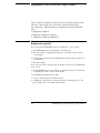
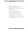
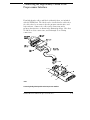
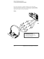
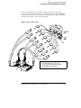
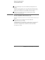
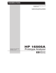
The figure on the next page shows the items used with the
HP E2480A.
ii
E2480A Motorola CPU32 Preprocessor Interface
Introduction
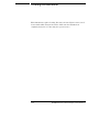
HP E2480A Preprocessor Interface with Microcontroller-specific Attachments and Optional Processor Probe
E2480A Motorola CPU32 Preprocessor Interface
iii
In This Book
This book is the user’s guide for the HP E2480A Preprocessor Interface. It
assumes that you have a working knowledge of the logic analyzer being used
and the microcontroller being analyzed.
This user’s guide is organized into the following chapters:
Overview
• Chapter 1 contains overview information, including a list of required
equipment.
Hooking Up Your System
• Chapter 2 explains how to connect the preprocessor to your target
system, how to connect the preprocessor to a logic analyzer, and how to
configure the preprocessor. It also covers additional equipment
supported by the HP E2480A.
Analyzing the Target System
• Chapter 3 provides information on the format specification and symbols
configured by the preprocessor interface software.
Reference
• Chapter 4 contains reference information on the preprocessor interface
hardware.
If you have a problem
• Chapter 5 contains troubleshooting information.
iv
E2480A Motorola CPU32 Preprocessor Interface
Contents
The HP E2480A Preprocessor Interface —At a Glance ii
1 Overview
Logic Analyzers Supported 1–3
Equipment Used with the Preprocessor 1–4
Equipment supplied 1–4
Minimum equipment required 1–5
Additional equipment supported 1–6
Typical setups using the preprocessor and processor probe
together 1–7
Power-ON/Power-OFF Sequence 1–9
For a stand-alone logic analyzer system 1–9
For a prototype analyzer system 1–9
Connection Sequence 1–10
2 Hooking up Your System
Connecting the Preprocessor to the Target System 2–3
To connect the transition board to the preprocessor 2–4
To connect the preprocessor interface to the probe adapter 2–5
Connecting the probe adapter to the target system 2–6
132-pin PQFP Probe Adapter Rotations 2–7
144-pin TQFP Probe Adapter Rotations 2–8
160-pin QFP Probe Adapter Rotations 2–9
Connecting the Preprocessor to the Logic Analyzer 2–10
Connecting the High-density Cables to the Preprocessor
Interface 2–11
E2480A Motorola CPU32 Preprocessor Interface
Contents-1
Contents
Connecting the High-Density Cables to the Logic Analyzer 2–12
To connect to the HP 1660A/AS/C/CS logic analyzers 2–13
State 2–13
Timing 2–14
To connect to the HP 1661A/AS/C/CS logic analyzers 2–15
State 2–15
Timing 2–16
To connect to the HP 1662A/AS/C/CS logic analyzers 2–17
State 2–17
Timing 2–18
To connect to the HP 1670A/D logic analyzer 2–19
State 2–19
Timing 2–20
To connect to the HP 1671A/D logic analyzer 2–21
State 2–21
Timing 2–22
To connect to the HP 1672A/D logic analyzer 2–23
State 2–23
Timing 2–24
To connect to the HP 16550A logic analyzer 2–25
State 2–25
Timing (one card) 2–26
Timing (two card) 2–27
To connect to the HP 16554/55/56 logic analyzers 2–28
State 2–28
Timing (One or Two Card) 2–29
Configuring the Preprocessor and Logic Analyzer 2–30
Configuring the preprocessor interface 2–31
To set the ID switches 2–31
To interpret the LEDs 2–32
Downloading a configuration 2–34
Configuring With a Debugger 2–34
Configuring With the HP 16505A Prototype Analyzer 2–34
Contents-2
E2480A Motorola CPU32 Preprocessor Interface
Contents
Configuring the Logic Analyzer 2–36
To load the configuration and inverse assembler 2–36
Connecting Optional Equipment 2–38
To connect the HP E3458A Processor Probe 2–39
To connect the HP 16505A Prototype Analyzer 2–39
3 Analyzing the Target System
Modes of Operation 3–3
State mode 3–3
Timing mode 3–3
Format Menu 3–4
Status bit definition and encodings 3–6
Using the Inverse Assembler 3–8
To display captured state data 3–8
To synchronize the inverse assembler 3–9
General output format 3–10
Inverse assembler error messages 3–12
Clock qualifiers 3–12
4 Reference
Operating Characteristics 4–3
Theory of Operation and Clocking 4–4
Timing 4–4
State 4–4
Address reconstruction overview 4–5
Signal-to-connector mapping (Timing) 4–7
State connector signal definition 4–15
Repair Strategy 4–19
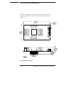
Circuit Board Dimensions 4–20
E2480A Motorola CPU32 Preprocessor Interface
Contents-3
Contents
5 If You Have a Problem
Analyzer Problems 5–3
Intermittent data errors 5–3
Unwanted triggers 5–3
No activity on activity indicators 5–4
No trace list display 5–4
Analyzer won’t power up 5-4
Preprocessor Problems 5–5
Target system will not boot up 5–5
Erratic trace measurements 5–6
Capacitive loading 5–6
Inverse Assembler Problems 5–7
No inverse assembly or incorrect inverse assembly 5–7
Inverse assembler will not load or run 5–8
Intermodule Measurement Problems 5–9
An event wasn’t captured by one of the modules 5–9
Messages 5–10
“. . . Inverse Assembler Not Found” 5–10
“Measurement Initialization Error” 5–11
“No Configuration File Loaded” 5–12
“Selected File is Incompatible” 5–12
“Slow or Missing Clock” 5–12
“Time from Arm Greater Than 41.93 ms” 5–13
“Waiting for Trigger” 5–13
Cleaning the Instrument 5–14
Contents-4
E2480A Motorola CPU32 Preprocessor Interface
1
Overview
Overview
This chapter describes:
•
•
•
•
•
Logic analyzers supported
Equipment used with the preprocessor
Typical setups using the preprocessor and processor probe together
Power-on/power-off sequence
Connection sequence
1-2
E2480A Motorola CPU32 Preprocessor Interface
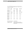
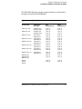
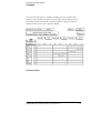
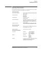
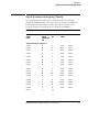
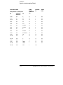
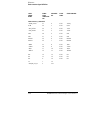
Logic Analyzers Supported
For the HP 16500B mainframe, software revision 3.04 or higher is
recommended. For the HP 16500C mainframe, software revision 1.0
or higher is recommended.
Logic Analyzer
Channel
Count
State Speed
Timing
Speed
Memory Depth
1660A/AS/C/CS
136
100 MHz
250 MHz
4 k states
1661A/AS/C/CS
102
100 MHz
250 MHz
4 k states
1662A/AS/C/CS
68
100 MHz
250 MHz
4 k states
1670A/71A/72A
136/102/68
70 MHz
125 MHz
64 k or .5 M states
1670D/71D/72D
136/102/68
100 MHz
250 MHz
64 k or 1 M states
16550A (one or
two cards)
102/card
100 MHz
250 MHz
4 k states
16554A (one or
two cards)
68/card
70 MHz
125 MHz
512 k states
16555A (one or
two cards)
68/card
110 MHz
250 MHz
1 M states
16555D (one or
two cards)
68/card
110 MHz
250 MHz
2 M states
16556A (one or
two cards)
68/card
100 MHz
200 MHz
1 M states
16556D (one or
two cards)
68/card
100 MHz
200 MHz
2 M states
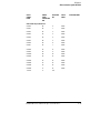
Additional Equipment Supported
Requirements/Features
HP 16505A Prototype Analyzer
Software Version Required: A.01.22 or higher
HP E3458A Processor Probe
Provides Run Control connection to the target system.
Refer the HP E3458A Processor Probe User’s Guide for
operating instructions.
E2480A Motorola CPU32 Preprocessor Interface
1-3
Equipment Used with the Preprocessor
This section lists equipment that can be used with this preprocessor
when it is connected to one of the logic analyzers listed on the
preceding page. This information is organized under the following
titles:
• Equipment supplied
• Minimum equipment required
• Additional equipment supported
Equipment supplied
If you ordered the HP E2480A Preprocessor Interface, you received:
• The HP E2480A Preprocessor Interface circuit board.
• The logic analyzer configuration and inverse assembler software on five
3.5-inch disks.
• Configuration software for the HP 16505A Prototype Analyzer software on
a 3.5-inch disk.
• This User’s Guide.
If you ordered a microcontroller-specific preprocessor package (HP E81xxA)
you received:
• The HP E2480A Preprocessor Interface, which includes the circuit board,
configuration software, and the User’s Guide.
• Four HP E5346A high-density cables.
• A microcontroller-specific transition board.
• A QFP probe adapter kit for your specific microcontroller package. The
probe adapter also comes with a User’s Guide.
1-4
E2480A Motorola CPU32 Preprocessor Interface
Chapter 1: Overview
Equipment Used with the Preprocessor
Minimum equipment required
For state and/or timing analysis of a Motorola CPU32 target system, you need
all of the following:
• The HP E2480A Preprocessor Interface, which includes the circuit board,
configuration software, and the User’s Guide.
•
•
•
•
Two HP E5346A high-density cables.
A microcontroller-specific transition board.
A QFP probe adapter kit for your specific microcontroller package.
The probe adapter User’s Guide, for connecting the probe adapter to the
target system.
• One of the supported logic analyzers. For the HP 165xx logic analyzer
modules, an HP 16500B or HP 16500C mainframe is required.
The above is the minimum equipment required to make a measurement. If you
want to configure the preprocessor interface to reconstruct addresses, you
must also have the HP 3458A Processor Probe.
E2480A Motorola CPU32 Preprocessor Interface
1-5
Chapter 1: Overview
Equipment Used with the Preprocessor
Additional equipment supported
An HP E3458A Processor Probe can be connected through the
HP E2480A to the target system. This eliminates the need for
target-system connectors for run control. The processor probe allows
the user to halt execution, download code, read/write memory and
registers, and step through software. Example connections of a
processor probe are shown in the typical setups on the next pages.
The procedure for connecting a processor probe is given at the end of
Chapter 2.
The E3458A Processor Probe is provided with a graphical user
interface running on the HP 16505A Prototype Analyzer. You can
control target system operation directly from the HP 16505A.
Registers and memory can be displayed and modified. Target code
can be displayed in assembly language.
The E3458A graphical user interface is used to configure the E2480A
preprocessor interface for address reconstruction. Configure the
preprocessor as follows:
1 If the target system contains initialization code, run the target system
until initialization of the SIM registers is complete. The target
processor can be stopped by using a software breakpoint or with the
"break" button.
2 Press the "Read Configuration" button in the processor probe
"Configuration" window."
3 Press the "Load Preprocessor" button in the "Configuration" window.
The preprocessor interface is now ready for address reconstruction.
If your target system does not contain initialization code, manually modify
the SIM register values in the "Configuration" window according to your
target system specification. Then repeat Step 3, above.
1-6
E2480A Motorola CPU32 Preprocessor Interface
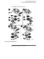
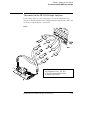
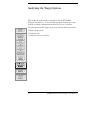
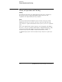
Typical setups using the preprocessor and
processor probe together
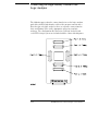
The illustrations in this section show typical equipment setups. The
setup you choose will depend on the type of development or test you
are performing (hardware or software), and the type of logic analyzer
you are using.
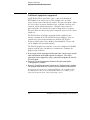
The preprocessor interface supplies signals from the target
microcontroller to the logic analyzer. A configuration file sets up the
logic analyzer to properly interpret these signals.
The preprocessor probe allows you to load program code and run it on
the target system.
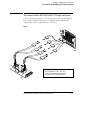
Hardware Designer’s Solution using a Logic Analyzer, Preprocessor, and Processor Probe
E2480A Motorola CPU32 Preprocessor Interface
1-7
Chapter 1: Overview
Typical setups using the preprocessor and processor probe together
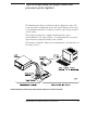
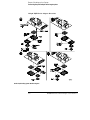
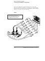
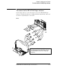
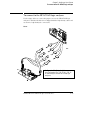
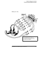
Hardware Designer’s Solution using a Prototype Analyzer, Preprocessor, and Processor Probe
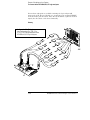
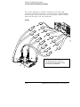
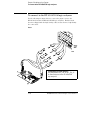
Software Designer’s Solution using a PC or Workstation, Preprocessor, and Processor Probe
1-8
E2480A Motorola CPU32 Preprocessor Interface
Power-ON/Power-OFF Sequence
Listed below are the sequences for powering on and off a
fully-connected preprocessor system. Simply stated, your target
system is always the last to be powered ON.
For powering OFF, the target system is the first to be powered OFF,
then the processor probe (if you have one), then the logic analyzer.
The HP E2480A Preprocessor Interface can be powered from either a logic
analyzer or the software probe. If both devices are attached to the
preprocessor, the logic analyzer supplies the power. If the logic analyzer cables
are removed while the preprocessor is connected to either a powered target or
the software probe, the preprocessor may appear to be powered, but it isn’t. If
this occurs, power off or remove all devices attached to the preprocessor, then
reattach or repower in the proper sequence so that the preprocessor interface
correctly identifies the power source.
For a stand-alone logic analyzer system
With all components connected, power on your system in the
following order:
1. Logic analyzer.
2. Processor probe (if you have one).
3. Target system.
For a prototype analyzer system
1. Turn on the prototype analyzer system. The Measurement Setup Assistant
will guide you through the process of connecting and configuring.
2. When the system is configured, turn on your processor probe (if you have
one), and finally turn on your target system.
E2480A Motorola CPU32 Preprocessor Interface
1-9
Connection Sequence
This manual supports connecting the preprocessor to a stand-alone
logic analyzer or to a prototype analyzer system.
Disconnect power from the logic analyzer and your target system
before you make or break connections. If you have a processor probe,
also disconnect its power.
The connection flow is as follows:
1.
2.
3.
4.
5.
6.
7.
Set switches, if necessary, on the preprocessor board.
Connect the transition board to the preprocessor interface.
Connect preprocessor/transition board to the probe adapter.
Connect the probe adapter to the target system.
Connect the logic analyzer cables to the preprocessor interface.
If you have a processor probe, connect it to the preprocessor.
If you have a processor probe, connect it to your controller (prototype
analyzer, workstation, PC).
8. Load configuration and inverse assembler files into the logic analyzer.
9. If you have a prototype analyzer, load the prototype analyzer configuration
files into the prototype analyzer.
1-10
E2480A Motorola CPU32 Preprocessor Interface
2
Hooking up Your System
Hooking up your System
This chapter shows you how to connect your logic analyzer to your
target system through the preprocessor interface. It also shows how
to connect additional equipment to obtain special features, if desired.
This chapter is divided into the following sections:
•
•
•
•
Connecting the preprocessor to the target system.
Connecting the preprocessor to the logic analyzer.
Configuring the system.
Connecting additional equipment.
2–2
E2480A Motorola CPU32 Preprocessor Interface
Connecting the Preprocessor to the Target
System
This chapter explains how to connect the HP E2480A Preprocessor
Interface to the target system. Connecting to the target system
consists of the following steps:
• Connecting the probe adapter to the target system.
Note that there are separate instructions for the different QFP packages. The
instructions in this manual are only an overview. Use the Users Guide included
with your probe adapter for detailed connecting procedures.
• Connecting the transition board to the preprocessor interface.
• Connecting the preprocessor interface/transition board to the
probe adapter on the target system.
The remainder of this section describes these general steps in more
detail.
The preprocessor interface socket assembly pins are covered for shipment with
a conductive foam wafer or conductive plastic pin protector. This is done to
protect the delicate gold-plated pins from damage due to impact. When you’re
not using the preprocessor interface, protect the socket assembly pins from
damage by covering them with the pin protector.
E2480A Motorola CPU32 Preprocessor Interface
2–3
Chapter 2: Hooking up Your System
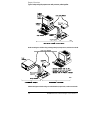
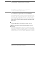
To connect the transition board to the preprocessor
To connect the transition board to the preprocessor
The microcontroller-specific transition board properly routes the signals from
the probe adapter to the preprocessor interface. To connect the transition
board to the preprocessor:
• Verify that there are no bent pins on the PGA socket of the preprocessor.
• Align the beveled corner of the transition board with the pin A1 corner of
the PGA connector on the underside of the preprocessor. The illustration
below shows the beveled corner and the pin A1 corner, as seen from the
top of the preprocessor interface.
CAUTION
Serious damage to the target system or preprocessor interface can result
from incorrect connection. Note the position of pin 1 (or pin A1) on the
target system, transition board, and the preprocessor interface prior to
making any connection. Also, take care to align the preprocessor interface
connector with the pins on the probe adapter assembly so that all pins are
making contact.
• Once all pins are aligned correctly, firmly press the transition board onto
the preprocessor PGA socket. You might need a solid surface to press
against.
Pin A1 Corner and Transition Board Alignment
2–4
E2480A Motorola CPU32 Preprocessor Interface
Chapter 2: Hooking up Your System
To connect the preprocessor interface to the probe adapter
To connect the preprocessor interface to the probe
adapter
The orientation of the preprocessor interface with respect to the probe
adapter depends on the orientation of the probe adapter with respect to pin 1
of the target system. Use the appropriate illustration from the following
pages to ensure you have the proper orientation. To connect the
preprocessor interface to the probe adapter:
• Verify that there are no bent pins on the PGA socket of the transition
board.
• Note the color (or number of black squares) on the side of the probe
adapter or flexible cable that is connected to the pin 1 side of the target
system microcontroller. Orient the preprocessor so that the solid white
side of the transition board aligns with the same color (or number of black
squares) on the PGA end of the probe adapter or flexible cable.
CAUTION
Serious damage to the target system or preprocessor interface can result
from incorrect connection. Note the position of pin 1 (or pin A1) on the
target system, transition board, and the preprocessor interface prior to
making any connection. Also, take care to align the preprocessor interface
connector with the pins on the probe adapter assembly so that all pins are
making contact.
• Once all pins are aligned correctly, firmly press the preprocessor
interface/transition board onto the PGA socket of the probe adapter or
flexible cable.
E2480A Motorola CPU32 Preprocessor Interface
2–5
Chapter 2: Hooking up Your System
Connecting the probe adapter to the target system
Connecting the probe adapter to the target system
The CPU microcontrollers supported by the HP E2480A Preprocessor
Interface come in a variety of QFP packages. The QFP probe adapter
assemblies allow the preprocessor interface to be connected to the target
system without removing the microcontroller from the target system. Refer
to the Probe Adapter Users Guide (included with your HP E81xxA order) for
information on attaching the QFP Probe Adapter to your target system.
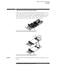
The illustrations on the following pages show the allowable rotations for the
different QFP probe adapters when used with the HP E2480A. Note that the
orientation (rotation) of the preprocessor with respect to the probe adapter
depends on the orientation (rotation) of the probe adapter with respect to
the target system. To ensure that you do not have mechanical interference
between the preprocessor interface and the target system, use the rotation
diagrams on the following pages, and the instructions in "To connect the
preprocessor interface to the probe adapter," to determine the desired
orientation before you connect the probe adapter to the target system.
CAUTION
CAUTION
Serious damage to the target system or preprocessor interface can result
from incorrect connection. Note the position of pin 1 (or pin A1) on the
target system, transition board, and the preprocessor interface prior to
making any connection. Also, take care to align the preprocessor interface
connector with the pins on the probe adapter assembly so that all pins are
making contact.
To prevent equipment damage, remove power from all system components
before making attachments.
2–6
E2480A Motorola CPU32 Preprocessor Interface
Chapter 2: Hooking up Your System
Connecting the probe adapter to the target system
132-pin PQFP Probe Adapter Rotations
132-Pin PQFP Probe Adapter Rotation Diagram
E2480A Motorola CPU32 Preprocessor Interface
2–7
Chapter 2: Hooking up Your System
Connecting the probe adapter to the target system
144-pin TQFP Probe Adapter Rotations
144-Pin TQFP Probing System Rotation Diagram
2–8
E2480A Motorola CPU32 Preprocessor Interface
Chapter 2: Hooking up Your System
Connecting the probe adapter to the target system
160-pin QFP Probe Adapter Rotations
160-Pin QFP Probing System Rotation Diagram
E2480A Motorola CPU32 Preprocessor Interface
2–9
Connecting the Preprocessor to the Logic
Analyzer
This section shows you how to connect the preprocessor to the logic
analyzer. It consists of the following:
• Connecting the high-density cables to the preprocessor interface
• Connecting the high-density cables to the logic analyzer
This section shows connection diagrams that identify connections to
each individual logic analyzer supported by the preprocessor
interface. They are shown in the following order:
•
•
•
•
•
•
•
•
•
•
HP 1660A/AS/C/CS logic analyzers
HP 1661A/AS/C/CS logic analyzers
HP 1662A/AS/C/CS logic analyzers
HP 1670A/D logic analyzers
HP 1671A/D logic analyzers
HP 1672A/D logic analyzers
One-card HP 16550A analyzer
Two-card HP 16550A analyzer
HP 16554A/55A/56A (one-card)
HP 16554A/55A/56A (two-card)
Number of Pods Used/Required
The type of measurement to be made determines the number of logic
analyzer pods to be used. State measurements require four pods.
Full timing measurements require eight pods. If fewer than eight pods
are available for timing, the logic analyzer will truncate the pods
allocated. In this case, viewing the logic analyzer FORMAT menu
shows the pod allocations. If the allocations will not acquire the
desired signals, the allocations can be altered manually.
2–10
E2480A Motorola CPU32 Preprocessor Interface
Connecting the High-density Cables to the
Preprocessor Interface
Four high-density cables, and labels to identify them, are included
with the HP E81xxA. The labels can be attached to the cables after
the cables have been connected to the preprocessor interface and
logic analyzer. Connect the cables to the connectors on the
preprocessor interface as shown in the illustration below. Note that
J1 and J6 are State connectors, and J2 through J5 are Timing
connectors.
Connecting the High-density Cables to the Preprocessor Interface
E2480A Motorola CPU32 Preprocessor Interface
2–11
Connecting the High-Density Cables to the
Logic Analyzer
The following pages show the connections between the logic analyzer
pod cables and the high-density cables of the preprocessor interface.
Note that for each logic analyzer, there are separate connections for
State and Timing. Refer to the appropriate pages for your logic
analyzer. The configuration file names for each logic analyzer and
each CPU32 target system are included with the connection diagrams.
2–12
E2480A Motorola CPU32 Preprocessor Interface
Chapter 2: Hooking up Your System
To connect to the HP 1660A/AS/C/CS logic analyzers
To connect to the HP 1660A/AS/C/CS logic analyzers
Use the following two figures to connect the preprocessor to the HP 1660A/C
logic analyzers. Find the labels that were shipped with the high-density
cables and use them to help identify the connections.
State
Configuration File (State Analysis)
Use configuration files C_33X_1S or
C_37X_1S for state analysis with the
HP 1660A/AS/C/CS logic analyzers.
E2480A Motorola CPU32 Preprocessor Interface
2–13
Chapter 2: Hooking up Your System
To connect to the HP 1660A/AS/C/CS logic analyzers
If fewer than eight pods are available for timing, the logic analyzer will
truncate the pods allocated. In this case, viewing the logic analyzer FORMAT
menu shows the pod allocations. If the allocations will not acquire the desired
signals, the allocations can be altered manually.
Timing
Configuration File (Timing)
Use configuration file C_33X_1T or
C_37X_1T for Timing analysis with the
HP 1660A/AS/C/CS logic analyzers.
2–14
E2480A Motorola CPU32 Preprocessor Interface
Chapter 2: Hooking up Your System
To connect to the HP 1661A/AS/C/CS logic analyzers
To connect to the HP 1661A/AS/C/CS logic analyzers
Use the following two figures to connect the preprocessor to the HP 1661A/C
logic analyzers. Find the labels that were shipped with the high-density
cables and use them to help identify the connections.
State
Configuration File (State Analysis)
Use configuration files C_33X_1S or
C_37X_1S for state analysis with the
HP 1661A/AS/C/CS logic analyzers.
E2480A Motorola CPU32 Preprocessor Interface
2–15
Chapter 2: Hooking up Your System
To connect to the HP 1661A/AS/C/CS logic analyzers
If fewer than eight pods are available for timing, the logic analyzer will
truncate the pods allocated. In this case, viewing the logic analyzer FORMAT
menu shows the pod allocations. If the allocations will not acquire the desired
signals, the allocations can be altered manually.
Timing
Configuration File (Timing)
Use configuration file C_33X_1T or
C_37X_1T for Timing analysis with the
HP 1661A/AS/C/CS logic analyzers.
2–16
E2480A Motorola CPU32 Preprocessor Interface
Chapter 2: Hooking up Your System
To connect to the HP 1662A/AS/C/CS logic analyzers
To connect to the HP 1662A/AS/C/CS logic analyzers
Use the following two figures to connect the preprocessor to the HP 1662A/C
logic analyzers. Find the labels that were shipped with the high-density
cables and use them to help identify the connections.
State
Configuration File (State Analysis)
Use configuration files C_33X_1S or
C_37X_1S for state analysis with the
HP 1662A/AS/C/CS logic analyzers.
E2480A Motorola CPU32 Preprocessor Interface
2–17
Chapter 2: Hooking up Your System
To connect to the HP 1662A/AS/C/CS logic analyzers
If fewer than eight pods are available for timing, the logic analyzer will
truncate the pods allocated. In this case, viewing the logic analyzer FORMAT
menu shows the pod allocations. If the allocations will not acquire the desired
signals, the allocations can be altered manually.
Timing
Configuration File (Timing)
Use configuration file C_33X_1T or
C_37X_1T for Timing analysis with the
HP 1662A/AS/C/CS logic analyzers.
2–18
E2480A Motorola CPU32 Preprocessor Interface
Chapter 2: Hooking up Your System
To connect to the HP 1670A/D logic analyzer
To connect to the HP 1670A/D logic analyzer
Use the figure below to connect the preprocessor to the HP 1670A/D logic
analyzers. Find the labels that were shipped with the high-density cables and
use them to help identify the connections.
State
Configuration File (State Analysis)
Use configuration file C_33X_2S or C_37X_2S
for State analysis with the HP 1670A/D logic
analyzers.
E2480A Motorola CPU32 Preprocessor Interface
2–19
Chapter 2: Hooking up Your System
To connect to the HP 1670A/D logic analyzer
If fewer than eight pods are available for timing, the logic analyzer will
truncate the pods allocated. In this case, viewing the logic analyzer FORMAT
menu shows the pod allocations. If the allocations will not acquire the desired
signals, the allocations can be altered manually.
Timing
Configuration File (Timing)
Use configuration file C_33X_2T or
C_37X_2T for Timing analysis with the
HP 1670A/D logic analyzers.
2–20
E2480A Motorola CPU32 Preprocessor Interface
Chapter 2: Hooking up Your System
To connect to the HP 1671A/D logic analyzer
To connect to the HP 1671A/D logic analyzer
Use the figure below to connect the preprocessor to the HP 1671A/D logic
analyzers. Find the labels that were shipped with the high-density cables and
use them to help identify the connections.
State
Configuration File (State Analysis)
Use configuration file C_33X_2S or C_37X_2S
for State analysis with the HP 1671A/D logic
analyzers.
E2480A Motorola CPU32 Preprocessor Interface
2–21
Chapter 2: Hooking up Your System
To connect to the HP 1671A/D logic analyzer
If fewer than eight pods are available for timing, the logic analyzer will
truncate the pods allocated. In this case, viewing the logic analyzer FORMAT
menu shows the pod allocations. If the allocations will not acquire the desired
signals, the allocations can be altered manually.
Timing
Configuration File (Timing)
Use configuration file C_33X_2T or
C_37X_2T for Timing analysis with the
HP 1671A/D logic analyzers.
2–22
E2480A Motorola CPU32 Preprocessor Interface
Chapter 2: Hooking up Your System
To connect to the HP 1672A/D logic analyzer
To connect to the HP 1672A/D logic analyzer
Use the figure below to connect the preprocessor to the HP 1672A/D logic
analyzers. Find the labels that were shipped with the high-density cables and
use them to help identify the connections.
State
Configuration File (State Analysis)
Use configuration file C_33X_2S or C_37X_2S
for State analysis with the HP 1672A/D logic
analyzers.
E2480A Motorola CPU32 Preprocessor Interface
2–23
Chapter 2: Hooking up Your System
To connect to the HP 1672A/D logic analyzer
If fewer than eight pods are available for timing, the logic analyzer will
truncate the pods allocated. In this case, viewing the logic analyzer FORMAT
menu shows the pod allocations. If the allocations will not acquire the desired
signals, the allocations can be altered manually.
Timing
Configuration File (Timing)
Use configuration file C_33X_2T or
C_37X_2T for Timing analysis with the
HP 1672A/D logic analyzers.
2–24
E2480A Motorola CPU32 Preprocessor Interface
Chapter 2: Hooking up Your System
To connect to the HP 16550A logic analyzer
To connect to the HP 16550A logic analyzer
Use the figure below to connect the preprocessor to the HP 16550A logic
analyzers. Find the labels that were shipped with the high-density cables and
use them to help identify the connections.
State
Configuration File (State Analysis)
Use configuration files C_33X_1S or
C_37X_1S for state analysis with the
HP 16550A logic analyzer.
E2480A Motorola CPU32 Preprocessor Interface
2–25
Chapter 2: Hooking up Your System
To connect to the HP 16550A logic analyzer
If fewer than eight pods are available for timing, the logic analyzer will
truncate the pods allocated. In this case, viewing the logic analyzer FORMAT
menu shows the pod allocations. If the allocations will not acquire the desired
signals, the allocations can be altered manually.
Timing (one card)
Configuration File (Timing)
Use configuration file C_33X_1T or
C_37X_1T for Timing analysis with the
HP 16550A logic analyzer.
2–26
E2480A Motorola CPU32 Preprocessor Interface
Chapter 2: Hooking up Your System
To connect to the HP 16550A logic analyzer
Timing (two card)
Configuration File (Timing)
Use configuration file C_33X_1T or
C_37X_1T for Timing analysis with the
HP 16550A logic analyzer.
E2480A Motorola CPU32 Preprocessor Interface
2–27
Chapter 2: Hooking up Your System
To connect to the HP 16554/55/56 logic analyzers
To connect to the HP 16554/55/56 logic analyzers
Use the following two figure below to connect the preprocessor to the
HP 16554A/55A/56A and HP 16555D/56D logic analyzers. Find the labels
that were shipped with the high-density cables and use them to help identify
the connections.
State
Configuration File (State Analysis)
Use configuration file C_33X_2S or C_37X_2S
for State analysis with the HP 16554/55/56
logic analyzers.
2–28
E2480A Motorola CPU32 Preprocessor Interface
Chapter 2: Hooking up Your System
To connect to the HP 16554/55/56 logic analyzers
If fewer than eight pods are available for timing, the logic analyzer will
truncate the pods allocated. In this case, viewing the logic analyzer FORMAT
menu shows the pod allocations. If the allocations will not acquire the desired
signals, the allocations can be altered manually.
Timing (One or Two Card)
Configuration File (Timing)
Use configuration file C_33X_2T or
C_37X_2T for Timing analysis with the
HP 16554/55/56 logic analyzers.
E2480A Motorola CPU32 Preprocessor Interface
2–29
Configuring the Preprocessor and Logic
Analyzer
This section shows you how to configure the preprocessor and logic
analyzer. It consists of the following steps:
• Configuring the preprocessor interface
• Configuring the logic analyzer
The functionality of the preprocessor and logic analyzer, and the
accuracy of displays provided by the inverse assembler, depend on the
address-reconstruction feature of the preprocessor. For a description
of address reconstruction and its relationship to logic analyzer
functionality, refer to "Address-Reconstruction Overview" in Chapter
4, Reference. This will give you a better understanding of
reconstruction functionality of the preprocessor.
2–30
E2480A Motorola CPU32 Preprocessor Interface
Configuring the preprocessor interface
Configuring the preprocessor interface consists of the following:
• Setting the ID switches
• Interpreting the LEDs
• Downloading a configuration
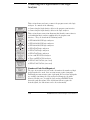
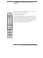
To set the ID switches
The HP E2480A provides an identification (ID) which may be used by other
system components. The ID consists of primary and secondary values. The
primary value is fixed (identifies CPU32 family) by hardware. The secondary
ID is set by the 8-bit switch on the preprocessor, which must be configured to
match the microcontroller being used. Positions 1 - 7 of the switch generate a
binary value which must correspond to the last two digits of the
microcontroller (binary 32 for MC68332). Position 8 is reserved and should
be set to the "1" position.
The figure below shows the switch settings for the MC68332.
Switch Settings for MC68332 Target System
E2480A Motorola CPU32 Preprocessor Interface
2–31
Chapter 2: Hooking up Your System
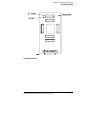
To interpret the LEDs
To interpret the LEDs
The LEDs on the preprocessor interface hardware have meanings described
below, after the following has been done:
1. The ID switches have been set (described in previous section).
2. The preprocessor configuration has been downloaded.
LED Interpretations
• LED DS1 - Default
This LED identifies the type of configuration loaded into the
reconstruction hardware. If the LED is lit, the default configuration is
loaded. If this LED is not lit, a custom configuration is loaded. This
LED only has meaning if LED DS2 is not lit.
• LED DS2 - NO CONFIG
This LED indicates whether or not a configuration has been loaded
into the preprocessor interface. If it is lit, no configuration has been
loaded. If it is not lit, a configuration has been loaded.
• LED DS3 - Reserved for future support of hardware breakpoints.
The illustration on the following page shows the HP E2480A LEDs.
If DS2 remains lit after power has been applied to the preprocessor, the
preprocessor contains an unknown reconstruction configuration. To resolve
this unknown state, cycle power to the preprocessor or execute a "pp load"
command (see next section).
2–32
E2480A Motorola CPU32 Preprocessor Interface
Chapter 2: Hooking up Your System
To interpret the LEDs
HP E2480A LED Locations
E2480A Motorola CPU32 Preprocessor Interface
2–33
Chapter 2: Hooking up Your System
Downloading a configuration
Downloading a configuration
The HP E2480A is shipped with all reconstruction disabled. This
preprocessor configuration provides accurate analysis when A[19:23],
FC[0:2], SIZ0, SIZ1, DSACK0, and DSAK1 are valid. If your target system is
configured differently, you must configure the preprocessor to match your
target system configuration.
To configure the preprocessor, the HP E2480A must be connected to an
HP E3458A Processor Probe. The processor probe must be connected to a
computer via LAN or RS-232-C. The HP E2480A preprocessor may be
configured from either an HP approved debugger or the HP 16505A
Prototype Analyzer. For a list of HP approved debugger vendors, contact
your HP Sales and Service office.
Configuring With a Debugger
Using a debugger, there are two methods of configuration. The first method
requires values to be manually written into SIM/SCIM registers MCR, PEPAR,
CSPAR0, CSPAR1, and the CSBARx and CSORx of all chip selects being
used. The second method requires code to be loaded into the target,
performing a "reset" and "run", then performing a "break" after the SIM/SCIM
registers have been configured. In either case, once the SIM/SCIM registers
are configured, telnet to the processor probe (HP E3458A) and perform
"sync sim" and "pp load". This will place information needed by the
preprocessor for configuration in the preprocessor non-volatile memory.
Configuring With the HP 16505A Prototype Analyzer
Using the HP 16505A Prototype Analyzer, move the uP run control icon into
the workspace, click the right mouse button and select "Start Session"’. A "uP
run control" window should appear. In the "Processor Probe LAN Name"
field, place the LAN name of the HP E3458A connected to the target of
interest and click "start session".
When a connection is established, an "Information" window should appear
indicating connection success. Click on "OK". Another window, "run control"
should also appear. Under the "Window" pull-down menu, select
"Configuration". Two windows should appear, "Configuration" and
"Error/status log".
Using the "Configuration" window, there are two methods of preprocessor
configuration. The first method requires values to be manually written into
SIM/SCIM register fields MCR, PEPAR, CSPAR0, CSPAR1, and the CSBARx
2–34
E2480A Motorola CPU32 Preprocessor Interface
Chapter 2: Hooking up Your System
Downloading a configuration
and CSORxof all chip selects being used. The second method requires code
to be loaded into the target, performing a "reset" and "run", then performing a
"break" after the SIM/SCIM registers have been configured. In either case,
once the "Configuration"’ window SIM/SCIM register fields contain the
desired values, click on the "Load Preprocessor" button. This will place
information needed by the preprocessor for configuration in the preprocessor
non-volatile memory.
E2480A Motorola CPU32 Preprocessor Interface
2–35
Configuring the Logic Analyzer
Configuring the logic analyzer consists of loading the software by
inserting the floppy disk into the logic analyzer disk drive and loading
the proper configuration file. The configuration file you use is
determined by the logic analyzer you are using, and whether you are
performing state analysis or timing analysis.
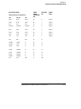
To load the configuration and inverse assembler
The first time you set up the preprocessor interface, make a duplicate copy of
the master disk. For information on duplicating disks, refer to the reference
manual for your logic analyzer.
For logic analyzers with a hard disk, you might want to create a directory
such as MC68332 on the hard drive and copy the contents of the floppy onto
the hard drive. You can then use the hard drive for loading files.
1
2
3
4
Insert the floppy disk in the front disk drive of the logic analyzer.
Go to the Flexible Disk menu.
Configure the menu to load.
Use the knob to select the appropriate configuration file.
Choosing the correct configuration file depends on which analyzer you are
using. The configuration files are shown with the logic analyzer connection
tables, and are also in the table on the next page.
5 Select the appropriate analyzer on the menu. The HP 165xx logic
analyzer modules are shown in the table on the next page.
6 Execute the load operation on the menu to load the file into the logic
analyzer.
The logic analyzer is configured for CPU32 analysis by loading the
appropriate configuration file. Loading a state configuration file also
automatically loads the inverse assembler.
7 If you are using the HP 16505A Prototype Analyzer, insert the "16505
Prototype Analyzer" flexible disk into disk drive of the prototype
analyzer and update the HP 16505A from the Session Manager. You
must close your workspace to run the update.
2–36
E2480A Motorola CPU32 Preprocessor Interface
Chapter 2: Hooking up Your System
To load the configuration and inverse assembler
The HP 16505A Prototype Analyzer requires software version A.01.22
or higher to work with the HP E2480A.
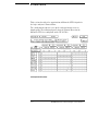
Logic Analyzer Configuration Files
Analyzer Model
16500 Analyzer
Description
State
Configuration File
Timing
Configuration File
16550A (one card)
100 MHz STATE
500 MHz TIMING
C_33X_1S
C_37X_1S
C_33X_1T
C_37X_1T
16550A (two card)
100 MHz STATE
500 MHz TIMING
C_33X_1S
C_37X_1S
C_33X_1T
C_37X_1T
16554A (one card)
0.5M SAMPLE
70/250 MHz LA
C_33X_2S
C_37X_2S
C_33X_2T
C_37X_2T
16555A/D (one card)
1.0M SAMPLE
110/250 MHz LA
C_33X_2S
C_37X_2S
C_33X_2T
C_37X_2T
16556A/D (one card)
1.0M SAMPLE
100/400 MHz LA
C_33X_2S
C_37X_2S
C_33X_2T
C_37X_2T
16554A/D (two card)
0.5M SAMPLE
70/250 MHz LA
C_33X_2S
C_37X_2S
C_33X_2T
C_37X_2T
16555A/D (two card)
1.0M SAMPLE
110/250 MHz LA
C_33X_2S
C_37X_2S
C_33X_2T
C_37X_2T
16556A/D (two card)
1.0M SAMPLE
100/400 MHz LA
C_33X_2S
C_37X_2S
C_33X_2T
C_37X_2T
1660A/AS/C/CS,
1661A/AS/C/CS,
1662A/AS/C/CS
C_33X_1S
C_37X_1S
C_33X_1T
C_37X_1T
1670A/D,
1671A/D,
1672A/D
C_33X_2S
C_37X_2S
C_33X_2T
C_37X_2T
E2480A Motorola CPU32 Preprocessor Interface
2–37
Chapter 2: Hooking up Your System
To load the configuration and inverse assembler
Connecting Optional Equipment
The remaining portion of this chapter shows you how to connect
optional equipment you may wish to use to obtain additional
functionality. At the time this manual was printed, the following
optional equipment was available for use with the preprocessor
interface:
• HP E3458A Processor Probe
• HP 16505A Prototype Analyzer
2–38
E2480A Motorola CPU32 Preprocessor Interface
Chapter 2: Hooking up Your System
To connect the HP E3458A Processor Probe
To connect the HP E3458A Processor Probe
The processor probe allows you to halt execution, download code (if the
target is RAM based), read/write memory and registers, and step through
software. The HP E3458A also provides a connector to source-level
debuggers, which are available from a number of vendors. Refer to the
HP E3458A Data Sheet for a list of supported debuggers.
To connect the processor probe to the preprocessor interface, use the
following procedure.
1 Turn off power. Refer to Power-On/Power-Off Sequence in Chapter 1.
2 Connect the 50-pin cable to the processor probe. Then connect the
other end of the cable to the 50-pin connector on the preprocessor
interface. The connectors are keyed.
3 Turn on power. Refer to Power-On/Power-Off Sequence in Chapter 1.
To connect the HP 16505A Prototype Analyzer
Refer to the HP E3458A Processor Probe User’s Guide for instructions on
connecting to the HP 16505A Prototype Analyzer.
E2480A Motorola CPU32 Preprocessor Interface
2–39
2–40
E2480A Motorola CPU32 Preprocessor Interface
3
Analyzing the Target System
Analyzing the Target System
This chapter describes modes of operation for the HP E2480A
Preprocessor Interface. It also describes preprocessor interface data,
symbol encodings, and information about the inverse assembler.
The information in this chapter is presented in the following sections:
• Modes of operation
• Format menu
• Using the inverse assembler
3–2
E2480A Motorola CPU32 Preprocessor Interface
Modes of Operation
The HP E2480A Preprocessor Interface can be used in State mode or
Timing mode. The following sections describe these operating modes.
State mode
In State mode, the logic analyzer uses clock store qualification to capture
address, data, and status information once during an instruction or data
cycle. This mode is set up by the State configuration files. The State
configuration files also automatically load the inverse assembler.
Timing mode
In Timing mode, the logic analyzer samples the microcontroller pins
asynchronously, at a user-selected sampling rate. The Timing mode is set up
by the Timing configuration files.
State and Timing modes use different connectors on the preprocessor
interface. The Timing pins are direct connections to the microcontroller signals.
The State pins have active circuitry on the preprocessor interface. State
information is acquired three target system clock cycles after the same
information is captured in Timing mode.
E2480A Motorola CPU32 Preprocessor Interface
3–3
Format Menu
This section describes the organization of Motorola CPU32 signals in
the logic analyzer’s Format Menu.
The configuration software sets up the analyzer format menu to
display pods. The following figures show the Format Menu for the
Motorola CPU32 as configured on the HP 16550A.
Format Specification (State)
3–4
E2480A Motorola CPU32 Preprocessor Interface
Analyzing the Target System
Timing mode
If fewer than eight pods are available for timing, the logic analyzer will
truncate the pods allocated. In this case, the logic analyzer Format menu
shows the pod allocations. If the allocations will not acquire the desired
signals, the allocations can be altered manually.
Format Menu (Timing)
E2480A Motorola CPU32 Preprocessor Interface
3–5
Analyzing the Target System
Status bit definition and encodings
Status bit definition and encodings
This section describes symbol information that has been set up by the
preprocessor interface configuration software and information about the
available inverse assemblers including filtering and debug monitors.
The table below is specifically for a state configuration. The timing
configurations have many of the same signals, and those signals are
represented by the same symbols used for state configurations.
HP E2480A STAT Bit Description
Bit
0
STAT Label
~ShoCy
1
Rd/~Wr
2
~IFtch
Indicates the bus cycle is an instruction fetch.
3
~PFlsh
Indicates the instruction pipe has been flushed.
4:5
Sizx
6:7
DSAckx
8
~BErr
9
~Freeze
10
~Bkpt
11
~BGAck
12:14
FCx
Indicates the number of bytes being written or
capable of being read.
Indicates the port size (in bytes) of the
peripheral being read from/ written to.
Indicates that the bus cycle terminated with an
error.
When asserted, indicates the microcontroller is
in background mode.
Indicates a hardware breakpoint has been
encountered.
When asserted, indicates the microcontroller
does not own the bus.
These bits indicate the area of memory with
which a transfer is taking place.
3–6
Description
When this bit is asserted, it indicates the
execution of an internal (show) cycle.
Indicates the direction of the transfer.
E2480A Motorola CPU32 Preprocessor Interface
Analyzing the Target System
Status bit definition and encodings
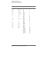
CPU32 Symbolic Representation of Status Bits
Label
~ShoCy
Signal
~Show_Cycle
Rd/~Wr
Rd/~Wr
~IFtch
~Inst_Fetch
~PFlsh
~Pipe_Flush
Sizx
Siz[0:1]
DSAckx
DSAck[0:1]
~BErr
~BErr
~Freez
~Freeze
~Bkpt
~Bkpt
~BGAck
~BGAck
FCx
FC[0:2]
Symbol
Int
Ext
Wr
Rd
Fetch
(blank)
Flush
(blank)
long
byte
word
3byt
(blank)
word
byte
wait
Error
(blank)
Bkgrnd
Runnin
Break
(blank)
NoBus
(blank)
show
user data
user pgrm
(blank)
(blank)
supr data
supr prgm
CPU
E2480A Motorola CPU32 Preprocessor Interface
Value
0
1
0
1
0
1
0
1
00
01
10
11
00
01
10
11
0
1
0
1
0
1
0
1
000
001
010
011
100
101
110
111
3–7
Using the Inverse Assembler
This section discusses the general output format of the inverse
assembler and controller-specific information. This section also
assumes that an inverse assembler has been loaded.
To display captured state data
• Select the Listing Menu for your logic analyzer.
The logic analyzer displays captured state data in the Listing Menu. The
inverse assembler display is obtained by setting the base for the DATA label
to Invasm. The following figure shows a typical Listing Menu.
3–8
E2480A Motorola CPU32 Preprocessor Interface
Analyzing the Target System
To synchronize the inverse assembler
To synchronize the inverse assembler
The CPU32 microcontroller does not indicate externally which word fetched
is the beginning of a new instruction. You may have to "point" to the first
state of an instruction fetch to synchronize the inverse assembler. Once
synchronized, the inverse assembler will disassemble from this state through
the end of the screen. To synchronize the inverse assembler:
• Identify a line on the display that you know is the first state of an
instruction fetch.
• Roll this line to the top of the listing.
• Press the Invasm field at the top of the screen.
This will cause the Invasm Options submenu to appear.
• Press the Align softkey.
The listing will inverse assemble from the top line down. Any data before this
screen is left unchanged. Rolling the screen up will inverse assemble the lines
as they appear on the bottom of the screen. If you jump to another area of
the listing by entering a new line number or by rolling the screen down, you
may have to re-synchronize the inverse assembler by repeating the described
steps.
Each time you inverse assemble a block of memory, the analyzer will keep
that block in the inverse assembled condition. You can inverse assemble
several different blocks in the analyzer memory, but the activity between
those blocks will not be inverse assembled.
E2480A Motorola CPU32 Preprocessor Interface
3–9
Analyzing the Target System
General output format
General output format
The next few paragraphs describe the general output format of the inverse
assemblers.
Numeric Format
Unless a value is followed by a suffix character, numeric output from the
inverse assembler is in hexadecimal format. For example, decimal values
have a period (.) as the suffix character; binary values have a percent sign
(%).
Missing Opcodes/Operands
Asterisks (*) in the inverse assembler output indicate missing operands.
Missing operands occur frequently and are primarily due to microcontroller
prefetch activity. Storage qualification or the use of storage windows can also
lead to such occurrences.
Don’t Care Bytes
The CPU32 microcontroller can perform byte transfers. During operand
reads and writes, entire 16-bit (word) values appear on the microcontroller
data bus lines. The inverse assembler will attempt to display "xx" for any
bytes in a transfer that is invalid. You can then determine exactly which byte
of data was used as an operand. If the microcontroller is configured such that
the number of bytes being transferred cannot be determined, an entire word
will be displayed. You must then determine which bytes are valid.
Unexecuted Prefetched Instructions
Prefetched instructions which are not executed by the microcontroller are
marked by a hyphen "-" in the first column of the mnemonic/hex field
The logic analyzer captures prefetches even if they are not executed. Care
must be taken when specifying a trigger condition or a storage qualification
that follows an instruction that may cause branching. An unused prefetch
may generate an unwanted trigger.
Since the microcontroller only prefetches at most two words, one technique
to avoid unwanted triggering from unused prefetches is to add "4" to the
trigger address. This trigger condition will only be satisfied if the branch is
not taken.
3–10
E2480A Motorola CPU32 Preprocessor Interface
Analyzing the Target System
General output format
Processor-Specific Output Format
The logic analyzer captures all bus cycles. This includes background and
coprocessor cycles as well as code cycles.
A "c" marks coprocessor activity, and background activity is marked with a
"b". The "c" and "b" are displayed in the first column of the mnemonic/hex
field. Acquisitions of coprocessor and background cycles may be individually
enabled/disabled via the trigger menu.
General Missing Terms
Depending on the configuration of the microcontroller, the inverse assembler
may be unable to supply all the of the information it can supply. For example,
if ~DS (data strobe) is not valid, internal cycles cannot be captured.
Filtering
The CPU32 inverse assembler is capable of suppressing certain acquired
cycles from the display, thus allowing the user to focus on and display more
cycles of interest. The filter softkeys are part of the "Invasm Options"
submenu. "Invasm Options" must be pressed to display the submenu.
Cycle suppression is broken down into the following categories: extension
words, unexecuted prefetches, branches, calls and returns, other
instructions, data reads, and data writes.
Extension words and unexecuted fetches are suppressed without regard to
user mode or supervisor mode because they do not affect the display of
executed mnemonics.
All other categories may suppress based on the user mode, supervisor mode,
or both. These categories suppress actual executed mnemonics for the
display.
E2480A Motorola CPU32 Preprocessor Interface
3–11
Analyzing the Target System
Inverse assembler error messages
Inverse assembler error messages
Any of the following list of error messages may appear during analysis of your
target software. Included with each message is a brief explanation.
Fatal Data Error
Displayed if the trace memory could not be read properly on entry into the
inverse assembler.
Illegal Opcode <code>
Displayed if the inverse assembler encounters an illegal instruction.
Reserved Opcode
Displayed if the inverse assembler encounters a reserved coprocessor
instruction.
Incomplete Opcode
Displayed if the inverse assembly cannot acquire all words of a multi-word
instruction.
* (asterisk)
Displayed if the inverse assembler cannot find a complete operand field for
an instruction. Prefetch activity or storage qualification is often the cause.
Clock qualifiers
If you do want to acquire Background cycles, add "L=1" as a clock qualifier. If
you do not want to acquire coprocessor cycles, add "M=1" as a clock qualifier.
3–12
E2480A Motorola CPU32 Preprocessor Interface
4
Reference
Reference
This chapter contains additional reference information including the
signal mapping for the HP E2480A Preprocessor Interface.
The information in this chapter is presented in the following sections:
•
•
•
•
•
•
•
Operating characteristics
Theory of operation and clocking
Address-reconstruction overview
Signal-to-connector mapping (timing)
State connector signal definition
Repair strategy
Circuit board dimensions
4–2
E2480A Motorola CPU32 Preprocessor Interface
Reference
Operating Characteristics
Operating Characteristics
The following operating characteristics are not specifications, but are typical
operating characteristics for the preprocessor interface.
Product Characteristics
Microcontroller Supported
Motorola 68331, 68332, 68F333, 68334, 68335, 68336,
68338, or 68376
Package Supported
132-pin PQFP
144-pin TQFP
160-pin PQFP
Probes Required
Mandatory 4 for state.
Up to 8 for timing.
Accessories Required
See chapter 1 for available accessories. A probe
adapter and a transition board are required. For
address reconstruction, the HP E3458A Processor
Probe is required.
Optional Accessories
The HP E3458A Processor Probe connects to the
preprocessor interface and provides Run Control.
Electrical Characteristics
Power Requirements
650 mA typical @ 5V, supplied by logic analyzer or
the HP E3458A Processor Probe.
Signal Line Loading
10 pF maximum on all signals.
Environmental Characteristics
Temperature
Operating
Nonoperating
Altitude
Operating
Nonoperating
Humidity
0 to + 55 degrees C
+32 to +131 degrees F
-40 to + 75 degrees C
-40 to +167 degrees F
4,600 m
15,000 feet
15,3000 m
50,000 feet
Up to 90% noncondensing. Avoid sudden , extreme
temperature changes which could cause
condensation on the circuit board.
E2480A Motorola CPU32 Preprocessor Interface
4–3
Reference
Theory of Operation and Clocking
Theory of Operation and Clocking
Timing
For timing measurements, raw digital signals from the microcontroller are
presented to the logic analyzer through the timing connectors. The
acquisition clock is provided by the logic analyzer.
State
For state measurements, all signals are processed by active logic for time
alignment before they are routed to the state connectors. This allows the
logic analyzer to capture all information about a given cycle in one acquisition
state.
Some of the signals which assist the preprocessor in triggering and aligning
the source code are reconstructed from their reconfigured functions as chip
selects or general I/O. The preprocessor interface must be configured to
match the target system for this reconstruction function to work.
A qualified target system clock is used by the logic analyzer to acquire state
cycles.
4–4
E2480A Motorola CPU32 Preprocessor Interface
Reference
Address reconstruction overview
Address reconstruction overview
When CPU32 microcontrollers are reconfigured, they can present special
problems for debugging. This is especially true when address bits A[19:23]
are reconfigured as chip selects. The HP E2480A Preprocessor Interface
overcomes these problems by using information in the base address register
associated with such chip selects to replace the missing address bits. The
value injected into the signal path depends on which chip select is active.
Refer to chapter 2 for information on programming the preprocessor
interface.
This reconstruction provides many benefits when analyzing a target system:
• Triggering on address A0 through A23 is possible, even when the upper
address bits are not available from the target microprocessor.
• The software analyzer, with its increased analysis capabilities, can be used.
• Code captured in a trace can be correlated with mnemonics in the source
database.
• Alignment of activity shown in a trace list.
The HP E2480A also reconstructs function control bits FC[0:2] when they are
configured as chip selects, and SIZ[0:1] and DSAck[0:1] when they are
configured as general I/O.
The programming is non-volatile. Once programmed, the HP E2480A does
not need to remain connected to the processor probe to maintain address
reconstruction.
The figure on the following page shows the process by which the HP E2480A
reconstructs addresses.
State and Timing modes use different connectors on the preprocessor
interface. The Timing pins are direct connections to the microcontroller signals.
The State pins have active circuitry on the preprocessor interface. State
information is acquired three target system clock cycles after the same
information is captured in Timing mode.
E2480A Motorola CPU32 Preprocessor Interface
4–5
Reference
Address reconstruction overview
Address Reconstruction Overview
4–6
E2480A Motorola CPU32 Preprocessor Interface
Reference
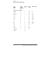
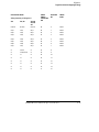
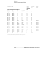
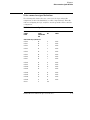
Signal-to-connector mapping (Timing)
Signal-to-connector mapping (Timing)
The following table shows the flow of signals from the microcontroller
through the E2480A timing connectors to the logic analyzer. In addition to
being grouped along microprocessor-like functions, the signals are also
grouped and ordered along their microcontroller port definitions.
CPU32 Signal List
CPU32
SIGNAL
NAME
E2480A
TIMING
CONNECTOR
PIN
ANALYZER
BIT
TIMING
LABEL
TIMING SUBLABEL
Timing Connector J5, Timing Pod 1
DATA0
38
0
DATA
PORT H
DATA1
36
1
DATA
PORT H
DATA2
34
2
DATA
PORT H
DATA3
32
3
DATA
PORT H
DATA4
30
4
DATA
PORT H
DATA5
28
5
DATA
PORT H
DATA6
26
6
DATA
PORT H
DATA7
24
7
DATA
PORT H
DATA8
22
8
DATA
PORT G
DATA9
20
9
DATA
PORT G
DATA10
18
10
DATA
PORT G
DATA11
16
1
DATA
PORT G
DATA12
14
12
DATA
PORT G
DATA13
12
13
DATA
PORT G
DATA14
10
14
DATA
PORT G
DATA15
8
15
DATA
PORT G
ClkOut
6
CLK
E2480A Motorola CPU32 Preprocessor Interface
4–7
Reference
Signal-to-connector mapping (Timing)
CPU32
SIGNAL
NAME
E2480A
TIMING
CONNECTOR
PIN
ANALYZER
BIT
TIMING
LABEL
TIMING SUBLABEL
Timing Connector J5, Timing Pod 2
~BR/CS0
37
0
STAT
CSx
~BG/CS1
35
1
STAT
CSx
~BGAck/CS2
33
2
STAT
CSx
DSAck0
31
3
STAT
PORT E
DSAck1
29
4
STAT
PORT E
~AVec
27
5
STAT
PORT E
~RMC
25
6
STAT
PORT E
~DS
23
7
STAT
PORT E
~AS
21
8
STAT
PORT E
SIZ0
19
9
STAT
PORT E
SIZ1
17
10
STAT
PORT E
R/~W
15
11
STAT
~BERR
13
12
STAT
~HALT
11
13
STAT
~Targ_Reset
9
14
STAT
~Freeze/Quote
7
15
~CSBoot
5
CLK
4–8
E2480A Motorola CPU32 Preprocessor Interface
Reference
Signal-to-connector mapping (Timing)
CPU32
SIGNAL
NAME
E2480A
TIMING
CONNECTOR
PIN
ANALYZER
BIT
TIMING
LABEL
TIMING SUBLABEL
Timing Connector J4, Timing Pod 3
ADDR0
38
0
ADDR
ADDR1
36
1
ADDR
ADDR2
34
2
ADDR
ADDR3
32
3
ADDR
PORT B
ADDR4
30
4
ADDR
PORT B
ADDR5
28
5
ADDR
PORT B
ADDR6
26
6
ADDR
PORT B
ADDR7
24
7
ADDR
PORT B
ADDR8
22
8
ADDR
PORT B
ADDR9
20
9
ADDR
PORT B
ADDR10
18
10
ADDR
PORT B
ADDR11
16
11
ADDR
PORT A
ADDR12
14
12
ADDR
PORT A
ADDR13
12
13
ADDR
PORT A
ADDR14
10
14
ADDR
PORT A
ADDR15
8
15
ADDR
PORT A
E2480A Motorola CPU32 Preprocessor Interface
4–9
Reference
Signal-to-connector mapping (Timing)
CPU32
SIGNAL
NAME
E2480A
TIMING
CONNECTOR
PIN
ANALYZER
BIT
TIMING
LABEL
TIMING SUBLABEL
Timing Connector J4, Timing Pod 4
ADDR16
37
0
ADDR
PORT A
ADDR17
35
1
ADDR
PORT A
ADDR18
33
2
ADDR
PORT A
FC0/CS3
31
3
PORT C
CSx
FC1/CS4
29
4
PORT C
CSx
FC2/CS5
27
5
PORT C
CSx
ADDR19/~CS6
25
6
ADDR
PORT C
CSx
ADDR20/~CS7
23
7
ADDR
PORT C
CSx
ADDR21/~CS8
21
8
ADDR
PORT C
CSx
ADDR22/~CS9
19
9
ADDR
PORT C
CSx
ADDR23/~CS10
17
10
ADDR
PORT C
CSx
na
15
11
na
13
12
na
11
13
~IFetch/DS1
9
14
~IPipe/DS0
7
15
~Bkpt/DSclk
5
CLK
NOTE: Signals A19—A23 and CS6—CS10 are multiplexed onto the same pins, and the default
configuration of the logic analyzer assumes that signals A19—A23 are valid. If any of the chip
selects, CS6—CS10, are being used then the bits associated with A19—A23 should be
removed from the ADDR label via the format menu in the logic analyzer. This corresponds to
bits 3—7 of pod A4. This results in the display of correct address information in the ADDR
field of the listing menu and presents only valid address bus bits to the ADDR field in the
trigger menu.
4–10
E2480A Motorola CPU32 Preprocessor Interface
Reference
Signal-to-connector mapping (Timing)
CPU32 SIGNAL NAME
Timing Connector J2, Timing Pod 5
E2480A
TIMING
CONNECTOR
PIN
ANALYZER
BIT
TIMING
LABEL
338
336, 376
333
MISO
MISO
MISO
38
0
PORT Q
MOSI
MOSI
MOSI
36
1
PORT Q
SCK
SCK
SCK
34
2
PORT Q
PCS0/SS
PCS0/SS
PCS0/SS
32
3
PORT Q
PCS1
PCS1
PCS1
30
4
PORT Q
PCS2
PCS2
PCS2
28
5
PORT Q
PCS3
PCS3
PCS3
26
6
PORT Q
TxD
TxD
TxD
24
7
PORT Q
RxD
RxD
RxD
22
8
CTS24B
CTM2C
nc
20
9
CTS24A
CTD3
nc
18
10
CTD29
CTD4
nc
16
1
CTD28
CPWM5
nc
14
12
CTD27
CPWM6
nc
12
13
CTD26
CPWM7
nc
10
14
CTM31L
CPWM8
nc
8
15
SCK
SCK
SCK
6
CLK
E2480A Motorola CPU32 Preprocessor Interface
4–11
Reference
Signal-to-connector mapping (Timing)
CPU32 SIGNAL NAME
Timing Connector J2, Timing Pod 6
E2480A
TIMING
CONNECTOR
PIN
ANALYZER
BIT
TIMING
LABEL
338
376, 336, 335,
334, 333, 332
331
CTIO0
TP0
nc
37
0
TPU
CTIO1
TP1
IC1
35
1
TPU
CTD10
TP2
IC2
33
2
TPU
CTD9
TP3
IC3
31
3
TPU
CTD8
TP4
OC1
29
4
TPU
CTD7
TP5
OC1/OC2
27
5
TPU
CTD6
TP6
OC1/OC3
25
6
TPU
CTD5
TP7
nc
23
7
TPU
CTD4
TP8
OC1/OC4
21
8
TPU
CTIO2
TP9
OC1/OC5/IC4
19
9
TPU
CTIO3
TP10
PAI
17
10
TPU
CTS14B
TP11
nc
15
11
TPU
CTS14A
TP12
nc
13
12
TPU
CTIO4
TP13
nc
11
13
TPU
CTIO5
TP14
PWMA
9
14
TPU
TPU
CTS18B
TP15
PWMB
7
15
CTS18A
T2clk
PClk
5
CLK
4–12
E2480A Motorola CPU32 Preprocessor Interface
Reference
Signal-to-connector mapping (Timing)
CPU32 SIGNAL NAME
Timing Connector J3, Timing Pod 7
E2480A
TIMING
CONNECTOR
PIN
ANALYZER
BIT
TIMING
LABEL
338
336, 376
335, 334,
333, 332,
331
ModClk
ModClk
ModClk
38
0
PORT F
IRQ1
IRQ1
IRQ1
36
1
PORT F
IRQ2
IRQ2
IRQ2
34
2
PORT F
IRQ3
IRQ3
IRQ3
32
3
PORT F
IRQ4
IRQ4
IRQ4
30
4
PORT F
IRQ5
IRQ5
IRQ5
28
5
PORT F
IRQ6
IRQ6
IRQ6
26
6
PORT F
IRQ7
IRQ7
IRQ7
24
7
PORT F
nc
CDT10
nc
22
8
nc
CTD9/CTM2L
nc
20
9
nc
nc
nc
18
10
nc
nc
nc
16
11
nc
nc
nc
14
12
nc
nc
nc
12
13
nc
nc
nc
10
14
nc
nc
nc
8
15
E2480A Motorola CPU32 Preprocessor Interface
4–13
Reference
Signal-to-connector mapping (Timing)
CPU32 SIGNAL NAME
Timing Connector J3, Timing Pod 8 (338 is nc)
E2480A
TIMING
CONNECTOR
PIN
ANALYZER
BIT
TIMING
LABEL
336, 376
333
334
335, 332, 331
A2D_A0
A2D_B0
nc
nc
37
0
A2D_A1
A2D_B1
nc
nc
35
1
A2D_A2
A2D_B2
nc
nc
33
2
A2D_A3
A2D_B3
nc
nc
31
3
A2D_A4
A2D_B4
nc
nc
29
4
A2D_A5
A2D_B5
nc
nc
27
5
A2D_A6
A2D_B6
nc
nc
25
6
A2D_A7
A2D_B7
VDDA
MISO
23
7
PORT Q*
A2D_B0
A2D_A0
VSSA
MOSI
21
8
PORT Q*
A2D_B1
A2D_A1
A2D_A0
SCK
19
9
PORT Q*
A2D_B2
A2D_A2
A2D_A1
PCS0/SS
17
10
PORT Q*
A2D_B3
A2D_A3
A2D_A2
PCS1
15
11
PORT Q*
A2D_B4
A2D_A4
A2D_A3
PCS2
13
12
PORT Q*
A2D_B5
A2D_A5
A2D_A4
PCS3
11
13
PORT Q*
A2D_B6
A2D_A6
A2D_A5
TxD
9
14
PORT Q*
A2D_B7
A2D_A7
A2D_A6
RxD
7
15
nc
nc
nc
nc
5
CLK
*The PORT Q labels are valid only for the 331, 332, and 335 microprocessors.
4–14
E2480A Motorola CPU32 Preprocessor Interface
Reference
State connector signal definition
State connector signal definition
The following table defines the state connectors, the logic analyzer bit
assignments, and the label/sublabel(s) to which a signal belongs. This table
aids in reconfiguring the logic analyzer to match a particular microcontroller
configuration.
E2480A State Connector Signal List
CPU32
SIGNAL
NAME
E2480A
STATE
CONNECTOR
PIN
ANALYZER
BIT
STATE
LABEL
STATE SUBLABEL
State Connector J1, State Pod 1
DATA0
38
0
DATA
DATA1
36
1
DATA
DATA2
34
2
DATA
DATA3
32
3
DATA
DATA4
30
4
DATA
DATA5
28
5
DATA
DATA6
26
6
DATA
DATA7
24
7
DATA
DATA8
22
8
DATA
DATA9
20
9
DATA
DATA10
18
10
DATA
DATA11
16
1
DATA
DATA12
14
12
DATA
DATA13
12
13
DATA
DATA14
10
14
DATA
DATA15
8
15
DATA
ClkOut
6
CLK
E2480A Motorola CPU32 Preprocessor Interface
4–15
Reference
State connector signal definition
CPU32
SIGNAL
NAME
E2480A
STATE
CONNECTOR
PIN
ANALYZER
BIT
STATE
LABEL
STATE SUBLABEL
State Connector J1, State Pod 2
~SHOW_CYCLE
37
0
STAT
~ShoCy
R/~W
35
1
STAT
R/~W
~INST_FETCH
33
2
STAT
~IFtch
~PIPE_FLUSH
31
3
STAT
~PFlsh
SIZ0
29
4
STAT
SIZx
SIZ1
27
5
STAT
SIZx
DSAck0
25
6
STAT
DSACKx
DSAck1
23
7
STAT
DSACKx
~BERR
21
8
STAT
~BErr
~Freeze
19
9
STAT
~Freez
~Bkpt
17
10
STAT
~Bkpt
~BGAck
15
11
STAT
~BGAck
FC0
13
12
STAT
FCx
FC1
11
13
STAT
FCx
FC2
9
14
STAT
FCx
na
7
15
~Analyzer_clk_en
5
CLK
4–16
E2480A Motorola CPU32 Preprocessor Interface
Reference
State connector signal definition
CPU32
SIGNAL
NAME
E2480A
STATE
CONNECTOR
PIN
ANALYZER
BIT
STATE
LABEL
STATE SUBLABEL
State Connector J6, State Pod 3
ADDR0
38
0
ADDR
ADDR1
36
1
ADDR
ADDR2
34
2
ADDR
ADDR3
32
3
ADDR
ADDR4
30
4
ADDR
ADDR5
28
5
ADDR
ADDR6
26
6
ADDR
ADDR7
24
7
ADDR
ADDR8
22
8
ADDR
ADDR9
20
9
ADDR
ADDR10
18
10
ADDR
ADDR11
16
11
ADDR
ADDR12
14
12
ADDR
ADDR13
12
13
ADDR
ADDR14
10
14
ADDR
ADDR15
8
15
ADDR
~Freeze
6
CLK
E2480A Motorola CPU32 Preprocessor Interface
4–17
Reference
State connector signal definition
CPU32
SIGNAL
NAME
E2480A
STATE
CONNECTOR
PIN
ANALYZER
BIT
STATE
LABEL
0
ADDR
STATE SUBLABEL
State Connector J6, State Pod 4
ADDR16
37
ADDR17
35
1
ADDR
ADDR18
33
2
ADDR
ADDR19
31
3
ADDR
ADDR20
29
4
ADDR
ADDR21
27
5
ADDR
ADDR22
25
6
ADDR
ADDR23
23
7
ADDR
~BGAck
5
CLK
4–18
E2480A Motorola CPU32 Preprocessor Interface
Reference
Repair Strategy
Repair Strategy
The repair strategy for this preprocessor interface is board replacement.
However, the following table lists some mechanical parts that may be
replaced if they are damaged or lost. Contact your nearest Hewlett-Packard
Sales Office for further information on servicing the board.
Exchange assemblies are available when a repairable assembly is returned to
Hewlett-Packard. These assemblies have been set up on the "Exchange
Assembly" program. This allows you to exchange a faulty assembly with one
that has been repaired, calibrated, and performance verified by the factory.
The cost is significantly less than that of a new assembly.
Replaceable Parts
HP Part Number
Description
HP E2480A
E2480-69502
Circuit board assembly
E2480-68701
Inverse assembler disk pouch
5041-9491
Extraction Tool
E5346A
Flexible Adapter Cable
HP E8115A
E3417A
Generic 132-Pin QFP Probe
E8119A
132-pin QFP-FC 6833X Transition Board
HP E8116A
E5336A
144-Pin Elas Probe
E5338A
144-pin TQFP 68332 Adapter
E8120A
144-pin QFP-FV 6833X Transition Board
HP E8118A
E5350A
176-pin TQFP Generic Flex
E5373A
160-pin QFP Elast Probe Adapt
E8122A
160-pin QFP-FT 68336 Transition Board
E2480A Motorola CPU32 Preprocessor Interface
4–19
Circuit Board Dimensions
The following figure gives the dimensions for the preprocessor
interface assembly. The dimensions are listed in inches and
millimeters.
Circuit Board Dimension Diagram
4–20
E2480A Motorola CPU32 Preprocessor Interface
5
If You Have a Problem
If You Have a Problem
Occasionally, a measurement may not give the expected results. If you
encounter difficulties while making measurements, use this chapter to
guide you through some possible solutions. Each heading lists a
problem you may encounter, along with some possible solutions.
The information in this chapter is presented in the following sections:
•
•
•
•
•
•
Analyzer problems
Preprocessor problems
Inverse assembler problems
Intermodule measurement problems
Messages
Cleaning the instrument
If you still have difficulty using the analyzer after trying the
suggestions in this chapter, please contact your local Hewlett-Packard
service center.
CAUTION
When you are working with the analyzer, be sure to power down both the
analyzer and the target system before disconnecting or connecting cables,
probes, and preprocessors. Otherwise, you may damage circuitry in the
analyzer, preprocessor, or target system.
5–2
E2480A Motorola CPU32 Preprocessor Interface
Analyzer Problems
This section lists general problems that you might encounter while
using the analyzer.
Intermittent data errors
This problem is usually caused by poor connections, incorrect signal levels, or
marginal timing.
Remove and reseat all cables and probes, ensuring that there are no
bent pins on the preprocessor interface or poor probe connections.
Adjust the threshold level of the data pod to match the logic levels in the
system under test.
Use an oscilloscope to check the signal integrity of the data lines.
Clock signals for the state analyzer must meet particular pulse shape and
timing requirements. Data inputs for the analyzer must meet pulse shape and
setup and hold time requirements.
See Also
See “Capacitive Loading” in this chapter for information on other sources of
intermittent data errors.
Unwanted triggers
Unwanted triggers can be caused by instructions that were fetched but not
executed.
Add the prefetch queue or pipeline depth to the trigger address to avoid
this problem.
The logic analyzer captures prefetches, even if they are not executed. When
you are specifying a trigger condition or a storage qualification that follows an
instruction that may cause branching, an unused prefetch may generate an
unwanted trigger.
E2480A Motorola CPU32 Preprocessor Interface
5–3
Chapter 5: If You Have a Problem
Analyzer Problems
No activity on activity indicators
Check for loose cables, board connections, and preprocessor interface
connections.
Check for bent or damaged pins on the preprocessor probe.
No trace list display
If there is no trace list display, it may be that your trigger specification is not
correct for the data you want to capture, or that the trace memory is only
partially filled.
Check your trigger sequencer specification to ensure that it will capture
the events of interest.
Try stopping the analyzer; if the trace list is partially filled, this should
display the contents of trace memory.
Analyzer won’t power up
If logic analyzer power is cycled when the logic analyzer is connected to a
target system or software probe that remains powered up, the logic analyzer
may not be able to power up. Some logic analyzers are inhibited from
powering up when they are connected to a target system or software probe
that is already powered up.
Disconnect all logic analyzer cabling from the preprocessor. This will
allow the logic analyzer to power up. Reconnect logic analyzer cabling
after power up.
5–4
E2480A Motorola CPU32 Preprocessor Interface
Preprocessor Problems
This section lists problems that you might encounter when using a
preprocessor. If the solutions suggested here do not correct the
problem, you may have a damaged preprocessor. Contact your local
Hewlett-Packard Sales Office if you need further assistance.
Target system will not boot up
If the target system will not boot up after connecting the preprocessor
interface, the microprocessor (if socketed) or the preprocessor interface may
not be installed properly, or they may not be making electrical contact.
Ensure that you are following the correct power-on sequence for the
preprocessor and target system.
1 Power up the analyzer and preprocessor.
2 Power up the target system.
If you power up the target system before you power up the preprocessor,
interface circuitry in the preprocessor may latch up and prevent proper
target system operation.
Verify that the microprocessor and the preprocessor interface are
properly rotated and aligned, so that the index pin on the
microprocessor (pin A1) matches the index pin on the preprocessor
interface.
Verify that the microprocessor and the preprocessor interface are
securely inserted into their respective sockets.
Verify that the logic analyzer cables are in the proper sockets of the
preprocessor interface and are firmly inserted.
E2480A Motorola CPU32 Preprocessor Interface
5–5
Chapter 5: If You Have a Problem
Preprocessor Problems
Erratic trace measurements
There are several general problems that can cause erratic variations in trace
lists and inverse assembly failures.
Do a full reset of the target system before beginning the measurement.
Some preprocessor designs require a full reset to ensure correct
configuration.
Ensure that your target system meets the timing requirements of the
processor with the preprocessor probe installed.
See “Capacitive Loading” in this chapter. While preprocessor loading is slight,
pin protectors, extenders, and adapters may increase it to unacceptable
levels. If the target system design has close timing margins, such loading may
cause incorrect processor functioning and give erratic trace results.
Ensure that you have sufficient cooling for the microprocessor.
Microprocessors such as the i486, Pentium, and MC68040 generate
substantial heat. This is exacerbated by the active circuitry on the
preprocessor board. You should ensure that you have ambient temperature
conditions and airflow that meet or exceed the requirements of the
microprocessor manufacturer.
Capacitive loading
Excessive capacitive loading can degrade signals, resulting in incorrect
capture by the preprocessor interface, or system lockup in the
microprocessor. All preprocessor interfaces add additional capacitive loading,
as can custom probe fixtures you design for your application.
Careful layout of your target system can minimize loading problems and
result in better margins for your design. This is especially important for
systems that are running at frequencies greater than 50 MHz.
Remove as many pin protectors, extenders, and adapters as possible.
If multiple preprocessor interface solutions are available, use one with
lower capacitive loading.
5–6
E2480A Motorola CPU32 Preprocessor Interface
Inverse Assembler Problems
This section lists problems that you might encounter while using the
inverse assembler.
When you obtain incorrect inverse assembly results, it may be unclear
whether the problem is in the preprocessor or in your target system. If
you follow the suggestions in this section to ensure that you are using
the preprocessor and inverse assembler correctly, you can proceed
with confidence in debugging your target system.
No inverse assembly or incorrect inverse assembly
This problem may be due to incorrect synchronization, modified
configuration, incorrect connections, or a hardware problem in the target
system. A locked status line can cause incorrect or incomplete inverse
assembly.
Ensure that each logic analyzer pod is connected to the correct
preprocessor connector.
There is not always a one-to-one correspondence between analyzer pod
numbers and preprocessor cable numbers. Preprocessors must supply
address (ADDR), data (DATA), and status (STAT) information to the
analyzer in a predefined order. The cable connections for each preprocessor
are often altered to support that need. Thus, one preprocessor might require
that you connect cable 2 to analyzer pod 2, while another will require you to
connect cable 5 to analyzer pod 2. See Chapter 2 for connection information.
Check the activity indicators for status lines locked in a high or low
state.
Verify that the STAT, DATA, and ADDR format labels have not been
modified from their default values.
These labels must remain as they are configured by the configuration file. Do
not change the names of these labels or the bit assignments within the labels.
Some preprocessors also require other data labels. See Chapter 3 for more
information.
E2480A Motorola CPU32 Preprocessor Interface
5–7
Chapter 5: If You Have a Problem
Inverse Assembler Problems
Verify that all microprocessor caches and memory managers have been
disabled.
In most cases, if the microprocessor caches and memory managers remain
enabled you should still get inverse assembly. It may be incorrect because a
portion of the execution trace was not visible to the logic analyzer.
Verify that storage qualification has not excluded storage of all the
needed opcodes and operands.
Inverse assembler will not load or run
You need to ensure that you have the correct system software loaded on your
analyzer.
Ensure that the inverse assembler is on the same disk as the
configuration files you are loading.
Configuration files for the state analyzer contain a pointer to the name of the
corresponding inverse assembler. If you delete the inverse assembler or
rename it, the configuration process will fail to load the disassembler.
See Chapter 2 for details.
5–8
E2480A Motorola CPU32 Preprocessor Interface
Intermodule Measurement Problems
Some problems occur only when you are trying to make a
measurement involving multiple modules.
An event wasn’t captured by one of the modules
If you are trying to capture an event that occurs very shortly after the event
that arms one of the measurement modules, it may be missed due to internal
analyzer delays. For example, suppose you set the oscilloscope to trigger
upon receiving a trigger signal from the logic analyzer because you are trying
to capture a pulse that occurs right after the analyzer’s trigger state. If the
pulse occurs too soon after the analyzer’s trigger state, the oscilloscope will
miss the pulse.
Adjust the skew in the Intermodule menu.
You may be able to specify a skew value that enables the event to be
captured.
Change the trigger specification for modules upstream of the one with
the problem.
If you are using a logic analyzer to trigger the scope, try specifying a trigger
state one state before the one you are using. This may be more difficult than
working with the skew because the prior state may occur more often and not
always be related to the event you are trying to capture with the oscilloscope.
E2480A Motorola CPU32 Preprocessor Interface
5–9
Messages
This section lists some of the messages that the analyzer displays
when it encounters a problem.
“. . . Inverse Assembler Not Found”
This error occurs if you rename or delete the inverse assembler file that is
attached to the configuration file. Ensure that the inverse assembler file is
not renamed or deleted, and that it is located in the same directory as the
configuration file.
5–10
E2480A Motorola CPU32 Preprocessor Interface
Chapter 5: If You Have a Problem
Messages
“Measurement Initialization Error”
This error occurs when you have installed the cables incorrectly for one or
two HP 16550A logic analysis cards. The following diagrams show the correct
cable connections for one-card and two-card installations. Ensure that your
cable connections match the silk screening on the card, and that they are
fully seated in the connectors. Then, repeat the measurement.
Cable Connections for One-Card HP 16550A Installations
Cable Connections for Two-Card HP 16550A Installations
See Also
The HP 16550A 100-MHz State/500-MHz Timing Logic Analyzer Service
Guide.
E2480A Motorola CPU32 Preprocessor Interface
5–11
Chapter 5: If You Have a Problem
Messages
“No Configuration File Loaded”
This is usually caused by trying to load a configuration file for one type of
module/system into a different type of module/system.
Verify that the appropriate module has been selected from the Load
{module} from File {filename} in the HP 16500A/B/C disk operation
menu. Selecting Load {All} will cause incorrect operation when loading
most preprocessor interface configuration files.
See Also
Chapter 2 describes how to load configuration files.
“Selected File is Incompatible”
This occurs when you try to load a configuration file for the wrong module.
Ensure that you are loading the appropriate configuration file for your logic
analyzer.
“Slow or Missing Clock”
This error message might occur if the logic analyzer cards are not firmly
seated in the HP 16500A/B/C or HP 16501A frame. Ensure that the cards
are firmly seated.
This error might occur if the target system is not running properly.
Ensure that the target system is on and operating properly.
If the error message persists, check that the logic analyzer pods are
connected to the proper connectors on the preprocessor interface. See
Chapter 2 to determine the proper connections.
5–12
E2480A Motorola CPU32 Preprocessor Interface
Chapter 5: If You Have a Problem
Messages
“Time from Arm Greater Than 41.93 ms”
The state/timing analyzers have a counter to keep track of the time from
when an analyzer is armed to when it triggers. The width and clock rate of
this counter allow it to count for up to 41.93 ms before it overflows. Once the
counter has overflowed, the system does not have the data it needs to
calculate the time between module triggers. The system must know this time
to be able to display data from multiple modules on a single screen.
“Waiting for Trigger”
If a trigger pattern is specified, this message indicates that the specified
trigger pattern has not occurred. Verify that the triggering pattern is
correctly set.
When analyzing microprocessors that fetch only from word-aligned
addresses, if the trigger condition is set to look for an opcode fetch at an
address not corresponding to a word boundary, the trigger will never be
found.
E2480A Motorola CPU32 Preprocessor Interface
5–13
Cleaning the Instrument
If this instrument requires cleaning, disconnect it from all power sources and
clean it with a mild detergent and water. Make sure the instrument is
completely dry before reconnecting it to a power source.
5–14
E2480A Motorola CPU32 Preprocessor Interface
© Copyright HewlettPackard Company 1997
All Rights Reserved.
Reproduction, adaptation, or
translation without prior
written permission is
prohibited, except as allowed
under the copyright laws.
Restricted Rights Legend
Use, duplication, or
disclosure by the U.S.
Government is subject to
restrictions set forth in
subparagraph (C) (1) (ii) of
the Rights in Technical Data
and Computer Software
Clause in DFARS
252.227-7013.
Hewlett-Packard Company,
3000 Hanover Street, Palo
Alto, CA 94304 U.S.A.
Rights for non-DOD U.S.
Government Departments
and Agencies are set forth in
FAR 52.227-19(c)(1,2).
Document Warranty
The information contained in
this document is subject to
change without notice.
Hewlett-Packard makes
no warranty of any kind
with regard to this
material, including, but
not limited to, the implied
warranties of
merchantability or fitness
for a particular purpose.
Hewlett-Packard shall not be
liable for errors contained
herein or for damages in
connection with the
furnishing, performance, or
use of this material.
Safety
This apparatus has been
designed and tested in
according to Internationaol
Safety Requirements. To
ensure safe operation and to
keep the product safe, the
information, cautions, and
warnings in this user’s guide
must be heeded. In addition,
note the external markings on
the product that are
described under "Safety
Symbols."
Safety Symbols
Instruction manual symbol:
the product is marked with
this symbol when it is
necessary for you to refer to
the instruction manual in
order to protect against
damage to the product.
Hazardous voltage symbol.
Earth terminal symbol: Used
to indicate a circuit common
connected to grounded
chassis.
Hewlett-Packard
P.O. Box 2197
1900 Garden of the Gods Road
Colorado Springs, CO 80901
WARNING
The Warning sign denotes a
hazard. It calls attention to a
procedure, practice, or the
like, which, if not correctly
performed or adhered to,
could result in personal
injury. Do not proceed
beyond a Warning sign until
the indicated conditions are
fully understood and met.
CA UTIO N
The Caution sign denotes a
hazard. It calls attention to
an operating procedure,
practice, or the like, which, if
not correctly performed or
adhered to, could result in
damage to or destruction of
part or all of the product. Do
not proceed beyond a
Caution symbol until the
indicated conditions are fully
understood or met.
Product Warranty
This Hewlett-Packard
product has a warranty
against defects in material
and workmanship for a period
of one year from date of
shipment. During the
warranty period,
Hewlett-Packard Company
will, at its option, either
repair or replace products
that prove to be defective.
For warranty service or
repair, this product must be
returned to a service facility
designated by
Hewlett-Packard.
For products returned to
Hewlett-Packard for warranty
service, the Buyer shall
prepay shipping charges to
Hewlett-Packard and
Hewlett-Packard shall pay
shipping charges to return
the product to the Buyer.
However, the Buyer shall pay
all shipping charges, duties,
and taxes for products
returned to Hewlett-Packard
from another country.
Hewlett-Packard warrants
that its software and firmware
designated by
Hewlett-Packard for use with
an instrument will execute its
programming instructions
when properly installed on
that instrument.
Hewlett-Packard does not
warrant that the operation of
the instrument software, or
firmware will be
uninterrupted or error free.
Limitation of Warranty
The foregoing warranty shall
not apply to defects resulting
from improper or inadequate
maintenance by the Buyer,
Buyer-supplied software or
interfacing, unauthorized
modification or misuse,
operation outside of the
environmental specifications
for the product, or improper
site preparation or
maintenance.
No other warranty is
expressed or implied.
Hewlett-Packard
specifically disclaims the
implied warranties of
merchantability or fitness
for a particular purpose.
Exclusive Remedies
The remedies provided herein
are the buyer’s sole and
exclusive remedies.
Hewlett-Packard shall not be
liable for any direct, indirect,
special, incidental, or
consequential damages,
whether based on contract,
tort, or any other legal theory.
Assistance
Product maintenance
agreements and other
customer assistance
agreements are available for
Hewlett-Packard products.
For any assistance, contact
your nearest Hewlett-Packard
Sales Office.
Certification
Hewlett-Packard Company
certifies that this product met
its published specifications at
the time of shipment from the
factory. Hewlett-Packard
further certifies that its
calibration measurements are
traceable to the United States
National Institute of
Standards and Technology, to
the extent allowed by the
Institute’s calibration facility,
and to the calibration
facilities of other
International Standards
Organization members.
About this edition
This is the HP E2480A
Motorola CPU32
Preprocessor Inteface User’s
Guide.
Publication number
E2480-97001, May 1997
Printed in USA.
Print history is as follows:
E2480-97001, May 1997
E2480-97000, April 1997
New editions are complete
revisions of the manual. Many
product updates do not
require manual changes; and,
conversely, manual
corrections may be done
without accompanying
product changes. Therefore,
do not expect a one-to-one
correspondence between
product updates and manual
updates.