1
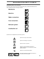
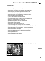
Water Heater Unit
Feel the drive
Thermo Top C Auxiliary
Heating
e1
00 0002
Installation Instructions
Mercedes-Benz E-Class BR 211 / CLS BR 219
Gasoline and diesel
from the 2003 model
For left-hand drive vehicles only
Not for AMG or AMG look
WARNING!
Hazard warning:
Incorrect installation or repair of Webasto heating systems may cause a fire or result
in the emission of carbon monoxide, which can be fatal. Serious or fatal injuries can
be caused as a result.
Specialist company training, technical documentation, specialized tools and
equipment are required to install and repair Webasto heating and cooling systems.
NEVER attempt to install or repair Webasto heating or cooling systems if you have not
successfully completed the company training and thereby acquired the required
technical skills or if you do not have access to the required technical documentation,
tools and equipment needed to carry out correct installation and repairs.
ALWAYS follow all Webasto installation and repair instructions and observe all
warning instructions.
Webasto does not accept any liability for defects and damage that are attributable to
an installation by untrained staff.
Doc. No.: 5001169A
Kit No.: 5001168A
Mercedes-Benz E-Class BR 211 / CLS BR 219
Table of Contents
Validity
2
Heater Unit / Installation Kit
3
Foreword
3
General Instructions
3
Special Tools
3
Explanatory Notes on the Document
4
Preliminary Work
5
Tips and Tricks / Preparing the Electrical
6
Preparing the Heater Unit / Installing the
Heater Unit
7
Electric diagram
8
Installing the Wiring harness /
Electrical Connection
9
T90 remote receiver /SPAL remote receiver 10
Routing the Fuel Pump Wiring Harness
11
Water diagram
12
Turning the Water Pump
13
Connecting the Heater Unit to the Water
Pump
14
Replacing the Switch Valve /
Installing the Coolant hoses
15 - 17
Installing the Fuel Line
18
Assembling Fuel Pump
19 - 20
Final Work
21
Validity
Manufacturer
Model
Daimler-Chrysler
Daimler-Chrysler
E Class
CLS Class
Engine type
Engine
200 CDI
220 CDI
270 CDI
280 CDI
280 CDI 4MATIC
320 CDI
320 CDI 4MATIC
400 CDI
420 CDI
200 NGT
200 K
240
240 4MATIC
280
280 4MATIC
320
320 4MATIC
350
350 4MATIC
500
500 4MATIC
Diesel / R4
Diesel / R4
Diesel / R5
Diesel / V6
Diesel / V6
Diesel / V6
Diesel / V6
Diesel / V8
Diesel / V8
Gasoline / R4
Gasoline / R4
Gasoline / V6
Gasoline / V6
Gasoline / V6
Gasoline / V6
Gasoline / V6
Gasoline / V6
Gasoline / V6
Gasoline / V6
Gasoline / V8
Gasoline / V8
Type
211
219
Power in kW
90
110
130
140
140
165
165
191
231
120
120
130
130
170
170
165
165
200
200
225
225
EG-BE No. / ABE
e1 * 2001 / 116* 0213
e1 * 2001 / 116* 0295
Engine capacity in cm³
2148
2148
2685
2987
2987
2987
2987
3996
3996
1796
1796
2597
2597
2996
2996
3199
3199
3498
3498
4966
4966
Vehicle and engine types as well as equipment variants, which are not listed in these installation
instructions, have not been tested. Installation according to these installation instructions may,
however, be possible.
2
Mercedes-Benz E-Class BR 211 / CLS BR 219
Heater Unit / Installation Kit
Amount
1
1
Description
Scope of delivery TT-C Diesel W211 / W219
Scope of delivery TT-C Gasoline W211 / W219
Order No.:
9014163 A
9014164 A
Foreword
These installation instructions apply to vehicles Mercedes-Benz E-Class BR 211 / CLS BR 219 with
Gasoline and dieselengines, for validity, see page 2 - as from model year 2003 and later, assuming
technical modifications to the vehicle do not affect installation, any
liability claims excluded. Depending on the vehicle version and equipment, modifications may be
with respect to these “Installation Instructions”.
However, the stipulations in the "installation instructions" and "operating and maintenance instructions"
for the Thermo Top C/P/E are to be observed in any event.
The corresponding rules of technology and any information from the vehicle manufacturer should be
observed during the installation work.
General Instructions
Installation should be carried out according to the general, standard rules of technology. Unless
specified otherwise, fasten hoses, lines and wiring harnesses to original vehicle lines and wiring
harnesses using cable ties.
Sharp edges should be fitted with edge protectors (split open plastic hose).
Spray unfinished body areas, such as for example bore holes, with anti-corrosion wax (Tectyl 100K,
Order No. 111329)!
After installation, release the auxiliary heater function using the DC Star diagnosis (coding).
Special Tools
- Torque spanner for 2.0 - 10 Nm
- Vise-grip wrench
3
Mercedes-Benz E-Class BR 211 / CLS BR 219
Explanatory Notes on the Document
To provide you with a quick overview of the individual working steps, you will find an identification mark
on the outside top right corner of the page in question.
Mechanics
Electrics
Water connection
Fuel connection
Exhaust system
Combustion air
Special features are highlighted using the following symbols:
Specific risk of injury or fatal accidents.
Specific risk of damage to components.
Specific risk of fire or explosion.
i
Reference to general installation instructions of
Webasto components or to the manufacturer's vehiclespecific documents.
Reference to a special technical feature.
The arrow in the vehicle icon indicates the position on
the vehicle and the viewing angle.
4
Mercedes-Benz E-Class BR 211 / CLS BR 219
Preliminary Work
-
Slide the passenger seat backwards as far as possible.
Remove the vehicle keys from the ignition.
Disconnect the battery. (in the trunk)
Remove the side cover of the fuse box on the driver’s side of the dash board.
Remove the footwell panel under the dashboard on the passenger side.
Remove the A-pillar panel in the passenger side.
Remove the floor cover in the passenger footwell area.
Loosen the footrest plate located behind this.
Remove the cover from middle console around the gear shift stick (optional).
Remove the A-pillar panel in the passenger side.
Loosen the cable conduit cover next to the fond armrest.
Open the hood.
Let off pressure in the cooling system.
Copy the factory number from the original type label to the duplicate type label.
Remove years that do not apply from the duplicate label.
Attach the duplicate label (type label) in the appropriate place.
Open the fuel tank cap, ventilate the tank.
Close the fuel tank cap again.
Remove the right front and rear wheels
Remove the front part of the right wheel house panel.
Loosen the front section of the wheel house panel and lift it to the back.
Remove the lower right section of the engine enclosure under the rocker panel (2 sections).
(CLS only) loosen the front grill
Loosen the bumper on the right side of the vehicle.
Remove right headlight (CLS: 2 screws on the top, 1 screw from the wheel house).
Remove the engine design cover (pull off).
Remove the covers in the left and right engine area (turn locks 90°).
Remove the combination filter housing (1 plastic nut, left and right snaps).
Remove the windshield wipers.
Pull off the gasket that runs across the water reservoir cover.
Remove the water reservoir cover, remove the drain hose.
Remove the windshield wiper arm and motor.
Heater Unit Installation Location
1 Heater unit
Installation
location
1
1
5
Mercedes-Benz E-Class BR 211 / CLS BR 219
1
2
Loosen the bumper on the side facing the
wheel well:
Loosen the screws, move the clamping bar to
the front and remove it.
1 Clamping bar
2 Bolt
3 Coolant hose to the heater unit (will be
added Later, not yet present during
disassembly)
Tips and
Tricks
3
2
To route wiring harnesses and wires through
grommets, cable ducts or tight areas, we
recommend using the mecanyl fuel line. This,
for example, is pushed through a cable duct
until the desired point is reached, the wiring
harness is fastened with insulation tape and
pulled behind.
Tips and
Tricks
1
Preparing the wiring harness
2
Remove the wiring harness twine between
the connection of the fuel pump plug and the
unwrapped section.
1 Beginning of the wrapped section
2 Disconnecting the fuel pump connector
3 Fuel pump connector (blue)
Removing
the
wiring
harness
twine
3
3
6
Mercedes-Benz E-Class BR 211 / CLS BR 219
Preparing the Heater Unit
1
2
Place the solenoid valve and bracket
on the stay bolts in the heater unit and
fasten with the flanged nuts.
Fasten the preassembled coolant hose with
the spring band clamp to the solenoid valve.
Replace the connector on the solenoid valve.
1 Solenoid valve connector
2 Preassembled coolant hose with clamp
3 M6 flanged nuts [3x]
3
Connecting the
solenoid
valve
4
Connect the mecanyl fuel line to the heater
fuel line nipple with the
hose section and clamp.
1
1 Fuel line
2 Universal clamp
(white color identification) [2x]
3 Hose section
3
Connecting
the fuel
line
2
5
Installing the heater unit
Loosely pre-assemble the solenoid valve
bracket on the wheel well
with two screws.
2
1
1 M6x12 collar screws [2x]
2 Solenoid valve bracket
Installing
the
solenoid
valve
6
1
Loosely pre-assemble the heater unit
bracket on the bumper cross member with
two screws.
Tighten all fastening bolts.
Plug the wiring harness connector into the
heater.
Route the wiring harness to the right
suspension strut mount.
2
Assembling the
heater unit
1 M6x12 collar screws [2x]
2 Heater unit bracket
7
7
Mercedes-Benz E-Class BR 211 / CLS BR 219
Electrical Connections
CAN junction
Ground connection
1 Heater wiring harness
2 CAN plug connector
1 Grounding point in passenger foot area
2
1
1
8
9
Wiring
harness
installation
diagram
2
1
3
2
1
6
5
10
Dashboard fuse box
1 Fasten the heater unit fuse holder on the free
slot in the left row, fifth from the top
(position 25)
2 Dashboard fuse box left
4
11
T90 and SPAL remote control
elements
(schematically pre-assembled)
1 Heater harness
2 Remote antenna
3 SPAL receiver
4 Remote harness
5 T90 remote receiver
6 Y-adapter harness
8
Mercedes-Benz E-Class BR 211 / CLS BR 219
Installing the wiring harness
1
Unclip the harness conduit cover on the
right suspension strut mount, remove the
harness grommet from the guide. Cut the
side of the grommet and insert the Webasto
wiring harness. Seal the grommet with
adhesive sealant and reinstall in guide.
Wiring
harness
routing
1 Webasto wiring harness
2 Cut open grommet
C
12
2
The figure shows coolant hose C covered
with braided hose protection.
Route the wiring harness under the
hoses to the rear bulkhead.
Cut open the rubber sleeve.
Route wiring harness to passenger
compartment.
Seal the protective rubber sleeve with
sealant.
1
1 Protective rubber sleeve
2 Wiring harness
2
Wiring
harness
routing
13
Make electrical connection
1
2
Place wiring harness in passenger
compartment: Insert CAN plug in the plug
connector. Secure the ground cable to
existing ground point, route the fuse holder
behind the dash board to the fuse box, route
the fuel pump connector to the cable conduit
in the rocker panel, leave the wiring harness
for the T90 remote receiver in the foot area,
separate the six-pin plug from the wiring
harness.
3
14
2
1
Distribution of
wiring
harnesses
1 Footrest plate
2 CAN plug connector
3 Grounding point
Connect the red and brown wires from the Y
adapter to the wires of the same color in the
remote wiring harness.
Connect the yellow wire from the Y adapter to
the gray-blue wire in the remote wiring
harness.
Crimp and shrink the connectors.
Y- adapter
connection
1 Connector for SPAL receiver wiring
harness
2 T90 remote connector (Y adapter)
3 Crimp shrink connectors [3x]
3
15
9
Mercedes-Benz E-Class BR 211 / CLS BR 219
T90 Remote Receiver
1
Attach Velcro strips to the receiver.
1 Receiver
2 Velcro strips
T90
Remote
preparation
2
16
1
2
3
SPAL Remote Receiver
1 Receiver antenna
2 SPAL remote receiver
3 Remote harness from Y-adapter harness
SPAL
Remote
preparation
17
1
2
Note:
Note the chapter “Final work“on
page 22“
Fasten the T90 remote receiver on the rear
side of the glove compartment.
Fasten the SPAL remote receiver next to the
T90 remote receiver using nylon wire ties.
1 Glove compartment housing
2 T90 remote receiver
T90 / SPAL
remote
receiver
assembly
18
Glue the SPAL remote receiver antenna to
the black area on the windshield.
1
1 Windshield antenna
Antenna
installation
19
10
Mercedes-Benz E-Class BR 211 / CLS BR 219
Route the wiring harness for
the fuel pump
1
Route the connector for the wiring harness for
the fuel pump through the cable conduit to the
rear seat bench.
Route behind the back cover next to the arm
rest to the plug connector.
Place
in cable
conduit
1 Cable conduit cover
2 Rocker panel cable conduit
2
20
Remove the red gasket piece from the free
slot in the terminal strip (no longer needed).
Insert the connector for the fuel pump wiring
harness in the slot.
2
1 Connector for the fuel pump wiring harness
2 Wheel case terminal strip
1
Connector
for fuel
pump in
passenger
compartment
21
Plug the connector on the short wiring
harness to the fuel pump from the
wheelhouse to the corresponding slot.
1
1 Plug
Fuel
pump
connector
in wheel
house
22
Open the fastening lugs for the wiring
harness guide.
Route the wiring harness down through the
guide to the fuel pump and fasten.
1 Wiring harness guide fastening lug
1
Wiring
harness
guide in
the wheel
house
23
11
Mercedes-Benz E-Class BR 211 / CLS BR 219
Water Connection
Attention:
Any coolant running off should be collected using an appropriate container!
Install hoses so that they are kink-free. Unless specified otherwise, always fasten using cable ties.
Position spring band clamps so that no other hose can be damaged!
The connection is based on the following diagram:
All vehicles
Heat
Wärmeexchanger
tauscher
Water
installation
diagram
Ø 23
B
C
Ø 22
Motor
A
Ø 18/18
Ø 22
All undesignated clamps are Ø 25mm spring band clamps!
All undesignated coolant hose couplers are Ø 15x18.
12
Mercedes-Benz E-Class BR 211 / CLS BR 219
1
Route the fuel line under the air intake
silencer to the wheel house cross member.
Fasten to cross member with it two fastening
clips and route to the wheel house.
1 Fastening clips [2x]
2 Fuel line
Fuel line
installation
2
24
Water Connection
Disconnect both coolant hoses to the original
vehicle electric water pump with pliers and
remove.
Pull the plug off.
1 Water pump connector
2 Water pump
2
1
1
Water
pump
preparation
25
Turn the water pump in the bracket about
180°.
2
Check that the hose supports move easily to
the lines in the ABS unit.
Replace the connectors.
1 Hose supports
2 Water pump connector
Turning the
water
pump
26
1
2
3
Shorten the enclosed braided hose protection
by 380 mm.
From this 380 mm long piece, cut off
two 100 mm long pieces.
Place one 100 mm long piece on the hose
to the mechanical water pump.
Insert the coolant hose coupler and fasten
with a clamp.
4
1
2
3
4
Coolant hose coupler 18x18
Spring band clamp Ø25 mm
Braided hose protection 1=100 mm
Hose to the mechanical water pump
Coolant
hose
preparation
27
13
Mercedes-Benz E-Class BR 211 / CLS BR 219
Connect the disassembled coolant hose back
on the electric water pump as shown in
Figure 28.
1 Water pump
2 Coolant hose
1
2
Assembling the
coolant
hoses
28
Put the braided hose protection on the end of
the moulded hose.
Pre-assemble two clamps.
1 Braided hose protection 1=100 mm
2 Spring band clamps Ø25 mm [2x]
A Moulded hose
1
A
Coolant
hose
preassembly
2
29
Before connecting, fill the coolant hoses with
coolant. Connect the preassembled coolant
hose to the solenoid valve. Connect the other
end of the hose to the mechanical water
pump.
1
2
A
30
Fasten moulded hose to the original vehicle
stay bolts with the tube clamp.
Fasten the preassembled hose from the
heater unit coolant inlet to the free supports
on the water pump.
Assembling the
coolant
hoses
1 Hose for heater unit coolant inlet
2 Rubberised tube clamp Ø25, nut M6
A Moulded hose
1 Hose for heater unit coolant inlet
2 Hose to the mechanical
water pump connected with
moulded hose A
2
1
Assembling the
coolant
hoses
31
14
Mercedes-Benz E-Class BR 211 / CLS BR 219
Replacing the Switch Valve
1
Loosen the hose on the top
of the switch valve on the rear bulkhead
and loosen the plug.
Loosen the hose connections by
pulling out the spring wires [3x].
Remove the rubber sleeve.
Remove the valve.
2
Removing
switch
valve
1 Protective rubber sleeve
2 Engine outlet hose
32
1
B
2
33
Before connecting, fill the coolant hoses
with coolant!
Install new switch valve
(5 connections).
Replace protective rubber sleeves.
Check that the connections are
completely locked.
Reinstall the series coolant hose.
Fasten the additional moulded coolant
hose with clamps and move to the
right.
Switch
valve
assembly
B Moulded hose, spring band clamp Ø23 mm
1 Series coolant hose
2 Switch valve, 5 connections
Create coolant connections
1
Route moulded coolant hose along rear
bulkhead.
Position coolant hose as low as possible.
1 Switch valve, 5 connections
B Moulded hose
Routing
the coolant
hose
B
34
Route the moulded coolant hose under the
guide in the bleed hose from the coolant
reservoir.
1
1 Bleed hose guide
B Moulded hose
B
Routing
the
Coolant
hose
35
15
Mercedes-Benz E-Class BR 211 / CLS BR 219
Place the moulded coolant hose in the gap
in the windshield fluid container and
then along the wiring harnesses under
the container shackle.
B
1 Windshield fluid container shackle
B Moulded coolant hose
1
Routing
the coolant
hose
36
1
2
3 4
Slide the long remnant of the braided hose
protection on hose C l=800 mm.
On one side, slide on the red rubber insulator.
On both sides, insert the coolant hose
couplers and fasten with clamps.
1
2
3
4
Spring band clamps Ø25 mm [2x]
Braided hose protection
Rubber insulator, red
Coolant hose coupler 15x18 [2x]
Coolant
hose
preassembly
37
B
2
1
Connect the preassembled coolant hose to
the moulded hose and fasten with
clamp.
Remove the filling from the conduit.
Move the coolant hose to the front through
the guide.
Clip on the conduit cover.
1
B
2
C
C
Conduit cover
Moulded hose
Spring band clamp Ø22 mm
Coolant hose
Place
coolant
hose in
guide
38
Route coolant hose under the cross rail
according to Figure 39.
(Figure shows the CLS, always check
for access to the headlight!)
1
1 Coolant hose C
Installing
coolant
hose
39
16
Mercedes-Benz E-Class BR 211 / CLS BR 219
Route the coolant hose on the side over
the bracket and down into the fender.
(Figure shows CLS, always check for
access to the headlight!)
Routing
the coolant
hose
40
Connect the coolant hose to the
preassembled hose on the solenoid valve.
C
C Coolant hose
2 Spring band clamp Ø22 mm
3 Preassembled hose on solenoid
Coolant
hose
connection
2
3
41
17
Mercedes-Benz E-Class BR 211 / CLS BR 219
Fuel Connection
Remove the vehicle's fuel tank cap, ventilate the fuel tank and reinstall fuel tank cap.
CAUTION!
Catch any fuel running off with an appropriate container.
Install the fuel line so that they are protected from impact by rocks!
Unless specified otherwise, always fasten using cable ties.
Fit the fuel line and wiring harness with edge protectors around sharp edges.
Attention:
The wiring harness to the fuel pump should be installed based on the wiring harness installation
diagram.
1
2
Installing the fuel line
3
Remove the round protective rubber sleeve in
the side of the frame side rail and the long
protective rubber sleeve on the underside of
the frame side rail and punch a Ø 5mm hole.
Pull the round sleeve over the fuel line and
insert the fuel line into the frame side rail
through the round opening.
Slide on two rubber sliders on the fuel line
to protect from wear.
42
Insert the
fuel line
in the
frame
side rail
1 Round protective rubber sleeve
2 Fuel line
3 Rubber sliders [2x]
Route the fuel line out of the long opening
in the frame side rail.
Slide of grommet and insert in opening.
2
1 Fuel line
2 Long grommet
1
Routing
the
fuel line
43
Replace the four single line clips with
double line clips.
Clip in the brake line and fuel line.
Route the fuel line back to the installation
location for the fuel pump.
1 Double line clips [4x]
2 Fuel line
2
Fastening
the
fuel line
1
44
18
Mercedes-Benz E-Class BR 211 / CLS BR 219
1
2
3
Assembling the fuel pump
4
1
2
3
4
Fuel line coupler 90°
Fuel pump
Rubber bracket
Universal clamp Ø10 mm,
(white color identification) [4x]
5 Fuel line coupler [2x]
6 Mecanyl fuel line 1=130 mm
6
Fuel pump
preassembly
5
45
Install the fuel pump mounting bracket (with
M6x25 collar screw) on the original vehicle
bolts with plastic nuts.
1
1 M6x25 collar screw
2 Plastic nuts [2x]
3 Fuel pump mounting bracket
3
2
Installing
the fuel
pump
mounting
bracket
46
Note the installation position of the metering
pump, see the "Installation Instructions".
Secure the fuel pump bracket to the M6x25
collar bolt with nut provided.
2
1
1 Flanged nut M6
2 Bracket with fuel pump
Assembling the fuel
pump
47
1
Remove the cap and pull the end of the fuel
nipple out of the fuel tank.
Cut the end of the fuel nipple off with a sharp
knife. Immediately connect the fuel line
between the fuel tank nipple and the suction
side of the fuel pump and tighten clamp.
1 Fuel nipple on the tank
Cutting off
the end of
the fuel
nipple
48
19
Mercedes-Benz E-Class BR 211 / CLS BR 219
Insert a screw driver in the fuel pump
mounting bracket hole and bend the strap to
align it for free access to the fuel pump from
the adjacent components.
2
1 Suction side of the fuel line
2 Fuel pump mounting bracket
1
Align the
fuel pump
bracket
49
Cut the fuel line on the fuel pump into
sections and connect to the fuel pump outlet
(side with connector) with fuel line coupler
and clamps.
Route the connector for the fuel pump
to the fuel pump and connect.
1
1 Universal clamps Ø10 mm,
(white color identification) [2x]
2 Fuel pump connector
Assembling the fuel
pump
connector
2
50
1
2
3
Install the fuel line along the original vehicle
lines.
Where the hose sections (wear protection)
are already located,fasten with cable ties.
Use split fuel hose as an additional wear
protection if necessary.
1 Cut open end piece
2 Cable ties
3 Protection from wear (present)
Fuel line
installation
51
20
Mercedes-Benz E-Class BR 211 / CLS BR 219
Final Work
WARNING!
Reassemble disassembled components in reverse order.
Check that all hose lines, hose, spring band clamps and universal clamps, and all electrical
connections are securely fastened.
Secure all loose lines using cable ties.
Check and adjust any disassembled or loose headlights after installation.
Spray heating unit components with anti-corrosion wax (Tectyl 100K, Order No. 111329).
i
- Start engine, bleed coolant circuit according to the vehicle manufacturer's specifications, top up
with coolant.
- Warning! Only use manufacturer-approved coolant.
- Check the coolant system for leaks according to the manufacturer’s instructions.
- After assembly, follow the manufacturer’s instructions for star diagnosis to activate the auxiliary
heater.
- Check that the auxiliary heating operates properly, see operating instructions / installation
instructions.
Attach the "Switch off auxiliary heating before re-fuelling" sticker in the tank flap or the left side of the
B-pillar.
Programming the T90 Remote Receiver
Attention
Ensure the SPAL receiver is plugged into the Y-adapter harness going to the T90 remote receiver.
Read through all steps before beginning programming procedure, some of the steps are time critical.
-
Connect the battery.
Disconnect the harness going to the T90 remote receiver and reconnect after 5 seconds.
Within 7 seconds, press the “on” button on the SPAL hand-held transmitter for about 1 second.
Check for proper operation of the transmitter and repeat procedure if necessary.
Enabling the Factory Equipped Timer Function
The Mercedes E Class comes factory equipped with a HVAC controller that can be programmed to
control the Webasto heater On / Off times. STAR Diagnostics must be used to program this feature for
the heater. Only a certified Mercedes dealership has the necessary diagnostic tool and information to
properly set up these heater functions.
Refer to “Auxiliary heating / ventilation” in the vehicle’s owners manual for specific instructions on how
to set heater On / Off times.
21
Mercedes-Benz E-Class BR 211 / CLS BR 219
NOTES:
22
Mercedes-Benz E-Class BR 211 / CLS BR 219
Documentation Feedback Form
Detailed user feedback is extremely valuable to us in producing accurate, comprehensive, and useful documentation
Please complete the relevant parts of the form below; your comments and suggestions will help us improve our
documentation. Thank you.
Unsatisfactory
Excellent
Please rate the overall usefulness of the documentation.
1
2
3
4
5
Rate the completeness and clarity of the instructions:
did the procedures provide enough detail?
1
2
3
4
5
What could be added or clarified?
Please list any other comments, concerns, or suggestions.
Please provided contact information below.
Name:
Company Name:
City / State:
Phone:
Email:
Mail to:
Webasto Product N. A., Inc.
15083 North Road
Fenton, MI 48430
Attention: Documentation
Group
or
Fax to: (810) 593-6137
23
F e e l t h e d r iv e
Webasto Product N.A., Inc.
Technical Assistance Hotline
USA:
(800) 555-4518
Canada: (800) 667-8900
Org.07/2006
Rev. N/A P/N 5001169A
www.webasto.us
www.techwebasto.com