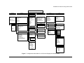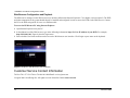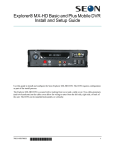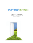
1
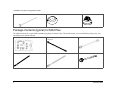
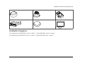
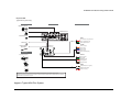
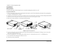
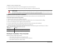
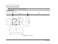
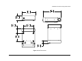
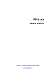
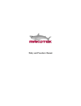
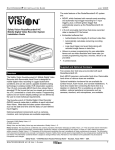
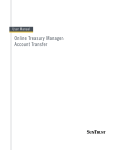
Explorer™ MX4 Basic and Plus Mobile DVR
Installation and Quick Configuration Guide
The MX4 DVR is secured with a locking front cover and a cable cover. Two cable grommets (and two knockouts) on the cable cover allow
for wiring to enter from the left side, right side or back of the unit. The DVR can be installed in a horizontal or vertical installation.
Check that you have all the system components and inspect the units for any scratches or damage before installing.
You will need these materials to complete the installation:
•
•
DVR keys for securing the removable hard drive
Front cover keys for securing the removable front cover
•
# 2, Phillips screw driver for 6-32 x 3/16 screws
Package Contents (typical) for MX4 Basic
The contents of a typical basic installation package are listed below. The actual contents of your installation package may vary, depending
on the options selected.
Explorer MX4 DVR with locking front cover and cable
cover, media cartridge, and mounting plate
700-0077 R002
Cameras (up to 4) and extension cable
Ignition harness wire
1
Installation and Quick Configuration Guide
Alarm button and cable
Remote microphone (optional)
IR Illuminator (optional)
Package Contents (typical) for MX4 Plus
The additional items for a typical Plus installation package are shown below. The actual contents of your installation package may vary,
depending on the options selected.
Smart-Link™ module for signal interfaces
Smart-Link-to-DVR connection harness (identical
connectors)
Speed cable
Alarm input harness
Signal harness
Diagnostic indicator/Alarm button
2
700-0077 R002
Installation and Quick Configuration Guide
Remote microphone (optional)
IR Illuminator (optional)
Inertia sensor (optional)
Smart-Reach™ Mobile (optional)
GPS receiver (optional)
LCD monitor
Installation Diagrams
For installing the typical MX4 Basic system, see Figure 1, “Typical MX4 Basic System” on page 4.
For installing the typical MX4 Plus system, see Figure 2, “Typical MX4 Plus System” on page 5.
700-0077 R002
3
Installation and Quick Configuration Guide
Explorer® MX4
Typical Basic System Setup
Peripherals
Vehicle Electrical Interface
Seon System
Supports Four Cameras
IR Illuminator
MX4 DVR Rear Panel
Remote Microphone*1
Alarm Switch
5A
POWER
Vehicle + 12V (red)
1A
3 wires
Vehicle Switched + 12V (yellow)
Battery Negative (black)
LCD Monitor*2
*1 The optional remote microphone connected to AUD IN1 (or AUD IN2) can only be used if the camera connected to Camera 1 (or Camera 2) does not have a microphone.
*2 The LCD Monitor can be used for the front or back panel.
Part Number 700-0086 R001
Figure 1 Typical MX4 Basic System
4
700-0077 R002
Installation and Quick Configuration Guide
Explorer® MX4
Typical Plus System Setup
Peripherals
Vehicle Electrical Interface
Seon System
Supports Four Cameras
IR Illuminator
MX4 DVR Rear Panel
Remote Microphone*2
SPEED
GPS Receiver
Diagnostic Indicator/
Alarm Button
Red - Call Seon if using hall sensor
Green - Speed sensor high
Black - Speed sensor low
3 wires
*1
ALARMS
Smart-Link™
Alarm 1 (orange)
Alarm 2 (blue)
Alarm 3 (violet)
Alarm 4 (gray)
Accessories
4 wires
Smart-Reach® Mobile (Wi-Fi)
Alarm 1-4 Ground (black)
SIGNALS
Left Turn (black)
8 wires
Stop (green)
Brake Signal (red)
5 wires
Warning (brown)
Inertia Sensor
Right Turn (white)
1A
POWER
Vehicle Switched + 12V (yellow)
LCD Monitor*3
3 wires
Battery Negative (black)
5A
Vehicle + 12V (red)
*1 For speed tracking, use a GPS receiver or speed sensor. For ease of installation and better speed tracking, Seon recommends using a GPS receiver.
*2 The optional remote microphone connected to AUD IN1 (or AUD IN2) can only be used if the camera connected to Camera 1 (or Camera 2) does not have a microphone.
*3 The LCD Monitor can be used for the front or back panel.
Part Number 700-0085 R001
Figure 2 Typical MX4 Plus System
700-0077 R002
5
Installation and Quick Configuration Guide
Installation
DVR Installation
The DVR typically ships with the locking front cover on and the mounting plate and cable cover off.
To install the MX4 DVR:
1 Select an appropriate mounting location and orientation, horizontal or vertical. For the dimensions and location of the mounting holes,
see Figure 6 “MX4 Dimensions” on page 11.
2 Unlock the door lock and remove the front cover from the unit to access the front panel. Verify there is a media cartridge inside the DVR.
3 Determine where the wiring and camera cables will enter the unit: on the left side, right side or back.
4 Remove the necessary knockout (s), insert plugs and cable grommets.
Media cartridge
Door lock
Locking front cover
(reversible)
Mounting plate
Cable cover
Cable grommets
Knockouts
Figure 3 MX4 DVR components
5 Use the mounting plate to mark the desired position of the DVR and drill the four mounting holes. The flange secures to front of the
DVR, the tray spring tab attaches to rear.
6 Fasten the mounting plate to the mounting surface with the four #10 × ¾ sheet metal screws or #10 × 1" self-drilling screws.
7 Secure the DVR to the mounting plate with the two screws.
8 Connect the necessary components.
6
700-0077 R002
Installation and Quick Configuration Guide
Camera Installation
Install the cameras according to the documentation that shipped with the product.
CAUTION
Route the wiring and cables away from sharp edges that might damage the insulation. Avoid sharp bends in the cable.
Feed the cable through one of the large cable grommets one at a time, or cut the grommet at the top and slide the cables into the grommet.
MX4 Basic: Alarm Button Installation
To install the alarm button:
1 Mount the alarm button into a ½" hole, and attach to the alarm input harness using the butt spice connectors.
2 Attach the black wire of the alarm button to the black wire of the alarm input harness.
3 Attach the blue wire of the alarm button to the red wire in the alarm input harness.
4 Connect the alarm input connector to ALARM INPUT on the DVR.
Figure 4 Alarm Button and Alarm Input Harness
MX4 Plus: Smart-Link™ Installation
Important:
•
•
Choose a dry location with easy access to the electrical panel and cable connections to mount the Smart-Link.
Always use the supplied fuses to provide over-current protection on the system wiring. The harness kit includes two fuses for the two 12V lines
required to complete this installation.
To mount the Smart-Link:
1 Mount the Smart-Link using the four #10 × ¾" sheet metal screws or the four #10 × ¾" self-drilling screws. See Figure 5.
700-0077 R002
7
Installation and Quick Configuration Guide
2 Connect the constant, switched 12 volt lines and grounds wires as shown in Figure 2.
3 Connect all other optional items such as speed, GPS, signals, diagnostic, or alarms to Smart-Link.
CAUTION
It is recommended to connect the constant power and ground wires as close to the battery as possible. Ensure the connections are safe
and secure to reduce potential corrosion or premature wear out which may compromise performance.
Diagnostic Indicator/Alarm button Installation
Pressing the alarm button of the diagnostic indicator/alarm button causes an alarm event to be recorded by the DVR.
To install the diagnostic indicator/alarm button:
1 Determine proper location before drilling mounting holes.
2 Drill a ¾" hole in the desired location. Ensure that the area behind the hole is clear of obstructions before drilling.
3 Remove the mounting nut from the diagnostic indicator/alarm button.
4 If you have purchased the video recording label, install the label between the button and the dashboard.
5 Feed the connector and cable through the mounting hole and reattach the nut.
The button corresponds to Alarm 1 on the Smart-Link alarm harness. The indicator ring shows the DVR status. See Table 1.
Table 1 Diagnostic indicator/alarm button ring color
Ring Color
Function
No green light
No power to the DVR, or ignition is not on.
Flashing green
The DVR is powered up, but not recording.
Solid green
The DVR is powered up and recording.
Hardware Installation Final Checklist
Harnesses (Camera, recorder, and accessories)
•
•
•
8
Check that the cables and harnesses are properly secured.
Check that sharp metal edges are not touching the cables or harnesses.
Check that the connections are solid (no shorts).
700-0077 R002
Installation and Quick Configuration Guide
Cameras
•
•
•
•
Check for tight mount.
Check the internal harness connections.
Check that the lid is properly seated on the gasket and secured tightly.
Check camera (s) field of view.
DVR
•
•
•
Check for tight mounting of hardware.
Confirm that the cable grommet is properly installed.
Check that all connections are tight.
System
•
•
•
•
•
•
•
•
Install the fuses.
Plug the video monitor into the DVR and power up the system.
Confirm that all the cameras and audio sources are operating properly.
Confirm that all the status indicators react properly: LAN, HDD, PWR, TEMP, VOLTAGE.
Switch to temporary power by pressing the front panel STOP/TEMP POWER button with vehicle ignition turned OFF.
Test audio/video record and test audio/video playback.
Configure the menus via the remote control or trackball mouse, or Web-based configuration per the end-user specifications. See
Explorer MX4 Mobile DVR System User Guide (document part number 700-0075).
Fasten and lock the front cover. Fasten the cable cover on the unit using the screws provided.
Accessories
•
•
•
•
•
GPS Receiver Installation – for more information, see the product documentation.
TR-INR Inertia Sensor – for more information, see the product documentation.
LDC Monitor – for more information, see the product documentation.
Smart-Reach Wireless Network – contact your sales representative at Seon Design for wireless network options.
CAN Network – contact your sales representative at Seon Design to discuss the CAN interface.
700-0077 R002
9
Installation and Quick Configuration Guide
Physical Specifications
Important: Specifications are subject to change without notice.
Smart-Link Module
Table 2 Physical Specifications
Smart-Link
Weight and Material
MX4
9 oz (255 g), steel, powder coated black paint
5.3 lb (2.4 kg) including lockbox, steel, powder coated black paint
Figure 5 Smart-Link Module
10
700-0077 R002
Installation and Quick Configuration Guide
9
3
7
in
16
183 mm
2
2
11 in
16
246 mm
11
in
16
68 mm
5
in
16
59 mm
5
9
in
32
134 mm
4 5 in
32
105 mm
1
7
in
16
37 mm
Figure 6 MX4 Dimensions
700-0077 R002
11
Installation and Quick Configuration Guide
Configuration
The MX4 can be configured by two methods:
•
On Screen Display (OSD) Configuration and Playback
Connect to VIDEO OUT on the MX4 front panel with an LCD monitor and use the trackball pointing device or the remote control to set
configuration settings. For more information, see the Explorer MX4 Basic and Plus Mobile Digital Video Recording System User Guide,
document part number 700-0075.
• Web Browser Configuration and Playback
Web Browser Configuration and Playback uses an Ethernet connection with a laptop. See page 14.
The MX4 Configuration Main Menu shown in Figure 7 applies to the on screen display configuration and to the Web browser
configuration.
12
700-0077 R002
Installation and Quick Configuration Guide
Explorer MX4 DVR Configuration Main Menu
Time/Date
Title/Display
Alarm/Signal
Record
Network
System
Alarms
Time Format
Time
Date Format
Date
Auto Daylight Savings
DST Settings
Start Date
From
To
End Date
From
To
Main Title
Main Title Display
Camera 1
Camera 2
Camera 3
Camera 4
Alarm
Alarm Duration
Alarm Input
Pre-Alarm Record
Channel (1 – 4)
Speed
Quality
Resolution
Email
Wake
Monitor Settings
Front Default Settings
Rear Default Settings
Display Switch
Switch To
Switch On
Alarm
Repeat Record
Record Delay-On Time
Record Delay-Off Time
Power Delay-Off Time
Alarm Partition Size
Overwrite Alarm Protection
Camera
Channel/Speed/Quality/
Resolution
Audio Recording 1/2/3/4
Voltage Display
Time/Date Display
HDD Size Display
% Full Display
Alarm Count Display
Internal Temperature Display
Hard Drive Temperature
User Levels (1- 6)
Name/Password/Level
Signals (1 – 10)
Label/Level/Alarm
DDNS Settings
Record 2
Channel/Speed/Quality/
Resolution
Diagnostic Display
Setting Type
IP Address
Subnet Mask
Default Gateway
DNS Server
MAC Address
Speed
Speed Display
Speed Units
Speed Pulse Count
Timer (1 – 10)
Day/Start/End/Set
Calibrate
GPS
GPS Display
GPS Time
UTC Reference
Fencing Alarm
Coordinate Style
Top Left: LAT
: Long
Bottom Right: LAT
: Long
DDNS Server
User Name
Password
Record ID
FQDN Host Name
Disk Full
HD Failure
Password Enable
Password
Audio Output Channel
Program Update
Load Configuration from USB
Store Default Configuration to
USB
Firmware Update
Format Hard Drive
Load
Store
Update
Format
Email
SMTP Server
SMTP Port
Password
User Name
Pasword
Sender Email
Receiver Email
Subject
One Touch
One-Touch Download
Download All Alarm Data
From: Date
: Time
To : Date
: Time
Figure 7 Configuration Main Menu for On Screen Display and Web Browser
700-0077 R002
13
Installation and Quick Configuration Guide
Web Browser Configuration and Playback
The MX4 can be managed via the Web browser user interface (Microsoft® Internet Explorer® 7.0 or higher versions required). The DVR
and other components in the system should already be installed and configured in order to access the DVR via the Web browser. Connect
the PC to the DVR using an RJ-45 cross-over Ethernet cable.
To access the DVR from a PC using Internet Explorer:
1 Open Internet Explorer from your PC.
2 In the address bar of the Web browser, type in the following information: http://LAN or IP address of your DVR. For example,
http://192.168.1.201. Figure 8 show the logon menu.
3 Enter a default User Name and Password to access the Web browser user interface. Click Login or press enter on the keyboard.
‘
Figure 8 Explorer Web Browser User Interface
Customer Service Contact Information
Toll free Tel 1-877-630-7366 or Tel 604-941-0880 Email: [email protected]
©August 2009. Seon Design Inc. All rights reserved. Printed in Canada www.seon.com
14
700-0077 R002