1
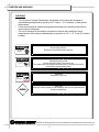
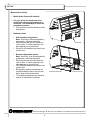
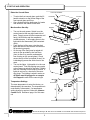
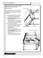
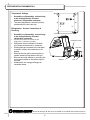
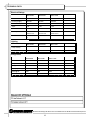
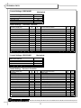
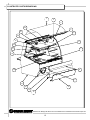
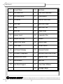
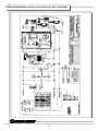
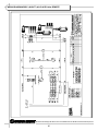
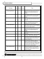
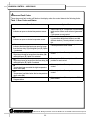
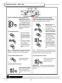
READ AND SAVE THESE INSTRUCTIONS
OPERATING
MANUAL
PN 99515
OPEN REFRIGERATED
SERVICE
REFRIGERATED
SELF-SERVICE
/ NON-REFRIGERATED
MERCHANDISER
MERCHANDISER
Model RB5C4848LR
Model RB5C5948LR
Model RB5C7748LR
Model RB5C4848RR
Model RB5C5948RR
Model RB5C7748RR
48”L* x
56”L* x
77”L* x
48”L* x
56”L* x
77”L* x
38 1/8”D** x 47 1/4”H
38 1/8”D** x 47 1/4”H
38 1/8”D** x 47 1/4”H
38 1/8”D** x 47 1/4”H
38 1/8”D** x 47 1/4”H
38 1/8”D** x 47 1/4”H
*Includes end panels.
**Without Package Ledge or Cutting Board
R
888 Porter Rd. Muskegon, MI 49441 Phone: 231.798.8888 Fax: 231.798.4960 www.structuralconcepts.com
Rev C Date:
L:\Inst & Oper Man\Renaissance\RB5C(L)48LR&RR Oper Man 99515.pub
07.19.2006
TABLE OF CONTENTS
OVERVIEW AND WARNINGS .. .…………………………..…………………..…….………….....…..
3
MERCHANDISER SET-UP ………….. …..….…………………...………...…..………………………
4
START-UP AND OPERATION ...…………….. …..….…………………...………...…..………………
5
MAINTENANCE FUNDAMENTALS ……………………………………………………………..………
6
ELECTRICAL FUNDAMENTALS ……………. …..….…………………...………...…..………………
8
REFRIGERATION FUNDAMENTALS …………………….………………………………………..…... 11
TECHNICAL DATA ………………………………………………………………………………….……
12
ILLUSTRATED PARTS BREAKDOWN …………………….…………………………………………... 15
PARTS LIST ..………………………………………………………………………………………………
17
TROUBLESHOOTING ……………………………………………………………………………………
18
WIRING DIAGRAM RB5C (48/59/77) 48 LR & RR Units SELF CONTAINED ………………….….
19
WIRING DIAGRAM RB5C (48/59/77) 48 LR & RR Units REMOTE …………...………………….…
20
CLEANING SCHEDULE ..…………………………………………………………...……………………
21
JOHNSON CONTROL ALARM and FAULT CODES …………………………..……………………..
22
JOHNSON CONTROL PROGRAMMING ………………….………………………………………..….
WARRANTY ..………………...……………………………………………………..……………………..
24
TECHNICAL SERVICE .…………..……………………………………………….……………….…..…
25
R
888 Porter Rd. Muskegon, MI 49441 Phone: 231.798.8888 Fax: 231.798.4960 www.structuralconcepts.com
2
OVERVIEW AND WARNINGS
OVERVIEW
•
•
•
*The Structural Concepts Renaissance refrigerated service cases are designed to
merchandise packaged bakery products at 5° Celsius / 41° Fahrenheit or less product
temperatures.
These cases should be installed and operated according to the following instructions to
insure proper performance.
This unit is designed for the display of products in ambient store conditions where
temperatures and humidity are maintained at a maximum of 24° C / 75° F and 55% relative
humidity.
WARNING
Risk of Electric Shock.
Disconnect Power Before Servicing Unit
WARNING
ELECTRICAL
HAZARD
WARNING
KEEP HANDS
CLEAR
WARNING
Hazardous Moving Parts.
Do Not Operate unit with covers removed.
Fan blades may be exposed when deck panel is removed. Disconnect
power before removing deck panel.
WARNING
Evaporator Tray is Hot
WARNING
HOT
SURFACE
CAUTION
CAUTION
Lamps have been treated to resist breakage and must be replaced with a
similarly treated lamp.
R
888 Porter Rd. Muskegon, MI 49441 Phone: 231.798.8888 Fax: 231.798.4960 www.structuralconcepts.com
3
SET-UP
Merchandiser Set-Up
•
Mobile Units (Cases with Casters)
•
For your safety, the equipment is furnished with a properly grounded cord
connector. Do not attempt to defeat the
grounded connector.
• Plug cord into a certified electrical outlet
with ground.
•
Stationary Units
•
•
•
•
•
•
•
•
Self-contained refrigeration.
Note: Servicing to be accomplished by
refrigeration / electrical contractor.
Removing the rear grill will expose access to the a 3” service opening in the
base adjacent to a junction box.
Electrical 120v leads are provided in the
junction box.
Remote refrigeration system.
Note: Servicing to be accomplished by
refrigeration / electrical contractor.
Removing the rear grill will expose access to the a 3” service opening in the
base adjacent to a junction box.
120v Electrical leads are provided in the
junction box.
Refrigeration stub up connections are
provided inside the case, from the rear
and in back of the electrical box.
To facilitate maintenance see electrical
section for electrical box removal.
Rear Grill
Evaporator Stub Ups
3” Service Access
R
888 Porter Rd. Muskegon, MI 49441 Phone: 231.798.8888 Fax: 231.798.4960 www.structuralconcepts.com
4
START-UP AND OPERATION
Raise the Curved Glass
•
•
Front Curved Glass
To raise the front curved glass, grab the lift
handle extrusion on the bottom edge of the
front curved glass and lift up.
Gas cylinders hold the glass open for hands
free access to the interior of the case.
•
•
•
Coil Fan
Deck Pan
Register
Merchandiser Start-Up
•
Lift Handle
Turn on the main power. Switch is on the
control panel at the rear right hand side of
base. Supply power will start evaporator coil
fan(s), the front fan and the evaporator/
condensate pan. It will supply power to the
light switch and thermostat, (self-contained
units).
From the front of the case, raise the deck
pans and check to see that the coil fans are
all functioning properly.
On the top of the front panel a register directs air flow provided by the front fans,
(front air flow is to prevent condensation
from forming on the curved glass). Check
across the top of the front panel to see if air
is discharging across the entire front of the
case.
Turn on the lights. Light switch is in the rear
control panel. First time lighting may require
a short warm up period for the bulbs. Slightly
dim or a flickering of new bulbs is normal. If
lights do not turn on, check all of the raceway plugs. The lighting is wired in series so
all lights must be plugged in or receptacles capped in order for the case to light.
Temperature Settings
Front Fan
Lights
Main Power
Thermostat
The case temperature is set at the factory, as
determined by the case size. The temperature is
controlled by a thermostat. If a temperature
setting change is required, follow the Johnson
Control Quick Reference page 14 of this manual
R
888 Porter Rd. Muskegon, MI 49441 Phone: 231.798.8888 Fax: 231.798.4960 www.structuralconcepts.com
5
MAINTENANCE FUNDAMENTALS
•
Preventive Maintenance should be performed every 30 days unless conditions
warrant a more frequent replacement cycle.
Air Filter
Air Filter
•
•
Magnetic strips attached to the filter adhere
the filter to the rear grill.
The nylon mesh filter can be cleaned by rinsing thoroughly with water against the air flow
direction. A mild detergent removes smoke/
grease stains.
Rear Ledge Removal
1. Pull ledge back to stops.
2. Rotate down to the vertical position.
3. From the shelf’s lowered position (as indicated at right), lift from bottom edge upward
to disengage shelf track from bracket.
1
Front Panel Removal
•
Refer to front fan access in the electrical
fundamentals.
Under Case Cleaning
•
•
•
Note: Refer to Evaporator Pan Access/
Removal in electrical fundamentals.
Remove rear grill, use vacuum with hose attachment to clean under case.
Under case cleaning is accessible by hand
or 1 1/2 inch diameter cleaning tool such as
a vacuum hose.
3
2
R
888 Porter Rd. Muskegon, MI 49441 Phone: 231.798.8888 Fax: 231.798.4960 www.structuralconcepts.com
6
MAINTENANCE FUNDAMENTALS
Shelf Assembly Removal
•
•
•
•
•
•
Raise the front curved glass.
Remove and carefully set aside glass or wire
shelves.
For lighted shelving, unplug the light cord
and detach from the rear shelf support.
Slide light assembly back to unlock, then rotate up to separate from brackets.
Slide rear support back to unlock and rotate
up to separate from brackets.
Remove brackets. Note, it may be necessary to remove the nylon shipping
bracket retainer. Pliers will be required to
accomplish this task.
Cap
Plug
Receptacle
Bracket Retainers
Light Fixtures
Light fixtures can be located on the underside of
each shelf assembly and at the top inside of
case.
Glass Shelves
Removal of lamp:
• Rotate lamp (1/4 turn) so that pins are
aligned with socket slots and remove bulb.
Installation of lamp:
• Align pins with slots in sockets.
• Insert pins into socket and rotate 1/4 turn to
secure pin contacts in socket.
Shelf Brackets
Removing the Rear Doors
•
•
•
•
•
Light Assembly
Note: Doors are not interchangeable.
There is an inner and outer door. The outer
must be removed first and replaced last.
The outer door, is the right hand door (from
the service side or rear of the case). It can
be identified by a stop located at the lower
right hand corner to the inside of the case.
Move the doors toward the center of the
case.
Individually lift each door up toward the top
of the case and pivot the bottom of the door
out.
Reverse to install.
Rear Shelf Support
Rear Doors
R
888 Porter Rd. Muskegon, MI 49441 Phone: 231.798.8888 Fax: 231.798.4960 www.structuralconcepts.com
7
ELECTRICAL FUNDAMENTALS
Warning, disconnect power before providing
maintenance and service to unit.
Ballast Access/Removal
•
•
•
•
•
Assembly or disassembly and servicing
to be accomplished by licensed electrical
contractor.
Remove the rear grill by removing the six
screws located on both sides of the grill.
Remove the control panel by removing the
three remaining screws located on the right
side of the panel.
Release quick disconnect from wire harness.
Remove two nuts from both end mounting
flanges.
Rear Grill
Ballast
Control Panel
Electrical Box Access/Removal
•
•
•
•
Assembly or disassembly and servicing
to be accomplished by licensed electrical
contractor.
Remove the rear grill by removing the six
screws located on both sides of the grill.
Remove the control panel by removing the
three remaining screws located on the right
side of the panel.
Remove the electrical box by removing the
four screws located inside and at the top of
the box.
Elect. Box Screws
Evaporator Pan Access/Removal
•
•
•
•
•
•
•
Assembly or disassembly and servicing
to be accomplished by licensed electrical
contractor.
Turn off main power and allow evaporator
pan to cool.
Remove the rear grill by removing the six
screws located on both sides of the grill.
Check temperature of pan prior to handling.
Withdraw evaporator pan from the right side
behind electrical box.
Disconnect evaporator pan power cord from
receptacle at the pan.
Empty evaporator pan contents into a suitable container.
Evaporator Pan
R
888 Porter Rd. Muskegon, MI 49441 Phone: 231.798.8888 Fax: 231.798.4960 www.structuralconcepts.com
8
ELECTRICAL FUNDAMENTALS
Warning, disconnect power before providing maintenance and service to unit.
Coil Fan
Evaporator Fan Access
•
•
•
•
Raise the front curved glass.
Shelving can be removed to facilitate maintenance
• Turn off the electrical power at main
power switch if servicing fans.
Remove deck pans to access coil fans.
Remove mounting screws from fan assembly to separate fan from shroud.
Deck Pan
Lower Front Panel
Front Condensate Fan
Upper Front Panel Assy.
Fan Shroud Flange Screws
R
888 Porter Rd. Muskegon, MI 49441 Phone: 231.798.8888 Fax: 231.798.4960 www.structuralconcepts.com
9
ELECTRICAL FUNDAMENTALS
Warning, disconnect power before providing
maintenance and service to unit.
Bracket Screws
Front Fan Access
The front fans supply air flow to the top of the
front panel louvers. This air flow is to eliminate
any condensation formed on the face of the
curved glass.
•
•
•
Fan/s are located behind the front panels.
• Turn off the main electrical power at
main power switch if servicing fans.
Remove the lower front panel.
• Remove screws from the lower flange at
the base of the unit.
• Remove screws from the upper flange
of the lower front panel, located behind
the lower edge of the upper front panel.
Remove the upper front panel.
• Remove screws from the lower flange of
the plenum at the base of the unit.
• Remove screws from the front panel
support brackets.
• Raise the front curved glass.
• From inside the case remove screws
from the upper edge only of the deck
support & glass stop.
• Pull entire assembly forward and carefully set aside.
• Remove mounting screws from fan assembly to separate fan from shroud.
Lower Front Panel Screws
Plenum Screws
Deck Support & Glass Stop Screws
R
888 Porter Rd. Muskegon, MI 49441 Phone: 231.798.8888 Fax: 231.798.4960 www.structuralconcepts.com
10
REFRIGERATION FUNDAMENTALS
Temperature Settings
•
•
Assembly or disassembly and servicing
to be accomplished by licensed
electrical / refrigeration contractor.
The case temperature is set at the factory,
as determined by the case size.
Refrigeration: Access, Connections &
Servicing
•
•
•
•
•
•
•
Assembly or disassembly and servicing
to be accomplished by licensed
refrigeration contractor.
Service connections are located on the
compressor / condenser assembly.
Refrigerant lines are flexible to facilitate
rear access maintenance to condenser.
Plastic glides are mounted to the unit base
to assist in sliding the condenser out for
access.
Remove the rear grill by removing the six
screws located on both sides of the grill.
Remove structural stiffener by removing the
four screws located on the bottom edge of
the base.
Withdraw the unit using pull flanges on
condenser frame.
Condenser Frame
Rear Grill
Stiffener
Filter
R
888 Porter Rd. Muskegon, MI 49441 Phone: 231.798.8888 Fax: 231.798.4960 www.structuralconcepts.com
11
TECHNICAL DATA
Electrical Ratings
RB5C4848R
RB5C5948R
RB5C7748R
Incoming Supply
120/1/60
120/1/60
120/1/60
Min. Circuit Amps
15
15.0
15.0
Amps
9.58
11.03
11.03
Watts
1150
1324
1324
Hook-Up
Leads or Cord w/
Nema 5-15 P
Leads or Cord w/
Nema 5-15 P
Leads or Cord w/
Nema 5-15 P
Electrical Controller
Electrical Controller
Electrical Controller
Electrical Controller
RB5C4848R
RB5C5948R
RB5C7748R
Lamp Quantity
8
8
8
Lamp Type
F15 T8
F17 T8
F17 T8
Self-Contained
Lighting
Refrigeration
RB5C4848R
RB5C5948R
RB5C7748R
Compressor, RLA
4.94
4.94
4.94
Refrigerant
R134A
R134A
R134A
Display Space (Ft³)
7.21
8.47
11.6
BTUH @ 20°
1890
1890
1890
Condensate Evap.
120V/300W
120V/300W
120V/300W
Self-Contained
R
888 Porter Rd. Muskegon, MI 49441 Phone: 231.798.8888 Fax: 231.798.4960 www.structuralconcepts.com
12
TECHNICAL DATA
Control Settings—RB5C4848R
Mechanical
Mechanical Settings
Pressure Settings – S/Contained
Differental
High Side Cut-In
Superheat
Control Settings
60
260
8-10
Electronic Controller
Set Point (Supply Air)
Hysteresis
Low Setup Stop
High Setup Stop
Anti-Short Cycle Delay
Deep Freezing Time
High Temperature Alarm
Low Temperature Alarm
Alarm Differential
Alarm Time Delay
Defrost Type
Defrost End Mode
Defrost Termination Temperature
Defrost Interval
SP
HY
LL
HL
CC
Co 0
AH
AL
Ad
At
dF
dE
dt
di
22
9
20
50
3
60
15
-10
5
30
0
1
45
6
Maximum Defrost Duration
Dripping Time
First Defrost After Power On
Display During Defrost
Display Delay After Defrost
Digital Input Function
Digital Input Time Delay
Fan Operating Function
Fan Startup Delay (After Defrost)
Fan Startup Temperature After Defrost End
Sensor Failure Operation
Temperature Sensor Offset
Temperature Units Used
Display Refresh Rate
Control Settings—RB5C5948R
Mechanical
Mechanical Settings
Pressure Settings – S/Contained
Differental
High Side Cut-In
Superheat
60
260
8-10
dd
dC
dU
dP
dr
iF
id
FF
Fd
Fr
SF
So
Un
PU
45
0
OF
0
20
0
10
0
0
40
2
0
1
1
dd
dC
dU
dP
dr
iF
id
FF
Fd
Fr
SF
So
Un
PU
45
5
OF
0
20
0
10
0
0
40
2
0
1
1
Control Settings Electronic Controller
Set Point (Supply Air)
Hysteresis
Low Setup Stop
High Setup Stop
Anti-Short Cycle Delay
Deep Freezing Time
High Temperature Alarm
Low Temperature Alarm
Alarm Differential
Alarm Time Delay
Defrost Type
Defrost End Mode
Defrost Termination Temperature
Defrost Interval
SP
HY
LL
HL
CC
Co 0
AH
AL
Ad
At
dF
dE
dt
di
22
8
20
50
3
60
15
-10
5
30
0
1
45
6
Maximum Defrost Duration
Dripping Time
First Defrost After Power On
Display During Defrost
Display Delay After Defrost
Digital Input Function
Digital Input Time Delay
Fan Operating Function
Fan Startup Delay (After Defrost)
Fan Startup Temperature After Defrost End
Sensor Failure Operation
Temperature Sensor Offset
Temperature Units Used
Display Refresh Rate
R
888 Porter Rd. Muskegon, MI 49441 Phone: 231.798.8888 Fax: 231.798.4960 www.structuralconcepts.com
13
TECHNICAL DATA
Control Settings—RB5C7748R
Mechanical
Mechanical Settings
Pressure Settings – S/Contained
Differental
High Side Cut-In
Superheat
60
260
8-10
Control Settings
Electronic Controller
Set Point (Supply Air)
Hysteresis
Low Setup Stop
High Setup Stop
Anti-Short Cycle Delay
Deep Freezing Time
High Temperature Alarm
Low Temperature Alarm
Alarm Differential
Alarm Time Delay
Defrost Type
Defrost End Mode
Defrost Termination Temperature
Defrost Interval
SP
HY
LL
HL
CC
Co 0
AH
AL
Ad
At
dF
dE
dt
di
27
4
20
50
3
60
15
-10
5
30
0
0
45
6
Maximum Defrost Duration
Dripping Time
First Defrost After Power On
Display During Defrost
Display Delay After Defrost
Digital Input Function
Digital Input Time Delay
Fan Operating Function
Fan Startup Delay (After Defrost)
Fan Startup Temperature After Defrost End
Sensor Failure Operation
Temperature Sensor Offset
Temperature Units Used
Display Refresh Rate
dd
dC
dU
dP
dr
iF
id
FF
Fd
Fr
SF
So
Un
PU
45
5
OF
0
20
0
10
0
0
40
2
0
1
1
R
888 Porter Rd. Muskegon, MI 49441 Phone: 231.798.8888 Fax: 231.798.4960 www.structuralconcepts.com
14
ILLUSTRATED PARTS BREAKDOWN
1
2
3
22
4
21
5
20
19
6
18
17
7
16
8
15
9
14
13
10
12
11
R
888 Porter Rd. Muskegon, MI 49441 Phone: 231.798.8888 Fax: 231.798.4960 www.structuralconcepts.com
15
ILLUSTRATED PARTS BREAKDOWN
23
24
35
34
33
25
26
27
28
32
31
30
29
R
888 Porter Rd. Muskegon, MI 49441 Phone: 231.798.8888 Fax: 231.798.4960 www.structuralconcepts.com
16
PARTS LIST
1
Curved Glass
19
Bulb Seal
2
End Panel Full
20
Clam Shell Assembly
3
End Panel Mirror
21
Thermometer
4
Lift Handle
22
Glass or Wire Shelf
5
Shelf Light
23
Rear Door, Right
6
Lamp
24
Rear Door, Left
7
Deck Pan
25
Ledge Hinge
8
Bumper Insert
26
Evaporator Pan
9
Bumper End Cap
27
Ballasts
10
Lower Front Panel
28
Control Panel
12
Front Panel
29
Rocker Switch
14
End Panel Cutaway
30
Johnson Control
15
Fan Motor, Evaporator
31
Electrical Panel Plexi Cover.
16
Insulated End Glass
32
Magnetic Filter
17
Shelf Bracket
33
Rear Grill
18
Rear Rack Support
34
Lower Rear Stiffener
35
Package Ledge
R
888 Porter Rd. Muskegon, MI 49441 Phone: 231.798.8888 Fax: 231.798.4960 www.structuralconcepts.com
17
TROUBLESHOOTING
Product is Drying Out
Check the relative humidity in the store.
Water on the Floor
Check that all of the hoses are connected.
Check that the drain trap is free of debris.
Is the evaporator pan positioned correctly under drain.
Is the evaporator pan plugged in and heating properly.
Check that the case is aligned, level and plumb.
Excessive Fan Noise
Check that nothing is obstructing the blade rotation.
Check that the fan shroud is properly secured.
Check that the utility power is on.
System is not Operating
Check that the MAIN power switch is on.
Check the circuit breaker box for tripped circuits.
Check that the fans are plugged in at the fan shroud.
Fans Not Working
Determine if there is ice build up blocking the fan.
Check bulbs for proper installation and connection.
Case Lights Not Working
Check for burned out bulbs.
Clean dirt and dust from the bulbs to prevent flickering.
Check that the coil fans are working.
Not Holding Temperature
Check that the discharge air is not disrupted or blocked by
product.
If a large amount of warm product was added to the case, it will
take time for the temperature to adjust.
Check the coil for ice build up.
Check that the condenser coil is clean (self contained unit).
Check that the case is not in the sun or near a heat or airconditioning vent.
Case temperature will rise during defrost mode but will return
to normal. Proper product temperature will be maintained.
Is case located near front doors.
Condensing Unit Not Operating (self contained unit).
Check that the power is turned on.
R
888 Porter Rd. Muskegon, MI 49441 Phone: 231.798.8888 Fax: 231.798.4960 www.structuralconcepts.com
18
WIRING DIAGRAM RB5C (48/59/77) 48 LR & RR Units SELF CONTAINED
R
888 Porter Rd. Muskegon, MI 49441 Phone: 231.798.8888 Fax: 231.798.4960 www.structuralconcepts.com
19
WIRING DIAGRAM RB5C (48/59/77) 48 LR & RR Units REMOTE
R
888 Porter Rd. Muskegon, MI 49441 Phone: 231.798.8888 Fax: 231.798.4960 www.structuralconcepts.com
20
CLEANING SCHEDULE
Cleaning
Daily Weekly Monthly
Clean Case Exterior
The acrylic must be cleaned with a mild
soap and water solution and a soft cloth,
(Never use a household cleaner on
acrylic).
X
X
Clean outside surface of front curved glass
with a household or commercial glass
cleaner.
Clean wood, laminate and painted surfaces
with a mild soap and water solution and a
soft cloth .
X
X
Clean Case Interior
X
Remove rear grill. Clean under case with a
vacuum. Use caution when removing
evaporator pan. Pan may be hot.
Clean inside surface of front curved glass,
glass shelves and mirrors with a household
or commercial glass cleaner.
The acrylic must be cleaned with a mild
soap and water solution and a soft cloth,
(Never use a household cleaner on
acrylic).
X
Remove the decks and clean with soap
and water.
X
Vacuum tub under deck. Clean with soap
and water. Wipe dry with clean cloth.
X
Keep drains clean and free of debris which
could clog the drain and rob the case of
needed refrigeration.
X
X
(Self contained Units)
Task
X
Warning: lowering the front glass with
fingers or items inside top cap can
cause serious injury or damage to case.
Raise the front curved glass. Clean inside
the cavity at both ends of the hinged top
cap with a mild soap and water.
Remove the rear grill air filter and clean
rinsing thoroughly with water against air
flow direction. A mild detergent removes
smoke and grease.
R
888 Porter Rd. Muskegon, MI 49441 Phone: 231.798.8888 Fax: 231.798.4960 www.structuralconcepts.com
21
JOHNSON CONTROL - MR3CCUHV
A larm and Fault Codes
These alarm and fault codes will flash on the display when the control detects the following faults:
Table 1: Error Codes and Status
Error Code
System Status
F1
Indicates an open or shorted temperature sensor
F2
Indicates an open or shorted evaporator sensor
A1
Indicates that the digital input was open for longer
than the time delay (id) and digital input (iF) Option
1 is selected
Alarm output is on. Compressor runs according
to the sensor failure mode selected (parameter
SF).
Cycle power to reset control.
Alarm output is on. Defrost cycle is controlled
by parameters di (defrost initiation) and dd
(defrost duration). Correct problem to reset control.
Compressor output is off. Alarm output is on.
Correct problem to reset control.
A2
Digital input closed for longer than time delay (id)
and digital input (iF) Option 2 is selected
Alarm output is on. Correct problem to reset
control.
A3
Digital input open for longer than the time delay (id)
and digital input (iF) Option 3 selected
Fan output is off. Alarm output is on. Correct
problem to reset control.
HI
Temperature has exceeded the high temperature
alarm value (AH)
Alarm output is on. Correct problem to reset
control.
LO
Temperature has fallen below the low temperature
alarm value (AL)
Alarm output is on. Correct problem to reset
control.
EE
Program failure
Alarm output is on. Other outputs are off. Replace control.
R
888 Porter Rd. Muskegon, MI 49441 Phone: 231.798.8888 Fax: 231.798.4960 www.structuralconcepts.com
22
JOHNSON CONTROL - MR3CCUHV
Fan Defrost Compressor
Status Status
Status
LED
LED
LED
Manual
Defrost
Button
Up
Button
Enter
Button
Down
Button
To lock and unlock the unit for programming
Press the Enter, Up, and
Down buttons in sequence
and hold them all down until
“- - -” is displayed. Hold for
about 10 seconds until the
current temperature is displayed. This toggles the keypad between locked and
unlocked.
To change the setpoint
1. Hold the Enter button
down for 3 seconds.
The display will change
to show the setpoint.
Release the Enter button.
2. Press the Up or Down
button until you reach
the new setpoint.
3. Press the Enter button
to save the new setpoint.
To program values other than the setpoint
A parameter settings reference page is included in
Table 3 of this bulletin. Filling out the parameter settings before programming may be helpful.
1. Hold the Enter button
down for about
10 seconds. The display
will change to HY.
2. Press the Up or Down
button until the desired
parameter is displayed.
3. Press the Enter button.
The parameter’s current
value is displayed.
4. Press the Up or Down
button until the desired
value is shown.
5. Press the Enter button
to save the new value.
After 10 seconds of inactivity, the display will
return to its normal function.
Note: If the Enter button is not pressed after selecting the new setpoint, the new setpoint is not saved,
and the control will revert to the original setpoint.
Note: If the Enter button is not pressed after selecting the new value, the new value is not saved, and the
control will revert to using the previous value.
To begin a Manual Defrost Cycle
To run the Self-test procedure
Hold the Defrost button
down for 3 seconds.
Press the Up and Down buttons in sequence, and
hold for 5 seconds.
To begin a Deep Freeze Cycle
Press the Enter and Up buttons in sequence and hold
both for 5 seconds. The
compressor status LED will
light.
IMPORTANT: Disconnect loads before beginning
Self-test procedure. Cycle power to resume normal
operation.
R
888 Porter Rd. Muskegon, MI 49441 Phone: 231.798.8888 Fax: 231.798.4960 www.structuralconcepts.com
23
WARRANTY
All sales by Structural concepts Corporation (SCC) are subject to the following limited warranty. “Goods” refers to the product or products being sold by SCC.
Warranty; Remedies; Limitations. SCC warrants that if any Goods are found by an authorized representative of SCC not to be of good material or workmanship
within one year of the date of shipments SCC will, at its option after inspection by an authorized representative, replace any defective Good or pay the reasonable
cost of replacement for any such defective Goods, provided that written notice of the defect is given to SCC within 30 days of the appearance of such defect. If
notice is not given within such period, any claim for breach of warranty shall be conclusively deemed to have been waived and SCC shall not be liable under this
warranty. If SCC is unable to repair or replace the defective Goods, SCC shall issue a credit to the Purchaser for all or part of the purchase price, as SCC shall
determine. The replacement or payment in the manner described above shall be the sole and exclusive remedy of Purchaser for a breach of this warranty. If any
Goods are defective or fail to conform to this warranty, SCC will furnish instructions for their disposition. No Goods shall be returned to SCC without its prior consent.
SCC’s liability for any defect in the Goods shall not exceed the purchase price of the Goods. SCC SHALL HAVE NO LIABILITY TO PURCHASE FOR CONSEQUENTIAL DAMAGES OF ANY KIND WHATSOEVER, INCLUDING, BUT NOT LIMITED TO, PERSONAL INJURY, PROPERTY DAMAGE, LOST PROFITS, OR
OTHER ECONOMIC INJURY DUE TO ANY DEFECT IN THE GOODS OR ANY BREACH OF SCC, SCC SHALL NOT BE LIABLE TO THE PURCHASER IN
TORT FOR ANY NEGLIGENT DESIGN OR MANUFACTURE OF THE GOODS, OR FOR THE OMISSION OF ANY WARNING THEREFROM.
SCC shall have no obligation or liability under this warranty for claims arising from any other party’s (including Purchaser’s) negligence or misuse of the Goods or
environmental conditions. This warranty does not apply to any claim or damage arising for or cause by improper storage, handling, installation, maintenance, or
from fire, flood, accidents, structural defects, building settlement or movement, acts of God, or other causes beyond SCC’s control.
Except as expressly stated herein, SCC makes no warranty, express, implied, statutory or otherwise as to any parts or goods not manufactured by SCC. SCC
shall warrant such parts or Goods only (I) against such defects, (II) for such periods of time, and (III) with such remedies, as are expressly warranted by the manufacturer of such parts of Goods. Notwithstanding the foregoing, any warranty with respect to such parts of Goods and any remedies available as a result of a
breach thereof shall be subject to all of the procedures, limitations, and exclusions set forth herein.
THE WARRANTIES HERIN ARE IN LIEU OF ALL WARRANTIES, EXPRESS, IMPLIED, STATUTOTY, OR OTHERWISE. IN PARTICULAR, SCC MAKES NO
WARRANTY OF MERCHANTABILITY OR FITNESS FOR A PARTICULAR PURPOSE.
No representative, agent or dealer of SCC has authority to modify, expand, or extend this Warranty, to waive any of the limitations or exclusions, or to make any
different or additional warranties with respect to Goods.
Period of Limitations. No claim, suit or other proceeding may be brought by Purchaser for any breach of the foregoing warranty or this Agreement by SCC or in
any way arising out of this Agreement or relating to the Goods after one year from the date of the breach. In the interpretation of this limitation on action for a
breach by SCC, it is expressly agreed that there are no warranties of future performance of he goods that would extend that period of limitation herein contained
for bringing an action.
Indemnifications. Purchaser agrees to indemnify, hold harmless, and defend SCC if so requested, from any and all liabilities, as defined herein, suffered, or
incurred by SCC as a result of, or in connection with, any act, omission, or use of the Goods by Purchaser, its employees or customers, or any breach of this
Agreement by Purchaser. Liabilities shall include all costs, claims, damages, judgments, and expenses (including reasonable attorney fees and costs).
Remedies of SCC. SCC’s rights and remedies shall be cumulative and may be exercised from time to time. In a proceeding or action relating to the breach of this
Agreement by Purchaser, Purchaser shall reimburse SCC for reasonable costs and attorney’s fees incurred by SCC. No waiver by SCC of any breach of Purchaser shall be effective unless in writing nor operate as a waiver of any other breach of the same term thereafter. SCC shall not lose nay right because it has not
exercised it in the past.
Applicable Law. This Agreement is made in Michigan and shall be governed by and interpreted according to Michigan law. Any lawsuit arising out of this Agreement or the Goods may be handled by a federal or state court whose district includes Muskegon County, Michigan, and Purchaser consents that such court shall
have personal jurisdiction over Purchaser.
Miscellaneous. If any provision of this Agreement is found to be invalid or unenforceable under any law, the provision shall be ineffective to that extent and for the
duration of the illegality, but the remaining provisions shall be unaffected. Purchaser shall not assign any of its rights nor delegate any of this obligations under this
Agreement without prior written of SCC. This Agreement shall be binding upon and inure to the benefit of SCC and Purchaser and each of their legal representatives, successors and assigns.
SCC warrants its products to be free of defects in materials and workmanship under normal use and service for a period of one (1) year from the date of delivery.
This warranty is extended only to the original purchaser for use of the Goods. It does not cover normal wear parts such as plastic tongs, tong holders, tong cables,
bag holders, or acrylic dividers.
General Conditions. All service labor and/or parts charges are subject to approval by SCC. Contact the Customer Service Department in writing or call 231-7988888.
All claims must contain the following information: (1) the model and serial code number of the equipment; (2) the date and place of installation; (3) the name and
address of the agency which performed the installation; (4) the date of the equipment failure; and (5) a complete description of the equipment failure and all circumstances relating to that failure.
Once the claim has been determined to be a true warranty claim by SCC’s Customer Service Department, the following procedure will be taken: (1) replacement
parts will be sent at no charge from SCC on a freight prepaid basis; (2) reimbursement for service labor will be paid if the following conditions have been met— (a)
prior approval of service agency was awarded from the Customer Service Department; and (b) an itemized statement of all labor charges incurred is received by
the Customer Service Department. The cost of the service labor reimbursement will be based on straight time rates and reasonable time for the repair of the defect.
If problems occur with any compressor, notify SCC’s Customer Service Department immediately. Any attempt to repair or alter the unit without prior consent from
the Customer Service Department will render any warranty claim null and void. This warranty and protection plan does not apply to any condensing unit or any part
thereof which has been subject to accident, negligence, misuse, or abuse, or which ahs not been operated in accordance with the manufacturer’s recommendations or if the serial number of the unit has been altered, defaced, or removed.
Limit of Liability. The limit of liability of SCC toward the exchange cost of the original condensing unit, F.O.B. SCC, Norton Shores, MI, of each motor-compressor
assembly replaced during the warranty shall not exceed manufacturer's current established wholesaler’s exchange price and in no case shall the labor of removing
or replacing the motor-compressor or parts thereof be the responsibility of SCC.
R
888 Porter Rd. Muskegon, MI 49441 Phone: 231.798.8888 Fax: 231.798.4960 www.structuralconcepts.com
24
TECHNICAL SERVICE
TECHNICAL SERVICE DEPARTMENT
1.800.433.9489
R
888 Porter Rd. Muskegon, MI 49441 Phone: 231.798.8888 Fax: 231.798.4960 www.structuralconcepts.com
25


![HMBC[L]_Spanish_56571 [From English 54383].pub](http://vs1.manualzilla.com/store/data/006216602_1-cfe031224017a12fd1747226d4724f03-150x150.png)