1
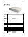
User Manual
ADSL 4-Port Wireless N Router
User Manual
Legal Notice
2009 © All rights reserved. Version 1.0
No part of this document may be reproduced, republished, or retransmitted in any form or by any means whatsoever,
whether electronically or mechanically, including, but not limited to, by way of photocopying, recording, information
recording, or through retrieval systems without the express written permission. We reserve the right to revise this document
at any time without the obligation to notify any person and/or entity. All other company or product names mentioned are
used for identification purposes only and may be trademarks of their respective owners.
LIMITATION OF LIABILITY AND DAMAGES
THE PRODUCT AND THE SOFTWARES WITHIN ARE PROVIDED "AS IS," BASIS. THE MANUFACTURER AND
MANUFACTURER’S RESELLERS (COLLECTIVELY REFERRED TO AS “THE SELLERS”) DISCLAIM ALL WARRANTIES,
EXPRESS, IMPLIED OR STATUTORY, INCLUDING WITHOUT LIMITATION THE IMPLIED WARRANTIES OF NONINFRINGEMENT, MERCHANTABILITY OR FITNESS FOR A PARTICULAR PURPOSE, OR ANY WARRANTIES ARISING
FROM COURSE OF DEALING, COURSE OF PERFORMANCE, OR USAGE OF TRADE. IN NO EVENT WILL THE
SELLERS BE LIABLE FOR DAMAGES OR LOSS, INCLUDING BUT NOT LIMITED TO DIRECT, INDIRECT, SPECIAL
WILLFUL, PUNITIVE, INCIDENTAL, EXEMPLARY, OR CONSEQUENTIAL, DAMAGES, DAMAGES FOR LOSS OF
BUSINESS PROFITS, OR DAMAGES FOR LOSS OF BUSINESS OF ANY CUSTOMER OR ANY THIRD PARTY ARISING
OUT OF THE USE OR THE INABILITY TO USE THE PRODUCT OR THE SOFTWARES, INCLUDING BUT NOT LIMITED
TO THOSE RESULTING FROM DEFECTS IN THE PRODUCT OR SOFTWARE OR DOCUMENTATION, OR LOSS OR
INACCURACY OF DATA OF ANY KIND, WHETHER BASED ON CONTRACT, TORT OR ANY OTHER LEGAL THEORY,
EVEN IF THE PARTIES HAVE BEEN ADVISED OF THE POSSIBILITY OF SUCH DAMAGES. THE ENTIRE RISK AS TO
THE RESULTS AND PERFORMANCE OF THE PRODUCT OR ITS SOFTWARE IS ASSUMED BY CUSTOMER.
BECAUSE SOME STATES DO NOT ALLOW THE EXCLUSION OR LIMITATION OF LIABILITY FOR DAMAGES, THE
ABOVE LIMITATION MAY NOT APPLY TO THE PARTIES. IN NO EVENT WILL THE SELLERS’ TOTAL CUMULATIVE
LIABILITY OF EACH AND EVERY KIND IN RELATION TO THE PRODUCT OR ITS SOFTWARE EXCEED THE AMOUNT
PAID BY CUSTOMER FOR THE PRODUCT.
Page 2 of 61
User Manual
Contents
About the Product.....................................................................................................................................................................6
Requirements............................................................................................................................................................................. 7
Device Design......................................................................................................................................................8
Front Panel ................................................................................................................................. 8
Back Panel ................................................................................................................................. 9
Getting Started.........................................................................................................................................................................10
Check Package Contents............................................................................................................................ 11
Plan Your Network...........................................................................................................................................12
Remove or Disable Conflicts ....................................................................................................................13
Internet Sharing, Proxy, and Security Applications ................................................................ 13
Configuring TCP/IP Settings.................................................................................................... 13
Configuring Internet Properties................................................................................................ 14
Removing Temporary Internet Files........................................................................................ 14
Setup the Device..............................................................................................................................................15
About the Web User Interface......................................................................................................................................... 17
Accessing the Web User Interface ....................................................................................................... 17
Menus............................................................................................................................................................................................ 17
Basic .......................................................................................................................................................................18
Home ........................................................................................................................................ 18
Quick Setup .............................................................................................................................. 18
Advanced.............................................................................................................................................................20
Device Info..........................................................................................................................................................20
Summary .................................................................................................................................. 20
WAN.......................................................................................................................................... 20
Statistics ................................................................................................................................... 21
Route ........................................................................................................................................ 22
ARP........................................................................................................................................... 22
DHCP........................................................................................................................................ 22
Advanced Setup...............................................................................................................................................23
New Connection....................................................................................................................... 23
LAN (Local Area Network)....................................................................................................... 24
NAT........................................................................................................................................... 25
Page 3 of 61
User Manual
Port Triggering.......................................................................................................................... 26
DMZ Host.................................................................................................................................. 27
Security................................................................................................................................................................28
IP Filtering ................................................................................................................................ 28
Parental Control...............................................................................................................................................31
Quality of Service ...........................................................................................................................................33
Queue Config ........................................................................................................................... 33
QoS Classification.................................................................................................................... 34
Routing .................................................................................................................................................................35
Default Gateway....................................................................................................................... 35
Static Route .............................................................................................................................. 35
RIP ............................................................................................................................................ 36
DNS .......................................................................................................................................................................... 37
DNS Server .............................................................................................................................. 37
Dynamic DNS........................................................................................................................... 38
DSL............................................................................................................................................................................41
DNS Proxy Configuration .............................................................................................................................41
Interface Grouping.........................................................................................................................................41
LAN Ports ..............................................................................................................................................................42
IPSec ......................................................................................................................................................................42
Certificate...........................................................................................................................................................42
Print Server ........................................................................................................................................................43
Samba Server ....................................................................................................................................................51
Wireless......................................................................................................................................................................................52
Basic ......................................................................................................................................................................52
Security................................................................................................................................................................53
MAC Filter ............................................................................................................................................................54
Advanced.............................................................................................................................................................54
Station Info.........................................................................................................................................................55
Diagnostics...............................................................................................................................................................................56
Management ............................................................................................................................................................................ 57
Settings................................................................................................................................................................ 57
Backup...................................................................................................................................... 57
Update ...................................................................................................................................... 57
Page 4 of 61
User Manual
Restore Default ........................................................................................................................ 57
System Log ......................................................................................................................................................... 57
TR-069 Client ....................................................................................................................................................58
Internet Time ....................................................................................................................................................58
Access Control.................................................................................................................................................58
Services .................................................................................................................................... 58
Passwords ................................................................................................................................ 58
Update Software..............................................................................................................................................59
Reboot...................................................................................................................................................................59
FCC Notice .................................................................................................................................................................................. 61
Page 5 of 61
User Manual
About the Product
The Wireless 802.11N 4-Port Managed Switch Gateway uses complete solution with wireless onboard
design that fully complies with DSL/ADSL2+ DMT standard. It also provides both hardware and
firmware backward compatible support to ADSL2 and ADSL2+.
Targeted at the residential and Small Office/Home Office users that desires high quality triple play
services, it is the ideal solution to provide a 6 in 1 device for both Wired and Wireless connectivity via a
ADSL/ADSL2+ Ready Modem support, Routing functionality for multi-user sharing, 4 port 10/100
AutoMDI/MDIx Managed Switch for IPTV deployment, high speed 54Mbps IEEE802.11b/g Wireless
LAN Access point with future support to 802.11n standard, and additional USB 2.0 host for attaching
network storage devices (Only supports FAT/FAT32).
Security is provided via a double Stateful Packet Inspection and NAT based firewall. Hardware
accelerated AES/WEP/WPA/WPA2 based encryption/MAC Address Filtering for Wireless links. Multiple
session VPN Pass-through and DMZ support provide additional security support for telecommuters as
well as allow flexibility while maintaining security against malicious hackers. Choices of Dynamic DNS
server give users the flexibility of hosting a web or an FTP server with various domain names.
With Universal Plug and Play support, home networking becomes a breeze for everyone in the family.
Multi Port Range/Popular Application Forwarding makes it even easier to select which application you
want your network to allow while ensuring your security at the same time.
Page 6 of 61
User Manual
Requirements
Minimum requirements include:
•
ADSL Internet Account
•
A computer with:
o Pentium® MMX 233MHz processor
o CD-ROM drive (optional)
o Ethernet card
o Web browser
Page 7 of 61
User Manual
Device Design
Front Panel
Label
POWER
ETHERNET 1-4
USB
WIRELESS
DSL
INTERNET
Action
Description
Off
No power is supplied to the device
Steady green light
Connected to an AC power supply
Steady red light
Error on the device
Off
No Ethernet connection
Steady green light
Ethernet connection has been established
Blinking green light
Transmitting/Receiving data
Off
No USB device connected
Steady green light
USB connection has been established
Blinking green light
Transmitting/Receiving data
Off
Access point is disabled
Steady green light
Access point is enabled
Blinking green light
Transmitting/Receiving data
Off
No DSL line connected
Steady green light
DSL signal has been established
Blinking green light
DSL line is establishing a connection
Off
No Internet connection
Steady green light
Connected to the Internet
Blinking green light
Transmitting/Receiving data
Red
Connection attempt failed
Page 8 of 61
User Manual
Back Panel
Label
Used for…
DSL
Connecting the telephone cable
ETHERNET 1-4
Connecting with computers/devices through Ethernet cable
USB
Connecting a USB devices
RESET
Resetting the device. Press for about 5 seconds to reset.
12V DC
Connecting with the 12V 1.25A power adapter
ON/OFF
Switching the device on/off
Antenna
Connecting the antenna
WPS
Connecting the router with another wireless device that also has a similar WPS (Wi-Fi
Protected Setup) function. The WPS button on the router and in the wireless device is
pressed simultaneously to establish the connection.
Page 9 of 61
User Manual
Getting Started
Setting up the device is easy. The flowchart below provides an outline of the steps you need to go
through. Brief descriptions are included in each step to help you along. More detailed instructions are
provided in the subsequent pages.
Page 10 of 61
User Manual
Check Package Contents
The package contents include:
•
4-port Wireless ADSL Router
•
Easy Start Guide
•
Resource CD
•
AC/DC Power Adaptor
•
Ethernet Cable
•
Telephone Cable
•
POTS Splitter
Page 11 of 61
User Manual
Plan Your Network
Before moving ahead to setup your network, it is a good idea to draw out a network diagram to help
identify the devices and plan out how to connect these devices. The illustration below is an example of
a network diagram.
Each port in the router can be used for different connections. For example:
•
USB – USB printer or Network Storage Drive (Support FAT16/FAT32 Only)
•
Ethernet 1 – Dad’s Computer
•
Ethernet 2 – Mom’s Computer
•
Ethernet 3 – Gaming computer
•
Ethernet 4 – Another router
To create a network diagram:
For wireless devices, identify the wireless devices you want to include in the network
For wired devices, identify which router port you want to use for each device.
Page 12 of 61
User Manual
Remove or Disable Conflicts
To make sure the router installation moves on smoothly, you need to remove or disable conflicts that
may interfere the installation. Probable conflicts may include:
Internet sharing applications
Proxy software
Security software
TCP/IP settings
Internet properties
Temporary Internet files
Internet Sharing, Proxy, and Security Applications
Internet sharing, proxy software, and firewall applications may interfere with the router installation.
These should be removed or disabled before you install and configure the router.
If you have any of the following or similar applications installed on your computer, remove or disable
them according to the manufacturer’s instructions.
Internet Sharing Applications
Proxy Software
Security Software
Microsoft Internet Sharing
WinGate
Symantec
WinProxy
Zone Alarm
Configuring TCP/IP Settings
Use the default TCP/IP settings to allow the router to provide a network address to the computer,
To set the TCP/IP properties:
1. Select Start > Run. This opens the Run dialog box.
2. Enter control ncpa.cpl and then click OK. This opens the Network Connections in your
computer.
3. Right-click LAN and then select Properties. This opens the Local Area Connection Properties
dialog box.
Page 13 of 61
User Manual
4. Select Internet Protocol (TCP/IP) and then click Properties. This opens the Internet Protocol
(TCP/IP) dialog box.
5. Select Obtain an IP address automatically.
6. Click OK to close the Internet Protocol (TCP/IP) dialog box.
7. Click OK to close the Local Area Connection Properties dialog box.
Configuring Internet Properties
To set the Internet Properties:
1. Select Start > Run. This opens the Run dialog box.
2. Enter control inetcpl.cpl and then click OK. This opens the Internet Properties dialog box.
3. Click Connections tab.
4. In the Dial-up and Virtual Private Network settings pane, select Never dial a connection.
5. Click OK to close the Internet Properties dialog box.
Removing Temporary Internet Files
Temporary Internet files are files from Web sites that are stored in your computer. Delete these files to
purge the Internet cache and remove footprints left by the Web pages you visited.
To remove temporary Internet files:
1. Select Start > Run. This opens the Run dialog box.
2. Enter control and then click OK. This opens the Control Panel.
3. Double-click Internet Options. This opens the Internet Options dialog box.
4. In the Temporary Internet Files pane, click Delete Cookies.
5. Click Delete Files.
6. Click OK to close the Internet Properties dialog box.
Page 14 of 61
User Manual
Setup the Device
When installing the router, the common practice is to have the router, the main computer, and phone
jack in the same room. The room should also have enough electrical outlets to match your needs.
To setup the hardware:
1. Plug one end of the Ethernet cable to the router’s ETHERNET port and then plug the other end
to the Ethernet port in your computer.
2. (Optional) If you have another device you need to connect through wire into the router, use
another piece of Ethernet cable. Plug one end of the Ethernet cable from the computer’s
Ethernet port and then plug the other end into an available Ethernet port.
3. Plug one end of the telephone cable from the POTS Splitter’s ADSL port and then plug the
other end into the router’s DSL port
POTS Splitter
A phone line can carry phone call and Internet signals. When you enable the phone line for high
speed Internet, the connection produces high-pitched tones when using the phone. Installing a
Plain Old Telephone Service (POTS) splitter separates the two signals and eliminates the noise.
To setup the telephone POTS Splitter:
Page 15 of 61
User Manual
a. Locate the phone jack in your house.
b. Insert the POTS Splitter into the phone jack.
c. Plug one end of the telephone cable from the POTS Splitter’s TEL port and then plug the other
end into the telephone.
4. Connect the power adapter from the router’s 12V DC port into the electrical outlet.
5. Switch ON.
Page 16 of 61
User Manual
About the Web User Interface
The Web User Interface is used to configure the router settings.
Accessing the Web User Interface
To access the Web User Interface:
1. Open your browser.
2. Enter 192.168.1.1 and then press Enter.
3. Enter the User name and Password, and then click OK.
Default Username and Password is admin.
Menus
The Web User Interface includes the following menus:
Basic
Advanced
Page 17 of 61
User Manual
Basic
Home
Displays the summary and provides an overview of the operating parameters used in your device.
Quick Setup
Quick Setup is a fast and easy way to establish an Internet connection.
Page 18 of 61
User Manual
To use Quick Setup:
1. Open your browser.
2. Enter 192.168.1.1 and then press Enter.
3. Enter the User name and Password, and then click OK. The default User name and Password
is admin.
4. Select Quick Setup.
5. Enter the connection settings
a. Select a Protocol
b. Select an Encapsulation Mode
c. Enter the PPP Username and Password
d. Enter PVC Settings
e. Check Enable Wireless
f.
Enter an SSID
6. Click Save/Reboot.
The router will save your settings and reboot. It will connect to the Internet after the reboot.
When the connection is established, the Internet LED on the router lights or blinks green.
Page 19 of 61
User Manual
Advanced
Advanced Setup provides configuration options for other router functions.
Device Info
Summary
Summary provides an overview of the operating parameters used in your device.
To view Summary:
1. Select Device Info.
2. Click Summary.
WAN
WAN displays a summary of the WAN connection settings.
To view WAN:
1. Select Device Info.
2. Click WAN.
Page 20 of 61
User Manual
Statistics
Statistical information is provided and displayed by LAN, WAN, ATM, and ADSL.
LAN
LAN displays a statistical summary of the data transaction for each interface.
To view LAN statistics:
1. Select Device Info.
2. Click Statistics > LAN.
WAN
LAN displays a statistical summary of the data transaction for each connection.
To view WAN statistics:
1. Select Device Info.
2. Click Statistics > WAN.
ATM
Asynchronous Transfer Mode (ATM) displays a statistical summary of the data transaction for the ATM
interface.
To view ATM statistics:
1. Select Device Info.
2. Click Statistics > ATM.
ADSL
ADSL displays a statistical summary of the ADSL connection.
To view ADSL statistics:
1. Select Device Info.
2. Click Statistics > ADSL.
Page 21 of 61
User Manual
Route
Route displays the routing rules implemented in the router.
To view Route:
1. Select Device Info.
2. Click Route.
ARP
Address Resolution Protocol (ARP) displays the MAC address of each IP device.
To view ARP:
1. Select Device Info.
2. Click ARP.
DHCP
DHCP displays all the DHCP clients connected to the router.
To view DHCP:
1. Select Device Info.
2. Click DHCP.
Page 22 of 61
User Manual
Advanced Setup
New Connection
New Connection allows you to add, edit, or remove WAN service configurations.
To create a new WAN interface configuration:
1. Select Advanced Setup.
2. Click New Connection.
3. Click the Add button.
4. Enter the WAN interface settings:
a. Enter the ATM PVC Configuration, QoS Setting, and then click Next.
b. Enter the WAN service configuration, and then click Next.
c. Enter the PPP settings, and then click Next.
5. Review the summary of your new connection, and click the Apply/Save button.
Page 23 of 61
User Manual
LAN (Local Area Network)
LAN allows you to modify the settings for your local network.
To setup your LAN configuration:
1. Select Advanced Setup.
2. Click LAN.
3. Enter the LAN settings:
a. Enter the IP Address and Subnet Mask you want to specify for your router.
b. Enter the DHCP Server information you want to specify for your LAN.
4. Click the Apply/Save button.
Page 24 of 61
User Manual
NAT
The routers NAT features include Virtual Servers, Port Triggering, and DMZ Host.
Virtual Servers
Virtual Server allows you to direct incoming traffic from the Internet to a specific computer in your local
network. A maximum 32 entries can be configured.
Click Add to create a Virtual Server.
As an example, to setup a web server on a computer using 192.168.1.88 as its IP Address, select
HTTP as Service and enter 192.168.1.88 as the Server IP Address. Otherwise if the service you want
to setup is not available from the Select a Service drop-down list, you can define your own Virtual
Server.
Page 25 of 61
User Manual
Port Triggering
Some applications require that the specific ports in the router’s firewall be opened for access by the
remote parties. A maximum of 32 entries can be configured.
Click Add to setup Port Triggering.
For instance, an application uses port 25 for requests and port 113 for replies. If a computer on the LAN
connects to port 25 on a remote server hosting this application, using Port Triggering on the router,
incoming connections to port 113 (from the remote server) could be redirected to the PC which initiated
the request.
Page 26 of 61
User Manual
DMZ Host
If a computer is assigned as a DMZ Host, it will receive all the data from the Internet that do not belong
to the list of applications configured as a Virtual Server. Enter the LAN IP address of the PC you wish to
set as DMZ Host in the DMZ Host IP Address. If you need to disable the DMZ Host, just clear the DMZ
Host IP Address field, and then click Save/Apply.
Note: DMZ exposes your computer to the Internet and will be vulnerable to malicious attacks.
Page 27 of 61
User Manual
Security
IP Filtering
The router supports IP Filtering, which allows you to easily set up rules to control incoming and
outgoing Internet traffic. The router provides two types of IP filtering: Outgoing IP Filtering and Incoming
IP Filtering.
Outgoing IP Filtering
By default, the router allows all outgoing Internet traffic from the LAN but by setting up Outgoing IP
Filtering rules, you can block some users and/or applications from accessing the Internet.
To create a new outgoing IP filter, click Add. The Add IP Filter-Outgoing page will be displayed.
Key in the following parameters:
Filter Name Key in the name of the filter rule.
Protocol Select the IP protocol to block.
Source IP Address/Subnet Mask Enter the IP address of the PC on the LAN to block.
Page 28 of 61
User Manual
Source Port Enter the port number used by the application to block.
Destination IP Address/Subnet Mask Enter the IP address of the remote server to which
connection should be blocked.
Destination Port Enter the destination port number used by the application to block.
Click Save/Apply to take effect the settings. The new rule will then be displayed in the Outgoing
IP Filtering table list.
To delete the rule, click Remove checkbox next to the selected rule, and click Remove.
Incoming IP Filtering
By default, when NAT is enabled, all incoming IP traffic from WAN is blocked except for responses to
requests from the LAN. However, some incoming traffic from the Internet can be accepted by setting up
Incoming IP Filtering rules.
To create a new incoming IP filter, click Add. The Add IP Filter-Incoming page will be displayed.
Page 29 of 61
User Manual
Key in the following parameters:
Filter Name Key in the name of the filter rule.
Protocol Select the IP protocol to allow.
Source IP Address/Subnet Mask Enter the IP address of the remote server from which to
allow connection.
Source Port Enter the port number used by the application to allow.
Destination IP Address/Subnet Mask Enter the IP address of the PC on the LAN to which
connection is allowed.
Destination Port Enter the destination port number used by the application to allow.
Click Save/Apply to take effect the settings. The new rule will then be displayed in the Incoming
IP Filtering table list.
To delete the rule, click Remove checkbox next to the selected rule, and click Remove.
Page 30 of 61
User Manual
Parental Control
Parental Control allows you to apply router access restrictions among LAN devices within specific times
in a day. A maximum of 16 restriction rules can be created.
To add restrictions, go to Time Restriction and click the Add button. This opens the Access Time
Restriction page. Key in the necessary information and click the Apply/Save button.
To delete a restriction, click Remove checkbox next to the selected restriction, and click Remove.
Key in the following parameters:
User Name Enter a descriptive name for the restriction.
Browser’s MAC Address or Other MAC Address Enter the device MAC Address.
Days of the week Click to select the days on which to apply the restriction.
Start Blocking Time (hh:mm) Enter the time when the restriction will be enabled (00:00 to 23:59).
End Blocking Time (hh:mm) Enter the time when the restriction will be disabled (00:00 to 23:59).
Page 31 of 61
User Manual
To add a URL Filter, go to URL Restriction and click the Add button. This opens the URL Filter page.
Choose URL list type and click the Add button.
Key in the following parameters:
URL Address Enter the URL address of the website you want to add to your list.
Port Number Port number that your web browser will use to access the URL.
NOTE:
Include: URL entered on this list cannot be accessed while all other websites are accessible.
Exclude: URL entered on this list can be accessed while all other websites are not.
Page 32 of 61
User Manual
Quality of Service
QoS gives you the capability to specify the level of quality to be provided for specific applications. By
default, QoS is not enabled.
Queue Config
The screen allows you to configure a QoS queue entry and assign it to a specific network interface.
Each of the queues can be configured for a specific precedence. The queue entry configured here will
be used by the classifier to place ingress packets appropriately.
Note: Lower integer values for precedence imply higher priority for this queue relative to others Click
'Apply/Save' to save and activate the queue.
Click Add to create a QoS Queue Configuration.
Page 33 of 61
User Manual
QoS Classification
You can add or remove QoS Classification rules.
The screen creates a traffic class rule to classify the upstream traffic, assign queue which defines the
precedence and the interface and optionally overwrite the IP header DSCP byte. A rule consists of a
class name and at least one condition below. All of the specified conditions in this classification rule
must be satisfied for the rule to take effect. Click 'Save/Apply' to save and activate the rule.
Click Add to create a Network Traffic Class Rule.
Page 34 of 61
User Manual
Routing
Default Gateway
The Enable Automatic Assigned Default Gateway checkbox is ticked by default. The router will accept
the first received Default Gateway assignment from one of the PPPoA, PPPoE or MER/DHCP enabled
PVC(s).
Static Route
If your LAN consists of multiple subnets and you want to manually define the data transmitting paths,
Static Route is to be used.
To create a new Static Route, click Add. The Routing-Static Route Add page will shows up.
Page 35 of 61
User Manual
The key settings for adding a new Static Route are explained:
Destination Network Address Enter the network address to which the data packets are to be
sent.
Subnet Mask Enter the subnet mask for this destination.
Use Gateway IP Address If you wish to use a specific gateway to reach the destination
network, select this checkbox and then enter the IP address of the gateway.
Use Interface If you wish to use a particular WAN interface, select the checkbox and select the
interface.
Click Save/Apply to take effect the settings.
To delete the entry from the routing table list, click its corresponding Remove button.
RIP
NOTE: RIP CANNOT BE CONFIGURED on the WAN interface that has NAT enabled (such as
PPPoE).
To activate RIP for the WAN Interface, select the desired RIP version and operation and place a check
in the 'Enabled' checkbox. To stop RIP on the WAN Interface, uncheck the 'Enabled' checkbox. Click
the 'Apply/Save' button to start/stop RIP and save the configuration.
Page 36 of 61
User Manual
DNS
DNS Server
DNS (Domain Name System) is an Internet service that translates domain names into IP addresses.
Because domain names are alphabetic, they are easier to remember. However, the Internet is based
on IP addresses. Therefore, each time you type a domain name, a DNS service must translate the
name into the corresponding IP address. For example, the domain name www.example.com might
translate to 198.105.232.4. The DNS system consists of a network of DNS servers. If one DNS server
does not know how to translate a particular domain name, it asks another one and so on until the
correct IP address is returned.
If you select the Enable Automatic Assigned DNS checkbox, the router will receive and use the DNS
Server assigned by your ISP.
To use your preferred DNS servers, disable the Enable Automatic Assigned DNS checkbox and key in
the IP address of your Primary DSN server. Adding a Secondary DNS server is optional.
Page 37 of 61
User Manual
Dynamic DNS
The router offers a Dynamic Domain Name System (DDNS) feature. DDNS lets you assign a fixed host
and domain name to a dynamic Internet IP Address. It is useful when you are hosting your own
website, FTP server, or other server behind the router.
Before using this feature, you need to sign up for DDNS service providers. The router supports these
popular Dynamic DNS service providers:
www.dyndns.org
www.tzo.com
Click Add to create a Dynamic DNS setting.
Page 38 of 61
User Manual
Using DynDNS.org
Key in the following parameters:
D-DNS provider Select DynDNS.org.
Hostname Enter the hostname.
Interface Select an interface.
DynDNS Settings Enter your dyndns.org Username and password.
Page 39 of 61
User Manual
Using TZO
Key in the following parameters:
D-DNS provider Select TZO.
Hostname Enter the hostname.
Interface Select an interface.
TZO Settings Enter your TZO e-mail and key.
Page 40 of 61
User Manual
DSL
The DSL page allows you to select the modulation, the phone line pair and the capability.
DNS Proxy Configuration
The DNS Proxy Configuration page allows you to enable and specify a DNS proxy name.
Interface Grouping
Interface Grouping allows you to create groups composed of the various interfaces available in your
router.
Interface Grouping supports multiple ports to PVC and bridging groups. Each group will perform as an
independent network. To support this feature, you must create mapping groups with appropriate LAN
and WAN interfaces using the Add button. The Remove button will remove the grouping and add the
ungrouped interfaces to the Default group. Only the default group has IP interface.
To create a new interface group:
1. Enter the Group name and the group name must be unique and select either 2. (dynamic) or 3.
(static) below:
2. If you like to automatically add LAN clients to a WAN Interface in the new group add the DHCP
vendor ID string. By configuring a DHCP vendor ID string any DHCP client request with the
specified vendor ID (DHCP option 60) will be denied an IP address from the local DHCP
server.
3. Select interfaces from the available interface list and add it to the grouped interface list using
the arrow buttons to create the required mapping of the ports. Note that these clients may
obtain public IP addresses
4. Click Save/Apply button to make the changes effective immediately
IMPORTANT: If a vendor ID is configured for a specific client device please REBOOT the client device
attached to the modem to allow it to obtain an appropriate IP address.
Page 41 of 61
User Manual
LAN Ports
LAN Ports allow you to enable/disable the virtual LAN ports feature on your router.
IPSec
Your router supports the authentication and encryption of data packets.
Certificate
Certificates are used to verify the identity of you and your peers. You can either create or import a
Certificate Request.
Page 42 of 61
User Manual
Print Server
The DSL1015EN(L) is equipped with a USB Host print server on board. To use the print server on the
DSL1015EN(L), you need to accomplish the following tasks:
1. Install the printer drivers on the computer
2. Enable the DSL1015EN(L) for Print Server
3. Add a network printer
INSTALL THE PRINTER DRIVERS
Printers using the USB port come with a software installation CD for installing the printer drivers and
applications. The drivers for the printers must be installed on the computer first to prepare it to use the
printer when it’s connected to the DSL1015EN(L). Refer to the printer’s documentation on how to install
the drivers.
ENABLE THE PRINT SERVER APPLICATION
1. Open your Internet browser and log on to http://192.168.1.1, on the authentication page, type
admin for both the username and password.
2. Click on Advanced Setup and click on Print Server.
3. Click on Enable on-board print server.
4. Input the Printer Name and Printer Make and Model on the fields.
5. To commit and save the changes, click on Save/Apply button.
Page 43 of 61
User Manual
CONNECTING THE PRINTER
1. Turn OFF the DSL1015EN(L).
2.
Connect the Printer on the USB port and switch it ON.
ADD A NETWORK PRINTER
FOR WINDOWS XP
1. Before you continue, ensure that you’ve installed the printer drivers on this computer and the
printer is attached to the DSL1015EN(L).
2. Click on the Start Button > Control Panel > Printers and Other Hardware > Printers and
Faxes.
Page 44 of 61
User Manual
3. Click on Add a Printer.
4. Click on Next on the Add Printer Wizard page.
5. Choose A network printer, or a printer attached to another computer and click Next, on the
Local or Network Printer page.
6. Choose Connect to a printer on the Internet or on a home or office network:, on the
Specify a Printer page.
Page 45 of 61
User Manual
This is the printer name that you've set earlier
http://192.168.1.1:631/printers/PrinterBrotxx
7. On the URL field, input the following and click Next.
8. Once the computer detects the printer on the Print Server, it will ask for the printer
manufacturer and model, a list of printers will be shown, select your printer from the list and
click OK.
9.
Click Finish, on the Completing the Add Printer Wizard page.
Page 46 of 61
User Manual
PRINTING A TEST PAGE AFTER INSTALLATION
1. Open the Printers and Faxes page from Control Panel.
2. Right click on the new printer and click on Properties.
3.
Click on the Print Test Page button on the Printer properties page, the test page will be printed
on the network printer.
FOR WINDOWS VISTA
1. Click on the Start Button> Control Panel.
2. Click Printer under the Hardware and Sound category.
3. Click on Add a Printer.
Page 47 of 61
User Manual
4. Click on Add a network, wireless or Bluetooth printer.
5. Click on Stop on Searching for available printers… page.
6. Click on The printer that I want isn’t listed.
Page 48 of 61
User Manual
7. Click on Select a shared printer by name on the Find a printer by name on TCP/IP
address, and input the following URL on the field and click on Next.
This is the printer name that you've set earlier
http://192.168.1.1:631/printers/PrinterBrotxx
8. Once the computer detects the printer on the Print Server, it will ask for the printer
manufacturer and model, a list of printers will be shown, select your printer from the list and
click OK.
Page 49 of 61
User Manual
9. Click Next on the Type a Printer Name page.
10.
To print a test page click on Print a test page on the confirmation screen, click Finish to
complete the installation.
Notes:
1.
USB Printers that supports IPP – Internet Printing Protocol are that only printers that will work with the Print Server
application on the DSL1015EN(L). Consult the printer manufacturer for more information on your printer.
2.
Scanning, Faxing and Photocopying functions on Multifunction printers are currently not supported on the
DSL1015EN(L), Print function is the only feature that will work on these printers type when connected to the
DSL1015EN(L).
3. Refrain from connecting a USB Hub on the USB port on the DSL1015EN(L).
Page 50 of 61
User Manual
Samba Server
The USB port on the DSL1015EN(L) is capable of sharing the contents of your USB storage device to
the network. The following steps should be accomplished to share your files on the network.
USING THE USB PORT WITH USB STORAGE DEVICES
1. Ensure that the DSL1015EN(L) is OFF, connect the USB storage device and switch it ON.
2. Once the DSL1015EN(L) is ready, you can access the files from your windows explorer, this
can be done by clicking on the Start Button> Run.
3. On the Open box, type: \\192.168.1.1 and click on OK. If there is a prompt for a username and
password, type admin for both the username and password.
4. From windows explorer, you will see a folder called sda1, this is the folder containing the files
from your USB storage device.
SAFELY REMOVING THE USB STORAGE DEVICE FROM THE DSL1015EN
1. Open you Internet browser and log on to http://192.168.1.1, on the authentication page, type
admin for both the username and password.
2. Click on USB Device under Advanced and click on the Umount button from the USB
Information page.
3. You can safely remove the device once you see the Mount button displayed on the table for
USB Information.
Note:
The USB Storage feature on the DSL1015EN(L) can only support devices that are formatted with FAT/FAT32 file systems.
NTFS and other file systems are currently not supported.
Page 51 of 61
User Manual
Wireless
Basic
The Wireless Basic page allows you to enable the wireless network and configure its basic settings.
To configure basic wireless settings:
1. Click Wireless.
2. Select Basic.
3. Select Enable Wireless.
4. Select Hide Access Point if you do not want the SSID to be seen.
5. Enter preferred SSID.
6. Select a country.
7.
Click Save/Apply.
Page 52 of 61
User Manual
Security
The router supports all the popular wireless security protocols.
These include:
•
Open System Authentication
•
WEP-Shared
•
WPA-PSK
•
WPA2-PSK
•
Mixed WPA2/WPA - PSK
Open System Authentication
- Means your wireless network does not require a security key to connect.
Page 53 of 61
User Manual
MAC Filter
MAC Filter allows you to add or remove the MAC Address of devices that will be allowed or denied
access to the wireless network.
Click Add to add a MAC Address.
Advanced
Advanced Wireless allows you to configure detailed wireless settings.
Page 54 of 61
User Manual
Station Info
Station Info scans wireless stations and displays their status.
Page 55 of 61
User Manual
Diagnostics
The router has a diagnostic feature to test your DSL connection. You can use the diagnostic menu to
perform the following test functions from the router.
Testing the connection to your local network
Testing the connection to your DSL service provider.
Testing the connection to your Internet service provider.
Page 56 of 61
User Manual
Management
Settings
When it comes to managing the settings that you have executed to the router, you can choose to:
Backup the settings as a configuration file stored onto your PC
Update the current settings from a previously saved configuration file
Erase the current settings and restore the default factory values
Backup
To backup the settings as a configuration file saved on your PC, click Backup Settings.
Select the folder where you want to save the file and key in the file name under which you want to save
the settings.
Update
To import a previously saved configuration file from your PC and update the settings of your router,
click Browse to locate the binary (.BIN or .IMG) upgrade file. Then click Update Settings.
Restore Default
To restore your router to its factory default settings, click Restore Default Settings. When prompted,
click OK.
Upon clicking OK, you will be prompted to follow the instruction as shown below.
System Log
This feature provides you a comprehensive list of log entries reporting events which you have
configured for viewing.
To view the log, click View System Log.
Page 57 of 61
User Manual
TR-069 Client
As a TR-069 capable router, the Internet service provider can remotely update the settings of the
device.
Internet Time
Enable Internet Time to automatically synchronize your time with a time server.
Access Control
This feature enables you manage the user access rights for remote access management based on the
Services being used, IP addresses and Passwords.
Services
Select which Services to allow and whether to allow from the LAN or the WAN.
Passwords
When you configure the router through an Internet browser, the system requires you to enter your user
name and password to validate your access permission. By default, the Username is set to “admin” and
the Password to “admin”.
The user name "admin" has unrestricted access to change and view configuration of your DSL Router.
The user name "support" is used to allow an ISP technician to access your DSL Router for
maintenance and to run diagnostics.
The user name "user" can access the DSL Router, view configuration settings and statistics, as well as,
update the router's software.
Use the fields to enter up to 16 characters and click "Apply" to change or create passwords.
Note: Password cannot contain a space.
Page 58 of 61
User Manual
Update Software
The router’s software is stored in the FLASH memory and can be upgraded as new software is
released. Click Browse to locate the software file and then click Update Software.
To update the router’s firmware:
1. Obtain an updated software image file from your ISP.
2. Enter the path to the image file location in the box below or click the "Browse" button to locate
the image file.
3. Click the "Update Software" button once to upload the new image file.
NOTE: The update process takes about 2 minutes to complete, and your DSL Router will reboot.
Reboot
This feature allows the router to enable new network configuration to take effect or to clear problems
with the modem router’s network connection.
Page 59 of 61
User Manual
Safety Precautions
Do not open, service, or change any component.
Only qualified technical specialists are allowed to service the equipment.
Observe safety precautions to avoid electric shock
Check voltage before connecting to the power supply. Connecting to the wrong voltage will
damage the equipment.
Page 60 of 61
User Manual
FCC Notice
This equipment has been tested and found to comply with the limits for a Class B digital device, pursuant to Part 15 of the
FCC Rules. These limits are designed to provide reasonable protection against harmful interference in a residential
installation. This equipment generates, uses, and can radiate radio frequency energy and, if not installed and used in
accordance with the instructions, may cause harmful interference to radio communications. However, there is no guarantee
that interference will not occur in a particular installation. If this equipment does cause harmful interference to radio or
television reception, which can be determined by turning the equipment off and on, the user is encouraged to try to correct
the interference by one or more of the following measures:
•
Reorient or relocate the receiving antenna.
•
Increase the separation between the equipment and receiver.
•
Connect the equipment into an outlet on a circuit different from that to which the receiver is connected.
•
Consult the dealer or an experienced radio or television technician for help.
Modifications
The FCC requires the user to be notified that any changes or modifications made to this device that are not expressly
approved by Aztech could void the user’s authority to operate the equipment.
This device complies with Part 15 of the FCC rules.
This device complies with Part 15 of the FCC rules. Operation is subject to the following two conditions:
1.
This device may not cause harmful interference, and
2.
This device must accept any interference received, including interference that may cause undesired operation.
Exposure Information to Radio Frequency Energy
This equipment complies with FCC radiation exposure limits set forth for an uncontrolled environment. This equipment
should be installed and operated with minimum distance of 20 cm between the radiator and your body.
Page 61 of 61