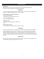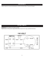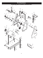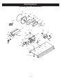
1
1”x42” Belt / 8” Disc Sander
Owner’s Manual
Model: 50-142
Record the serial number and date of purchase
in your manual for future reference.
Serial number:
Date of purchase:
For more information:
www.rikontools.com or [email protected]
For Parts or Questions:
[email protected] or 877-884-5167
Part # 50-142M1
Safety Warning
IMPORTANT! Safety is the single most important consideration in the operation of this equipment. The following
instructions must be followed at all times.
There are certain applications for which this tool was designed. We strongly recommend that this tool not be modified and/
or used for any other application other than that for which it was designed. If you have any questions about its application,
do not use the tool until you have contacted us and we have advised you.
General Safety Warnings
KNOW YOUR POWER TOOL. Read the owner’s manual carefully. Learn the tool’s applications, work
capabilities, and its specific potential hazards.
ALWAYS GROUND ALL TOOLS.
If your tool is equipped with a three-pronged plug, you must plug it into a three-hole electric receptacle.
If you use an adapter to accommodate a two-pronged receptacle, you must attach the adapter plug to a
known ground. Never remove the third prong of the plug.
ALWAYS AVOID DANGEROUS ENVIRONMENTS.
Never use power tools in damp or wet locations. Keep your work area well lighted and clear of clutter.
ALWAYS REMOVE THE ADJUSTING KEYS AND WRENCHES FROM TOOLS AFTER USE.
Form the habit of checking to see that keys and adjusting wrenches are removed from the tool before
turning it on.
ALWAYS KEEP YOUR WORK AREA CLEAN. Cluttered areas and benches invite accidents.
ALWAYS KEEP VISITORS AWAY FROM RUNNING MACHINES.
All visitors should be kept a safe distance from the work area.
ALWAYS MAKE THE WORKSHOP CHILDPROOF.
Childproof with padlocks, master switches, or by removing starter keys.
NEVER OPERATE A TOOL WHILE UNDER THE INFLUENCE OF DRUGS,
MEDICATION, OR ALCOHOL.
ALWAYS WEAR PROPER APPAREL.
Never wear loose clothing or jewelry that might get caught in moving parts. Rubber-soled footwear is
recommended for the best footing.
ALWAYS USE SAFETY GLASSES AND WEAR HEARING PROTECTION.
Also use a face or dust mask if the cutting operation is dusty.
NEVER OVERREACH.
Keep your proper footing and balance at all times.
NEVER STAND ON TOOLS.
Serious injury could occur if the tool is tipped or if the cutting tool is accidentally
2
ALWAYS DISCONNECT TOOLS.
Disconnect tools before servicing and when changing accessories such as blades, bits, and cutters.
ALWAYS AVOID ACCIDENTAL STARTING.
Make sure switch is in “OFF” position before plugging in cord.
NEVER LEAVE TOOLS RUNNING UNATTENDED.
ALWAYS CHECK FOR DAMAGED PARTS.
Before initial or continual use of the tool, a guard or other part that is damaged should be checked to
assure that it will operate properly and perform its intended function. Check for alignment of moving
parts, binding of moving parts, breakage of parts, mounting, and any other conditions that may affect its
operation. A guard or other damaged parts should immediately be properly repaired or replaced.
Special Safety Rules For Sanders
1.Do not operate this machine until you have read all of the following instructions.
2.Do not attempt to operate this machine until it is completely assembled.
3. Do not turn ON this machine if any pieces are missing.
4. If you are not familiar with the operation of the machine, obtain assistance from a qualified
person.
5.It is highly recommended that this machine be placed on a level surface.
6.Always wear protective eyewear prior to operating this machine.
7.Do not operate this machine if you are under the influence of drugs and/or alcohol.
8.Remove all jewelry prior to operating this machine.
9.Do not wear any gloves while operating this machine.
10.Always make sure the power switch is in the OFF position prior to plugging in the machine.
11.Always make sure the power switch is in the OFF position when doing any assembly or setup
operation.
12.Always wear a dust mask when cleaning or working near a sander.
13.The use of any accessories or attachments not recommended may cause injury to you and
damage your machine.
14.This machine must be properly grounded.
15.Always keep your face and hands clear of moving parts such as sanding belts and discs.
16.Keep these instructions for future reference.
California Proposition 65 Warning
WARNING: Some dust created by power sanding, sawing, grinding, drilling, and other construction activities contains
chemicals known to the State of California to cause cancer and birth defects or other reproductive harm.Your risk from
exposure to these chemicals varies, depending on how often you do this type of work. To reduce your exposure, work in
a well-ventilated area and with approved safety equipment, such as dust masks that are specially designed to filter out
microscopic particles.
For more detailed information about California Propostion 65 log onto rikontools.com.
SAVE THESE INSTRUCTIONS.
Refer to them often.
3
Table of Contents
Safety Warnings......................................................................................................................................2-3
Safety Rules for Sanders............................................................................................................................... 3
Specifications.........................................................................................................................................................4
Unpacking and Contents..................................................................................................................................... .5
Getting to Know Your Sander..........................................................................................................................6
Assembly................................................................................................................................................................ 6-10
Operations......................................................................................................................................11-13
Adjustments.........................................................................................................................................................14
Maintenance..........................................................................................................................................................15-16
Wiring Diagram......................................................................................................................................16
Electrical Requirements...................................................................................................................................17
Explosion Diagram..............................................................................................................................................18-19
Parts List...............................................................................................................................................................20-21
Warranty.................................................................................................................................................................22
Notes....................................................................................................................................23
Specifications
Model Number
Belt Size
Belt Speed
Disc Size
Disc Speed
Hose Inlet
Motor HP
Motor Volts/Amps
Net Weight
50-142
1” x 42”
3,000 FPM
8”
1,725 RPM
2”
1/3HP
110V/4A
58.5lbs
4
Contents of Package
Unpacking and Checking Contents
Unpack your sander from its carton and check to see that you have all of the following items. Do not
turn your sander ON if any of these items are missing. You may cause injury to yourself or damage to
your machine.
A
C
B
D
E
A. Motor and Base
B. Belt Housing Assembly
C. Disc Table
D. Belt Table
E. Motor Belt Cover
F. Sanding Disc, 8”
G
H
J
I
L
M
G. V-Belt Rear Cover
H. Dust Port, 2”
I. Disc Dust Cover
J. Miter Gauge
K. Table Lock Handles
L. Hex Wrench 2.5MM
M. Hex Wrench 8MM
5
K
F
Getting to Know Your Sander
B
A
F
C
D
E
G
P
O
N
M
L
K
Item
Description
Item
A.
B.
C.
D.
E.
F.
G.
H.
Sanding Belt 1” x 42”
Sanding Belt Tracking Knob
Sanding Disc 8”
Miter Gauge
Disc Table
V-Belt Safety Cover
Sanding Belt Safety Cover
Sanding Belt Dust Port
I.
J.
K.
L.
M.
N.
O.
P.
H
J
I
Description
Motor
Disc Table Angle Scale
Disc Table Lock Handle
Disc Dust Port
ON/OFF Switch with Disabling Key
Rubber Machine Feet
Sanding Belt Table Lock Handle
Sanding Belt Table
Assembly
The sander must not be plugged in and the power switch must be in the OFF position
until assembly is complete.
Unpacking and Clean-up
1. Carefully finish removing all contents from shipping carton. Compare contents of the
shipping carton with the list of contents above. Place parts on a protected surface.
2. Report any shipping damage to your local distributor.
3. Clean all rust protected surfaces. Do not use; gasoline, paint thinner, mineral spirits,
etc. These may damage painted surfaces.
4. Set packing material and shipping carton to the side. Do not discard until machine
has been set up and is running properly.
6
Assembly
To assemble your 50-142 sander:
1. Using 13mm wrenches, loosen the four motor
mount hex bolts (Figure 6) so you can adjust the
motor position in the next steps.
2. With assistance, position the belt housing assembly on the left side of the base, taking care
not to pinch the power cords between the assembly and the base.
Motor Mounting
Hex Bolts 2 of 4
Fig. 06
3. Place the V-belt around both pulleys, and
secure the belt housing assembly with the two
M10-1.5 x 20 cap screws, lock washers, and flat
washers (see Figures 7 & 8)—do not fully tighten
the fasteners for now.
4. Center the motor arbor in the cutout of the cast
iron disc guard (see Figure 9), then re-tighten the
motor mount hex bolts.
Fig.07
Belt Housing
Assembly
5. Position the belt housing assembly so there
is about 1⁄4" V-belt deflection when moderate
pressure is applied to the V-belt between the pulleys (see Figure 10)—then fully tighten the cap
screws to secure the belt housing assembly in
place.
Base
Fig.08
6. Insert one M4-.7 x 10 Phillips head screw and
flat washer into the left inside mounting bracket
of the V-belt safety cover (see Figure 11). Then
hold it in place with a screwdriver as you slide
the cover over the V-belt and tighten the fastener
into the cast iron disc guard.
Set Screw
Access Hole
7. Secure the right side of the V-belt cover with
one M4-.7 x 10 Phillips head screw and flat
washer.
Fig. 09
Pulley
8. Position the V-belt rear cover, as shown in
Figure 12, and secure it in place with the
M4-.7 x 40 Phillips head screw and wingnut.
Deflection
9. Slide the aluminum disc onto the motor arbor,
making sure to align the arbor key with the disc
keyway.
Pulley
Fig. 10
7
Assembly
10. Rotate the disc until you can see the set
screw through the hole on the back of the V-belt
safety cover (see Figure 13)
11. Using the 2.5mm hex wrench, tighten the set
screw to secure the disc to the motor arbor.
Fig.11
12. Install the disc dust cover, as shown in
Figure 14, with three M4-.7 x 10 Phillips head
screws and flat washers.
Wing Nut
13. Lay the sander down on a flat surface, as
shown in Figure 15, and place a thin piece of
cardboard approximately 1⁄16” thick over the
sanding disc. This piece of carboard will act as a
spacer when you install the disc table.
V-Belt
Fig.12
14. Keeping the cardboard in place, align the
half-arc key of the disc table with the indented
keyway on the disc guard (see the inset of Figure 16). Then secure the table with a table lock
handle, and remove the cardboard.
Set Screw
Access Hole
Fig.13
15. Secure the dust port, as shown in Figure
17, with the M6-1 x 15 Phillips head screw and
flatwasher.
Mounting Screws
16. Square the disc table to the sanding disc
(refer to Squaring Disc Table on Page 14).
Fig.14
17. Using the M4-.7 x 10 Phillips head screw,
align the red scale pointer with the “0” mark on
the table angle scale (see Figure 18).
Cardboard
18. Install the belt table with a 1⁄16” clearance
from the sanding belt, and secure it in place with
the table lock handle (see Figure 19).
Fig.15
19. Loosen the cap screw shown in Figure 20,
adjust the belt support approximately 1⁄16” away
from the sanding belt, then re-tighten the cap
screw.
Keyway
Key
Table Lock
Fig.16
8
Assembly
Test Run After Assembly
Once the assembly is complete, test run your
sander to make sure it runs properly and is
ready for regular operation.
If you have questions regarding assmbly before operating the sander, contact RIKON Tech
Support at 877-884-5167 for assistance.
Mounting
Screw
Fig.17
To test run the sander:
1. Make sure you have read the safety
instructions at the beginning of the manual
and that the machine is setup properly.
Pointer
2. Make sure all tools and objects used duringsetup are cleared away from the machine.
3. Connect the machine to the power source.
Fig.18
4. Verify that the machine is operating correctly
by turning the machine ON.
—When operating correctly, the machine
runs smoothly with little or no vibration or
rubbing noises.
— Investigate and correct strange or unusual
noises or vibrations before operating the machine further. Always disconnect the machine
from power when investigating or correcting
potential problems.
Fig.19
5. Turn the machine OFF.
Belt
Support
6. Remove the switch disabling key, as shown
in Figure 21.
Cap
Screw
7. Flip the toggle switch to the ON position.
This will ensure that the safety function is
working properly.
Fig.20
8. When the Test Run has been successfully
completed, check the tracking of the sanding
belt and make adjustments if necessary (refer
to Sanding Belt Tracking on Page 12).
Fig.21
9
Assembly
Mounting Sander
Once you have confirmed that your machine is
running properly, mount it to a workbench. The
strongest mounting option is a "Through Mount"
where holes are drilled all the way through the
workbench, and hex bolts, washers, and lock
nuts are used to secure the sander to the workbench. Another option for mounting is a “Direct
Mount” where the machine is simply secured to
the workbench with a lag screw.
Note: To reduce vibration when operating, keep
the rubber cushion included with your sander
between the machine base and the workbench.
Fig.22
Dust Collection
To connect a dust collection hose:
1. Install a 2” dust hose from a dust collection
system over each dust port, and secure them in
place with a 2” hose clamp.
2. Tug the hoses to make sure they do not
come off.
CAUTION
DO NOT operate this sander without
an adequate dust collection system. This
sander creates substantial amounts of wood
dust while operating. Failure to use a dust collection system can result in short and long-term
respiratory illness.
Fig.23
California Proposition 65 Warning
WARNING: Some dust created by power sanding, sawing, grinding, drilling, and other construction activities contains
chemicals known to the State of California to cause cancer and birth defects or other reproductive harm.Your risk from
exposure to these chemicals varies, depending on how often you do this type of work. To reduce your exposure, work in
a well-ventilated area and with approved safety equipment, such as dust masks that are specially designed to filter out
microscopic particles.
For more detailed information about California Propostion 65 log onto rikontools.com.
10
Operations
Disc Sanding
CAUTION
Always keep the workpiece on the left side of the
wheel that rotates down toward the table. This will
keep the workpiece from flying out of your hands
due to kickback.
Fig.24
To use the sanding disc:
1. DISCONNECT THE SANDER FROM
POWER!
2. Adjust the angles of the disc sanding table and
the miter gauge for your operation.
3. Connect the sander to power, turn it ON, and
allow it to reach full speed.
4. Place the workpiece on the table and firmly
Fig.25
5. Slowly, and with light pressure, move the workpiece into the left side of the sanding disc. See
Figures 24 thru 26 for examples of disc sanding.
Note: To prevent burning the workpiece and
overloading the sanding disc, move the workpiece
slowly back and forth from the left side of the
sanding disc to the center.
Fig.26
11
Operations
Belt Sanding
Use the sanding belt for the long, flat surfaces
of the workpiece.
NOTICE:
To avoid the risk of kickback and personal
injury, always keep the workpiece firmly on
the table, and never sand the short side of
the workpiece with the sanding belt.
To use the sanding belt:
1. DISCONNECT THE SANDER FROM
POWER!
Fig.27
2. Using a protractor or other angle measuring
tool, set the correct angle of the sanding belt
table for your operation.
3. Connect the sander to power, turn it ON, and
allow it to reach full speed.
4. Place the workpiece on the sanding belt
table, then slowly, and with light pressure, move
the workpiece into the sanding belt.
Note: Hold the workpiece firmly on the table,
but keep your fingers away from the sanding
surface, as shown in Figure 27.
Tracking
Adjustment
Knob
Sanding Belt Tracking
The sanding belt must track in the center of the
top pulley to avoid damaging itself during use.
To adjust the sanding belt tracking:
1. Turn the sander ON.
Top Pulley
2. Observe the sanding belt as it moves over
the top pulley (see Figure 28).
Fig.28
3. Slowly adjust the tracking adjustment knob
until the sanding belt tracks in the center of the
top pulley.
12
Operations
Changing the Sanding Belt
Sanding
Belt
Direction
Most sanding belts are designed to sand in only
one direction and will have a direction arrow on the
back of the belt. The 50-142 is designed so that the
sanding belt travels downward to the sanding table.
To change the sanding belt:
1. DISCONNECT THE SANDER FROM
POWER!
2. Unscrew the two knobs from the sanding belt
cover and remove the cover from the sander (see
Figure 29).
3. Press down firmly on the tracking adjustment
knob to remove the tension from the sanding belt.
4. Roll the old sanding belt off the three pulleys,
and roll the new belt back on.
Fig.29
5. Make sure the sanding belt is positioned in the
center of all three pulleys.
6. Replace and secure the sanding belt cover.
7. Check and the adjust the sanding belt traction,
as instructed on Page 12.
Changing the
Sandpaper Disc
The Model 50-142 accepts 8" diameter pressure
sensitive adhesive (PSA) sandpaper discs.
To change the sanding disc:
1. DISCONNECT THE SANDER FROM
POWER!
Set Screw
Access Hole
2. Remove the sanding disc table, disc dust
port, and dust cover.
Fig.30
3. Rotate the disc until you can see the set
screw through the access hole (see Figure
30).
4. Using the 2.5mm hex wrench through the
access hole in the V-belt safety cover, loosen the
set screw and remove the sanding disc.
13
5. Peel off the old sandpaper disc, clean
the aluminum disc thoroughly, and apply
the new sandpaper disc.
6. Reverse Steps 2–4 to reassemble your
sander.
Adjustments
Squaring Disc Table
To square the sanding disc table:
1. DISCONNECT THE SANDER FROM
POWER!
2. Place a machinist's square or other 90°
measuring tool against the disc table and
sanding disc (see Figure 31).
3. Loosen the table lock handle, adjust the table
square with the sanding disc, then re-tighten the
table lock handle.
Fig.31
4. Loosen the Phillips head screw on the angle
pointer, position the red scale pointer over the
"0" mark on the angle scale, then retighten
the screw.
Tensioning/Replacing V-Belt
To adjust the V-belt tension:
1. DISCONNECT THE SANDER FROM
POWER!
2. Remove the disc table, dust port, dust
cover, and V-belt safety cover.
3. Lay the sander on its back, and loosen (but
do not remove) the two cap screws securing
the belt housing assembly.
Fig.32
4. Position the belt housing assembly so there
is about 1⁄4" V-belt deflection when moderate
pressure is applied to the V-belt between the
pulleys (see Figure 10 on Page 14)—then
fully tighten the cap screws to secure the belt
housing assembly in place.
Belt Housing
Assembly
5. Check the V-belt tension and re-adjust if
necessary.
Base
6. Re-install the V-belt safety cover, dust cover,
dust port, and disc table.
Fig.33
7. Use same procedure to replace the belt if
worn.
14
Maintenance
WARNING
Always disconnect power to the machine before performing maintenance.
Failure to do this may result in serious personal injury.
Schedule
For optimum performance from your machine, follow this maintenance schedule and
refer to any specific instructions given in this section.
Before Each Use, Check and Correct:
• Loose mounting bolts.
• Damaged or worn sanding belt or disc.
• Worn or damaged wires.
• Any other unsafe condition.
After Each Use:
• Clean/vacuum dust buildup on tables and
motor.
After 50 Hours of Use:
• Check and correct V-belt tension, damage, or wear.
Cleaning
Cleaning the Model 50-142 is relatively easy. Vacuum excess sawdust, and wipe off
the remaining dust with a dry cloth. Avoid the use of compressed air near bearings.
Wiping the table clean after every use ensures moisture from wood dust does not
remain on bare metal surfaces. If any resin has built up, use a resin dissolving cleaner
to remove it. After cleaning, treat all unpainted cast iron and steel with a non-staining
lubricant.
Lubrication
All bearings are sealed and permanently lubricated. Avoid the use of compressed air
near bearings. Simply wipe clean with a dry cloth.
15
Maintenance
Use this section to record maintenance, service and any calls to Technical Support:
Wiring Diagram
WARNING:This machine must be grounded.
Replacement of the power supply cable should only be done by a qualified electrician.
16
Electrical Requirements
In the event of a malfunction or breakdown, grounding provides a path of least resistance for electric
current to reduce the risk of electric shock. This tool is equipped with an electric cord having an
equipment-grounding conductor and a grounding plug. The plug must be plugged into a matching
outlet that is properly installed and grounded in accordance with all local codes and ordinances.
Do not modify the plug provided. If it will not fit the outlet, have the proper outlet installed by a
qualified electrician.
Improper connection of the equipment-grounding conductor can result in a risk of electric shock. The
conductor, with insulation having an outer surface that is green with or without yellow stripes, is the
equipment-grounding conductor. If repair or replacement of the electric cord or plug is necessary, do
not connect the equipment-grounding conductor to a live terminal.
Check with a qualified electrician or service personnel if the grounding instructions are not completely
understood, or if in doubt as to whether the tool is properly grounded.
Use only three wire extension cords that have three-prong grounding plugs and three-pole
receptacles that accept the tool’s plug.*
Repair or replace a damaged or worn cord immediately.
This tool is intended for use on a circuit that has an outlet that looks the one illustrated in Figure
A below. The tool has a grounding plug that looks like the grounding plug as illustrated in Figure A
below. A temporary adapter, which locks like the adapter as illustrated in Figure B below, may be
used to connect this plug to a two-pole receptacle, as shown in Figure B if a properly grounded outlet
is not available.** The temporary adapter should only be used until a properly grounded outlet can
be installed by a qualified electrician. The green colored rigid ear or tab, extending from the adapter,
must be connected to a permanent ground such as a properly grounded outlet box.
* Canadian electrical codes require extension cords to be certified SJT type or better.
** Use of an adapter in Canada is not acceptable.
17
Parts Explosion
Sanding Belt & Motor Breakdown
5
6
2
7
3
22
23
8
1
9
24
25
4
12
13
26
18
10
28
11
16
46
27
14
15
45
29
47
30
17
19
33
51
34
21
53
36
49
50
32
20
48
35
37
52
38
39
54
55
56
56-2
57
58
41
56-1
59
62
64
63
43
65
66
61
67
80
68
60
70
71
69
72
18
81
Parts Explosion
Sanding Disc Breakdown
99
100
102
104
101
105
106
110
107
108
109
120
131
123
121
139
130
124
125
137
63
132
141
140
122
47
143
127
128
129
136
133
134
61
60
19
135
58
144
142
Parts List
Part No.
50-142-1
50-142-2
50-142-3
50-142-4
50-142-5
50-142-6
50-142-7
50-142-8
50-142-9
50-142-10
50-142-11
50-142-12
50-142-13
50-142-14
50-142-15
50-142-16
50-142-17
50-142-18
50-142-19
50-142-20
50-142-21
50-142-22
50-142-23
50-142-24
50-142-25
50-142-26
Part No.
Description
Hex Soc Screw M10×40
Flat Washer 10mm
Spring
Spacer
Track Screw
Spring
Support
Pin 3×20
Shaft
Shaft
Screw M5×8
Screw M5×10
Drive Pulley
Retaining Plate
Screw M4×8
Washer 4mm
Ball Bearing 6202ZZ
Key C5×25
Shaft
Ball Bearing 6002ZZ
Frame
Ball Bearing
Drive Wheel
Flat Washer 6mm
Lock Washer 6mm
Screw M6×10
50-142-27
50-142-28
50-142-29
50-142-30
50-142-32
50-142-33
50-142-34
50-142-35
50-142-36
50-142-37
50-142-38
50-142-39
50-142-41
50-142-43
50-142-45
50-142-46
50-142-47
50-142-48
50-142-49
50-142-50
50-142-51
50-142-52
50-142-53
50-142-54
50-142-55
50-142-56
20
Description
Screw M10×15
Lock Washer 10mm
Flat Washer 10mm
Platen
Ball Bearing 6202ZZ
Drive Wheel
Retaining Ring 15mm
Screw M5×12
Drive Wheel
Sanding Belt 1” ×42”
Nut M6
Screw M6×45
Knob
Cover
Table
Screw M5×20
Clamp Assem
Flat Washer 10mm
Belt Table Bracket
Flat Washer 10mm
Lock Washer 10mm
Screw M8×16
Screw M5×10
Drive Pulley
Key C5×55
Motor 1/3HP 110V 1PH
Parts List
Part No.
50-142-57
50-142-58
50-142-59
50-142-60
50-142-61
50-142-62
50-142-63
50-142-64
50-142-65
50-142-66
50-142-67
50-142-68
50-142-69
50-142-70
50-142-71
50-142-72
50-142-80
50-142-81
50-142-99
50-142-100
50-142-101
50-142-102
50-142-104
50-142-105
50-142-106
50-142-107
Part No.
Description
Nut M8
Lock Washer 8mm
Flat Washer 8mm
Screw M8×25
Base
Screw M4×8
Washer 4mm
Screw M8×16
Lock Washer 8mm
Flat Washer 8mm
Rubber Foot
Washer 8mm
Nut M8
Washer 10mm
Washer 10mm
Screw M10×25
Allen Wrench 2.5mm
Allen Wrench 8mm
Sanding Disc 8”
Disc Plate 8”
Screw M5×5
Screw M4×45
Screw M4×8
Washer 4mm
Pulley Cover
V Belt M-19
50-142-108
50-142-109
50-142-110
50-142-120
50-142-121
50-142-122
50-142-123
50-142-124
50-142-125
50-142-127
50-142-128
50-142-129
50-142-130
50-142-131
50-142-132
50-142-133
50-142-134
50-142-135
50-142-136
50-142-137
50-142-139
50-142-140
50-142-141
50-142-142
50-142-143
50-142-144
21
Description
Cover
Nut M4
Miter Guage
Disc Table
Pin 4×10
Arc Key
Angle Scale
Rivit
Washer 10mm
Dust Chute 2”
Washer 6mm
Screw M6×12
Dust Cover
Screw M4×8
Disc Cover
Pointer
Screw M4×8
Nut M10
Washer 10mm
Switch
Switch cover
Screw M4×8
Power Cord
Bushing
Screw M4×8
Clamp
Notes
Use this section to record maintenance, service and any calls to Technical Support:
22
Warranty
5-Year Limited Warranty
RIKON Power Tools Inc. (“Seller”) warrants to only the original retail consumer/purchaser of our
products that each product be free from defects in materials and workmanship for a period of five
(5) years from the date the product was purchased at retail. This warranty may not be transferred.
This warranty does not apply to defects due directly or indirectly to misuse, abuse, negligence,
accidents, repairs, alterations, lack of maintenance or normal wear and tear. Under no
circumstances will Seller be liable for incidental or consequential damages resulting from
defective products. All other warranties, expressed or implied, whether of merchantability,
fitness for purpose, or otherwise are expressly disclaimed by Seller. This warranty does not cover
products used for commercial, industrial or educational purposes.
This limited warranty does not apply to accessory items such as blades, drill bits, sanding discs or
belts and other related items.
Seller shall in no event be liable for death, injuries to persons or property, or for incidental,
contingent, special, or consequential damages arising from the use of our products.
To take advantage of this warranty proof of purchase documentation, which includes date of
purchase and an explanation of the complaint, must be provided.
The Seller reserves the right to effect at any time, without prior notice, those alterations to parts,
fittings, and accessory equipment which they may deem necessary for any reason whatsoever.
To take advantage of this warranty, please fill out the enclosed warranty card and send it to:
RIKON Warranty
16 Progress Rd.
Billerica, MA 01821
The card must be entirely completed in order for it to be valid. If you have any questions
please contact us at 877-884-5167 or [email protected].
23
For more information:
16 Progress Rd
Billerica, MA 01821
877-884-5167 / 978-528-5380
[email protected]
www.rikontools.com
Copyright RIKON Power Tools, Inc. 2011
Printed in China 3/11