1
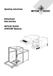
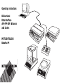
Operating instructions
Bidirectional
Data Interface
AM-/PM-/SM Balances
and Scales
0.0
g
0.0
g
METTLER TOLEDO
DataPac-M
152
.0
9
Leer
Contents Bidirectional Data Interface of the AM/PM/SM Balances and Scales – DataPac-M
1.
1.1
1.2
Overview
What are the interface capabilities?
Dialog computer/weigh. station with the aid of DataPac-M
2
3
2.
2.1
2.2
2.3
2.4
Preparation
Connector sockets of the balances
Matching the interface to the unit to be attached
Attaching units with current loop interface
Attaching units with RS232C interface
4
6
7
8
3.
3.1
3.2
3.3
3.4
Interface
How does the interface function?
Hardware handshake RS232C
General information regarding CL interface
General information regarding RS232C interface
9
10
11
12
4.
4.1
4.2
4.3
Data output
Initiating the data output
Data output using auxiliary switch
Data format
13
14
15
5.
5.1
5.2
5.3
5.4
Commands to control the balance
General information regarding command set Mnemonic
Send stable weighing result
S
Send current weighing result
SI
Send a dynamic and a stable weighing result
continuously
SR
Send stable weighing results continuously
SNR
Send all weighing results continuously
SIR
Taring
T
5.5
5.6
5.7
17
18
18
19
20
20
21
1
Mnemonic
5.8 Immediate taring
TI
5.9 Subtracting a fixed value (tare preset)
B
5.10 Change weight unit
U
Definition of a weight unit with self-selected divisor
U
5.11 Setting the vibration adapter
_ MI
5.12 Setting the weighing process adapter
; ML
21
22
22
23
24
24
5.13
5.14
5.15
5.16
5.17
5.18
5.19
5.20
5.21
5.22
Setting the stability detection
Asd
Off/on switching of Auto Zero
AZ
Off/on switching of weighing-in aid
dd
Resetting to default setting
Send identification
Calibrate
Display text
Entering limits for checkweighing/dispensing weigh.
Controlling DeltaTrac
Controlling peripherals from the balance
MS
MZ
MA
M
ID
CA
D
DY
DX
W
25
26
26
27
27
28
28
30
31
32
6.
6.1
6.2
DataPac-M
DataPac-M terminal
Defining the dialog computer – DataPac-M
D
33
34
7.
7.1
7.2
7.3
Programs to get started
Communication with the balance
Evaluation of the weighing data
Use of commands to control the balance
38
38
39
8.
8.1
Malfunctions
What happens if …?
40
2
1.
Overview
1.1
DATA
I/O
GM
200 - 240 V :
100 - 120 V :
T 63 mA
T 125 mA
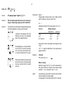
Rear of balance with interface sockets
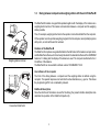
What are the interface capabilities?
The interface allows the balance to communicate with other devices, e.g. computers or
terminals. In addition, remote operation of the balance is possible. Virtually all commands which
can be entered using the Menu key can also be entered via the interface. Control is not only via
the balance display but also through acknowledgements at the interface.
The METTLER TOLEDO AM/PM/SM balances are fitted with a bidirectional data interface
(DATA I/O) and an interface for peripherals (GM) as standard. They can transmit weighing
results to a peripheral device at the DATA I/O socket via 20 mA current loop or RS232C, and
at the same time also receive commands to control the balance (full duplex operation). It is thus
possible to integrate AM/PM/SM balances in a controlled weighing system.
The interface can also be used for:
–
–
–
–
–
automatic transfer of weighing results
taring and presetting of tare
changing the weight unit
calibration
entering limits for checkweighings
and dispensing weighings
– selecting the balance operating mode (matching to weighing sample, surroundings, etc.)
– controlling the display (dialog text, DeltaTrac)
– controlling peripherals
– identifying the balance
– defining the dialog with DataPac-M terminal
Software version
The present operating instructions describe the interface inserted software STANDARD
V10.50.00. This number can be checked on the inserted software cassette or on the balance/
scale display after switching on the balance or scale.
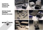
Applications, Technical Data, Accessories METTLER TOLEDO AM/PM/SM Balances and
Scales
This is the name of the brochure that is enclosed with every AM/PM/SM balance or scale. Here
you will find a complete overview of all peripherals and connection cables.
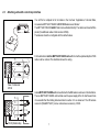
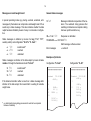
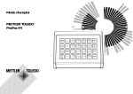
1.2
Dialog between computer and weighing station with the aid of DataPac-M
The DataPac-M includes a keypad that operates together with the display of the balance as a
weighing station terminal. This makes communication between a computer and the weighing
station possible.
Thus, for example, weighing instructions to the operator can be transmitted from the computer.
Or the operator can call up certain weighing programs from the computer, select partial programs
with yes/no, or enter article and lot numbers.
Hardware of the DataPac-M
The DataPac-M comprises a keypad attachable to the GM socket of the balance as input device
and the DataPac software, which is already included in the standard software of the AM/PM/SM
balances. For dialog text the display of the balance is used. The computer is attached to the I/
O interface of the balance.
The DataPac-M can be used after software version STANDARD V10.20.
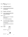
Weighing station terminal
DATA
I/O
GM
200 - 240 V :
100 - 120 V :
T 63 mA
T 125 mA
User software of the computer
The form of the dialog between a computer and the weighing station is defined using the
computer. The operator response can be limited to a few alternatives, e.g. yes/no. This allows
the programming effort to be considerably reduced.
DataPac-M description
Since the interface of the balance is used for the dialog, the present interface description also
describes the operation of the DataPac-M (section 6).
Connection DataPac-M
3
4
2.
Preparation
2.1
Connector sockets of the balances/scales
2.1.1 AM and PM balances
DATA
I/O
GM
200 - 240 V :
100 - 120 V :
T 63 mA
T 125 mA
Rear of AM/PM balances
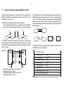
The balances have the following connector sockets:
DATA I/O:
Devices with RS232C or CL interface, e.g. a computer (bidirectional operation),
printer, GA50 Peripheral Controller, adapter cable for data output using hand or
foot switch (unidirectional operation)
GM:
DataPac-M keypad, GM instruments with adapter plug, e.g. GM303 Control Unit,
secondary display, LV10 Automatic Feeder, adapter cable for taring using hand
or foot switch.
The coding pins at the sockets prevent improper insertion.
DATA I/O
GM
Rear of high-capacity PM scales
2.1.2 SM scales
In addition to the DATA I/O and GM sockets mentioned, the SM scales have a third socket on
the underside of the weighing platform for the detachable SM terminal (scale display with keys).
Rear of SM scales
Connection socket for the SM terminal
Different terminals
The SM scales can be operated with different terminals or, if in integrated in a network, also
without terminal. As a rule, a base terminal is attached to the scale that has either a fluorescent
display (VFD) or a liquid crystal display (LCD) (terminal model SM-F or SM-L). For special cases,
so-called application terminals with integrated DataPac-M keypad are available (terminal model
SM-AF with VFD or SM-AL with LCD).
Computer-controlled multistation weighing system with SM scales without terminal
If one or more weighing platforms of the SM scales are attached directly, i.e. without terminal,
with the aid of the serial interface to a computer, each weighing platform must be fitted with an
34490 system connector.
The SM scales do not recognize any standby operation and could not be switched on even via
the interface after a power outage. The system connector allows standby operation and is
inserted in the same place where the absent terminal would be attached. It keeps the weighing
platform permanently switched on.
SM terminal connector or
system connector
at base of scale
5
6
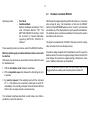
2.2
Matching the interface to the unit to be attached
(configuration)
The configuration is described in detail in the operating instructions and
is thus repeated here only in brief.
To select the interface parameters, first the configuration register
has to be entered as follows:
– Switch of balance/scale ➝ standby
no display.
–
press control bar and
keep pressed until
then release bar so that
------ConF-
appears,
rESEt
appears.
When in the configuration register, briefly pressing the control bar
allows switching from the sector “rESET” to the sectors “SCALE”,
“Unit” or “I-FACE”.
In an individual sector, the desired parameter is selected by pressing
and holding the control bar and then its value is determined by pressing
the control bar briefly (default value = black).
2.2.1 Sector "I-FACE"
Data transmission mode (see section 4):
S. Stb
S. ALL
S.Auto
S.Cont
stable single values
current single values (stable or not)
stable single value after each weight change
all values, continuous
Transmission rate (baud rate):
b 110
110 baud
b 2400
2400 baud
b 9600
9600 baud
Parity:
P
E
P -0P -SP -N-
Even
Odd
Space (use for 8-bit code)
Mark (use for “no parity”)
Pause between data lines and handshake:
PAUSE .0
for rapid peripherals (computer etc.)
PAUSE H
utilize handshake line
PAUSE 1
for slow peripherals (printer etc.),
PAUSE 2
1.0 or 2.0 sec. pause between the data lines
Auxiliary (suppression of auxiliary symbols)
Au oFF
Result with certification symbol <…> or * in animal wgh.
Au on
Suppression of these auxiliary symbols
2.2.2 Sector "Unit"
Start data output
With the AM/PM balances, which have only a control bar, this can also
be used as an alternative method of initiating the data output.
Art oFF
Art on
Control bar normal
Control bar + print/data output/start function
2.2.3 Sector "rESEt"
Resetting to default parameters (black):
YES
– Press key and
keep pressed until
-Endo
8.88
g
appears.
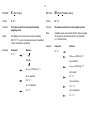
2.3
Attaching units with current loop interface
You will find a complete list of all cables in the brochure “Applications, Technical Data,
Accessories METTLER TOLEDO AM/PM/SM Balances and Scales”.
DATA
I/O
GM
200 - 240 V :
100 - 120 V :
T 63 mA
T 125 mA
The METTLER TOLEDO GA44 Printer can be attached directly. The cable is enclosed with the
printer (for additional cables: Order number 47926).
The balance should be configured with the default values.
+
15
10
5
4
For the attachment of other METTLER TOLEDO units with CL interface (solder side) the 47936
cable must be ordered. The illustration shows the wiring.
9
7
6
1
2
+
View of cable side
47936
15
10
A non-METTLER TOLEDO unit can be attached to the BB balance as shown in the illustration.
The non-METTLER TOLEDO unit must take over the power supply of the CL interface and here
it is essential that the limiting data described in section 3.3 are observed. The I/O balance
connector (“MiniMETTLER”) can be ordered as an accessory: 33930.
9
7
6
33930 (Solder side)
7
8
2.4
Attaching units with RS232C interface
You will find a complete list of all cables in the brochure “Applications, Technical Data, Accessories METTLER TOLEDO AM/PM/SM Balances
and Scales”.
Prepared cables are available for the following units:
33640
33995
Printer
EPSON P-40
Computer EPSON PX-4
HX-20
Order No. 33688
33982
33955
For other units with an RS232C interface, cables with freely attachable contacts can be
ordered. One end of the cable carries the permanently attached I/O balance connector, the other
end the connector with the freely attachable contacts.
Order No.
33640
33995
33783
Cable set with 25-pin connector (male), e.g. for printer
Cable set with 25-pin coupling (female), e.g. for IBM-PC, IBM-XT
Cable set with 9-pin coupling (female), e.g. for IBM-AT, Toshiba T1000
Depending on whether the unit to be attached is a data terminal unit (DTE see also 3.4) or a data
communications unit (DCE), the cable must be wired as follows:
11
6
1
33783
Connector, view from cable end
1
13
25
14
1
6
5
9
Balance
Description of the function
DTE
DCE
DTE
DCE
2, green
12, brown
13, white
3, yellow
data (commands) for balance
data from balance
signal ground
handshake for balance
3
7
4/20
2
2
7
5/6
3
2
5
4/7
32
3
5
6/8
6/5
4
20
7/4
8
6
1
8/6
7
4
short-circuiting link
(optional)
20/4
5
6
8
3.
3.1
Interface
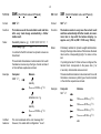
How does the interface function?
The 10th bit (stop bit) is again “high” and shows the end of the
transmission for this character. A chain of characters transmitted
successively is called a data string.
Serial data transmission
T
T
T
T
The AM/PM/SM interface
High
The balance has an RS232C voltage-controlled data interface and a
passive 20 mA current loop interface (CL), both led out to the
DATA I/O socket.
These interfaces can be used both unidirectionally and in bidirectional
full duplex operation.
The data outputs of both interfaces operate in parallel. Both outputs can
be used at the same time, but only one input either CL or RS232C.
Low
Start Bit Bit 1 Bit 2
Bit 7 Parity Stop Bit
The data are transmitted serially, i.e. character by character one
character after the other. Each character is represented by a 7-bit
binary code. The individual bits of the character are also transmitted
serially. A wire pair thus suffices for the data transmission in one
direction.
The data inputs are ready to receive as soon as the display has been
switched on. The data outputs remain blocked until the start routine is
complete.
In the idle state (no data transmission), the relevant data line is active
(20 mA quiescent current with current loop, potential “high” with
RS232C).
Transmission principle: serial by bit, asynchronous (1 start bit), 7-bit
code ASCII ISO646 + parity bit, 1 stop bit
(receive), 2 stop bits (send)
The transmission of a 7-bit character is initiated with a start bit
(transition from 20 to 0 mA or “high” to “low”) followed by the 7 data bits.
The order of the data bits starts with the least significant bit (LSB) and
ends with the most significant bit (MSB).
In bidirectional operation, switching off the other device or a break in the
interface cable (BREAK) resets the balance/scale to the configured
status. In other words, all functions that have been triggered by
commands via the interface (transmission mode, tare preset, text
display, etc.) are reset.
A subsequent parity bit allows the correctness of the data transmission
to be checked. It is added to the number of “1’s” of the data bits of a
character to make an even or odd number (even or odd parity).
Configuration of the interface parameters is described in section 2.2.
9
10
3.2
Operating modes:
–
–
Free Mode
Handshake Mode
Software handshake according to “Technical Information Bulletin” TIB: “The
METTLER TOLEDO CL Interface”. Order
No. in section 3.3 “General information
regarding METTLER TOLEDO CL
interface”.
These operating modes can also be used for the RS232C interface.
Matching of data supply and demand between balance and unit to
be attached
Data losses can selectively be prevented as follows without the need
for handshake lines:
1. With the handshake mode (software handshake)
2. With an adjustable pause time between the data strings of up to
2 seconds.
3. By selective request of the weighing result with the command
SI CRLF . If the balance can not provide a valid result, it sends “SI”
immediately. The controlling computer is thus informed at all times
that it must once again request a measured value.
The hardware handshake described in what follows also offers a
possibility to control the data flow.
Hardware handshake RS232C
With the aid of a separate signal line (DATA I/O socket pin 3, connection
cable yellow litz wire), the transmission of data via the RS232C
interface of the AM/PM/SM balances can be “curbed”, i.e. the balance
sends data only if the attached device reports operational readiness.
The attached device must have handshake functions and be wired in
accordance with section 2.4.
The signal is evaluated when “PAUSE H” has been set in the configuration and when the line is actually wired up.
If a positive voltage is applied to the handshake line or if it is open, the
balance sends. In the case of a negative voltage it does not send. If the
level changes from positive to negative during a transmission, maximum 2 additional characters are transmitted.
If this handshake function is used, the data output may not be
triggered with an auxiliary switch as described in section 4.2.
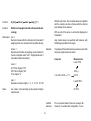
General information regarding CL interface
The CL interface of the balance is primarily suitable for transmissions
over relatively long distances (> 15 m) or for operation of the balance
in the case of severe power line disturbances. It is completely separated
galvanically from the balance by an optocoupler and thus prevents the
intrusion of disturbances in the electronics.
The passive current loops of the balance must thus be supplied by
external current sources. To avoid damage to the CL interface by these
external current sources, it is essential to observe the following limiting
data:
I
(mA )
The CL interface has two passive transmission loops independent of
each other.
The U/I characteristic
of the source must lie
within the hatched
area.
I max 30 mA
P max 800 mW
U max 40V
3.3
U
passive
passiv
Balance
active
aktiv
40 ( V )
The interfaces of the METTLER TOLEDO units require the following
specifications:
– voltage excursion of source 15 V (+10%/–0%)
– current (high) between 18 mA and 24 mA
– rate of change 2...20mA/µs
– cable:
shielded, twisted pairs,
0,14 mm2, 125 ohm + 130nF/km
max. length: 1000 m/300 baud, 500 m/2400 baud
Peripheral
For further information see also “The METTLER TOLEDO CL Interface”,
720106 (German), 720107 (English), 720108 (French),
720109 (Spanish).
11
12
3.4
General information regarding RS232C interface
Voltage-controlled interface in accordance with the standards EIA
RS232C, DIN 66020. These standards conform to the CCITT recommendations V.24 and V.28.
A distinction is made between two types of equipment:
– Data Terminal Equipment (DTE), e.g. teleprinter, printer, IBM-PC
– Data Communications Equipment (DCE), e.g. modem, transmitter
RS232C
For short distances (< 15 m) where data highways are not practical, the
RS232C interface is also used for any two units, i.e. the combinations
DTE – DTE and DCE – DCE are entirely possible. Certain signals and
lines can be omitted in such cases. A minimum configuration can be
implemented with two (unidirectional operation) or three lines (bidirectional operation).
2
3
7
RS232C
2
3
7
DTE
DTE
DCE
DCE
DTE
The RS232C interface was originally conceived to link such data
terminal equipment with data communications equipment. The lines
and signals have been designed for this original configuration, which is
still in use today.
Example:
S
E
DTE
1
2
3
4
5
6
7
8
E
–
A DTE unit sends its data via connection 2
(data direction DTE ➝ DCE).
A DCE unit sends its data via connection 3
(data direction DCE ➝ DTE)
DTE
2
3
7
DTE
DCE
2
3
7
DCE
In addition to the above-mentioned interface lines the most common
handshake lines are shown below:
DCE
DTE
Modem
2
3
7
1
2
3
4
5
6
7
8
20
Protective Ground
Transmit Data
Receive Data
Request to Send
Clear to Send
Data Set Ready
Signal Ground
Data Carrier Detect
Data Terminal Ready
TxD
RxD
RTS
CTS
DSR
GND
DCD
DTR
1
2
3
4
5
6
7
8
20
The definition of the above terms is from the angle of the DTE.
DCE
Computer
–
2
3
7
S
23
24
25
DCE
4.
4.1
Data output
Initiating the data output
S. Cont
The balance has always a current weighing result available that can
either be stable or unstable, valid or invalid. All four combinations are
possible.
Depending on the application, the data output can be initiated in the
following ways:
–
–
–
–
–
In bidirectional operation these transmission modes can be selected
via the interface with send commands (see section 5), irrespective of
the configured transmission mode.
Print key or control bar of the balance
external print key (auxiliary switch or “PRT” key on GA44)
automatic operation (configuration: “S.Auto”, “S.Cont”)
commands via the interface (send commands)
loading or unloading the balance (send commands “SR”, “SNR”)
Transmission mode
corresponding send command
S. Stb *
S
S. All *
SI
S. Auto
SNR
S. Cont
SIR
* initiate transmission with key
The default setting for the data transmission mode is:
S. Stb
A stable single value is transmitted if the data transmission has been triggered by a key.
The transmission mode can be modified in the configuration register
(I-Face), (see also section 2).
S. All
A current single value (stable or unstable) is transmitted
if the data transmission has been triggered by a key.
S. Auto
A stable value is automatically transmitted after every
load change. (Magnitude of change, see Table under
SNR command, section 5.5.)
All values are transmitted automatically in step with the
configured pause – with “Pause 0” in step with the
display update speed, see also SIR command, section 5.6 – or with handshake.
Nonstable weighing results are marked in the identification block with “SD” and stable ones with “S/” (see
section 4.2, Data format).
In the case of an interface break, the transmission mode is lost if it has
been selected via the interface. On the other hand, the configured
transmission mode remains stored until a new one is configured.
Note:
13
The default setting for the pause between the data
strings is 1 second (for GA44 Printer). In the case of
operation with a computer this pause is too long. Therefore, in most cases, it has to be configured at (0).
14
4.2
Data output using auxiliary switch
42500
GM303
47473
46278
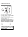
The data output can be initiated by a hand or foot switch.
If a hand switch is needed directly at the balance for the AM/PM
balances, the GM303 Control Unit can be installed.
If the switch has to be positioned somewhat apart from the balance, a
separate hand or foot switch can be used.
An adapter cable is also needed for the attachment of this switch. This
extends the I/O interface socket of the balance to the rear and carries
a 2-pin socket on a Tee joint for attachment of a hand or foot switch.
Adapter cable
Hand switch
Foot switch
Order No.
47473
42500
46278
If the data output is triggered using the auxiliary switch (or by means
of the PRT key at the GA44 Printer), the handshake function
described in 3.2 is not possible.
4.3
Data format
Format of weighing result
Each valid weighing result is available at the data output in a standard
format. The data string can be divided into three blocks. It is always
terminated with Carriage Return (CR) and Line Feed (LF).
Char.
Information
04…12
Weighing result
Code Explanation
x
/ = (Space)
01
02
03
04
05
06
07
08
09
Identification block
Data block
Char.
Information
01
Type of data
initiation
11
12
13
14....
C
R
L
Outside the DeltaRange or if unstable results, the last digit is shown as
a /. Drops therefore the decimal
point, it will be replaced by /.
F
Unit block
14...
Code Explanation
/
triggered from the balance
with auxiliary switch or print key,
or animal weighing, triggered in
any way
S
02
10
/
/
Status messages /
D
*
9 characters, result right-aligned
including sign “–” directly in front of
the first numeral, decimal point;
leading zeros are replaced by spaces.
Weighing unit
x
0…4 characters, terminated immediately with CR LF: g or one of 10 other
units, depending on requirements.
Example:
SD////-24.37/g CR LF
triggered via the interface with
Send commands or balance in the
“Send Continuous” mode
(“S.Cont”)
stable result
unstable result (dynamic)
animal weighing1)
1)
15
* can be replaced by /, if “Au on” is
configured in sector I-FACE.
16
Messages on invalid weight result
General status messages
In special operating modes (e.g. during overload, underload, error
message etc.) the balance can not provide a valid weight result. It thus
sends only a status message. This also indicates whether the data
output has been initiated by means of a key or command or configuration.
TA CR LF
Message in bidirectional operation of the balance: The automatic taring process after
switching on the balance is complete or taring
has been performed with a key.
CB/< Text > CR LF
Response on calibration
Status messages on initiation by means of a key (“Print”, “PRT”,
auxiliary switch) and configuration “S. All”or “S. Cont.” :
/I CR LF
/I + CR LF
/I - CR LF
invalid result2)
overload
underload
STANDARD ///V10.50.00 CR LF
Error messages
Start message, software version
→ section 8
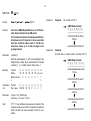
Examples of printouts
Status messages on initiation of the data output by means of commands or through the transmission mode “S.Cont”:
C
L
SI R F
SI + CR LF
SI - CR LF
invalid result
overload
underload
If the balance transmits neither a result nor a status message after
initiation of the data output, this means that it is waiting for a stable
weight value.
2)
Configuration “S. Cont”
Configuration “S. All”
2)
e.g. data transfer during taring process which could not be completed
because of instability
********************
********************
Standard
V10.50.ØØ
S
-Ø.Ø2 g
SI
TA
S
Ø.ØØ g
SD
8.2 g
SD
2ØØ.4 g
SI+
S
195.47 g
S
195.46 g
Standard
V10.50.ØØ
-Ø.Ø5 g
I
Ø.ØØ g
D
17.8 g
19.25 g
19.24 g
19.24 g
5.
5.1
Commands to control the balance
General information regarding command set
Interface commands and applications
Commands that intervene in an application, abort this application.
AM/PM/SM balances with full duplex interfaces can not only send
weighing results but also receive control commands at the same time.
These commands are described in what follows.
For example, the U command terminates the unit switching by means
of the control bar. The D, DY and B commands terminate piece
counting (Stk, PCS) and percent calculation (%).
Entry of cammands
Switching on the balance
After software version STANDARD V10.42, uppercase or lowercase
letters can be used for commands.
In bidirectional operation of the interface the handshake is set up on
startup before the switch-on zero has been determined. It is thus
essential that the computer waits for the message “TA” from the
balance before it sends commands. Otherwise, it must be anticipated
that, e.g. SR and B commands are overwritten during this operation.
Each command must be terminated with the character sequence
CARRIAGE RETURN (CR) und LINE FEED (LF).
Per command, maximum 64 text characters are possible incl. CR LF.
A command without associated parameters generally resets the appropriate function.
Note:
Communication failures
Commands that could not yet be executed are overwritten by newly
received ones, i.e. they are lost.
Simple examples for application programs can be found
in section 7.
A BREAK condition (see section 3) clears all commands and the
balance again behaves as if it had been switched off and then on.
The following symbols are used in this section:
/
space
If the balance has not received a command properly or can not evaluate
or execute it, it sends an appropriate error message (see section 4.3).
: = definition
parameter
[]
parameter
optional
17
18
5.2 Cmd:
S
Format:
S
Function:
The balance sends the next possible stable
weighing result.
Notes:
On stability, the current result is sent immediately.
With “S CR LF” send commands previously transmitted
can be cancelled by overwriting.
Example:
Computer
S
C
C
(Send value)
5.3 Cmd:
SI (Send Immediate value)
L
R F
Format:
SI
Function:
The balance sends the current weighing result.
Note:
Unstable results are marked with the status message
“D” (dynamic); with valid results “SI” is transmitted.
(→ 4.3 Data format).
Example:
Computer
Balance
L
R F
SI
C
C
L
R F
Balance
L
R F
SD////98.54/g CR LF
stability
or on stability
S////100.00/g CR LF
S////100.00/g CR LF
or if invalid
or on overload
SI+
C
SI
C
L
R F
L
R F
or on overload
or on underload
SI+
SI- CR LF
or on underload
SI-
C
C
L
R F
L
R F
5.4 Cmd:
SR (Send value and Repeat)
Format:
SR [ /threshold ] CR LF
Function:
Parameter:
Notes:
Example:
Computer
SR
The balance sends the next possible stable result
and then on each load change of a certain magnitude
a dynamic and the subsequent stable result.
C
Balance
L
R F
stability
S////100.00/ g CR LF
The magnitude of the load change can be entered in
absolute terms as a threshold value, in the weight unit
selected under “Unit 1”, numerical value at least 3d*.) If
only “SR CR LF” is entered, the magnitude is 12.5% relative to the last stable value or at least 30d*.
deflection
SD///115.78/ g CR LF
The entry of a threshold value is advisable primarily in
automatic additive weighing operation. Here, an absolute response threshold is necessary since with “SR CR LF”
the threshold fixed as a relative value would increase
with increasing total weight.
stability
S////150.00/ g CR LF
etc.
This automatic transmission mode remains in force until
the balance receives some other send command or the
interface experiences a break.
* d = digit = smallest display increment
Certified
balances:
The SR command leads to the error message “EL”.
However, it is usable after configuration “Au on”.
If threshold is not added, the load change is 25% or 30 d.
19
20
5.5 Cmd:
SNR
Format:
SNR
Function:
The balance sends the next stable result and then
after every load change automatically a further
stable result.
Notes:
Readability balance (g)
0,0001 0,001 0,01 0,1 1
Load change (g) ≥
0,2
C
(Send Next value and Repeat)
L
R F
1
1
1
5
5.6 Cmd:
SIR
Format:
SIR
Function:
The balance sends in every case the current result
and then automatically all further results, at a maximum rate in step with the balance display (i.e.
approx. every 130 ms; SW < 10.50 every 160 ms).
Notes:
Particularly suitable for dynamic weight determination.
Owing to the large data volume of the balance the baud
rate must be correspondingly high if no value is to be
lost.
In contrast to the SR command no dynamic values are
transferred.
This automatic transmission mode remains in force until
the balance receives any other type of send command
or the interface experiences a break.
Example:
Computer
SNR
C
Balance
This automatic transmission mode remains in force until
the balance receives any other type of send command
or the interface experiences a break.
R FF
stability
Example:
Computer
SIR
deflection min. 1 g
stability
Certified
balances:
L
R F
If a printing interval of 0.0 has not been configured, the
transmit clock corresponds to the pause time (1 or
2 seconds). Intermediate values are lost.
L
S////100.00/ g CR LF
C
(Send Immediate value and Repeat)
C
Balance
L
R F
SD////98.54/ g CR LF
SD////95.76/ g CR LF
S////150.00/ g CR LF
SD////95.32/ g CR LF
etc.
S/////95.40/ g CR LF
This command leads to the error message “EL”.
However, it is usable after configuration “Au on”.
etc.
5.7 Cmd:
T
5.8 Cmd:
TI
Format:
T CR L F
Format:
TI CR LF
Function:
With this command, taring can be performed via the
interface and the balance switched on again after a
power outage.
Function:
The balance is tared immediately without waiting for
stability.
Notes:
Notes:
If an SI or an SIR command follows a T command while
the balance is still waiting for stability, it returns “SI”.
If no stable condition has been attained after approx.
10 s, the error message “EL” follows.
Applications for this command are:
– Taring of the balance during a consumption measurement or during a continuous dispensing operation.
– Taring from a computer that defines the stability
criterion itself.
– Taring in an externally clocked system.
(Tare)
With the AM/PM balances, –OFF– appears in the display
after a power outage. The balance can be switched on
again with "T CR LF"
If taring is by chance performed below the startup zero
point the balance must store this zero point again. As
here a high stability is necessary; taring can take up to
12 s. No acknowledgement follows when the operation
is complete.
The time needed for taring can vary; no acknowledgement is sent when it is complete. In the case of
overload/underload, taring can not be performed. The
error message “EL” is sent immediately.
Example:
Computer
Balance
T CR L F
Instability:
(Tare Immediately)
Example:
Computer
Balance
TI CR LF
Unstable or stable state:
0.00g
– – – – – – (wait)
Stability: 0.00 g
21
22
5.9 Cmd:
B
Format:
B [ /offset ] CR LF
Format 1:
U [ /unit ] CR LF
Function:
After receipt of this command the balance continuously subtracts the value offset from all weighing
results (tare preset).
Function:
Selection of the weight unit.
Parameter:
unit : =
g, kg, lb, oz, ozt, tl, GN, dwt, ct, C.M., k., no entry (no
display of unit, Display value in the base unit of the
balance.
Parameter:
(Base)
5.10 Cmd:
offset : =
Numerical value, max. 7 digits.
Enter sign only for negative values. “B CR LF” cancels the
command.
offset refers to the unit that has been programmed in the
configuration under Unit 1. The value must lie within the
admissible weighing range, i.e.
offset + tare weight = 0…maximum load.
Example:
Uppercase letters can also be entered.
Note:
The entered U command remains active until it is overwritten by another command or the interface experiences
a break.
Example:
Computer
The tare symbol appears in the display. Taring cancels
the offset command. If the offset value is outside the
weighing range, the error message “EL CR LF“ will be
transmitted.
Computer
Balance
Display: 2054 g
U/kg CR LF
Display: 2.054 kg
Balance
Display: 0.00 g
B/100 CR LF
(Unit)
Entry of “U CR LF” only cancels the U command and switch
back to the unit which is configured under Unit 1.
offset is rounded off to the balance resolution before
calculation.
Notes:
U
Display: -100.00g
Certified
balances:
As unit, only units allowed by the respective Bureau
of Standards can be selected.
Format 2:
U [dec ] /divisor [ /name [ /step ] ] CR LF
Function:
Definition of a weight unit with self-selected divisor
(scaling).
Without entry of dec, the converted values are outputted
with the maximum number of places after the decimal
point allowed by the balance.
With no entry of the name, no unit is either displayed or
transmitted.
Parameters: dec : =
Number of places after the decimal point (truncated if
weighing result more accurate than resolution allows).
step should always be specified with balances with
DeltaRange (recallable fine range).
divisor : =
Number which divides all weighing results referred to
the unit configured under “Unit 1”. Magnitude at least 1
d (smallest readout increment).
Example:
Computer
Balance/scale
Load 1 PCS
name : =
#, PCS for display “PCS”
STK, Stk for display “Stk”
% for display “%”
Notes:
Programing of the balance/scale as a piece counter with
the piece weight entered as divisor.
123.4 g
U 0/123.4/PCS /1
C
L
R F
1 PCS
step : =
Readout increment in digits: 1, 2, 5, 10, 20, 50, 100
Load 50 PCS
dec , divisor , name and step can be used according to
requirements.
50 PCS
Certified
balances:
23
The U command leads to the error message “EL”.
However, it is usable after configuration “Au on”.
24
5.11 Cmd:
MI
5.12 Cmd:
ML (Modify display adaption) after SW version 10.42
Format:
MI [ /number ] CR LF
Format:
ML [ /number ] CR LF
Function:
Setting the vibration adapter
(configuration of the balance via the interface)
Function:
Parameter:
number : =
Setting the weighing process adapter and selection
of the animal weighing mode or start of animal
weighing (configuration of the balance via the interface)
Parameter:
number : =
Balance display
1 In dispensing, all decimal places
are always displayed
˛
2 In dispensing/weighing, the last
decimal place is suppressed until
stability (default setting) except if
“dd off” has been selected
;
3 Absolute weighing, - - - - - - is
displayed during weighing until
stability
∞
4 Select animal weighing mode or
start animal weighing
,
(Modify ambient vibration) after SW version 10.42
Balance display
1 Very stable surroundings
short weighing time
—
2 Normal surroundings
(default setting)
_
3 Unstable surroundings
relatively long weighing time
–
"MI CR LF" resets the vibration adapter to the default
setting.
Note:
Example:
The weighing time also depends on the balance model,
readout increment and on whether the animal weighing
mode has been selected.
Computer
Balance display
MI/3 CR LF
–
Entry of "ML CR LF" resets the weighing process adapter
to the default setting.
Notes:
When used for the first time, the command “ML/4”
selects the animal weighing mode; in all other cases it
starts an animal weighing.
5.13 Cmd:
MS (Modify stability detection) after SW vers. 10.42
Format:
MS [ /number ] CR LF
Function:
Setting the automatic stability detection (configuration of automatic stability detection “ASd” via the interface)
Parameter:
number : =
The cycle time is selected with the MI command:
— approx. 4 s
_ approx. 6 s
– approx. 8 s
1
Coarse for good weighing results not with standing
unstable surroundings; the balance recognizes stability despite small fluctuations.
2
Default setting
3
Fine
4
Very fine, for best weighing results in stable surroundings; the balance recognizes stability only if the
fluctuations remain very small.
The result is marked with “/” for identification if the
configuration has not been changed with “Au on”.
Example:
Computer
ML/1
C
L
R F
Balance display
∞
“MS CR LF” resets the stability detection to the default
setting.
Example:
Computer
Balance display
MS/4 CR LF
As soon as the surroundings are
completely stable, the ASd indicator disappears.
25
26
5.14 Cmd:
MZ
5.15 Cmd:
MA
Format:
M Z [ /number ] CR LF
Format:
MA [ /number ] CR LF
Function:
Off/on switching of Auto Zero (configuration of Auto
Zero “AZ” via the interface)
Function:
Off/on switching of weighing-in aid
(configuration of the DeltaDisplay “dd” via the interface)
Parameter:
number : =
Parameter:
number : =
Notes:
(Modify Auto Zero) after SW version 10.42
0 off
0 off
1 on (default setting)
1 on (default setting)
"MZ CR LF" resets Auto Zero to the default setting
"MA CR LF" resets the weighing-in aid to the default
setting.
Auto Zero corrects zero point drifts or contamination of
the weighing pan automatically, but only in the range of
the internal decimal places not displayed.
Note:
At the start of weighing-in during rapid dispensing, the
DeltaDisplay suppresses the last place of the balance
display. In fine dispensing, it is switched on again.
Example:
Computer
Balance display
MA/CR LF
In dispensing/weighing the last
decimal place is suppressed until
fine weighing-in.
Conditions for response of Auto Zero are:
Balance display must show 0000000 and ASd indicator
must have blanked out for at least one weighing cycle
(depends on balance model).
Example:
(Modify DeltaDisplay) after SW version 10.42
Computer
MZ/0
C
L
R F
Balance display
no visible effect (the zero point is
no longer automatically corrected)
5.16 Cmd:
M
5.17 Cmd:
ID (Identify)
Format:
M CR LF
Format:
ID CR LF
Function:
Simultaneous resetting of all M commands to the
default setting
Function:
The balance sends its identification (3 lines):
Notes:
For all M commands, it generally holds that they should
not be used dynamically.
(Modified settings reset) after SW version 10.42
< Software Version >
TYPE: < balance type >
INR: < identification number >
When an interface break (BREAK) occurs, the settings
made with the M commands are lost. In contrast to the
send commands, the settings are reset to the default
setting and not to the values configured using the Menu
key.
Example:
Computer
M CR LF
Example:
Balance
Default setting of all configurations initiated via the interface
27
STANDARD
TYPE :
INR
:
V10.50.00 CR LF
PM 4600 CR LF
720889 CR LF
28
5.18 Cmd:
CA (Calibrate) after SW version 10.45
Format:
CA CR LF
Function:
The balance is calibrated.
With balances without a built-in (internal) calibration
weight, the value of the (external) calibration weight to be
loaded appears in the display. The following display
0.000 g signals that the balance should be unloaded.
5.19 Cmd:
D
Format:
D /text [ ; unit [ symbol ] ] CR LF
Function:
A text combined with a weight unit and a weight
symbol is displayed. “D xCR LF” clears the display,
“D CR LF” frees it again for the weight display.
The balance continues to operate normally during the
display. The execution of send commands is not affected.
The progress of the calibration is reported via the interface.
Computer
CA
C
Balance
L
busy
R F
CB///– – – – – – – CR LF
*
*
CB////0.000/ g CR LF
if loaded, balance must be
unloaded
CB///200.000/ g CR LF
load calibration weight
*
* These steps are unnecessary with balances
with an internal calibration weight.
(Display)
CB////0.000/ g CR LF
unload balance
CB/1 CR LF successful or
CB/0 CR LF unsuccessful or
EL CR LF inadmissible
G
B
N
T
AZ
8.8.8.8.8.8.8
8.8.8.8.8.8.8
Parameter:
text : =
All printable characters of the ISO646 code table. The
limited representation by the 7-segment display should
be taken into account.
text is shown left justified. If text is longer than the
balance display allows, the section first inputted is cut
off.
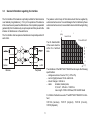
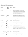
Representation of text characters in balance display
unit : =
Balance display
The following table shows the 7 segment display for all 95 printable
characters of the ISO 646 code table.
U
#, PCS
STK,Stk
%
g (kg, lb, …; selected unit)
PCS
Stk
%
symbol : =
Balance display
B
B (brutto = gross)
N
N (net)
T
T (tare)
G
G (gross)
'. w
õ
ú ` ê ëè
'
[
]
°
K
.
-
.
ê
-é
SP
!
"
#
$
%
&
'
(
)
*
•
,
-
.
/
0
1
2
3
4
5
6
7
8
9
û
ê
c
≠
c
2
ø
1
2
3
4
5
6
7
8
9
:
;
<
=
>
?
c
A
B
C
D
E
F
G
H
I
J
K
L
M
N
O
@
A
B
C
D
E
F
G
H
I
J
K
L
M
N
O
P
Q
R
S
T
U
V
W
X
Y
Z
ò
4
ô
m
_
P
Q
R
S
T
U
V
W
X
Y
Z
[
\
]
`
_
`
a
b
c
d
e
f
g
h
i
j
k
l
m
n
o
`
a
b
c
d
e
f
g
h
i
j
k
l
m
n
o
P
q
r
s
t
u
v
w
x
y
z
ñ
l
ó
å
p
q
r
s
t
u
v
w
x
y
z
{
|
}
~
Note:
While the D command is effective, a * is shown in the top
left of the display. It indicates that the display is no longer
linked with the balance, but is controlled via the interface.
Examples:
Computer
Balance display
400.0 g
D/ Prog . 5
C
L
R F
* Pro9. 5
N
D/ 285.94; UN
29
Certified:
balances
C
L
R F
* 285.94 g
For unit only “U” can be selected if “Au on” has been
configured beforehand.
30
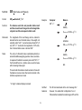
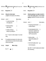
5.20 Cmd:
DY
Format:
DY [ /target [ /tol 1 [ /tol 2 ] ] ]
Function:
Entry of target weight and tolerances for checkweighings or dispensing weighings with the DeltaTrac.
Function:
(Display Y)
C
L
R F
Parameters: target : =
Target weight; numerical value, max. 7 digits, decimal
point as required, minimum value 100 d.
tol. : =
Admissible deviation from target weight, min. 2.5 d
The DeltaTrac is controlled so that it supports dispensing
and checkweighings by analog, optical signals.
Definition
2 tolerance vanes appear above the
DeltaTrac and show the admissible
limits of the weight deviation.
none
tol 1
tol 1 and tol 2
Weight deviation
downward (-)
upward (+)
-2,5%
tol 1
tol 2
+2,5%
tol 1
tol 1
target and tol refer to the weight unit configured under
“Unit 1”.
During weighing-in, a coarse indicator
moves from 9 o-clock in the direction
of 6 o-clock and a fine indicator from
9 o-clock in the direction of 12 o-clock.
“DY CR LF” resets the DeltaTrac to the usual dynamic
graphic indicator.
Example:
Computer
DY/ 200/18/9 CR LF
When the fine indicator is between the
two tolerance vanes, the target weight
has been reached with the selected
accuracy.
Balance display
DeltaTrac range from 6 to 12 o-clock corresponds to
200 g, fine indicator at –tolerance vane means weight
deviation = –9 g, at +tolerance vane = +18 g.
Notes:
A possible tare preset with the aid of the B command
must be added to the target weight.
A subsequent DX command clears the DY command.
5.21 Cmd:
DX (Display X) after SW version 10.42
Format 1:
DX [ /number [ /number ] ] [ /T ] CR LF
Function:
Control of one or two indicators and the tolerance
vanes of the DeltaTrac
Format 2:
DX [ /number [ - number ] ] [ /T ] CR LF
Function:
Control of a range between two indicators and the
tolerance vanes of the DeltaTrac
Parameter:
Number : =
Natural number in the range 0…59, corresponding to
the minutes of a clock.
"DX CR LF" fades out the controlled indicators.
Notes:
The DX command is intended for a static display. For
dynamic control of the DeltaTrac as a weighing-in aid
etc., DY should be used.
A DY command following a DX command clears the DX
command.
Examples:
Computer
DeltaTrac
DX/15/45/T CR LF
DX/15 - 23 CR LF
31
32
5.22 Cmd:
W
Format:
W /s0 [ /t1 /s1 … /t4 /s4 ]
Function:
Parameter:
Example:
(Write )
Example 1:
L
R F
Control of a GM54 Output Module or an LV10 Automatic Feeder attached to the GM socket.
The 8 output contacts are closed/opened with the 8bit status word s0 . If required, it can be overwritten
after time t1 with the status word s1. The W command thus allows up to 4 status changes to be
preprogrammed.
s (status) =:
Decimal value between 0…255, corresponding to the
8-digit binary number which opens/closes the output
contacts C0…C7. Contact closed = binary value 1.
Contact
C7 C6
Status
off off
Binary numb. 0 0
s
C5 C4
off off
0 0
C3
off
0
C2
off
0
C1 C0
on on
1
1
3
C7 C6
128 64
C5 C4
32 16
C3
8
C2
4
C1
2
Calculation
of s:
Contact
Dec. value
Parameter:
t (time) =: 25…65535 (ms)
Accuracy: ± 3%, max. ± 50 ms
Note:
C
C0
1
"W CR LF" or an interface break opens all contacts. If the
computer sends a second W command to the balance
before the first has been executed, the first is overwritten.
Computer
W/1/500/130 CR LF
GM54 Output module
C7 C6 C5 C4 C3 C2 C1 C0
---------------------------------off-off-off-off-off-off-off-on
500 ms
on-off-off-off-off-off-on-off
Example 2:
Computer
W/255/100/ 2 /200/8/300/ 32/400/128 CR LF
GM54 Output module
C7 C6 C5 C4 C3 C2 C1 C0
------------------------------------on-on-on-on-on-on-on-on
100 ms
off-off-off-off-off-off-on-off
200 ms
off-off-off-off-on-off-off-off
300 ms
off-off-on-off-off-off-off-off
400 ms
on-off-off-off-off-off-off-off
6.
DataPac-M
6.1
A
B
7
8
9
C
D
4
5
6
E
F
1
2
3
G
H
0
.
–
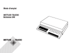
DataPac-M keypad
CLEAR
ENTER
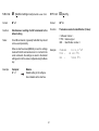
DataPac-M terminal
The DataPac-M terminal has three key fields:
– Function keys A…H, independent of the other keys.
– Numeric keypad 0…9 with decimal point and sign – (These keys can also be programmed
as additional function keys.)
– Correction key CLEAR and termination key ENTER, the latter can also be programmed as
a PRINT key.
The keypad operates together with the balance display as a terminal which sends and receives
data and can thus enter into dialog with a partner device, usually a computer.
With the aid of the enclosed felt pen, the function keys can be inscribed according to the
application requirements. The inscription can be removed with alcohol.
The keypad is provided with a cable with a MiniMettler connector and can be plugged into the
GM socket at the rear of the balance.
Function keys
When one of these keys is pressed, the DataPac-M immediately sends the key code KF/…(Key
Function) to the computer:
Computer
DataPac-M
KF/ A CR LF
AB…H
KF/ B CR LF
Note:
The function keys can also be pressed during
a numeric entry without influencing it.
:
KF/ H CR LF
Other keys
Their action differs according to the application. It is described in what follows.
33
34
6.2 Cmd:
D
Format:
D [format ] [ x[text ] ]
Function:
Selection of the dialog mode and the format of the
response of the DataPac-M to the computer with
transmission of dialog text from the computer to the
display of the balance.
Note:
(Display/Dialogue mode set)
C
L
R F
General information on DataPac-M, see 1.2.
Dialog mode: There are 2 dialog modes. They can be selected through
the insertion or omission of format in the D command
sent from the computer to the balance.
Terminal
mode:
Parameter format :
Transmission of the D command with format sets the
DataPac-M keypad to the terminal mode. In other words,
keyed-in numeric values are written into the balance
display, can be corrected with CLEAR and are transmitted to the computer after ENTER has been pressed.
At the same time, the possibilities to enter numeric
values using the DataPac-M keypad are restricted to the
following:
format : =
N (natural)
R (real)
G (general)
Q (query)
Example
Numbers from digits 0…9
1059
as N, also “-” and “.”
-10.59
as R, but several “-”,“.”
1.0-5.9
1/0
(Display: YES/no)
With numeric entries, the DataPac-M transmits the
following codes to the computer:
Computer
K//123
C
L
R F
Balance display
DataPac-M
123 or weighing result
123 ENTER
Parameter text :
This parameter is defined in the same way as in the
D command in section 5.19 (all printable characters of
the ISO646 code table).
Transmission of the D command with /text overwrites the balance display with text. (Transmission
with / alone overwrites it with “blanks”.)
Subsequently, only one numeric entry is possible. It
remains in the balance display even after ENTER until
the computer continues with a further D command.
CLEAR or ENTER without preceding numeric entry
transmits only its key code to the computer.
Computer
KFx _ CR LF
KFx ^ CR LF
Balance display
no change
no change
( _ is ASCII character hex 5F, “underline”,
^ the ASCII character hex 5E)
DataPac-M
CLEAR
ENTER
Sending of the D command without xtext redisplays
the weighing result.
Any number of numeric entries are subsequently possible.
After ENTER, the weighing result always reappears.
Function
key mode:
CLEAR or ENTER without preceding numeric entry acts
as follows:
Computer
no action
weighing result
Balance display
no change
flashes briefly
Parameter format :
Sending the D command without format sets the DataPac-M keypad to the function key mode. Here, in the
case of numeric entries the key code is sent directly to
the computer without being shown in the balance display:
Computer
DataPac-M
CLEAR
ENTER
KD/1
C
KD/2
C
L
R F
Balance display
DataPac-M
flashes briefly
123
L
R F
KD/3 CR LF
"Power on"
/BREAK:
Switching on the balance or a break in the data line
sets the DataPac-M keypad to the terminal mode as if the
command “DG CR LF ” had been sent.
Parameter text :
has the same function as in the terminal mode except
that CLEAR transmits its key code "KF_/ CR LF" in all
cases.
Note:
35
If the balance display is cleared or a text is displayed, a
* appears at the top left to show that the display is no
longer linked to the balance, but is controlled via the
interface.
36
Application DataPac-M, Example 1:
Weighing-in of additives 1, 2, etc. of a chemical substance No. 44
Computer
Balance
display
KF/A CR LF
DQ/SUB 44 ? CR LF
DataPac-M
Comment
A
By pressing key A of the DataPac-M keypad, the operator
requests the computer to prepare the weighing-in program for
substance No. 44 (in the computer, function key A is assigned
to the weighing-in program for substance No. 44).
*
SUb 44 ?
The computer prepares the operator response by setting the
DataPac-M keypad to the terminal mode, at the same time the
response range of the operator is restricted to “yes/no” and
acknowledged with “Sub 44?”.
K//1 CR LF
*
YES
DQ/Add 1 CR LF
*
Add l
K//1 CR LF
*
YES
D CR LF
0.000 g
//////12.050/g CR LF
12.050 g
DQ/ADD 2 CR LF
*
Add 2
1 ENTER
The operator responds with “yes”.
The computer requests that additive 1 be weighed in.
1 ENTER
The operator reports its readiness with “yes”.
The computer initiates the display of the weighing result and
sets the DataPac-M keypad to the function key mode so that
ENTER acts as a PRINT key and CLEAR can be used to transmit
a correction signal.
ENTER
The operator weighs in additive 1.
The computer requests that additive 2 be weighed in.
Application DataPac-M, Example 2
Storage of the article number and determination of the weight of a series of products
Computer
Balance
display
KF/B CR LF
DataPac-M
Comment
B
By pressing key B of the DataPac-M keypad,
the operator requests the computer to make
storage program 26 ready.
DQ/SAFE/26 CR LF
*
SAFE 26
The computer acknowledges with “SAFE 26”
and prepares a yes/no response.
K//1
C
L
R F
DR/– –.– – CR LF
YES
1 ENTER
*
– –.– –
The operator responds with “yes”.
The computer requests entry of the article number
with – –.– – and with DR prepares a limited response
comprising numbers and a decimal point.
K//45.12 CR LF
*
45.12
DQ CR LF
0.000 g
S/////59.456/g CR LF
*
59.456 g
45.12 ENTER
The operator enters the article number.
The computer enables the display for the weighing
result and prepares a yes/no response.
The operator loads the article. The “send auto”
configured balance sends a stable weighing
result to the computer.
DR/ – –.– – CR LF
*
– –.– –
The computer requests the operator to enter the
next article number.
37
38
7.
7.1
Programs to get started
Communication with the balance
The below auxiliary programs enable a computer to operate as a simple
terminal. They can be used to send control commands via the interface
to the balance and likewise to display a weighing result and status
message on the screen. It is thus possible to observe the basic mode
of action of the commands.
Interface parameters (default setting of the balance):
2400 baud, even Parity, 7 data bits and 1 stop bit
Warning:
The punctuation must be adhered to exactly when typing
in the programs.
Terminal program for IBM-PC
1Ø
2Ø
3Ø
5Ø
OPEN "coml:24ØØ,E,7,1,CS,CD,DS,RS,LF" AS #1
IF LOC(1)>Ø THEN PRINT INPUT$(LOC(1),#1);
K$=INKEY$ : IF K$< >"" THEN PRINT#1,K$; : PRINT K$;
GOTO 2Ø
Terminal program for Epson HX-20
1Ø
2Ø
3Ø
4Ø
5Ø
6Ø
7Ø
8Ø
TITLE "TERM"
WIDTH2Ø,4
OPEN"O",#1,"COMØ : (57E1F)"
OPEN"I",#2,"COMØ : (57E1F)"
IF LOF (2)>Ø THEN PRINT INPUT$(LOF(2),#2);
K$=INKEY$:IFK$< >"" THEN PRINT#1,K$; :PRINTK$;
IF K$=CHR$(13)THEN K$=CHR$(1Ø):PRINT#1,K$; :PRINTK$;
GOTO 5Ø
Terminal program for Epson PX-4
1Ø
2Ø
3Ø
4Ø
5Ø
6Ø
OPEN "O",#1,"COMØ:(C7E1F)"
OPEN "I",#2,"COMØ:(C7E1F)"
IF LOC(2) >Ø THEN PRINT INPUT$(LOC(2),#2);
K$=INKEY$ : IF K$< > "" THEN PRINT#1,K$; : PRINT K$;
IF K$=CHR$(13) THEN K$=CHR$(1Ø) : PRINT#1,K$; : PRINT K$;
GOTO 3Ø
7.2
Evaluation of the weighing data
For further processing of the weighing result the data string from the
interface must be analyzed. The data string structure shown in section
4.3 can be examined as follows:
1. Read in data string
2. Examine first three characters of the data string
(i.e. S//, SD/, SI, SI+, SI–, TA, EL, ET, ///, /D/, ...)
3. Process remaining data string in accordance with the first part
Program example in BASIC
Evaluation of the string
"S///////23,4 g"
leading zeros
Identification
X$ is the received data string from the balance
6Ø IDENT$ = LEFT$(X$, 3)
(search for identification)
7Ø IF IDENT$ = "S//" THEN GOSUB 110
further distinctions with IF as listed under paragraph 2.
11Ø
12Ø
13Ø
14Ø
15Ø
16Ø
WEIGHT = VAL (MID$ (X$, 3))
(search for weighing result)
LE = LEN (X$)
(search for weight unit, 120...160)
FOR I = LE-1 TO 1 STEP –1
ST = INSTR(I,X$," ") : IF ST <> Ø THEN I = 1
NEXT
UNIT$ = RIGHT$(X$,LE-ST)
further processing of WEIGHT and UNIT$
7.3
Evaluation of the weighing data
Use of commands to control the balance
Use of base, unit, DeltaTrac and send and repeat command
(bidirectional communication)
Program example in PASCAL
Task:
GetString1 = Input buffer
BEGIN
inputstring :=GetString1;
Weight := ''; Unit :=''; j := 1;
Ident := Copy (inputstring, 1, 3);
IF Ident = 'S ' THEN
BEGIN
WHILE (Ord (inputstring[j]) < 65) AND
(j <=Length (inputstring)) DO
BEGIN
Weight := Weight + inputstring[j];
j := j + 1;
END;
Unit := Copy (inputstring, j, 4);
END ELSE
Weight of package (tare)
Piece weight of parts
Number of parts per package
PCS
Tolerances for DeltaTrac
51,50 g
1,58 g
100
+1 PCS = 1,85
–5 PCS = 7,90
g
g
Program in BASIC for EPSON PX-4:
1Ø
2Ø
3Ø
4Ø
5Ø
6Ø
7Ø
8Ø
9Ø
further distinctions with IF as listed under paragraph 2,
further processing of Weight and Unit
END.
Program example in C
char InputString[3Ø];
char Unit[5];
char Ident[4];
float Weight;
OPEN "I",#1"COM0:(C7E1F)"
OPEN "O",#2"COM0:(C7E1F)"
PRINT#2,"B 51.5" (tare preset)
PRINT#2,"U0 1.58 PCS 1" (integer number of pieces in single steps)
PRINT#2,"DY 209.5 1.58 7.9" (target weight and tolerances for DeltaTrac)
PRINT#2,"SR" : CLS
INPUT#1,X$ : PRINT X$
GOTO 70
END
Note for users of Epson HX-20:
Only the interface parameters in lines 10 and 20 are different, “C7E1F”
changes to “57E1F”.
sscanf(InputString,"%3s%f%s",Ident,&Weight,Unit);
if(strcmp(Ident,"S") == Ø)
Control of packages with small parts (e.g. screws) with
the aid of the DeltaTrac
/* stable weight */;
39
40
8.
8.1
Malfunctions
What happens if …?
… one of the following error messages
is transmitted at the interface?
ES
A received command is wrong (Syntax Error); the required command structure has not been
adhered to.
EL
A received command is semantically (in content) wrong (Logistical Error). It is syntactically
correct but can not be executed for some reason or other.
Example: tare command, if balance in overload or underload.
ET
The received character sequence has not been correctly received (Transmission Error).
Probably the transmission parameters of computer and data interface of the balance do not
match.
… the data output is too slow/too fast?
The standard setting for the pause between the data strings is 1 second (for GA44
Printer).The pause can be selected in the configuration register, sector I-FACE:
PAUSE 0, H, 1, 2 seconds. H = handshake, no pause.
… functions not be executed
as described?
Owing to technical improvements, certain functions have been changed or supplemented.
The start message on the balance display or the version of the software used must be
checked.
Possibly the balance in question is a certified unit in which certain functions are blocked in
compliance with national regulations.
… the balance displays – – – – – –?
The “busy line” shows that the balance is busy. It appears when the balance/scale is waiting
for stability after taring, after weighing-in ( ∞ ) or in animal weighing. However, it also
shows that the computer is receiving keypad entries of the DataPac-M – transmitted in the
handshake mode, see 3.1. – too slowly.
In troubleshooting note also the operating instructions of the balance.
Printed on 100 % chlorine-free Paper, for the sake of our environment.
To protect your METTLER TOLEDO product's future:
METTLER TOLEDO Service assures the quality, measuring accuracy and preservation
of value of all METTLER TOLEDO products for years to come.
Please send for full details about our attractive terms of service.
Thank you.
Subject to technical changes and to the availability
of the accessories supplied with the instruments.
*P702178*
© Mettler-Toledo GmbH 1998
702178A Printed in Switzerland 9809/2.12
Mettler-Toledo GmbH, Laboratory & Weighing Technologies, CH-8606 Greifensee, Switzerland
Phone +41-1-944 22 11, Fax +41-1-944 30 60, Internet: http://www.mt.com