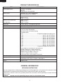
1
SUPPLEMENTAL SERVICE MANUAL
S36M259R1520L
OVER THE RANGE
MICROWAVE OVEN
LIGHT HI/LO
FAN HI/LO
STOP
MODELS
CLEAR
START
MINUTE PLUS
R-1520LK
R-1520LW
R-1520LQ
ThisisasupplementalServiceManualforModelsR-1520LK,R-1520LWandR-1520LQ.ThesemodelsarequitesimilartoBase
ModelR-1500(S/M#S8123R1500X//)andsimilarfeaturesasR-1510/1511(S2205R1510//).
Intheinterestofuser-safetytheovenshouldberestoredtoitsoriginalconditionandonlypartsidenticaltothosespecified
shouldbeused.
WARNINGTOSERVICEPERSONNEL:Microwaveovenscontaincircuitrycapableofproducingveryhighvoltageand
current,contactwithfollowingpartsmayresultinasevere,possiblyfatal,electricalshock.(HighVoltageCapacitor,High
VoltagePowerTransformer,Magnetron,HighVoltageRectifierAssembly,HighVoltageHarnessetc..)
TABLE OF CONTENTS
Page
PRECAUTIONSTOBEOBSERVEDBEFOREANDDURINGSERVICINGTO
AVOIDPOSSIBLEEXPOSURETOEXCESSIVEMICROWAVEENERGY..................... INSIDEFRONTCOVER
BEFORESERVICING....................................................................................................... INSIDEFRONTCOVER
WARNINGTOSERVICEPERSONNEL................................................................................................................. 3
MICROWAVEMEASUREMENTPROCEDURE..................................................................................................... 4
FOREWORDANDWARNING............................................................................................................................... 5
PRODUCTSPECIFICATIONS............................................................................................................................... 6
GENERALINFORMATION.................................................................................................................................... 6
KEYUNIT............................................................................................................................................................... 7
OVENSCHEMATIC................................................................................................................................................ 8
PICTORIALDIAGRAM........................................................................................................................................... 9
PARTSLIST........................................................................................................................................................ 10
PACKINGANDACCESSORIES.......................................................................................................................... 14
SHARP ELECTRONICS CORPORATION
Thisdocumenthasbeenpublishedtobeusedforafter
salesserviceonly.
Thecontentsaresubjecttochangewithoutnotice.
ServiceHeadquarters:SharpPlaza,Mahwah,NewJersey,07430-2135
PRECAUTIONS TO BE OBSERVED BEFORE
AND DURING SERVICING TO AVOID POSSIBLE
EXPOSURE TO EXCESSIVE MICROWAVE
ENERGY
(a) Do not operate or allow the oven to be operated with the door open.
(b) Make the following safety checks on all ovens to be serviced before activating the magnetron or other
microwave source, and make repairs as necessary: (1) interlock operation (2) proper door closing, (3)
seal and sealing surfaces (arcing, wear, and other damage), (4) damage to or loosening of hinges and
latches, (5) evidence of dropping or abuse.
(c) Before turning on microwave power for any service test or inspection within the microwave generating
compartments, check the magnetron, wave guide or transmission line, and cavity for proper alignment,
integrity, and connections.
(d) Any defective or misadjusted components in the interlock, monitor, door seal, and microwave
generation and transmission systems shall be repaired, replaced, or adjusted by procedures described
in this manual before the oven is released to the owner.
(e) A microwave leakage check to verify compliance with the Federal Performance Standard should be
performed on each oven prior to release to the owner.
BEFORE SERVICING
Before servicing an operative unit, perform a microwave emission check as per the Microwave
Measurement Procedure outlined in this service manual.
If microwave emissions level is in excess of the specified limit, contact SHARP ELECTRONICS
CORPORATION immediately @1-800-237-4277.
If the unit operates with the door open, service person should 1) tell the user not to operate the
oven and 2) contact SHARP ELECTRONICS CORPORATION and Food and Drug Administration's
Center for Devices and Radiological Health immediately.
Service personnel should inform SHARP ELECTRONICS CORPORATION of any certified unit
found with emissions in excess of 4mW/cm2. The owner of the unit should be instructed not to use
the unit until the oven has been brought into compliance.
R-1520LK
R-1520LW
R-1520LQ
WARNING TO SERVICE PERSONNEL
Microwave ovens contain circuitry capable of producing very high voltage and current, contact with
following parts may result in a severe, possibly
fatal, electrical shock.
(Example)
High Voltage Capacitor, High Voltage Power
Transformer, Magnetron, High Voltage Rectifier
Assembly, High Voltage Harness etc..
Read the Service Manual carefully and follow all
instructions.
Don't Touch !
Danger High Voltage
When the testing is completed,
1. Disconnect the power supply cord, and then remove
outer case.
2. Open the door and block it open.
3. Discharge high voltage capacitor.
4. Reconnect the leads to the primary of the power
transformer.
5. Reinstall the outer case (cabinet).
6. Reconnect the power supply cord after the outer case
is installed.
7. Run the oven and check all functions.
Before Servicing
1. Disconnect the power supply cord remove outer case.
2. Open the door and block it open.
3. Discharge high voltage capacitor.
, and then
WARNING:RISK OF ELECTRIC SHOCK.
DISCHARGE THE HIGH-VOLTAGE
CAPACITOR BEFORE SERVICING.
The high-voltage capacitor remains charged about 60
seconds after the oven has been switched off. Wait for
60 seconds and then short-circuit the connection of the
high-voltage capacitor (that is the connecting lead of the
high-voltage rectifier) against the chassis with the use of
an insulated screwdriver.
After repairing
1. Reconnect all leads removed from components during
testing.
2. Reinstall the outer case (cabinet).
3. Reconnect the power supply cord after the outer case
is installed.
4. Run the oven and check all functions.
Whenever troubleshooting is performed the power supply must be disconnected. It may, in some cases, be necessary
to connect the power supply after the outer case has been
removed, in this event,
1. Disconnect the power supply cord, and then remove
outer case.
2. Open the door and block it open.
3. Discharge high voltage capacitor.
4. Disconnect the leads to the primary of the power
transformer.
5. Ensure that these leads remain isolated from other
components and oven chassis by using insulation
tape.
6. After that procedure, reconnect the power supply cord.
Microwave ovens should not be run empty. To test for the
presence of microwave energy within a cavity, place a cup
of cold water on the oven turntable, close the door and set the power to HIGH and set the microwave timer for two (2)
minutes. When the two minutes has elapsed (timer at zero)
carefully check that the water is now hot. If the water remains
cold carry out Before Servicing procedure and re-examine
the connections to the component being tested.
When all service work is completed and the oven is fully
assembled, the microwave power output should be checked
and microwave leakage test should be carried out.
R-1520LK
R-1520LW
R-1520LQ
MICROWAVE MEASUREMENT PROCEDURE
A. Requirements:
1) Microwave leakage limit (Power density limit): The power density of microwave radiation emitted by a microwave
oven should not exceed 1mW/cm2 at any point 5cm or more from the external surface of the oven, measured prior to
acquisition by a purchaser, and thereafter (through the useful life of the oven), 5 mW/cm2 at any point 5cm or more
from the external surface of the oven.
2) Safety interlock switches: Primary interlock switch shall prevent microwave radiation emission in excess of the requirement
as above mentioned, secondary interlock relay and door sensing switch shall prevent microwave radiation emission in
excess of 5 mW/cm2 at any point 5cm or more from the external surface of the oven.
B. Preparation for testing:
Before beginning the actual measurement of leakage, proceed as follows:
1) Make sure that the actual instrument is operating normally as specified in its instruction booklet.
Important:
Survey instruments that comply with the requirement for instrumentation as prescribed by the performance standard for
microwave ovens, 21 CFR 1030.10(c)(3)(i), must be used for testing.
2) Place the oven tray in the oven cavity.
o
o
3) Place the load of 275±15 ml (9.8 oz) of tap water initially at 20±5 C (68 F) in the center of the oven cavity.
The water container shall be a low form of 600 ml (20 oz) beaker with an inside diameter of approx. 8.5 cm (3-1/2 in.)
and made of an electrically nonconductive material such as glass or plastic.
The placing of this standard load in the oven is important not only to protect the oven, but also to insure that any leakage
is measured accurately. 4) Set the cooking control on Full Power Cooking Mode.
5) Close the door and select a cook cycle of several minutes. If the water begins to boil before the survey is completed,
replace it with 275 ml of cool water.
C. Leakage test:
Closed-door leakage test (microwave measurement)
1) Grasp the probe of the survey instrument and hold it perpendicular to the gap between the door and the body of the
oven.
2) Move the probe slowly, not faster than 1 in./sec. (2.5 cm/sec.) along the gap, watching for the maximum indication on
the meter.
3) Check for leakage at the door screen, sheet metal seams and other accessible positions where the continuity of the
metal has been breached (eg., around the switches, indicator, and vents).
While testing for leakage around the door pull the door away from the front of the oven as far as is permitted by the
closed latch assembly.
4) Measure carefully at the point of highest leakage and make sure that the highest leakage is no greater than 4mW/cm2,
and that the primary interlock switch does turn the oven OFF before any door movement.
R-1520LK
R-1520LW
R-1520LQ
PRODUCT DESCRIPTION
SUPPLEMENTAL
SERVICE MANUAL
GENERAL INFORMATION
OVER THE RANGE
MICROWAVE OVEN
R-1520LK / R-1520LW / R-1520LQ
OPERATION
FOREWORD
This Manual has been prepared to provide Sharp Electronics Corp.
Service Personnel with Operation and Service Information for the SHARP
MICROWAVE OVENS, R-1520LK, R-1520LW & R-1520LQ.
WIRING DIAGRAM
The models R-1520LK, R-1520LW & R-1520LQ are quite similar to
base model R-1500(Ref.# S8123R1500X//)
PARTS LIST
It is recommended that service personnel carefully study the entire
text of this manual and the base model's manual so that they will be
qualified to render satisfactory customer service.
Check the interlock switches and the door seal carefully. Special attention should be given to avoid electrical shock and microwave radiation
hazard.
WARNING
Never operate the oven until the following points are ensured:
(A) The door is tightly closed.
(B) The door brackets and hinges are not defective.
(C) The door packing is not damaged.
(D) The door is not deformed or warped.
(E) There is no other visible damage with the oven.
Servicing and repair work must be carried out only by trained service
personnel.
DANGER
Certain initial parts are intentionally not grounded and present
a risk of electrical shock only during servicing. Service personnel - Do not contact the following parts while the appliance
is energized;
High Voltage Capacitor, Power Transformer, Magnetron, High
Voltage Rectifier Assembly, High Voltage Harness;
If provided, Vent Hood, Fan assembly, Cooling Fan Motor.
All the parts marked “*” on parts list are used at voltages more
than 250V.
Removal of the outer wrap gives access to voltage above 250V.
SHARP ELECTRONICS CORPORATION
SHARP PLAZA, MAHWAH,
NEW JERSEY 07430-2135
R-1520LK
R-1520LW
R-1520LQ
PRODUCT SPECIFICATION
ITEM
DESCRIPTION
Power Requirements Power Output Case Dimensions Cooking Cavity Dimensions 1.5 Cubic Feet
Hood lamp
Hood fan
Control Complement 120 Volts / 14 Amperes
60 Hertz
Single phase, 3 wire grounded
1000 watts (IEC TEST PROCEDURE)
Operating frequency of 2450MHz
Width 29-15/16"
Height 16-1/4"
Depth 15- 9/16"
Width 17-11/16"
Height 9-7/8"
Depth 14-15/16"
2 bulbs, 20W x 2, Incandescent light bulbs
Approx. 300 C.F.M. (High/Low) Touch Control System
Clock ( 1:00 - 12:59 )
Timer (0 - 99 min. 99 seconds)
Microwave Power for Variable Cooking
Repetition Rate;
P-HI................................................... Full power throughout the cooking time
P-90...................................................................... approx. 90% of Full Power
P-80...................................................................... approx. 80% of Full Power
P-70...................................................................... approx. 70% of Full Power
P-60...................................................................... approx. 60% of Full Power
P-50...................................................................... approx. 50% of Full Power
P-40...................................................................... approx. 40% of Full Power
P-30 . ................................................................... approx. 30% of Full Power
P-20...................................................................... approx. 20% of Full Power
P-10...................................................................... approx. 10% of Full Power
P-0...................................................... No power throughout the cooking time
KEEP WARM pad, POPCORN pad, HOT WATER pad
REHEAT CENTER pads, COOK CENTER pads DEFROST CENTER pads, Number selection pads
POWER LEVEL pad, TIMER / CLOCK pad
LIGHT HI / LO button, FAN HI / LO button,
STOP/CLEAR button, START/ MINUTE PLUS button,
Oven Cavity Light
Safety Standard
Weight
20W x 1 Incandescent light bulb
UL Listed FCC Authorized
DHHS Rules, CFR, Title 21, Chapter 1, Subchapter J
Approx. 55 lbs.
GENERAL INFORMATION
GROUNDING INSTRUCTIONS
This oven is equipped with a three prong grounding plug. It must be plugged into a wall receptacle that is properly installed
and grounded in accordance with the National Electrical Code and local codes and ordinances.
In the event of an electrical short circuit, grounding reduces the risk of electric shock by providing an escape wire for the
electric current.
WARNING:
Improper use of the grounding plug can result in a risk of electric shock.
R-1520LK
R-1520LW
R-1520LQ
LIGHT HI/LO
FAN HI/LO
STOP
CLEAR
START
MINUTE PLUS
NOTE: Someone-touchcookingfeaturessuchas"AddaMinute"aredisabledafterthreeminuteswhentheoven
isnotused.ThesefeaturesareautomaticallyenabledwhenthedoorisopenedandclosedorOFF/CLEAR
buttonispressed.
7
R-1520LK
R-1520LW
R-1520LQ
SCHEMATIC
NOTE: CONDITION OF OVEN
1. DOOR CLOSED.
2. CLOCK APPEARS ON DISPLAY.
NOTE: " " indicates components with potential above 250V.
CAVITY
THERMAL
CUTOUT
BLK
MAGNETRON
TEMPERATURE
FUSE
RED
RED
ORG
RED
BLK
120VAC GND
60Hz
BLK
ORG
BLK
GRN
CONTROL UNIT
RED
RED
N.O.
COM.
RY4
Low
B9
(RY1)
WHT HOOD
MAGNETRON
YLW
TURN
TTM TABLE
MOTOR
MONITOR
SWITCH
FM FAN
MOTOR
WHT
WHT
WHT
OL OVEN
LAMP
WHT
WHT
BRN
RED
ORG
GRY
WHT
WHT
HIGH
VOLTAGE
CAPACITOR
COM.
WHT
HL
WHT
BLU or RED
PNK or
HOOD
LAMP
N.O.
WHT
WHT
RED
B1 B3
GRY
GRY
A3
WHT
WHT
BRN
RED
A1
HL
BLU
AH SENSOR
F2
F3
GND
YLW
F1
RY6
YLW
BLK
WHT
CAPACITOR
E1
(RY2)
SECONDARY
INTERLOCK
RELAY
OVEN LAMP
RELAY
RED
NC
BLK
ORG
BRN
LINE BYPASS CAPACITOR
0.0033 uF 250V
HOOD FAN ORG
THERMAL
High
CUT OUT
B7
WHT
BLU
N
RY5
RY3
POWER
TRANSFORMER
DOOR
SENSING
SWITCH
B5
RED
BLK
A5
HOOD
MOTOR
LINE BYPASS CAPACITOR
0.0033 uF 250V
NOISE SUPRESSION COIL
LINE CROSS CAPACITOR 1.0 uF 275V
WHT
RESISTOR 470 kW 1/2W
L
FUSE
20A
PPL
BLK
E2
PPL
WHT
WHT
WHT
WHT
GRY PRIMARY
NOISE FILTER
INTERLOCK
SWITCH
NOTES:
1.CIRCUITS SUBJECT TO CHANGE WITHOUT NOTICE.
2. TERMINAL WITH PROJECTION OR OPPOSITE BLUE MARK ON LAMP SOCKET
MUST BE CONNECTED TO NEUTRAL WIRE.
3. ONLY CERTAIN MODELS USE THE ABSOLUTE HUMIDITY SENSOR.
4. POWER TRANSFORMER LEFT (FINISH LEAD) TERMINAL MUST BE CONNECTED TO THE NEUTRAL (WHITE) WIRE.
Figure O-1. Oven Schematic-Off Condition
CAVITY
THERMAL
CUTOUT
NC
WHT
E1
F1
AH SENSOR
MONITOR
SWITCH
FM FAN
MOTOR
WHT
WHT
GRY PRIMARY
INTERLOCK
SWITCH
WHT
WHT
TURN
TTM TABLE
MOTOR
WHT
WHT
OL OVEN
LAMP
RED
BRN
ORG
BRN
ORG
WHT
WHT
WHT
HIGH
VOLTAGE
CAPACITOR
COM.
GRY
GRY
GRY
BLU or RED
HL
WHT
WHT
RED
BRN
N.O.
PNK or
HOOD
LAMP
WHT
WHT
B1 B3
WHT
WHT
RED
YLW
A3
WHT
NOTES:
1.CIRCUITS SUBJECT TO CHANGE WITHOUT NOTICE.
2. TERMINAL WITH PROJECTION OR OPPOSITE BLUE MARK ON LAMP SOCKET
MUST BE CONNECTED TO NEUTRAL WIRE.
3. ONLY CERTAIN MODELS USE THE ABSOLUTE HUMIDITY SENSOR.
4. POWER TRANSFORMER LEFT (FINISH LEAD) TERMINAL MUST BE CONNECTED TO THE NEUTRAL (WHITE) WIRE.
Figure O-2. Oven Schematic-Cooking Condition
MAGNETRON
F2
F3
A1
HL
BLU
RY6
YLW
BLK
CAPACITOR
GND
YLW
(RY2)
SECONDARY
INTERLOCK
RELAY
OVEN LAMP
RELAY
(RY1)
WHT HOOD
POWER
TRANSFORMER
DOOR
SENSING
SWITCH
RY5
RY3
Low
B9
E2
RED
BLK
LINE BYPASS CAPACITOR
0.0033 uF 250V
HOOD FAN ORG
THERMAL
High
CUT OUT
B7
BLK
COM.
RY4
B5
WHT
BLU
NOISE FILTER
A5
N.O.
RED
PPL
HOOD
MOTOR
LINE BYPASS CAPACITOR
0.0033 uF 250V
NOISE SUPRESSION COIL
LINE CROSS CAPACITOR 1.0 uF 275V
RESISTOR 470 kW 1/2W
FUSE
20A
PPL
BLK
CONTROL UNIT
N
RED
RED
BLK
ORG
120VAC GND
60Hz
WHT
RED
ORG
RED
BLK
BLK
GRN
L
MAGNETRON
TEMPERATURE
FUSE
RED
WHT
BLK
SCHEMATIC
NOTE: CONDITION OF OVEN
1. DOOR CLOSED.
2. COOKING TIME PROGRAMMED.
3. VA R I A B L E C O O K I N G C O N T RO L
"HIGH".
4. "START" button pressed.
H
1
2
3
14
4
BLU
T1
1
2
CN-E
CN-C
CN-C
1
C100
BLK
PPL
CN-B
9
1
CN-A
5
RY2: SECONDARY INTERLOCK RELAY
COM.
N.O.
N.O.
COM.
CN-G
RY2:
NOISE FILTER
BOARD
CONTROL UNIT
WHT
WHT
BLK
G
N
H
AH SENSOR
BRN
PNK OR RED
OR BLU
YLW
4
3
5
to Right Base Plate
RED
RED
BLK
ORG
GRY
GRY
WHT
WHT
1 RED
2
PPL
5
CN-A
1
2
4
3
5
CN-E
2 GRN
1 RED
RED
N.O.
COM.
WHT
WHT
WHT
GRY
WHT
TURNTABLE
MOTOR
BLU
WHT
BRN
BLK
RED
WHT
BRN
WHT
FAN
MOTOR
RED
CAVITY
THERMAL
CUT-OUT
1 BLU
RED 5 RED
YLW 4 YLW
WHT 3 WHT
BLK 2 BLK
HOOD FAN MOTOR
BLK
3 BLK
GRY
BRN
ORG
Power Supply
cord 120V 60Hz
MAGNETRON
TEMPERATURE
FUSE
RED
Blue Marking
HOOD LAMPS
& SOCKETS
W
H
T
W
H
T
R
E
D
PNK OR RED
OR BLU
WHT
WHT
MAGNETRON
ORG
BLK
HIGH
VOLTAGE
RECTIFIER
HOOD FAN
THERMAL
CUT-OUT
POWER
TRANSFORMER
HIGH VOLTAGE
WIRE A
HIGH VOLTAGE
CAPACITOR
HIGH VOLTAGE COMPONENTS
BLK
RED
OVEN LAMP & SOCKET
Blue
Marking
WHT 2 WHT
GRN 1 GRN
5
6
Figure S-1. Pictorial Diagram
PRIMARY
INTERLOCK
SWITCH
COM.
MONITOR
SWITCH
N.C.
RED
N.O.
GRN
COM.
DOOR SENSING SWITCH
GRN
6
4
RY2
COM.
RY2
N.O.
RY1
COM.
RY1
N.O.
BLK
ORG
8
7
6
WHT
9
CN-B
to Chassis Support
F
RY3
B
RY4
E
3
RY5
D
2
RY6
1
RY1
CN-F
1 BLK
2 RED
3 WHT
R-1520LK
R-1520LW
R-1520LQ
6
A
A
B
C
C
D
E
F
G
H
R-1520LK
R-1520LW
R-1520LQ
PARTS LIST
Note:The parts marked “∆” may cause undue microwave exposure.
The parts marked “*” are used in voltage more than 250V.
REF. NO.
*
*
*
∆*
"§" mark: Parts Delivery Section
PART NO.
§
DESCRIPTION
Q'TY CODE
1- 1
1- 2
1- 3
1- 4
1- 5
1- 6
1- 7
1- 8
1- 9
1-10
1-11
1-12
1-13
1-14
1-15
1-16
1-17
FH-DZB016MRY0
RC-QZA186WRZZ
QFS-TA013WRE0
RMOTDA264WRZZ
RTHM-A070WRE0
RTHM-0044MRE0
RTRN-B086MRE0
RV-MZA288WRE0
FPWBFA380WRKZ
QSW-MA085WRE0
FFS-BA016/KIT
FACCDB011MRE0
QSOCLB006MRE0
FMOTEA489WRKZ
RMOTEB031MRE0
RLMPTA086WRZZ
FDTCTA201WRK0
M
M
M
M
M
M
M
M
M
M
M
M
M
M
M
M
M
2- 1
2- 2
2- 2
2- 2
2- 3
2- 4
2- 4
2- 4
2- 5
2- 5
2- 5
2- 6
2- 7
2- 7
2- 7
2-7-1
2-7-1
2-7-1
2-7-2
2- 8
2- 8
2- 8
LSTY-B026MRP0 M
PDIF-B058MRF0 M
PDIF-B059MRF0 M
PDIF-B060MRF0 M
GDAI-B065MRP0A M
HDECQB082MRF0 M
HDECQB083MRF0 M
HDECQB084MRF0 M
GCABUB103MRP0 M
GCABUB105MRP0 M
GCABUB110MRP0 M
TMAPCB098MRR0 M
FANGKB009MRY0 M
FANGKB010MRY0 M
FANGKB013MRY0 M
LANGQB016MRP0 M
LANGQB020MRP0 M
LANGQB049MRP0 M
PGLSPB004MRE0 M
PCOVPB096MRT0 M
PCOVPB097MRT0 M
PCOVPB102MRT0 M
Rear stay
Hood exhaust louver (R-1520LK)
Hood exhaust louver (R-1520LW)
Hood exhaust louver (R-1520LQ)
Base plate R Front panel L (R-1520LK) Front panel L (R-1520LW) Front panel L (R-1520LQ) Outer case cabinet (R-1520LK)
Outer case cabinet (R-1520LW)
Outer case cabinet (R-1520LQ)
Schematic diagram
Hood lamp glass assembly (R-1520LK)
Hood lamp glass assembly (R-1520LW)
Hood lamp glass assembly (R-1520LQ)
Hood lamp glass angle (R-1520LK)
Hood lamp glass angle (R-1520LW)
Hood lamp glass angle (R-1520LQ)
Hood lamp glass
Base cover (R-1520LK)
Base cover (R-1520LW)
Base cover (R-1520LQ)
333333333333333333-
1
2
2
2
3
3
3
4
4
4
5
5
5
6
7
8
9
10
CPWBFB076MRU0
HPNLCB217MRR0
HPNLCB218MRR0
HPNLCB220MRR0
FUNTKB458/KIT
FUNTKB459/KIT
FUNTKB460/KIT
JBTN-B195MRF0
JBTN-B197MRF0
JBTN-B199MRF0
JBTN-B196MRF0
JBTN-B198MRF0
JBTN-B200MRF0
MSPRTA045WRE0
LHLD-B018MRF0
PSHEPB023MRE0
XEPS730P08XS0
LANGQB080MRP0
M
M
M
M
M
M
M
M
M
M
M
M
M
M
M
M
M
M
Control unit Control panel sub. assembly
Control panel sub. assembly
Control panel sub. assembly
Key unit
(R-1520LK)
Key unit
(R-1520LW)
Key unit
(R-1520LQ)
Open button (R-1520LK)
Open button (R-1520LW)
Open button (R-1520LQ)
Select button (R-1520LK) Select button (R-1520LW) Select button (R-1520LQ) Button spring
LCD holder
LED sheet
Screw; 3mm x 10mm
Key fixing angle 4444-
1
2
3
4
LSTPPB038MRF0
FROLPB025MRK0
NTNT-A108WREZ
LBNDKB009MRP0
M
M
M
M
Door stopper
Turntable support assembly
Turntable tray
Capacitor holder
ELECTRIC PARTS
High voltage rectifier assembly High voltage capacitor
Temperature fuse 150oC (Magnetron)
Turntable motor
Thermal cut-out 145oC (Cavity) Thermal cut-out N.O. 60oC (Hood Fan)
Power transformer
Magnetron
Noise filter unit
Primary interlock and door sensing switches Monitor switch (V-16G-2C25) with fuse (20A) assembly
Power supply cord Oven lamp socket Hood fan motor
Fan motor
Oven lamp AH sensor
1
1
1
1
1
1
1
1
1
2
1
1
3
1
1
3
1
AT
AL
AE
AG
AF
AH
BA
BK
AM
AE
AF
AQ
AE
BB
AR
AD
AR
1
1
1
1
1
1
1
1
1
1
1
1
1
1
1
1
1
1
1
1
1
1
AF
AS
AW
AS
AG
AG
AM
AG
AZ
AZ
AZ
AB
AN
AM
AM
AG
AG
AG
AH
AV
AV
AQ
1
1
1
1
1
1
1
1
1
1
1
1
1
1
1
1
4
1
BE
AM
AM
AM
AP
AP
AP
AM
AH
AH
AC
AC
AC
AA
AC
AR
AB
AM
1
1
1
1
AB
AN
AM
AB
CABINET PARTS
CONTROL PANEL PARTS
(R-1520LK) (R-1520LW) (R-1520LQ) OVEN PARTS
10
R-1520LK
R-1520LW
R-1520LQ
REF. NO.
4- 5
4- 6
4- 7
4- 8
4- 9
4-10
4-11
4-12
4-13
4-14
4-15
4-16
4-17
4-18
4-19
4-20
4-21
4-22
4-23
4-24
4-25
5555555555555-
1
2
2
2
3
4
5
6
7
8
9
9
10
PART NO.
PDUC-B111MRF0
MLEVPB016MRF0
*************
PPACGB014MRF0
PHOK-B018MRF0
FANGTB005MRY0
NFANPB006MRE0
LBSHC0037WRE0
MLEVFB007MRP0
PDUC-B112MRP0
PCOVPB085MRP0
MSPRTA046WRE0
LANGTB055MRP0
PDUC-B115MRF0
PDUC-B114MRF0
PDUC-B113MRP0
PDUC-B117MRF0
PCUSGB043MRP0
PCUSUB045MRP0
PCUSUB019MRP0
PCUSUB061MRP0
§
M
M
M
M
M
M
M
M
M
M
M
M
M
M
M
M
M
M
M
M
M
DESCRIPTION
Magnetron duct Open lever Oven cavity (Not replaceable part)
Turntable motor packing Latch hook
Unit mounting plate assembly Fan blade Cord bushing
Mounting lever Hood intake duct R Waveguide cover Latch spring Chassis support
Hood duct R
Hood duct L
Fan duct Orifice Transformer cushion
Cushion
Cushion
Cushion
DOOR PARTS
FDORFB086MRT0 M
GWAKPB223MRR0A M
GWAKPB224MRR0A M
GWAKPB225MRR0 M
LSTPPB021MRF0 M
MSPRTA046WRE0 M
LSTPPB054MRF0 M
GCOVHB044MRF0 M
PSHEPB016MRE0 M
XCPS740P08000 M
PGLSPB112MRE0 M
PGLSPB113MRE0 M
GMADIB041MRF0A M
Door panel assembly
Door frame assembly (R-1520LK)
Door frame assembly (R-1520LW)
Door frame assembly (R-1520LQ)
Latch head
Latch spring Glass stopper
Choke cover
Sealer film Screw : 4mm x 8mm
Door glass (R-1520LK)
Door glass (R-1520LW, R-1520LQ)
Display window
6- 1
6-1-1
6-1-2
6-1-3
6-1-4
6-1-5
6-1-6
6- 2
6- 3
6- 4
6- 5
6- 6
6- 7
6- 8
6- 9
6-10
6-11
6-12
6-13
6-14
6-15
6-16
6-17
CFZK-B460MRK0
LBSHC0040MRE0
LX-BZ0195WRE0
XBRS750P60000
XOTS740P12000
XTSS750P35000
XWHS750-16300
TINSKB108MRR0
TINSEB446MRK0
QW-QZB025MRE0
FW-VZB284MRE0
TCAUAB055MRR0
TCAUAB050MRR0
TCAUAB048MRR0
FW-VZB189MRE0
PFIL-B006MRE0
PFIL-B002MRE0
FFTA-B005MRK0
PCUSUB059MRP0
LANGQB025MRP0
QW-VZB011MRE0
LANG-B002MRP0
TINSEB450MRR0
M
M
M
M
M
M
M
M
M
M
M
M
M
M
M
M
M
M
M
M
M
M
M
Installation material assembly
Grommet
Toggle screw Screw : 5mm x 60mm Screw : 4mm x 12mm Screw : 5mm x 35mm Washer
Top/wall template
Operation manual High voltage wire A Main harness
DHHS service caution label Monitor caution label Revised DHHS/GRD C/label Low voltage harness
Charcoal filter
Grease filter
Exhaust damper assembly
Cushion (only for horizontal venting)
Noise unit angle
Sensor ground wire
Scale plate Installation instructions
7777777777-
LX-CZB004MRE0
LX-CZB016MRE0
XOTSF40P12000
XOTS740P12000
XHTS740P08RV0
LX-CZ0052WRE0
XCBS730P08000
XCPS730P08000
LX-BZA041WRE0
LX-WZA003MRE0
M
M
M
M
M
M
M
M
M
M
Special
Special
Screw :
Screw :
Screw :
Special
Screw :
Screw :
Special
Washer
Q'TY CODE
1
AF
1
AD
1
-1
AA
1
AF
1
AS
1
AC
1
AB
2
AC
1
AG
1
AH
2
AB
2
AD
1
AQ
1
AQ
1
AH
1
AC
1
AC
1
AC
1
AC
1
AC
1
1
1
1
1
1
2
1
1
2
1
1
1
AV
AT
AT
AT
AD
AB
AC
AG
AE
AA
AS
AS
AB
1
1
4
2
3
6
2
1
1
1
1
2
1
1
1
1
2
1
1
1
1
2
1
AH
AC
AC
AA
AA
AA
AA
AD
AD
AT
AV
AA
AA
AB
AT
AE
AF
AH
AC
AE
AB
AD
AD
3
3
4
36
2
2
2
2
5
1
AA
AA
AA
AA
AA
AA
AA
AA
AA
AA
MISCELLANEOUS
1
1
2
3
4
5
6
7
8
9
SCREWS,NUTS AND WASHERS
screw
screw
4mm x
4mm x
4mm x
screw
4mm x
4mm x
screw
(R-1520LK)
(R-1520LW, R-1520LQ)
12mm 12mm
8mm
8mm
8mm
11
R-1520LK
R-1520LW
R-1520LQ
2
1
4
3
6
5
OVEN AND CABINET PARTS
A
A
6-1-5
6-12
4-10
6-15
7-3
2-1
7-7
7-3
B
7-9
1-17
B
7-3
7-3
2-5
7-3
7-5
4-12
1-12
7-3
4-19
7-3
1-14
C
C
4-24
7-3
7-3
4-23
4-17
4-16
D
2-6
7-3
7-3
4-18
4-13
4-17
6-14
7-7
7-5
2-2
7-3
4-7
6-8
6-10
1-3
7-3
4-16
E
1-15
4-20
4-13
7-1
4-15
6-7
7-5
4-8
6-6
F
4-3
4-25
1-4
1-16
1-7
1-11
1-5
2-8
1-16
1-1
4-9
1-10
1-10
7-6
7-8
7-4
4-11
1-8
1-2
E
4-4
4-5
7-6
4-6
D
1-9
6-13
2-4
1-11
7-8
1-13
F
4-21
4-14
4-22
1-6
1-13
7-3
4-2
G
G
2-3
7-3
7-3
7-2
7-3
7-2
6-11
2-7-2
6-11
2-7
H
H
2-7-1
7-2
1
2
4
3
12
5
6
R-1520LK
R-1520LW
R-1520LQ
2
1
4
3
3-9
3-7
A
6
5
A
3-8
CONTROL PANEL PARTS
3-1
3-3
3-9
3-9
3-2
B
B
DOOR PARTS
4-1
3-10
7-3
C
C
3-5
5-6
3-4
5-7
3-6
5-8
5-1
D
D
5-5
5-8
5-2
5-5
5-10
E
E
5-3
5-4
6-4
5-9
F
F
6-5
MISCELLANEOUS
6-1
6-1-1
6-1-4
G
G
6-1-5
6-1-2
6-9
6-1-6
6-1-3
H
H
1
2
4
3
13
5
6
R-1520LK
R-1520LW
R-1520LQ
HOW TO ORDER REPLACEMENT PARTS
To have your order filled promptly and correctly, please furnish the following information.
1. MODEL NUMBER
2. REF. NO.
3. PART NO.
4. DESCRIPTION
Order Parts from the authorized SHARP parts Distributor for your area.
Defective parts requiring return should be returned as indicated in the Service Policy.
PACKING AND ACCESSORIES
6-16 SCALE PLATE (x 2)
4-3 TURNTABLE TRAY
6-11 GREASE FILTER (x 2)
TOP PAD
6-2 TOP / WALL TEMPLATE
6-3
OPERATION MANUAL
6-17 INSTALLATION INSTRUCTION
DOOR PROTECTOR
6-1 INSTALL MATERIAL ASSEMBLY
WRAP COVER
6-12 EXHAUST DAMPER
ASSEMBLY
ACCESSORY PACK
DOOR PAD
BOTTOM PAD
Non-replaceable items
PACKING CASE
14
R-1520LK
R-1520LW
R-1520LQ
NOTES
15
R-1520LK
R-1520LW
R-1520LQ
COPYRIGHT © 2006 BY SHARP CORPORATION
ALL RIGHTS RESERVED.
No part of this publication may be reproduced,
stored in retrieval systems, or transmitted
in any form or by any means, electronic,
mechanical, photocopying, recording, or
otherwise, without prior written permission
of the publisher.
2006 SHARP CORP. (2M2.20E) Printed in U.S.A
16