1
INSTALLATION
26/1531-ANF
22
01
2014
E10
901INSTRUCTIONS
14
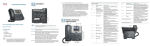
Aastra 6700i SIP Terminals for
MX-ONE
Arne Miler
Amiler
amiler
INSTALLATION INSTRUCTIONS
AASTRA 6700I SIP TERMINALS FOR MX-ONE
Copyright
© Copyright Aastra Technologies Limited, 2014. All rights reserved.
Disclaimer
No part of this document may be reproduced in any form without the
written permission of the copyright owner.
The contents of this document are subject to revision without notice due
to continued progress in methodology, design and manufacturing.
Aastra shall have no liability for any error or damage of any kind resulting
from the use of this document.
2
26/1531-ANF 901 14 Uen E10 2014-01-22
GENERAL
1
General
This document is valid for Aastra 6730i, 6731i, 6735i, 6737i, 6739i,
6753i, 6755i and 6757i SIP phones, when installing these telephones in
a MX-ONE environment.
1.1
Scope
This document describes how to install and configure for the Aastra
6700i terminals in a MX-ONE Telephony Server (TSE) environment. For
general installation information that is not unique for a MX-ONE environment, there is a reference to the Administrator Guide for Aastra Models
6700i and 9000i Series IP SIP Phones.
There is also one platform independent installation guide per telephone
model available on www.aastra.com.
1.2
Glossary
Some expressions in this document follows the expressions used in
MX-ONE, which can differ from the expressions used in the Administrator Guide for Aastra Models 6700i and 9000i Series IP SIP Phones.
Table 1 Expressions used in MX-ONE and in 6700i documents
MX-ONE
Administrator Guide for Aastra
Models 6700i and 9000i Series IP
SIP Phones
Software server
Configuration server
Shortcut keys
Programmable keys and Softkeys
TNS (Telephony Name
Selection)
Speed dial
MNS (Monitored extensions)
BLF (Busy Lamp Field)
Settings key
Options key
Key Panel Unit (KPU) and
Display Panel Unit (DPU)
Expansion Module
26/1531-ANF 901 14 Uen E10 2014-01-22
3
AASTRA 6700I SIP TERMINALS FOR MX-ONE
1.3
Environmental Requirements
See Administrator Guide for Aastra Models 6700i and 9000i Series IP
SIP Phones.
4
26/1531-ANF 901 14 Uen E10 2014-01-22
CABLING
2
Cabling
See Administrator Guide for Aastra Models 6700i and 9000i Series IP
SIP Phones.
26/1531-ANF 901 14 Uen E10 2014-01-22
5
AASTRA 6700I SIP TERMINALS FOR MX-ONE
3
Power Equipment
These telephones can be powered from any of the following methods:
•
6730i is powered from an AC adapter 5V. No PoE support.
•
6731i, 6735i, 6737i, 6739i, 6753i, 6755i, 6757i are powered using
PoE according to IEEE 802.3af or from an AC/DC adapter 48 V.
•
Power over Ethernet power injector, which supplies 48 V power
through the Ethernet cable on pins 4&5 and 7&8. The power
injector is available as an optional accessory.
Table 2 Power classes for the different phone models
Device
Power Consumption **)
Power Class
6730i
2.4 W
not applicable
6731i
2.4 W
1
6735i
2.8 W
2 *) from REV:29
6737i
2.9 W
2 *) from REV:30
6739i
4.8 W
0
6753i
3.3 W
0
6755i
4.0 W
0
6757i
4.1 W
0
*) Maximum one expansion module with PoE. Up to three modules with
AC/AC adapter.
**) Single call established in handset mode, backlight on. No PC
connected.
Explanation of power classes:
6
•
0 - classification is not implemented.
•
1 - less than 3.84 W.
•
2 - less than 6.49 W.
26/1531-ANF 901 14 Uen E10 2014-01-22
EARTHING AND GROUNDING
4
Earthing and Grounding
See Administrator Guide for Aastra Models 6700i and 9000i Series IP
SIP Phones.
26/1531-ANF 901 14 Uen E10 2014-01-22
7
AASTRA 6700I SIP TERMINALS FOR MX-ONE
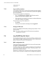
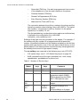
5
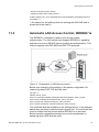
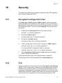
Setting up the Software Server
The software and the configuration files used by the IP phones shall be
stored on a server where the IP phones can fetch them. The server is
called IP Phone SW Server.
Manager Telephony System
Telephony
Server
IP Phone
SW Server
IP Phone
SW Server
Telephony Domain B
IP Phone SW Server
Application installed
Telephony Domain A
Figure 1: Deployment Scenario when telephony domains use different
SW servers
In the Telephony Server you can define multiple telephony domains. The
telephony domains are managed through the Manager Telephony
System web interface.
The IP phone configuration files are preferably generated through the
Manager Telephony System (MTS). To enable the files to be generated
through Manager Telephony System, the IP Phone SW Server Configuration Management Application must be installed on the IP Phone SW
Server. Once generated the configuration files can viewed directly on the
IP Phone SW Server.
The IP phones can use the following protocols to download the software
and configuration file(s): http, https, ftp, tftp. The recommendation is to
use the http protocol and it is described in these installation instructions.
If MTS for some reason is not used, stop reading and go to chapter “How
to start a new phone”.
Setting up the software server comprises the following steps:
•
8
Installing the IP Phone SW Server Configuration Management
Application.
26/1531-ANF 901 14 Uen E10 2014-01-22
SETTING UP THE SOFTWARE SERVER
5.1
•
Reconfigure Microsoft IIS web server, if it exists.
•
Creating a directory structure on the IP Phone SW Server.
•
Copy the IP phone application and language files to the IP Phone
SW Server. The configuration files shall not be copied, these are
created by MTS. For information about the files, see section 8.1
Phone software and configuration files on the software server on
page 24.
Install IP Phone SW Server
Before the installation of the IP Phone SW Server you have to install the
Java Runtime Enviroment. When you run IP Phone SW Server wizard
the Tomcat is also installed.
Note: For more information see the IP Phone SW Server release notes
for additional installation information. See also section 8.1 Phone software and configuration files on the software server on page 24 on how
to manage the SW in the IP phone.
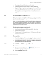
5.1.1
5.1.2
5.1.3
System and program requirements
•
Java Runtime Enviroment (JRE) version 6 (32- bit) or later.
•
Windows 32 bit or 64 bit.
•
Tomcat version 7.0.33 (apache-tomcat-7.033-windows x86.zip), is
installed via the wizard.
Prerequisites
•
Check if Java Runtime Enviroment version 6 or later, is installed. If
not, installed JRE before you start the IP Phone SW Server wizard.
•
If IP Phone Server (version 1.4 or prior) is installed, uninstalled the
the program before you start the wizard.
Install IP Phone SW Server (and Tomcat)
Do as follows:
1.
Download and click Setup.exe,
Installer Language is displayed.
2.
Select Language from the list.
26/1531-ANF 901 14 Uen E10 2014-01-22
. The window
9
AASTRA 6700I SIP TERMINALS FOR MX-ONE
3.
Click OK. The window Welcome to the IPPhone SW Server
Setup Wizard is displayed.
4.
Click Next. The step Licence Agreement is displayed.
5.
Click Agree. The step Tomcat Port Number is displayed.
6.
Type the port number in the field, default port is 80.
7.
Click Next. The step Tomcat Administrator is displayed.
8.
Click Next.
9.
The message window, Do you want to continue without configuring a Tomcat administrator? is displayed.
10. Click Yes. The step Choose Install Location is displayed.
11. Click Install. When the installation is complete you will get a
message, Installation Complete.
12. Click Next. The step Completing the IPPhone SW Server Setup
Wizard is displayed.
13. Click Finish.
5.2
Co-existence with Microsoft IIS Web Server
If a Windows IIS web server is running on the IP Phone SW Server there
will be a port conflict with the IP Phone SW Server Configuration
Management Application since they are both using port 80. This is typically the case when CMG or OneBox are installed on the same server.
10
26/1531-ANF 901 14 Uen E10 2014-01-22
SETTING UP THE SOFTWARE SERVER
The reason that you need to have the Tomcat web server running
instead of just using the IIS web server is that the IP Phone SW Server
Configuration Management Application is developed in Java and IIS can
only host web applications developed in the Microsoft environment.
Perform the following steps to resolve the port conflict.
•
Keep IIS running on port 80.
•
Reconfigure the IP Phone Configuration Management Application
to run on port 82 instead.
–
Edit the jakarta-tomcat-4.1.31\conf\server.xml (where
-4.1.31 is an example) and change the port 80 to 82.
–
Restart Tomcat by going to
Control Panel/Administrative Tools/Services
Restart the service Jakarta Tomcat 4.
•
Connect MTS to IP Phone SW Server Configuration Management
Application on port 82, using the MTS task IP Phone SW Server.
•
Create the configuration file in the MTS task IP Phone configuration
File and it will be stores on the IP Phone SW Server, see section
6.1 Create a Configuration File on page 15 for details.
•
The .cfg, .st, .txt and .tuz file types must be enabled. Follow the
steps below to enable these file types:
•
–
In IIS Manager, select File Type, select DefaultWEB Site.
–
Select Properties and edit HTTP header. Apply the following
settings:
–
Associated extension: .cfg, .st, .txt and .tuz (encrypted .cfg
file)
–
Content type (MIME): application/octet-stream.
Redirect IIS web server to Tomcat web server for the IP phone’s
requests like this:
26/1531-ANF 901 14 Uen E10 2014-01-22
11
AASTRA 6700I SIP TERMINALS FOR MX-ONE
12
–
Open C:\WINDOWS\system32\inetsrv\inetmgr.exe, navigate
to Default Web Site.
–
Right click on Default Web Site and select New Virtual Directory. A wizard will start.
–
Enter the directory name to where the telephone firmware
shall be stored as Alias, example: aastra67xxi.
–
Enter the path to the folder under Tomcat, example:
C:\jakarta-tomcat-4.1.31\webapps\ROOT\aastra67xxi.
–
Enable the Read option and finish the wizard.
–
You can now access the Tomcat folder with terminal settings
on both port 80 as well as 82, while MTS can update the
configuration file on port 82.
–
If subnets or telephony domains are defined for the configuration file in MTS, the path under Tomcat will include the
subnet/telephony domain in its path. Update the IIS virtual
directory link accordingly.
26/1531-ANF 901 14 Uen E10 2014-01-22
SETTING UP THE SOFTWARE SERVER
5.3
Start of the Tomcat Web Server
During the installation of IP Phone SW Server Configuration Management Application for Windows®, Tomcat will start automatically on port
80. In case Tomcat is not up and running, it can be started manually with
Windows® Services Jakarta Tomcat 4 (see instruction below) or by
restarting the Tomcat web server PC.
If the Tomcat web server starts on another port number than 80, the port
number can be set manually in the file
jakarta-tomcat-4.1.31\conf\server.xml (where -4.1.31 is an example).
5.3.1
Verify that the Apache Tomcat server is running
Use the following procedure on the server PC:
1.
Go to Control Panel/ Administrative Tools/
Services
Check that the service Jakarta Tomcat 4 has status started. If the
service has not been automatically started, then start it manually.
2.
Start a web browser for example Internet Explorer and enter the
address http://localhost. The Apache Tomcat web page
server is shown.
3.
Enter the address http://localhost/ipfmsBinary in the
web browser.
The Axis web page is shown.
26/1531-ANF 901 14 Uen E10 2014-01-22
13
AASTRA 6700I SIP TERMINALS FOR MX-ONE
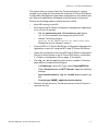
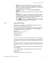
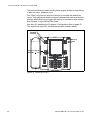
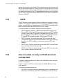
6
Manage the Configuration Files in
Manager Telephony System
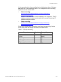
MX-ONE Manager Telephony System (MTS) shall be used when
creating or changing the aastra.cfg and the model specific configuration
files. The information regarding parameters is available in the online help
for MX-ONE Manager Telephony System. The picture below shows an
example of the page in the IP Phone Configuration File task in MTS:
Figure 2: IP Phone Configuration File in Manager Telephony System
Note: MTS requires that the IP Phone SW Server Configuration
Management Application is installed on the IP Phone SW Server,
please see section 5 Setting up the Software Server on page 8
14
26/1531-ANF 901 14 Uen E10 2014-01-22
MANAGE THE CONFIGURATION FILES IN MANAGER TELEPHONY SYSTEM
6.1
Create a Configuration File
The procedure to create a new configuration file is:
•
Log in to MX-ONE Manager Telephony System.
•
Go to Telephony > IP Phone > Configuration file. Press Add
new to open the new configuration file.
Make sure that Aastra 67xxi family is selected and enter the data
into the configuration file which is automatically stored under the
correct directory in the IP Phone Software Server when pressing
Apply.
•
6.2
To force the telephones to fetch the new configuration file there are
a number of cases:
–
If the telephones are not started yet: connect the power and
the telephones will fetch the new configuration file.
–
If the telephones are already registered to the PBX, select the
Unregistration option to force the telephones to fetch the
new configuration file.
–
The telephones will after less than 24 hours automatically
fetch the new configuration file and if necessary download a
new firmware.
–
Restart the telephones manually.
Changing an Existing Configuration File
The existing configuration file can be updated using the MX-ONE
Manager Telephony System.
The following procedure shall be used when the configuration file shall
be changed:
1.
Log in to MX-ONE Manager Telephony System and select:
Telephony > IP Phone > Configuration file
2.
Take a backup copy of the existing configuration file by pressing the
backup icon.
3.
Use the Change icon to view the configuration file. When the adaptation of the file is completed, it is automatically stored under the
aastra67xxi directory in the IP Phone Software Server.
4.
For the telephones that are already registered to the PBX, select
the Unregistration option to force the telephones to fetch the new
26/1531-ANF 901 14 Uen E10 2014-01-22
15
AASTRA 6700I SIP TERMINALS FOR MX-ONE
configuration file. For the not registered telephones, see section 6.1
Create a Configuration File on page 15.
6.3
Scratch Pad when Creating the Configuration file
If a new parameter has to be added into the aastra.cfg file but there is no
support for this new parameter in Manager Telephone System, the
scratch pad can be used. Another usage is if MTS creates a parameter
value, but another value is requested.
It is a free text window where the new parameter or parameter value can
be entered. The parameters are added at the end of the aastra.cfg file.
If a parameter exists twice in the configuration file, the telephone uses
the value at the end of the file.
The scratch pad is found at the bottom of the page:
Telephony > IP Phone > Configuration File > General Setting
6.4
Connect Existing Configuration File to
Manager Telephony System
In a system where MX-ONE Manager Telephony System has not previously been used when working with an IP phone configuration file, the
existing configuration file can be connected to the MTS instead of having
to be recreated. Follow the steps below to connect a configuration file to
MX-ONE Manager Telephony System.
16
1.
Log on to MX-ONE Manager Telephony System.
2.
Go to Telephony > IP Phone > SW Server where you register the
IP Phone SW Server.
3.
Go to Telephony > IP Phone > Connect Configuration File.
4.
Select the IP Phone SW Server and search for existing files. Click
on the Connect icon next to the configuration file to connect to.
5.
Go to the Configuration File task. Select the connected configuration file and use the Change icon to change the file, if needed.
When the adaptation of the file is completed, it is automatically
stored under the correct directory in the IP Phone Software Server.
6.
For the phones that are already registered to the PBX, select the
Unregistration option to force the phones to fetch the new configuration file.
26/1531-ANF 901 14 Uen E10 2014-01-22
MANAGE THE CONFIGURATION FILES IN MANAGER TELEPHONY SYSTEM
6.5
Retrieve the Back-up Copy
If any problem is discovered when a new configuration file has been
loaded into the phones and there is a need to go back to the previous
version, the following procedure shall be used:
1.
Log on to MX-ONE Manager Telephony System.
2.
Go to Telephony > IP Phone > Configuration File.
3.
Use the back-up retrieve icon.
4.
For the phones that are already registered to the PBX, select the
Unregistration option to force the phones to fetch the new
configuration file. For phones that are not registered, 6.1 Create a
Configuration File on page 15.
26/1531-ANF 901 14 Uen E10 2014-01-22
17
AASTRA 6700I SIP TERMINALS FOR MX-ONE
7
How to Start a New Phone
The phone is delivered with default settings for an IP network. These
settings must be adapted to the local network using phone configuration
files.
If Manager Telephony Server (MTS) is used and chapter 5.1 Install IP
Phone SW Server on page 9 has been followed, the phone configuration
files are generated and stored on the Software Web Server.
If MTS is not used, a software server must be set up supporting any of
the protocols HTTP or HTTPS to host the phone firmware, language files
and configuration files. The firmware files can be downloaded from
Service Support Plaza. There are phone configuration template files
adapted for MX-ONE stored under: etc/opt/eri_sn/aastraSIPPhone.
All firmware files are described in section 8.1 Phone software and configuration files on the software server on page 24.
When the phone is powered up, it will look for software (firmware) and
configuration files on the software server according to its configuration
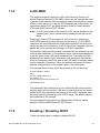
server settings, see section11.8 Setting the IP Address and Download
Protocol of the Software Server on page 34.
18
26/1531-ANF 901 14 Uen E10 2014-01-22
HOW TO START A NEW PHONE
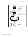
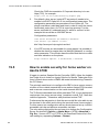
7.1
Boot flow chart
Power up
To get access to the LAN
802.1x
To get Voice VLAN
LLDP
:Configuration of:
-IP address, mask W
-DNS servers
-Time server
-Time zone ofst
-Software server URI (opt 66,43)
DHCP
SW-server configured?
N
?
Manually
configuration
Y
Connect to
SW-server
Reboot
Get
security.tuz
No
File exists?
Recommended protocols:
http or https
This file contains the encrypted site
key. Use the anacrypt tool to create
security.tuz and encrypt the config
files.
?
Get
aastra.cfg
Get model
specific.cfg
Get
MAC.cfg
Get
aastra.tuz
Get model
specific.tuz
Get
MAC.tuz
Check
firmware
MD5 check sum
Different firmware?
?
No
Get auxiliary
files
Download
fw, reboot
26/1531-ANF 901 14 Uen E10 2014-01-22
Language files,
Certificates
Done
19
AASTRA 6700I SIP TERMINALS FOR MX-ONE
7.2
Connecting the Phone to a Network
To be able to connect the phone to a network, the following parameters
must be configured:
7.3
•
The phone's IP address, subnet mask, and default gateway.
When using DHCP, these parameters are configured automatically.
•
The IP address of the software server. This address is configured automatically using DHCP, or manually from the phone. If
DHCP is used for providing this parameter, the DHCP server must
be configured before the phones can connect to the network. For
information on how to configure the DHCP server for providing the
phone with the IP address to the software server, see 18.1 Data
from DHCP on page 71.
•
The IP address of the SIP proxy / SIP registrar. This address is
configured using the configuration file or manually from the phone.
For information on how to configure the phone with the IP address
of the SIP proxy / registrar see 11.9 Setting the IP Address of the
SIP proxy / registrar on page 35
Log on / Log off
To get log on / log off working, the configuration file shall be created in
MTS and if this is not possible it shall be based on the aastra.cfg
template which is stored in MX-ONE under /etc/opt/eri_sn/aastraSIPphones.
There are a number of options when register the telephone to MX-ONE:
•
Soft key / Programmable key. The user can log on by pressing
the log on key and enter the extension number and PIN code (if
used). This is the recommended method.
•
Procedure: *11*PIN*extension number#. The user can log on by
entering this procedure. This method can be useful in a home office
scenario.
•
MAC configuration file, <mac>.cfg. This option can be useful for
telephones where log on/off are not wanted, for example in reception area or in elevators.
The extension number and the PIN code (if used) are defined in the
MAC configuration file. The telephone will always be logged on.
The user cannot log off the telephone. This can be useful for telephones in the reception area or in elevators. For settings in this file,
see 8.1 Phone software and configuration files on the software
server on page 24.
20
26/1531-ANF 901 14 Uen E10 2014-01-22
HOW TO START A NEW PHONE
•
Web UI. The extension number and the PIN code (if used) are
defined via the web user interface. The telephone will always be
logged on. The user cannot log off the telephone. To set the extension number and PIN via the web UI:
Advanced Settings > Line 1 > Basic SIP Authentication
Settings
Fill in the Phone Number and Password (PIN code if this shall be
used)
•
Telephone UI. The extension number and the PIN code (if used)
are defined in the telephone user interface. The telephone will
always be logged on. The user cannot log off the telephone. To set
the extension number and PIN from the phone UI:
Press
(Options key) >Administrator Menu > SIP Settings
> User Name and Password (if PIN code is used)
7.3.1
Log on with Soft key
The procedure for logging on to MX-ONE is described in the Quick
Reference Guide for each telephone model.
The necessary settings in the configuration files for this are created automatically when using MTS. In the configuration file aastra.cfg the
following parameters must be enabled:
dynamic sip:1
sip line1 user name: “Not configured” *)
sip proxy ip: 192.168.10.10
sip proxy port: 5060
sip registrar ip: 0.0.0.0 **)
sip registrar port: 5060
action uri startup: http://$$PROXYURL$$:22222/Startup?user=SIPUSERNAME$$ ***)
*) this line is used in the case of emergency calls when the telephone is
not registered. It is also used in the case of register with the *11 procedure.
**) shall be set to 0.0.0.0 because the system will replace the zeros with
the actual IP address to the registrar as a part of the registration procedure.
***) the terminal will show the prompt with user and password at startup
of the telephone.
In the <model>.cfg file, the following parameters must be enabled:
softkey5 label: “Log on”
softkey5 type: xml
softkey5 value: http://$$PROXYURL$$:22222/Logon
26/1531-ANF 901 14 Uen E10 2014-01-22
21
AASTRA 6700I SIP TERMINALS FOR MX-ONE
softkey5 states: idle
softkey5 line: 1
7.3.2
Log on with procedure
This method can be useful in a home office scenario when the registration towards MX-ONE is done via a firewall that only allows SIP signaling
but not http signaling.
The procedure to register the telephone is:
•
Enter *11*PIN*extension number#. The PIN code must be
entered if the PIN code is initiated in TSE.
•
If the registration is successful, the extension number and the name
of the user is shown in the display.
The procedure to log off the telephone is:
7.3.3
•
Enter #11#.
•
If the log off is successful, the display shows Logged off.
Change of PIN code
The user can change the PIN code by entering the procedure *74*old
PIN*new PIN#.
Note: If a <mac>.cfg file is used, the PIN code must manually be
changed also in this file.
7.4
Log On/Off Key Not Used
If free seating shall not be used or if the log on/off key must be used to
other features, the MAC configuration file can be used for deploying the
phone number and PIN code in the telephones.
7.4.1
MAC configuration file
There are information in the template file for the mac file stored under
/etc/opt/eri_sn/aastraSIPphones.
The MAC configuration shall be used for exceptions to the general key
layut choosen for each model. See Chapter “Default key layout” if the
general layout shall be changed.
Alternative1. Use MAC file to only logon via the logon prompt at bootup,
which is set via “sip action uri startup” and not configure any logoff key.
22
26/1531-ANF 901 14 Uen E10 2014-01-22
HOW TO START A NEW PHONE
The terminal can be logged of via command extension_unregistration
--forced. Then it will prompt for logon after the reboot:
Write protect the logoff keyset.
Example: Change the logoff key to be a speedial to call the operator and
write protect it by prefixing with “!”.
!softkey9 type:speeddial
!softkey9 label:Operator
!softkey9 value:09
The Diversion key kan also be write protected in the similar way.
As the ‘action uri startup’ is used Free Seating is enabled, which means
that the terminal may be pushed out
Alternative2. Use the MAC file to explicitly set an extension number:
sip line1 user name:<extension number>
sip line1 password:<PIN code>
If the PIN code is changed in MX-ONE, it must also be manually
changed in the <mac>.cfg file.
Inactivate action uri startup (set in aastra.cfg) by setting it to an empty
string (this will also inactivate Free Seating. The terminal will not be
pushed out when someone logs in using the same extension number on
another phone):
action uri startup:””
With logon at startup disabled, SIP registrar must be set in the <mac>
file to trigger the phone to register. ( aastra.cfg setting is 0.0.0.0 ):
sip proxy ip: <mx-one ip address/host>
sip registrar ip: <mx-one ip address/host>
Change and write protect the logon/logoff key as described earlier.
7.5
Message Waiting Indicator
The red lamp in the upper right corner is called message waiting
indicator and is used in the following cases:
•
message waiting indication: blinking slow
•
incoming call: blinking fast
•
no service: lit.
26/1531-ANF 901 14 Uen E10 2014-01-22
23
AASTRA 6700I SIP TERMINALS FOR MX-ONE
8
Managing IP Phone SW
8.1
Phone software and configuration files on
the software server
If any configuration file or firmware is changed on the software server,
the phones are updated when restarted. The following files need to be
stored on the software server:
<phone model>.st
The application firmware (software) for the phones. The names of
the application files are:
•
6730i.st, 6731i.st, 6735i.st 6737i.st and 6739i.st
•
53i.st, 55i.st and 57i.st (for 6753i, 6755i and 6757i)
aastra.cfg
This file contains the configuration parameters for all 6700 phones
in the system. The configuration file has to be adapted for each
installation.
This file is created in IP Phone Configuration File task in Manager
Telephone Server (MTS). If it is not possible to use MTS, the
aastra.cfg template must be used which is stored in MX-ONE
under /etc/opt/eri_sn/aastraSIPphones/.
aastra.tuz
This is the encrypted aastra.cfg file. The phone uses http protocol
to fetch this file. The configuration file has to be adapted for each
installation and then it has to be encrypted, see section 19.1
Encrypted Configuration Files on page 77.
<phone model>.cfg
This file contains configuration parameters for the key layout for
each phone model. The names of the configuration files are:
•
6730i.cfg, 6731i.cfg, 6735i.cfg, 6737i.cfg, 6739i.cfg,
6753i.cfg, 6755i.cfg, 6757i.cfg
The settings in <phone model>.cfg will override the settings in
aastra.cfg.
This file is created in IP Phone Configuration File task in Manager
Telephone Server (MTS). If it is not possible to use MTS, the
<phone model>.cfg template must be used which is stored in
MX-ONE under /etc/opt/eri_sn/aastraSIPphones/.
24
26/1531-ANF 901 14 Uen E10 2014-01-22
MANAGING IP PHONE SW
<phone model>.tuz
This is the encrypted model specific configuration file. The configuration file has to be adapted for each installation and then it has to
be encrypted, see 19.1 Encrypted Configuration Files on page 77.
<mac>.cfg
When this file is used, it is possible to get unique parameter settings
per telephone. This file is optional and the file looks similar to the
aastra.cfg file. <mac> represents the mac address of the phone.
Example: 00085D1B5D8.cfg
The settings in <mac>.cfg will override the settings in aastra.cfg
and in <phone model>.cfg.
The <mac>.cfg template must be used which is stored in MX-ONE
under /etc/opt/eri_sn/aastraSIPphones/.
When deploying extension number and PIN code via this file, see
section 7.4.1 MAC configuration file on page 22.
<mac>.tuz
This is the encrypted mac address configuration file. The configuration file has to be adapted for each installation and then it has to
be encrypted, see 19.1 Encrypted Configuration Files on page 77.
lang_<nn>.txt
This file contains the display text in the specific language. <nn> can
be de (German), es (Spanish), es_mx (Mexican Spanish), fr
(French), fr_ca (French Canadian), it (Italian), pt (Portuguese),
pt_br (Brazil Portuguese) and ru (Russian). It is also possible to
create additional language files for other languages.
8.2
Installing the Firmware / Configuration files
When the phone starts, the phone fetches the configuration file from the
software server and load new firmware if the application file on the software server differs compared to the one stored in the phone.
To force the phones to read the configuration files and to restart the
phone if necessary, there are a number of options:
MX-ONE command
•
extension_unregistration. If the forced parameter is used, the local
configuration settings are cleared. The terminal has to be manually
logged on with extension number and PIN code.
MTS
•
Telephony > IP Phone > Unregistration
Phone UI
•
Options > Restart Phone
26/1531-ANF 901 14 Uen E10 2014-01-22
25
AASTRA 6700I SIP TERMINALS FOR MX-ONE
Web UI
•
8.3
Log in to the web interface. Click on Operation > Reset > Restart
Phone
Firmware upgrade
Firmware upgrade can be done in one of the following ways:
•
Web UI: Advanced settings > Firmware Update
•
The phone will automatically look for firmware update and configuration files during the boot process.
•
Define in the configuration file aastra.cfg if and when phones shall
check for new firmware and changed configuration file. Both registered and not registered terminals will be updated. Example from
the configuration file:
auto resync mode: 3 #Check for new fw and configuration files every day.
auto resync time: 03:00 #The scheduled time
auto resync max delay: 60 #Specifies the maximum time, in minutes, the phone
waits past the scheduled time before starting a resync.
8.4
•
MX-ONE command: extension_unregistration.
•
MTS: Telephony > IP Phone > Unregistration
Viewing Software Version
It is possible to display the versions of the software units.
Phone UI
•
Select Options > Phone Status > Firmware info.
Web UI
•
Select Status > System Information > Firmware information.
MX-ONE
•
26
MX-ONE command: extension_info
26/1531-ANF 901 14 Uen E10 2014-01-22
RESTART / RESTORE
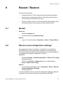
9
Restart / Restore
There are three options:
9.1
•
Restart the phone. Can be used when settings shall be applied.
•
Remove local configuration settings. The settings that are done
from the phone UI and web UI are lost.
•
Restore to factory default. The phone gets the same data as when
leaving the factory and removes any saved directory files.
Restart
Phone UI
•
Press the Options key
•
Scroll down and select Restart Phone
Web UI
•
9.2
Log in to the web interface. Operation > Reset > Restart Phone
Remove local configuration settings
All configuration made on the phone, via Web UI or configured by
MX-ONE at logon is stored as local configuration in the phone. By
removing the local configuration the administrator can ensure that phone
is configured according to configuration files only.
Phone UI
•
Press the Options > Administrators Menu > Erase Local Config
Restart the phone.
6739i; Press Options > Advanced (log in as administrator) >
Reset > Erase Local Config.
Web UI
•
Log in to the web interface. Click on Operation > Reset > Remove
Local Configuration Settings.
Restart the phone.
It is also possible to remove the local configuration settings registered
terminals, by entering the following command from MX-ONE:
26/1531-ANF 901 14 Uen E10 2014-01-22
27
AASTRA 6700I SIP TERMINALS FOR MX-ONE
extension_unregistration with parameter forced
9.3
Restore to Factory Default
Factory default reset will force the phone to go back to the initial setting.
If configuration server is not set via dhcp options, you will need to set it
again. If the configuration server shall be accessed via https, only the
commercial root CAs (Verisign etc) are preloaded.
Phone UI
•
Options > Administrators Menu > Factory Default
6739i; Press Options > Advanced (log in as administrator) >
Reset > Factory Default.
Web UI
•
28
Log in to the web interface. Click on Operation > Reset > Restore
to Factory Defaults
26/1531-ANF 901 14 Uen E10 2014-01-22
ENTERING ADMINISTRATOR MODE
10
Entering Administrator Mode
Phone UI
•
Press
(options) key
•
Scroll down and select Admin Menu
6739i; select Advanced.
•
Enter the administrator password: 22222 (which is the default password but can be changed)
Web UI
•
Find the IP address of the telephone by selecting Options > Phone
Status > IP & MAC Addresses
•
Enter the IP address to the telephone into the address field in the
web browser in the PC and press enter.
•
Log in to the web interface by enter
User name: admin
Password: 22222 (which is the default password)
26/1531-ANF 901 14 Uen E10 2014-01-22
29
AASTRA 6700I SIP TERMINALS FOR MX-ONE
11
Configuring the Phone
This chapter describes how to configure the phone from the phone
menus as an administrator.
This chapter also covers the configuration via the configuration files,
aastra.cfg, <model>.cfg or <mac>.cfg.
The parameters can be set in any of these configuration files, but in this
section it is the recommended placing that is described. If one parameter
occurs in several configuration files, it is always the last read parameter
value that the telephone uses.
11.1
Settings mode
To enter into settings mode in the phone user interface:
•
Press
(Options key)
To enter the web user interface:
11.2
•
Find the IP address of the telephone by selecting Options > Phone
Status > IP & MAC Addresses
•
Enter the IP address to the telephone into the address field in the
web browser in the PC and press enter.
•
To log in to the end user page, see 12.2 Web Interface Passwords
for End Users on page 63
•
To log in to administrator page, see 10 Entering Administrator
Mode on page 29.
Settings in the configuration file aastra.cfg
The necessary settings in the configuration file for getting the telephones
to work in a correct way with MX-ONE are created automatically when
using MTS. In the configuration file aastra.cfg the parameters must
have the following values:
! sip aastra id: 1
! sip send line: 1
! sip xml notify event: 1
! sip pai: 1
! directed call pickup: 1
30
26/1531-ANF 901 14 Uen E10 2014-01-22
CONFIGURING THE PHONE
! directed call pickup prefix: Pickup
! collapsed context user softkey screen:1
softkey selection list: "none,speeddial,line,xml,speeddialxfer,speeddialconf,phonelock,empty" *)
*) the options for the softkeys that are working with MX-ONE and is
presented in the web UI.
11.3
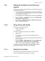
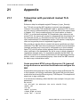
Automatic LAN Access Control, IEEE802.1x
The IEEE802.1x standard is used for port access control
authentication. The LAN switch must support IEEE802.1x signalling
and there must be a RADIUS server handling the authentication. This
feature supports both EAP-MD5 and EAP-TLS protocols.
Figure 3: Components in LAN access control
Below is an example of the settings in the phone configuration file
(aastra.cfg) when EAP-TLS shall be used:
eap type: 2
identity: Phone_Floor1
802.1x root and intermediate certificates:aastra67xxi/Aastra_Client_ca.pem
802.1x local certificate:aastra67xxi/Aastra_Client_cert.pem
802.1x private key: aastra67xxi/Aastra_Client_key.pem
802.1x trusted certificates: aastra67xxi/Aastra_Client_ca.pem
The certificate shall be available on the software server. In the example
above they are stored under the folder aastra67xxi. The certificate files
must be loaded into the phones before IEEE802.1x is activated.
Below is another example showing how to set the parameters in
aastra.cfg when MD5 shall be used:
26/1531-ANF 901 14 Uen E10 2014-01-22
31
AASTRA 6700I SIP TERMINALS FOR MX-ONE
eap type: 1
identity: Phone1
md5 password: Anypass
LAN switch
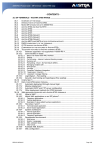
Below is an example how to configure a Cisco switch to enable
IEEE802.1x:
aaa authentication dot1x default group radius
dot1x system-auth-control
radius-server host X.X.X.X auth-port 1812 acct-port 1813
radius-server key XXX
Configuration of an access port for IP telephony:
interface FastEthernetx/0/x
description Aastra accessport
switchport mode access
switchport voice vlan 150
authentication host-mode multi-domain
authentication port-control auto
authentication periodic
authentication timer reauthenticate 120
authentication violation protect
dot1x pae authenticator
auto qos voip trust
mls qos trust dscp
spanning-tree portfast
Radius server
In the Radius server the certificate matching the one in the phones must
be available (when EAP-TLS is used). It is also important to configure
the port to enable the telephony VLAN otherwise the telephone will try to
use the data LAN.
In the example below the settings for enabling of telephony VLAN in the
configuration file for a Radius server from FreeRadius is shown when
using a Cisco LAN switch:
Phone_Floor1 Cleartext-Password := "GJM"
cisco-avpair == "device-traffic-class=voice"
In combination with the examples above (parameters marked with red)
this will mean the telephones with the identity Phone_Floor1 will use
VLAN 150.
For more information about how to set up IEEE802.1x in the phones, see
Administrator Guide for Aastra Models 6700i and 9000i Series IP SIP
Phones.
32
26/1531-ANF 901 14 Uen E10 2014-01-22
CONFIGURING THE PHONE
11.4
LLDP-MED
The telephones have support for Link Layer Discovery Protocol for
Media Endpoint Devices (LLDP-MED), which can for example be used
to get the VLAN identity or the emergency location identification number
(ELIN). In this section it is only the VLAN identity that is described. For
information about ELIN, see Administrator Guide for Aastra Models
6700i and 9000i Series IP SIP Phones.
Note: If LLDP is not used in the network, LLDP can be disabled in the
aastra.cfg file, which means that the telephone will start much
faster.
Previously, Aastra IP Phones had a 5 second timer for listening to
LLDP-MED responses when the phone is booting up. If LLDP-MED
responses are received after this initial listening period, the phone will
not get access to the telephony VLAN. If there is an untagged LAN, the
phone will use it and may be hanging in a DHCP negotiation.
Dependant on when the phone was manufactured, this problem can still
occur at new installation. If this problem occurs, the recommendation is
to set the timer in the LAN switch temporarily to 5 seconds, start the
phones with an aastra.cfg file where the time (parameter lldp startinterval) is changed to match the time in the LAN switch at ordinary operation for example 32 seconds. When the phones are started, the timer
shall be changed back to the original value in the LAN switch.
The example below shows which parameters to set in aastra.cfg:
# LLDP enabled = default
lldp: 1
# LLDP update interval 30 s
lldp interval: 30
# Controls the LLDP start interval, 32 s
lldp startinterval: 32
The parameter lldp startinterval is only valid during the phone bootup
process and it will control the LLDP time-out interval where the phone
sends LLDP advertisements and listens for the LLDP responses from
the switch before proceeding to the DHCP stage. The default value of
this parameter is 32 seconds.
For more detailed information see Administrator Guide for Aastra
Models 6700i and 9000i Series IP SIP Phones.
11.5
Enabling / Disabling DHCP
Follow the steps below to enable or disable DHCP:
26/1531-ANF 901 14 Uen E10 2014-01-22
33
AASTRA 6700I SIP TERMINALS FOR MX-ONE
Options > Admin Menu[6739i; select Advanced] > Network Settings
> DHCP Settings > DHCP
11.6
Setting the Phone's IP Address
If DHCP is used, the phone's IP address is set automatically, using the
DHCP server. To be able to set the phone's IP address manually, DHCP
must first be disabled on the phone, see 11.5 Enabling / Disabling DHCP
on page 33.
Options > Admin Menu [6739i; select Advanced]> Network Settings
> IP Address
11.7
Setting the IP Address to the Default
Gateway
If DHCP is used, the IP address to the default gateway is set automatically, using the DHCP server. To be able to set the IP address to the
default gateway manually, DHCP must first be disabled on the phone,
see11.5 Enabling / Disabling DHCP on page 33.
Options > Admin Menu[6739i; select Advanced] > Network Settings
> Gateway
11.8
Setting the IP Address and Download
Protocol of the Software Server
To download the phone software and configuration files, the phone must
be configured with the type of protocol and IP address matching the software server (configuration server). The configuration server can be set
using these alternatives:
34
•
Manually from the phone UI; Options > Admin Menu > [6739i;
select Advanced]> Configuration Server.
•
Manually via the administrator web UI: Click on Advanced
Settings > Configuration Server
•
Automatically using DHCP, see 18.1 Data from DHCP on page 71.
26/1531-ANF 901 14 Uen E10 2014-01-22
CONFIGURING THE PHONE
11.9
Setting the IP Address of the SIP proxy /
registrar
The phone is configured with the IP address of the SIP proxy using one
of the following methods:
11.10
1.
In the configuration file aastra.cfg in the parameter: sip proxy ip.
The necessary settings in the configuration file for this are created
automatically when using MTS.
2.
In the configuration file <mac>.cfg in the parameter: sip proxy ip.
3.
Phone UI: Options > Admin Menu > [6739i; select Advanced] >
SIP Settings > Proxy IP/Port
4.
Web UI: Click on Advanced Settings > Global SIP > Basic SIP >
Basic SIP Network Settings
Using Virtual LAN (VLAN)
The following VLAN data can be set:
•
Enable VLAN tagging
•
VLAN identity
The following configuration alternatives are available:
•
aastra.cfg file.
•
Link Layer Discovery Protocol for Media Endpoint Devices
(LLDP-MED).
•
In DHCP option 43, see section 18.3 DHCP Settings for Option 43
and 60 on page 72.
•
Phone UI. Options > Admin Menu > [6739i; select Advanced] >
Network Settings > Ethernet & VLAN - VLAN Settings
•
Web UI: Click on Advanced Settings > Network > VLAN
For detailed configuration information, see Administrator Guide for
Aastra Models 6700i and 9000i Series IP SIP Phones
11.11
Setting Time and Date
Time and date are set via the NTP protocol from a time server.
The time and data format is also possible to change.
26/1531-ANF 901 14 Uen E10 2014-01-22
35
AASTRA 6700I SIP TERMINALS FOR MX-ONE
The following configuration alternatives are available:
•
aastra.cfg file.
•
Phone UI. Options > Preferences > Time and Date
•
Web UI: Click on Preferences > Time and Date Settings
It is possible to use LIM 1 in MX-ONE as a NTP server.
11.12
Configuring Language Settings
The language for the display texts and the language for the input via the
key pad can be set.
English is always available in the telephone and cannot be removed. It
is possible to add more languages via the configuration file and to define
the default language. Example:
lang 1: lang_de.txt
lang 2: lang_fr.txt
lang 3: lang_es.txt
lang 4: lang_sv.txt
language: 4
In the example, English, German, French, Spanish and Swedish will be
shown in the phone menu with Screen Language and the default
language will be Swedish.
See also, section 8.1 Phone software and configuration files on the software server on page 24 and section 7.3.1 Log on with Soft key on page
21.
Change the language in a telephone by:
•
Phone UI. Options > Preferences > Language
•
Web UI: Click on Basic Settings > Preferences > Language
Settings
Some text strings are sent out to from the PBX to the telephone. To order
the PBX to send out the right language enter from the telephone:
*08*n# where n is the language number in MX-ONE.
The labels for Message Waiting and for CorpDir must be translated by
the system administrator, by using Manager TS to change the label for
this key, or by editing the model specific configuration file for each phone
model.
36
26/1531-ANF 901 14 Uen E10 2014-01-22
CONFIGURING THE PHONE
11.13
Using Shortcut Keys
Shortcut keys can be of two types:
11.13.1
•
System keys. Keys that are common on all terminals within a
certain model. Example: log on/off, diversion, message waiting,
corporate directory, etc.
•
Individual keys. Keys that are unique for each user. Example:
speed dial, monitoring keys, extra directory number etc.
Key numbering
The numbering of the keys for the different models are shown in the
Administrator Guide for Aastra Models 6700i and 9000i Series IP SIP
Phones.
There are the following types of keys that can be used as shortcut keys:
•
Softkeys. In 6737i/57i, 6735i/55i and in 6739i.
•
Top Softkeys. In 6737i/57i.
•
Programmable keys (hard keys). In 6730i/31i, Aastra6753i,
6735i/55i.
•
Expansion module key, see section 14 Expansion Modules on
page 65.
The softkeys are reserved in the following way:
•
1-4, system keys. For MX-ONE busy services (call back call pickup
etc.) and for xml kit applications. These are predefined as key type
XML in aastra.cfg and will get the actual key label and value when
busy services is offered.
•
5, system key. Logon/Logoff is the first key visible in idle state.
•
6, system key. For Corporate Directory search (if this feature shall
be used).
•
7, system key, For Diversion in 6739i. In the other terminal models
can softkey 7 be used for system key functions which shall be equal
on all telephones in a model, see 11.13.2 Default key layout on
page 39.
•
8, system key to be defined by the system administrator, see
11.13.2 Default key layout on page 39.
•
9 and upwards, individual keys. The following features are available and programmed form the PBX:
–
BLF keys (MNS keys)
26/1531-ANF 901 14 Uen E10 2014-01-22
37
AASTRA 6700I SIP TERMINALS FOR MX-ONE
–
Speed dial (TNS) key. Can also be programmed from a menu
in the telephone or from the web interface in the phone.
–
Personal Number (PEN) key
–
Shared Call Appearance (SCA) key
–
Extra Directory Number (EDN) key
–
Malicious Call Trace (MCT) key
The connection between the soft key number in the phone and the
logical key number when initiating a key in MX-ONE is: The logical
key number 1 corresponds to soft key number 9 in the phone,
logical key 2 to softkey 10, etc.
The first available key number that can be used as an individual key
is defined in the configuration file in MX-ONE:
/etc/opt/eri_sn/ip_telephony.conf
Softkeys of the type none are not shown in the display. For example; if
the softkey with key number 10 is programmed with a speed dial
number, the softkey will show up in the telephone display on the first key
position with type equal to none. If the user want to have the key on the
phone display on the same position as where the key was programmed,
the softkeys must be set to type equal to empty.
The top softkeys are reserved in the following way (only 6737i/57i):
•
1-5, system keys, see 11.13.2 Default key layout on page 39.
•
6-10, individual keys of the type: speeddial, xml, none, empty
speeddialxfer, speeddialconf or phone lock.
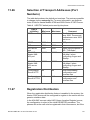
Table 3 Number of Shortcut keys
Hard
keys
Model
38
Soft
keys
Comment
6730i/ 31:
8 top
-
6739i:
-
55
6753i:
6
6735i/
55i:
6 top
6 bottom
20 bottom softkeys on 4
pages.
6737i/
57i:
-
6 top, 6
bottom
20 bottom softkeys on 4
pages.
10 top softkeys on 2 pages.
This model must have an
expansion module if MNS,
TNS (initiated from the PBX)
MCT, PEN shall be used.
26/1531-ANF 901 14 Uen E10 2014-01-22
CONFIGURING THE PHONE
Expansion modules can be added to 6753i, 6735i/55i, 6737i/57i and
6739i.
When adding an expansion module to the telephone, the keys for MNS,
TNS (defined in the PBX), MCT and PEN are moved from the telephone
to the expansion module.
11.13.2
Default key layout
This chapter shows the default key layout per model. The following
system keys can be changed or removed via Manager TS or via editing
the model specific configuration files.
•
Services
•
Local Directory
•
Callers List
•
Message Waiting
•
Corporate Directory
If one of these functions is removed, it can be replaced by a key with
another function that shall be generic for all phones of a certain model.
The following options are possible to set:
•
speeddial
•
xml
•
speeddialxfer (the softkey is configured to transfer calls and
configured for speed dialing to a specific number.)
•
speeddialconf (the softkey is configured as a speed dial key and
as a conference key.)
•
phone lock (the key is used to lock / unlock the phone).
•
none (the softkey is not used)
•
empty (the softkey is configured to force a blank entry on the phone
display
The following keys that are pushed out from MX-ONE Telephony Server
and can not be changed via Manager TS, they need to be edited manually in config file /etc/opt/eri_sn/ip_telephony.conf.. (If the key values
are set to “”, they are not pushed to the phone). This file must be
changed in all servers in the system. At upgrading of the MX-ONE software this file have to be edited again. ‘restart -u SIPLP’ is required after
the file is edited to activate changes.
•
Logon/Logoff
•
Diversion
26/1531-ANF 901 14 Uen E10 2014-01-22
39
AASTRA 6700I SIP TERMINALS FOR MX-ONE
The first individual key index and key base (prgkey,softkey or topsoftkey)
is also set via ip_telephony.conf
The <MAC>.cfg can be used for a phone to override the default key
layout. You may decide that the a specific phone shall have an extension
number which shall not be logged off and not to be used for free seating.
See Chapter “Logon/Off Key Not Used”.
See also 8.2 Installing the Firmware / Configuration files on page 25.
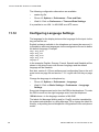
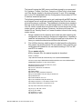
The default key layout for the different models is shown below.
Services
LocalDir
CallList
MsgWaiting
Diversion
More
Logon /Log off
CorpDir
Figure 4: Aastra 6737i/57i
40
26/1531-ANF 901 14 Uen E10 2014-01-22
CONFIGURING THE PHONE
Services
LocalDir
CallList
MsgWaiting
Diversion
Logon /Log off
CorpDir
Figure 5: Aastra 6735i/55i
Save (directory)
Delete (directory)
Local directory
Callers list
Transfer
Log on /off
Figure 6: Aastra 6753i
26/1531-ANF 901 14 Uen E10 2014-01-22
41
AASTRA 6700I SIP TERMINALS FOR MX-ONE
Log on/off
CorpDir
Diversion
MsgWaiting
Callers list
Services
Figure 7: Aastra6739i
Log on / off
Save contacts
MsgWaiting
Delete contacts
Diversion
Directory (*)
Services
Callers list
(*) Local or corporate
Figure 8: Aastra 6730/31
42
26/1531-ANF 901 14 Uen E10 2014-01-22
CONFIGURING THE PHONE
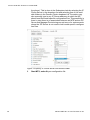
11.13.3
Flexible IP Function keys in MP
For most telephone models, Manager Provisioning makes keys available for individual programming based on the assumption that both
ip_telephony.conf and the model specific configuration file has standard
definitions. For the 6730i and 6731 models, Manager Provisioning
analyzes the actual settings to determine which function keys are available for individual programming.
The function keys defined for an Aastra67xxi terminal depends on two
configuration files:
•
the global ip_telephony.conf
•
model specific, e.g. 6731i.cfg.
The ip_telephony.conf file is stored in the MX-ONE Telephony Server
and is read by it at start-up but not by the telephones directly. This file
contains telephone model specific definitions of function keys that shall
be pushed to the telephone, e.g. Log on/off and Diversion keys. Also a
key offset is defined per model type which defines an offset number of
the first key that can be programmed in the TS.
The model specific configuration file, e.g. 6731i.cfg, is read by the telephones and contains this model’s default definition of the function keys
layout. These files can be defined and changed in the Configuration File
task in MTS, see chapter 6.
Example - Make all function keys programmable
In this use case all keys will be freed up for the user to be programmed
individually.
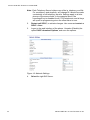
Do as follows:
1.
Edit /etc/opt/eri_sn/ip_telephony.conf in MX-ONE Telephony
Server ,so it looks like the following example :
Figure 9: Configure file
26/1531-ANF 901 14 Uen E10 2014-01-22
43
AASTRA 6700I SIP TERMINALS FOR MX-ONE
Note: Each Telephony Server holds a copy of the ip_telephony.conf file.
For consistency and simplicity, any change to it should be made
consistently on all telephony servers. Settings apply to all telephones of the same model: In the example above, the
logon/logoff key is disabled for all 6731i telephones, and all keys
are open for programming since the offset value is zero.
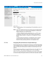
2.
Restart unit SIPLP, to activate changes. Use command restart -u
SIPLP --lim x.
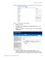
3.
Logon to the web interface of the phone. Unmarke (Disable) the
option DHCP download Options, and save the options.
Figure 10: Network Settings
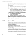
4.
44
Select the right SW Server.
26/1531-ANF 901 14 Uen E10 2014-01-22
CONFIGURING THE PHONE
Figure 11:Configuration Server Settings
5.
Restart the phone.
6.
Open MP, and click Telephony tab. Add a SW server for your
configuration files.
7.
Restart a unit SIPLP, to activate changes, use command restart
-u SIPLP-lim x.
Figure 12: SW Server
8.
Specify a IP Phone server and a domain folder, if used.
In MP the default IP Phone Server and Domain Folder has to be
setup to point to the correct configuration file (the same as used by
26/1531-ANF 901 14 Uen E10 2014-01-22
45
AASTRA 6700I SIP TERMINALS FOR MX-ONE
the phone). This is done in the Subsystem task by selecting the IP
Phone Server in the dropdown list and selecting one of the available folders in the Domain Folder dropdown list.The admin may
also manually type in any IP Server address, at which the MP
should read the model specific configuration files. This possibility is
there in case there is no association between an MTS and an IPP
Server that Manager Provisioning can retrieve or for environments
where the IPP Server is not used to hold model specific configuration files.
Figure 13:Specify IP Phone server and domain folder
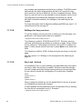
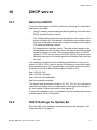
9.
46
Start MTS, and edit your configuration file.
26/1531-ANF 901 14 Uen E10 2014-01-22
CONFIGURING THE PHONE
Figure 14:MTS settings, in this example keys 2-8 are flexible as key 1 is
locked.
Note: If you want a different function keys layout on some special extensions even if they are using the same telephone model as the
default extension, you can do this by:
1. Define a different model configuration file, e.g. 6731i.cfg, in
Configuration File task in MTS, see chapter 6, and store it in
another folder (Domain or Subnet) or on a different IP Phone
Server.
2. Edit the special extensions in the Extension task, click the
“Advanced” button and select the IP Phone Server and/or
Domain Folder previously defined in the dropdown lists.
11.13.4
Assigning Phone Numbers to Speed dial keys
Shortcut keys that are not assigned to functions or monitored extensions
can be assigned to phone numbers as speed dial keys (also called TNS
keys). The user can initiate phone numbers to shortcut keys from the
web UI.
When programming softkeys as speed dial keys from the web UI do not
use key number 1-8 for bottom softkeys and 1-4 for top softkeys.
When a user has programmed a speed dial key the number and the label
are stored locally in the phone and do not follow the user when he/she
26/1531-ANF 901 14 Uen E10 2014-01-22
47
AASTRA 6700I SIP TERMINALS FOR MX-ONE
logs on with another telephone. Speed dial data initiated via MX-ONE
follows the user.
To program speed dial to a programmable key (hard key) that is empty
from the phone UI:
1.
Press the key for a couple of seconds until the input field appears
in the display.
2.
Enter the name and the number (or procedure with * and #).
Note: In 6735i/55i and 6737/57i the recommendation is to not use the
phone UI for the programming of softkeys as speed dial keys
because it will interfere with the keys used by the system. In
6739i it is ok when using the Options key
> Softkeys to
program the softkey with higher key number than 8.
To program a speed dial key (hard keys and soft keys) from the web UI:
1.
Click on: Operation > Softkeys and XML or
Operation > Programmable keys or
Operation > Expansion Module
2.
Enter the name and the number (or procedure with * and #).
Note: Do not program softkey 1-8 because these can interfere with keys
used by the system.
To edit an existing speed dial key from the phone UI:
Options > Preferences > Speed Dial Edit.
11.13.5
Assigning MNS Keys
The shortcut keys can be configured as monitoring keys (that is,
assigned to monitor other extensions). The LED of the shortcut key is
used for indicating the status of the monitored extension. By pressing the
shortcut keys, calls to monitored extensions can be answered. Secretary
functions is one example of this.
Monitoring keys are configured from the PBX.
To get the MNS key working, some parameters in the configuration file
have to be enabled, see section 11.2 Settings in the configuration file
aastra.cfg on page 30.
It is possible to change the type of ring signal (periodic, muted, visual
only etc.) for the MNS key and it is changed from the PBX or from
Manager Provisioning. The default value is visual only. No settings for
this can be done in the aastra.cfg file.
It is also possible to set a pop-up option for monitoring keys. With this
feature enabled, the page containing a monitor key is displayed when a
48
26/1531-ANF 901 14 Uen E10 2014-01-22
CONFIGURING THE PHONE
call to the associated monitored extension is received. This feature is
enabled in the aasta.cfg file:
blf activity page switch:3
There are the following options:
•
0: Page switching disabled. Default value.
•
1: Switch page when the monitored extension receives a call.
•
2: Switch page when the monitored extension receives a call or put
the call on hold.
•
3. Switch page when the monitored extension receives a call or put
the call on hold or when the monitored extension change to speech
state.
To avoid too much flashing of switching pages, all the MNS key should
be collected on one page.
11.13.6
Shared Call Appearance (SCA)
The SCA feature allows a group of terminals to control the incoming and
outgoing calls on a common line. The SCA feature is useful in work
groups where it must be easy to exchange and move calls between the
members.
The following terminal models can be initiated to have SCA lines: Aastra
6730i/31i, 6739i, 6735i/55i, 6737i/57i.
The extension number for a SCA line can be represented on a number
of terminals. The main SCA extension number for a certain terminal is
placed on L1 and L2. If the terminal shall monitor another SCA line, the
hardkeys L3 and L4 are used. If additional monitoring SCA lines are initiated, they are represented on softkeys.
The reason to initiate two lines (e.g. L1 and L2) for each SCA number, is
that if L1 is busy it is still possible to take another call on L2.
For a detailed description of the SCA feature in an MX-ONE environment, see feature description Shared Call Appearance.
For a description of the lamp indications when the SCA feature is used,
see the Quick Reference Guide for each telephone model.
The SCA feature is initiated with Manager Provisioning (or via the
MX-ONE command interface). No settings in the aastra.cfg file are
needed.
11.13.7
Extra Directory Number (EDN)
One or several Extra Directory Numbers can be added to an existing
extension which has an own directory number on Line1. The extra direc-
26/1531-ANF 901 14 Uen E10 2014-01-22
49
AASTRA 6700I SIP TERMINALS FOR MX-ONE
tory numbers are represented on line keys or softkeys. The EDN number
has basically the same characteristics as the Line1 except for busy;
when there is a call on an EDN line, the line is regarded as busy. When
there is a call on Line1 it is still possible to receive another call on Line2.
The EDN keys are initiated with Manager Provisioning (or via the
MX-ONE command interface). No settings in the aastra.cfg file are
needed.
For more information how to initiate the softkeys as EDN keys, see 11.13
Using Shortcut Keys on page 37.
11.13.8
Softkeys for busy services
To get the softkeys for busy services to show up on the first page, one
parameter in the aastra.cfg file has to be enabled:
! collapsed context user softkey screen:1
The following is valid for 6735i/55i and 6737i/57i: The busy services
call-back and call pickup are shown on softkeys on page 1 when calling
a busy extension. Call waiting and intrusion are shown on softkeys on
page 2, which means that the user has to press More to see these soft
keys.
The following is valid for 6739i: All busy services are shown on the first
page.
See also section 11.2 Settings in the configuration file aastra.cfg on
page 30.
11.13.9
Key Lock / Unlock
It is possible to lock or unlock softkeys, programmable keys and expansion keys. When key locking is enabled, the phone uses the settings
from the configuration files and ignores any previous local configuration.
A user cannot override the configuration of a locked key. Example:
#Save
prgkey5 locked: 1
#Delete
prgkey6 locked:1
When viewing the locked key via the Aastra Web UI, the key is grayed
out (disabled) and cannot be changed.
It is also possible to lock parameters in the configuration files, by starting
the line with an exclamation mark (!). Example:
! collapsed context user softkey screen:1
50
26/1531-ANF 901 14 Uen E10 2014-01-22
CONFIGURING THE PHONE
11.13.10
Conference key
The hard key for conference in A6730i/31i/39i is defined in the
aastra.cfg template file, and of course when using MTS to create the
configuration file, to send a DTMF digit to the exchange. The possibility
to initiate a three part conference locally in the phone is disabled.
The conference softkey sends an xml request to the exchange to initiate
a conference.
11.14
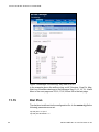
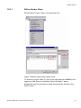
Initiating Data from Manager Provisioning
Manager Provisioning (MP) is used to set data e.g. for MNS, TNS, MCT
and PEN into the phones from MX-ONE. MP can be used by system
administrators and by end-users. The screenshots below shows the
menu in MP for setting data on the softkeys in a 6757i terminal.
26/1531-ANF 901 14 Uen E10 2014-01-22
51
AASTRA 6700I SIP TERMINALS FOR MX-ONE
Figure 15:Manager Provisioning. Key data for 6757i
In the example above the softkeys Log on/off, Services, Corp Dir, Msg
Wait, key 9 and More belongs to the first page. Key 10,11, 12, 13, 14 and
More to the next page and 15,16,17,18,19 and 20 to the last page.
11.15
Dial Plan
The dial plan is defined via the configuration file. In the aastra.cfg file the
following parameters are set:
!sip dial plan: "x+^|xx+*"
!sip dial plan terminator: "1"
52
26/1531-ANF 901 14 Uen E10 2014-01-22
CONFIGURING THE PHONE
With this setting the # character will be sent to the PBX in a correct way,
even in the middle of a procedure for example *42#B-number#.
11.16
Authentication code shall not be visible
When entering a service code procedure containing an authorization and
PIN code, it is possible to prevent the authorization or PIN code to be
stored in the logs. The configuration for this is done in the aastra.cfg file.
There are two options:
•
All the entered digits after the service code are replaced. Example:
the user enters *72*99999# where 99999 is the authorization code,
*72******# will be shown in the display and in the re-dial list.
•
The procedure contains service code + authentication code +
number. In this case the function code and number will be shown in
as they are entered and the authentication code will be replaced by
stars. Example: the user enters *75*99999*6709# where 99999 is
the authorization code and 6709 an extension number,
*75*******6709# will be shown in the display and in the re-dial list.
The syntax to be used in the aastra.cfg file is shown in following
example:
pin suppression dial plan: *72*(X+)# | *75*(X+)*X+#
This setting will give the result shown in the example above.
11.17
Free on Second Line
If the telephone shall be able to receive calls on another line although
there is a call on line 1 already, Call Waiting must be enabled.
Use the web UI:
Global SIP Settings > Basic SIP Authentication Settings.
Call Waiting is also set per line and this setting overrides the global
setting.
The default value is Call Waiting = Enabled.
If the telephone shall send busy when a new call arrives and there is an
ongoing call on the first line, Call Waiting shall be set to Disabled.
26/1531-ANF 901 14 Uen E10 2014-01-22
53
AASTRA 6700I SIP TERMINALS FOR MX-ONE
11.18
Diversion / Call Forward
Pressing the Diversion key gives the the following options:
•
Presence, see 11.21 Configuring Presence Services on page 56.
•
Follow-me. The user must enter the number of the new answering
position.
•
External follow-me. The user must enter the external number
including the external access code.
•
Do Not Disturb. When this option is activated the caller will get an
extension unavailable message or be forwarded to the answering
position, if forwarding is defined by the system administrator. See
also 11.19 Do Not Disturb (DND) on page 55.
•
Divert. The system administrator must define a default personal
number list for the extension in MX-ONE, see feature description
for Personal Number. When divert is activated from the terminal,
the calls to the extension are forwarded to the next position in the
personal number list (normally voice mail).
Note: The Divert function for A6700i SIP extensions is a simplified type
of diversion and has not the same functionality as the diversion
function for digital and analogue telephones.
Note: There is support in Manager Provisioning for setting of the default
personal number list, see 11.18.1 Initiate the Divert Settings
From Manager Provisioning on page 54.
The Diversion key is set from the PBX and cannot be changed.
The phone internal Call Forward menu is disabled by default in the
aastra.cfg file:
call forward disabled: 1
11.18.1
Initiate the Divert Settings From Manager Provisioning
In MX-ONE a default personal number list is used to create the divert
function, see feature description for Personal Number.
In Manager Provisioning (MP) a template can be created for initiating an
extension with the default personal number list. Using this template the
system administrator does not have to fill in the extension number and
voice mail number in the personal number list for each extension when
new extensions are created. Follow the procedure:
•
54
Manager Telephony System (MTS): Initiate a Common Service
Profile (CSP) under the tab Service Category with:
26/1531-ANF 901 14 Uen E10 2014-01-22
CONFIGURING THE PHONE
–
•
11.19
Call List Deactivation Forbidden (which means that the user is
not allowed to deactivate the personal number list)
MP: If a number of new extensions shall be created with default
personal number list:
–
Create a new template for an extension with the CSP created
above.
–
Select Personal Number - > Edit. Use the option ODN (own
directory number) as first position in the list. When the
template is used, the parameter value ODN will be replaced
by the present directory number.
–
In the second position in the personal number list, enter the
answering position (normally the voice mail number).
•
MP: Create the extension by using the template described above.
•
MP: If the default personal number list shall be initiated for an
existing extension:
–
Select the extension. Change the CSP to the one for default
personal number list. Press Apply.
–
Select Personal Number - > Edit. Change the phone numbers
in the list to the wanted numbers.
Do Not Disturb (DND)
It is possible to activate individual DND from the Diversion menu in the
terminals. The extension must have a certain category to be allowed to
activate individual DND. When the feature is activated the forwarding of
calls to the extension is dependant on the settings in MX-ONE. No
settings in the telephone is necessary for this feature. See also MX-ONE
Telephony System Feature List.
It is possible to activate group do not disturb from the telephone with a
service code procedure. The extension must have a certain category to
be allowed to activate group DND. No settings in the telephone is necessary for this feature. See also MX-ONE Telephony System Feature List.
26/1531-ANF 901 14 Uen E10 2014-01-22
55
AASTRA 6700I SIP TERMINALS FOR MX-ONE
11.20
Configuring Ring Signals
The adaptation of the ring signals for the market is made from the configuration file. The tables below shows values to be set for Europe / Standard and for North America application systems.
Table 4 Ring signal cadences for Europe / Standard
Ring
signal
Parameter in
configuration file
External
bellcore cadence dr2
350, 300, 350, 5000
Call back
bellcore cadence dr3
300, 400
Cadence
Table 5 Ring signal cadences for North America
11.21
Ring
signal
Parameter in
configuration file
External
bellcore cadence dr2
800, 400, 800, 4000
Call back
bellcore cadence dr3
400, 200, 400, 200,
800, 4000
Cadence
Configuring Presence Services
These telephones have menu support for activating of absence reasons
(message diversion) under the Diversion key. The menus are pushed
out from the PBX and no settings are required in the configuration file for
the telephone.
When message diversion is active, the lamp at the Diversion key is lit.
Note: It is necessary to set the time and date format in MX-ONE for the
different absence reasons. Use command:
extension_text with parameter ics-time-format
Common answering position(s) must be set as well so the system
has a destination number where to redirect traffic when absence
reason is active. Use command:
CDCOI with parameters
56
26/1531-ANF 901 14 Uen E10 2014-01-22
CONFIGURING THE PHONE
11.22
Using DNS SRV Resource Records
DNS SRV resource records can be used to implement more alternatives
for redundancy than just sip proxy and sip backup proxy. This feature
can also be used when a local branch office sip proxy shall be used.
DNS SRV records can be defined in the DNS server or in the aastra.cfg
file.
The phone performs an SRV lockup when the IP address of the server
is a fully qualified domain name (FQDN) and the corresponding port is
set to 0.
Here is an example when using aastra.cfg:
sip proxy ip: 192.168.0.1
sip proxy port: 5060
sip registrar ip: 0.0.0.0
sip registrar port: 5060
sip backup proxy ip: example.com
sip backup proxy port: 0
sip backup registrar ip: example.com
sip backup registrar port: 0
sip dns srv1 name: _sip_udp.example.com
sip dns srv1 priority: 10
sip dns srv1 weight: 50
sip dns srv1 port: 5060
sip dns srv1 target: mx-one-server2.example.com
sip dns srv2 name: _sip_udp.example.com
sip dns srv2 priority: 10
sip dns srv2 weight: 50
sip dns srv2 port: 5060
sip dns srv2 target: mx-one-server3.example.com
sip dns srv3 name: _sip_udp.example.com
sip dns srv3 priority: 20
sip dns srv3 weight: 60
sip dns srv3 port: 5060
sip dns srv3 target: branch-office-server.example.com
hostfile.txt
192.168.0.2 mx-one-server2.example.com
192.168.0.3 mx-one-server3.example.com
192.168.8.1 branch-office-server.example.com
In the example MX-ONE has ordered the phone to register in MX-ONE
server 1 as primary registrar. If server 1 is not available, the phone will
use the DNS SRV record with lowest priority, that is record #1 or #2 both
with 50 percentage probability, which means that the phone will register
towards server 2 or server 3.
MX-ONE must know the IP domain name, that is example.com above.
If all MX-ONE servers are unavailable, the phone will use record #3 and
register towards the branch office registrar.
26/1531-ANF 901 14 Uen E10 2014-01-22
57
AASTRA 6700I SIP TERMINALS FOR MX-ONE
The hostfile.txt is used to translate the domain name to IP address. This
file shall be available on the sw server together with the aastra.cfg file.
The host file is downloaded to the phone at restart.
When the telephone is registered towards the backup registrar and when
the user initiates a call, the INVITE will be sent to the primary registrar
first, which causes a delay of the call with 3-4 seconds. The telephone
will discover when the primary registrar is working again and register
towards this one.
There are some limitations when the telephone is registered towards the
backup registrar, see 11.28.1 Limitations on page 60.
11.23
Using the Phone as an Operator Media
Device (OMD)
Not applicable.
A telephone is called Operator Media Device when it is used for the
speech together with a operator work station application, for example
CMG NOW Attendant.
11.24
Central Storage of User Specific Data
The data the that follows the user for the Aastra 6700i family when
logging on to another phone is the data stored in MX-ONE, for example
MNS, SCA keys and the speed dial keys initiated from MX-ONE. The
data locally stored in the phone does not follow the user.
11.25
Configuring the Diffserv Parameter
Diffserv is a model for handling of priority, based on the type of service
(TOS) field in the IP packet heading.
The TOS value can be defined in the aastra.cfg file and the parameter
names are: tos sip and tos rtp.
The default values are tos sip: 38 AF/(100110) and tos rtp: 46
EF/(101110)
For more information: see Administrator Guide for Aastra Models 6700i
and 9000i Series IP SIP Phones.
58
26/1531-ANF 901 14 Uen E10 2014-01-22
CONFIGURING THE PHONE
11.26
Selection of Transport Addresses (Port
Numbers)
The table below shows the default port numbers. The ports are possible
to change via the aastra.cfg file. For more information, see Administrator Guide for Aastra Models 6700i and 9000i Series IP SIP Phones.
Table 6 UDP/TCP default ports used by the phone
Type of
signalling
11.27
Minimum
Maximum
Comment
RTP
3000
The first media stream,
uses 3000. The second
mediastream uses 3002
and so on.
RTCP
3000+1
RTP port + 1
SIP
5060
5060
SIP secure
port
5061
5061
When using the phone in
SIP / TLS mode.
MX-ONE
Aastra XML
API port
22222
22222
Used in combination
with http:// when
configuring /Logon and
/Startup
MX-ONE
Aastra XML
API secure
port
22223
22223
Used in combination
with https:// when
configuring /Logon and
/Startup
Configuration
Server HTTP
80
80
when downloading
configuration and
firmware files
Configuration
Server HTTPS
443
443
when downloading
configuration and
firmware files
Registration Distribution
When the registration distribution feature is enabled in the system, the
Aastra 6700i phones will be configured to register in the server with the
generic extension data.
In the MX-ONE concept called HLR (Home Location Register) server,
the configuration is a part of the initial REGISTER procedure. The
phones will as the main rule be registered in their home server, but if the
26/1531-ANF 901 14 Uen E10 2014-01-22
59
AASTRA 6700I SIP TERMINALS FOR MX-ONE
HLR server has reached its limit, an alternative server will be able to
accept the registration.
When this feature is used, the balancing of the registration load has to
be considered already during the deployment of the system, e.g. an
even initiation of the generic extensions among the available servers.
To activate the registration distribution feature in MX-ONE enter the
command:
extension_registration_distribution -i
11.28
Redundancy
The primary proxy IP address shall be set according to 7.3.1 Log on with
Soft key on page 21. It is also possible to define in the aastra.cfg file a
redundant IP address with the parameters:
sip backup proxy ip
sip backup registrar ip
The IP address to set shall be equal in both of these parameters. The
redundant ip address will be used by the telephone if the sip proxy server
with the primary ip address does not respond.
When the telephone is registered towards the backup sip registrar, the
telephone tries to register towards the primary server. If this server
responds, the phone tries to register towards the primary proxy server
again.
There is support for redundancy settings in Manager TS.
For more information about the redundancy functionality in MX-ONE,
see feature description for HLR Redundancy.
11.28.1
Limitations
When the phone loses contact with the primary SIP registrar, it can take
up to 10 minutes (refresh of the registration time) before the telephone
registers towards the backup registrar.
Aastra 6700i terminals, deployed with Log On/Off xml key, cannot use
the key when the primary proxy/registrar is not responding. As a workaround it is possible to log on with the free seating procedure
(*11*PIN*extension number#).
If the terminal is registered towards the backup registrar and if the user
logs off with the #11# procedure, the IP address to the primary SIP proxy
is lost and it is only possible to log on towards the backup SIP proxy. To
go back to primary SIP proxy, the local configuration settings have to be
removed in the phone, see 9.2 Remove local configuration settings on
page 27.
60
26/1531-ANF 901 14 Uen E10 2014-01-22
CONFIGURING THE PHONE
When the telephone is registered towards the backup registrar and when
the user initiates a call, the INVITE will be sent to the primary proxy first
and then to the backup proxy, which causes a delay of the call with 3-4
seconds.
11.29
Registration at Branch Offices
The branch office scenario means that the telephones are registered to
to PBX in the main office and if the connection to the main office fails, the
phones shall register to a local SIP server.
When the connection to the main office is working again, the telephones
shall register towards this PBX again.
The way to configure this is to use sip backup proxy ip and sip backup
registrar ip in the aastra.cfg file, see section 11.28 Redundancy on page
60 or see 11.22 Using DNS SRV Resource Records on page 57.
11.30
Voice Mail
When a user has got a voice mail and the message waiting key is
flashing, the user can listen to his voice mail by pressing this key. The
telephone will send the *32# procedure to the system.
If there is no message waiting, it can still be useful to call the voice mail
system. This is done by pressing the Services key and select VoiceMail.
In this case the phone will use the directory number to access the voice
mail system.
The settings for these options are defined in the aastra.cfg file. Below is
an example:
sip vmail:”*32#”
sip line1 vmail:”*32#”
sip explicit mwi subscription: 1
servicesscript: http://$$PROXYURL$$:22222/services?user=$$SIPUSERNAME$$
voicemailnr=12345
11.31
Corporate Directory
From the phone it is possible to search in a corporate directory via the
XML interface described in XML API for Aastra SIP phones.
From CMG7.5-SP1 the XML support for searching in the corporate
directory is included.
26/1531-ANF 901 14 Uen E10 2014-01-22
61
AASTRA 6700I SIP TERMINALS FOR MX-ONE
To be able to access the directory function some parameters in the
aastra.cfg file of the phone have to be set, see the example below:
softkey6 label: "Corp Dir"
softkey6 type: xml
softkey6 value: http://<CMG server>/xml/directory/CorpDir.php
softkey6 line: global
softkey6 states: idle, connected, incoming, outgoing
The phone sends a http request with the search criteria to the directory
server and receives a list with the search result. The answer is in xml
format.
The user can select the phone number in the search result and initiate a
call.
11.31.1
CMG directory
For details how to set up CMG to access the corporate directory from the
6700i phones, see Corporate Directory for IP phone, Installation &
Configuration Guide in the CMG CPI library.
11.32
Call Park Pool
For a detailed description of the Call Park Pool feature in an MX-ONE
environment, see operational directions for Call Park Pool.
No configuration in the phone is needed for this feature.
11.33
Intercom
It is possible to define Intercom functionality on one or several programmable keys. When pressing the Intercom key, the telephone initiates a
call towards the other predefined party and the call is automatically
answered.
For a detailed description of the Intercom feature in an MX-ONE environment, see operational directions for Intercom.
No configuration in the phone is needed for this feature.
62
26/1531-ANF 901 14 Uen E10 2014-01-22
PASSWORDS AND PIN CODES
12
Passwords and PIN Codes
The following passwords or PIN codes are used when working with
these phones:
•
PIN code for registering the phones to MX-ONE. The user can
change the PIN code with the procedure: *74*old PIN*new PIN#
It is recommended to use PIN code to avoid that an end-user can
log on with another end-user’s directory number.
12.1
•
Administrator password for accessing the phone using the phones'
web interface or the phone menus.
•
User password for accessing the phone using the phone's web
interface or phone menus.
Changing the Administrator Password
The administrator password can be changed from the aastra.cfg file, see
Administrator Guide for Aastra Models 6700i and 9000i Series IP SIP
Phones. The password can only consist of digits
The user name is: admin
The default password is 22222.
12.2
Web Interface Passwords for End Users
End users can use a Web browser to access the phone's Web interface.
This interface can be used when working with contacts and other user
specific data.
The user name is: user
There is no password by default.
The user password can be initiated/changed via the phone UI:
Options > Option List > User Password
The user password can also be changed via the web UI.
Click on: Operations > User Password
26/1531-ANF 901 14 Uen E10 2014-01-22
63
AASTRA 6700I SIP TERMINALS FOR MX-ONE
13
Headset
Wireless headsets according to the DHSG protocol as well as headsets
with cable can be used with 6735i/37i, 6737/57i, 6739i and 6753i.
To connect the phone to a DHSG compatible cordless headset, a special
cable from Aastra must be used. The article number is: 62-001134-00.
To enable the headset port via the phone UI:
Options > Preferences > Set Audio > Audio Mode
64
26/1531-ANF 901 14 Uen E10 2014-01-22
EXPANSION MODULES
14
Expansion Modules
There are two types of expansion modules; M670i and M675i.
M670i is a key panel unit with 36 keys. Paper labels are used to label the
keys. Maximum 3 modules can be connected to the telephone. The
following models has support for the key panel unit: 6753i, 6735i/55i,
6737i/57i and 6739i.
M675i is a display panel unit with 60 soft keys, with 20 softkeys on each
page which means 3 pages. A LCD display is used to label the keys.
Maximum 3 modules can be connected to the telephone. The following
models has support for the key panel unit: 6735i/55i, 6737i/57i and
6739i.
For installation of the modules, see the phone specific Installation Guide.
When adding an expansion module on the telephone, the keys for MNS,
TNS (defined in the PBX), MCT and PEN are moved from the telephone
to the expansion module.
If shortcut keys shall exist on both the phone and on the expansion
module, the key numbers that do not fit on the expansion module will
‘overflow’ to the telephone display. Key number 1 to 60 are placed on the
expansion module and key 61 and upwards on the telephone, in the
case when one module is used.
26/1531-ANF 901 14 Uen E10 2014-01-22
65
AASTRA 6700I SIP TERMINALS FOR MX-ONE
15
Emergency Calls
Even if the telephone is not registered to the PBX, it is possible to make
emergency calls. The sip proxy ip parameter in the configuration file,
defines where the telephone sends the INVITE with the SOS number.
No registrar is required for this.
For more information how to set up the sent A-number, see Emergency
Calls, SOS calls (5/15431-ANF90143) in the CPI library.
66
26/1531-ANF 901 14 Uen E10 2014-01-22
VOIP RECORDING
16
VoIP Recording
It is possible to record voice calls to a central recording equipment. The
phones that shall have recording are monitored via the CSTA interface
and this means that an Application Link or an Open Application Server
(OAS) must be used to provide the CTI interface to the recording system.
The call events and the IP address to the phones to be monitored are
sent over the CSTA interface.
For more information about the recording solution for MX-ONE Telephony Server see Description for Voice Recording and the Interface
Description for VoIP Recording Interface.
The signalling between the recording system and the IP phones is based
on SIP. The recording system sends an INVITE message to the phone
to inform about the IP address to where the voice packets shall be sent.
A SIP ACK message orders the phone to start forwarding the received
and transmitted RTP streams to the logger.
There are the following options
1.
Total recording: the recording system orders the telephone to
start the recording dependent on the recording policy. All calls or
only external calls to the monitored extensions are recorded for
example.
2.
Record on demand: the user can start and stop the recording by
pressing the recording key.
Note: It is only possible to record IP phones. No other types of phones
shall be monitored.
The voice stream is sent un-encrypted to the recording equipment, if the
original call is without encryption. If the call is encrypted, the telephone
forwards an encrypted voice stream to the recorder. In this case the
encryption keys are sent via the CSTA interface to the recording equipment.
The icon for recording in the display, is shown when the telephone
forwards the RTP stream to the recording system. Moreover it is
possible to configure the phone to play a periodic beep tone.
16.1
Configuration at Total Recording
The recommendation is to use dynamic recording sessions (i.e. per
call), although it is also possible to use static (i.e. per the duration that
the phone is registered). The type of recording session is configured in
the recording system.
26/1531-ANF 901 14 Uen E10 2014-01-22
67
AASTRA 6700I SIP TERMINALS FOR MX-ONE
Below is an example how to set the parameters in the configuration file:
recorder address1: 192.168.1.20
recorder address2: 192.168.1.21
#recording destination1:
recording destination beep: 0
sip services transport protocol: 1
sip services port: 7300
Recorder addressN specifies the trusted IP addresses corresponding to
the recording system.
Recording destinationN specifies the trusted IP addresses corresponding to the destination where the RTP/SRTP streams should be
sent. If these parameters are left undefined, no authentication checks
are performed. This is the case in this example.
Recording destination beep defines if a beep shall be heard to notify that
recording is ongoing.
Sip services transport protocol. The following options exist:
16.2
•
-1: (default), which means that the same protocol will be used as
defined in the parameter sip transport protocol parameter.
•
0: TCP/UDP
•
1: UDP
•
2: TCP
Configuration at Recording on Demand
The prerequisite is that the settings for active recording is done, see
section 16.1 Configuration at Total Recording on page 67.
When the user has pressed the recording key an icon is shown in the
display when the phone has got a confirmation from the recording
system that the recording has started.
The shortcut key for recording is initiated from the PBX.
The URL to the recording system that the telephone sends when the
user presses the recording key, can be defined in one of the following
ways:
68
•
MX-ONE command extension_key. The advantage is that in a
free seating environment, the recording key with the associated url
will follow the user.
•
In the configuration file for the phone. Can be used where it is not
necessary that the key follows the user.
26/1531-ANF 901 14 Uen E10 2014-01-22
VOIP RECORDING
In the second option, the recording key is defined as a key of the type
xml with the url as parameter value. For example with the recording
system from the vendor ASC:
•
Start recording:
http://192.105.88.152:8080/XVOIPService?page=START&
OPN=$SIPUSERNAME$$
where n is the extension number added by the telephone. The IP
address and port number must match the recorder’s listening IP
address and port number.
•
Stop recording:
http://192.105.88.152:8080/XVOIPService?page=STOP&
OPN=$SIPUSERNAME$$
If the URL contains any characters considered as special by Aastra
6700i, they must be escape encoded, see table below.
Table 7 Escape encoding
Character
Symbol
Escape Sequence
Ampersand
&
&
Quote
“
"
Apostrophe
‘
'
Left angle bracket
<
<
Right angle bracket
>
>
26/1531-ANF 901 14 Uen E10 2014-01-22
69
AASTRA 6700I SIP TERMINALS FOR MX-ONE
17
Quality of Service (QoS)
It is not possible to view the QoS statistics via MX-ONE.
70
26/1531-ANF 901 14 Uen E10 2014-01-22
DHCP SERVER
18
DHCP server
18.1
Data from DHCP
The phone has support for DHCP by which the following IP configuration
data can be provided:
•
Own IP address, subnet mask and default gateway, received in the
DHCP standard fields (1 and 3).
•
The VLAN used for the phone can generally be set in option 132 or
be part of Option 43. If the phone’s configuration has another value
than that of the option value it will configure according to the Option
132 value and making a reboot.
•
IP address to the software server. The path to the firmware to be
downloaded from the software server can also be provided as well
as the protocol to be used. The recommendation is to use DHCP
option 66 (TFTP server name), but DHCP option 60 (vendor class
identifier) and option 43 (vendor specific information field) can also
be used.
The following examples show the different possibilities on how to use
option 66,160 or 159 in order to get the IP address or host and its path
to the software server. For http and https it is possible to define the port.
Default port for http is 80 and default port for https is 443:
http://192.168.1.45
http://192.168.1.45/path
http://192.168.1.45:8080/path
http://srv.example.com/path
The default dhcp precedence order is 43, 160, 159, 66. So if the phone
receives the software server configuration in both option 66 and option
43, then option 43 takes precedence over option 66.
If option 66 is already in use, it is possible to set the configuration server
in either option 160 or 159 instead.
18.2
DHCP Settings for Option 66
Enter the URL to the software server according to the example in 18.1
Data from DHCP on page 71.
26/1531-ANF 901 14 Uen E10 2014-01-22
71
AASTRA 6700I SIP TERMINALS FOR MX-ONE
18.3
DHCP Settings for Option 43 and 60
DHCP option 60 (vendor class identifier) and option 43 (vendor specific
information field) can also be used to get the software server address
and also to load a unique configuration file dependant on telephone type.
The first step is to initiate option 60 for each telephone type:
Table 8 Identifier values to be defined in option 60
Model
Identifier Value
6730i
AastraIPPhone6730i
6731i
AastraIPPhone6731i
6735i
AastraIPPhone6735i
6737i
AastraIPPhone6737i
6739i
AastraIPPhone6739i
6753i
AastraIPPhone53i
6755i
AastraIPPhone55i
6757i
AastraIPPhone57i
After option 60 has been entered into the DHCP server, the data in
option 43 has to be entered. The following options exist:
Table 9 Options that can be set in option 43.
Code
Description
02
Configuration server (protocol, server and path).
Syntax: string
03
RCS. Not used in a MX-ONE environment
08
Header to activate the VLAN transfer to the phone.
Syntax: 16 bytes character string
“Aastra(space)Telecom(space)(space)” i. e.
4161737472612054656c65636f6d2020
09
VLAN identity (1-4094)
Syntax: 4 bytes whereas the first and second byte must be
0x00 and third and fourth byte the VLAN id. Example: 100 in
decimal is 00 00 00 64 in hex.
For an example how to configure option 60 and 43 in a Linux environment, see the Administrator Guide for Aastra IP SIP Phones
Below is an example showing how to configure DHCP in a Windows
environment.
72
26/1531-ANF 901 14 Uen E10 2014-01-22
DHCP SERVER
18.3.1
Define Vendor Class
Select Define Vendor Class in the drop down list.
Figure 16:Define and add the vendor class
To enter the Vendor Class ID, click on the right side below ASCII in the
large form field. Enter the Identifier Value from table 7 above.
Repeat this step for each phone model that should be served by this
DHCP server.
26/1531-ANF 901 14 Uen E10 2014-01-22
73
AASTRA 6700I SIP TERMINALS FOR MX-ONE
18.3.2
Set Predefined Options
Select Set Predefined Options to get the menu to enter the option 43
data.
Figure 17:Set Predefined Options
Select appropriate option class from the drop down list and press the
Add button.
74
26/1531-ANF 901 14 Uen E10 2014-01-22
DHCP SERVER
Figure 18:Predefined Options and Values
The data in the Option Type menu has to be entered manually:
Name: Configuration Server URL
Data type: String
Code: 02
Repeat this for each phone model that should be served by this DHCP
server.
If VLAN identity shall be provided via option 43, repeat this for code 08
and code 09, see table 9 Options that can be set in option 43. on page 72
26/1531-ANF 901 14 Uen E10 2014-01-22
75
AASTRA 6700I SIP TERMINALS FOR MX-ONE
18.3.3
Set Scope Options
The last step is to set the URL string.
Figure 19:Set Scope Options
Select appropriate Vendor class and set the User class to Default User
Class. Activate option 002 and enter the URL of the software server
(configuration server) in the input field String value.
Repeat this for each phone model that should be served by this DHCP
server.
If VLAN identity shall be provided via option 43, repeat this for code 08
and code 09, see table 9 Options that can be set in option 43. on page 72
76
26/1531-ANF 901 14 Uen E10 2014-01-22
SECURITY
19
Security
This section describes the encrypted configuration files, SIP signaling
with TLS and media with SRTP.
19.1
Encrypted Configuration Files
The aasta.cfg, <model>.cfg and <MAC>.cfg files can be encrypted
and downloaded to the phone from the software server with the http or
https protocol. Aastra provides a tool for Windows and Linux to encrypt
the configuration files. This tool is called anacrypt. Use the following
procedure:
1.
Create the file security.tuz with the encrypted site key:
anacrypt -i -p <shared_password>
2.
Encrypt the aastra.cfg file:
anacrypt aastra.cfg -p <shared_password>
3.
Encrypt the <model>.cfg file:
anacrypt <model>.cfg -p <shared_password>
4.
If MAC configuration files are used, encrypt the <MAC>.cfg file:
anacrypt <mac>.cfg -m -p <shared_password>
To encrypt all MAC configuration files in a directory:
anacrypt <mac>.cfg -d <dir> -m -p <shared_password>
5.
Store security.tuz, aastra.tuz and <mac>.tuz on the software
server. Reboot the telephones.
The shared password can be 4-32 alphanumeric characters.
The anacrypt tool can be downloaded from www.aastra.com.
19.2
TLS
IP Phones support a transport protocol called Transport Layer Security
(TLS) . TLS is a protocol that ensures communication privacy between
the SIP phones and the Internet. TLS ensures that no third party may
eavesdrop or tamper with any message. persistent TLS is the only mode
supported by MX-ONE. If Ingate is the access for the phone both persistent mutual TLS and persistent TLS are supported. persistent TLS
26/1531-ANF 901 14 Uen E10 2014-01-22
77
AASTRA 6700I SIP TERMINALS FOR MX-ONE
means that the phone will setup a TLS session which it will keep as long
as it is registered (logged on). Both the server and the phone will make
use of the session to setup calls. Persistent mutual TLS is referering to
the additional mutuality in the TLS handshake where the server requests
the the client’s signed certificate. Otherwise only the client requests the
servers certificate.
19.3
SRTP
The IP Phones include support for Secure Real-time Transfer Protocol
(SRTP), using Session Description Protocol Security (SDES) key negotiation, for encryption and authentication of RTP/RTCP messages sent
and received by the Aastra IP phones on your network.
The administrator can choose among the following options:
•
SRTP Disabled (default): IP phone generates and receives non
secured RTP calls. If the IP phone gets a call from a SRTP enabled
phone, it ignores SRTP and tries to answer the call using RTP. If
the receiving phone has SRTP only enabled, the call fails; however,
if it has SRTP preferred enabled, it will accept RTP calls.
•
SRTP Preferred: IP phone generates RTP secured calls, and
accepts both secured and non-secured RTP calls. If the receiving
phone is not SRTP enabled, it sends non-secured RTP calls
instead.
•
SRTP Only: IP phone generates and accepts SRTP secured calls
only; all other calls are rejected (fail)
SRTP Only: IP phone generates and accepts SRTP secured calls
only; all other calls are rejected (fail).
19.4
How to enable security on 6700i terminals
and MX-ONE
A number measures have to be done in MX-ONE and in the configuration file in the phone.
There is support in MTS for enabling security in MX-ONE and in the
6700i phones.
The steps to enable security are:
1.
78
MX-ONE: For setup of security and security policy, see operational
directions VoIP Security (82/15431-ANF90114) in the CPI library.
26/1531-ANF 901 14 Uen E10 2014-01-22
SECURITY
2.
MX-ONE: For certificate handling see operational directions Certificate Management (132/15431-ANF90114) in the CPI library.
3.
6700i phones: The only certificate that is necessary is the root
certificate. The key storage for MX-ONE certificates is
/etc/opt/eri_sn/certs/. The root CA is called, CA.pem. Copy
CA.pem to the configuration server, i.e. the same directory as
where aastra.cfg resides. You may set the file name of the root
certificate via MTS or directly in the aastra.cfg.
4.
Phone aastra.cfg file: below is an example of the parameters:
sips persistent tls: 1
sip outbound support: 1
sip transport protocol: 4 # 0=UDP&TCP,1=UDP,2=TCP,4=TLS
sips trusted certificates: CA.pem
sip outbound proxy ip: 192.168.110.20
sip outbound proxy port: 5061
sip backup outbound proxy:192.168.5.3
sip backup outbound proxy port:5061
sip srtp mode: 1 #0-RTP,1-SRTP preffered,2-SRTP only
With the backup outbound parameters security is enabled towards
the backup server.
If the XML keys provisioned by MX-ONE shall use https, the
following setting is required. port 22223 will trigger MX-ONE to
provision XML keys for Logon/Logoff and Diversion as “https” and
port 22223, which is the TLS port for Aastra-XML.
action uri startup:
”https://192.168.110.20:22223/Startup?user=$$SIPUSERNAME$$”
services script:
https://192.168.110.20:22223/Services?user=$$SIPUSERNAME$$&voicemailnr=<voice mail number>
#download protocol HTTP,HTTPS,FTP,TFTP
download protocol:HTTPS
https server:<IP address of Configuration Server (Tomcat or
webserver of choice)>
https port:443 #443 is the standardport for https
https path:aastra67xxi //path on Tomcat
https client method:"TLS 1.0"
https user certificates:CA.pem #root CA
Phone <model>.cfg:
Either the Logon keys are removed. Then you rely on that the users
logon when prompted due to reboot (triggered by action uri startup
in aastra.cfg), or the /Logon key value needs to be set to
“https://192.168.110.20:22223/Logon?user=$$SIPUSERNAME$$”.
26/1531-ANF 901 14 Uen E10 2014-01-22
79
AASTRA 6700I SIP TERMINALS FOR MX-ONE
Check the CMG documentation if Corporate directory is to use
https (TLS), for example:
https://192.20.22.11/xml/directory/CorpDir.php
5.
Per default a time server (using NTP as protocol) needs to be
enabled via DHCP Option 42 or via configuration parameters. The
configuration parameter has precedence over Option 42. The
phone must have a valid date and time in order to verify the server
certificate’s expiry time. As TLS is a per-hop protocol. It is the
server certificate of ‘outbound proxy ip’ which is verified. In this
example this would be an MX-ONE server.
Configuration parameters
time server disabled:0 #0-enabled,1-disabled
time server1:<ip address or host>
#ref: http://www.pool.ntp.org/en/use.html
6.
If no NTP servers are accessible for some reason it is possible to
disable the check for expire date via WebGUI(Network) or configuration parameter. This will also have the effect that there is no date
and time indication on the phone.
https validate expires: 0 #0-disabled, 1-enabled
19.5
How to enable security for home worker on
Aastra 6700i
If Ingate is used as Session Border Controller (SBC), follow the Installation Guide How to Install an Ingate Solution for Aastra Teleworker Solutions in Stand-alone mode or DMZ/LAN mode behind existing Firewall in
the CPI library.
The principle used here is to configure the SBC to have secure communication on the outside towards the home worker Aastra 6700i terminal
and unsecure communication on the inside towards MX-ONE.
The TLS setup described here will be persistent TLS. If your deployment
requires an even more secure setup, ‘persistent mutual TLS’, then also
read the Appendix, “Teleworker with persistent mutual TLS”.
Furthermore the assumption is that the user would like to be able to use
the terminal in the office and to bring the terminal home (home worker).
For this reason two configuration server directories are set up, inOffice
accessible via http and atHome accessible via https.
The only setting required by the end user is to change the Configuration
Server via phoneUI: Options > Admin Menu > [6739i; Advanced] >
Cfg. Svr., choose HTTP or HTTPS in the Download Protocol list. Activate setting by requesting Options > Restart.
80
26/1531-ANF 901 14 Uen E10 2014-01-22
SECURITY
The benefit having the SBC server certificate signed by a commercial
CA (Verisign, Thawte, GeoTrust, Comodo or CyberTrust) is that these
root CAs are pre loaded in the phone firmware. A root CA is required
prior to the TLS handshake with the Configuration Server when HTTPS
is used as download protocol.
The following example shows how to get it working with an SBC that has
a self-signed server certificate (meaning that the root CA is the server
who has the server certificate). The drawback is that the phone needs to
boot up in the office before it can be brought home in order to load the
root CA, which is used when the phone boots up and access the configuration server via https at home. However, the phone will loose the
loaded CA on “Factory Reset” or if a new firmware is found in the configuration server.
1.
Setup a webserver like Apache and create the path matching the
configuration server setting in the phone configuration. If Apache is
used the /var/www/html/ is the root for the path set in the phone. So
here you create the directories inOffice/ and atHome/.
2.
The InOffice directory shall consist of model specific configuration
files, aastra.cfg and the phone FW (see above). Note, that the root
certificates are loaded but not used as the setting is TCP for SIP
and RTP for media.
Phone aastra.cfg file:
#Only changes from the aastra template is described
action uri startup:
”http://$$PROXYURL$$:22222/Startup?user=$$SIPUSERNAME$$”
services script: https://$$PROXYURL$$:22222/Services?user=$$SIPUSERNAME$$&voicemailnr=<voice mail number>
#download protocol HTTP,HTTPS,FTP,TFTP
download protocol:HTTP
http server:<webserver IP address>
http port:80
http path:inOffice
https server:<SBC outside IP address>
https port:444 #SBC TLS port relay to webserver
https path:atHome
https client method:"TLS 1.0"
https user certificates:CA.pem #root CA
sip transport protocol: 1 #1-UDP,2=TCP,4=TLS
sips trusted certificates: CA.pem #root CA
sip srtp mode: 0 #0-RTP,2-SRTP only
sip proxy ip: 192.168.110.20
sip proxy port: 5060
sip registrar ip: 0.0.0.0
sip registrar port: 5060
26/1531-ANF 901 14 Uen E10 2014-01-22
81
AASTRA 6700I SIP TERMINALS FOR MX-ONE
time server disabled:0 #0-NTP enabled
time server1:<NTP server> #skip this setting if DHCP Options 42 is used
3.
The atHome directory shall consist of model specific configuration
files, aastra.cfg and if you have a selfsigned certificate you should
skip the phone FW as an upgrade will remove the certificate
loaded.
Only changes from the aastra template is described. Set “https” and
the secure port “22223” to invoke XML Requests over TLS
Assuming SBC outside IP address to be: 193.10.10.10
Phone <model>.cfg:
Either the Logon keys are removed. Then you rely on that the users
logon when prompted due to reboot (triggered by action uri startup
in aastra.cfg), or the /Logon key value needs to be set to
“https://193.10.10.10:22223/Logon?user=$$SIPUSERNAME$$”.
If Corporate directory is to be used a TLS port relay can be configured in Ingate the same way as port 444 is setup towards the
configuration server), Let’s say port 445 is set up then the Corporate Directory key value would be:
“https://193.10.10.10:445/xml/directory/CorpDir.php”
Phone aastra.cfg file:
action uri startup: ”https://193.10.10.10:22223/Startup?user=$$SIPUSERNAME$$”
services script: https://193.10.10.10:22223/Services?user=$$SIPUSERNAME$$&voicemailnr=<voice mail number>
#download protocol HTTP,HTTPS,FTP,TFTP
download protocol:HTTPS
http server:<webserver IP address>
http port:80
http path:inOffice
https server:<SBC outside IP address>
https port:444 #SBC TLS port relay to webserver
https path:atHome
https client method:"TLS 1.0"
https user certificates:CA.pem #root CA
sips persistent tls:1
sip outbound support: 1
sip transport protocol: 4 #1-UDP,2=TCP,4=TLS
sips trusted certificates: CA.pem #root CA
sip outbound proxy:193.10.10.10
sip outbound proxy port:5061
sip srtp mode: 2 #0-RTP,2-SRTP only
The proxy and registrar is set via /Startup or /Logon, which will be
the MX-ONE server receiving the XML Request according to the
82
26/1531-ANF 901 14 Uen E10 2014-01-22
SECURITY
Ingate Relay setting for port 22223. However, if
extension_registration_distribution is active the proxy, registrar will
be set according to the extension’s Home Location Register (HLR)
(see the lim setting in command extension -p)
sip proxy ip: 0.0.0.0
sip proxy port: 0
sip registrar ip: 0.0.0.0
sip registrar port: 0
time server disabled:0 #0-NTP enabled
#skip the server setting below if DHCP Options 42 is used
time server1:<NTP server>
Make sure the NTP server is accessible from the home network.
You may use a server from http://www.pool.ntp.org/en/, as for
example 0.se.pool.ntp.org
26/1531-ANF 901 14 Uen E10 2014-01-22
83
AASTRA 6700I SIP TERMINALS FOR MX-ONE
20
Troubleshooting
20.1
Capture logfiles via SYSLOG
When log files for troubleshooting purpose shall be retrieved from the
telephone, it is possible to use the external syslog feature in Linux for
storing or the Kiwi Syslog Server.
Setup the SYSLOGD server
In the MX-ONE system: Uncomment the following line in
/etc/syslog-ng/syslog-ng.conf.in
#
# uncomment to process log messages from network:
#
udp(ip("0.0.0.0") port(514));
Run 'SuSEconfig' to initiate the changes to the syslog-ng configuration
Restart the syslog process:
/etc/init.d/syslog restart
Verify that syslog is listening on port 514:
linux-jloz:~ # netstat -nap | grep 514
udp 0 0 0.0.0.0:514 0.0.0.0:* 8043/syslog-ng
Setup the Kiwi Syslog Server
This is a syslog server for Windows. There is a free version that can be
downloaded from http://www.kiwisyslog.com.
Go to File > Setup and set the UDP listen port. This must match the port
which has been set in the phone. The default syslog port is 514.
Setup In the Terminal
Use the WebUI:
Advanced Settings > Troubleshooting > Log IP / Log Port
Enter the IP address and port number (514) to the syslog server where
the log shall be stored.
84
26/1531-ANF 901 14 Uen E10 2014-01-22
TROUBLESHOOTING
Enter the debug levels according to the table below, into the web UI:
Table 10 Debug level
Debug level
Value
Fatal errors
1 (default)
Errors
2
Warnings
4
Init
8
Functions
16
Info
32
All debug levels off
0
All debug levels on
65535
The debug levels can be combined. Example: Fatal errors + Errors +
Warnings = 1 + 2 + 4 = 7.
When fault reporting in TeamTrack, the traces shall normally be with the
highest debug level.
Use the web UI to save the log files:
Advanced Settings > Troubleshooting > Support information
The following log files are available: local.cfg, server.cfg and
crash.log. It is also possible to view the Task and Stack Status.
For more information about troubleshooting, see Administrator Guide for
Aastra Models 6700i and 9000i Series IP SIP Phones.
20.2
Issues with DHCP Options
If there is a conflict in the network on what the DHCP Options are used
for, you can change or turn off the use of DHCP Options locally on each
phone.
On the phone press Options key
> Advanced > Network >
DHCP Settings > DHCP Download Options. The possible values alternative values are to ignore any dhcp options ”Disabled” or to set which
dhcp option to listen to. It is also possible to change the DHCP options
via the WebUI.
In order to keep this setting after the admin has run the MX-ONE
command “extension_unregistration --forced “, which will clear local
settings in the phone, it makes sense to have the same setting in the
aastra.cfg file, parameter.
a)
dhcp config option override: [-1(Disabled),0(Default),43,66,159,160]
26/1531-ANF 901 14 Uen E10 2014-01-22
85
AASTRA 6700I SIP TERMINALS FOR MX-ONE
21
Appendix
21.1
Teleworker with persistent mutual TLS
(MTLS)
Reference http://en.wikipedia.org/wiki/Transport_Layer_Security
Any TLS will encrypt the SIP signaling to prevent eavesdropping.
However if the simple TLS handshake used in ‘persistent TLS’ is used
only the server is authenticated by its certificate (this is the method used
in chapter 19.5 “How to enable security for home worker on Aastra
6700i”). In a client-authenticated TLS handshake (also referred to as
mutual TLS), the server will request to authenticate the client based on
its certificate as well. In ‘Persistent mutual TLS’ the client will make a
client-authenticated TLS handshake and the TLS session is kept by the
client as long as the phone is registered (logged on).
Why would you do the effort to create both server certificate and client
certificate? The SBC who is the access point for traffic from a teleworker
(perhaps working from home) and is configured to do ‘client-authenticated TLS’ will only allow clients (phones) which offers the expected
client certificate in the handshake. So this is a way to block unwanted
registration attempts early. If a registration reaches the MX-ONE, the
only check would be to require a password for the registering directory
number, which is recommended anyway. Also check the SBC manual
for other ways to block/allow traffic.
21.1.1
Create persistent MTLS using a Enterprise CA (openssl)
to sign both server and client certificate and configure the
SBC
Prerequisites using openssl on the linux server acting as Enterprise CA.
In this example you will sign certificates. Be careful with the root password to this server as the CAcan sign any TLS Request. This chapter will
show how to sign certificates.
In a shell do the following. (Note that this is an example. Use your own
passwords).
As root do:
>cd /etc/pki (or wherever the certs should live)
>mkdir sbc
>cd sbc
>mkdir private
>chmod 0700 private
>echo “01” > serial
86
26/1531-ANF 901 14 Uen E10 2014-01-22
APPENDIX
Create a CA
>openssl genrsa -aes256 -out private/cakey.pem 1024
[password: test]
>openssl req -new -x509 -days 3650 -key private/cakey.pem
-out ca.pem -set_serial 1
[answer cert questions accordingly]
Keep the shell open. We will use it for openssl commands from time to
time in this chapter. Now, generate the TLS cert request on the SBC,
which shall be signed by CA on openssl to be the Server certificate,
when imported back to the SBC.
Logon to Ingate as Admin via webbrowser (if you open the browser on
the linux machine it is easier to download and upload files later) and go
to
Basic Configuration->Certificates->Private Certificates: <Create New>
- Name: TLS-CA_SIGNED
- CN: <public IP address of the SBC> --> Create an X.509 certificate
request
Download the output, certreq.req, to etc/pki/sbc
Sign the TLS request using the CA
>openssl x509 -req -in certreq.req -out sbccert.pem -CAkey
private/cakey.pem -days 3650 -CAcreateserial -CAserial
ca.seq
Output: signed server certificate, sbccert.pem
On Ingate web, import the signed server certificate. Go to
Basic Configuration->Certificates-> <import> and upload “sbccert.pem”
--> Ingate should show “certificate has been imported” This certifiate
shall now be used in the rules on what to authenticate to. Go to SIP
Services->Signaling Encryption: TLS CA Certificates.
Enable Client Certificate Check on SBC (mutual Authentication). Go to
SIP Services->Signaling Encryption:TLS Connections On Different IP
Address,
IP: outside (IP equal to CN in sbccert.pem),
Own Certificate: the label name for sbccert.pem
Use CN FQDN:No
Require Client Cert:Yes
Accept Methods: TLSv1
Generate a phone certificate (client certificate) and sign it by CA.First
TLS cert request is created and then it is signed by the CA
>openssl req -new -newkey rsa:1024 -out phone_csr.pem
-nodes -keyout private/phonekey.pem -days 3650
[answer cert questions accordingly]CN: Aastra IP Phone
>openssl x509 -req -in phone_csr.pem -out phonecert.pem -CA
ca.pem -CAkeyprivate/cakey.pem -days 3650 -CAcreateserial
-CAserial ca.seq
26/1531-ANF 901 14 Uen E10 2014-01-22
87
AASTRA 6700I SIP TERMINALS FOR MX-ONE
21.1.2
Configure the phones to use persistent MTLS
Copy the following certificate related files from the openssl (Enterprise
CA) to the phones’ Configuration Management path (the same place as
where the aastra.cfg is stored). When following chapter 19.5, the path
would be to /atHome.
ca.pem - public CA signing phonecert.pem
phonecert.pem - signed client certificate
private/phonekey.pem - client private key
aastra.cfg configuration
sips persistent tls:1
sip outbound support:1
sip transport protocol:4 #UDP(1),TCP(2),SIP&UDP(0),TLS(4)
sips
sips
sips
sips
trusted certificates:"ca.pem"
root and intermediate certificates:"ca.pem"
local certificate:"phonecert.pem"
private key:"phonekey.pem"
sip outbound proxy:193.10.10.10
sip outbound proxy port:5061
sip srtp mode:2 #0(SRTP disabled),1(SRTP preferred),2(SRTP
only)
dynamic sip:1
sip proxy ip:0.0.0.0
sip proxy port:0
sip registrar ip:0.0.0.0
sip registrar port:0
##start: HTTPS is no different than just using persistent TLS.
https client method:"TLS 1.0"
https user certificates: "ca.pem"
action uri
startup:"https://193.10.10.10:22223/Startup?user=$$SIPUSERNAME$$"
###end: HTTPS
88
26/1531-ANF 901 14 Uen E10 2014-01-22