1
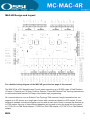
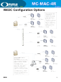
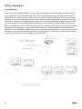
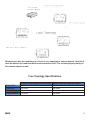
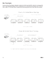
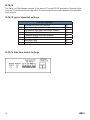
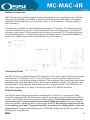
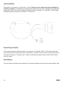
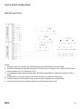
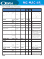
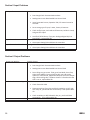
MC-MAC-4R
Hardware Installation Guide
REV 2.0
May, 2013
Table of Contents
Chapter 1: The MAC-4R......................................................................................................................................... 5
MAC-4R Design & Layout........................................................................................................................................ 5
Compatible Readers................................................................................................................................................ 6
Installation Considerations....................................................................................................................................... 6
Wire Terminations.................................................................................................................................................... 7
Network Cable Guidelines....................................................................................................................................... 7
Chapter 2: Wiring Topologies............................................................................................................................... 9
MASC Configuration Options.................................................................................................................................. 9
Free Topology Star................................................................................................................................................. 10
Free Topology Loop................................................................................................................................................ 11
Bus Topology.......................................................................................................................................................... 12
Doubly Terminated Bus Topology........................................................................................................................... 12
Singly Terminated Bus Topology............................................................................................................................. 12
Bus Topology, Specific Rules................................................................................................................................. 13
SLTA-10 Settings.................................................................................................................................................... 14
Chapter 3: Connections........................................................................................................................................15
Network Connection............................................................................................................................................... 15
Connecting Power.................................................................................................................................................. 15
Panel Grounding.................................................................................................................................................... 15
System Battery....................................................................................................................................................... 17
Panel Tamper Switch.............................................................................................................................................. 17
RAM Battery........................................................................................................................................................... 17
Card Readers..........................................................................................................................................................18
Panel Provided Power............................................................................................................................................ 19
Typical Door Wiring................................................................................................................................................ 19
Auxiliary Outputs.................................................................................................................................................... 20
Panel Wiring Layout................................................................................................................................................21
Typical Switch Hookup........................................................................................................................................... 22
Chapter 4: Panel Guidelines and Information.................................................................................................... 23
Chapter 5: Troubleshooting Guide...................................................................................................................... 25
Chapter 6: Quick Start Guides..............................................................................................................................29
Installing and Configuring the MASC Server Software............................................................................................29
Installing MAC-4R Drivers...................................................................................................................................... 29
Installing the Driver for the Echelon LT-USB Adapter............................................................................................. 30
Installing the Hardware Driver for the iLon-10 (LT-EA-10) Adapter........................................................................ 30
Adding a MAC-4R Driver........................................................................................................................................ 31
Adding Control Panels............................................................................................................................................ 32
Turn Driver On-Line................................................................................................................................................ 32
Set the Address of the Controller............................................................................................................................ 32
MAC-4R Design and Layout
For a detailed wiring diagram of the MAC-4R got to the last page of this manual.
The MAC-4R is a PLC based Access Control panel supporting up to 52,000 cards, 4 Card Readers,
16 Inputs, 8 Outputs and 16 Open Collector Outputs. It uses the Echelon Free Topology transceivers
to communicate and features full Drag-n-drop ladder logic programming.
All communications is over an Echelon Free Topology 78kb network.A single termination bus can
support up to 63 devices on a single pair of wires with a maximum distance or 400 meters. If more
distance is needed, a double termination can be used at each end of line to increase the distance up
to 2700 meters. Any one of three different adapters can be used to bring the signal into the computer; LT-SA-10 Lon-Talk Serial Adapter, LT-USB Lon-Talk USB adapter, or LT-EA-10 Lon-Talk Ethernet
adapter.
REV 2.0
5
COMPATIBLE READERS:
The MAC-4R controller supports many different styles of Wiegand based readers. The bit structure
can vary to support 26, 29, 32, 34, 35, 36, 37, 40, and 48 bits cards. Multiple formats are support
simultaneously. The following readers were determined to be compatible with the MAC-4R Intelligent
Controller.
HID Inc:
Proxpro, Proxpro with 8-bit burst keypad, Proxpoint, Proxpro Plus, Prox80, Thin
line, MiniProx, Maxiprox, Iclass versions: R10, R30, R40, RK40, R90, and Fips model C.
Idteck: RF Tiny, RF10, RF20, RFK101, RFM50, RF30, RF70
Indala Corp.: 610, FP506/507, 603, 620, ASR-505, ASR-503 proximity card readers
Mercury Security Corp.: Models MR-10 magnetic card reader.
Essex Electronics Inc.: Model K134K Keypad.
Sagem Morpho, Inc.: TWIC Readers
Core Street: FIPS solutions
Wiegand: Classic 310, 315, 314, and 312
All of the above readers have no decision making capabilities. They forward the card information to
the MAC-4R controller which makes all decisions through distributed intelligence.
INSTALLATION CONSIDERATIONS:
1. MINIMUM SYSTEM CONFIGURATION:
A. One Model MAC-4R Intelligent Controller.
B. One reader.
C. One 18-24 VAC or DC Power supply
D. One Echelon Network interface, LT-SA-10, LT-USB, LT-EA-10
E. One MASC server package: Server 1, 2, or 3
2. The MAC-4R System is intended to be installed in accordance with the Manufacturer’s Installation Instructions and the following.
A. The National Electrical Code, NFPA 70.
3. The MAC-4R Intelligent Controller is only intended for use with a UL Listed Class II transformer rated 16.5-18 VAC, 40 VA, 60 Hz or UL listed Class II 18-24 VDC power supply.
The MAC-4R Controller can provide the power for up to four 5 or 12 VDC readers. The base power
draw on the controller is 250 ma. Total power output including the power for the board, 4 readers, 16
inputs, and 8 outputs should average .5 amps. It could raise as high as 1.2 amps maximum if you
decide to power motion sensors with it.
The controller supports 16 inputs that can be confgured as Normally Open, Normally closed, 2-State,
3-State, 3-State EOL, 4-State, or analog. 8 output relay contacts are provided for door locks and other devices. All the relays are Form C Single Pole Single throw individually fused at 5 amps 125 volts.
There are also 16 open collector outputs used for providing ground connections for pilot relays or
LED’s.
The controller also supports a 13.5 volt battery charging circuit for trickle charging a battery. If power
fails, the controller will run from the battery at average discharge rate of 1/2 amp per hour. On average load, 14 hours of backup power will be provided with one 7 AH battery connected. The controller
monitors the main and secondary power input lines and provides AC Main power loss and low battery
alarms at the host computer. Main power alarm occurs at 15 volts or less and Low Battery alarm is
registered at 11 volts or less.
6
REV 2.0
WIre Terminations
All terminations are via plug-in connectors. All field wire connectors are screw-terminal compression
type, accepting up to #14AWG solid or stranded wire. Stranded-type wire is recommended. If solid-type wire is to be used, it is recommended that wire be no larger than #18AWG. Strip approximately ¼” of the insulation from lead wires for insertion into the connector terminal plugs. Screw terminals
clamp down onto the wires by advancing the screws in a clockwise direction. It may be necessary
to loosen each of the screws prior to panel wiring to allow ease of wire insertion. It is recommended
when tightening screws to remove the plug connector from its socket. Excessive pressure while tightening may damage the PC Board. Use care when tightening screws with plug connector inserted.
Network Cable Guidelines
Minimum Confguration
The MAC-4R uses Echelon’s LonTalk free topology transceivers to communicate between panels and
to the host computer. The network is designed to accommodate bus, star, or loop topologies or any
combination of these topologies. A single twisted pair wire is all that’s needed. LonTalk is very robust
and will operate on many different types of cable.
Performance will vary with cable type. The transmission specifcation depends on such factors as resistance, mutual capacitance, and the velocity of propagation. The system performance on the cables
listed in the table below have been tested and documented.
Cable Type
Wire Dia./AWG
R loop Ohm/km
C NF/km
Vprop % of C
Belden 85102, single twisted pair, stranded 19/29,
Unshielded, 150 degree C
1.3mm/16
28
56
62
Belden 8471, single twisted pair, stranded 19/29,
Unshielded, 60 degree C
1.3mm/16
28
72
55
Level IV 22AWG, twisted pair, typically solid & Unshielded
0.65mm/22
106
49
67
JY (St) Y 2x2x0.8, 4-wire helical twist, solid, shielded
0.8mm/20.4
73
98
41
It should be noted that shielded data cable is not required. If shielded data cable is to be used, the
shield wire should only be terminated at one end of each wire segment. If shielded cable is used the
distance limitation is reduced by approximately 50%.
Field Device Cable Specifications
Device TypeCable TypeMax Length
Readers
22/6 shielded Stranded
500’
Inputs
22/2 stranded 1000’
Glass Breaks, PIR, REX
22/4 stranded
1000’
MagLock
18/2 stranded
1000’
Electric Strikes
18/2 stranded
1000’
Panel power
18/2 stranded
100’
REV 2.0
7
MASC Configuration Options
REV 2.0
9
WIring Topologies
Free Topologies
When using free topology cabling, the only criteria that matters is the total length of cable. Star and
loop confgurations are both supported. As the chart below illustrates, Low impedance Cat V cable
allows for a total of 400 meters of cable in any one segment. Up to 63 devices can exist in any one
segment. If you need to go farther you can add a repeater which separates your wiring into two segments. Free Topology is terminated with a single 52 ohm resistor preferably located towards the center of the segment. Loop topology has the advantage of redundancy. If for any reason that the loop
gets cut, the network will not stop functioning unless the network has a direct short at the point where
damaged. Free topology is very forgiving and may appear to work just fne without the termination
resistor, but it still important to place this resistor on the trunk-line especially on very short or very long
distances to ensure good data fow and avoid network collisions. The Echelon communications line is
not polarity sensitive. Several examples are provided here.
10
REV 2.0
Whenever you wire the controllers in a loop it is very important to observe polarity. Host Net A
must be attached to A and Host Net B must be attached to B. This includes proper polarity on
the network adapter as well.
Free Topology Specifications
Maximum distance between any two nodes. Maximum total wire length per segment.
Belden 85102
Belden 8471
Level V,22AWG
JY (St) Y 2x2x0.8
REV 2.0
500 meters
400 meters
400 meters
320 meters
500 meters
500 meters
500 meters
500 meters
11
Bus Topologies
If a more robust long distance network is required a double terminated Bus network is recommended.
With a 16-2 twisted pair (Belden 85102 or equivalent) you could extend your network up to 2700 meters or 8800 ft. A 105 ohm resistor is placed at the extreme physical end of each end of the network.
12
REV 2.0
Buss Rules and Limitations
In a doubly terminated bus topology, two (105 ohm resistors) terminations are required, one at each
end of the bus. Control Panels connected to the bus must not have more than a 3-meter stub length.
The Lon-Talk Serial adapter is just another node on the network so it can be located anywhere on the
bus. Doubly terminated bus confgurations do not have a maximum node-to-node distance, so you
could have one controller 1,000 meters away from 10 controllers in another area of the building. The
same rules apply to bus terminations as there are only 63 devices allowed per segment. At this time
the cable is fully loaded, to expand it a repeater must be added.
Double Terminated Bus Specifications
Belden 85102
Belden 8471
Level V,22AWG
JY (St) Y 2x2x0.8
REV 2.0
Maximum bus length for segments with Free topology
transceivers wired as double terminated bus.
2700 meters
2700 meters
1400 meters
900 meters
13
SLTA-10
The Serial Lon-Talk Adapter connects to the server PC via an RS-232 connection. Distance limitations are 50’ maximum with low cap cable. All communications are verifed between the controllers
and computer.
SLTA-10 typical dipswitch settings
1
2
3
4
5
6
7
8
Switch Settings
Buffered Link/ Alert Ack. protocol
Remote Host/ Local Host
Net disables after reset/ Net Always Enabled
NSI Firmware/ SLTAFirmware
Autobaud Enable/ Autobaud disabled
Baud rate 19,200
Baud rate 9,600
Baud rate 2,400
Off
Off
Off
Off
Off
On
Off
Off
SLTA-10 Side View Switch Settings
14
REV 2.0
Network Connection
MAC-4R panels are connected together for data communication over a twisted-pair cable. The twisted pair may be shielded or unshielded. It should be noted that shielded data cable is not required.
Termination for this data line is via J1 terminals 5 and 6. It is not necessary to observe polarity for
data line hook-up.
If the data line is shielded, the shield should be terminated to J1 terminal 4. The shield wire should
only be terminated at only one end of each wire segment. Also note that terminal J1 pin number 3
connects to earth ground. This connection must be made to insure the RTU PC board has the proper surge discharge path. It is recommended that the terminating resistor if required be installed as
shown in the diagram below to avoid being shorted over years of service.
Connecting Power
The MAC-4R can be powered through an AC transformer or DC power supply. The main power leads
are connected to J1 terminals 1 and 2. If using a DC power supply the positive lead needs to be
wired to terminal 1 (top) and the ground to terminal 2. The base draw of the control panel with nothing
connected except the power lead is 150ma. 50ma would be added per reader, 15 ma per input, and
40ma per output. When sizing the power supply provide 1 amp per controller. The PWR-24 is a 24
VDC power supply rated at 2.5 amps. It has enough power for (2) MAC-4R controllers.
Panel Grounding
The MAC-4R panel should be grounded by connecting the J1 terminal 3 to earth ground. When
mounted in a standard MAC-4R enclosure box, there is a ground lug located at the bottom middle of
the box. The PC board should be connected to this ground lug. The installer should always insure
the enclosure box is earth grounded at the nearest building ground point. Earth grounding the
enclosure provides a discharge path for power surges and ESD. An electrical circuit ground is not
an acceptable ground path. The ground should be to a ground rod, building steel or other true
ground source. The ground wire should be min 12 AWG wire and be kept as short as possible. connecting power to the MAC-4R.
15
REV 2.0
System Battery
The battery is connected to J2 terminals 1 and 2. Polarity must be observed when installing the
12-Volt sys battery. If connected incorrectly system backup will not work. Damage to the panel and
battery may result. The positive battery terminal must be connected to J 2 terminal 1, and the negative battery terminal must be connected to J 2 terminal 2.
Panel Tamper Switch
The enclosure tamper switch terminates on connector J2 terminals 3 and 4. The switch should be
wired to that when the enclosure door is closed shut, the switch is then in the closed contact position.
The switch is wired as “normally open”. Figure 4 indicates the tamper switch’s state with the enclosure door open.
Ram Battery
The ram battery provides memory backup in the event all system power and the system battery fails.
16
REV 2.0
Card Readers
The MAC-4R support up to (4) wiegand output readers. The panel default is set to a standard 26
bit format, but can be changed to support any format up to 48 bit codes in the software. If PIN’s are
required, the panel supports the 8-bit burst keypad. The installer should follow the card reader manufacturer’s recommendations for wire-type, gauge, and shielding. Cabling should be an independent
run of shielded cable with shields tied to ground at controller location.
A valid card read will toggle LED1 for the pulse time set on the Reader Settings Tab.
LED2 is optional, many people use it to control a beeber.
REV 2.0
17
Panel Provided Power
The MAC-4R panel uses a switch-mode regulator for the 12-Volt power supply. Some card readers
and other device manufactures indicate in thier documentation that their products should be powered
from a linear power supply. Of those tested with the MAC-4R, we have not encountered any problems. The internal 12-volt supply is well filtered and has low ripple or noise.
The MAC-4R provides 5 VDC and 12VDC power via the Card Reader connections and 12VDC power
on connector block J13. Up to 750ma @ 12VDC and up to 500ma @ 5VDC of power for powering
card readers and other peripheral devices. This power is in addition to the 230ma used by the 16 input points per panel. There are certain long-range type proximity readers that may require a separate
external power supply is more power is needed. If a separate power supply is used, power supply
commons must be connected for proper operation. Also, when powered from a separate soure, battery backup for those devices must be provided.
Typical Door Wiring
Locking hardware is not directly powered from the control panel. You can use the 24VDC power supply powering the control panel if it supplies separate fusing. If controlling a magnetic lock or remote
gate with a pilot relay we also recommend installing a reverse bias suppression diode across the coil
of your pilot relay.
18
REV 2.0
Auxiliary Outputs
The MAC-4R panel has 8 high-level door control relays and 16 open collector solid-state outputs to
provide ground path. The open collector outputs rated for 125 ma @ 30 volts DC (J14). Each door
control relay is rated for 6 amps @ 300 volts AC with form “C” type contacts protected by 5 amp @
125 volts AC user replaceable fuses. Relay contacts are electrically isolated from other circuits.
The Open Collector outputs provide a path to ground. Options include driving LED’s or controlling
pilot relays. If controlling LED’s you can use the 5VDC power from the Reader Terminal blocks run it
through a 1K resistor and back to the MAC-4RTTL to pick up ground. If controlling pilot relays select
the right power source 5 or 12 VDC and wire the ground path through the MAC-4R-TTL board.
The 16 Open collectors can be programmed like any other output and are addressed as Outputs
9-24. By default these points are not programmed to respond. To turn them ON go into System Design, expand the Output branch on the RTU, go to the property page of the outputs you want to use
and Select,√ RTU will transmit. A Settings Download is required after the change in programming.
REV 2.0
19
Diagnostic LEDs
The MAC-4R panel has 23 diagnostic LED’s which tell the Technician at a glance real time Point
Status as well as Main Power Status, Back-Up Battery in Use, Panel Transmit Status, and various
processors health.
• When the MAC-4R control panel frst powers up, you should have 2 Red LEDs ON (Power and
Transmit) in the upper left hand side of the controller. You’ll notice that the Transit LED will fash
every once in a while. It fashes off when ittransmits to the Host computer. Upon boot, if no prior
confguration has been detected, the controller will run through a Power ON Ram Test. The Host
computer should receive two RAM Pass messages: one from P1 and the other from P2.
• If any of the Green Service LEDs are ON for processors P1 (D38), P2 (D37), P3 (D14), or P4
(D15) it’s bad news. There are three check sums that have to match for the processor to boot and
go on-line. The most common problem is static electricity discharge knocking out a ROM chip. If
this occurs, call the factory for help.
• The Yellow LED (D50) will only come on if the control panel is running at a voltage less than
14VDC. Minimum voltage specifed is 18 volts. When the controller gets down to fewer than 11
volts the low battery cut of relay disconnects the controller from battery power.
• The LEDs across the bottom of the control panel provide real-time point status. If the LED is ON,
the point is closed. When a new controller is powered up, the address of the control needs to be
set and an initial download of Settings must be transferred into the controller before it will start
transmitting input or output status to the Host computer.
20
REV 2.0
Typical Switch Hookup Detail
MAC-4R Control Panel
Notes:
1. All switch inputs are shown open and assumed to be held closed for secure state.
2. Total wire resistance should be kept below 100 Ohms for all 2 state circuits. Typical 22 AWG wire
has a resistance of 16.5 Ohms per 100 ft.
3. It is suggested where longer lengths than 5000 ft are required the conductor be sized at 18/2 or
larger.
4. 2 state wiring is the most common but does not allow for conductor supervision.
5. 3 state hookups provide switch status as will as near complete circuit supervision.
6. 4 state hookups provide complete supervision of all states of the circuit.
REV 2.0
21
Panel Guidelines and Information
MAC-4R
Typical
Minimum
Maximum
Operating Voltage
16.5-24
VDC or
AC
16.5 VDC
30 VDC
140 ma
190 ma
30 ma
70 ma
Operating Current Base
Panel
Readers
Input Voltage
5 or 12
VDC
0-12
VDC
Input Current
Output Fusing
12-125
VAC
Output Current
10 ma
12 ma
0 VDC
125 VAC
15 ma
41 ma
78 KB
78 KB
78 KB
Memory Backup
18
months
12 months
24 months
Operating Temp
Operating Relative
Humidity
Field Wire Termination
10-40 C
40%
-40 C
0
+50 C
95%
18 AWG
24 AWG
14 AWG
Field Wire Terminal
Voltage
Field Wire Terminal
Current
Load Voltage
0-30
0 VDC
VDC
0-5 amps 0 amps
125 VAC
15-28
VDC
0 Volts
125 VAC
250 ma
5 ma
5 amps
REV 2.0
All
Remarks
Points
On
DO NOT exceed maximum operating voltage.
Measured at typical operating voltage. At maximum voltage maximum
current =1.20 amps
40 ma 160
ma
.012 mVDC 15 VDC
Data Communications
15 VDC
Load Current
One
Point
On
5 amps
12 ma 192
ma
36 ma 288
ma
Dry Contact switching
only.
Dry Contact switching
only.
Dry Contact switching
only.
Dry Contact switching
only.
Standard operation is 78
KB. Special router will allow up to 1.25 MB operation internal to rack.
10 year shelf life maximum. Memory backup
duration is dependent on
RAM version used.
Non-condensing
Solid or stranded.
Stranded is recommended.
Maximum terminal rated
voltage 125 VAC.
Maximum terminal rated
current 5 amperes.
Current through load
switching relay contacts.
23
MAC-4R Troubleshooting Guide
Sections
1. Power Problems
2. No Communications
3. Basic Processor Operation
4. Readers and Card Problems
5. Input Problems
6. Output Problems
Section 1 Power Problems
Is PWR led (D20) on?
• Check incoming voltage on J1, Pins 1, 2. Power should be
minimum of 16.5 v. and not over 28v AC or DC
• If DC voltage Positive terminal needs to on Pin 1
Aux 12v Power on?
• Dead short in field, the positive 12v from control panel has
dead short to earth ground somewhere. Disconnect all
terminal block except for main power, remove battery and
cycle power. Did led (D20) come on? If not replace MAC4R-PCB. If yes, continue
• Check terminal blocks J12, Pin 4; J3 Pin 4; J11 Pin4; J4
Pin 4; and J13 Pins 1-4 Voltage should be at 12-13.5 vdc
• Check terminal blocks J5, Pin6; J6, Pin 6; J9, Pin 6; J10
Pin 6 voltage should be at 12-13.5 vdc
• Dead short in field, the positive 12v from control panel has
dead short to earth ground somewhere. Disconnect all
terminal block except for main power, remove battery and
cycle power. Did power return to all pins? If not replace
MAC-4R-PCB. If yes, continue
Check Ground?
Check Battery?
• Plug field wire in one terminal block at a time until power
drops out again. Repair field wire and repeat this step.
• Take a VOM (set on continuity) and check J1, Pin 3 to
Earth or structural ground. Meter should show continuity.
• Check terminal block J2 Pin 1, it should be 13.5 volts dc.
• Could have a bad Gel Cell battery, Disconnect Gel Cell
battery from MAC-4R, measure again. Did voltage come
back? Yes, Continue
• With battery disconnected take voltage reading across
battery terminals, voltage should measure 12vdc, if not
replace battery.
REV 2.0
25
Section 2 No Communications
Is Xmit led (D4) on or
flashing?
Is Driver Service
Loaded?
Is Driver status Double
Green?
• It should be, If not, could have processor problem, go to
Section 3
• No, Load and configure Driver Service
• Open the Driver service on the Host Computer by right
clicking on the Double Green box in the system tray, Select
Open.
Top icon represents Host Connection, Lower box represents
Network connection.
• Green, connection established.
• Blue represents Off-Line, Right click and turn it On-Line
• Red, Top -Panel on Domain not found in Host computers.
The driver service cannot find a panel in the DB for the
Domian set in Driver Service.
• Red, Bottom – PC Port for Echelon adapter not found,
RS232, USB port, or IP port does not exit on this
computer.
• Yellow, bottom – Timeout, Panel ID might not be set.
• Driver must show Green on top and on either yellow or
green on bottom to continue.
Is MAC-4R Address Set?
• Test connectivity by opening MAC-4R RTU and hitting
the service pin of the control panel. If cable and driver are
working a message should pop up stating that the System
has just received a new Neural ID, Do wish to use this
ID for this control panel? Did the message come up, Yes
continue. If no, check cable
• Accept the new Neural ID, Hit Apply, and Load Device
Address. To test send a “Clear All” you should receive two
events back, P1 Ram Pass and P2 Ram Pass, If you did
not receive these continue
View Driver Messages
26
• Perhaps the Hardware Domain is set to the wrong
address. Use NodeUtil to view the panel address and
domain.
• While downloading Settings to a control panel open up
the Driver, Messages display, you should be averaging 6
commands per second with an ACK after each message. If
not you have a wiring problem.
REV 2.0
Section 3 Basic Processor Operation
Are there any Green Led’s
(D38, D37, D14, D15) lit
around the processors?
Send “Clear All” to Control
Panel
Send Setting to Control Panel
Send Cards to Control Panel
• If yes, The control panel has lost it’s firmware, Send the control
panel back to factory. If no Continue.
• Send a “Clear All” you should receive two events back, P1 Ram
Pass and P2 Ram Pass. P1 should come in right away and P2
should come in within 30 seconds. If you only received one
event from P1 and nothing from P2 or if you received Ram Fail
replace MAC-4R. If OK Continue. If you received both back as
Ram Pass events your processors are working.
• The Setting tab includes all basic operation of MAC-4R
• Allow the system at least 10 minutes for a card download. The
system averages 6 cards per second on a card download.
Section 4 Readers and Card Problems
No Card Reads or Wrong card
number
Open the Monitor Events tab found in the Alarm Que
• Does Reader Beep? No check Power, Yes Continue
• Wrong kind of Card
• Wrong Bit Pattern, Set on Reader Setting Screen, You must
download Settings of you change this.
Card Not in Host DB
Card not in DB
Card Not Assigned
Valid Read
REV 2.0
• Bad Ground causing memory to be corrupt. Send a Clear All and
download Setting again.
• Right click on card event in Alarm Queue and select Card
Lookup, if not found in Host check Host card number for leading
0’s or leading spaces. Proper setup would not have any leading
0’s or spaces.
The Card number was not found in the control panel.
• Check the Access Level, Exp Date and open message window to
make sure card is being send to control panel.
The card is in the Control Panel but the Access Level doesn’t not include
the door selected.
• Check the Access Level and Door Group
If you get a Valid Read but the door does not unlock check the Monitor
Events screen for Relay On and Off. If you do not see the Relay go On
and Off, Your Ladder is not working and needs to be downloaded to the
control Panel, Check the ground and download Settings.
27
Section 5 Input Problems
No Input Events
Possible Causes
• Run though Check Communications above
• Settings were never downloaded into Control Panel
• Input Properties Screen, Operation Tab, RTU transmit must be
selected.
• Set to wrong type of input; 2-state, 3-state, 4-State etc..
• Check Led for input, Led needs to follow state, Led On is closed,
Led goes off is Open.
Input Reversed
• Look for A/D Fail Alarm, if yes your Analog to digital chip has
been blown, replace MAC-4R
Input reports as Open when Closed and Closed when Open
Input Alarm when Closed
• Goto Inputs Setting Tab and Select the Invert Box
Input goes into Alarm when the door closes
• Goto Inputs Setting Tab and Select the Invert Box
Section 6 Output Problems
Output not Working
Possible Causes
• Run though Check Communications above
• Settings were never downloaded into Control Panel
• Does LED go on, go to next. If No, go to Run Mode, show Tree,
Allow Point Settings. You may have to edit user and set this
option on. In Run mode, Expand RTU Outputs and Force Output
High, LED should go On, If software shows it’s forced on but the
LED is not on, replace MAC-4R
Led on but Device not Tripped Possible Causes
• Check Fuse with VOM
• Disconnect wiring from relay and check continuity on N/C side
with relay off, you should have connectivity. If not replace MAC4R
• Check continuity on N/O side with relay on, you should have
connectivity. . If not replace MAC-4R
28
REV 2.0
Quick Start Guide for Installing MASC
Installing and Configuring the MASC Server Software
1. Install the MASC Software on the Server. Make sure to select the following options:
a. Install as Server
b. Add Drivers, Select MAC-4R Series
c. Projects to Copy, No
2. The frst time you load MASC the software will ask some configuration questions. Execute the
MASC desktop icon from the desktop.
a. MASC Program Loader, This is asking which modules to run. Keep Server,
DriverService and Workstation and hit OK.
b. There are (3) screens upon each other. Move the screens around so you can get to the
Server Registration Screen. Keep Defaults and Hit OK.
c. The Server License screen will pop-up. It shows the MAC address of the last network
adapter installed on the server. To register the software, do a Alt-Print Screen and paste
it in MS Paint. Save it as a .jpeg and email it to OSSI to get your License Number. In the
meantime, hit Cancel and the program will still load and be fully functional for two hours.
You can program your system. If you run out of time exit all three modules of MASC; restart it and you’ll have another 2 hours.
d. On the MASC Workstation Registration Screen, Hit OK to accept all defaults. The User
name is master and the password is m. You are now ready to program your system.
Before you can actually turn your driver communications ON you need to have some
control panels in your database.
Quick Start Guide for Installing MAC-4R Drivers
If the install requires the use of the Echelon USB adapter (LT-USB), or iLon-10 adapter (LT-EA-10)
then follow the next few steps to install the hardware drivers before you attempt to install the MASC
MAC-4R driver. These two adapters require the proper Open LDV hardware drivers before the MASC
Driver can be installed.
SLTA-10
LT-USB
LT-iLon-10
Lantronix to SLTA
REV 2.0
RS232 Serial Port
Open LDV Port
Open LDV Port
TCP/IP Port
29
Installing Driver for Echelon LT-USB Adapter
1. Insert the CD that came with you USB adapter leaving the USB adapter unplugged. This will
install the hardware filesrequired to support the USB adapter.
2. Upgrade to Open LDV version 3.4. Go to the MASC CD and open the OpenLDV subdirectory.
Execute the OpenLDV340exe file and follow the prompts to install Open LDV.
3. Now plug the LT-USB adapter into an open USB port. If this is the first USB adapter this
computer has loaded it will be assigned to port “Lon1”. The PC now has all the information to
properly load the new MASC drivers. If there are any problems with this go to Start, Control
Panel, LonWorks Interfaces. Under the USB tab (with the USB adapter plugged in) you should
have a network port called LON1.
Installing Hardware Driver for iLon-10 (LT-EA-10) Adapter
1. Install and insert the CD that came with the iLon-10 adapter. Execute the setup.exe file, follow the prompts and the
CD will install the hardware drivers required to support the devices.
2. Upgrade to Open LDV version 3.4. Go to the MASC CD and open the OpenLDV subdirectory. Execute the
OpenLDV340 exe file and follow the prompts to install Open LDV.
3. The PC will need to be set to a compatible IP address to 192.168.1.xxx, Subnet 255.255.255.0.
4. Now plug is the LT-EA-10 (iLon-10) adapter into a network port. Using Windows Internet Explorer set the iLon’s IP
address of the iLon-10 to an IP address compatible with the network you need to run on. It needs to be something
other than the default address of 192.168.1.222
a. You connect to the device in Explorer with http://192.168.1.222/confg
b. User name ilon, Password ilon
c. If any free software display, make sure to allow connections for that device.
d. Change the IP address in the IP address field
e. Set the Subnet Mask to something compatible with the network it will run on. Most networks are set at
255.255.255.0
f. Scroll down and click Submit
g. To verify the changes have been down properly you can click on the provided link to connect to the adapter
again or go to the next step.
30
REV 2.0
5. Add the device as a piece a hardware in Lonworks Interfaces.
a. Go to Windows Control Panel, Lonworks Interfaces, Remote Network Interface (RNI) tab and add your
hardware. This is where the driver will find the IP address of the network interface.
b. Highlight “Default” on the base tree, Click on Add button.
c. Specify a name for the device. This name will automatically be given a prefix you will not be able to change.
You could name the device after the last number on the IP address or perhaps the building name. For
example if you name it 111, when you add an OpenLVD driver in MASC you would select “x.default.111”
from the picklist.
d. Network Manager select “Other”.
e. Enter the new IP address of the iLon-10.
f. Click Finish.
g. Highlight the XDefault name and click “TEST” Function.
h. Click Start. If everything worked the last line of the procedure will provide Success.
Adding a MAC-4R Driver
1. To add a MAC-4R driver, right click on the double green set of boxes in the system tray. Select
Open. This screen diplays all the drivers installed for the system. If you have not installed any drivers, this
screen will be blank.
a. On the MASC Driver Configuration Screen, Select Add, when prompted, select MAC-4R series. Select the
proper Communications Type: RS232, IP, or Open LDV. If you have a Echelon USB or iLon-10 adapter
select Open LDV.
b. A configurations screen will appear. Select the proper port. If adding a Serial port, go to the 232 tab and
select the proper com port. If adding an OpenLDV device, go to the OpenLVD tab and select the proper
OpenLDV port. Lon1, Lon2, X.Default.xxx.
c. Go to the Driver tab and provide a unique domain number. The default is 40. This number can be any
number between 1-255. The Domain number is cross referenced to the Domain field on the MAC-4R RTU
screen.
d. Driver Tab, Make sure the Net feld matched the Echelon subnet of the MAC-4R panels you wish to
communicate to.
e. Accept the default entries for the rest by hitting OK.
f. Upon creating a new port, the system adds the new port in the off-line state (Blue Icons). If you’re ready to
talk with these controllers, right click on the driver and select on-Line. If you do not have any controllers in
your database for this port leave the driver port off-line until after you add controllers and are ready to talk
to them.
REV 2.0
31
Add Control Panels
1. Add the control panels into the database by right clicking on a Site and selecting “Add Node”.
2. Open the new controller and make sure the Domain and Net numbers match the port the
control panel is assigned to.
3. Name the Controller; we suggest using the building name followed by the Net, Node address.
Pederson 2-1 etc. Hit Apply.
4. Take the virtual flag off, Hit apply. The panel name will show up in the Alarm que as Off-Line as
the Server is now trying to communicate with the controller.
Turn Driver On-Line
1. After adding the Controllers to the database and communication wires are installed, you’ll have to open the
DriverConfguration Screen to turn the port on-line.
2. Right click on the double green set of boxes in the system tray. Select Open. This screen displays all the drivers
installed for the system.
3. Right click on the double blue squares for the port in question and select On-Line.
4. If communications are established to the server the top icon will be green. The lower icon shows the status for
connecting to the port. If it turns green, you are talking to the port. If it turns yellow, the system is timing out, it found
the port but cannot find the Echelon adapter. If it turns red the system cannot connect to the port.
Set the Address of the Controller
1. By default a control panel is shipped at address (1.120). When you add a new controller to the database the
controllers start at Net/Node address 1.1. and move up from there. To set a panels address the MASC software
needs the unique neural ID of the panel you are trying to set.
a. Open the RTU screen of the panel you wish to set and Hit the service Pin.
b. The system will display a popup window saying, “A new neural ID has been received, do you wish to use it”.
Select Yes.
c. Hit apply to save the changes.
d. Hit Load Device Address.
e. Use the “Set Date and Time” to test communications. If all worked properly you should not see a panel OffLine alarm in the Alarm Que.
f. Download the Settings and cards to the Control Panel.
32
REV 2.0