1
User's Manual
EPSON ®
Y45499114003
®
EPSON
LQ-850/950/1050
User's Guide
FCC COMPLIANCE STATEMENT
FOR AMERICAN USERS
This equipment generates and uses radio frequency energy and if not installed and used
properly, that is, in strict accordance with the manufacturer’s instructions, may cause
interference to radio and television reception. It has been type tested and found to comply
with the limits for a Class B computing device in accordance with the specifications in
Subpart J of part 15 of FCC Rules, which are designed to provide reasonable protection
against such interference in a residential installation. However, there is no guarantee that
interference will not occur in a particular installation. If this equipment does cause interference to radio or television reception, which can be determined by turning the equipment off and on, the user is encouraged to try to correct the interference by one or more of
the following measures:
- Reorient the receiving antenna
- Relocate the printer with respect to the receiver
- Plug the printer into a different outlet so that the printer and receiver are on different
branch circuits.
If necessary, the user should consult the dealer or an experienced radio/television technician for additional suggestions. The user may find the following booklet prepared by the
Federal Communications Commission helpful:
“How to Identify and Resolve Radio-TV Interference Problems.”
This booklet is available from the U.S. Government Printing Office, Washington, DC
20402. Stock No. 004-000-00345-4.
WARNING
The connection of a non-shielded printer interface cable to this printer will invalidate the
FCC Certification of this device and may cause interference levels which exceed the limits
established by the FCC for this equipment, If this equipment has more than one interface
connector, do not leave cables connected to unused interfaces.
All rights reserved. No part of this publication may be reproduced, stored in a retrieval system,
or transmitted, in any form or by any means, mechanical, photocopying, recording or otherwise, without the prior written permission of Seiko Epson Corporation. No patent liability is
assumed with respect to the use of the information contained herein. While every precaution
has been taken in the preparation of this book, Seiko Epson Corporation assumes no responsibility for errors or omissions. Neither is any liability assumed for damages resulting from the
use of the information contained herein.
Apple is a registered trademark of Apple Computer, Inc.
Centronics is a registered trademark of Centronics Data Computer Corporation.
Epson is a registered trademark of Seiko Epson Corporation.
IBM is a registered trademark of International Business Machines Corporation.
Copyright 0 1988 by Seiko Epson Corporation
Nagano, Japan
Contents
About This Guide
Introduction
Chapter 1
Setting Up the Printer
Unpacking the Printer
Checking the parts
Removing the protective materials
1-2
1-2
1-3
Choosing a Place for the Printer
1-5
Assembling the Printer
Installing the platen knob
Installing the ribbon
Attaching the paper guide
1-6
1-6
l-7
l-10
Testing the Printer
Loading a sheet of paper
Running the self test
1-12
1-12
1-15
Connecting the Printer to Your Computer
The parallel interface
The serial interface
1-18
1-19
1-20
Chapter 2
Paper Handling
Using Single Sheets
Reloading during printing
2-2
2-5
Using Continuous Paper
Positioning your continuous
paper supply
2-6
2-11
Switching Between Continuous and
Single Sheets
Switching back to continuous paper
2-12
2-15
...
111
Contents
Printing on Special Paper
The paper thickness lever
Multi-part forms
Labels
Envelopes
Chapter 3
iv
2-16
2-16
2-18
2-18
2-19
Using the Printer
Operating the Control Panel
Lights
Buttons
SelecType
Other control panel features
3-2
3-2
3-3
3-4
3-5
Setting the DIP Switches
3-6
Page Length
3-9
Skip Over Perforation
3-10
Adjusting the Loading Position
The loading position
Micro adjustment
3-12
3-12
3-12
Short Tear Off
3-14
Selecting Typestyles
Character fonts
Character pitch
Condensed mode
If SelecType does not work
3-16
3-16
3-16
3-16
3-19
Selecting Character Sets
Choosing an international character set
Choosing a character table
3-20
3-20
3-20
Contents
Chapter 4
Software and Graphics
Software
Choosing from a menu
A quick test
Computer-printer communication
Word processors
Spreadsheets
Graphics programs
4-2
4-2
4-3
4-3
4-4
4-6
4-7
Graphics
The print head
Graphic command
Column reservation numbers
First graphics program
Using hand-calculated data to
print graphics
Individual graphics options commands
Reassigning command
4-8
4-9
4-12
4-13
4-14
User-Defined Characters
Designing your characters
Sending information to the IQ
Printing user-defined characters
Copying ROM characters to RAM
Letter Quality characters
4-20
4-20
4-24
4-27
4-27
4-28
Chapter 5
4-14
4-18
4-19
Maintenance
Replacing the Ribbon
5-2
Transporting the Printer
5-4
Cleaning the Printer
5-6
Chapter 6
Troubleshooting
Troubleshooting
Problems and solutions
Data dump mode
6-2
6-2
6-5
Contents
Chapter 7
Using Printer Options
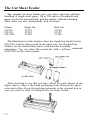
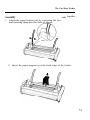
The Cut Sheet Feeder
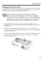
Assembly
Installation
Setting the sheet feeder mode
Recommended paper
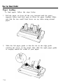
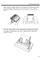
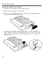
Paper loading
Envelope loading
Using the cut sheet feeder
Software operation
Setting up your software
Control panel operation
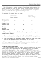
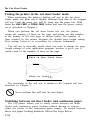
Testing the printer in the cut
sheet feeder mode
Switching between cut sheet feeder
and continuous paper
7-2
7-3
7-4
7-7
7-7
7-8
7-10
7-11
7-11
7-12
7-14
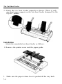
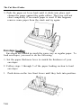
The Pull Tractor
Installation and use
When you are finished printing
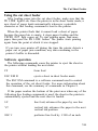
Using the pull tractor alone
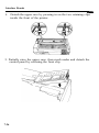
Removing the pull tractor
7-16
7-17
7-22
7-22
7-23
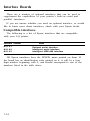
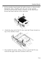
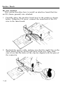
Interface Boards
Compatible interfaces
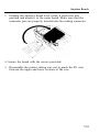
Installing the interface board
7-24
7-24
7-25
The Multi-Font Module
Using the font module
7-34
7-36
The Emulation Module
7-38
Chapter 8
7-15
Technical Specifications
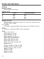
Printer Specifications
Printing
Paper
Mechanical
Electrical
Environment
vi
7-14
8-2
8-2
8-3
8-4
8-5
8-5
Contents
Interface Specifications
Parallel interface
Serial interface
Chapter 9
8-6
8-6
8-9
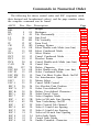
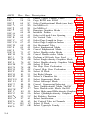
Command Summary
The Command Summary
9-2
Commands in Numerical Order
9-5
Commands Arranged by Topic
Printer operation
Data control
Vertical motion
Horizontal motion
Overall printing style
Print size and character width
Print enhancement
Word processing
Character tables
User-defined characters
Graphics
9-8
9-8
9-13
9-13
9-18
9-22
9-23
9-26
9-3 1
9-32
9-33
9-36
Glossary
Index
Vii
About This Guide
This User’s Guide provides step-by-step instructions on setting and
operating the LQ-850, LQ-950, and LQ-1050 printers.
Finding your way around
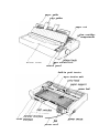
Chapter 1 contains information on unpacking, setting up, and
testing the printer, so be sure to read and follow the instructions in
this chapter first. Inside the back flap of the guide are illustrations
of the printer with all of the major parts identified.
Chapters 2 and 3 include important information on paper
handling and general printer operation. This information is
necessary for the day-to-day operation of your printer.
Chapter 4 contains information designed to help you get the most
from your printer. This section includes advice on the use of
applications software, graphics, and user-defined characters.
Other chapters include information on troubleshooting, printer
options, and general maintenance. You will also find a glossary of
printer terms and an index.
At the back of the manual is a Quick Reference Card with the
information you are most likely to need.
The LQ-850, LQ-950, and LQ-1050 are basically the same
printer except for their widths. Therefore, the illustrations in this
guide show only the LQ-1050.
...
vu1
About This Guide
Conventions used in this Guide
Warnings must be followed to avoid damage to your
equipment.
Cautions should be followed carefully to ensure that your
printer operates correctly.
Notes contain important information and useful tips on
the operation of your printer.
ix
Introduction
The LQ-850, LQ-950, and LQ-1050 are advanced 24-pin
impact dot matrix printers, combining high performance and
reliability with a wide range of features.
Features
In addition to the high quality printing and ease of operation
you’ve come to expect from Epson printers, the LQ-850, LQ-950, and
LQ-1050 offer the following:
An advanced paper handling system that lets you use single
sheets of paper without removing the continuous paper. This
system allows you to use continuous paper even while the
optional cut sheet feeder is attached.
A new short tear-off feature that saves paper. After you tear off
the last sheet printed on continuous paper, the printer reverses
the paper so that you can use all of the next sheet.
A micro-adjustment feature that allows you to feed the paper
forward or backward in 1/180th of an inch increments to finely
adjust the loading and short tear-off positions.
Reduced noise levels.
An improved control panel design that allows direct selection of
character fonts and pitch, as well as a choice of normal or
condensed printing.
Draft mode with fast printing of up to 264 characters per
second in 12 cpi.
A Letter Quality mode for producing high quality documents.
The ability to handle a wide range of paper types. The
optional cut sheet feeder can automatically feed single sheets
and envelopes.
X
Introduction
Options
A variety of printer options are available for use with the LQ
printers. For detailed information on the installation and use of
these options, see Chapter 7.
Single-Bin and Dual-Bin Cut Sheet Feeders
The cut sheet feeders give you easier and more efficient handling of
single sheet paper. Up to 150 sheets of standard bond paper can be fed
automatically into the printer without reloading. These units also can
automatically feed envelopes.
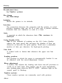
Pull Tractor Unit
This option improves the performance of continuous paper
handling. It is especially useful with continuous multi-part forms.
Optional Interface Boards
A number of optional interfaces can be used to supplement the
LQ’s built-in parallel and serial interfaces. Guidelines for choosing
the right interface and instructions on installing the boards are given
in the section on interface boards in Chapter 7.
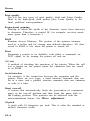
Multi-Font Module
The optional Multi-Font Module adds to the number of character
fonts available in Letter Quality mode. See the section on the font
module in Chapter 7 for more information.
Emulation Module
®
The optional Emulation Module for IBM ProPrinter X/XL24
allows you to use programs designed to be used with an IBM
ProPrinter.
xi
Introduction
xii
Unpacking the Printer
Checking the parts
Removing the protective materials
1-2
l-2
1-3
Choosing a Place for the Printer
l-5
Assembling the Printer
Installing the platen knob
Installing the ribbon
Attaching the paper guide
l-6
l-6
l-7
l-10
Testing the Printer
Loading a sheet of paper
Running the self test
1-12
1-12
1-15
Connecting the Printer to Your
Computer
The parallel interface
The serial interface
1-18
1-19
l-20
Unpacking the Printer
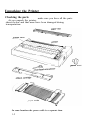
Checking the parts
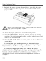
make sure you have all the parts
AS you unpack the printer,
shown below and that none have been damaged during
transportation.
In some locations the power cable is a separate item.
1-2
Unpacking the Printer
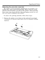
Removing the protective materials
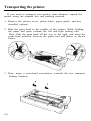
The printer is protected during shipping by two brackets, two
locking tabs, and a print head protector. These protective items
must be removed before you turn on the printer. After removing
these items, store them with the other packaging material in case
you ever need to transport your printer.
To remove the packing materials, follow these steps:
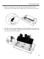
1. Remove the printer cover; then use the enclosed cross-head
screwdriver to unscrew and remove the two transport locking
brackets.
1-3
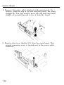
Unpacking the Printer
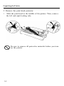
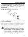
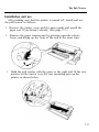
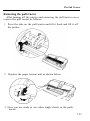
2. Remove the print head protector.
3
Slide the print head to the middle of the printer. Then, remove
the left and right locking tabs.
Be sure to remove all protective materials before you turn
on the printer.
1-4
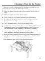
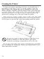
Choosing a Place for the Printer
There are several considerations in selecting a location for your
printer. Be sure to keep the following in mind:
Place the printer close enough to the computer for its cable to
reach.
Place the printer on a flat, stable surface.
Leave room for easy printer operation and maintenance.
Avoid locations that are subject to direct sunlight, excessive
heat, moisture, or dust.
Use a grounded outlet; do not use an adapter plug.
Avoid using electrical outlets that are controlled by wall switches
or automatic timers. Accidental disruption of power can wipe
out information in your computer’s and printer’s memory.
Avoid using outlets on the same circuit with large motors or
other appliances that might disturb the power supply.
Keep the entire computer system away from potential sources of
interference such as loudspeakers and the base units of cordless
telephones.
The illustration below shows a good printer location.
1-5
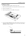
Assembling the Printer
Installing the platen knob
After you’ve decided on a location for your printer, the first step
in setting it up is to install the platen knob. You will find the knob
packed in an indentation in the white foam packing material.
1. Insert the knob into the hole on the right side of the printer.
Rotate the knob until it slips onto the shaft.
2. Push firmly on the knob until it fits against the printer case.
Using the platen knob to adjust the position of the paper
interferes with the automatic paper loading system and
may cause a paper jam.
The LQ printers have a new paper loading system that uses both
a paper tension unit and a paper bail to hold paper against the
platen (black roller). Because this system handles all paper loading
automatically, it is important that you do not use the platen knob
except in the case of a paper jam or other paper feeding problems.
If you need to adjust the position of the paper after it is loaded,
use the micro-adjustment feature, which is described on page 3-12.
1-6
Assembling the Printer
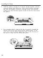
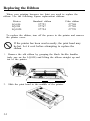
Installing the ribbon
To install the ribbon cartridge, follow these steps:
1. Make sure that the printer is not connected to an electrical outlet.
2. Remove the printer cover.
3. Slide the print head to the middle of the printer.
4. Turn the ribbon-tightening knob in the direction of the arrow to
tighten the ribbon. This step removes excess slack in the ribbon
and makes it easier to install.
1-7
Assembling the Printer
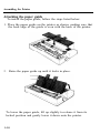
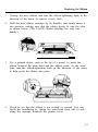
5. Hold the ribbon cartridge by its black, fin-like handles with the
exposed ribbon away from you. (The LQ-850 ribbon cartridge
has only one handle.) Push the cartridge firmly into position,
making sure that the black plastic hooks fit into the slots inside
the printer.
6. Use a pointed object, such as the tip of a pencil, to guide the
ribbon between the print head and the ribbon guide. At the
same time turn the ribbon-tightening knob in the direction of
the arrow to help feed the ribbon into place.
1-8
Assembling the Printer
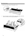
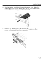
Attaching the paper guide
To install the paper guide, follow the steps listed below:
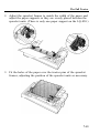
1. Place the paper guide on the printer as shown, making sure that
the back edge of the guide is even with the back of the printer.
2. Raise the paper guide up until it locks in place.
To lower the paper guide, lift up slightly to release it from its
locked position and gently lower it down onto the printer.
1-10
Assembling the Printer
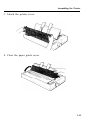
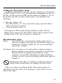
3. Attach the printer cover.
4. Close the paper guide cover.
1-11
Testing the Printer
Now that your printer is fully assembled, you can use the built-in
self test function to see that the printer is working correctly even
though it is not connected to a computer.
You should perform this test to make sure the printer was not
damaged during shipping and to ensure that the ribbon has been
installed correctly.
Before carrying out the test, you need to load a sheet of paper
into the printer.
Before turning on your printer, be absolutely sure you
have removed all protective materials. Turning on the
printer while the print head cannot move may seriously
damage the mechanism.
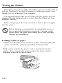
Loading a sheet of paper
1. Make sure that the power switch is turned off. Next, plug the
power cord into a properly grounded electrical outlet.
With certain models, the power cord is not attached to the
printer. If so, connect the power cord to the printer before
plugging it into an electrical outlet.
1-12
Testing the Printer
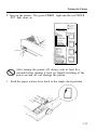
2. Turn on the printer. The green POWER light and the red PAPER
OUT light come on.
After turning the printer off, always wait at least five
seconds before turning it back on. Rapid switching of the
power on and off can damage the printer.
3. Push the paper release lever back to the single sheet position.
1-13
Testing the Printer
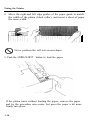
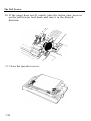
4. Move the right and left edge guides of the paper guide to match
the width of the platen (black roller), and insert a sheet of paper
the same width.
Never perform the self test on envelopes.
8
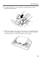
5. Push the LOAD/EJECT button to load the paper.
If the platen turns without loading the paper, remove the paper
and try the procedure once more, but press the paper a bit more
firmly into place.
1-14
Testing the Printer
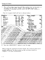
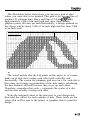
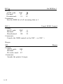
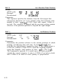
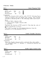
Running the self test
You are now ready to start the printer’s self test. This prints out
the settings of the printer’s DIP switches and the characters in the
printer’s memory. The DIP switch settings are explained later in this
guide. This test can be performed in either of the LQ’s two printing
modes: draft or LQ (Letter Quality). No matter which printing mode
you run the test in, the DIP switch settings are always printed in
draft. The self test is 11 inches wide on the LQ-950 and 14 inches
wide on the LQ-1050. Be sure to use wide paper.
To run the self test in draft mode follow these steps:
1. See that the printer is turned off.
2. While holding down the LINE FEED button, turn on the printer.
After printing starts, release the LINE FEED button.
1-15
Testing the Printer
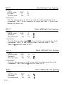
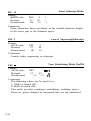
3. The self test does not stop until the printer runs out of paper or
you press the ON LINE button. After checking to see that
everything is operating correctly, press the ON LINE button to
stop the test.
Part of a typical draft self test is shown below:
on
on
0f.f
on off off
off on on
Serial odd
./0123456789:;<=>?
./0123456789:;<=>?@
./0123456789:;<=>?@A
HIJKLMNOPQR
IJKLMNOPQRS
JKLMNOPQRST
/0123456789: ;<=>?OABCDEFGHIJKLMNOPQRSTUVW
4. Press the LOAD/EJECT button to eject the page.
When using the optional cut sheet feeder, the self test print out is
slightly different. See the section on the cut sheet feeder in
Chapter 7 for more information.
1-16
Testing the Printer
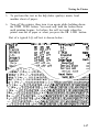
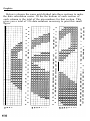
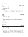
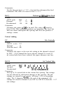
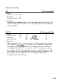
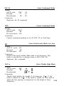
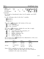
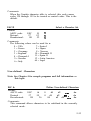
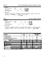
5. To perform this test in the LQ (letter quality) mode, load
another sheet of paper.
6. Turn off the printer, then turn it on again while holding down
the FORM FEED button. You need only hold the button down
until printing begins. As before, the self test ends when the
printer runs out of paper or when you press the ON LINE button.
Part of a typical LQ self test is shown below:
Count t-y
us+l
France
Germany
U.K.
Denmark
Sweden
SWl-1 1-2 1-3
ononon
on
on
on
off
off
on
off
off
on
on
off
on
off
on
off
Page Length
11”
swz0
12"
1”Skip
Invalid
SW;-
Inter-face
Serial even
Serial odd
&'()*t,- ./0123456789:; <=>?@ABCDEFGHIJKLMNOPQRS
‘(I*:+,- ./0123456789:;<=>?@ABCDEFGHIJKLMNOPQRST
(I$+,-* /0123456789:; <=>?@ABCDEFGHIJKLMNOPQRSTU
)*t,-. ,‘0123456789: ;<=>?@ABCDEFGHIJKLMNOPQRSTUV
*t,-. /0123456789: ;<=>?@ABCDEFGHIJKLMNOPQRSTUVW
t,-. /0123456789:; <=>?@ABCDEFGHIJKLMNOPQRSTUVWX
,-./0123456789:;<=>?eABCDEFGHIJKLMNOPQRSTUVWXY
-m/0123456789:; <=>?@ABCDEFGHIJKLMNOPQRSTUVWXYZ
1-17
Connecting the Printer to Your Computer
Your LQ printer has two separate interface connections: a
®
Centronics compatible parallel interface and an RS-232C
compatible serial interface. If you are not sure which one is
required by your computer, check your computer manual for this
information. If you have a suitable shielded cable, you should be
able to connect to most computers immediately.
The printer is set up for parallel data communication at the
factory. If you need to use a serial interface, be sure to adjust the
DIP (Dual In-line Package) switch settings as shown in the section
on DIP switches in Chapter 3.
The few computers requiring other types of interfaces can
probably use one of the optional interfaces described in the section
on interfaces in Chapter 7.
Do not plug more than one interface cable into the printer
at one time. This may damage the printer.
serial interface
1-18
parallel interface
Connecting the Printer to Your Computer
The parallel interface
When connecting your computer to the parallel interface, follow
these steps:
1. Make sure both the printer and your computer are turned off.
2. Plug the cable connector into the printer as shown below. Next
squeeze the wire clips together until they lock onto either side of
the connector.
If your cable has a ground wire, attach this wire to the ground
connector of the printer.
3. Plug the other end of the interface cable into the computer. (If
there is a ground wire at the computer end of the cable, attach
it to the ground connector at the back of the computer.)
1-19
Connecting the Printer to Your Computer
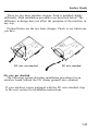
The serial interface
If you are going to use a serial interface, it is best to choose an
Epson serial interface cable. The following is a list of interface
cables and the computers they are designed to work with:
Computer
®
Apple IIc
®
IBM PC and compatibles
Most other computers
Epson cable
#8239
#8297
#8293
When connecting your computer to the serial interface, follow
these steps:
1. Make sure both the printer and your computer are turned off.
2. Connect the interface cable to the serial interface of the printer
as shown
3. Plug the other end of the interface cable into the computer.
Since your printer is set up at the factory to use parallel
communication, you will need to change the DIP switch settings to
select serial communication. Two other serial interface settings,
baud rate and parity, may need to be set before your printer and
computer can communicate properly. See the section on setting DIP
switches in Chapter 3 for more information.
1-20
Using Single Sheets
Reloading during printing
2-2
2-5
Using Continuous Paper
Positioning your continuous
paper supply
2-6
2-11
Switching Between Continuous and
Single Sheets
Switching back to continuous paper
2-12
2-15
Printing on Special Paper
The paper thickness lever
Multi-part forms
Labels
Envelopes
2-16
2-16
2-18
2-18
2-19
Using Single Sheets
Your printer can handle a wide range of paper sizes up to a
maximum width of 10.1 inches on the LQ-850, 13.0 inches on the
LQ-950, or 14.4 inches on the LQ-1050.
Always make sure that your printing is confined to the size of
paper you are using. Avoid printing on the platen (black roller) at
all times.
If you do most of your printing on single sheets, you may find it
more convenient to install the optional cut sheet feeder. This
option automatically inserts a new sheet whenever required and
can hold up to 150 pages. For more details, see Chapter 7.
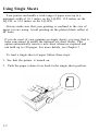
To load a single sheet of paper follow these steps:
1. See that the printer is turned on.
2. Push the paper release lever back to the single sheet position.
2-2
Using Single Sheets
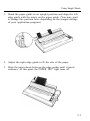
3. Stand the paper guide in an upright position and align the left
edge guide with the arrow on the paper guide. (You may want
to change this position later, depending on the margin settings
of your application program.)
4. Adjust the right edge guide to fit the size of the paper.
5. Slide the paper down between the edge guides until it meets
resistance. At this point, the PAPER OUT light turns off.
2-3
Using Single Sheets
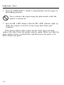
6. Press the LOAD/EJECT button to automatically feed the paper to
the loading position.
Never advance the paper using the platen knob while the
printer is turned on.
7. Press the ON LINE button so that the ON LINE indicator lights up.
When the printer is on line it can accept data from your
computer.
If the platen (black roller) turns but the sheet does not load,
remove the sheet from the printer and try again. Make sure that the
paper release lever is pushed back and then press the paper a bit
more firmly into place.
2-4
Using Single Sheets
Reloading during printing
When you print a document more than one page long using
single-sheet paper, there are two ways your software can *allow you
to load a new sheet at the end of a printed page:
l
If your software sends characters in a continuous stream, the
printer stops printing when it reaches the bottom of the paper.
When this happens, the page ejects and the ON LINE light goes
off automatically.
l
If your software handles printing page by page, it probably
stops sending characters at the end of a page and prompts you
to insert more paper. In this case, the ON LINE light may remain
on. If it does, the first thing you should do is press the ON LINE
button once to take the printer off line.
In either case, once the ON LINE light is off, remove the sheet that
has just been printed and load a new sheet as before. Press ON LINE
to start printing the next page.
2-5
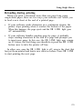
Using Continuous Paper
The tractor built into the LQ is remarkably easy to load and
operate. Its low-profile design takes up little space and can handle a
wide variety of paper widths.
To load continuous paper, follow these steps:
1. See that the printer is turned off.
2. Pull the paper release lever forward to the continuous paper
position.
3. Open the paper guide cover and remove the paper guide.
2-6
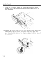
Using Continuous Paper
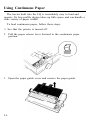
4. Attach the paper rest.
5. Release the sprocket lock levers and slide the left sprocket unit
all the way to the left and lock it in place. Next, slide the right
sprocket unit to roughly match the width of your paper.
2-7
Using Continuous Paper
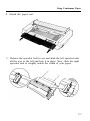
6. Slide the paper support to a point midway between the sprocket
units.
7. Open the sprocket covers.
2-8
Using Continuous Paper
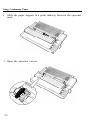
8. Fit the first four holes in the paper over the pins of each
sprocket unit making sure the paper is under the silver edge ; then
close the sprocket covers. Slide the right sprocket unit to a position
where the paper is straight and has no wrinkles; then lock it in place.
Make sure the first sheet of paper has clean, straight edge and
feeds under the silver edge to in sure correct paper feeding.
2-9
Using Continuous Paper
9. Reattach the paper guide as shown below; then slide the edge
guides together so that they meet at about the middle of the
paper’s width.
When using continuous paper, always make sure that the
edge guides are pushed together.
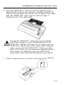
10. Close the paper guide cover and turn on the printer.
11. Press the LOAD/EJECT button to feed the paper to the loading
position. The printer remembers this position and advances each
page to the same position.
12. Press the ON LINE button to set the printer on line so that it can
accept data.
If you find that your word processing or other application
program prints too high or too low on the page or is printing on
the perforations, check the loading position.
If you need to adjust this setting, you can use the microadjustment feature. This feature gives you precise control over the
position of your paper by allowing you to feed the paper either
forward or back in 180th of an inch increments. For more
information see the section on the micro-adjustment feature in
Chapter 3.
2-10
Using Continuous Paper
When using continuous paper, you can also choose the short tear-off
feature to give you added paper-handling capabilities. When this
feature is selected, the printer automatically feeds the paper forward so
that you can tear it off at its perforation. Then, it feeds the paper
backward when data is received so you can resume printing at the
loading position.
This feature makes it easier to detach printed pages and saves the
blank pages that are usually lost between printing jobs. See the
section on short tear off in Chapter 3 for details.
Do not advance the paper using the platen knob while the
1
printer is turned on. If you need to adjust the loading
.
A
position, always use the micro-adjustment feature.
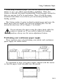
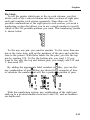
Positioning your continuous paper supply
Three common ways of positioning your printer and continuous
paper supply are shown below.
It’s important to keep your paper supply aligned with the tractor
so that the paper feeds smoothly into the printer.
2-11
f33Etiing Between Continuous and Single
Even with continuous paper loaded in the printer, you can easily
switch to single-sheet printing without removing the continuous
paper from the tractor. To switch from continuous paper to single
sheets, follow the steps below.
1. Open the paper guide cover and press the ON LINE button to set
the printer off line. Then, remove your printed document. If
you are not using the short tear-off function, you need to press
the FORM FEED button to advance your document to a point
where it can be removed.
To avoid feeding your continuous paper backward more
than is necessary, always make sure that you tear off the
printed document before pressing the LOAD/EJECT button.
2-12
Switching Between Continuous and Single Sheets
2. Press the LOAD/EJECT button to feed the continuous paper
backward out of the printer and into a standby position. The
paper is still attached to the tractor, but no longer in the paper
path. The PAPER OUT light comes on when the paper is
completely out of the paper path.
A
1
.
Pressing the LOAD/EJECT button once may not feed the
paper back enough to reach a standby position. If the
PAPER OUT light does not come on, you need to press the
LOAD/EJECT button again. With normal width continuous
paper, you can press the LOAD/EJECT button up to three
times. If, however, you are using narrow paper (between 4
and 6 inches) you should only press the LOAD/EJECT
button once. Also, do not use this button to eject labels.
3. Push the paper release lever back to the single sheet position.
2-13
Switching Between Continuous and Single Sheets
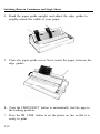
4. Stand the paper guide upright, and adjust the edge guides to
roughly match the width of your paper.
5. Close the paper guide cover. Next, insert the paper between the
edge guides.
6. Press the LOAD/EJECT button to automatically feed the page to
the loading position.
7. Press the ON LINE button to set the printer on line so that it is
ready to print.
2-14
Switching Between Continuous and Single Sheets
Switching back to continuous paper
To switch back to printing with continuous paper, first see that
the single sheet has ejected.
1. Open the sheet guide cover. Next, lower the paper guide onto
the back of the printer and slide the edge guides together so that
they meet at about the middle of the paper’s width.
2. Pull the paper release lever toward you.
3. Press the LOAD/EJECT button to feed the paper to the loading
position.
4.
Press the ON LINE button to set the printer on line so that it can
accept data.
2-15
Printing on Special Paper
In addition to using single sheets and continuous paper, your
printer can also print on a wide variety of paper types, including
multi-part forms and labels. You can even feed envelopes manually or
with the optional cut sheet feeder. Before printing on these special
types of paper you need to adjust the paper thickness setting. Never
use reverse feed with labels.
The paper thickness lever
To accommodate various thicknesses of paper, the LQ printer is
equipped with a paper thickness lever that can be set to one of eight
positions. These positions are identified by a scale on the printer
frame next to the lever. For normal use, the lever should always be
set to position 2 on the scale.
Before changing the paper thickness setting, first make sure the
power is off and then open the printer cover.
If you’ve been using the printer just before opening the
printer cover, be careful not to touch the print head
because it may be hot.
2-16
Printing on Special Paper
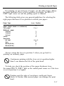
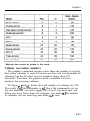
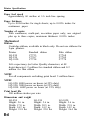
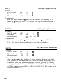
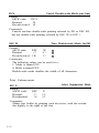
For printing on special types of paper, see the table below. When
the paper thickness lever is set to position 4 or higher, the MULTIPART light comes on and the printing speed is reduced.
The following table gives you general guidelines for selecting the
right paper thickness lever position to match your paper:
Paper Type
Paper (single sheets or continuous)
Thin paper
Multi-part paper
2-sheet
3-sheet
4-sheet
Labels
Envelopes
Air mail
Plain
Bond (20 lb.)
Bond (24 lb.)
Lever Position
2
2 or 1
3
4
5
4
4 or 5
6
6
7
Always return the lever to position 2 when you go back to
printing on ordinary paper.
Continuous printing with the lever set at a position higher
8 than 2 can shorten the life of the print head.
To help you check the position of the paper thickness lever,
the orange MULTI-PART light on the control panel comes on if the lever
is set to position 4 or higher.
Printing past the edge of envelopes, multi-part forms,
labels, or thicker than normal paper can damage the print
head.
2-17
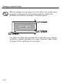
Printing on Special Paper
When you print on anything thicker than normal paper, such as
envelopes or multi-part forms, be absolutely sure that your printing
stays within the printable area of the paper. See pages 2-20 and 8-3
for more about printable area.
Multi-part forms
Your printer can also use continuous multi-part forms. These
multiple forms should have no more than four parts including the
original.
Multi-part forms should not be used with the single-sheet feeding
system or the cut sheet feeder.
You load continuous multi-part paper the same way that you
load continuous paper. See the section on loading continuous paper
in this chapter for details. The only difference is that you need to
adjust the paper thickness lever to suit the thickness of your paper
before loading. When you set the paper thickness lever to position 4
or above, the MULTI-PART light comes on and the printing speed is
reduced. See the table on the previous page for the correct paper
thickness setting.
Labels
If you need to print labels, always choose the type mounted on a
continuous base sheet provided with sprocket holes for use with the
tractor. If you attempt to print labels using the single-sheet feeding
system, labels on a shiny base sheet almost always slip a little.
You load labels the same way that you load continuous paper.
See the section on loading continuous paper in this chapter for
details. The only difference is that you need to adjust the paper
thickness lever to match the thickness of your labels. See the table
on page 2-17 for the correct paper thickness setting.
To remove labels, tear off at a perforation behind the push
tractor. Then, set the printer off line and use the FORM FEED button
to eject the labels.
2-18
Printing on Special Paper
Never feed the labels backward through the printer.
Labels can easily come off the backing and jam the
8 printer. Also, never use the LOAD/EJECT button to eject
labels or to feed labels backward to the standby position.
If a label does become stuck in the printer mechanism,
refer the problem to your dealer. Since labels are
especially sensitive to temperature and humidity, always
use them under normal operating conditions.
Envelopes
With the optional cut sheet feeder installed, you can print on a
variety of envelopes, including air mail, plain, or bond. See the
section on the cut sheet feeder in Chapter 7. Before loading
envelopes into the cut sheet feeder, you need to adjust the paper
thickness lever. See the table showing envelope types and
recommended lever positions on page 2-17.
You can also feed envelopes individually, using the single sheet
loading feature. First, set the paper-thickness lever as indicated in
the table on page 2-17. Then, follow the single sheet loading
instructions at the beginning of this chapter. Because of the
thickness of envelopes, however, you may have to press down
slightly on the envelope at the same time you press the LOAD/EJECT
button.
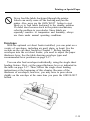
2-19
Printing on Special Paper
When printing on envelopes, be sure that your application
program settings keep the printing entirely within the
printable area of the envelopes as shown below.
0.33 n or more
3-
J k0.12” or more
i
- 0.87” or more
t
To make sure that the printing fits within this area, always
perform a sample printing test using a normal single sheet
of paper before printing on envelopes.
2-20
Operating the Control Panel
Lights
Buttons
SelecType
Other control panel features
3-2
3-2
3-3
3-4
3-5
Setting the DIP Switches
3-6
Page Length
3-9
Skip Over Perforation
3-10
Adjusting the Loading Position
The loading position
Micro adjustment
3-12
3-12
3-12
Short Tear Off
3-14
Selecting Typestyles
Character fonts
Character pitch
Condensed mode
If SelecType does not work
3-16
3-16
3-16
3-16
3-19
3-20
Selecting Character Sets
Choosing an international character set 3-20
3-20
Choosing a character table
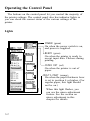
Operating the Control Panel
The buttons on the control panel let you control the majority of
the printer settings. The control panel also has indicator lights so
you can check the current status of the various settings of the
printer.
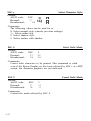
Lights
cm POWER l2El READY &Zl MUL-I PART
63 PAPER OUT
- POWER (green)
On when the power switch is on,
and power is supplied.
SelecType
FONT
READY (green)
On when the printer is ready to
accept input data. Flickers during
printing.
1 ON LINE
0 ORAFT
0 ROMAN
~0 SANS SERIF
El
FORM FEED
!
L3
PAPER OUT (red)
On when the printer is out of
paper.
LINE FEED
L
a
i
LOAD/EJECT
&
-MULTI-PART (orange)
On when the paper thickness lever
is set to position 4 or higher. (For
regular paper, this light should
not be on.)
Iti
When this light flashes, you
can use the micro-adjustment
feature. See the section on
micro adjustment in this
chapter for details.
3-2
Operating the Control Panel
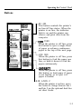
Buttons
0 POWER
0 READY
0 MULTI.PART
3 PAPER OUT
SelecType
-
0 SANS SERIF
0 SLOT A
0 SLOT B
0 1s CPI
---I
0 CONDENSE0
II-.
FORM FEED-
ON LINE
This button controls the printer’s
on line/off line status. When the
printer is on line, the indicator
light is on and the printer can
receive and print data from the
computer.
J-FORM FEED
When the printer is off line, press
this button to eject a single sheet
of paper or advance continuous
paper to the top of the next page.
-L LINE FEED
When the printer is off line, press
this button to feed the paper one
line, or hold it down to feed the
paper continuously.
l- LOAD/W ECT
When the printer is off line, press
this button to load paper if paper
is not loaded, or to eject it if
paper is loaded.
-BIN 1/BIN 2
When the printer is on line, press
this button to change between bin 1
and bin 2 on the optional dual bin
cut sheet feeder.
3-3
Operating the Control Panel
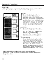
SelecType
The settings you select using the SelecType panel remain valid
even after you turn off, reset, or initialize the printer.
0 POWER
0 READY
0 MULTI-PART
0 PAPER OUT
S&c Type
FORM FEED
- FONT
Press this button to select a
character font. The orange
indicator lights show which font
has been selected. If optional font
modules have been installed, these
fonts can be selected by choosing
either SLOT A or SLOT B. See the
section on selecting fonts in this
chapter for further information.
1 PITCH
Press this button to select the
character pitch. You can choose
10, 12, or 15 CPI (character per
inch) or PS (proportional
spacing). The orange indicator
light shows the selected pitch.
-L CONDENSED
Press this button to select either
condensed or normal printing.
The orange light is on when the
printer is in condensed mode. In
this mode, all characters are
printed at approximately 60% of
their normal width. This mode
cannot be combined with 15 CPI.
Two combinations do not work: draft proportional and
condensed 15 cpi. If you try to choose one of these, the printer
beeps three times.
3-4
Operating the Control Panel
Other control panel features
The control panel of the LQ also gives you access to several
special functions.
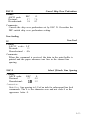
Self test
By holding down the FORM FEED or LINE FEED button while you
turn on the printer, you can start the LQ’s self test. This prints out
the DIP switch settings and the characters in the printer’s ROM
(Read Only Memory). See the section on the self test in Chapter 1
for further information.
Micro adjustment
By pressing the FORM FEED and LINE FEED buttons immediately after
loading paper and when the printer is on line and the orange indicator
light is flashing, you can move the paper 1/180th of an inch at a time
for fine adjustments to the loading and short tear-off positions. See the
section on micro adjustment in this chapter for further information.
Data dump
By holding down both the LINE FEED and FORM FEED buttons
while you turn on the printer, you turn on the data dump mode.
This feature allows advanced users to diagnose many problems. See
the section on the data dump mode in Chapter 6 for further
information.
3-5
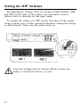
Setting the DIP Switches
By adjusting the settings of the two groups of DIP switches (SW1
and SW2) in the back of the printer, you can control various
features such as character set and page length.
To change the setting of a DIP switch, first turn off the printer.
Using a pencil, pen, or other pointed instrument, change the setting
as shown below. Then, turn the printer back on.
Your new settings will not become effective unless the
printer is turned off and on, or reset.
3-6
Setting
DIP Switches
the
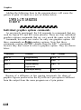
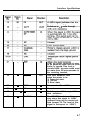
The tables below describe the functions of the DIP switches.
DIP Switch 1
Switch
Description
OFF
ON
1-1
1-2
International character set
See the table below.
1-3
I
1-4
Character table
1-5
Print direction for graphics
1-6
1 Not used
Graphics
Italics
Unidir.
Bidir.
I
I
I
1-7
Cut sheet feeder mode
Valid
Invalid
1-8
6 Kbytes receive buffer
0 bytes
6 Kbytes
DIP Switch 2
Switch
Description
ON
OFF
12 inches
11 inches
ON
OFF
2-1
Page length
2-2
Skip over perforation
2-3
Interface/Parity
See the table below.
Baud rate
See the table below.
2-4
2-5
2-6
2-7
Short tear-off mode
ON
OFF
2-8
Auto line feed
ON
OFF
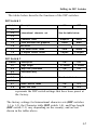
represents the DIP switch settings that have been preset at
the factory.
The factory settings for International character sets (DIP switches
1-1 to 1-3), the Character table (DIP switch 1-4), and Page length
(DIP switch 2-1) vary depending on the country, and are not
shown in the tables above.
3-7
Setting the DIP Switches
International character set selection
1-1
1-2
Country
U.S.A.
France
::
OFF
OFF
:i
OFF
OFF
I
-_-^
_
EeLmany
D&mark 1
Sweden
Italy
Spain 1
* See page 3-20 for other character sets.
Interface/parity selection
Baud rate selection
pgyz$=j
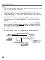
Print direction for graphics
With unidirectional printing, the print head prints in one direction
only to eliminate any possible deviation in the dot positions, making it
ideal for printing graphics such as lines or boxes. When DIP switch
1-5 is ON, unidirectional is valid; when it is OFF, bidirectional is
valid. Either one can be overridden by a software command.
Auto Line Feed
When auto line feed is ON (DIP switch 2-8 ON), each carriage
return code (CR) is automatically accompanied by the line feed code
(LF).
3-8
Page Length
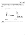
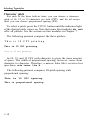
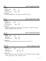
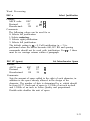
By setting DIP switch 2-1, you can select a page length of 11 or
12 inches. By turning the switch on, you set the page length at 12
inches. When you turn the switch off, you set the page length at 11
inches.
To change the setting of a DIP switch, first turn off the printer.
Next, change the DIP switch; then turn the printer back on.
o/
01
01
I
0,
01‘/-
01
01
1 l-inch paper
0%
I la-inch
;;I
/
,’ /
2-1 OFF
paper
01
/
/I
2-1 ON
Your new settings will not become effective unless the
printer is turned off and on, or reset.
3-9
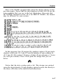
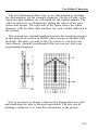
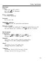
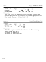
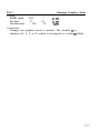
Skip Over Perforation
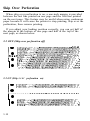
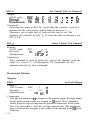
When skip over perforation is on, a one-inch margin is provided
between the last line printed on one page and the first line printed
on the next page. This feature may be useful when using continuous
paper because it will cause the printer to stop printing, skip over the
perforation, then resume printing.
If you adjust your loading position correctly, you can get half of
the margin at the bottom of one page and half at the top of the
next page, as shown below.
2-2 OFF (Skip over perforation off)
. LC,““YYL “I~~” ..LIL.‘.“I ya-u* v . *I‘-*- L
“*I”I”“I”“.).--r
0
123456789 :;<=>?@ABCDEFGHIJKLMNOPQRSTUVWXYZ[\
23456789:;<=>?@ABCDEFGHIJKLMNOPQRSTUVWXYZ[\]
3456789:;<=>?@ABCDEFGHIJKLMNOPQRSTUVWXYZf\l~
0
___- 456789:;<=>?@ABCDEFGHIJKLMNOPQRSTUVWXYZ[\l*_____ ------ -- _--- - ---- -----------56789:;<=>?@ABCDEFGHIJKLMNOPQRSTUVWXYZ[\]A-'
6789:;<=>?@ABCDEFGHIJKLMNOPQRSTUVWXYZ[\I--'a
l 789 :;<=>?@ABCDEFGHIJKLMNOPQRSTUVWXYZ[\l^_'at
89:;<=>?@ABCDEFGHIJKLMNOPQRSTUVWXYZ[\I^_'abc
l 9:; <=>?@ABCDEFGHIJKLMNOPQRSTUVWXYZ[\l^_'abcd
:;<=>?@ABCDEFGHIJKLMNOPQRSTUVWXYZ[\]*-'abcde
I
I
2-2 ON (Skip over perforation on)
l
Il
23456789:;<=>?@ABCDEFGHIJKLMNOPQRSTUVWXYZ[\]'
3456789:;<=>?@ABCDEFGHIJKLMNOPQRSTUVWXYZ[\lA-
I
t----------- -------_ --------------
I 0
l
3-10
456789:;<=>?@ABCDEFGHIJKLMNOPQRSTUVWXYZ[\]-56789:;<=>?@ABCDEFGHIJKLMNOPQRSTUVWXYZ[\]*-'z
6789: ; <=>?@ABCDEFGHIJKLMNOPQRSTUVWXYZ[\]~wrat
Skip Over Perforation
Most application programs take care of the top and
1
bottom margins. Therefore, do not turn skip over
A perforation
on unless your program does not provide these
l
margins.
3-11
Adjusting the Loading Position
The loading position
The loading position is the position of the paper when it has been
automatically loaded by the printer.
The loading position is important because it determines where the
printing begins on the page. If the printing is too high or too low
on the page, change the loading position using the micro-adjustment
feature described below.
Never use the platen knob for paper feeding except in case
of a paper jam or other paper feeding problem. If you
need to adjust the loading position, always use the microadjustment feature.
Until this loading position is reset, the printer remembers this
loading position and uses it as a reference point for feeding the
paper.
Micro adjustment
The micro-adjustment feature moves the paper 1/180th of an inch
at a time to make fine adjustments to the loading or short tear-off
positions. Once you have used micro adjustment to change the
loading position of continuous paper, the printer remembers that
position even after it is turned off.
However, when you use micro adjustment to change the loading
position of single sheet paper, the printer does not remember this
position after the power is turned off. When the power is turned
back on, the loading position returns to its factory setting.
This section describes using micro adjustment to change the
loading position, but you can adjust the short tear-off position
the same way. See the short tear-off section in this chapter for
more information.
3-12
Adjusting the Loading Position
To perform micro adjustment of the loading position, first load
your paper, and then press the ON LINE button to set the printer on
line. The MULTI-PART indicator light starts to flash. While this light
is flashing, you can use the FORM FEED and LINE FEED buttons for
micro adjustments.
Now press the FORM FEED button to feed the paper forward or
the LINE FEED button to feed the paper backward.
Each time you press the button, the paper moves 1/180 of an
inch. If you hold the button down, the paper moves continuously in
1/180 of an inch increments.
When the paper reaches the factory set loading position, the
printer beeps and micro-adjustment feeding pauses for a moment
before continuing. You can use this factory setting as a reference
point when adjusting the printer’s loading position.
Micro adjustment can be used to adjust the loading position
1
after loading paper only. Using micro
.
A immediately
adjustment on continuous paper establishes a new loading
position that remains valid even after the printer is turned
off, reset, or initialized. When using micro adjustment on
single sheet paper, the new loading position does not remain
valid after the printer is turned off or reset. When the paper
reaches either the minimum or maximum top margin, the
printer beeps and the paper stops moving.
3-13
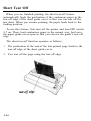
Short Tear Off
When you are finished printing, the short tear-off feature
automatically feeds the perforation of the continuous paper to the
tear-off edge of the sheet guide cover so that you can tear off the
last sheet. When you resume printing, the paper feeds back to the
loading position.
To use this feature, first turn off the printer and turn DIP switch
2-7 on. Then, load continuous paper in the normal way, but leave
the paper guide cover open so that you can use the guide’s tear-off
edge.
The short tear-off function operates as follows:
1. The perforation at the end of the last printed page feeds to the
tear-off edge of the sheet guide cover.
2. You tear off the page using the tear-off edge.
3-14
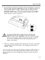
Short Tear Off
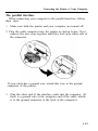
3. If you need to adjust the position of the perforation to meet the
tear-off edge, use micro adjustment. First, see that the printer is
on line and the MULTI-PART indicator light is flashing. Then,
adjust the position in 1/180 of an inch increments by pressing
the FORM FEED button to feed the paper forward or the LINE
FEED button to feed it backward.
Use micro adjustment to adjust the tear-off position
immediately after the operation of the short tear-off
function. After micro adjustment, the new tear-off position
is reset and remains valid even after the printer is turned
off, reset, or initialized. Never use the short tear off
feature with labels.
4. When you resume printing after tearing off the sheet, the paper
automatically feeds backward to the loading position before
printing begins.
You can leave the short tear-off feature turned on (DIP switch 2-7
on) even when you are using single sheets. When you move the
paper release lever to the single sheet position, short tear-off is
disabled.
3-15
Selecting Typestyles
Your printer can produce a wide range of typestyles by
combining different fonts, pitches, widths, and other enhancements.
You can select the typestyles in two different ways: by using
software commands, and by pressing SelecType buttons on the
control panel.
The settings you select using the SelecType panel remain valid
even after the printer is turned off, reset, or initialized. However,
commands from your software application program temporarily
override the SelecType setting.
This chapter describes only the features controlled by SelecType.
To use software commands, see the instructions for your application
program or Chapter 9, Command Summary.
You can use the SelecType section of the control panel to choose
fonts, pitches, and condensed printing. Orange lights indicate which
features you have chosen.
Character fonts
To select a font, press the FONT button until the font’s orange
indicator light comes on. Note that font selection skips over SLOT A
or SLOT B if no optional font module is installed in that slot.
The character sets of the three built-in fonts are shown below. To
expand your range of typestyles, you can use four optional font
modules. For details on their installation and use, see the section on
font modules in Chapter 7.
3-16
Selecting Typestyles
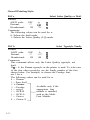
Draft mode uses fewer dots per character for high-speed printing.
DRAFT
We’ve just seen your excellent a d for
zebras in a recent back issue of
T..ca.d.s..r . ..~...s T.i..me.s - W h a t i s t h e p r i c e s c h e d u l e
for quantities over one g r o s s ?
miniature
The Roman and Sans Serif Letter Quality (LQ) fonts use a larger
number of dots for higher print quality at a lower speed.
ROMAN
.
'"#$%&'()*+,-./0123456789:;<=>?@ABCDEFGHIJK
LMNOPQRSTUVWXYZ[\]^-‘abcdefghijklmnopqrstuv
e . . . a. *.
We’ve just seen your excellent ad for
miniature zebras in a recent back issue of
Trader’s Times. What is the price schedule
for quantities over one gross?
SANS SERIF
!“#$%&‘()*+,-. /0123456789:;<=>?@ABCDEFGHIJK
LMNOPQRSTUVWXYZ[\]---’ abcdefghijklmnopqrstuv
wxyz{l}“CU~BBBB~g~~~~~AA~~~8~6~~~~~~~~~~~~6
CJflRBQ&r~+*i<B
We’ve just seen your excellent ad for
miniature zebras in a recent back issue of
Trader’s Times. What is the price schedule
for quantities over one gross?
3-17
Selecting Typestyles
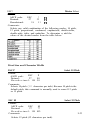
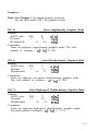
Character pitch
For each of the three built-in fonts, you can choose a character
pitch of 10, 12, or 15 characters per inch (CPI), and for all except
draft you can choose proportional spacing (PS).
To select a pitch, press the PITCH button until the indicator light
of the desired pitch comes on. Note that some font modules do not
offer all pitches. See the section on font modules in Chapter 7.
The following printout compares the three pitches:
This is 10 CPI printing.
This is 12 CPI printing.
This is 15 CPI printing.
In 10, 12, and 15 CPI, each character is given the same amount
of space. The width of proportional spacing, however, varies from
character to character. Therefore, a narrow letter like i receives less
space than a wide letter like W.
The following printout compares IO-pitch spacing with
proportional spacing:
This is 10 CPI spacing.
This is proportional spacing.
3-18
Selecting Typestyles
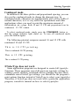
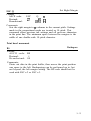
Condensed mode
In addition to the three pitches and proportional spacing, you can
also use the condensed mode to change the character size. In
condensed mode, characters are approximately 60% of the width of
normal characters; so it is very useful for spreadsheets and other
applications where you need to print the maximum amount of
information on a page. Both 10 and 12 CPI and proportional can be
condensed; 15 CPI cannot.
To select condensed mode, simply press the CONDENSED button so
that the orange indicator light comes on. To turn off condensed mode,
press the button again.
The following printout compares normal 10 and 12 CPI with
condensed 10 and 12 CPI.
This is 10 CPI printing.
This is condensed 10 CPI printing,
This is 12 CPI printing.
This is condensed 12 CPI printing,
If SelecType does not work
Some application programs are designed to control all typestyle
functions. These programs cancel all previous typestyle settings by
sending certain software commands before printing. Because these
commands cancel SelecType settings, you should use the program’s
print options function instead of SelecType to select your typestyles.
Therefore, if SelecType does not work with a particular application
program, consult its manual on how to select typestyles.
3-19
Selecting Character Sets
By changing the setting of the DIP switches, you can select one of
eight international character sets and one of two character tables.
Once you have set the DIP switches for a certain character set, that
set is the default character set; it remains valid even after the printer
is turned off, reset, or intialized. Software commands however,
override DIP switch settings until they are cancelled or the printer is
turned off, reset, or intialized.
To change the setting of a DIP switch, first turn off the printer.
Set the DIP switch, and then turn the printer back on.
Choosing a character set
Selection of a character set provides you with the characters used
in other languages or with legal symbols. To obtain the desired
character set, set switches l-l, 1-2, and l-3 according to the DIP
switch table on page 3-8.
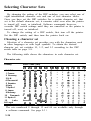
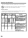
The following table shows the characters in each character set.
Character sets
Country
0 U.S.A.
1 France
2 Germany
3 U.K.
4 Denmark I
5 Sweden
6 Italy
7 Spain I
8 Japan
9 Norway
10
Denmark
11 Spain II
12
Latin
64 Legal
ASCII code (hex)
23
24
40
58
5C
#
#
#
f
#
#
#
$
$
$
$
$
tl
$
@
ii
5
@
@
B
@
E
o
x
[
B
is
o
\
G
u
\
0
0
\
# $
#
$
America
It
$
II
50
5E
60
78
7C
7D
7E
IE
0
;
R
# $ & i fi
3
o
’
B
6
The sets numbered 8 through 12 and 64 are available only through
a software command. See page 9-3 1.
3-20
setting ChalWAer sets
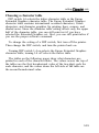
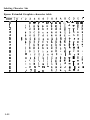
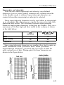
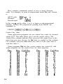
Choosing a character table
DIP switch l-4 selects the italics character table or the Epson
Extended Graphics character table. The Epson Extended Graphics
character table contains international accented characters, Greek
characters, and character graphics for printing lines, corners, and
shaded areas. Since the character table setting affects only the upper
half of the character table, you can still print text if you have
selected the Extended Graphics set. Also, you can still print italics if
you use the proper software command.
To change the setting of a DIP switch, first turn off the printer.
Then change the DIP switch, and turn the printer back on.
Turning DIP switch 1-4 on selects the Epson Extended Graphics
character table; turning l-4 off selects the italics table.
The tables on the following pages show what characters are
printed in each of the character tables. The values across the top of
the tables are the first hexadecimal value of the two-digit code for
each character, and the values down the left side of the table are
the second hexadecimal value.
3-21
Selecting Character Sets
Epson Extended Graphics character table
CODE10123456789A8~DEF
0
1
2
3
4
5
6
7
8
9
0 e P t p (; & 6 : .A.:I:’ L 4. a P
!lAQaqi.icei$$L~bf
“2BRj-,r~fi6@$j~r~
A
#3CScsQ~B~pns
84DTdtiiSAt-LCr
B%5EUeu21bfiI(traJ
&6FVfvifia-itrP+
'7GWgw~iiQlttt~
(8HXhx6$ilhf@’
)91YiyBUr4cJB*
* :JZjzbuT[*rQ.
8
C
+ ; K[ktY@&l~g6d
,<L\l:
D
-=M]lll}iYiJ’)p12
ietJ),a-
E
F
3-22
;
>
N
A
n
?
0
_
0
*
Xp~aJt)eD
Etf~~+mn
selecting Character sets
Italics character table
CODE10123456789ABCDEF
0
1
2
3
4
5
6
7
8
9
A
6
C
D
E
F
08P’p
!lAQaq
” 2 B R b r
0 e P t p
!lAQaq
1, 2 B R b r
#3CScs
$4DTdt
%5EUeu
&GFVfv
'7GWgw
(8HXhx
)SIYiy
* : J Z j z
$4DTdt
XdEUeu
&GFVfv
‘7GWgw
(8HXhx
)SIYiy
* : JZjs
+ ; K [ k {
, < L \ 1 ;
-=M]m}
> N A n *
; ? 0 _ 0
+ ; KC&{
,CL\ll
-=MlS]
>N^n*
;?o-o
XbCScs
3-23
Selecting Character Sets
3-24
Software
Choosing from a menu
A quick test
Computer-printer communications
Word processors
Spreadsheets
Graphics programs
4-2
4-2
4-3
4-3
4-4
4-6
4-7
Graphics
The print head
The graphics command
Column reservation numbers
A simple graphics program
Using hand-calculated data to
print graphics
Individual graphics options commands
The reassigning command
4-8
4-9
4-12
4-13
4-14
User-Defined Characters
Designing your characters
Sending information to the LQ
Printing user-defined characters
Copying ROM characters to RAM
Letter Quality characters
4-20
4-20
4-24
4-27
4-27
4-28
4-14
4-18
4-19
Software
Now that you have set up and tested the LQ, you should make
sure that it works with the application programs you want to use.
Most application programs let you specify the type of printer you
are using so that the program can take full advantage of the
printer’s features. Many of these programs provide an installation
or setup section that presents a list of printers from which to
choose.
Choosing from a menu
Because the family of Epson printers shares a great many
commands, you can use an application program even if it does not
list the LQ-850, LQ-950, or LQ-1050 on its printer selection menu.
Choose from the following list:
LQ-850/950/1050
LQ-2500
LQ-800/1000
LQ- 1500
If none of these printers is listed, select the first one available on
the following list.
EX
FX
LX
E&
Epson printer
Standard printer
Draft printer
To use all the features of the LQ-850, LQ-950, and LQ-1050,
however, it is best to use a program with the LQ-850, LQ-950, or
LQ-1050 on its menu. If your program does not list these printers,
contact the manufacturer to see if an update is available.
4-2
Software
A quick test
After you set up your application program for your printer by
following the instructions in the application program manual and
the instructions above, print a sample document to make sure that
the program and the printer are communicating properly. If the
document does not print the way you think it should, re-check the
program’s printer selection and installation routine. If you are still
having trouble printing, consult Chapter 6.
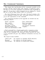
Computer-printer communications
Computers and printers communicate by using numerical codes to
represent characters and commands. To be sure that the two devices
translate the characters in the same way, a standard code has been
developed-the ASCII (American Standard Code for Information
Interchange). Many application programs specifically ask for ASCII
codes to send printer commands.
The ASCII standard includes codes for printable characters
(letters, punctuation marks, numerals, and mathematical symbols)
and 33 other codes called control codes. The control codes are for
such functions as sounding the beeper and performing carriage
returns. Because the 33 control codes are not enough to control all
possible printer functions, most printer commands are actually a
sequence of two or more codes.
One of the 33 control codes, the escape code, signals the
beginning of a sequence of codes. Therefore, most printer
commands are sequences of codes, the first of which is the escape
code. This manual uses the ASCII abbreviation ESC for this code.
When using control codes to select printer functions for an
application program or programming language, check the manual
for the program or language to find the appropriate method of
inserting the code into the program. Further details on the methods
to use are in the rest of this chapter.
4-3
Software
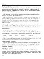
Naming and using commands
In order to use printer commands, you should know how they are
recognized by your software program. The most common way of
naming codes or commands is with one of two numbering systems,
decimal or hexadecimal.
The decimal system is the standard numbering system based on
units of ten, using the numerals 0-9.
The hexadecimal, or hex, system is based on units of 16, and is
often used by programmers. Instead of using only the numerals 0
through 9, the hex system also uses the letters A through F. For
example, the decimal numbers 9, 10, 11, and 12 are 09, 0A, 0B,
and 0C in hex.
Since the most frequently used hexadecimal numbers are between
0 and FF hex (0 to 255 in decimal), it’s common to write
hexadecimal numbers that are less than 16 with a zero in front, as
shown above.
In this book, hex numbers are distinguished from decimal
numbers by the word hex after them (for example, 1B hex). Other
common ways of denoting a hexadecimal number are the following:
IBH
$1B
&1B
&H1B
<1B>H
The Command Summary and the Quick Reference Card give both
the decimal and hex numbers for each command.
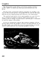
Unidirectional printing
The LQ printers have the advanced capability of printing text and
graphics bidirectionally. For exact alignment of some graphic images
you may want to select unidirectional printing. See ESC U in the
command summary.
Word processors
In many ways, word processors demand the most from your
printer. When you create and print a document, you may use many
print styles and fonts, reformat pages, add headers and footers, and
use bold, italic, and other effects.
4-4
Software
Once you have installed your word processor by using the lists on
page 4-2, you can ordinarily use a fixed set of printer features by
using a word processor command to place markers around the text
to be altered. When the document is printed, the markers are
recognized and translated into suitable commands for your printer.
On your screen, some programs show the markers in a distinctive
way, while others display the text as it will appear-for example, in
bold or italics.
This method is normally restricted to features that can be found
on almost all printers, such as bold and underlining.
Some programs also provide a way of placing complete printer
commands in the text. These commands may or may not be visible
on your screen. This method has the advantage of allowing you to
use any printer command, not just a limited set. To make use of it,
however, you need to understand how to use the printer’s
commands.
Check the manual for your word processor to see if you can
place printer commands in your text. If this is possible, use the
Command Summary in this manual to find the command, and use
the manual for your word processor to find how to assign the
command.
If your LQ is not printing correctly, check both the LQ and your
word processor and review this checklist:
0 Make sure you’ve selected the correct printer.
0 Carefully read the printer setup and installation information in
your word processor’s manual.
0 Check the printer options that may be part of the installation or
setup section (line feeds, interface).
0 Make sure your word processor is capable of sending the proper
commands to your printer.
0 If you’re still having difficulty printing, check the
troubleshooting section in your word processor’s manual and
Chapter 6 of this manual.
Spreadsheets
Although spreadsheets seldom use as many printing styles as word
processors, they do have some very specific requirements.
Installation and column width
If your spreadsheet program provides a list of printers, use the
list on page 4-2 to find the proper selection. If your spreadsheet
doesn’t have a printer setup routine, carefully read the program’s
manual for information on printing.
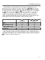
A major concern for printing spreadsheets is the width of the
printer. The LQ-850 is an 80 column printer, the LQ-950 is a 110
column printer, and the LQ-1050 is a 136 column printer, but by
using condensed 12 cpi you can print up to 160 columns on the
LQ-850, 220 columns on the LQ-950, and 272 on the LQ-1050.
Therefore, if your spreadsheet asks the number of columns your
printer can print, you can specify up to 160, 220, or 272.
Printer commands
Unlike word processors, spreadsheet programs don’t usually let
you change printer commands within a spreadsheet. Instead, one
style or mode of printing is used for the whole spreadsheet. With
the LQ, there are two main ways of sending commands to control
the printing of a spreadsheet.
First, almost all spreadsheets have the capability of sending
commands to a printer. Look in the manual for your spreadsheet to
find out how to send printer commands. Then look in the
Command Summary in this manual to find the proper codes to
send.
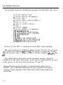
For example, your spreadsheet might use a “setup string” to send
printer commands. To prepare a setup string for condensed 12 cpi,
you would look up the proper command in the Command
Summary.
Software
The command for 12 cpi is ESC M, and the command for
condensed is SI. Because most spreadsheets use the decimal
equivalent for the commands, (also given in the Command
Summary), a setup string for condensed 12 cpi might look like this:
/027/077/015
The number 027 is for the escape code, 077 is for M, and 015 is for
SI (condensed).
The second method is SelecType, a feature described in Chapter 3.
This feature allows you to choose print styles with buttons on the
control panel.
If your spreadsheet is not printing correctly, check both the LQ
and your spreadsheet program and review this checklist:
0 If the program asks you to select a printer, be sure you have
selected the correct one.
q
If you’re using the program’s print facility, recheck the LQ’s
Command Summary to make sure you’re sending the correct
commands.
0 If you’re still having difficulty printing, check the
troubleshooting section in your spreadsheet program’s manual or
Chapter 6 of this manual.
Graphics programs
The LQ is capable of producing finely detailed graphic images. A
later section of this chapter gives specific information on the
graphics commands, but the easiest way to take advantage of the
LQ’s capabilities is with one of the many graphics programs
available.
When buying graphics software, always make sure it has a
suitable option to allow printouts on an LQ printer. Any program
with an option for an LQ printer should give excellent results.
Most graphics programs have a printer selection procedure. Check
the lists on page 4-2 to find the proper selection.
4-7
Graphics
The dot graphics mode allows your LQ to produce pictures,
graphs, charts, or almost any other pictorial material you can
devise.
Because many commercial software programs use graphics, you
may be able to print pictures and graphs like the ones on this page
and the next by simply giving your software a few instructions.
The quickest and easiest way to print graphics on your LQ is to
use a commercial graphics program. With such programs you
usually create an image on your monitor and then give a command
to send the image to the printer.
If you use commercial software that produces graphics, all you
need to know about dot graphics is how to use the software. If, on
the other hand, you wish to do your own programming or merely
wish to understand how the LQ prints graphics, read on.
Graphics
I ncome Breakdown
Marketing and
Advertising
\ Profit
Salaries and
Production
-
Development
The print head
To understand dot graphics you need to know a little about how
the LQ’s print head works.
The LQ’s print head has 24 pins. As it moves across the page,
electrical impulses cause the pins to fire. Each time a pin fires, it
strikes the inked ribbon and presses it against the paper to produce
a small dot. As the head moves across the paper, the pins fire time
after time in different patterns to produce letters, numbers, or
symbols.
Because the dots overlap each other both horizontally and
vertically in the Letter Quality mode, it is difficult to see individual
dots. Instead, the letters and symbols seem to be made of unbroken
lines.
In order for the dots to overlap vertically, the pins in the print
head are in more than one column, but the intelligence of the
printer handles the timing of pin firings so that the effect is that of
24 pins arranged in a single vertical column.
4-9
Graphics
Dot patterns
The LQ’s print head is able to print graphics as well as text
because graphic images are formed on the LQ about the same way
that pictures in newspapers and magazines are printed. If you look
closely at a newspaper photograph, you can see that it is made up
of many small dots. The LQ also forms its images with patterns of
dots, as many as 360 dot positions per inch horizontally and 180
dots vertically. The images printed by the LQ can, therefore, be as
finely detailed as the ones at the beginning of this section.
Eight-pin graphics
The LQ has an 8-pin graphics mode with six densities. Although
this mode uses only one third of the LQ’s pins, it produces good
quality graphics.
Twenty-four-pin graphics
The graphics mode that takes full advantage of the LQ’s print
head is 24-pin graphics. It has five densities, but for simplicity this
explanation will begin with only one of them, triple-density.
Triple-density prints up to 180 dots per inch horizontally. As the
print head moves across the paper, every 1/180th of an inch it must
receive instructions about which of its 24 pins to fire. At each
position it can fire any number of pins from none to 24. This
means that the printer must receive 24 bits of information for each
column it prints. Since the LQ uses 8-bit bytes of information in its
communication with a computer, it needs three bytes of information
for each position.
4-10
Graphics
Pin labels
To tell the printer which pins to fire in each column, you first
divide each of the vertical columns into three sections of eight pins
each and consider each section separately. Since there are 256
possible combinations of the eight pins in each section, you need a
numbering system that allows you to use a single number to specify
which of the 256 possible patterns you want. This numbering system
is shown below:
128
2
16
8
4
1 I
To fire any one pin, you send its number. To fire more than one
pin at the same time, add up the numbers of the pins and send the
sum to the printer. With these labels for the pins, you fire the top
pin by sending 128. To fire the bottom pin, you send 1. If you
want to fire only the top and bottom pins, you simply add 128 and
1, then send 129.
By adding the appropriate label numbers together, you can fire
any combination of pins. Below are shown three examples of how
to calculate the number that will fire a particular pattern of pins.
128 H 128
64
32
32
16
8
8
128 I 128
iii
64
16
8
8
;
2
1281 3 74
i;
16
8
:
1
s
134
With this numbering system, any combination of the eight pins
adds up to a decimal number between 0 and 255, and no numbers
are duplicated.
4-11
Graphics
Since there are 24 pins in each column, you must make a
calculation for each of the three sections in each column. As you
can see, this method of planning and printing dot graphics requires
considerable calculation. Because triple-density uses 180 columns per
inch, printing a single line of triple-density graphics only one inch
long requires 540 numbers. Fortunately, commercial software can
do the calculations for you.
Before you can put these numbers in a graphics program,
however, you need to know the format of the graphics command.
The graphics command
The graphics mode command is quite different from the other
commands used by the LQ. For most of the other LQ modes, such
as emphasized and double-wide, one escape code turns the mode on
and another turns it off. For graphics, the command is more
complicated because the code that turns on a graphics mode also
specifies how many columns it will use. After the LQ receives this
code, it interprets the next numbers as pin patterns and prints them
on the paper.
The LQ has one command that allows you to use any of the 11
graphics options. The format of the command is:
ESC * m nl n2 data
In this command, m selects the graphics option and nl and n2
specify the number of columns to reserve for graphics. The
available graphics options are listed on the next page.
4-12
Graphics
*Adjacent dots cannot be printed in this mode.
Column reservation numbers
The graphics command requires more than one number to specify
how many columns to reserve because one line can use thousands of
columns, but the LQ does not use numbers larger than 255
(decimal). Therefore, the graphics mode command uses two
numbers for reserving columns.
To figure nl and n2, divide the total number of columns by 256.
The result is n2; the remainder is nl. Since the command is set up
for two numbers, you must supply two even if you need only one.
When you need fewer than 256 columns, just make nl the number
of columns you are reserving and make n2 a zero.
4-13
For example, if you wish to send 1632 columns of graphics data,
nl should be 96 and n2 should be 6 because 1632 = 96 + (6 x 256).
The LQ will interpret the number of bytes determined by nl and
n2 as graphics data, no matter what codes they are. This means that
you must be sure to supply enough bytes of graphics data or the
LQ will stop and wait for more data and will seem to be locked. If,
on the other hand, you supply too much graphics data, the excess
will be interpreted and printed as regular text.
A simple graphics program
This first program is just a simple example to show you how the
graphics command, column reservation numbers, and data can be
used in a BASIC program. Type in and run the following program;
be especially careful to include both semicolons. The program
produces the printout you see below it.
10 WIDTH "LPT1:",255
20 LPRINT CHR$(27)"*"CHR$(32)CHR$(40)CHR$(B)i
30 FOR X=1 TO 120
40 LPRINT CHR$(170);
50 NEXT X
Line 20 selects single-density 24-pin graphics (mode 32) and also
reserves 40 columns for graphics. Since 24-pin graphics requires
three bytes of data for each column, line 30 begins a loop to supply
120 bytes of data. Line 40 contains the number 170, which produces
the first pin pattern shown in the section on pin labels, and line 50
finishes the loop.
Using hand-calculated data to print graphics
With what you know now, you can use the simplest application
of graphics - using hand-calculated data to print graphic images.
While this method is the most tedious, it helps you understand dot
graphics. Also, it is useful for small graphic elements that are used
many times.
The illustration below shows how you can use a grid to plan
where you want dots to be printed. This grid is for a sin le line of
graphics 42 columns long. Since each line of 24-pin grapa its is
approximately 1/8th of an inch high and since triple-density
graphics prints 180 dots per inch horizontally, a design planned on
this figure will be about 1/8th of an inch high and less than 1/4th
of an inch wide.
The actual pattern that the LQ prints on the paper is, of course,
made up of dots that overlap each other both vertically and
horizontally. The reason the planning grid uses an x for each dot is
that using an accurate representation of the dots makes calculating
the data numbers difficult because they cover up each other.
Therefore, remember that each x represents the center of a dot,
and the dots actually overlap each other.
Write the assigned values of the pins next to your design and
then total the values for each column of dots. These totals are the
values that will be sent to the printer as graphics data to print the
design.
Graphics
Below is shown the same grid divided into three sections to make
the data calculation easier. At the the bottom of each section of
each column is the total of the pin numbers for that section. This
gives you a total of 126 data numbers necessary to print this small
figure.
Graphics
Here is the BASIC program that prints the design shown on the
previous pages. Notice that the data numbers in lines 80-140 are the
same numbers that you see in the last illustration. Also note that
the WIDTH statement in line 10 is for IBM PC BASIC; the format
may be different for your system.
10
20
30
40
50
60
70
80
90
WIDTH "LPT1:",255
LPRINT cHR$(27)"*"CHR$(39)CHR$(42)CHR$o;
FOR x=1 To 126
READ N
LPRINT CHR$(N);
NEXT X
LPRINT
DATA 0,0,63,0,0,127,0,0,255,0,3,255,8,15,255,0~%255
DATA 0,127,255,0,255,255,1,255,255,3,255,255,7,255,255,15,
255,255
100 DATA 31,255,254,31,255,252,31,255,248,31,255,240,3l,255,
224,31,255,192
110 DATA 31,255,0,31,252,0,31,240,0,31,224,0,31,12~,0,31,240~0
120 DATA 31,255,192,28,255,224,28,127,240,28,15,248,30,0,252,
31,0,126
130 DATA 15,l28,15,7,192,7,3,240,7,1,254,7,0,255~7~0~127~l35
140 DATA 0,31,199,0,7,231,0,1,247,0,0,255~0~0,~7,0,0~63
In this program, line 20 assigns the graphics option (24-pin tripledensity) with code 39. Code 42 sets the number of pin columns at
42. Lines 80-140 contain 126 bytes of data (42 pin columns x 3 bytes
for each pin column). Lines 30-60 print the design that you see
below.
Notice that the dots overlap quite a bit. This design was printed
using the triple-density 24-pin graphics option because the density is
the same (180 dots to the inch) in both directions.
4-17
Graphics
Adding the following lines to the program above will cause the
pattern to print 10 times in a row as shown below.
15 FOR C=l TO 10: RESTORE
65 NEXT C
Individual graphics options commands
As previously mentioned, the LQ responds to commands that are
used by Epson FX and RX series printers. There are four individual
graphics options commands that are very much the same as the ESC
* command, but each one works for only one graphics option. All
these commands are 8-pin graphics options. Note that these
commands contain one less variable than the ESC * command
because they don’t need to select a graphics option. They are shown
below:
Command
Function
ESC * Format
ESC K
Single-density
ESC *0
ESC L
Double-density
ESC *1
ESC Y
Double-density,
high-speed
ESC *2
ESC Z
Quadruple-density
ESC *3
Because of a difference in line spacing increments, the shape of
graphics figures produced on the LQ with an 8-pin option is different
from the output from the same program on a 9-pin printer.
Graphics
The reassigning command
The LQ has a command that allows you to change the graphics
option assigned to any of the four individual graphics options
commands. The command looks like this:
ESC ? s m
The letter s represents the command that you wish to change the
assignment for (K, L, Y, or Z) and m is the number of the graphics
option that you want to assign to it. For example, to change the
ESC K command to use the CRT I screen graphics option, the
command in BASIC is:
LPRINT CHR$(27)“?“;“K” CHR$(4)
This is a quick way to change the aspect ratio of the design that
you are printing. Changing the graphics option will change the
width without changing the height. You should, however, make this
change with caution.
If you change one of the 8-pin graphics options to a 24-pin
graphics option without changing the program that supplies the
graphics data, you will print garbage (if the program prints at all).
Remember, the 24-pin graphics options require three times as much
graphics data as the 8-pin graphics options.
4-19
User-Defined Characters
With the LQ, it is possible to define and print characters of your
own design. You can design an entirely new alphabet or typeface,
create characters for special applications such as mathematical or
scientific symbols, or create graphic patterns with user-defined
characters to serve as building blocks for larger designs.
Below you can see samples of typefaces created with the userdefined character function.
You can make the task of defining characters easier by using a
commercial software program that assists you in creating characters
or simply supplies you with sets of characters already created. Also,
some popular commercial software programs take advantage of the
LQ’s user-defined character function to enhance printouts. (These
characters are called download characters in some programs.)
The standard characters are stored in the LQ’s Read Only
Memory (ROM), and the user-defined characters are stored in the
LQ’s Random Access Memory (RAM).
Designing your characters
User-defined characters are like dot graphics because you send the
printer precise instructions on where you want each dot printed. In
fact, planning a user-defined character is like planning a small dot
graphics pattern.
4-20
User-Defined Characters
Design grids
To design a character you use a grid that is 24 dots high-one
dot for each pin on the LQ print head. The width of the character
matrix is dependent upon the character set in use. For draft
characters, the grid is nine dots wide. For Letter Quality it is 29
dots wide, and for proportional characters it is 37 dots wide, with
the dots for both Letter Quality and proportional spaced more
closely together than those for draft.
The illustrations below show the two design grids. The line at the
side labelled cap indicates the top of a standard capital letter, and
the line labelled base indicates the baseline for all letters except
those with descenders (the bottom parts of such letters as j and y).
The bottom row is usually left blank because it is used for
underlining.
Draft pica
Letter quality / Proportional
The grid on the right side can be used for either Letter Quality or
proportional characters. For Letter Quality you do not use all the
columns,
There is one restriction in designing characters. Dots in the same
row may not print in adjacent columns. That is, there must be an
empty dot position to the left and to the right of each dot that
prints. This is true in draft, Letter Quality, and proportional.
4-21
User-Defined Characters
Defining Your Own Characters
The first step in defining characters is to place the dots on a grid
just as you want them to print. The examples here, like the ones in
the graphics section, use an x to represent each dot. In the
illustration below you see a draft grid with a simple user-defined
character planned on it.
Now you translate the dot pattern you’ve created on paper to a
numeric format so you can send the information to the LQ. Every
dot has an assigned value. Each vertical column (which has a
maximum of 24 dots) is first divided into three groups of eight dots.
Each group of eight dots is represented by one byte, which consists
of eight bits. Hence, one bit represents each dot.
Data numbers
The bits within each byte have values of 1, 2, 4, 8, 16, 32, 64,
and 128. In the vertical column of dots, the bits are arranged so
that the most significant bit (which has a value of 128) is at the top
and the least significant bit (which has a value of 1) is at the
bottom.
4-22
User-Defined Characters
The next illustration shows how to use this method to calculate
the data numbers for the example character. On the left side of the
figure the data numbers are calculated for the middle column. The
value of each byte is calculated by adding the values of the rows
where dots appear. The right side of the figure shows the whole
character with the three data numbers for each column indicated at
the bottom.
This manual uses decimal numbers because the example programs
in this manual are written in BASIC and everyone is familiar with
decimals. The data you send to the LQ, however, can be in any
form (binary, decimal, hexadecimal) that you can use with your
programming language.
You’ve seen how to design a character by placing dots on a grid
and translating the dots to decimal equivalents. The last step in
defining a character is to send this information to the printer.
4-23
User-Defined Characters
Sending information to the LQ
The printer loads characters in the print style (Letter Quality,
draft, or proportional) that the printer is currently using. It also
records whether italic or script (either superscript or subscript) is
turned on. This means that if you want to print a character in the
italic mode, for example, you must have the italic mode turned on
when you define the character.
The LQ command to define characters is one of the most
complex in its repertoire. The format of the command is this:
ESC & 0 n1 n2 d0 d1 d2 data
The ESC & is simple enough. The 0 (which is ASCII code 0, not
the numeral zero in quotation marks) allows for future
enhancements. At this time it is always ASCII 0.
With the LQ, you can define many characters with a single
command. The values nl and n2 are the ASCII codes of the first and
last characters you are defining. If you are defining only one
character, nl and n2 are the same. You can use any codes between 0
and 127 decimal for nl and n2, but it is best not to define decimal 32,
which is the code for a space. Also, you can use letters in quotation
marks instead of ASCII numbers for nl and ~22.
An example will show how to specify nl and n2. If, for instance,
you wanted to redefine the characters A through Z, nl would be A
(or ASCII code 65) and n2 would be Z (or ASCII code 90). So the
command ESC & 0 AZ (followed by the appropriate data) would
replace the entire alphabet of capital letters.
User-Defined Characters
Following the specification of the range of characters to be
defined in this command are three data bytes (do-d2) that specify
the width of the character and the space around it. The left space
(in dot columns) is specified by do, and the right space is specified
by d2. The second byte (dl) specifies the number of columns of
dots that are printed to make up the character. By varying the
width of the character itself and the spaces around it, you can
create proportional-width characters that print at draft speed. The
table below shows the maximum values for these bytes.
d0 + dl + d2
(maximum)
dl
(maximum)
Draft
Letter Quality 10 cpi
Letter Quality 12 cpi
Proportional
I
9
12
29
36
23
37
I
30
I
42
The last part of the character definition is the actual data that
defines the dot patterns for each character. Since it takes three bytes
to specify the dots in one vertical column of dots, the LQ expects
dl x 3 bytes of data to follow d2.
4-25
User-Defined Characters
An example character definition program should make this clear:
10
20
30
40
50
60
70
80
90
100
1x3
--,c-\jr “r,&&;”
I..-A “---L-;l’“,\ w’--(g) ;
l=F.I!Ji CL.,\r, , 10 ur-2..3
120
‘-3SpJT
130
140
1551
160
2x2
3A"A +,0,0,2,0,0,4,0,0
3~21 8,0,0,23,255,2:0,8,0,0
DATA ~,0,0,2,0,0,1,0,0
“40660~’
irrrr
In line 10, the ESC x command selects draft style printing.
The actual character definition starts in line 20. The two at signs
(@) in line 30 represent nl and n2, the range of characters being
defined (in this case, a range of one). Line 40 contains do, dl, and
d2.
The information about the actual character design (which is
contained in the data statements at the end of the program) is sent
to the printer in the loop between lines 50 and 70.
When defining Letter Quality or proportional characters in
BASIC, put a WIDTH statement in your program to prevent
carriage return and line feed codes from interfering with your
definitions.
4-26
User-Defined Characters
Printing user-defined characters
If you entered the example program above, you defined an arrow
and placed it in the RAM location for ASCII code 64 (replacing the
at sign). You can now print out a three line sample of your work.
The first and third lines (printed by lines 80 and 120 of the
program) print the normal at sign; the second line (line 100) prints
the arrow that you defined. Run the program to see the printout
below:
@@@@ca
TTTTT
@@@@@
As you can see, both sets of characters (the original ROM
characters that the printer normally uses and the user-defined
character set) remain in the printer available for your use. The
command to switch between the two sets is used in lines 90 and 110.
It is:
ESC “70 n
If n is equal to 0, the normal ROM character set is selected (this
is the default), If n is equal to 1, the user-defined character set is
selected. If you select the user-defined character set before you have
defined any characters, the command is ignored; the ROM
characters will still be in use.
You may switch between character sets at any time - even in the
middle of a line. To try it, place semicolons at the end of lines 80
and 100 in the program above.
Copying ROM characters to RAM
After running the program above, if you select the user-defined
character set and try to print other characters, the only one that will
print is the arrow. Since no other characters are in the printer’s
user-defined RAM area, nothing else prints. Other characters sent to
the printer don’t even print as spaces; it’s as if they were not sent at
all.
4-27
In many cases, you will want to redefine only a few of the
characters to suit your needs; the rest of the alphabet will work fine
as it is. As you have seen, it is possible to switch back and forth at
will between the normal character set and the user-defined character
set. It is, however, rather inconvenient.
Therefore, the LQ has a command which allows you to copy all
of the standard characters from ROM to the user-defined character
set. The command format is:
ESC:OnO
If the variable n = 0, Roman is selected. If n = 1, Sans Serif is
selected.
This command will cancel any user-defined characters you have
created. You must send this command to the printer before you
define characters.
If you use this command at the beginning of a program, then
define your special characters and select the user-defined. character
set, you can print with the user-defined set as your normal character
set. You’ll never need to switch back and forth between sets.
Letter Quality characters
If you select Letter Quality printing with the ESC xl command,
you can design user-defined characters using up to 29 columns of
the Letter Quality/Proportional grid. The dot columns are spaced
closer together horizontally than draft style dot columns (the
horizontal dot spacing is 1/360th of an inch as opposed to 1/120th
of an inch for draft characters).
Proportional mode characters
Selecting the proportional character mode will yield user-defined
characters of the highest resolution. Characters can be designed
using all 37 columns of the Letter Quality/Proportional grid.
Remember that in Letter Quality and proportional, as in draft,
you cannot place dots in adjacent columns. There must be an empty
dot position to the left and right of each dot that prints.
4-28
User-Defined Characters
Superscripts and subscripts
You can also create superscript and subscript user-defined
characters. Just as Letter Quality characters are defined when the
Letter Quality mode is selected, super/subscript characters are
created when either superscript or subscript is selected.
These super/subscript characters can be used either as superscripts
or as subscripts. The characters are exactly the same; it is only their
placement that differs. The difference between super/subscript
characters and regular characters is that they are smaller. They are a
maximum of 16 dots high and their width in dot columns is shown
in the table below:
d0 + dl + d2
(maximum)
dl
(maximum)
Draft
Letter Quality
Proportional
I
7
12
23
36
23
I
I
42
Since super/subscript characters are smaller, they don’t require as
much information when you define them. When you define
super/subscript characters, you need only two bytes of data for
each vertical row of dots. Design grids for these characters are
shown in the figure below.
Draft pica
Letter Quality
and Proportional
4-29
User-Defined Characters
Mixing print styles
Each of the three user-defined character modes (draft, Letter
Quality, and proportional) can be used in combination with most of
the LQ’s various print styles. For instance, emphasized works with
user-defined characters. The characters you design are enhanced to
give this printing effect.
Mixing the three types of user-defined characters is not permitted.
If, for example, you select draft and define some characters, then
select proportional and define some more, the first character
definitions will be destroyed. Only one type of character definition
may be stored in RAM at any time.
If you define characters in one mode, then switch to another
mode and select the user-defined character set, the command will be
ignored and nothing will print. The user-defined character
definitions, however, remain unaffected. If you switch back to the
mode in which they were defined, you can then select and print
them.
Keep in mind that user-defined characters are stored in RAM,
which is not permanent. Whenever the printer power is turned off, or
the printer is intialized with the (INIT) signal, the user-defined
characters are lost. (Some computers do this each time BASIC is
loaded.) ESC @ does not destroy user-defined characters.
4-30
Replacing the Ribbon
5-2
Transporting the Printer
5-4
Cleaning the Printer
5-6
Replacing the Ribbon
When your printing becomes too faint you need to replace the
ribbon. Use the following Epson replacement ribbons:
Printer
LQ-850
LQ-950
LQ-1050
Standard ribbon
Film ribbon
#7753
#7767
#7754
#7768
#7769
#7770
To replace the ribbon, turn off the power to the printer and remove
the printer cover.
If the printer has been used recently, the print head may
be hot. Let it cool before attempting to replace the
ribbon.
1.
Remove the old ribbon by grasping the black fin-like handles
(only one on the LQ-850) and lifting the ribbon straight up and
out of the printer.
2.
5-2
Slide the print head to the middle of the printer.
Replacing the Ribbon
3.
Unwrap the new ribbon, and turn the ribbon-tightening knob in the
direction of the arrow to remove excess slack.
4.
Hold the new ribbon cartridge by its handles, and firmly insert it
into position, making sure that the plastic hooks fit into the slots
as shown below. (The LQ-850 ribbon cartridge has only one
handle.)
5.
Use a pointed object, such as the tip of a pencil, to guide the
ribbon between the print head and the ribbon guide. At the same
time, turn the ribbon-tightening knob in the direction of the arrow
to help guide the ribbon into place.
6.
Check to see that the ribbon is not twisted or creased. You can
check the installation by sliding the print head from side to side
along the carriage. Reattach the printer cover.
5-3
Transporting the printer
If you need to transport your printer some distance, repack the
printer using the original box and packing material.
1. Remove the printer cover, platen knob, paper guide, and any
installed options.
2. Slide the print head to the middle of the printer. While holding
the paper bail open, reattach the left and right locking tabs.
Then, slide the print head all the way to the right, and insert the
print head protector between the paper bail and platen as shown
below.
3. Then, using a cross-head screwdriver, reattach the two transport
locking brackets.
5-4
Transporting the Printer
4. Fit the printer back into the foam packaging material and then
back into its original box.
When you carry the printer, never hold it by the option
compartment cover. This cover could come off and cause
you to drop the printer.
5-5
Cleaning the Printer
To keep your printer operating at its best, you should clean it
thoroughly several times a year. To do this, unplug it from the
power, remove any options that may be installed, as well as the
ribbon cartridge. Carefully clean the printer using a soft brush and
a vacuum cleaner with a small nozzle. Clear away all dust and dirt.
Slide the print head to one side in order to clean beneath it. Be
careful not to damage any of the parts inside the printer.
If the outer case is dirty or dusty, clean it with a soft, clean cloth
dampened with mild detergent dissolved in water. Keep the printer
cover in place to prevent any water from getting inside the printer.
Do not use a hard or abrasive brush or cloth. Never use
alcohol or thinners to clean the printer, since these
chemicals can damage components as well as the case.
Do not spray the inside of the printer with lubricants: unsuitable
oils can damage the mechanism. Contact your Epson dealer if you
think lubrication is needed.
5-6
Troubleshooting
Problems and solutions
Data dump mode
6-2
6-2
6-5
Troubleshooting
This chapter discusses problems you may encounter, and their
likely solution. At the back of the chapter, is a section on the data
dump mode. This mode helps more experienced users determine the
causes of communication problems between the printer and
application programs.
Problems and solutions
This section lists possible problems and likely solutions.
The printer does not print
l
Make sure that the printer is turned on and the POWER light is
on. If the printer is turned on and the POWER light is not on,
see that the printer is fully plugged in and that the electrical
outlet is also turned on.
l
l
See that the ON LINE light is on. If it is not on, press the ON LINE
button.
Make sure that the printer is connected to the computer. Check
both ends of the cable between the printer and the computer.
If the printer still does not print, try the self test described in
Chapter 1. If the self test works properly, the printer is all right,
and the problem probably lies in the computer, the software or the
cable. If the self test does not work, contact your Epson dealer.
The printout is faint or uneven
See that the ribbon is properly installed. See the section on
ribbon installation in Chapter 1.
The ribbon may be worn out. See the section on replacing the
ribbon in Chapter 5.
The paper thickness lever may be in the wrong position. See the
section on the paper thickness lever in Chapter 2.
The print head may be worn out. This is especially likely if
parts of printed characters are missing. Contact your dealer to
have the head replaced. Never attempt to replace the head
yourself because other parts of the printer should be checked at
the same time.
6-2
Troubleshooting
The printer stops printing
l
The printer may be out of paper. Check the paper supply.
l
The paper may be jammed. See the section on the self test in
Chapter 1.
l
The ribbon may be jammed. See the section on the self test in
Chapter 1.
l
l
If the READY light is off and the ON LINE light is flickering, the
LQ has stopped to allow the print head to cool. Printing
resumes soon; you do not have to do anything to re-start it.
If the printer stops, the beeper sounds, and the ON LINE light
does not flicker, turn the printer off and then turn it back on
and try to print again. If the printer beeps again and does not
print, take it to a qualified service person.
Single sheets do not feed properly
The position of the paper release lever may be wrong. Push it
back to the single sheet position.
You may have tried to load the paper with the LOAD/EJECT
button while the printer was ON LINE. Be sure that the printer is
off line when you use the LOAD/EJECT button.
The paper may be too large or too small. See the paper
specifications in Chapter 8.
The paper guide may not be installed properly. See the section
on installing the paper guide in Chapter 2.
The cut sheet feeder mode may be selected by the DIP switch.
See the section on setting DIP switches in Chapter 3.
6-3
Troubleshooting
Continuous paper does not feed properly
The position of the paper release lever may be wrong. Pull it
forward to the continuous paper position.
See that the sprocket holes of the paper fit correctly over the
sprockets.
The paper guide may not be installed properly. See the section
on continuous paper in Chapter 2.
The paper supply may be stacked too far from the printer, not
aligned with tractor, or there may be some obstacle in the way
of the paper. See Chapter 2 for instructions on the proper
placement of the paper supply.
If the short tear-off mode is turned on by the DIP switch
setting, the paper advances part of a page at the end of each
print job. This is not an error; it allows you to tear off the page
at the perforations. See the section on short tear off in Chapter
3.
The printout is not what you expect
The wrong international character set may be selected. See the
section on international character sets in Chapter 3.
The wrong character set (italics or Epson Extended Graphics)
may be selected.
The font or pitch or size may not be selected properly. See the
section on SelecType in Chapter 3.
The software setting may not be correct. See that your software
is correctly set up for your printer.
The application program is changing your SelecType settings.
Use the program’s setup (or install) procedure to remove the
codes that interfere with your SelecType settings. Another
solution is to use the print control codes for your application
program instead of SelecType to control your printing. The
manual for your program tells you how to change the printing
style.
6-4
Troubleshooting
Cut sheet feeder does not load paper correctly
l
The cut sheet feeder mode has not been selected with the DIP
switch.
l
The position of the paper release lever is wrong. Push the paper
release lever back to the single sheet position.
l
The cut sheet feeder is not installed properly.
l
The paper supply is not loaded properly.
l
The paper set lever of the cut sheet feeder is not pushed back.
l
The page length is not set correctly. See the section on setting
the page length in Chapter 3.
See the section on the cut sheet feeder in Chapter 7 for more
information on all these problems.
Data dump mode
This printer has a special feature to make it easy for experienced
users to find the cause of communication problems between the
printer and application programs. In data dump mode, an exact
printout of the codes reaching the printer is produced. Use paper at
least 11 inches wide on the LQ-950 and 14 inches wide on the
LQ- 1050.
1. To enter the data dump mode, hold down the FORM FEED and
LINE FEED buttons at the same time, while you turn on the
printer.
2. Next, run either an application program or one you have written
in any programming language. Your printer prints all the codes
sent to the printer in hexadecimal format as shown below:
IB
20
60
75
69
06
40 18
20 54
70 6C
6D 70
73 20
20 20
52
68
65
20
66
20
00 18
69 73
20 6F
70 72
65 61
20 20
74 01
20 69
66 20
69 6E
74 75
69 74
1E 36 12 18
73 20 61 6E
61 20 64 61
74 6F 75 74
72 65 20 60
20 65 61 73
50 18
20 65
74 61
2E 20
61 68
79 20
70
78
20
54
65
66
00
61
64
68
73
6F
[email protected].
This is an exa
mple of a data
d
ump printout.
Th
is feature makes
it easy fo
6-5
Troubleshooting
3. To turn off the data dump mode, press the ON LINE button to
stop the printing and set the printer off line, then turn off the
printer. (It can also be cancelled by sending an INIT signal from
the computer .)
The data dump shown in Step 2 was made while writing this
section. By comparing the characters printed in the right column
with the printout of hex codes, you can check what codes are being
sent to the printer. If characters are printable, they appear as their
true ASCII characters. Non-printable codes, such as control codes,
are represented by dots.
As an example of how to interpret a data dump printout, look at
the first three hex codes on the second line of the printout sample
(20 20 54). Each hex code (20) represents a space; while the hex
code (54) represents the letter T. Check the second line of the right
column and you will find the letter T preceded by two spaces.
The chart below interprets the first seven non-printable codes:
Hex codes
Command
1B
1B
1B
1B
12
1B
1B
ESC
ESC
ESC
ESC
DC2
ESC
ESC
6-6
40
52 00
74 01
36
50
70 00
@
RO
tl
6
P
p0
Function
Initialize printer
Select USA character set
Select Epson Extended Graphics
Printable code expansion
Cancel condensed mode
Select pica
Cancel proportional
The Cut Sheet Feeder
Assembly
Installation
Setting the sheet feeder mode
Recommended paper
Paper loading
Envelope loading
Using the cut sheet feeder
Software operation
Setting up your software
Control panel operation
Testing the printer in the cut sheet
feeder mode
Switching between cut sheet feeder and
continuous paper
7-2
7-3
7-4
7-7
7-7
7-8
7-10
7-11
7-11
7-12
7-13
The Pull Tractor
Installation and use
When you are finished printing
Using the pull tractor alone
Removing the pull tractor
7-16
7-17
7-22
7-22
7-23
Interface Boards
Choosing an interface
Compatible interfaces
Installing the interface board
7-24
7-24
7-25
7-25
The Font Modules
Using the font modules
7-34
7-36
The Emulation Module
7-38
7-14
7-14
The Cut Sheet Feeder
The optional cut sheet feeders give you easier and more efficient
handling of single sheet paper. Up to 150 sheets of standard bond
paper can be fed automatically into the printer without reloading.
These units can also automatically feed envelopes.
Printer
LQ-850
LQ-950
LQ-1050
Single bin
#7339
#7345
#7340
Dual bin
#7346
#7347
#7348
The illustrations in this chapter show the single bin feeder for the
LQ-1050, but the others work in the same way. For the dual bin
feeders, see the manual that comes with them for assembly
instructions. You can select the second bin with a software command
(ESC EM) or the control panel.
ont
After checking to see that you have all of the parts shown in the
figure above, remove the foam packaging from between the paper
rests and rollers. Keep the packing materials in the original box in
case you need to store or transport the cut sheet feeder.
7-2
The Cut Sheet Feeder
Assembly
ends together
1. Attach the paper feeder rests by squeezing the free
and inserting them into the slots as shown.
2. Insert the paper support over the back edge of the feeder.
7-3
The Cut Sheet Feeder
3. Attach the two front stacker supports as shown. (There is only
one front paper support on the cut sheet feeder designed for the
LQ-850 printer.)
Installation
Attach the assembled cut sheet feeder as follows.
1. Remove the printer cover and the paper guide.
2. Make sure the paper release lever is pushed all the way back.
7-4
The Cut Sheet Feeder
3. Remove the paper tension unit by pressing open the release
levers and, at the same time, lifting up on the front of the unit.
4. Tilt the feeder forward slightly to fit the notches at the base of
the unit over the pins on the printer; then tilt the unit back until
its rests on top of the printer.
7-5
The Cut Sheet Feeder
5. Detach the front section of the printer cover.
6. After raising the cut sheet feeder’s paper path guide, attach the
front cover; then close the paper path guide.
7-6
The Cut Sheet Feeder
Setting the sheet feeder mode
To allow your printer to use the cut sheet feeder you will need to
set DIP switch 1-7 to on. If you need more information on how to
do this, see the section on DIP switch setting in Chapter 3. To set
the printer into the cut sheet feeder mode, you should do the
following:
l
l
l
Turn the printer off
Set DIP switch 1-7 to the on position using a pointed object,
such as the tip of a pencil.
Turn the printer back on.
All changes of DIP switch settings should be made with the
printer power turned off. The printer checks and recognizes new
settings only at the time the power is turned on.
Recommended paper
Paper:
For best results, use typewriter quality paper. If you
plan to use paper with a glossy or textured surface, you
should test it before regular use. Do not use multiplepart forms or labels.
Envelopes: You can print on air mail, plain, or bond envelopes.
Before printing on envelopes, you need to set the paper
thickness lever according to the thickness of the
envelope. For specific information on paper thickness
settings, see the section on printing with special paper in
Chapter 2.
Printing past the edge of envelopes, multi-part forms or
thicker than normal paper can damage the print head.
When you print on anything thicker than normal paper, be
absolutely sure that none of the printing is closer than 1/4 of an
inch to the edges.
7-7
Paper loading
To load paper, follow the steps below.
1.
Pull the paper set lever all the way forward until the paper
supports retract and lock open to allow for paper loading. Make
sure that the two small front levers are up when using normal
paper.
2.
Slide the left paper guide so that the fin on the edge guide
matches the arrow on the metal; then slide the right paper guide
to roughly match the width of your paper.
7-8
The Cut Sheet Feeder
3. Take a stack of paper and fan it as shown. This keeps the paper
from sticking so that only one sheet feeds at a time. Tap the
side and bottom of the paper on a flat surface to even up the
stack.
4. Insert the paper between the paper guides, aligning it with the
left edge of the guide. Then, adjust the right paper guide until
the paper is held firmly, but not so tightly that it causes the
paper to bunch.
7-9
The Cut Sheet Feeder
5. Push the paper set lever back until it clicks into place and
clamps the paper against the guide rollers. The lever will not
close completely if too much paper is used. If this happens,
remove some paper from the stack and try again.
Envelope
Envelopes are loaded in much the same way as regular paper. T o
load envelopes, you need to do the following:
1. Set the paper thickness lever to match the thickness of your
envelopes.
2. Follow steps 1 through 5 of the paper loading section to load
envelopes.
3. Push down on the two front levers until they lock into position.
7-10
The Cut Sheet Feeder
Using the cut sheet feeder
After loading paper into the cut sheet feeder, make sure that the
ON LINE light is on. Once the printer is in the sheet feeder mode, a
new sheet of paper loads automatically whenever a printable
character or line feeding command is sent to the printer.
When the printer finds that it cannot load a sheet of paper
because the paper bin is empty, it stops paper feeding and the
PAPER OUT light comes on. To start printing again, load more
paper, then press the ON LINE button. The printer starts printing
again from the point at which it was stopped.
If you turn your printer off during the time the printer detects a
paper out or paper jam condition, any data remaining in the
printer’s buffer is discarded.
Software operation
The following commands cause the printer to eject the sheet in
the printer without loading the next sheet.
FF
form feed
ESC EM R
ejects a sheet in sheet feeder mode
The ESC EM command is a software command used to control
the operation of the cut sheet feeder. For more information about
this command, see the summary of commands in Chapter 9.
If the paper reaches the bottom of the print area when any of the
following line feeding commands is used, the sheet in the printer is
automatically ejected and the next sheet is loaded.
LF
line feed; advances the paper by one line
VT
vertical tab; advances the paper to the next
vertical tab position
ESC J
performs line feed by 1/180 of an inch
7-11
The Cut Sheet Feeder
Setting up your software
When you switch between continuous paper and cut sheet feeder fed
paper you usually need to change the settings of your software program.
Because of the physical requirements of feeding a single sheet of
paper, sheet feeders always create an unprintable top and bottom
margin on each sheet. To work properly, your software program needs
to know how many printable lines are available on the page.
Paper comes in many different sizes and it is sometimes difficult to
know exactly how many printable lines per page you have. The
LQ-850, LQ-950, and LQ-1050 automatically count and print out the
number of lines that are available on any size of paper. This is the
number of lines you should use as the page length in your software
setup. See the following section on the Self Test in cut sheet feeder
mode for more details.
In addition to the number of printable lines, which your software
may refer to as Page Length or Form Length, you may need to set
the Top Margin, the Bottom Margin, and the actual number of lines
to be printed on the page. The cut sheet feeders for the LQ-850,
LQ-950, and LQ-1050 normally create a two line unprintable top
margin. Therefore, if you want a total top margin of six lines (one
inch), you should set the Top Margin in your software to four lines.
The sheet feeders usually create an unprintable bottom margin of
about three lines, so to create a total bottom margin of six lines (one
inch) you should set the Bottom Margin in your software to an
additional three lines. With a total Page Length of 61 printable lines,
for example, the number of printed lines per page would be 54 (9
inches).
Some software designed only for printing on continuous forms will
not use the Form Feed or ESC EM commands recommended for
proper sheet feeder operation. This type of software may not have a
sheet feeder setup mode or allow for margin settings, and it may only
use Line Feeds to advance to the next form. Your sheet feeder can
still work with most of these applications without any problems.
Simply insert the paper you will be using into the sheet feeder, use the
Self Test to print out the number of printable lines, then use that
number of lines as the Page Length setting in your software. If you
change paper sizes, repeat this process. Your sheet feeder will work as
if it were feeding a continuous form. If your software does not allow
you to set the Page Length, consult your software manufacturer.
7-12
The Cut Sheet Feeder
The following is a typical example of a software setup required for
proper operation of your cut sheet feeder. Not all software is set up
the same, so you may find that a bit of experimentation is required
before you find the best equivalent settings to use.
To maintain 54 printed lines per page:
Cut sheet
feeder settings
Continuous
form settings
Change Page
Length from
66
to
61
Change Top
Margin from
6
to
4
Change
Bottom
Margin from
6
to
3
Many word processors and other software give you two ways to
change these settings:
l
You can change the settings in each individual file you print or;
l
You can change the program’s default settings so that every time
you use the program, these new settings are in effect.
If your program has additional features, such as headers and
footers, you have to compensate accordingly.
Control panel operation
All of the functions from the control panel are available in cut sheet
feeder mode. Micro adjustment of the loading position is available
immediately after loading a sheet using the LOAD/EJECT button and
pushing the ON LINE button. Micro adjustment sets a new sheet loading
position for as long as the power remains on. If the power is turned
off, the loading position is returned to the factory setting. Changing
the loading position with micro adjustment affects the number of lines
per page. You may need to change your software margin settings
again for this new page length.
7-13
The Cut Sheet Feeder
Testing the printer in the cut sheet feeder mode
When performing the printer’s built-in self test in the cut sheet
feeder mode, the print out is slightly different from that of the original
self test. Load the paper you will be using into the paper bin. Hold
down the LINE FEED or FORM FEED button and turn the power switch
on as described in Chapter 1.
When you perform the cut sheet feeder self test, the printer
counts the number of lines on the page and prints out this number
at the bottom of the first page as shown below. The number of
lines counted by the printer becomes the default page length setting.
This setting, however, is overridden by software commands.
The self test is especially useful when you want to change the page
length settings of your application program, because it gives you a
quick count of the number of lines on the page.
This
is
This
is
the
first
line.
l i n e XX.
The remainder of the self test is similar to the original self test
described in Chapter 1.
Never perform the self test on envelopes.
8
Switching between cut sheet feeder and continuous paper
The LQ printer allows you to easily switch between cut sheet
feeder and continuous paper feeding without having to remove
either the feeder or the continuous paper supply. To switch between
these two paper feeding methods, follow the steps below.
7-14
The Cut Sheet Feeder
1. Make sure that the continuous paper is already loaded and in a
standby position as explained in Chapter 2.
2. Install the cut sheet feeder as described in this section, making
sure that DIP switch 1-7 is set to on, and that the paper release
lever is pushed all the way back.
3. To switch from cut sheet feeder operation to continuous paper,
pull the paper release lever all the way forward. You will not
need to change the DIP switch setting.
4
Raise the paper path guide until it clicks open, as shown below.
This guide directs the flow of continuous paper out the front of
the printer.
5. Continuous paper can now be loaded. With the paper release
lever forward, the control panel functions normally, allowing
you to use the micro-adjustment feature to finely adjust the
loading position of your paper.
6. To switch back to cut sheet feeder operation, push the
LOAD/EJECT button until the continuous paper feeds backward
out of the paper path and into a standby position. Then, push
the paper release lever back to put the printer into the sheet
feeder mode.
7. Close the paper path guide.
7-15
The Pull Tractor
The optional pull tractor (#7311 for the LQ-850, #7313 for the
LQ-950, or #7312 for the LQ-1050) provides optimum continuous
paper handling. The pull tractor is especially useful1 with continuous
multi-part forms and labels. For best results, use the pull tractor
along with the built-in push tractor, as described in this section.
After making sure that you have both parts of the pull tractor
option as shown below, remove the packing material and save it in
case you need to ship the unit later.
pull tractor cover
The short tear-off function cannot be used with the pull
1
tractor. Before you start printing with the pull tractor,
.
A
make sure that DIP switch 2-7 is set to off. (See the
section on setting DIP switches in Chapter 3;)
7-16
The Pull Tractor
Installation and use
After making sure that the printer is turned off, install and use
the pull tractor as follows:
1. Remove the printer cover and the paper guide and install the
paper rest if you haven’t already. (See page 2-7.)
2. Remove the paper tension unit by pressing open the release
levers and lifting up the front of the unit at the same time.
3. Hold the pull tractor with the gears to the right and fit the rear
notches on the tractor over the rear mounting pins on the
printer as shown below.
7-17
The Pull Tractor
4. Then, tilt the tractor unit toward you until the front latches
click in place over the front mounting pins of the printer.
5. Now load continuous paper as described on pages 2-6 to 2-10.
However, in Step 5, position the left sprocket unit about 1/4 of
an inch from the left before locking it in place.
6. After the paper is loaded in the push tractor, see that the printer
is off line and press the FORM FEED button. This advances the
paper one page so that you can fit the paper onto the pull
tractor.
Never use the platen knob to feed the paper while the
T
printer is turned on. If you need to adjust the loading
.
A
position, be sure to use the micro-adjustment function
described in Chapter 3.
7. Open the sprocket covers, and release the sprocket lock levers.
7-18
The Pull Tractor
8. Adjust the sprocket frames to match the width of the paper and
adjust the paper supports so they are evenly placed between the
sprocket units. (There is only one paper support on the LQ-850.)
9. Fit the holes of the paper over the tractor pins of the sprocket
frames, adjusting the position of the sprocket units as necessary.
7-19
The Pull Tractor
10. If the paper does not fit exactly onto the tractor pins, press in
on the pull tractor feed knob and turn it in the desired
direction.
11. Close the sprocket covers.
7-20
The Pull Tractor
12. See that the paper is not crooked or wrinkled and lock the
sprocket units in place.
13. Slide the rollers on the paper bail so they are evenly distributed
across the width of your paper. Also, make sure that the right
and left rollers are at the both edges of your paper.
7-21
The Pull Tractor
14. Re-install the paper guide; then slide the edge guides together so
they meet at about the middle of the paper’s width.
15. Install the pull tractor cover as shown below.
16. Press the ON LINE button to set the printer on line. Now you are
ready to begin printing.
When you are finished printing
The short tear-off function cannot be used with the pull tractor.
If you want to tear off the last printed page at its perforation, press
the ON LINE button to set the printer off line and press the FORM
FEED button to feed the paper forward an additional page before
tearing off the paper.
Using the pull tractor alone
If you wish, you can use the pull tractor without using the push
tractor. If you choose to do this, feed the paper from the rear above
the metal guide and then load it. Be sure to pull the paper release
lever forward to the continuous paper position after you load the
paper.
7-22
The Pull Tractor
Removing the pull tractor
After turning off the printer and removing the pull tractor cover,
remove the pull tractor as follows:
1. Press the tabs on the pull tractor and tilt it back and lift it off
the printer.
2. Replace the paper tension unit as shown below.
3. Now you are ready to use either single sheets or the push
tractor.
7-23
Interface Boards
There are a number of optional interfaces that can be used to
supplement the capabilities of your printer’s built-in serial and
parallel interfaces.
If you are unsure whether you need an optional interface, or would
like to know more about interfaces, check with your Epson dealer.
Compatible interfaces
The following is a list of Epson interfaces that are compatible
with your LQ printer.
interface number
#8143
#8148
#8165
name
Optional serial interface
Intelligent serial interface
Intelligent IEEE-488 interface
All Epson interfaces have the EPSON name printed on them. If
the board has an identification code printed on it, it will be a four
digit number beginning with 8, and should correspond to one of the
numbers listed in the table above.
7-24
Interface Boards
Installing the interface board
This section describes how to install the optional interface boards
available for use with your LQ printer. Installation is easy, and the
only tool you need is a cross-head screwdriver.
High voltages are present inside the printer when the
power is on. Do not attempt to remove the cover unless
the minter is turned off and the power cord is unplugged.
Also, try not to touch contacts on the circuit board of the
printer because many of the components can be destroyed
by the static electricity that may build up on your body.
1. Turn off the power to the printer and the computer. Next,
unplug the power cord and disconnect the interface cable from
the printer.
2. Remove any installed printer options such as a pull tractor or
cut sheet feeder; then remove the printer cover, the paper guide,
and the platen knob.
3. Using a cross-head screwdriver, remove the two retaining screws:
one located at the front of the printer, the other at the back
near the printer’s fan.
7-25
Interface Boards
4. Detach the upper case by pressing in on the two retaining clips
inside the front of the printer.
5. Partially raise the upper case; then reach under and detach the
control panel by releasing the front clip.
7-26
Interface Boards
6. Slip the control panel back through the upper case. With the
control panel free of the upper case, tilt the case straight back
to detach the rear hinges, and then lift it off.
7. Remove the shield plate at the back of the printer to allow
access to the optional interface connector.
7-27
Interface Boards
8. Remove the power cable attached to the main board. To
remove, grasp the clip at its base and pull gently, but firmly,
straight up. You may need to move the clip back and forth
slightly as you pull upward to free it from-the board.
9. Remove the screw labelled CG from the main board. This
ground connector screw is located next to the power cable
connector.
7-28
Interface Boards
There are two basic interface designs. Each is installed slightly
differently. Both installation procedures are described below. The
difference in design does not affect the operation of the interface in
any way.
Pictured below are the two basic designs. Check to see which one
you have.
FG wire not attached
FG wire attached
FG wire not attached
The following section describes installation procedures for an
interface board without the FG (frame ground) wire attached.
If your interface comes packaged with the FG wire attached, skip
to the next section for installation instructions.
7-29
Interface Boards
1. Using the CG screw, attach the round end of the FG (frame
ground) wire to the main board. Position the other end of the
wire as shown.
2. Reattach the power cable, making sure that the small fins on the
white plastic clip are on the side away from you. Take extra
care to see that the holes of the clip are aligned with the pins of
the connector.
7-30
Interface Boards
3. Fit the interface board under the built-in tractor as shown in the
illustration. Next, carefully insert the pins on the optional
interface board into the mating connector on the main board.
Secure the board with the screws provided.
4. Attach the plug end of the FG wire onto the FG pin located on
top of the interface board.
5. Reassemble the printer, taking care not to pinch the FG wire
between the upper and lower sections of the case.
7-31
Interface Boards
FG wire attached
This section describes how to install an interface board that has
an FG (frame ground) wire attached.
1. Carefully place the interface board next to the printer as shown
below. Using the CG screw, connect the round end of the FG
wire to the main board.
2. Reattach the power cable, making sure that the small fins on the
white plastic clip are on the side away from you. Take extra
care to see that the holes of the clip are aligned with the pins of
the connector.
7-32
Interface Boards
3. Holding the interface board level, rotate it clockwise into
position and attach it to the main board. Make sure that the
connector pins are properly inserted into the mating connector.
4. Secure the board with the screws provided.
5. Reassemble the printer, taking care not to pinch the FG wire
between the upper and lower sections of the case.
7-33
The Multi-Font Module
The optional Multi-Font Module (#7407) gives you seven
additional fonts for your LQ printer. Once you install it in either slot
A or slot B, the following fonts are available: Courier, Prestige,
Script, OCR-A, OCR-B, Orator, and Orator-S.
The Multi-Font Module is installed in one of the slots (A or B) in
the printer. See the manual that comes with the module for full
information on using the font module.
The following samples show the character set available for each
font.
Courier
!“#$%&‘()*+,-. /0123456789:;<=>?@ABCDEFGHIJK
LMNOPQRSTUVWXYZ[\]^-‘ abcdefghijklmnopqrstuv
wxyz{l}-Cueaaaacg~~~~~~~~~~~G~~u~~f~~~~~6
6fiRPQjrl++i<B
Prestige
! “#$%-a ’ ( ) *+ ) - . /0123456789:;<=>?@ABCDEFGHIJK
LMNOPQRSTUVWXYZ[\]A-'abcdefghijklmnopqrstuv
wxyz{:)~C~~~~g~~@~~~~~~~~~~~~G~~uu~f~R~~~6
tjiif4GQ i r 7%) i <<>>
7-34
The Multi-Font Module
OCR-A
The OCR-A and OCR-B fonts can be read by an optical character
reader (also known as a document reader or image scanner) for input
into another computer.
Orator
/0123456789:;(=>?@ABCDEFGHIJK
LMNOPQRSTUVWXYZ[\]^-‘ ABCDEFGHIJKLMNOPQRSTUV
! “#$%&’ ( )*t, - *
WXYZ{l}“~Oi~~AA~~~il~~~~~~~~~~~~~~~~~~~~~~~
GmKQ l--l+#i{)
Orator-S
7-35
The Multi-Font Module
Using the Multi-Font Module
To install a font module, follow these steps:
1. Make sure the printer is turned off.
2. Open the font compartment cover. Inside the compartment are
two connectors labelled A and B.
3. Insert the font module securely into SLOT A or B so that the
arrow symbols on the font module and the slot are facing each
other. If you install only one font module, be sure to insert it
into SLOT A.
7-36
The Multi-Font Module
4. Close the font compartment cover.
5. After you have turned on the printer and are ready to print,
select SLOT A or B by pressing the FONT button on the SelecType
panel.
This font module selection remains valid even after the printer is
turned off, reset, or initialized.
6. You can use SelecType to select any available pitch for the fonts
in the font modules.
7-37
The Emulation Module
The optional Emulation Module for IBM ProPrinter X/XL allows
you to use programs designed to be used with an IBM ProPrinter.
See the manual that comes with the Emulation Module for full
instructions on using it.
7-38
Printer Specifications
Printing
Paper
Mechanical
Electrical
Environment
8-2
8-2
8-3
8-4
8-5
8-5
Interface Specifications
Parallel interface
Serial interface
8-6
8-6
8-9
Printer Specifications
Printing
Printing method
24-pin impact dot matrix
Printing speed
Pitch
Quality
Characters/second/line
10
10
12
12
draft
LQ
draft
LQ
220
73
264
88
Printing direction
Bi-directional with logic-seeking. User can select unidirectional
printing (left to right).
Line spacing
1/6 inch, or programmable in increments of 1/360th of an inch
Buffer
6 Kbytes or 0 Kbytes (DIP switch selectable)
Fonts
Epson New Draft
Epson Roman 10 CPI
Epson Roman 12 CPI
Epson Roman 15 CPI
Epson Roman proportional
Epson Sans Serif 10 CPI
Epson Sans Serif 12 CPI
Epson Sans Serif 15 CPI
Epson Sans Serif proportional
Optional fonts
Courier 10 CPI, 12 CPI, 15 CPI
Prestige 10 CPI, 12 CPI, 15 CPI
Script 10 CPI, 12 CPI, 15 CPI
OCR-A 10 CPI
OCR-B 10 CPI
Orator 10 CPI
Orator-S 10 CPI
8-2
Printer Specifications
Character tables
96 standard ASCII characters
13 international character sets
Epson Extended Graphics set
Paper
Paper feed methods
Friction
Built-in push feed tractor with paper tension unit
Single-bin or dual-bin cut sheet feeder (optional)
Pull tractor (optional)
Paper width
Type of paper LQ-850
Single sheets
Continuous
Envelopes
LQ-950
LQ-1050
7.2 to 10.1 inches 7.2 to 13.0 inches 7.2 to 14.4 inches
4.0 to 10.0 inches 4.0 to 12.0 inches 4.0 to 16.0 inches
No. 6, No. 10
No. 6, No. 10
No. 6, No. 10
Printable area
Single sheet
Continuous paper
tO.33” or more
0.53 ” or more
0.47” &Q-850: 4 N to 9 ‘4 N width paper)
(LQ-950: 4” to 12” width paper)
(LQ-1050: 4” to 14 ‘/B ” width paper)
0.97” (LQ-850: 10” width paper)
(LQ- 1050: 15” to 16” width paper)
8-3
Printer Specifications
Paper feed speed
Approximately 60 ms/line at 1/6 inch line spacing
Paper thickness
Up to 0.004 inches for single sheets; up to 0.0126 inches for
continuous paper
Number of copies
With continuous, multi-part, no-carbon paper only; one original
plus up to three copies, maximum thickness: 0.0126 inches
Mechanical
Ribbon
Cartridge ribbon, available in black only. Do not use ribbons for
9-pin printers.
Printer
LQ-850
LQ-950
LQ-1050
Standard ribbon
#7753
#7767
#7754
Film ribbon
#7768
#7769
#7770
Life expectancy (in Letter Quality characters, at 48
dots/character): 2 million for standard ribbon and 0.2
million for film ribbon
MCBF
For all components excluding print head: 5 million lines.
MTBF
LQ-850: 4000 power on hours (at 25% duty)
LQ-950: 5000 power on hours (at 25% duty)
LQ-1050: 6000 power on hours (at 25% duty)
Print head life
200 million strokes per wire
Dimensions and weight
LQ-850
Height: 5.6 in.
Width: 17.0 in.
Depth: 14.2 in.
Weight: 19.8 lbs
LQ-950
Height: 5.6 in.
Width: 20.5 in.
Depth: 14.2 in.
Weight: 22.0 lbs
LQ-1050
Height: 5.6 in.
Width: 23.8 in.
Depth: 14.2 in.
Weight: 26.4 lbs
Printer Specifications
Electrical
Voltage
120 VAC, f 10% (USA)
220 VAC, f 10% (Europe)
Non-switchable
Power consumption
120 Watts maximum
Frequency
49.5 to 60.5 Hz
Insulation resistance
10 MQ between AC power line and chassis
Dielectric strength
120 V model can withstand 1.25 kV rms applied between AC
line and chassis for 1 minute, or 1.5 kV rms for 1 second
Environment
Temperature
Operation: 41” F to 95” F (5” C to 35” C)
Storage: - 22” F to 150” F (- 30” C to 65” C)
Humidity
Operation: 10% to 80% without condensation
Storage: 5% to 85% without condensation
Shock
Operation: Up to 1 G within 1ms
Storage: Up to 2 G within 1ms
Vibration
Operation: Up to 0.25 G at up to 55 Hz
Storage: Up to 0.5 G at up to 55 Hz
8-5
Interface Specifications
The LQ is equipped with both a parallel and a serial interface.
Do not plug more than one interface cable into the printer
8 at one time. This may damage your printer.
Parallel interface
Connector pin assignments and a description of their respective
interface signals are shown in the following table.
Signal
Pin
Return
Pin
1
19
STROBE
IN
STROBE pulse to read data.
Pulse width must be more than
0.5 microseconds at the receiving
terminal.
20
IN
IN
IN
IN
IN
These signals represent information
of the 1st of 8th bits of parallel
data, respectively. Each signal is a t
HIGH level when data is logical 1
and LOW when it is logical 0.
Signal
Description
ii
9
2
DATA
DATA
DATA
DATA
DATA
DATA
DATA
DATA
10
28
ACKNLG
OUT
About an 1 1 microsecond pulse.
LOW indicates that data has been
received and that the printer is
ready to accept more data.
11
29
BUSY
OUT
A HIGH signal indicates that the
printer cannot receive data. The
signal goes HIGH in the following
cases:
1) During data entry (ea. char.
:
4
:
22:
2
25
1
2
3
4
5
6
7
8
Direction
IFi
IN
4) During printer-error state
Interface Specifications
Pulled up to +5 volts through
LOW, the printer controller is reset
to its power-up state and the print
buffer is cleared. This level is
usually HIGH; its pulse width must
be more than 50 microseconds at
the receiving terminal.
32
-
ERROR
33
-
34
-
35
36
-
OUT
This level becomes LOW
when the printer is in:
1) Paper-end state.
2) Off-line
3) Error state
GND
-
Same as for Pins 19-30.
NC
-
Unused.
-
-
Pulled up to +5V through 3.3K
ohm resistance
SLCT IN
IN
The DC1/DC3 code is valid
only when this signal is “HIGH”
(Internal fixing can be carried out
with Jumper J9. The level of this
signal is factory-set to “LOW”.)
8-7
Interface Specifications
Notes:
1. The column heading “Direction” refers to the direction of signal
flow as viewed from the printer.
2. “Return” denotes the twisted-pair return, to be connected at
signal ground level. For the interface wiring, be sure to use a
twisted-pair cable for each signal and to complete the connection
on the return side.
3. All interface conditions are based on TTL level. Both the rise
and the fall times of each signal must be less than 0.2 microseconds.
4. Data transfer must be carried out by observing the ACKNLG or
BUSY signal. (Data transfer to this printer can be carried out
only after receipt of the ACKNLG signal or when the level of
the BUSY signal is LOW.)
Interface timing
The figure below shows the timing for the parallel interface.
BUSY r
ACKNLG
DA TA
STROBE
\’ \’
Interface Specifications
Printing enabled/disabled signals and control conditions
The table below shows the relationship between printing being
enabled or disabled, and the on-line/off-line condition, the printer
select signal (SLCT IN), and the receipt of data on/off control
character, DC1/DC3.
On-line
SLCT IN
(Indicator
on)
ON-LINE
DCllDC3
ERROR
BUSY
ACKNLG
Printing
(Disabled/
enabled)
(Data on/off
control)
Low
(J9/
interface)
DClIDC3
(no effect)
High
High/Low
Pulsed ea.
char.
Enabled
(normal
cond.)
ON-LINE
High
DC1 Recv’d
High
High/low
Pulsed ea.
char.
Enabled
ON-LINE
High
DC3 Recv’d
High
High/Low
Pulsed ea.
char.
*Disabled
OFF-LINE
High/Low
(no effect)
Low
High
Not
generated
Disabled
DCl/DCB
(no effect)
*Even though printing is disabled, data characters are received and acknowledged, since the
printer is looking for another DC1 character, which would allow it to resume printing.
Serial interface
The LQ built-in serial interface is an RS-232C asynchronous
interface with the following characteristics:
Data format
1 start bit
Data word length: 8 bits
Odd, even or no parity
1 stop bit
Signal level
Mark (1) - 3V to - 27V
Space (0) + 3V to + 27V
Band rate
300, 1200, 4800, 9600 BPS
8-9
Interface Specifications
Handshaking
Handshaking by DTR signal or X-on/X-off. The DTR signal
changes to mark-meaning the printer is not ready to receive
data-when the number of bytes free in the input buffer goes
down to 256. The signal changes to space-meaning that the
printer is now ready-when the number of bytes free in the
input buffer rises to 528.
Error handling
All errors are ignored.
Connector
6-pin DIN connector.
In this table, the direction of signals is given relative to the printer.
Pin number
Signal
Signal
direction
1
2
TXD
DTR
out
out
3
4
5
6
RXD
NC
SG
FG
in
-
Description
Transmits data for X-on/X-off
Whether or not the printer is ready
to receive data
Receives data
Not used
Signal ground level
1Printer chassis ground
The pins are arranged as shown below.
8-10
The Command Summary
9-2
Commands in Numerical Order
9-5
Commands Arranged by Topic
Printer operation
Data control
Vertical motion
Horizontal motion
Overall printing style
Print size and character width
Print enhancement
Word processing
Character tables
User-defined characters
Graphics
9-8
9-8
9-13
9-13
9-18
9-22
9-23
9-26
9-31
9-32
9-33
9-35
The Command Summary
This chapter lists and describes all the commands available on the
LQ-850, LQ-950, and LQ-1050. This summary is divided by topics,
but there is a list of the commands in numerical order beginning on
page 9-4. If you know which command you are looking for, consult
this list to find the page number where it is described.
The Quick Reference Card at the end of the book contains a list
of the commands divided by topic, with page references that direct
you to full explanations of the commands.
The commands described in this appendix are divided into the
following subjects:
Printer operation
Data control
Vertical motion
Horizontal motion
Overall printing style
Print size and character width
Print enhancement
Word processing
Character tables
User-defined characters
Graphics
Each command has a format section and a comments section.
The format section gives the ASCII, decimal, and hexadecimal
codes for the command. The comments section describes the effect
of the command and gives any additional information necessary for
using it.
The format section includes:
ASCII code:
Decimal:
Hexadecimal:
9-2
the sequence in standard ASCII characters
the sequence in decimal numbers
the sequence in hexadecimal numbers
All three formats are equivalent, so you can pick the one best
suited to your purpose. For instance, a BASIC programmer might
refer to the first and second formats, a word processor might use
the second, and a machine code programmer would use the third
format. Variables are represented by italicized letters such as n, nl,
m. The variables are explained in the comments section.
Some application programs make use of control key sequences.
See the Control key chart on page 9-4 of this chapter.
For the following commands that use only 0 or 1 for the variable,
either the ASCII codes 0 and 1 or the ASCII characters 0 and 1 can
be used:
ESC U, ESC x, ESC p, ESC W, ESC S, ESC -,
ESC % and ESC w
For example, in BASIC you can turn on double-wide with either of
these statements:
LPRINT CHR$(27);“W”;CHR!$(l) -ASCII Code
LPRINT CHR$(27);“W’;“l”-ASCII Character
These correspond to:
ESC W SOH or ESC W1
Examples
The simplest type of command consists of sending a single
character to the printer. For instance, to print in condensed mode,
you send the code 15. The code format is:
ASCII code: SI
15
Decimal:
Hexadecimal: OF
9-3
More complex commands consist of two or more character
codes. For example, to print in proportional mode the code format
is:
ASCII code:
Decimal:
Hexadecimal:
ESC
p
27
112 :
1B 70 n
In this case n can be either 1 or 0, to begin or end proportional
printing. To turn ON proportional printing from BASIC the
command is:
LPRINT CHR$(27);CHR$(112);CHR$(l)
Control key chart
Some application programs can use control key codes for decimal
values O-27. The table below gives you the proper values. The
Control Key column indicates that you press the control key at the
same time you press the key for the letter or symbol in that column.
For example, you press the control key and A at the same time to
send the value 1.
Some programs that use this system cannot use control-@, and
many programs use the control keys for other purposes.
Dec.
0
1
9-4
Hex.
00
01
Cntl. Key
@
A
2
3
4
5
6
7
8
9
02
03
04
05
06
07
08
:
D
E
F
G
H
10
11
12
13
OA
OB
oc
OD
;
K
L
M
09
Dec.
14
15
16
17
18
19
20
21
22
23
24
25
26
27
Hex.
OE
OF
10
11
12
13
14
15
16
17
18
19
1A
1B
Cntl. Key
N
0
P
::
S
T
U
V
W
X
Y
Z
1
Commands in Numerical Order
The following list shows control codes and ESC sequences (with
their decimal and hexadecimal values), and the page number where
the complete command can be found.
Dec. Hex.
ASCII
7
07
BEL
08
8
BS
09
9
HT
10
0A
LF
11
0B
VT
12
0C
FF
13
0D
CR
14
0E
SO
15 OF
SI
17
11
DC1
18
12
DC2
19
13
DC3
20
14
DC4
24
18
CAN
127
7F
DEL
14
0E
ESC SO
15
0F
ESC SI
19
ESC EM 25
32
20
ESC SP
33
21
ESC !
35
23
ESC #
36
24
ESC $
37
25
ESC %
ESC &
38
26
40
28
ESC (2A
ESC *
42
43
2B
ESC +
45
2D
ESC 47
2F
ESC /
48
30
ESC 0
ESC 2
50
32
51
33
ESC 3
ESC 4
52
34
ESC 5
53
35
54
36
ESC 6
Page
Description
Beeper . . . . . . . . . . . . . . . . . . . . . . . . . . . 9-12
Backspace . . . . . . . . . . . . . . . . . . . . . . . . 9-19
Tab Horizontally . . . . . . . . . . . . . . . . . . 9-21
Line Feed . . . . . . . . . . . . . . . . . . . . . . . . . 9-15
Tab Vertically . . . . . . . . . . . . . . . . . . . . . 9-17
Form Feed . . . . . . . . . . . . . . . . . . . . . . . . 9-13
Carriage Return . . . . . . . . . . . . . . . . . . . 9-13
Select Double-wide Mode (one line) . . . 9-25
Select Condensed Mode . . . . . . . . . . . . 9-24
Select Printer . . . . . . . . . . . . . . . . . . . . . . 9-8
Cancel Condensed Mode . . . . . . . . . . . . 9-25
Deselect Printer . . . . . . . . . . . . . . . . . . . . 9-9
Cancel Double-wide Mode (one line) . . 9-26
Cancel Line . . . . . . . . . . . . . . . . . . . . . . . 9-13
Delete Character . . . . . . . . . . . . . . . . . . . 9-9
Select Double-wide Mode (one line) . . . 9-25
Select Condensed Mode . . . . . . . . . . . . 9-25
Turn Cut Sheet Feeder Mode On/Off 9-11
Set Intercharacter Space . . . . . . . . . . . . 9-31
Master Select . . . . . . . . . . . . . . . . . . . . . 9-23
Cancel MSB Control . . . . . . . . . . . . . . . 9-12
Set Absolute Print Position . . . . . . . . . . 9-20
Select User-defined Set . . . . . . . . . . . . . . 9-34
Define User-defined Characters . . . . . . . 9-33
Select/Cancel Score . . . . . . . . . . . . . . . . 9-29
Select Graphics Mode . . . . . . . . . . . . . . 9-36
Select n/360-inch Line Spacing . . . . . . . 9-16
Turn Underlining On/Off . . . . . . . . . . . 9-28
Select Vertical Tab Channel . . . . . . . . . . 9-18
Select 1/8-inch Line Spacing . . . . . . . . . 9-15
Select 1/6-inch Line Spacing . . . . . . . . . 9-16
Select n/180-inch Line Spacing . . . . . . . 9-16
Select Italic Mode . . . . . . . . . . . . . . . . . . 9-30
Cancel Italic Mode . . . . . . . . . . . . . . . . . 9-30
Enable Printable Characters . . . . . . . . . 9-32
9-5
Dec. Hex.
ASCII
55
37
ESC 7
ESC :
58
3A
60
3C
ESC (
61
3D
ESC =
62
3E
ESC >
63
3F
ESC ?
64
40
ESC @
65
41
ESC A
ESC B
66
42
67
43
ESC C
43
ESC C 0 67
ESC D
68
44
ESC E
69
45
70
46
ESC F
71
47
ESC G
ESC H
72
48
74
4A
ESC J
75
4B
ESC K
76
4C
ESC L
77
4D
ESC M
78
4E
ESC N
79
4F
ESC O
80
50
ESC P
81
51
ESC Q
82
52
ESC R
83
53
ESC S 0
83
53
ESC S 1
ESC T
84
54
85
55
ESC U
87
57
ESC W
89
59
ESC Y
90
5A
ESC Z
ESC 1
92
5C
97
61
ESC a
ESC b
98
62
103
67
ESC g
107
6B
ESC k
9-6
Page
Description
Enable Upper Control Codes . . . . . . . . 9-32
Copy ROM into RAM . . . . . . . . . . . . . 9-34
Select Unidirectional Mode (one line) . . 9-10
Set MSB to 0 . . . . . . . . . . . . . . . . . . . . . 9-11
Set MSB to 1 . . . . . . . . . . . . . . . . . . . . . . 9-12
Reassign Graphics Mode . . . . . . . . . . . 9-37
Initialize Printer . . . . . . . . . . . . . . . . . . . . 9-8
Select n/60-inch Line Spacing . . . . . . . . 9-16
Set Vertical Tabs . . . . . . . . . . . . . . . . . . . 9-17
Select Page Length in Lines . . . . . . . . . . 9-14
Select Page Length in Inches . . . . . . . . . 9-14
Set Horizontal Tabs . . . . . . . . . . . . . . . . 9-21
Select Emphasized Mode . . . . . . . . . . . . 9-26
Cancel Emphasized Mode . . . . . . . . . . . 9-27
Select Double-strike Mode . . . . . . . . . . 9-27
Cancel Double-strike Mode . . . . . . . . . . 9-27
Perform n/180-inch Line Feed . . . . . . . . 9-17
Select Single-density Graphics Mode . . 9-35
Select Double-density Graphics Mode . 9-35
Select 12 Pitch . . . . . . . . . . . . . . . . . . . . 9-23
Set Skip Over Perforation . . . . . . . . . . . 9-14
Cancel Skip Over Perforation . . . . . . . . 9-15
Select 10 Pitch . . . . . . . . . . . . . . . . . . . . 9-23
Set Right Margin . . . . . . . . . . . . . . . . . . 9-19
Select a Character Set . . . . . . . . . . . . . . 9-33
Select Superscript Mode . . . . . . . . . . . . 9-27
Select Subscript Mode . . . . . . . . . . . . . . 9-28
Cancel Superscript/Subscript . . . . . . . . 9-28
Turn Unidirectional Mode On/Off . . . 9-10
Turn Double-wide Mode On/Off . . . . . 9-26
Select High-speed Dble-density Graphics 9-35
Select Quadruple-density Graphics . . . 9-36
Set Relative Position . . . . . . . . . . . . . . . 9-20
Select Justification . . . . . . . . . . . . . . . . . 9-31
Set Vertical Tabs in Channels . . . . . . . . 9-18
Select 15 Pitch . . . . . . . . . . . . . . . . . . . . 9-24
Select Typestyle Family . . . . . . . . . . . . . 9-22
ASCII Dec.
108
ESC 1
112
ESC p
113
ESC q
116
ESC t
119
ESC w
120
ESC x
Hex.
6C
70
71
74
77
78
Page
Description
.
.
.
.
.
.
.
.
.
.
.
.
.
.
.
.
.
.
.
.
9-18
Set Left Margin
Turn Proportional Mode On/Off . . . . . 9-24
Select Character Style . . . . . . . . . . . . . . 9-30
Select Character Table . . . . . . . . . . . . . . 9-32
Select Double High . . . . . . . . . . . . . . . . 9-25
Select Letter Quality or Draft . . . . . . . . 9-22
9-7
Commands Arranged by Topic
The following section lists and describes all the commands.
Printer Operation
ESC @
Format:
ASCII code:
Decimal :
Hexadecimal:
Initialize Printer
ESC
27
1B
@
64
40
Comments:
Resets the printer mode and clears the current print line preceding
the command.
DC1
Format:
DC1
ASCII code:
17
Decimal:
Hexadecimal: 11
Select Printer
Comments:
Returns the printer to the selected state if it has been deselected
by the printer deselect code (DC3). Does not select the printer if
it has been switched off line by pressing the ON LINE button.
DC1 and DC3 will not work if pin 36 on the parallel interface is
low (for example, on IBM and some compatible computers).
9-8
DC3
Format:
ASCII code:
DC3
19
Decimal:
Hexadecimal: 13
Deselect Printer
Comments:
Puts the printer into the deselected state until select printer code
(DC1) is received. The printer cannot be reselected with the ON
LINE button.
DEL
Format:
DEL
ASCII code:
127
Decimal:
Hexadecimal: 7F
Delete Character
Comments:
Removes the last text character on the print line but does not
affect control codes.
9-9
Printing direction
ESC<
Format:
ASCII code:
Decimal:
Hexadecimal:
Select Unidirectional Mode (one line)
ESC
27
1B
(
60
3C
Comments:
Printing is normally bidirectional. This command selects
unidirectional printing for one line only. (It is cancelled by a
carriage return.) The print head moves to the extreme left (home)
position and printing takes place from left to right.
ESC U
Format:
ASCII code:
Decimal:
Hexadecimal:
Turn Unidirectional Mode On/Off
ESC
27
1B
U
85
55
n
n
n
Comments:
The following values can be used for n:
1: Mode is turned ON.
0: Mode is turned OFF.
Printing is normally bidirectional. This command selects
unidirectional printing for more accurate positioning during text
and graphics printing. Unidirectional is the default for graphics
printing.
9-10
ESC EM
Format:
ASCII code:
Decimal :
Hexadecimal:
Turn Cut Sheet Feeder Mode On/Off
ESC
27
1B
EM
25
19
n
n
n
Comments:
The following values can be used for n:
4: Mode is turned ON.
1: Selects bin 1.
2: Selects bin 2.
R: Ejects a sheet. (No paper is loaded from selected bin.)
0: Mode is turned OFF.
The command should not be used unless the cut sheet feeder is
installed. It is ignored if any value other than 0, 1, 2, R, or 4 is
used for n.
See the Cut Sheet Feeder section in Chapter 7 for details.
MSB control
ESC = (equal)
Format:
ASCII code:
ESC
=
27
61
Decimal:
Hexadecimal: 1B 3D
Set MSB to 0
Comments:
Sets the MSB of all incoming data to 0. Some computers always
send data with the MSB set to 1, which means that italics or
character graphics from the upper half of the ASCII table will
always be printed. ESC = can overcome this problem.
9-11
ESC >
Format:
ASCII code:
Decimal:
Hexadecimal:
Set MSB to 1
ESC
27
)
62
1B
3E
Comments:
Sets the MSB bit of al! incoming data as 1.
ESC #
Format:
ASCII code:
Decimal:
Hexadecimal:
Cancel MSB Control
ESC
27
1B
#
35
23
Comments:
Cancels the MSB control set by ESC = or ESC >.
Beeper
BEL
Format:
BEL
ASCII code:
7
Decimal:
Hexadecimal: 07
Comments:
Sounds the printer’s beeper.
9-12
Beeper
Data Control
CR
Format:
Carriage Return
ASCII
code: CR
Decimal :
13
Hexadecimal: 0D
Comments:
Prints the data in the buffer and returns the print position to the
left margin. A line feed may be added if the AUTO FEED XT line
on the parallel interface is held LOW or if DIP switch 2-8 is on.
CAN
Format:
ASCII code: CAN
Decimal :
24
Hexadecimal: 18
Cancel Line
Comments:
Removes all text on the print line, but does not affect control
codes.
Vertical Motion
Form feeding
FF
Form Feed
Format:
ASCII code: FF
Decimal:
12
Hexadecimal : 0C
Comments:
Prints the data in the print buffer and advances the paper to the
top of the next form according to the current page length. The
default page length is 66 lines, but the page length can be changed
with ESC C. In CSF mode, an FF ejects a sheet, but will not load.
9-13
ESC C
Format :
ASCII code:
Decimal:
Hexadecimal:
Set Page Length in Lines
ESC
27
1B
C
67
43
n
n
n
Comments:
Sets the page length to n lines in the current line spacing. The
value of n must be from 1-127 lines. The top of form position is
set to the current line.
ESC C 0
Format:
ASCII code:
Decimal:
Hexadecimal:
Set Page Length in Inches
ESC
27
C
67
1B
0
0
43
00
n
n
n
Comments:
Sets the page length to n inches. The value of n must be from
l-22. The top of form position is set to the current line.
ESC N
Format:
ASCII code:
Decimal:
Hexadecimal:
Set Skip Over Perforation
ESC
27
1B
N
78
4E
n
n
n
Comments:
The variable n is the number of lines skipped between the last
line printed on one page and the first line on the next page. For
example, with the standard settings for line spacing (l/6-inch),
and page length (66 lines), ESC N 6 prints 60 lines and then skips
6. This setting is cancelled by ESC C or ESC C 0. The value of n
must be from 1-127.
9-14
ESC O
Format :
ASCII code:
Decimal:
Hexadecimal:
Cancel Skip Over Perforation
ESC
O
27
1B
79
4F
Comments:
Cancels the skip over perforation set by ESC N. Overrides the
DIP switch skip over perforation setting.
Line feeding
Line Feed
LF
Format:
ASCII code: LF
Decimal:
10
Hexadecimal : 0A
Comments:
When this command is received, the data in the print buffer is
printed and the paper advances one line in the current line
spacing.
ESC 0
Format:
ASCII code:
Decimal:
Hexadecimal:
Select 1/8-inch Line Spacing
ESC
0
27
1B
48
30
Comments:
Sets the line spacing to 1/8 of an inch for subsequent line feed
commands. The 0 is the character zero and not code 0 or the
uppercase letter 0.
9-15
ESC 2
Format:
ASCII code:
Decimal :
Hexadecimal:
Select 1/6-inch Line Spacing
ESC
27
1B
2
50
32
Comments:
Sets the line spacing to 1/6 of an inch for subsequent line feed
commands. The 2 is the character two and not code 2. This is the
default at power on.
ESC 3
Format:
ASCII code:
Decimal:
Hexadecimal:
Select n/180-inch Line Spacing
ESC
27
1B
3
51
33
n
n
n
Comments:
Sets the line spacing to n/180 of an inch for subsequent line feed
commands. The 3 is the character three and not code 3. The
value of n must be from O-255.
ESC A
Format:
ASCII code:
Decimal :
Hexadecimal:
Select n/60-inch Line Spacing
ESC
27
1B
A
65
41
n
n
n
Comments:
Sets the line spacing to n/60 of an inch for subsequent line feed
commands. The value of n must be from 0-85.
ESC +
Format:
ASCII code:
Decimal:
Hexadecimal:
9-16
Select n/360-inch Line Spacing
ESC
27
1B
+
43
2B
n
n
n
Comments:
Sets the line spacing to n/360 of an inch for subsequent line feed
commands. This value of n must be from O-255.
ESC J
Format:
ASCII code:
Decimal:
Hexadecimal:
Perform n/UO-inch Line Feed
ESC
27
1B
J
74
4A
n
n
n
Comments:
Advances the paper n/180 of an inch. The value of n must be
from 0-255. This command produces an immediate line feed but
does not affect subsequent line spacing and does not produce a
carriage return.
Vertical tabbing
Tab Vertically
VT
Format:
ASCII code: VT
11
Decimal:
Hexadecimal: 0B
Comments:
Advances the paper to the next tab setting in the channel selected
by ESC /. If no channel has been selected, channel 0 is used. If
no vertical tabs have been selected, the paper advances one line.
ESC B
Format:
ASCII code:
Decimal:
Hexadecimal:
Set Vertical Tabs
ESC
27
B
n7
66
n2
.
.
.
0
nl n2 . . . 0
1B 42 nl rQ . . . 00
Comments:
Sets up to 16 vertical tabs in the current line spacing. Tab settings
are not affected by subsequent changes in line spacing. The tab
settings are entered as nl, n2, etc., all from 1-255, in ascending
order. The 0 character indicates the end of the command. All
settings are stored in channel 0 (see ESC b). ESC B 0 clears the 9-17
tab settings.
ESC b
Format:
ASCII code:
Decimal:
Hexadecimal:
Set Vertical Tabs in Channels
ESC
b
c
nl
n.2
.
.
.
0
27
1B
98
62
c
c
nl
nl
n.2
n.2
.
.
.
.
.
0
00
.
Comments:
Functions the same as ESC B, except that the variable c selects a
channel for the vertical tabs, which must be between O-7.
Therefore, up to eight sets of vertical tabs can be set. The
channels are selected by ESC /. To clear the tabs in channel c use
ESC b c 0.
ESC /
Format:
ASCII code:
Decimal:
Hexadecimal:
Select Vertical Tab Channel
ESC
27
/
c
47
1B 2F
c
c
Comments:
This command is used to select the vertical tab channel, with the
value of c from O-7. All subsequent VT commands use the
channel selected by this command.
Horizontal Motion
Margins
ESC1
Format:
ASCII code:
Decimal:
Hexadecimal:
Set Left Margin
ESC
1
27
108
1B 6C
n
n
n
Comments:
Sets the left margin to n columns in the current pitch. Settings made
in the proportional mode are treated as 10 pitch. This command
clears previous tab settings and all previous characters in the print
line. Use lowercase 1 (for left), not the numeral one. The minimum
space between the margins is the width of one double-wide 10 pitch
character.
9-18
ESC Q
Format:
ASCII code:
Decimal:
Hexadecimal:
Set Right Margin
ESC
27
Q
81
n
n
1B 51
n
Comments:
Sets the right margin to n columns in the current pitch. Settings
made in the proportional mode are treated as 10 pitch. This
command clears previous tab settings and all previous characters
in the print line. The minimum space between the margins is the
width of one double-wide 10 pitch character.
Print head movement
BS
Format:
ASCII code: BS
Decimal:
8
Hexadecimal: 08
Backspace
Comments:
Prints out data in the print buffer, then moves the print position
one space to the left. Backspacing can be performed up to, but
not beyond, the left margin setting. The BS code should not be
used with ESC a 2 or ESC a 3.
9-19
ESC $
Format:
ASCII code:
Decimal:
Hexadecimal:
Set Absolute Print Position
ESC
27
$
36
nl
a2
nl
YLZ
1B 24 nl n2
Comments:
This sequence specifies the distance from the left margin that
subsequent characters are to be printed, using this formula: total
number of dots = nl + (n2 X 256). Each unit equals 1/60th of
an inch. The sequence is ignored and the previous setting remains
effective if the position specified is beyond the right margin.
ESC \
Format:
ASCII code:
Decimal:
Hexadecimal:
Set Relative Position
ESC
27
1B
92
5C
\ nl n2
nl n2
nl r12
Comments:
Determines the position (relative to the current position) at which
printing of following data will start. To find nl and n.2, first
calculate the displacement required in dots. If the displacement is
to the left, subtract it from 65536. Send the resulting number
using this formula: total number of dots = nl + (256 X n2).
The command is ignored if it would move the print position
outside the current margins. A unit is 1/120th of an inch in draft,
and 1/180th of an inch in Letter Quality or proportional.
9-20
Horizontal tabbing
HT
Format:
ASCII code: HT
Decimal:
9
Hexadecimal: 09
Tab Horizontally
Comments:
Advances the print position to the next horizontal tab setting. The
default settings are at intervals of eight characters in the currently
selected pitch.
ESC D
Format:
ASCII code:
Decimal :
Hexadecimal:
Set Horizontal Tabs
ESC
27
D
68
1B
nl rz2 . . . 0
nl n2 . . . 0
44 nl YLZ . . . 00
Comments:
This command allows setting of up to 32 horizontal tabs, which
are entered as nl, n2, n3, etc. (from l-255) with the 0 character
terminating the command. The tab settings must be entered in
ascending order. ESC D 0 clears all tabs. The settings on power
up or after an ESC @ command are every eight characters. The
tab settings do not change if the character pitch is changed, and
for proportional printing the size of 10 pitch characters
determines the tab positions.
9-21
Overall Printing Style
ESC x
Format:
ASCII code:
Decimal:
Hexadecimal:
Select Letter Quality or Draft
ESC
27
1B
GO
78
n
n
n
Comments:
The following values can be used for n:
0: Selects the draft mode.
1: Selects the Letter Quality (LQ) mode.
Select Typestyle Family
ESC k
Format:
ASCII code:
Decimal :
Hexadecimal:
ESC
k
27
107
1B
6B
n
n
n
Comments:
This command affects only the Letter Quality typestyle, not
draft.
If n = 0, the Roman typestyle in the printer is used. To select one
of the four other typestyles, use the family number of the font
shown below. For example, to choose the Prestige font,
use 3 for n.
The following values can be used for n:
0 = Roman
1 = Sans Serif
2 = Courier
Available only if the
3 = Prestige
4 = script
appropriate font
module is installed,
5 = OCR-B
such as the Multi6 = OCR-A
7 = Orator
Font Module
8 = Orator-S
9-22
ESC !
Format:
ASCII code:
Decimal:
Hexadecimal:
Master Select
ESC
27
1B
!
33
21
n
n
n
Comments:
Selects any valid combination of the following modes: 10 pitch,
12 pitch, proportional, condensed, emphasized, double-strike,
double-wide, italic, and underline. To determine n, add the
values of the desired modes from the table below:
Print Size and Character Width
ESC P
Format:
ESC
P
ASCII code:
27
80
Decimal :
Hexadecimal: 1B 50
Select 10 Pitch
Comments:
Selects 10 pitch (10 characters per inch). Because 10 pitch is the
default pitch, this command is normally used to cancel 12 pitch
or 15 pitch.
ESC M
Format:
ASCII code:
ESC
M
77
Decimal:
27
Hexadecimal: 1B 4D
Comments:
Selects 12 pitch (12 characters per inch).
Select 12 Pitch
9-23
ESC g
Format:
ASCII code:
Decimal:
Hexadecimal:
Select 15 Pitch
ESC
27
1B
10:
6 7
Comments:
Selects 15 pitch (15 characters per inch), and cancels 10 pitch or
12 pitch. Fifteen cannot be combined with condensed.
Turn Proportional Mode On/Off
ESC p
Format:
ASCII code:
Decimal:
Hexadecimal:
ESC
27
11;
1B 70
n
n
n
Comments:
The following values can be used for n:
1: Mode is turned ON.
0: Mode is turned OFF.
The width of proportional characters varies from character to
character. Therefore, a narrow letter like i receives less space than
a wide letter like W. This command can be used with the resident
Roman and Sans Serif fonts but should not be used with fonts in
the optional font modules.
SI
Format:
ASCII code: SI
15
Decimal:
Hexadecimal: 0F
Select Condensed Mode
Comments:
Prints characters at about 60 percent of their normal width. For
example, the condensed 10 pitch mode has 17 characters per
inch.
9-24
ESC SI
Format:
ASCII code:
Decimal:
Hexadecimal:
Select Condensed Mode
ESC
27
1B
SI
15
0F
Comments:
Duplicates the SI command.
Cancel Condensed Mode
DC2
Format:
ASCII code:
DC2
Decimal:
18
Hexadecimal: 1 2
Comments:
Cancels condensed printing set by SI, ESC SI, or SelecType.
so
Select Double-wide Mode (one line)
Format:
ASCII code: SO
Decimal:
14
Hexadecimal : 0E
Comments:
Double-wide mode doubles the width of all characters. This
mode is cancelled by a carriage return or DC4. ESC SO
duplicates this command.
ESC w
Format:
ASCII code:
Decimal:
Hexadecimal:
Select Double High Mode
ESC
27
n
n
1B 77 n
lT9
Comments:
Double high doubles the height of all characters. If n = 1, the
mode is turned on. If n = 0, the mode is turned off. You need to
adjust the line spacing to compensate for the height of these
9-25
characters.
Cancel Double-wide Mode (one line)
DC4
Format:
DC4
ASCII code:
20
Decimal:
Hexadecimal: 14
Comments:
Cancels one-line double-wide printing selected by SO or ESC SO,
but not double-wide printing selected by ESC W or ESC !.
Turn Double-wide Mode On/Off
ESC W
Format:
ESC
ASCII code:
Decimal:
27
Hexadecimal: 1B
W
87
57
n
n
n
Comments:
The following values can be used for n:
1: Mode is turned ON.
0: Mode is turned OFF.
Double-wide mode doubles the width of all characters.
Print Enhancement
ESC E
Format:
ASCII code:
Decimal:
Hexadecimal:
Select Emphasized Mode
ESC
E
27
1B
69
45
Comments:
Makes text bolder by printing each dot twice, with the second
dot slightly to the right of the first.
9-26
ESC F
Format:
ASCII code:
Decimal:
Hexadecimal:
Cancel Emphasized Mode
ESC
27
1B
F
70
46
Comments:
Cancels emphasized, the mode selected by ESC E.
ESC G
Format:
ASCII code:
Decimal:
Hexadecimal:
Select Double-strike Mode
ESC
G
27
71
1B
47
Comments:
Makes text bolder by printing each line twice, with the second
printing slightly below the first.
ESC H
Format:
ASCII code:
Decimal:
Hexadecimal:
Cancel Double-strike Mode
ESC
H
27
72
1B
48
Comments:
Turns off the double-strike mode selected by ESC G.
ESC S0
Format:
ASCII code:
Decimal:
Hexadecimal:
Select Superscript Mode
ESC
27
S
83
1B
0
0
53 0
Comments:
Prints characters about two-thirds of the normal character height
in the upper part of the character space.
9-27
ESC S1
Format:
ASCII code:
Decimal :
Hexadecimal:
Select Subscript Mode
ESC
27
1B
S
83
53
1
1
1
Comments:
Prints characters about two-thirds of the normal character height
in the lower part of the character space.
ESC T
Format:
ASCII code:
Decimal:
Hexadecimal:
Cancel Superscript/Subscript
ESC
27
1B
T
84
54
Comments:
Cancels either superscript or subscript.
ESC Format:
ASCII code:
Decimal:
Hexadecimal:
Turn Underlining Mode On/Off
ESC
27
1B
- n
n
2D n
45
Comments:
The following values can be used for n:
1: Mode is turned ON.
0: Mode is turned OFF.
This mode provides continuous underlining, including spaces.
However, spaces skipped by horizontal tabs are not underlined.
9-28
ESC ( Format :
ASCII code:
Decimal:
Hexadecimal:
Select/Cancel Score
ESC
27
1B
40
(
28
45
- nl n2 m dl d2
nl n2 m dl d2
2D
nl n2 m dl d2
Comments:
Use decimal or hexadecimal values for all variables, not ASCII
characters.
Use the following values for the first 3 variables:
nl must be 3
n.2 must be 0
m must be 1
The value of dl determines the location of the score:
dl = 1 for underline
dl = 2 for strikethrough
dl = 3 for overscore
The value of cL2 determines whether the score line is single,
double, broken, or continuous:
CL! = 0
Cancel the score line selected by d1
d2 = 1
Single continuous line
d2 = 2
Double continuous line
d2= 5
Single broken line
d2 = 6
Double broken line
The last three bits of d2 determine the characteristics of the score
line as shown below:
On (1)
Bit 2
Broken
line
Bit 1
Double
line on
Bit 0
Single
line on
Off (0)
Continuous
line
Double
line off
Single
line off
Notes: If Bit 1 and Bit 0 are both off, the selected score is
cancelled. Double line and single line scores cannot be
combined at the same score position.
9-29
ESC q
Format:
ASCII code:
Decimal:
Hexadecimal:
Select Character Style
ESC
27
1;:
1B 71
n
n
n
Comments:
The following values can be used for n:
0: Select normal style (cancels previous settings)
1: Select outline style
2: Select shadow style
3: Select outline with shadow
ESC 4
Format:
ASCII code:
Decimal :
Hexadecimal:
Select Italic Mode
ESC
27
1B
4
52
34
Comments:
Causes italic characters to be printed. This command is valid
even if the Epson Graphic set has been selected by ESC t or a DIP
switch, but character graphics are not italicized.
ESC 5
Format:
ASCII code:
Decimal:
Hexadecimal:
Cancel Italic Mode
ESC
27
1B
5
53
35
Comments:
Cancels the mode selected by ESC 4.
9-30
Word Processing
ESC a
Format:
ASCII code:
Decimal:
Hexadecimal:
Select Justification
ESC
27
1B
n
9; n
61
n
Comments:
The following values can be used for n:
0: Selects left justification.
1: Selects centering.
2: Selects right justification.
3: Selects full justification.
The default setting is n = 0. Full justification (n = 3) is
performed when the buffer becomes full; HT BS and spacing
commands should not be used with justification. For n = 3 there
must be no carriage returns within a paragraph.
ESC SP (space)
Format:
ASCII code:
Decimal:
Hexadecimal:
Set Intercharacter Space
ESC
27
1B
SP
32
20
n
n
n
Comments:
Sets the amount of space added to the right of each character, in
addition to the space already allowed in the design of the
character. The number of dots is determined by n, which should
be from 0-127. Each unit of space is 1/120th of an inch in draft
and 1/180th of an inch in Letter Quality and proportional.
Double-wide doubles the unit of space.
9-31
Character Tables
ESC t
Format:
ASCII code:
Decimal:
Hexadecimal:
Select Character Table
ESC
27
1B
t
116
74
n
n
n
Comments:
Selects the character table used by codes 128-255. Selecting Epson
Character Graphics does not disable italic printing. Italic printing
can still be selected by ESC 4. The following values can be used
for n:
0: Selects Italics character table.
1: Selects Epson Graphic character table.
2: See below.
Duplicates the function of DIP switch l-4. Note that the value of
n must equal 00 hex or 01 hex.
The value 2 re-maps any downloaded characters from the
positions 0-127 to the positions 128-255.
Enable Printable Characters
ESC 6
Format:
ASCII code:
Decimal:
Hexadecimal:
ESC
27
1B
6
54
36
Comments:
When the Graphic character table is selected, this code enables
the printing of codes 128 through 159 (decimal) as characters, not
control codes.
ESC 7
Format:
ASCII code:
Decimal:
Hexadecimal:
9-32
Enable Upper Control Codes
ESC
27
1B
7
55
37
Comments:
When the Graphic character table is selected, this code causes
codes 128 through 159 to be treated as control codes. This is the
default.
ESC R
Format:
ASCII code:
Decimal :
Hexadecimal:
Select a Character Set
ESC
27
1B
R
82
52
n
n
n
Comments:
The following values can be used for n:
7 = Spain I
0 = USA
1 = France
8 = Japan
9 = Norway
2 = Germany
10 = Denmark II
3 = England
11 = Spain II
4 = Denmark I
12 = Latin America
5 = Sweden
64 = Legal
6 = Italy
User-defined Characters
Note: See Chapter 4 for sample programs and full information on
this topic.
ESC &
Format:
ASCII code:
Decimal :
Hexadecimal:
Define User-defined Characters
ESC
27
1B
&
38
26
0
0
d1
d1
00
d2
. . .
d2
. . .
d1 d2 . . .
dn
dn
dn
Comments:
This command allows characters to be redefined in the currently
selected mode.
9-33
ESC :
Format:
ASCII code:
Decimal:
Hexadecimal:
Copy ROM into RAM
ESC
27
0
n
5:8
0
n
1B 3A 00 n
0
0
00
Comments:
This code copies the characters in the ROM into RAM so that
specific characters can be redefined. The variable n represents the
font family. Roman = 0; Sans Serif = 1.
ESC %
Format:
ASCII code:
Decimal:
Hexadecimal:
Select User defined Set
ESC
27
1B
%
37
25
n
n
n
Comments:
ESC & is required to define the character set. The following
values can be used for n:
0: Selects the normal set.
1: Selects the user-defined set.
9-34
Graphics
Note: See Chapter 4 for sample graphics programs.
See the table under ESC* for graphics modes.
ESC K
Format:
ASCII code:
Decimal:
Hexadecimal:
Select Singledensity Graphics Mode
ESC
27
K
75
1B
4B
nl n2
nl n2
nl n.2
Comments:
Turns on eight-pin, single-density graphics mode. The total
number of columns = nl + (~2 X 256).
Select Double-density Graphics Mode
ESC L
Format:
ASCII code:
Decimal:
Hexadecimal:
ESC
27
L
76
1B
4C
nl n2
nl n2
nl n2
Comments:
Turns on eight-pin, low-speed, double-density graphics mode.
The total number of columns = nl + (n2 X 256).
ESC Y
Format:
ASCII code:
Decimal:
Hexadecimal:
Select High-speed Double-density Graphics Mode
ESC
27
Y
89
1B
59
nl n2
nl n2
nl n2
Comments:
Turns on eight-pin, high-speed, double-density graphics mode.
The total number of columns = nl + (n2 X 256).
9-35
ESC Z
Format:
ASCII code:
Decimal :
Hexadecimal:
Select Quadruple-density Graphics Mode
ESC
27
nl ti
nl n2
nl a2
Z
90
1B
5A
Comments:
Turns on eight-pin, quadruple-density graphics mode. The total
number of columns = nl + (n2 X 256).
ESC *
Format:
ASCII code:
Decimal:
Hexadecimal:
Select Graphics Mode
ESC
*
m
m
42
27
1B
2A
nl n2
nl n2
m nl n2
Comments:
Turns on graphics mode m. See the table below for details on the
available modes. The total number of columns = nl + (d X
256).
I
I
tCRTI’
Triple-density
Hex-density*
’
8
1
24
1
39
(
24
1
40
*Adjacent dots cannot be printed in this mode.
9-36
80
4
I
180
360
ESC ?
Format:
ASCII code:
Decimal:
Hexadecimal:
Reassign Graphics Mode
ESC
27
1B
?
63
3F
s m
s m
s m
Comments:
Changes one graphics mode to another. The variable s is a
character (K, L, Y or Z), which is reassigned to a mode m (0-6).
9-37
Glossary
Note that these definitions apply specifically to printers. If a
word is italicized, see that topic for more information.
Application program
Software designed to perform a specific task, such as word
processing or accounting.
ASCII
American Standard Code for Information Interchange. A
standardized coding system for letters and symbols used by nearly
all manufacturers of computers, printers, and software.
Baud rate
A measure of the speed of data transmission. Usually equivalent
to bits per second.
Bidirectional printing
Printing in which the print head goes from left to right only on
every other line. On the other lines it goes from right to left. This
increases the speed of the printing because the head prints in both
directions.
Binary
See Number systems
Bit
A binary digit (0 or 1). The smallest unit used by a printer or
computer. See also Number systems.
Carriage return
A control code that returns the print position to the left margin.
In bidirectional printing the print head may not actually move to
the left margin.
Condensed
A print width approximately 60% of the width of standard
characters. For example, condensed 10 pitch has 17 characters per
inch (cpi).
GL-1
Glossary
Continuous paper
This paper has pin-feed holes on each side and is perforated
between pages. Also called fan-fold paper.
Control code
The ASCII standard includes codes for printable characters and
33 other codes, which are called control codes. These are the
codes for such functions as sounding the beeper and performing a
carriage return.
Cut sheet feeder
An optional device that automatically feeds single sheets of paper
into the printer.
Data dump
A trouble-shooting feature. When the printer is in the data dump
mode, each code that it receives is printed in hexadecimal
notation. Sometimes called hex dump.
Decimal
See Number systems.
Default
Values or settings that take effect when the equipment is turned
on, reset, or initialized. These can be changed by DIP switches or
by SelecType.
DIP switches
Small switches in a printer that control various printer functions.
DIP stands for Dual In-line Package.
Dot graphics
A graphic design formed by patterns of dots.
Dot matrix
A method of printing in which letters and symbols are formed by
patterns of individual dots.
GL-2
Glossary
Double width
A print width in which each character is twice as wide as normal
characters.
Draft
One of two print qualities available on the LQ. Draft uses a
minimum number of dots per character for high-speed printing.
See also Letter Quality.
Escape (ESC)
A special control code used to begin most printer commands.
ESC/P
Abbreviation for Epson Standard Code for Printers, a set of
commands developed by Epson and supported by almost all
application software for personal computers.
Extended Graphics set
Epson Extended Graphics set contains international accented
characters, Greek characters, and character graphics for printing
lines, corners, and shaded areas.
15 pitch
A pitch with fifteen characters per inch.
Font
A font is a style of type designated by a family name.
Font modules
Options that plug into the LQ-850 and LQ-1050 to add character
fonts available in Letter Quality mode.
Form
In printer terminology this term is usually equivalent to a page.
Form feed
A control code or a button that advances the paper to the top of
the next page.
GL-3
Glossary
Hexadecimal (hex)
See Number systems.
Hex dump
See Data dump.
Initialize
Return the printer to its defaults.
Interface
The connection between the computer and the printer. A serial
interface transmits data one bit at a time and a parallel interface
transmits data one character or code at a time.
Italic
A typestyle in which the characters slant. This sentence is
italicized.
Letter Quality (LQ)
One of two methods of printing on the LQ. Letter Quality
reduces the print speed and increases the number of dots per
character to increase the print quality. Draft uses a minimum
number of dots per character for high-speed printing.
Line feed
A control code or button that advances the paper one line
space.
Loading position
The position to which the paper is automatically loaded. It can
be adjusted with the micro-adjustment feature.
Micro adjustment
A feature that adjusts the loading and short tear-off positions in
1/180 of an inch units, This feature can be used immediately
after loading paper when the MULTI-PART indicator light on the
control panel is flashing.
Number systems
Three number systems are commonly used with printers:
GL-4
Glossary
Decimal is base 10 and uses the digits 0, 1, 2, 3, 4, 5, 6, 7, 8,
and 9. (This is the most familiar system.)
Hexadecimal (hex) is base 16 and uses the digits 0, 1, 2, 3, 4, 5,
6, 7, 8, 9, A, B, C, D, E, and F. This is frequently used by
programmers. Any decimal number between 0 and 255 can be
expressed by a two-digit hex number.
Binary is base 2 and uses only the digits 0 and 1. All information
in computer systems is handled in binary form representing
electrical signals that are on or off. A binary digit is often called
a bit: any decimal number between 0 and 255 can be expressed by
an eight-bit binary number.
Paper bail
The part of the printer that holds the paper against the platen.
Paper-out sensor
A small switch behind the platen that sends a signal when it is
not in contact with paper.
Paper tension unit
The part of the printer that fits on top of the platen to assure
proper paper-feed tension.
Parallel interface
An interface is the connection between the computer and the
printer. There are two types: a parallel interface transmits data
one character or code at a time, and a serial interface transmits
data one bit at a time.
Parity
Parity is a method for a computer and printer to check the
reliability of data transmission.
Pitch
Indicates the number of characters per inch (cpi) For example,
10 pitch printing is 10 cpi.
Platen
The black roller that provides a backing for the printing.
GL-5
Glossary
Print quality
The LQ has two types of print quality: draft and Letter Quality.
Draft is for high-speed, draft quality jobs; Letter Quality is for
final, polished correspondence.
Proportional printing
Printing in which the width of the character varies from character
to character. Therefore, a capital W, for example, receives much
more space than a lowercase i.
RAM
Random Access Memory. The portion of the printers memory
used as a buffer and for storing user-defined characters. All data
stored in RAM is lost when the printer is turned off.
Reset
Returning a printer to its defaults, with either a command, an
INIT signal, or by turning the printer off and on.
Self test
A method of checking the operation of the printer. When the self
test is turned on, the printer prints the characters that are stored
in its ROM.
Serial interface
An interface is the connection between the computer and the
printer. There are two types: a serial interface transmits data one
bit at a time, and a parallel interface transmits data one character
or code at a time.
Short tear-off
A feature that automatically feeds the perforation of continuous
paper to the tear-off position and then feeds the paper back to
the loading position. This position can be adjusted with the
micro-adjustment feature. See Micro adjustment.
10 pitch
A pitch with 10 characters per inch. This is often the standard or
default character width.
GL-6
Glossary
Tractor
The part of the printer that moves continuous paper through the
printer.
12 pitch
A pitch with 12 characters per inch.
User-defined characters
Characters defined and stored temporarily in the printer by the
user. Also known as download characters.
GL-7
Index
Command descriptions and definitions of terms are not indexed here.
For page references for specific commands, see pages 9-8-35 or the
Quick Reference Card. For definitions of terms, see the Glossary.
A
Adjusting the loading position,
3-12-15
for short tear-off, 3-15
for skip over perforation,
3-10
using micro adjustment,
3-12-15
American Standard Code for
Information Interchange
(ASCII), 4-3
Application programs, 4-2-7
ASCII, 4-3
Assembling the printer, 1-6-11
B
Buttons, 3-2-5
BIN 1/BIN 2, 3-3
CONDENSED,3-4
FONT, 3-4
FORM FEED, 3-3, 3-13
LINE FEED, 3-3, 3-13
LOAD/EJECT, 3-3
ON LINE, 3-3
PITCH, 3-4
C
Cables, serial interface, 1-18,
1-20
Centronics-compatible parallel
interface, l-18-19
Character fonts, 3-16-17,
7-34-35
Character pitch, 3-18
Character sets, 3-20-23
Epson Extended Graphics, 3-7,
3-21-22
international, 3-7-8, 3-20
italics, 3-7, 3-21, 3-23
selecting, 3-7-8, 3-20-23
Character tables, 3-7, 3-21-23
Cleaning the printer, 5-6
Computer, connecting printer
to, 1-18-20
Computer-printer
communications, 4-3-4
CONDENSED button, 3-4, 3-19
Condensed mode, 3-19
Connecting printer to computer,
1-18-20
Continuous paper, 2-6-15
Control panel, 3-2-5
Copying ROM characters to
RAM, 4-27-28
Cut sheet feeder, 2-2, 6-5,
7-2-15
IN-1
Index
D
Data dump mode, 6-5-6
DIP switches, 3-6-8
Dot graphics mode, 4-8
Download characters. See Userdefined characters
E
Electrical specifications, 8-5
Emulation Module, 7-38
Envelopes, 2-19-20, 7-10
Environmental specifications,
8-5
Epson Extended Graphics
character table, 3-2, 1-22
F
FONT button, 3-4, 3-16
Font modules, 7-34-37
Fonts, 3-16-17, 7-34-35
FORM FEED button, 3-3, 3-5,
3-13, 6-5
G
Graphics, 4-7-19
H
Hex dump. See data dump
I
Indicator lights. See lights
Interface. See Parallel interface;
Serial interface
IN-2
Interface boards
choosing, 7-24-25
installing, 7-25-33
Interface specifications
parallel, 8-6-9
serial, 8-9-10
International character sets,
3-7-8, 3-20
Italics character table, 3-7, 3-21,
3-23
L
Labels, 2-18
Legal character set, 3-20
Lights
MULUTI-PART, 3-2
PAPER OUT, 3-2
POWER, 3-2
READY, 3-2
LINE FEED button, l-15, 3-3, 3-5,
3-13, 6-5
LOAD/EJECT button, 3-3
Loading paper
continuous paper, 2-6-15
cut sheet feeder, 7-8-10
envelopes, 2-19-20
labels, 2-18
multi-part forms, 2-18
single sheets, 2-2-5,
2-12-15
special paper, 2-16-19
M
Maintenance, 5-1-6
Maximum paper width, 8-3
Mechanical specifications, 8-4
Micro adjustment, 3-12-13
Modules, 7-34-38
Moving the printer, 5-4-5
Index
Multi-Font Module, 7-34-37
Multi-part forms, 2-18
MULTI-PART light, 3-2
O
ON LINE button, 3-3
Options
cut sheet feeder, 7-2-15
font modules, 7-34-37
interface boards, 7-24-33
pull tractor, 7-16-23
P
Page length, 3-9
Paper, 2-1-20, 8-3
Paper guide, attaching, 1-10
Paper handling
continuous paper, 2-6-11
envelopes, 2-19, 7-10
labels, 2-18
multi-part forms, 2-18
paper thickness, 2-17
single sheets, 2-2-5
special paper, 2-16-20
switching paper types,
2-12-15
PAPER OUT light, 3-2
Paper path guide, 7-15
Paper release lever, 2-2, 2-6,
2-13, 2-15, 7-4, 7-15, 7-22
Paper rest, attaching, 2-7
Paper specifications, 8-3
Paper thickness, 2-16-17
Paper types, table, 2-17
Paper width specifications, 8-3
Parallel interface
connecting computer to,
l-18-19
optional interface boards,
7-24-33
specifications, 8-6-9
Pitch, 3-18
PITCH button, 3-4, 3-18
Platen knob, installing, l-6
Platen protector, removing, l-3
POWER light, 3-2
Print head, 4-9-12, 8-4
Print head protectors, removing,
1-3
Printer
commands, 4-6-7
maintenance, 5-1-6
options, 7-1-37
parts, 1-2, inside back cover
setting up, 1-1-20
specifications. See Technical
specifications
testing, l-12-17, 6-5-6
transporting, 5-4-5-5
troubleshooting, 6-l-6-6
using, 3-l-23
Problems and solutions, 6-2-5
Protective materials, removing,
1-3-4
Pull tractor, 7-16-23
IN-3
Index
R
READY light, 3-2
Reloading single sheet paper
during printing, 2-5
Removing protective materials,
1-3-4
Ribbon cartridge
installing, 1-7-9
replacing, 5-2-3
specifications, 8-4
RS-232C-compatible serial
interface, 1-18, l-20
choosing printer from a
software menu, 4-2
computer-printer
communications, 4-3-4
graphics programs, 4-7
naming and using
commands, 4-4
spreadsheets, 4-6-7
word processors, 4-4-6
Special paper, printing on,
2-16-19
Spreadsheets, 4-6-7
S
T
Selecting typestyles
using SelecType buttons,
3-4, 3-16-19
using software commands,
3-16, 9-22-28
SelecType, 3-4, 3-16-19
Self test, l-12-17, 3-5
Serial interface
cables, l-20
connecting computer to,
l-18, l-20
optional interface boards,
7-24-33
specifications, 8-9-10
Short tear off, 3-14-15
Single sheets
in cut sheet feeder, 7-2-15
loading, 2-2-5
reloading during printing,
2-5
using, 2-2-5, 2-12-15
Skip over perforation, 3-10-11
Software, 4-2-7
Technical specifications, 8-l-10
Testing the printer, l-12-17,
6-5-6
Transport locking brackets, l-3
Transporting the printer, 5-4-5
Troubleshooting
data dump mode, 6-5-6
problems and solutions,
6-2-5
Typestyles
character fonts, 3-16-17,
7-34-35
character pitch, 3-18
condensed mode, 3-19
using font modules,
7-34-37
using SelecType buttons,
3-4, 3-16-19
using software commands,
3-16, 9-22-28
IN-4
Index
Unpacking the printer, 1-2-4
User-defined characters,
4-20--4-30
W
Width table, 9-36
Word processors, 4-4-6
IN-5
EPSON®
LQ-850/950/1050
Quick Reference
DIP Switch 1
1
Switch
1
Descriction
ON
International character set
OFF
I
See the table below.
DIP Switch 2
1
Switch
Descriotion
ON
OFF
2-1
( Page length
12 inches
11 inches
2-2
1 Skip Over Perforation
Interface/Parity
ON
OFF
2-3
t
2-4
2-5
2-6
2-7
1
See the table below.
Baud rate
See the table below.
Short tear off mode
Auto line feed*
ON
OFF
I
ON
OFF
*When auto line feed is ON (DIP switch 2-8 ON), each carriage return code (CR) is
automatically accompanied by the line feed code (LF).
2-8
International character set selection
1-l
ON
1-2
ON
OFF
OFF
OFF
ON
OFF
OFF
l-3
ON
1
Country
1
U.S.A.
1
Italy
1 Spain
1
Interface/parity selection
2-3
2.4
OFF
OFF
OFF
ON
ON
Baud rate selection
ON
OFF
ON
I Interface3TVI
Parallel
Serial
1 Serial
) Serial
Parity
Odd
Even
None
1
Control and ESCape Codes by Function
The following control codes are listed briefly for quick reference. For a more detailed explanation, see the page reference in Chapter 4Variables are not included in this quick reference due to their complexity For those codes that contain variables, such as ESC Q n for
setting the right margin, see Chapter 9.
Printer Operation/Data Control
1I Code
ESC @
.
IPa
1 Dee 1 Hex 1 FI
64
Initialize Printer
40
Select Printer
Deselect Printer
1 Delete Character
1 Select Unidirectional Mode lone line\
t ESC (
t ES&l
17
11
19
13
I127 ] 7F
I80
I3C
I85
I55
1 ESC EM
125
1 ESC#
I35
BEL
7
07
Beeper
CR
13
OD
Carriage Return
CAN
24
18
Cancel Line
DC1
DC3
DEL
9-8
9-9
19-9
19-10
119
I23
1
Cancel
MSB
Control
Is12
Vertical Motion/Horizontal Motion
1 Form Feed
FF
112
Ioc
ESC C
I67
I43
I Select Paae
t ESC0
I48
130
I Select l/B-inch
I43
I74
128
I4A
1 Select n/360-inch Line Spacing
I Perform n/180-inch Line Feed
VT
11
OB
Tab Vertically
9-17
ESC B
66
42
Set Vertical Tabs
9-17
ESC b
ESC I
98
47
62
2F
Set Vertical Tabs in Channels
Select Vertical Tab Channel
9-18
S-18
t ESC \
c+
t ESCJ
I
s-i
I
Lenath in Lines
Line Soacina
19-15
19-16
19.17
I92
1%
Set Relative Position
1920
HT
19
IO9
1 Tab Horizontally
19-21
ESC D
168
144
1 Set Horizontal Tabs
19-21
I
Overall Printing Style/Print Size
Print Enhancement/Word Processing
Character Tables
ESC t
ESC 6
116
54
74
36
Select Character Table
Enable Printable Characters
9-32
9-32
ESC 7
55
ESC R
82
37
Enable Upper Control Codes
432
52
Select a Character Set
9-33
paper guide
edge guides
/ /
paper rest
tion cartridge
compartment
aper release lever
control panel
built-in push tractor
aper tension unit
serial
power cord
r
mln
0
clul
0
=oI\
El
Printed in Japan 88.07-40
EPSON AMERICA, INC. 2780 Lomita Boulevard, Torrance, California 90505
EPSON®