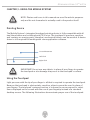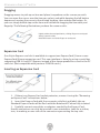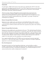
1
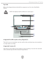
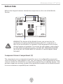
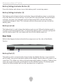
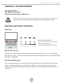
Alienware Area-51® m15x
Note: Specifications and information found in this manual are subject to change
without notice. Any changes therefore will be incorporated in future editions. The
manufacturer assumes no responsibility for errors or omissions in this document.
Reproduction of this manual in any manner without the prior written
permission of Alienware Corporation is strictly prohibited.
Windows™ Vista is the trademark of Microsoft Corporation.
Bluetooth® is the trademark owned by its proprietor.
This product incorporates copyright protect technology that is protected by U.S.
patents and other intellectual property rights. Use of this copyright protect technology
must be authorized by Macrovision, and is intended for home and other limited
viewing uses only unless otherwise authorized by Macrovision. Reverse engineering or
disassembly is prohibited. Other trademarks are properties of their respective owners.
Rev 1.0
OCTOBER 2007
Alienware Area-51® m15x
CONTENTS
Introduction, 5
Chapter 1 System Preparation and Setup, 7
Overview, 8
Standards, 8
Knowing the Parts, 8
Basic sides of the Mobile System, 8
Top Side, 9
Integrated Dual Microphone Array (Built-inDigital), 9
Integrated Camera (on selected models), 9
Display Panel, 10
Power Switch, 10
Instant Keys, 10
Audio Speakers, 10
Keyboard, 10
Touchpad and Buttons, 10
Status Indicators (top), 10
Bottom Side, 11
Component Access Compartment, 11
Battery Voltage Indicator Button, 12
Battery Voltage Indicator, 12
Battery Lock, 12
Rear Side, 12
Battery Pack, 12
Left Side, 13
Power (DC) Input, 13
Audio Output (SPDIF/Digital/Analog/Headphone) Jack, 13
Audio Input/Output Jack (auto sensing), 13
Hi-Speed USB Port (2.0/1.1), 14
Smart Bay Swap Mechanism / Handle, 14
Smart-Bay Optical Disk Drive, 14
Optical Disk Drive Emergency Eject, 14
Gigabit LAN Port, 14
Right Side, 15
Flash Memory Card Reader Slot, 15
ExpressCard Slot, 15
HDMI Port, 15
Alienware Area-51® m15x
IEEE1394B Port (Bilingual), 16
Hi-Speed USB Port (2.0/1.1), 16
Security Lock Port, 16
Chapter 2 Getting started, 18
Switches and Status Indicators, 19
Switches, 19
Bluetooth Key, 19
Wireless LAN Key, 19
Alien Command Center Key, 20
Stealth Mode Key, 20
Status Indicators, 20
Capital Lock Indicator, 20
Number Lock Indicator, 20
Scroll Lock Indicator, 20
Chapter 3
Using the Mobile System, 22
Pointing Device, 23
Using the Touchpad, 23
Moving The Cursor, 24
Scrolling, 24
Touchpad Usage Illustrations, 25
Clicking/Tapping, 25
Double-clicking/Double-tapping, 25
Dragging, 26
Expansion Card, 26
Expansion Card, 26
Inserting an Expansion Card, 26
Removing an Expansion Card, 27
Chapter 4
Declarations and Safety Statements, 29
DVD-ROM Drive Information, 30
Regional Playback Information, 30
Region Definitions, 31
Overview, 32
Federal Communications Commission Statement, 33
FCC Radio Frequency Interference Requirements, 34
FCC Radio Frequency (RF) Exposure Caution Statement, 34
Alienware Area-51® m15x
FCC RF Exposure Guidelines (Wireless Clients), 34
R&TTE Directive (1999/5/EC), 35
CE Mark Warning, 35
Wireless Operation Channel for Different Domains, 35
France Restricted Wireless Frequency Bands, 36
UL Safety Notices, 37
Power Safety Requirement, 37
Nordic Lithium Cautions (for lithium-ion batteries), 38
Optical Drive Safety Information, 39
Laser Safety Information, 39
Service Warning Label, 39
CDRH Regulations, 39
Macrovision Corporation Product Notice, 39
Alienware Area-51® m15x
INTRODUCTION
Dear Valued Alienware Customer,
Welcome to the Alienware family. We are thrilled to include you among the growing
number of savvy high-performance mobile users.
The Alienware technicians who have crafted your machine have made certain that
your high-performance mobile is properly optimized and performs to its fullest
potential. We build machines with one single unwavering purpose: Build It As If
It Were Your Own. The technicians will not rest until your new machine meets or
exceeds our very demanding criteria!
We have tested your machine extensively in order to ensure that you enjoy the
highest levels of performance. In addition to a standard burn-in period, your
system has been evaluated using real-world tools such as synthetic performance
benchmarks.
We invite you to share your experience with your new high-performance mobile
with us, so please do not hesitate to either e-mail or call Alienware with any
questions or concerns. The entire staff shares your enthusiasm for new technology
and we hope that you enjoy using your new Mobile System as much as Alienware
enjoyed building it for you.
Sincerely,
Alienware Staff
Alienware Area-51® m15x
Alienware Area-51® m15x
CHAPTER 1: SYSTEM PREPARATION AND SETUP
Alienware Area-51® m15x
CHAPTER 1: SYSTEM PREPARATION AND SETUP
Overview
Congratulations on the purchase of your Alienware Area-51® m15x!
Standards
The following standards are adopted throughout this manual:
• Mobile System refers to the notebook computer that you have purchased.
• Boldface type is also used to highlight important information in this
document.
• Whenever extra caution is called for, the information will be boxed in a frame
preceded by “NOTE:” or “WARNING:”
Knowing the Parts
Basic Sides of the Mobile System
NOTE: Photos and icons in this manual are used for artistic purposes
only and do not show what is actually used in the product itself.
8
Alienware Area-51® m15x
Top Side
Refer to the diagram below to identify the components on this side of the Mobile
System.
NOTE: The keyboard will be different for each region.
SCRN
CAPS
NUM
Integrated Dual Microphone Array (Digital) (1)
The built-in mono microphones can be used for video conferencing, voice narrations,
or simple audio recordings.
Integrated Camera ()
The built-in camera allows picture taking or video recording. It can also be used with
video conferencing and other interactive applications.
9
Alienware Area-51® m15x
Display Panel (3)
The Mobile System uses an ultra-clear flat panel which provides excellent viewing like
that of desktop monitors without any harmful radiation or flickering, so it is easier on
the eyes. Use a soft cloth without chemical liquids (use plain water if necessary) to
clean the display panel.
WARNING: The display panel is fragile. Do not bend or press on the panel.
Power Switch (4)
The power switch turns the Mobile System ON and OFF and can also put the Mobile
System into sleep or hibernation modes. Actual behavior of the power switch can be
customized in Windows Control Panel “Power Options.”
Instant Keys (5)
Instant keys allow you to launch frequently used applications with one push of a
button. Details are described in section 2.
Audio Speakers (6)
The built-in stereo speaker system allows you to hear audio without additional
attachments. The multimedia sound system features an integrated digital audio
controller that produces rich, vibrant sound (results improved with external stereo
headphones or speakers). Audio features are software controlled.
Keyboard (7)
The keyboard provides full-sized keys with comfortable travel (depth at which the keys
can be depressed) and a palm rest for both hands. A Windows function key is provided
to help ease navigation in the Windows operating system.
Touchpad and Buttons (8)
The touchpad with its buttons is a pointing device that provides the same functions as
a desktop mouse. A software-controlled scrolling function is available after setting up
the included touchpad utility to allow easy Windows or web navigation.
Status Indicators (top) (9)
Status indicators represent various hardware/software conditions. See indicator
details in section 2.
10
Alienware Area-51® m15x
Bottom Side
Refer to the diagram below to identify the components on this side of the Mobile
System.
WARNING! The bottom of the Mobile System can get very hot. Be
careful when handling the Mobile System while it is in operation or
after it has recently been in operation. High temperatures are normal
during charging or operation. Do not use on soft surfaces such as beds
or sofas which may block the vents. DO NOT PUT THE MOBILE SYSTEM
ON YOUR LAP OR OTHER PARTS OF THE BODY TO AVOID INJURY FROM
THE HEAT.
Component Access Compartment (1)
The component access compartment provides access to configurable components
such as hard drive, video graphics card, cpu, and memory. Visit an authorized service
center or retailer for information on component upgrades for your Mobile System. Only
purchase expansion memory modules from authorized retailers of this Mobile System
to ensure maximum compatibility and reliability.
11
Alienware Area-51® m15x
Battery Voltage Indicator Button (2)
Press this button and release to see the battery pack’s remaining power.
Battery Voltage Indicator (3)
The battery pack voltage indicator estimates how much battery power is remaining.
Press the button once and release. One to five LEDs will illuminate. No illumination
indicates no power (not charged) and five illuminated LEDs indicate full power
(completely charged). Note: This indicator will also illuminate once you insert the
battery pack.
Battery Lock (4)
The battery lock is used to keep the battery pack secured. When the battery pack is
inserted, it will automatically lock. To remove the battery pack, slide this spring lock
until the battery pack lifts up slightly and then lift the battery pack out.
Rear Side
Refer to the diagram below to identify the components on this side of the Mobile
System.
Battery Pack (1)
The battery pack is automatically charged when the Mobile System is connected to
an AC power source and maintains power to the Mobile System when AC power is not
connected. This allows use when moving temporarily between locations. Battery time
varies by usage and by the specifications for this Mobile System. The battery pack
cannot be disassembled and must be purchased as a single unit.
12
Alienware Area-51® m15x
Left Side
Refer to the diagram below to identify the components on this side of the Mobile
System.
Power (DC) Input (1)
The supplied power adapter converts AC power to DC power for use with this jack.
Power supplied through this jack supplies power to the Mobile System and charges
the internal battery pack. To prevent damage to the Mobile System and battery pack,
always use the supplied power adapter.
CAUTION: MAY BECOME WARM TO HOT WHEN IN USE. BE SURE NOT TO
COVER THE ADAPTER AND KEEP IT AWAY FROM YOUR BODY.
Audio Output (SPDIF/Digital/Analog/Headphone) Jack ()
The stereo headphone jack (1/8 inch) is used to connect the Mobile System’s audio
out signal to amplified speakers or headphones. Using this jack automatically
disables the built-in speakers.
Audio Input/Output Jack (auto sensing) (3)
The stereo input/output jack (1/8 inch) can be used to connect stereo audio into the
Mobile System or out to a multimedia device. This feature can be used to add audio to
Mobile System applications or output audio to stereo audio equipment. This port also
detects SPDIF audio as well.
13
Alienware Area-51® m15x
Hi-Speed USB Port (2.0/1.1) (4)
The USB (Universal Serial Bus) port is compatible with USB 2.0 or USB 1.1 devices
such as keyboards, pointing devices, cameras, hard disk drives, printers, and scanners
connected in a series up to 12Mbits/sec (USB 1.1) and 480Mbits/sec (USB 2.0). USB
allows many devices to run simultaneously on a single computer, with some peripherals
acting as additional plug-in sites or hubs. USB supports hot-swapping of devices so that
most peripherals can be connected or disconnected without restarting the computer.
Smart Bay Swap Mechanism / Handle (5)
The optical drive swap handle allows easy removal of the optical drive. Press and
release to extend the handle. Then pull on the handle to remove the drive.
Smart-Bay Optical Disk Drive (6)
The Mobile System comes in various models with different smart bay drives. The
Mobile System’s smart bay drive may support compact discs (CD), digital video discs
(DVD), recordable (R), writable (W), secondary batteries or an additional hard drive.
See the marketing specifications for details on each model. To eject the smart by drive,
press the button on the bottom right of the drive to extend the latch. Once the latch is
extended, gently pull the smart bay out of the opening.
Optical Disk Drive Emergency Eject (location varies by model) (7)
The emergency eject is used to eject the optical drive tray in case the electronic eject
does not work. Do not use the emergency eject in place of the electronic eject.
Gigabit LAN Port (8)
The RJ-45 LAN port supports a standard Ethernet cable for connection to a local
network. The built-in connector allows convenient use without additional adapters.
14
Alienware Area-51® m15x
Right Side
Refer to the diagram below to identify the components on this side of the Mobile
System.
Flash Memory Card Reader Slot (1)
Normally, an external memory card reader must be purchased separately in order to
use memory cards from devices such as digital cameras, MP3 players, mobile phones,
and PDAs. This Mobile System has a built-in high-speed memory card reader that can
conveniently read from and write to many flash memory cards as mentioned later in
this manual. This slot will support MMC, SD, MS and MS Pro media.
ExpressCard Slot (2)
One 26pin Express card slot is available to support one ExpressCard/34mm or one
ExpressCard/54mm expansion card. This new interface is faster by using a serial bus
supporting USB 2.0 and PCI Express instead of the slower parallel bus used in the PC
card slot. (Not compatible with previous PCMCIA cards.)
HDMI Port (3)
HDMI (High-Definition Multimedia Interface) is an uncompressed all-digital audio/
video interface between any audio/video source, such as a set-top box, DVD player,
and A/V receiver and an audio and/or video monitor, such as a digital television (DTV).
HDMI supports standard, enhanced, or high-definition video, plus multi-channel
digital audio on a single cable. It transmits all ATSC HDTV standards and supports 8channel digital audio with bandwidth to spare to accommodate future enhancements
or requirements.enhancements or requirements.
15
Alienware Area-51® m15x
IEEE1394B Port (Bilingual) (4)
IEEE1394 is a high speed serial bus like SCSI but has simple connections and hotplugging capabilities like USB. The interface 1394A has a bandwidth up to 400 Mbits/
sec and 1394B up to 800 Mbits/sec. They both can handle many 1394 devices on the
same bus. IEEE1394 is also used in high-end digital equipment and should be marked
“DV” for Digital Video port. This is a bilingual port so it can function with both 1394A &
1394B devices at the speeds listed above respectively.
Hi-Speed USB Port (2.0/1.1) (5)
The USB (Universal Serial Bus) port is compatible with USB 2.0 or USB 1.1 devices
such as keyboards, pointing devices, cameras, hard disk drives, printers, and scanners
connected in a series up to 12Mbits/sec (USB 1.1) and 480Mbits/sec (USB 2.0). USB
allows many devices to run simultaneously on a single computer, with some peripherals
acting as additional plug-in sites or hubs. USB supports hot-swapping of devices so that
most peripherals can be connected or disconnected without restarting the computer.
Security Lock Port (6)
The Kensington® lock port allows the Mobile System to be secured using Kensington®
compatible Mobile System security products. These security products usually include
a metal cable and lock that prevent the Mobile System from being removed from
a fixed object. Some may also include a motion detector to sound an alarm when
moved.
16
Alienware Area-51® m15x
17
Alienware Area-51® m15x
CHAPTER 2: Getting started
18
Alienware Area-51® m15x
CHAPTER 2: GETTING STARTED
Using AC Power
Using Battery Power
Switches and Status Indicators
NOTE: Photos and icons in this manual are used for artistic purposes
only and do not show what is actually used in the product itself.
Switches and Status Indicators
Switches
Minus Icon (touch panel):
Decreases the speaker audio volume.
Plus Icon (touch panel):
Increases the speaker audio volume.
Bluetooth Key (1)
The Bluetooth key toggles the internal Bluetooth ON and OFF. An on-screen display
and relevant status indicator will show that the Mobile System’s built-in Bluetooth (BT)
function is activated.
Wireless LAN Key ()
This is only applicable on models with internal Wireless LAN. The Wireless LAN key
toggles the internal Wireless LAN ON and OFF. An on-screen display and relevant
status indicator will show that the Mobile System’s built-in Wireless LAN function is
activated.
19
Alienware Area-51® m15x
Alien Command Center Key (3)
Press this key to start the Alien Command Center application.
Stealth Mode Key (4)
Press this key to go into stealth mode. In stealth mode your system will not exceed
65w of power draw which will allow your system to operate in power limited
environments (e.g. airplanes, DC/AC convertors). While in stealth mode your system
may not have all of the functionalities available.
Status Indicators
Capital Lock Indicator (1)
Indicates that the keyboard is in capital mode. Capital mode allows you to type letters
in uppercase. Capital or lowercase mode is toggled using CAPS LOCK on the left of the
keyboard.
Number Lock Indicator ()
Indicates that the keyboard is in number lock mode. Number lock allows you to enter
numbers using the number keys on the right of the keyboard. Num¬ber lock mode is
toggled using NUM LOCK on the right of the keyboard. When the number lock indicator
is OFF, the number keys on the right of the keyboard act as up/down/left/right
navigation keys.
Scroll Lock Indicator (3)
Indicates that the keyboard is in scroll lock mode. Scroll lock allows you to use the
keys on the keyboard as up/down/left/right for navigation within a group of items or
cells. Scroll lock mode is toggled using [FN] [SCR LK] on the keyboard.
0
Alienware Area-51® m15x
21
Alienware Area-51® m15x
CHAPTER 3: USING THE MOBILE SYSTEM
22
Alienware Area-51® m15x
CHAPTER 3: USING THE MOBILE SYSTEM
NOTE: Photos and icons in this manual are used for artistic purposes
only and do not show what is actually used in the product itself.
Pointing Device
The Mobile System’s integrated touchpad pointing device is fully compatible with all
two/three-button and scrolling knob PS/2 mice. The touchpad is pressure-sensitive
and contains no moving parts; therefore, mechanical failures can be avoided. A device
driver is still required for working with some application software.
Cursor Movement
Left Click
Right Click
IMPORTANT! Do not use any objects in place of your finger to operate
the touchpad or else damage may occur to the touchpad’s surface.
Using the Touchpad
Light pressure with the tip of your finger is all that is required to operate the touchpad.
Because the touchpad is electrostatic-sensitive, objects cannot be used in place of
your fingers. The touchpad’s primary function is to move the cursor around or select
items displayed on the screen with the use of your fingertip instead of a standard
desktop mouse. The following illustrations demonstrate proper use of the touchpad.
3
Alienware Area-51® m15x
Moving The Cursor
Place your finger in the center of the touchpad and slide in a direction to move the cursor.
Slide finger forward
Slide finger right
Slide finger left
Slide finger backward
Scrolling
Slide your finger up or down on the right side to scroll a window up or down.
24
Alienware Area-51® m15x
Touchpad Usage Illustrations
Clicking/Tapping
With the cursor over an item, press the left button or use your fingertip to touch the
touchpad lightly, keeping your finger on the touchpad until the item is selected. The
selected item will change color. The following 2 examples produce the same results.
Lightly but rapidly strike the touchpad.
Press the left cursor button and release.
Double-clicking/Double-tapping
This is a common skill for launching a program directly from the corresponding icon
you select. Move the cursor over the icon you wish to execute, press the left button
or tap the pad twice in rapid succession, and the system launches the corresponding
program. If the interval between the clicks or taps is too long, the operation will not
be executed. You can set the double-click speed using the Windows Control Panel’s
“Mouse” section. The following 2 examples produce the same results.
Lightly but rapidly strike the touchpad twice.
Press the left button twice and release.
25
Alienware Area-51® m15x
Dragging
Dragging means to pick up an item and place it anywhere on the screen you wish.
You can move the cursor over the item you select, and while keeping the left button
depressed, moving the cursor to the desired location, then release the button. Or,
you can simply double-tap on the item and hold while dragging the item with your
fingertip. The following illustrations produce the same results.
Lightly strike the touchpad twice, sliding finger on touchpad
during second strike.
Hold left button and slide finger on touchpad.
Expansion Card
One 26pin Express card slot is available to support one ExpressCard/34mm or one
ExpressCard/54mm expansion card. This new interface is faster by using a serial bus
supporting USB 2.0 and PCI Express instead of the slower parallel bus used in the PC
card slot. (Not compatible with previous PCMCIA cards.)
Inserting an Expansion Card
1. If there is an ExpressCard socket protector, remove it using the “Removing
an ExpressCard” instructions below.
2. Insert the ExpressCard with the connector side first and label side up.
Standard ExpressCards will be flush with the Notebook PC when fully inserted.
3. Carefully connect any cables or adapters needed by the ExpressCard.
Usually connectors can only be inserted in one orientation. Look for a sticker,
icon, or marking on one side of the connector representing the top side.
26
Alienware Area-51® m15x
Removing an Expansion Card
The ExpressCard slot does not have an eject but¬ton. Press the ExpressCard inwards
and release to eject the ExpressCard. Carefully pull the ejected ExpressCard out of the
socket.
27
Alienware Area-51® m15x
28
Alienware Area-51® m15x
CHAPTER 4: DECLARATIONS AND SAFETY STATEMENTS
29
Alienware Area-51® m15x
CHAPTER 4: DECLARATIONS AND SAFETY STATEMENTS
NOTE: Photos and icons in this manual are used for artistic purposes
only and do not show what is actually used in the product itself.
DVD-ROM Drive Information
The Mobile System comes with an optional DVD-ROM drive or a CD-ROM drive. In
order to view DVD titles, you must install your own DVD viewer software. Optional DVD
viewer software may be purchased with this Mobile System. The DVD-ROM drive allows
the use of both CD and DVD discs.
Regional Playback Information
Playback of DVD movie titles involves decoding MPEG2 video, digital AC3 audio and
decryption of CSS protected content. CSS (sometimes called copy guard) is the name
given to the content protection scheme adopted by the motion picture industry to
satisfy a need to protect against unlawful content duplication.
Although the design rules imposed on CSS licensors are many, one rule that is
most relevant is playback restrictions on regionalized content. In order to facilitate
geographically staggered movie releases, DVD video titles are released for specific
geographic regions as defined in “Region Definitions” below. Copyright laws require
that all DVD movies be limited to a particular region (usually coded to the region at
which it is sold). While DVD movie content may be released for multiple regions, CSS
design rules require that any system capable of playing CSS encrypted content must
only be capable of playing one region.
NOTE: The region setting may be changed up to five times using the
viewer software, then it can only play DVD movies for the last region
setting. Changing the region code after that will require factory
resetting which is not covered by warranty. If resetting is desired,
shipping and resetting costs will be at the expense of the user.
30
Alienware Area-51® m15x
Region Definitions
Region 1
Canada, US, US Territories
Region 2
Czech, Egypt, Finland, France, Germany, Gulf States, Hungary, Iceland, Iran, Iraq,
Ireland, Italy, Japan, Netherlands, Norway, Poland, Portugal, Saudi Arabia, Scotland,
South Africa, Spain, Sweden, Switzer¬land, Syria, Turkey, UK, Greece, Former Yugoslav
Republics, Slovakia
Region 3
Burma, Indonesia, South Korea, Malaysia, Philippines, Singapore, Taiwan, Thailand,
Vietnam
Region 4
Australia, Caribbean (Except US Territories), Central America, New Zealand, Pacific
Islands, South America
Region 5
CIS, India, Pakistan, Rest of Africa, Russia, North Korea
Region 6
China
31
Alienware Area-51® m15x
Overview
On 4th August 1998 the European Council Decision regarding the CTR 21 has been
published in the Official Journal of the EC. The CTR 21 applies to all non voice terminal
equipment with DTMF-dialling which is intended to be connected to the analogue
PSTN (Public Switched Telephone Network).
CTR 21 (Common Technical Regulation) for the attachment requirements for
connection to the analogue public switched telephone networks of terminal
equipment (excluding terminal equipment supporting the voice telephony justified
case service) in which network addressing, if provided, is by means of dual tone
multifrequency signalling.
Network Compatibility Declaration
Statement to be made by the manufacturer to the Notified Body and the vendor:
“This declaration will indicate the networks with which the equipment is designed
to work and any notified networks with which the equipment may have inter-working
difficulties”
Network Compatibility Declaration
Statement to be made by the manufacturer to the user: “This declaration will indicate
the networks with which the equipment is designed to work and any notified networks
with which the equipment may have inter-working difficulties. The manufacturer shall
also associate a statement to make it clear where network compatibility is dependent
on physical and software switch settings. It will also advise the user to contact the
vendor if it is desired to use the equipment on another network.”
Up to now the Notified Body of CETECOM issued several pan-European approvals
using CTR 21. The results are Europe’s first modems which do not require regulatory
approvals in each individual European country.
Non-Voice Equipment
Answering machines and loud-speaking telephones can be eligible as well as
modems, fax machines, auto-dialers and alarm systems. Equipment in which the endto-end quality of speech is controlled by regulations (e.g. handset telephones and in
some countries also cordless telephones) is excluded.
32
Alienware Area-51® m15x
Federal Communications Commission Statement
This device complies with FCC Rules Part 15. Operation is subject to the following two
conditions:
•
•
This device may not cause harmful interference, and
This device must accept any interference received, including interference
that may cause undesired operation.
This equipment has been tested and found to comply with the limits for a class B
digital device, pursuant to Part 15 of the Federal Communications Commission (FCC)
rules. These limits are designed to provide reasonable protection against harmful
interference in a residential installation. This equipment generates, uses, and can
radiate radio frequency energy and, if not installed and used in accordance with the
instructions, may cause harmful interference to radio communications. However,
there is no guarantee that interference will not occur in a particular installation. If this
equipment does cause harmful interference to radio or television reception, which can
be determined by turning the equipment off and on, the user is encouraged to try to
correct the interference by one or more of the following measures:
•
•
•
•
Reorient or relocate the receiving antenna.
Increase the separation between the equipment and receiver.
Connect the equipment into an outlet on a circuit different from that to
which the receiver is connected.
Consult the dealer or an experienced radio/TV technician for help.
WARNING! The use of a shielded-type power cord is required in order
to meet FCC emission limits and to prevent interference to the nearby
radio and television recep¬tion. It is essential that only the supplied
power cord be used. Use only shielded cables to connect I/O devices
to this equipment. You are cautioned that changes or modifications
not expressly approved by the party responsible for compliance could
void your authority to operate the equipment.
(Reprinted from the Code of Federal Regulations #47, part 15.193, 1993. Washington
DC: Office of the Federal Register, National Archives and Records Administration, U.S.
Government Printing Office.)
33
Alienware Area-51® m15x
FCC Radio Frequency Interference Requirements
This device is restricted to INDOOR USE due to its operation in the 5.15 to 5.25GHz
frequency range. FCC requires this product to be used indoors for the frequency
range 5.15 to 5.25GHz to reduce the potential for harmful interference to co-channel
of the Mobile Satellite Systems.
High power radars are allocated as primary user of the 5.25 to 5.35GHz and 5.65 to
5.85GHz bands. These radar stations can cause interference with and / or damage
this device.
IMPORTANT: This device and its antenna(s) must not be co-located or
operating in conjunction with any other antenna or transmitter.
FCC Radio Frequency (RF) Exposure Caution Statement
This equipment complies with FCC RF exposure limits set forth for an uncontrolled
environment. To maintain compliance with FCC RF exposure compliance requirements,
please follow operation instruc¬tions in the user’s manual. This equipment is for
operation within 5.15 GHz and 5.25GHz frequency ranges and is restricted to indoor
environments only.
FCC Caution: Any changes or modifications not expressly approved by
the party re¬sponsible for compliance could void the user’s authority
to operate this equipment. “The manufacturer declares that this
device is limited to Channels 1 through 11 in the 2.4GHz frequency by
specified firmware controlled in the USA.”
FCC RF Exposure Guidelines (Wireless Clients)
This device has been tested for compliance with FCC RF Exposure (SAR) limits in typical
portable configurations. In order to comply with SAR limits established in the ANSI
C95.1 standards, it is recom¬mended when using a wireless LAN adapter that the
integrated antenna is positioned more than [20cm] from your body or nearby persons
during extended periods of operation. If the antenna is positioned less than [20cm]
from the user, it is recommended that the user limit the exposure time.
34
Alienware Area-51® m15x
R&TTE Directive (1999/5/EC)
The following items were completed and are considered relevant and sufficient for the
R&TTE (Radio & Telecommunications Terminal Equipment) directive:
•
•
•
•
•
•
•
•
Essential requirements as in [Article 3]
Protection requirements for health and safety as in [Article 3.1a]
Testing for electric safety according to [EN 60950]
Protection requirements for electromagnetic compatibility in [Article 3.1b]
Testing for electromagnetic compatibility in [EN 301 489-1] & [EN 301]
Testing according to [489-17]
Effective use of the radio spectrum as in [Article 3.2]
Radio test suites according to [EN 300 328-2]
CE Mark Warning
This is a Class B product, in a domestic environment, this product may cause radio
interference, in which case the user may be required to take adequate measures.
Wireless Operation Channel for Different Domains
N. America
Japan
Europe ETSI
2.412-2.462 GHz
2.412-2.484 GHz
2.412-2.472 GHz
35
Ch01 through CH11
Ch01 through Ch14
Ch01 through Ch13
Alienware Area-51® m15x
France Restricted Wireless Frequency Bands
Some areas of France have a restricted frequency band. The worst case maximum
authorized power indoors are:
•
•
10mW for the entire 2.4 GHz band (2400 MHz–2483.5 MHz)
100mW for frequencies between 2446.5 MHz and 2483.5 MHz
NOTE: Channels 10 through 13 inclusive operate in the band 2446.6
MHz to 2483.5 MHz.
There are few possibilities for outdoor use: On private property or on the private
property of public persons, use is subject to a preliminary authorization procedure by
the Ministry of Defense, with maxi¬mum authorized power of 100mW in the 2446.5–
2483.5 MHz band. Use outdoors on public property is not permitted.
In the departments listed below, for the entire 2.4 GHz band:
•
•
Maximum authorized power indoors is 100mW
Maximum authorized power outdoors is 10mW
Departments in which the use of the 2400–2483.5 MHz band is permitted with an
EIRP of less than 100mW indoors and less than 10mW outdoors:
01 Ain Orientales
08 Ardennes
16 Charente
32 Gers
45 Loiret
59 Nord
64 Pyrénées Atlantique
70 Haute Saône
84 Vaucluse
94 Val de Marne
02 Aisne
03 Allier
05 Hautes Alpes
09 Ariège
11 Aude
12 Aveyron
24 Dordogne
25 Doubs
26 Drôme
36 Indre
37 Indre et Loire
41 Loir et Cher
50 Manche
55 Meuse
58 Nièvre
60 Oise
61 Orne
63 Puy du Dôme
66 Pyrénées
67 Bas Rhin
68 Haut Rhin
71 Saône et Loire75 Paris
82 Tarn et Garonne
88 Vosges 89 Yonne
90 Territoire de Belfort
This requirement is likely to change over time, allowing you to use your wireless LAN
card in more areas within France. Please check with ART for the latest information
(www.art-telecom.fr)
NOTE: Your WLAN Card transmits less than 100mW, but more than
10mW.
3
Alienware Area-51® m15x
UL Safety Notices
Required for UL 1459 covering telecommunications (telephone) equipment intended
to be electrically connected to a telecommunication network that has an operating
voltage to ground that does not exceed 200V peak, 300V peak-to-peak, and 105V rms,
and installed or used in accordance with the National Electrical Code (NFPA 70).
When using the Notebook PC modem, basic safety precautions should always be
followed to reduce the risk of fire, electric shock, and injury to persons, including the
following:
•
•
•
Do not use the Notebook PC near water, for example, near a bath tub, wash
bowl, kitchen sink or laundry tub, in a wet basement or near a swimming pool.
Do not use the Notebook PC during an electrical storm. There may be a
remote risk of electric shock from lightning.
Do not use the Notebook PC in the vicinity of a gas leak.
Required for UL 1642 covering primary (non-rechargeable) and secondary
(rechargeable) lithium batter¬ies for use as power sources in products. These batteries
contain metallic lithium, or a lithium alloy, or a lithium ion, and may consist of a single
electrochemical cell or two or more cells connected in series, parallel, or both, that
convert chemical energy into electrical energy by an irreversible or reversible chemical
reaction.
•
•
DO NOT dispose the Notebook PC battery pack in a fire, as they may
explode.
Check with local codes for possible special disposal instructions to reduce
the risk of injury to persons due to fire or explosion.
DO NOT use power adapters or batteries from other devices to reduce the
risk of injury to per¬sons due to fire or explosion. Use only UL certified
power adapters or batteries supplied by the manufacturer or authorized
retailers.
Power Safety Requirement
Products with electrical current ratings up to 6A and weighing more than 3Kg must use
approved power cords greater than or equal to: H05VV-F, 3G, 0.75mm2 or H05VV-F,
2G, 0.75mm2.
37
Alienware Area-51® m15x
Nordic Lithium Cautions (for lithium-ion batteries)
CAUTION! Danger of explosion if battery is incorrectly replaced.
Replace only with the same or equivalent type recommended
by the manufacturer. Dispose of used batteries according to the
manufacturer’s instructions. (English)
ATTENZIONE! Rischio di esplosione della batteria se sostituita in modo
errato. Sosti¬tuire la batteria con un una di tipo uguale o equivalente
consigliata dalla fabbrica. Non disperdere le batterie nell’ambiente.
(Italian)
VORSICHT! Explosionsgetahr bei unsachgemäßen Austausch der
Batterie. Ersatz nur durch denselben oder einem vom Hersteller
empfohlenem ähnlichen Typ. Entsorgung gebrauchter Batterien nach
Angaben des Herstellers. (German)
ADVARSELI! Lithiumbatteri - Eksplosionsfare ved fejlagtig håndtering.
Udskiftning må kun ske med batteri af samme fabrikat og type. Levér
det brugte batteri tilbage til leverandøren. (Danish)
VARNING! Explosionsfara vid felaktigt batteribyte. Använd
samma batterityp eller en ekvivalent typ som rekommenderas av
apparattillverkaren. Kassera använt batteri enligt fabrikantens
instruktion. (Swedish)
VAROITUS! Paristo voi räjähtää, jos se on virheellisesti asennettu.
Vaihda paristo aino¬astaan laitevalmistajan sousittelemaan tyyppiin.
Hävitä käytetty paristo valmistagan ohjeiden mukaisesti. (Finnish)
ATTENTION! Il y a danger d’explosion s’il y a remplacement incorrect de
la bat¬terie. Remplacer uniquement avec une batterie du mêre type ou
d’un type équivalent recommandé par le constructeur. Mettre au rebut
les batteries usagées conformément aux instructions du fabricant.
(French)
ADVARSEL! Eksplosjonsfare ved feilaktig skifte av batteri.
Benytt samme batteritype eller en tilsvarende type anbefalt
av apparatfabrikanten. Brukte batterier kasseres i henhold til
fabrikantens instruksjoner. (Norwegian)
(Japan)
38
Alienware Area-51® m15x
Optical Drive Safety Information
Laser Safety Information
Internal or external optical drives sold with this Notebook PC contains a CLASS 1
LASER PRODUCT. Laser classifications can be found in the glossary at the end of this
user’s manual.
WARNING: Making adjustments or performing procedures other than
those specified in the user’s manual may result in hazardous laser
exposure. Do not attempt to disas¬semble the optical drive. For your
safety, have the optical drive serviced only by an authorized service
provider.
Service Warning Label
CAUTION: Invisible laser radiation when open. Do not stare into beam
or view directly with optical instruments.
CDRH Regulations
The Center for Devices and Radiological Health (CDRH) of the U.S. Food and Drug
Administration imple¬mented regulations for laser products on August 2, 1976. These
regulations apply to laser products manu¬factured from August 1, 1976. Compliance
is mandatory for products marketed in the United States.
WARNING: Use of controls or adjustments or performance of
procedures other than those specified herein or in the laser product
installation guide may result in hazard¬ous radiation exposure.
Macrovision Corporation Product Notice
This product incorporates copyright protection technology that is protected by method
claims of certain U.S.A. patents and other intellectual property rights owned by
Macrovision Corporation and other rights owners. Use of this copyright protection
technology must be authorized by Macrovision Corporation, and is intended for home
and other limited viewing uses only unless otherwise authorized by Macrovision
Corporation. Reverse engineering or disassembly is prohibited.
39