1
WARRANTY
Wavetek-Datron warrants that all products manufactured by Wavetek-Datron conform to published
Wavetek-Datron specifications and are free from defects in material and workmanship for a period of one
(1) year from the date of delivery when used under normal conditions and within the service conditions
for which they were furnished.
The obligation of Wavetek-Datron arising from a Warranty claim shall be limited to repairing, or at its
option, replacing without charge, any product which in Wavetek-Datron’s sole opinion proves to be defective
within the scope of the Warranty. In the event Wavetek-Datron is not able to modify, repair or replace
non-conforming defective parts or components to the condition as warranted within a reasonable time after
receipt thereof, Buyers shall be credited for their value at the original purchase price.
Wavetek-Datron must be notified in writing of the defect or nonconformity within the Warranty period and
the affected product returned to Wavetek-Datron’s factory or to an authorized service center within thirty
(30) days after discovery of such defect or nonconformity.
For products warranties requiring return to Wavetek-Datron, products must be returned to a service facility
designated by Wavetek-Datron. Buyer shall prepay shipping charges, taxes, duties and insurance for
products returned to Wavetek-Datron for warranty service. Except for products returned to Buyer from
another country, Wavetek-Datron shall pay for return of product to Buyer.
Wavetek-Datron shall have no responsibility hereunder for any defect or damage caused by improper
storage, improper installation, unauthorized modification, misuse, neglect, inadequate maintenance, accident
or for any product which has been repaired or altered by anyone other than Wavetek-Datron or its
authorized representative and not in accordance with instructions furnished by Wavetek-Datron.
Exclusion of Other Warranties
The Warranty described above is Buyer’s sole and exclusive remedy and no other warranty, whether
written or oral, is expressed or implied. Wavetek-Datron specifically disclaims the implied warranties
of merchantability and fitness for a particular purpose. No statement, representation, agreement, or
understanding, oral or written, made by an agent, distributor, representative, or employee of Wavetek-Datron,
which is not contained in the foregoing Warranty will be binding upon Wavetek-Datron, unless made in
writing and executed by an authorized Wavetek-Datron employee. Under no circumstances shall
Wavetek-Datron be liable for any direct, indirect, special, incidental, or consequential damages,
expenses, losses or delays (including loss of profits) based on contact, tort, or any other legal
theory.
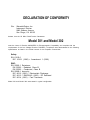
DECLARATION OF CONFORMITY
We:
Wavetek-Datron Inc.
Instrument Division
9045 Balboa Avenue
San Diego, CA 92123
declare, that the 50 MHz Pulse/Function Generators
Model 301 and Model 302
meet the intent of Directive 89/336/EEC for Electromagnetic Compatibility and complies with the
requirements of the Low Voltage Directive 73/23/EEC. Compliance was demonstrated to the following
specifications as listed in the official Journal of the European Communities:
Safety:
EN 61010-1
IEC 1010-1 (1990) + Amendment 1 (1992)
EMC:
EN 50081-1
EN 55022
EN 55022
EN 50082-1
IEC 801-2
IEC 801-3
IEC 801-4
Emissions:
- Radiated, Class B
- Conducted, Class B
Immunity:
(1991) - Electrostatic Discharge
/ ENV50140 (1993) - RF Radiated
(1991) - Fast Transients
Model 301 and Model 302 were tested in typical configuration.
SAFETY PRECAUTIONS
Protect yourself. Follow these precautions:
•
Don’t bypass the power cord’s ground lead with two-wire extension cords or plug
adapters.
•
Don’t disconnect the green and yellow safety-earth-ground wire that connects the
ground lug of the power receptacle to the chassis ground terminal (marked with
or
•
Don’t plug in the power cord until directed to by the installation instructions.
•
Don’t repair the instrument unless you are qualified electronics technician and know
how to work with hazardous voltages.
•
Pay attention to the WARNING statements. They point out situations that can cause
injury or death.
•
Pay attention to the CAUTION statements. They point out situations that can cause
equipment damage.
The American National Standard Institute (ANSI) states that a shock hazard exists when voltage levels
greater than 30V RMS, 42.4V peak, or 60 VDC are present. A good safety practice is to expect that
hazardous voltage is present in any unknown circuit before touching or disconnecting the line cord. Before
operating this instrument, make sure the line cord is connected to a properly grounded power receptacle.
Inspect the connecting cables and test leads for possible wear, cracks, or breaks before each use.
For maximum safety, do not touch the product, test cables, or any other of the instrument parts while
power is applied to the circuit under test. ALWAYS remove power from the entire test system before
connecting cables or jumpers, or making internal changes. Do not touch any object that could provide a
current path to the common side of the circuit under test or power line (earth) ground. Always keep dry
hands while handling the instrument. If you are using test fixtures, keep the lid closed while power is
applied to the device under test. Safe operation requires that the instrument covers be closed at all times
during operation.
Carefully read the Safety Precautions instructions that are supplied with your instrument. Instruments, cables,
leads or cords should not be connected to humans. Before performing any maintenance, disconnect the
line cord and all test cables.
301/302 User Manual
Table of Contents
Table of Contents ................................................................................................................................ 1
Table of Figures .................................................................................................................................. 1
Getting Started .................................................................................................................................... 1
What’s In This Chapter ............................................................................................................................. 1
Introduction ................................................................................................................................................ 2
Options ........................................................................................................................................................ 3
Safety Considerations ................................................................................................................................ 4
Supplied Accessories .................................................................................................................................. 4
Specifications .............................................................................................................................................. 4
Functional Description............................................................................................................................... 4
Input and Output Connectors ..................................................................................................................................... 5
Main Output - Channel A ...................................................................................................................................... 5
Auxiliary Output - Channel A (I)........................................................................................................................... 5
Main Output - Channel B....................................................................................................................................... 5
Auxiliary Output - Channel B (Q) ......................................................................................................................... 5
SYNC Output......................................................................................................................................................... 5
Trigger Input.......................................................................................................................................................... 5
AM Input - Channel A ........................................................................................................................................... 6
AM Input - Channel B ........................................................................................................................................... 6
Sample Clock Input ............................................................................................................................................... 6
Operating Modes ....................................................................................................................................................... 6
Continuous Mode................................................................................................................................................... 6
Triggered Mode ..................................................................................................................................................... 7
Burst Mode ............................................................................................................................................................ 7
Gated Mode ........................................................................................................................................................... 7
Output Type ........................................................................................................................................................... 7
Standard (Fixed) Waveforms ..................................................................................................................................... 8
Arbitrary (User) Waveforms...................................................................................................................................... 8
Sequenced Waveforms .............................................................................................................................................. 9
Output State.............................................................................................................................................. 11
Filters......................................................................................................................................................... 11
Front Panel Indicators ............................................................................................................................. 11
Programming The Model 301/302 .......................................................................................................... 11
CONFIGURING The INSTRUMENT............................................................................................ 12
Installation Overview ............................................................................................................................... 12
Unpacking and Initial Inspection ............................................................................................................................. 12
Safety Precautions ................................................................................................................................................... 12
Performance Checks ................................................................................................................................................ 13
Power Requirements ................................................................................................................................................ 13
Grounding Requirements ...........................................................................................................................................14
Table of Contents
301/302 User Manual
Long Term Storage or Repackaging For Shipment.................................................................................................. 14
Preparation For Use ................................................................................................................................. 15
Logical Address Selection ....................................................................................................................................... 15
Installation ............................................................................................................................................................... 16
Bench Operation ...................................................................................................................................................... 16
Rack Mounting ........................................................................................................................................................ 16
USING The INSTRUMENT............................................................................................................17
Overview.................................................................................................................................................... 17
Inter-Channel Dependency ...................................................................................................................................... 17
Output Termination.................................................................................................................................................. 17
Input / Output Protection ...........................................................................................................................................17
Power On/Reset Defaults......................................................................................................................................... 18
Programming the 301/302 ........................................................................................................................ 18
Controlling the 301/2 Using WaveWiz.................................................................................................... 20
Controlling Instrument Functions .......................................................................................................... 22
Using the APPLy Command.................................................................................................................................... 22
Selecting the Active Channel................................................................................................................................... 25
Enabling the Main Outputs ...................................................................................................................................... 26
Selecting an Output Type ........................................................................................................................................ 27
Selecting a Standard Function Shape....................................................................................................................... 28
Changing the Frequency and Sample Clock ............................................................................................................ 31
Selecting the External SCLK ................................................................................................................................... 32
Programming the Output Amplitude and Offset ...................................................................................................... 33
Selecting the Filter Type.......................................................................................................................................... 34
Selecting an Operating Mode................................................................................................................................... 35
Enabling the SYNC Output ..................................................................................................................................... 40
Assigning the Source for the SYNC Output ............................................................................................................ 41
Selecting the SYNC Position ................................................................................................................................... 42
Generating Arbitrary Waveforms........................................................................................................... 42
What Are Arbitrary Waveforms?............................................................................................................................. 43
Arbitrary Memory Management .............................................................................................................................. 44
Memory Management Commands........................................................................................................................... 44
Loading ArbitraryWaveforms.................................................................................................................................. 45
Reversing Byte Order ............................................................................................................................................ 457
Using the DMA ....................................................................................................................................................... 47
Using WaveWiz to Generate Arbitrary Waveforms ................................................................................................ 48
Using standard Waveforms to Generate Arbitrary Waveforms ............................................................................... 49
Using Waveform drawing and editing tools to generate arbitrary waveforms......................................................... 50
Using Equation Editor to Generate Arbitrary Waveforms ....................................................................................... 51
Using Previously Saved Waveforms to Generate Arbitrary Waveforms ................................................................. 56
Using Files From Other Applications to Generate Waveforms ............................................................................... 56
Sequenced Waveforms ............................................................................................................................. 58
What Are Sequenced Waveforms? .......................................................................................................................... 58
Sequence Commands ............................................................................................................................................... 58
Fast Binary Sequence Table Download ................................................................................................................... 61
Using WaveWiz to Generate Sequences ................................................................................................. 62
Downloading Segments ........................................................................................................................................... 62
Selecting Number of Sequences .............................................................................................................................. 62
Selecting active Sequence........................................................................................................................................ 63
Running Sequences Using WaveWiz .................................................................................................................... 64
Table of Contents
301/302 User Manual
Generating Sequenced Sequences ........................................................................................................... 65
What Are Sequenced Sequences?............................................................................................................................ 65
Sequence Advance Commands................................................................................................................................ 66
Sequence Advance Source Commands.................................................................................................................... 67
Generating Sequenced Sequences with WaveWiz.................................................................................................. 68
Adjusting Phase Offset Between Channels ............................................................................................ 73
Amplitude Modulation Commands ........................................................................................................ 75
System-Related Commands..................................................................................................................... 75
SCPI Commands from WaveWiz ........................................................................................................... 76
SCPI COMMAND REFERENCE .................................................................................................. 78
Introduction .............................................................................................................................................. 78
SCPI Syntax and Styles...............................................................................................................................78
Quering Parameter Setting....................................................................................................................................... 77
Query Response Format........................................................................................................................................... 78
IEEE-STD-488.2 Common Commands ................................................................................................................... 78
SOURce Subsystem ....................................................................................................................................84
OUTPut Subsystem .....................................................................................................................................95
FORMat Subsystem ....................................................................................................................................98
INSTrument Subsystem ..............................................................................................................................99
Trigger Subsystem.....................................................................................................................................100
TRACe Subsystem ....................................................................................................................................103
SYSTem Subsystem ..................................................................................................................................107
IEEE-STD-488.2 Common Commands and Queries ................................................................................108
The SCPI Status Registers ..................................................................................................................................... 108
The Status Byte Register........................................................................................................................................ 109
Reading the Status Byte Register........................................................................................................................... 111
Clearing the Status Byte Register .......................................................................................................................... 111
Service Request Enable Register (SRE) ................................................................................................................ 111
Standard Event Status Register (ESR) ................................................................................................................... 112
Standard Event Status Enable Register (ESE) ....................................................................................................... 113
Error Messages ...................................................................................................................................................... 113
Device Specific Commands ................................................................................................................................... 116
Appendix A SPECIFICATIONS ....................................................................................................... i
Table of Contents
301/302 User Manual
Table of Figures
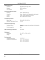
Figure 1.1, Model 301/302 ................................................................................................................................................ 1
Figure 1.1a, Segment 1 – Sin (x)/x Waveform .................................................................................................................. 9
Figure 1.1b, Segment 2 – Sine Waveform ....................................................................................................................... 10
Figure 1.1c, Segment 3 – Pulse Waveform...................................................................................................................... 10
Figure 1.1d, Sequenced Waveforms ................................................................................................................................ 10
Figure 2.1, Setting Logical Address ................................................................................................................................ 15
Figure 3.1, Default Conditions After Power On or After *RST ...................................................................................... 18
Figure 3.2, Reset button on the System Tab .................................................................................................................... 20
Figure 3.3, Adjusting Standard Waveform types and Parameters.................................................................................... 21
Figure 3.4, Turning on Outputs ....................................................................................................................................... 21
Figure 3.5, Select active channel by clicking on Chan A or B ........................................................................................ 26
Figure 3.6, Output Control with a WaveWiz Panel. ........................................................................................................ 28
Figure 3.7, Standard Waveform Selection Panel ............................................................................................................. 29
Figure 3.8, Standard Waveform Adjustable Parameters .................................................................................................. 30
Figure 3.9, Adjusting Parameters of standard signals...................................................................................................... 31
Figure3.10, Adjust standard signal amplitude and frequency .......................................................................................... 33
Figure 3.11, Adjusting Filter Parameters ......................................................................................................................... 35
Figure 3.12, Adjusting Trigger Parameters...................................................................................................................... 36
Figure 3.13, Controls for the SYNC output are on the Output tab................................................................................... 42
Figure 3.14, WaveWiz Arbitrary Waveform Control Panel ............................................................................................ 43
Figure 3.15, Definite Length Arbitrary Block Data Format............................................................................................. 46
Figure 3.16, 12-Bit Waveform Data Format.................................................................................................................... 47
Figure 3.17, Initial step is to set up Vertical and Horizontal conditions .......................................................................... 49
Figure 3.18, Arbitrary waveform made by combining some standard waveforms. The pop-up menu for each wave allows
definition of all waveform attributes ....................................................................................................................... 50
Table of Figures
301/302 User Manual
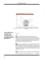
Figure 3.19a, Using equation editor to generate one cycle of sine wave ......................................................................... 51
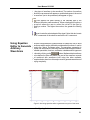
Figure 3.19b, Using equation editor to generate one cycle of sine wave with a higher amplitude .................................. 52
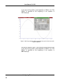
Figure 3.19c, Using equation editor to generate five cycles of sine wave ....................................................................... 53
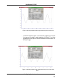
Figure 3.19d, Using equation editor to generate five cycles of sine cubed wave............................................................. 53
Figure 3.19e, Using equation editor to add second harmonic distortion to sine wave ..................................................... 54
Figure 3.19f, Using equation editor to generate exponentially decaying sine Wave ....................................................... 55
Figure 3.19g, Using equation editor to build amplitude modulated signal with upper and lower sidebands ................... 55
Figure 3.20, opening or saving waveforms...................................................................................................................... 56
Figure 3.21, Importing data from other applications using .csv file format ..................................................................... 57
Figure 3.22, Sequence Table Download Format.............................................................................................................. 62
Figure 3.23, Selecting number of sequences to be used................................................................................................... 63
Figure 3.24, Selecting the active sequence and entering sequences................................................................................. 64
Figure 3.25, Selecting Sequence output mode ................................................................................................................. 64
Figure 3.26, Squenced Sequences.................................................................................................................................... 69
Figure 3.27, The Sequence Editor.................................................................................................................................... 70
Figure 3.28a, Multi Sequence Table Editor with 3 sequences ......................................................................................... 72
Figure 3.28b, Multi Sequence Table Editor with 7 sequences and repeated sequences................................................... 72
Figure 3.29, Channel to Channel Phase adjustment in WaveWiz.................................................................................... 75
Figure 3.30, Entering SCPI commands direct from WaveWiz ........................................................................................ 77
Table of Figures
This page intentionally left blank
301/302 User Manual
Getting Started
What’s In This
Chapter
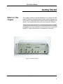
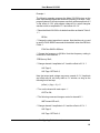
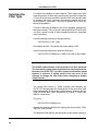
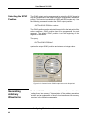
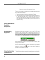
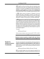
This chapter contains a general description of the Model 301/302
Arbitrary Waveform Generator and an overall functional description of
the instrument. It lists and describes various options available for this
model. It also describes the front panel connectors and indicators.
This manual provides description of all features and options available
with the instruments; however, some items described in the following
paragraphs may not be installed in your instrument. If you purchased
Model 301, ignore all references in this manual to Channel B.
Figure 1-1, Model 301/302
Getting Started
1
301/302 User Manual
Introduction
A detailed functional description is given following the general
description of the features, functions, and options available with the
Model 301/302.
Model 301 is a single-channel Arbitrary Waveform Generator. Model
302 is a dual-channel, Arbitrary Waveform Generator. It is a high
performance waveform generator that combines two separate and
powerful channels in one package.
Each channel has its own waveform generator, as well as, amplitude,
offset, and AM controls. The two channels share common sample
clock source therefore, inter-channel phase relationship can be
controlled tightly.
Both channels generate waveforms from one sample clock source
and start from one trigger source, ensuring that all waveforms are fully
synchronized in terms of frequency and start phase of the output
waveforms. Further control over start phase is provided in cases
where phase offset between the two channels is required.
Model 301/302 is completely digital. There are no analog functions
resident in its hardware circuits. Data has to be downloaded to the
instrument for it to start generating waveforms. The instrument can
generate a few standard functions such as sine wave, triangular wave
and square wave. Each time that a standard function is required, the
instrument has to calculate its coordinates and place them in the
waveform memory. Therefore, every time a standard function is
recalled, minimal time is required for the controller to compute the
function and load its data to the waveform memory.
The frequency accuracy of the output waveform is determined by the
clock reference. The internal reference oscillator provides 1 ppm
accuracy and stability over time and temperature. If higher accuracy
and/or stability are required, The user may connect his own sample
clock generator to a front panel input. Frequency is programmed with
7 digits, so using an external sample clock source is recommended if
you need better resolution, accuracy and stability.
Output amplitude for each channel may be programmed separately
within the range of 20 mV to 10 Vp-p into an open circuit, or 10 mV to
5 V into 50 . Offset is applied directly at the output connector
therefore, it is not attenuated with the output signal. This feature
allows generation of low-level signals with very high offset ratio. For
example, it is possible to program 50 mV amplitude with 2 V offset.
Amplitude and offsets are programmed with 4 digits of resolution.
Besides its normal continuous mode, the Model 301/302 responds to
a variety of trigger sources. The output waveform may be gated,
Getting Started
2
301/302 User Manual
triggered, or may generate a counted burst of waveforms. A built-in
trigger generator, having a programmable period can be used as a
replacement of an external trigger source.
The Model 301/302 generates arbitrary waveforms with 12 bits of
vertical resolution. Any waveform it generates must first be
downloaded to waveform memory.
The arbitrary waveform memory is a bank of 12-bit words. Each word
represents a point on the horizontal waveform scale. Each word has a
horizontal address that can range from 0 to 4,191,280 (16,777,720)
with the 16 Meg option installed) and a vertical address that can
range from -2048 to +2047 (12 bits). Using a high speed clocking
circuit, the digital contents of the arbitrary waveform memory are
extracted and routed to the Digital to Analog Converter (DAC). The
DAC converts the digital data to an analog signal, and the output
amplifier completes the task by amplifying or attenuating the signal at
the output connector.
There is no need to use the complete memory every time an arbitrary
waveform is generated. Waveform memory can be divided into up to
4096 smaller segments and different waveforms can be loaded into
each segment. The various segments may then be loaded into a
sequence table to generate long and complex waveforms. The
sequence table can link up to 4096 segments, while each segment
can loop up to 1 million times. The model 301/302 can store up to 16
different sequence tables, then use these sequences for generating a
sequence of these 16 sequences.
The instrument must be used in conjunction with a host computer. All
of its functions, modes and parameters are fully programmable using
SCPI commands and syntax. There are three ways to program the
Model 301/302, the first being low-level programming of each
individual parameter using SCPI commands. The second alternative
is to use WaveWiz for high-level programming. WaveWiz is a
software package supplied with the 301/302 that simulates a
mechanical front panel. It has all the necessary push buttons, displays
and dials to operate the Model 301/302 in a similar way to using a
bench-top instrument. The third way to program the 301/302 is by
using either the LabVIEW driver.
The Model 301/302 must be programmed to generate waveforms.
Therefore, it is recommended that the user becomes familiar with its
basic features, functions and programming concepts as described in
this and the following chapters.
Options
There is only one option available with the model 301/302. This option
expands the waveform memory from 4 Meg to 16 Meg. The
instrument must be ordered with the 16 Meg option installed, it cannot
Getting Started
3
301/302 User Manual
be retrofitted later.
The 4 Meg option designates the memory size supplied with the
standard Model 301/302. With the standard memory size, 4,191,280
point waveforms can be programmed. The 16 Meg option designate
an instrument supplied with memory expansions. With the 16 Meg
memory expansion, 16,776120 point waveforms can be programmed
for each channel.
Safety
Considerations
The Model 301/302 has been manufactured according to international
safety standards. The instrument meets EN61010, VDE 0411/03.81
and UL 1244 standards for safety of commercial electronic measuring
and test equipment for instruments with an exposed metal chassis
that is directly connected to earth via the chassis power supply cable.
WARNING
Do not remove instrument covers when operating or when
the chassis power cord is connected to the mains.
Any adjustment, maintenance and repair of an opened, powered-on
instrument should be avoided as much as possible, but when
necessary, should be carried out only by a skilled person who is
aware of the hazard involved.
Supplied
Accessories
The instrument is supplied with an Instruction Manual. The manual
includes a disk with WaveWiz for Windows 95/98/NT. A Service
Manual is available upon request.
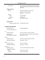
Specifications
Instrument specifications are listed in Appendix A. These
specifications are the performance standards or limits against which
the instrument is tested. Specifications apply under the following
conditions: output terminated into 50Ω after 30 minutes of warm up
time, and within a temperature range of 20oC to 30oC. Specifications
outside this range are degraded by 0.1% per oC.
Functional
Description
A detailed functional description is given in the following paragraphs.
The description is divided into logical groups: input and output
connectors, operating modes, output type, output state, filters,
synchronization, and front panel indicators.
Getting Started
4
301/302 User Manual
Input and Output
Connectors
The Model 301/302 has 6 or 9 BNC connectors on its front panel: one
main output and one auxiliary output per channel, one SYNC output,
one AM input per channel, one trigger input and one sample clock
input.
Main Output Channel A
The channel A output connector outputs fixed (standard) waveforms
to 150 MHz, user (arbitrary) and sequenced waveforms with sampling
clock to 300 MS/s. Output impedance is 50Ω, that is, the cable
connected to this output should be terminated with 50Ω. Output
amplitude accuracy is calibrated when connected to a 50Ω load. The
output amplitude is doubled when the output impedance is above 1
MΩ.
Auxiliary Output Channel A (I)
The Auxiliary output connector outputs exactly the same waveforms
as the Main output connector. The only difference is that the low
output has fixed amplitude of 1 Vp-p into 50Ω
Main Output Channel B
The Channel B output connector outputs fixed (standard) waveforms
to 150 MHz, user (arbitrary) and sequenced waveforms with sampling
clock to 300 MS/s. Output impedance is 50Ω, that is, the cable
connected to this output should be terminated with 50Ω. Output
amplitude accuracy is calibrated when connected to a 50Ω load. The
output amplitude is doubled when the output impedance is above 1
MΩ.
Auxiliary Output Channel B (Q)
The Channel B Auxiliary output connector outputs exactly the same
waveforms as the Main output connector. The only difference is that
the low output has fixed amplitude of 1 Vp-p into 50Ω
SYNC Output
The SYNC output generates a single TTL pulse for synchronizing
other instruments (i.e., an oscilloscope) to the output waveform. The
SYNC signal always appears at a fixed point relative to the waveform.
The location of the signal along the waveform is programmable.
Trigger Input
In general, the trigger input accepts signals that stimulate the output
waveforms. The trigger input is inactive when the generator is in
Getting Started
5
301/302 User Manual
continuous operating mode. When placed in trigger, gated or burst
mode, the trigger input is made active and waits for the right condition
to trigger the instrument. In trigger and burst modes, the trigger input
is edge sensitive, i.e., it senses transitions from high to low or from
low to high to trigger the Model 301/302. The direction of the transition
is programmable. In gated mode, the trigger input is level sensitive,
i.e., the Model 301/302 is gated when the logic level is high and idle
when the level is logic low. Trigger level for this input is
programmable.
The trigger input is common to both channels. Therefore, if the model
301/302 is placed in trigger mode, both channels share the same
mode and the trigger input causes both channels to start generating
waveforms at the same time.
Phase relationship between channels is tightly controlled in trigger
mode. You should expect that both channels will start generating
waveforms with exactly the same start phase. Further control over
phase offset between channels is also provided. Applying a phase
offset between the channels is described later in this manual.
AM Input –
Channel A
The channel A AM input accepts signals that amplitude modulate the
channel A signal. The Channel A AM input becomes active only when
the AM function is selected.
AM Input –
Channel B
The channel B AM input accepts signals that amplitude modulate the
channel B signal. The Channel B AM input becomes active only when
the AM function is selected.
Sample Clock Input
The external clock input is available for those applications requiring
synchronization to one sample clock source. Normally, this input is
disabled. When enabled, the clock at this input replaces the internal
clock generator and the 301/302 generates waveforms with the
sample clock at the Sample Clock input.
Operating Modes
The 301/302 can be programmed to operate in one of four operating
modes: continuous, triggered, gated and counted burst. These modes
are described below.
As was discussed above, both channels are placed simultaneously in
triggered mode. All channels will start generating waveforms when a
valid trigger signal is received at the trigger input. Both waveforms will
start and complete at exactly the same instance.
Getting Started
6
301/302 User Manual
Continuous Mode
In normal continuous mode, the selected waveform is generated
continuously at the selected frequency, amplitude and offset.
Triggered Mode
In triggered mode, the Model 301/302 circuits are armed to generate
one output waveform. The trigger circuit is sensitive to transitions at
the trigger input. Select between positive or negative transitions to
trigger the instrument. You may also program the trigger level to the
desired threshold level. When triggered, the generator outputs one
waveform cycle and remains idle at the last point of the waveform.
The Model 301/302 can be armed to receive a trigger signal from a
front panel connector or from a GPIB command or from an internal,
programmable trigger generator.
The trigger signal, whether it comes from the front panel or from the
GPIB interface, has to pass through some electrical circuits. These
circuits cause a small delay known as system delay. System delay
cannot be eliminated completely. It is, however, minimized in the
Model 301/302 to approximately 100 ns maximum. System delay is a
factor that must be considered when applying a trigger signal. It
defines how long it will take from a valid trigger edge to the moment
that the output reacts.
Burst Mode
The burst mode is an extension of the triggered mode where the
Model 301/302 can be programmed to output a pre-determined
number of waveforms. The source to trigger the counted burst cycle
can be selected from a front panel connector, GPIB trigger or from the
built-in trigger generator.
Gated Mode
In gated mode, the Model 301/302 circuits are armed to generate
output waveforms as long as a gating signal is present. Unlike the
triggered mode, the gated mode is level sensitive. When the gating
signal goes low, the waveform at the output connector is first
completed and the output goes to an idle state. The idle amplitude
level, after the gating signal goes low, is the last point on the
waveform.
Output Type
The Model 301/302 can output three types of waveforms: standard
(Fixed), arbitrary (User) and sequenced waveforms. Different
waveform types may be assigned to each channel. Description of the
various waveform types that the Model 301/302 can generate is given
below.
Getting Started
7
301/302 User Manual
Standard (Fixed)
Waveforms
The Model 301/302 generates waveforms from a memory that has to
be loaded before the instrument can generate waveforms. There are
a number of memory options that are available with the instrument.
Memory option must be specified at the time of purchase. Field
upgrade of memory options is not available. On power up, the
waveform memory has no specific data. The sine waveform, being the
default waveform on power on, is computed and loaded to the
waveform memory as part of the reset procedure. From this moment
on, every time that another standard waveform is selected, it is being
computed and loaded to the waveform memory.
Waveforms are written from the same start address. Therefore, every
time that a new waveform is selected, there is some minimal time for
the processor to compute and download the data to the memory.
The Model 301/302 can be programmed to output one of nine
standard waveform shapes: sine, triangle, square, pulse/ramp,
sine(x)/x pulse, gaussian pulse, rising/decaying exponential pulse,
noise and dc. There are some parameters associated with each
waveform, which modify the shape of the waveform to better suit your
needs. For example, different start phase for the sine waveform can
be programmed for each channel to create phase offsets between the
two output channels.
Arbitrary (User)
Waveforms
The arbitrary waveform memory is capable of storing one or more
user-defined waveforms. As was discussed before, and unless
ordered differently, the Model 301/302 is supplied with 4 Meg memory
banks with channels 1 and 2. With the 16 Meg option, there are up to
16 Meg points that can be allocated to one single waveform. On the
other hand, there is no need to use the entire memory for only one
waveform. The memory can be divided into smaller segments and
loaded with different waveforms. The instrument can be programmed
to output one segment at a time.
Loading data to arbitrary waveform memory can be a time-consuming
task, especially if all 16 Meg points are loaded in one shot. The Model
301/302 utilizes a DMA concept that speeds data transfer from host
computer to the instrument. In this mode, the memory bank is
disconnected from the CPU circuit and re-routed to the GPIB bus for
direct memory accessing by the host computer.
There are two separate memory banks for each channel that can be
loaded with different waveforms. Channels are not limited by the
number of segments and by the shape of the waveforms.
Getting Started
8
301/302 User Manual
Sequenced
Waveforms
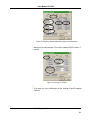
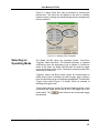
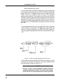
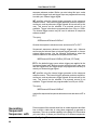
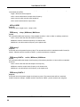
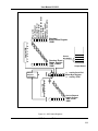
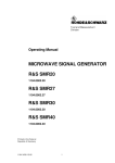
The sequence generator is a very powerful tool that lets you link and
loop segments in any way you desire. As a simple example of a
sequenced waveform, look at Figures 1-1a through 1-1c. The
waveforms shown in these figures were placed in memory segments
1, 2 and 3, respectively. The sequence generator takes these three
waveforms links and loops them in a predefined order to generate the
waveform shown in Figure 1-1d.
The sequence circuit is useful for generating long waveforms with
repeated sections. The repeated waveform has to be programmed
once and the repeater loops on this segment as many times as
selected. When in sequenced mode, there is no loss of time between
linked or looped segments.
The Model 301/302 can store up to 16 different sequences, then use
these sequences in a macro sequence that can sequence all 16
sequences. The sequence generator, as well as, the macro sequence
generator is common to both channels.
Sequence tables must be loaded to the generator before sequenced
waveforms can be generated. The data for the sequence table is first
prepared on external platforms, then downloaded to the generator.
Figure 1-5 shows an example how to define a sequence using
WaveWiz.
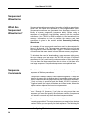
Figure 1.1a , Segment 1 – Sin (x)/x Waveform
Getting Started
9
301/302 User Manual
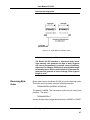
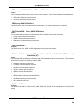
Figure 1.1b. Segment 2 – Sine Waveform
Figure 1.1c Segment 3 – Pulse Waveform
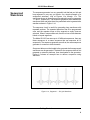
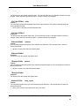
The following sequence was made of segment 2 repeated twice,
segment 1 repeated four times, and segment 3 repeated two times.
Figure 1.1d Sequenced Waveforms
Getting Started
10
301/302 User Manual
Output State
The main outputs can be turned on or off. The internal circuit is
disconnected from the output connector by a mechanical switch
(relay). This feature is useful for connecting the main outputs to an
analog bus. For safety reasons, when power is first applied to the
chassis, the main output is always off.
Filters
Ten filters are built into the Model 301/302, five for each channel.
These filters are available for use in various applications such as the
creation of high frequency sine waves and removing the staircase
effect from waveforms that are generated with high frequency clock
rates.
Front Panel
Indicators
There are five LEDs on the front panel. The POWER LED (Red)
illuminates at power-up and remains on until the Model 301/302 has
been turned off.
The ACCESS LED (Amber) illuminates each time a command has
been received by the Model 301/302. This light remains on during
DMA data transfer.
The REMOTE light turns on the first time the GPIB remote enable line
is true. GTL (go to local) command or power down turn this light off.
When the output state is on, the OUTPUT LED (Green) light
illuminates. There are two LEDs, one for each channel. Note that the
LEDs are part of the Main output. There is no ON indication for the
Auxiliary outputs.
Programming The
Model 301/302
The Model 301/302 has no controls on its front panel. Instrument
functions, parameters, and modes can only be accessed through
GPIB or RS232 commands. There are a number of ways to “talk” to
the instrument. They all require that an appropriate software driver be
installed in the host computer. The rest is a matter of practice and
knowledge of the language in use. There are other system
considerations like address selection that have to be settled before
programming the instrument. These topics are discussed in later
chapters.
Low level programming of the Model 301/302 is accomplished using
SCPI (Standard Commands for Programmable Instruments)
language. Programming aspects are covered in Chapters 3 and 4.
Supplied with the 301/2 is a PC software package called WaveWiz.
This provides a user interface with a familiar windows interface which
allows the user to interact with and control the 301/2 directly. Details
of how to use WaveWiz are supplied in the following pages.
Getting Started
11
User Manual 301/302
CONFIGURING The INSTRUMENT
Installation
Overview
This chapter contains information and instructions necessary to
prepare the Model 301/302 for operation. Details are provided for
initial inspection, grounding requirements, repackaging instructions for
storage or shipment, address selection and installation information.
Unpacking and
Initial Inspection
Unpacking and handling of the generator requires normal precautions
and procedures applicable to handling of sensitive electronic
equipment. The contents of all shipping containers should be checked
for included accessories and certified against the packing slip to
determine that the shipment is complete.
Safety
Precautions
The following safety precautions should be observed before using this
product and associated computer. Although some instruments and
accessories would normally be used with non-hazardous voltages,
there are situations where hazardous conditions may be present.
This product is intended for use by qualified persons who recognize
shock hazards and are familiar with the safety precautions required to
avoid possible injury. Read the operating information carefully before
using the product.
WARNING
For maximum safety, do not touch the product, test cables, or any
other instrument parts while power is applied to the circuit under
test. ALWAYS remove power from the entire test system before
connecting cables or jumpers, installing or removing cards from
the computer, or making internal changes such as changing the
GPIB address.
Do not touch any object that could provide a current path to the
common side of the circuit under test or power line (earth) ground.
Always keep your hands dry while handling the instrument.
Exercise extreme caution when a shock hazard is present. Lethal
voltage may be present on cables, connector jacks, or test fixtures.
The American National Standard Institute (ANSI) states that a shock
hazard exists when voltage levels greater than 30V RMS, 42.4V peak,
Configuring The Instrument
12
User Manual 301/302
or 60VDC are present. Before operating an instrument, make sure the
line cord is connected to a properly grounded power receptacle.
Inspect the connecting cables and test leads for possible wear,
cracks, or breaks before each use.
For maximum safety, do not touch the product, test cables or any
other of the instrument parts while power is applied to the circuit under
test. ALWAYS remove power from the entire test system before
connecting cables or jumpers, installing or removing cards from the
computer or making internal changes, such as changing card address.
Do not touch any object that could provide a current path to the
common side of the circuit under test or power line (earth) ground.
Always keep dry hands while handling the instrument.
When using test fixtures, keep the lid closed while power is applied to
the device under test. Carefully read the “Safety Precautions”
instructions that are supplied with your test fixtures.
Before performing any maintenance, disconnect the line cord and all
test cables. Only qualified service personnel should perform
maintenance.
If you have no past experience in computer servicing, we strongly
recommend that installation and initial tests on the instrument be done
by your computer dealer or by the factory itself
Performance
Checks
The instrument has been inspected for mechanical and electrical
performance before shipment from the factory. It is free of physical
defects and in perfect electrical order.
Power
Requirements
The function generator may be operated from any one of the following
sources: a. 103.5 to 126.5 Volts (115 Volts, NOMINAL) b. 207 to 253
Volts (230 Volts, NOMINAL).
The instrument operates over the power mains frequency range of 48
to 63Hz. Always verify that the operating power mains voltage is the
same as that specified on the rear panel voltage selector switch.
The Model 301/302 should be operated from a power source with its
neutral at or near ground (earth potential). The instrument is not
intended for operation from two phases of a multi-phase ac system or
across the legs of a single-phase, three-wire ac power system. Crest
factor (ratio of peak voltage to rms.) should be typically within the
range of 1.3 to 1.6 at 10% of the nominal rms. mains voltage.
Configuring the Instrument
13
User Manual 301/302
Grounding
Requirements
To ensure the safety of operating personnel, the U.S. O.S.H.A.
(Occupational Safety and Health) requirement and good engineering
practice mandate that the instrument panel and enclosure be "earth"
grounded. The long offset pin on the male end of the power cable
carries the ground wire to the long pin of the Euro connector (DIN
standard) receptacle on the rear panel of the instrument.
To preserve the safety protection feature when operating the
instrument from a two-contact outlet, use a three-prong to two-prong
adapter and connect the green lead on the adapter to an "earth"
ground.
WARNING
Do not attempt to float the output from ground as it may damage
the Model 301/302 and your equipment.
CAUTION
To avoid operator shock hazard do not exceed the power mains
voltage frequency rating which limits the leakage current
between case and power mains. Never expose the instrument to
rain, excessive moisture, or condensation.
Long Term
Storage or
Repackaging For
Shipment
If the instrument is to be stored for a long period of time or shipped
immediately, proceed as directed below. If you have any questions,
contact your local Wavetek-Datron Representative or the WavetekDatron Customer Service Department.
1.
Repack the instrument using the wrappings, packing material
and accessories originally shipped with the unit. If the original
container is not available, purchase replacement materials.
2.
Be sure the carton is well sealed with strong tape or metal
straps.
3.
Mark the carton with the model and serial number. If it is to be
shipped, show sending and return address on two sides of the
box.
NOTE
If the instrument is to be shipped to Wavetek-Datron for
calibration or repair, attach a tag to the instrument identifying
the owner. Note the problem, symptoms, and service or repair
Configuring The Instrument
14
User Manual 301/302
desired. Record the model and serial number of the instrument.
Show the work authorization order as well as the date and
method of shipment. ALWAYS OBTAIN A RETURN
AUTHORIZATION NUMBER FROM THE FACTORY BEFORE
SHIPPING THE INSTRUMENT TO Wavetek-Datron.
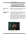
Preparation For
Use
Preparation for use includes removing the instrument from the
container box, selecting the required logical address and connecting
the instrument to the power line and to a host computer.
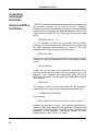
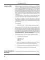
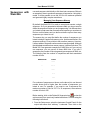
Logical Address
Selection
The GPIB Resource Manager identifies modules in the system by the
module’s address. GPIB logical addresses can range from 0 to 31,
however, addresses 1 to 31 only are reserved for GPIB instruments.
Logical address 0 is reserved for the GPIB controller.
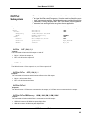
To change the logical address, open the top cover and use the 8position DIP switch accessible from the top side of the generator near
the rear end of the case (switch S1). Figure 2-1 shows the location of
the logical address switch. The switches are marked with numbers 1
to 8. The Model 301/302 uses binary values (20 to 27) to set the
logical address using the active low address switch. A switch is active
when its arm is placed in the ON position. Wavetek-Datron ships the
Model 301/302 with logical address 2.
Figure 2.1 Setting Logical Address
Configuring the Instrument
15
User Manual 301/302
Installation
The instrument is fully solid state and dissipates only a small amount
of power. No special cooling is required. However, the instrument
should not be operated where the ambient temperature exceeds 40°C,
when the relative humidity exceeds 80% or condensation appears
anywhere on the instrument.
Avoid operating the instrument close to strong magnetic fields, which
may be found near high power equipment such as motors, pumps,
solenoids or high power cables. Use care when rack mounting to
locate the instrument away from sources of excessive heat or
magnetic fields. Always leave 4 cm (1.5 inches) of ventilation space
on all sides of the instrument.
Bench Operation
The Model 301/302 is shipped with plastic feet, tilt stand in place and
ready for use as a bench or portable instrument
Rack Mounting
The instrument may be rack mounted in a standard 19 inch rack. Rack
mounting ears are part of the 302 case. Telescopic rack mounting
slides are also available.
Configuring The Instrument
16
User Manual 301/302
USING The INSTRUMENT.
Overview
This chapter contains information about how to operate the Model
301/302. The Model 301/302 must be programmed to turn on
functions, change parameters and configure various operating
modes. The Model 301/302 is supplied with WaveWiz, a PC based
software package with a graphical user interface to allow users to
program all of the functions directly. LabView drivers and a set of
SCPI commands are available for more experienced programmers.
SCPI (standard commands for programmable instruments)
commands for the Model 301/302 are listed in Table 4-1. This manual
provides information on low-level programming using SCPI
commands and using WaveWiz to control the same functions.
The following paragraphs describe the various modes of operation
and give examples of how to program the Model 301/302. The
manual is organized by instrument function and instructions are given
in each paragraph on how to use the function from both SCPI and
WaveWiz.
Inter-Channel
Dependency
The Model 302 has two output channels. Although this is a twochannel instrument, most of the commands that set parameters and
functions are common for both channels. For example, sample clock
and trigger modes can not be set separately for each channel. On the
other hand, you may program each channel to have different function
shape, amplitude and offset. Table 3-1 lists the function and
parameters and their related Inter-channel dependency.
Output
Termination
During use, output connectors must be properly terminated to
minimize signal reflection or power loss due to impedance mismatch.
Proper termination is also required for an accurate amplitude level at
the main output connector. Use 50Ω cables and terminate the main
and SYNC cables with terminating resistors. Always place the 50Ω
termination at the far end of the cables.
Input / Output
Protection
The Model 301/302 provides protection for internal circuitry connected
to input and output connectors. Refer to the specifications in Appendix
A to determine the level of protection associated with each input or
output connector.
Configuring the Instrument
17
User Manual 301/302
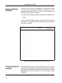
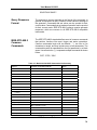
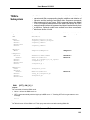
Power On/Reset
Defaults
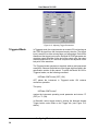
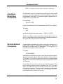
At Power On or as a result of a software reset, the instrument defaults
to some factory pre-selected conditions. A complete list of all
parameters, their default values, as well as their maximum and
minimum values is given in Chapter 4.
Use the following command to place the instrument in its default state:
RESet;
Using the IEEE-STD-488.2 common command *RST will have the
same result. The table below shows the instrument settings after this
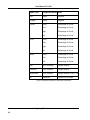
command is executed.
Function / Parameter
Default
Inter-Channel
Dependency
Output State:
Off
Separate
Operating Mode:
Continuous
Common
SYNC State:
Off
Common
SYNC Out Position:
Wave Start
Common
Output Function:
Standard
Separate
Output Function Shape:
Sine
Separate
Standard Wave Frequency:
1 MHz
Common
User Wave Sample Clock:
10 MHz
Common
Amplitude:
2V
Separate
Offset:
0V
Separate
Filter State:
Off
Separate
Filter Type:
Auto
Separate
Trigger Slope:
Positive
Common
Trigger Level:
1.6 V
Common
Internal Trigger Period:
100 µs
Common
AM State:
Off
Separate
DMA State:
Off
Separate
Figure 3.1 Default Conditions After Power On or After *RST
Programming the
301/302
When writing low level code to operate the Model 301/302, follow the
instructions in this chapter to understand the meaning and response
that each command generates. Examples contained in the following
paragraphs show basic techniques of how to program output
waveforms.
Configuring The Instrument
18
User Manual 301/302
Example 1
The following example programs the Model 301/302 to turn on the
main outputs and program the waveform frequency to 20 MHz. Then,
program channel A to output square waveform with an amplitude of 2
V and offset of 0.5V, and program channel B to output triangular
waveform with an amplitude of 1 V and offset of 0.5 V.
/* Reset the Model 301/302 to its default condition as listed in Table 31. */
:RESet;
/* Change the output waveform to square. Note that there is no need
to use the FUNC:MODE command as the default value after RESet is
FIXed. */
:FUNCtion:SHAPe SQUare;
/* Change the frequency to 20 MHz. Note that frequency setting is
common for both channels. */
:FREQuency 20e6;
/* Change channel A amplitude to 2 V and the offset to 0.5 V. */
:VOLTage 2;
:VOLTage: OFFSet 0.5;
Note that output peak voltage may never exceed ±2.5 V. Amplitude
and offset may be set freely within a 5 V window, as long as the
following limits are kept:
| offset | + (Vp-p ÷ 2) ≤ 5
/* Turn on the channel A main output. */
:OUTPut ON;
/* The following command changes control to channel B. */
:INSTrument:SELect 2;
/* Change channel 2 amplitude to 2 V and the offset to 0.5 V. */
:VOLTage 2;
:VOLTage: OFFSet 0.5;
Configuring the Instrument
19
User Manual 301/302
/* Turn on the channel 2 main output. */
:OUTPut ON;
If the above commands are executed correctly, a square waveform
will be seen on your oscilloscope at the channel A and B outputs
connector.
Controlling the
301/2 Using
WaveWiz
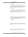
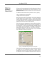
To repeat the above sequence of commands using WaveWiz, perform
the following sequence of steps having started WaveWiz running.
Open the Instrument Front Panel by clicking on the
button
Reset the Model 301/302 to its default condition as listed in Table 3-1.
By clicking on the *RST button on the System tab
Figure 3.2 Reset button on the System Tab
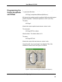
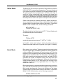
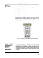
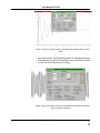
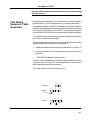
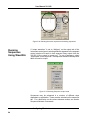
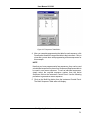
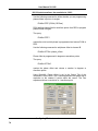
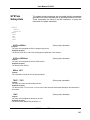
Select the Standard tab, and on both channel A and B, change the
output waveform to square; change the frequency to 20 MHz;
change the output voltage to 2.0 V; and the offset to 0.5V by
clicking the relevant buttons and entering data into each relevant
data entry box (see Figure3.3 below). The command is executed
either by clicking OK, which will close the instrument control panel,
or by hitting the tab key on the PC keyboard, which will leave the
instrument control panel open for further control changes.
Configuring The Instrument
20
User Manual 301/302
Figure 3-3 Adjusting Standard Waveform types and Parameters
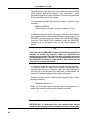
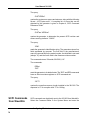
Select the Output tab, and turn on each channel output by selecting
Channel on for each channel. Turn on the channel SYNC output, if
required.
Figure 3-4 Turning on Outputs
If the above commands are executed correctly, a square waveform
will be seen on your oscilloscope at the channel A and B outputs
connector.
Configuring the Instrument
21
User Manual 301/302
Controlling
Instrument
Functions
Using the APPLy
Command
The APPLy command provides a high level method of programming
the generator. Selection can be made for function, frequency,
amplitude, offset and other parameters, which are associated with the
applied function. For example, the following statement outputs a 2 Vpp square wave at 1 MHz with a 0 V offset and 10% duty cycle using
APPLy:
APPL:SQU 1E6, 2, 0, 10
It is not necessary to enter every parameter with the APPLy
command. If only the frequency and offset need to be changed, omit
the other parameters while keeping the commas. The other
parameters will be set to the power-up default values:
APPL:SQU 10E6,,1
Alternatively, if just the first parameters need to be changed, omit the
commas. The other parameters will be set to the power-up default
values:
APPL:SQU 4e6,2
Queries can also be made on all parameters associated with a
standard function using the APPL: <function_shape>? query. For
example, if the generator was programmed using the above
APPLy:SQU command, query the square wave parameters using the
following query:
APPL:SQU?
The generator returns a string that contains all the parameters
associated with the square function similar to the following string:
"1.000000e+6,2.000,0.000,50"
The command:
APPLy:SINusoid {<frequency>,<amplitude>,<offset>,<phase>}
programs the generator to output a sine waveform with frequency,
amplitude, offset, start phase and power parameters. Parameters are
not optional if the above APPLy command is used. Include all other
parameters in the command. The default settings for these
parameters are: 1 MHz, 2 Vp-p, 0 V, 0 and 1.
Configuring The Instrument
22
User Manual 301/302
The command:
APPLy:TRIangle {<frequency>,<amplitude>,<offset>,<phase>}
programs the generator to output a triangle waveform with frequency,
amplitude, offset, start phase, and power parameters. The default
settings for these parameters are: 1 MHz, 2 Vp-p, 0 V, 0 and 1.
The command:
APPLy:SQUare {<frequency>,<amplitude>,<offset>,<duty_cycle>}
programs the generator to output a square waveform with frequency,
amplitude, offset and duty cycle parameters. The default settings for
these parameters are: 1 MHz, 2 Vp-p, 0 V, and 50%.
The command:
APPLy:PULSe{<frequency>,<amplitude>,<offset>,
<delay>,<high_time>,<rise_time>,<fall_time>}
programs the generator to output a pulse waveform with frequency,
amplitude, offset, and delay, rise time, high time and fall time
parameters. The default settings for these functions are: 1 MHz, 2 Vpp, 0 V, 0%, 10%, 10% and 10%. Percentage in this instance refers to
percentage of period of the waveform.
The command:
APPLy:RAMP {<frequency>,<amplitude>,<offset>,
<delay>, <rise_time>,<fall_time>}
programs the generator to output a ramp waveform with frequency,
amplitude, offset, delay, rise time, and fall time parameters. The
default settings for these functions are: 1 MHz, 2 Vp-p, 0 V, 0%, 60%
and 30%.
The command:
APPLy:SINC {<frequency>,<amplitude>,<offset>,
<number_cycles>}
programs the generator to output a sine(x)/x waveform with frequency,
amplitude, offset, and number of cycles parameters. The default
settings for these functions are: 1 MHz, 2 Vp-p, 0 V and 10.
The command:
APPLy:EXPonential <frequency>,<amplitude>,<offset>,
Configuring the Instrument
23
User Manual 301/302
<exponent>}
programs the generator to output an exponential waveform with
frequency, amplitude, offset, and exponent parameters. The default
settings for these functions are: 1 MHz, 2 Vp-p, 0 V and -10.
The command:
APPLy:GAUSsian {<frequency>,<amplitude>,<offset>,
<exponent>}
programs the generator to output a gaussian waveform with
frequency, amplitude, offset, and exponent parameters. The default
settings for these functions are: 1 MHz, 2 Vp-p, 0 V and 10.
The command:
APPLy:DC {<percent_amplitude>}
Programs the generator to output a DC level. The DC level is set as a
percent of programmed amplitude. The default setting for this function
is 100%.
The command:
APPLy:USER
{<segment_number>,<sampling_clock>,<amplitude>,<offset>}
programs the generator to output an arbitrary waveform. The specified
segment number must be loaded with an arbitrary waveform before
the generator can execute this command successfully. This command
lets you specify segment number, sampling clock rate, amplitude and
offset. The default settings for these parameters are: 1, 1 MHz, 2 Vp-p
and 0 V.
The query:
APPLy:<function_shape>?
queries parameters associated with the specified function shape.
Returns a string of values depending on the parameters that are
available for the selected function shape.
The query:
APPLy?
queries parameters associated with the currently selected function
shape and returns a string of values depending on the parameters
available for the selected function shape. For example, if the
Configuring The Instrument
24
User Manual 301/302
generator is programmed to output a sine waveform, the APPL?
Command returns: "1e+6, 2, 0 , 0.
Example 2
The following example programs the Model 301/302 using the APPLy
command. This example turns on the main output, generates a square
waveform, programs frequency to 2 MHz, programs amplitude to 1 V
and offset to 1 V. It also changes the square wave duty cycle
parameter to 25%.
/* Reset the Model 301/302 to its default condition as listed in Table 31. */
:RESet;
/* Change the output waveform to square, frequency to 2 MHz,
amplitude to 1 V, offset to 1 V and duty cycle to 25%. Note that there
is no need to use the FUNC:MODE command because the default
value after RESet is FIXed. */
:APPLy:SQUare 2e6,1,1,25
/* Turn the main output on. */
:OUTPut ON
/*Turn the SYNC output on, if required. */
:OUTPut:SYNC ON
If the above commands are executed correctly, a square waveform
will be seen on your oscilloscope.
Selecting the
Active Channel
On power up, the instrument defaults to channel A. That means that
each command sent to the generator affects channel A parameters. If
you want to send commands to the other channel, you must switch the
input to the other channel. Proceeding channel selection, all
commands will affect the selected channel only. Use the following
command to select the channel you want to program:
INSTrument:SELect {1 | 2}
When “1” is selected, commands will control parameters that are
unique for the channel A output. Selecting “2”, modifies the control to
channel B parameter. The default option is “1”. Parameters that are
common to both channels may be programmed from either path.
Configuring the Instrument
25
User Manual 301/302
The query:
INSTrument:SELect?
Queries the active channel and returns 1 or 2.
The Control Panel from WaveWiz is shown in Figure 3-5
demonstrates high-level implementation of channel control.
Figure 3.5 Select active channel by clicking on Chan A or B
Enabling the Main
Outputs
301/302 waveforms are generated using data points that are
downloaded to a waveform memory. Using the sample clock
generator, the data is clocked to the digital to analog converter (DAC)
which, in turn, generates the waveform shape that was downloaded to
the arbitrary waveform memory.
The DAC itself can not be connected directly to the main output
because it does not have sufficient drive capabilities, nor does it have
the amplitude and offset control, which is required at the output
connector. To overcome this problem, a high-power output amplifier
circuit is installed directly after the DAC. The amplifier circuit includes
gain, offset, attenuation and stand-by control. The output amplifier is
the circuit that connects to the output connector.
The Model 301/302 also has low-level, auxiliary output connectors.
The low-level outputs are connected directly from the DAC through a
buffer amplifier. Amplitude from these connectors is fixed at 1 Vp-p
into 50Ω.
The auxiliary outputs are used in applications where signal purity and
high signal to noise ratio are crucial. The signal at the output of the
DAC circuit predominantly has these signal qualities. To minimize
damage that may be caused by external misuse of this output, the
signal from the DAC is buffered before it is applied to the low-level
output connector. Waveforms from the Main and Auxiliary outputs are
available at the same time.
For safety reasons, main output default setting is OFF. Disable or
enable the main output using the following command:
OUTPut {OFF | ON}
Configuring The Instrument
26
User Manual 301/302
When the main output state is programmed to ON, the output
connector is connected to the output amplifier through a 50Ω resistor
and an LED near the output connector illuminates. In the OFF
position, the output connector is disconnected from the output
amplifier by means of a mechanical relay. Ensure that voltage is not
applied to the main output connector when the Model 301/302 output
state is programmed to ON.
The query:
OUTPut?
queries the state of the main output and returns "0" (OFF) or "1" (ON).
Figure 3.6 Below shows how the Instrument control panel in WaveWiz
can be used to enable the main outputs. Checking the relevant box
will toggle each output on or off.
Selecting an
Output Type
There are three main types of waveforms that the model 301/302 can
produce: Standard (fixed), Arbitrary (user) and Sequenced waveforms.
Standard waveforms are computed from formulas that are built into
the program. The instrument can output arbitrary and sequenced
waveforms only after waveform data has been downloaded into its
memory.
Use the following command to select the output function type:
FUNCtion:MODE {FIXed | USER | SEQuence}
When “FIXed” is selected, the generator outputs the standard
waveform currently selected by the FUNC:SHAP command. When
“USER” is selected, the generator outputs the arbitrary waveform
currently selected by the TRAC:SEL command. When “SEQuence” is
selected, the generator outputs the sequence that is programmed
using the SEQ:DEF command. The query:
FUNCtion:MODE?
Queries the output function type and returns FIX, USER or SEQ.
Figure 3.6 Below shows how the Instrument control panel in WaveWiz
can be used select the waveform type..
Configuring the Instrument
27
User Manual 301/302
Figure 3.6 Output Control with a WaveWiz Panel.
Selecting a
Standard
Function Shape
Standard (fixed) waveforms are built into the instrument’s program.
Nine standard function shapes are available: Sine, Triangle, Square,
Pulse, Ramp, Sinc, Exponential decaying pulse, Gaussian pulse, and
DC. Every time a standard function is selected the coordinates for this
function are re-computed and placed in the waveform memory.
Therefore, there is a minimal delay after you select the function until
the output starts generating the waveform.
Use the following command to select a standard output function:
FUNCtion:SHAPe {SINusoid | TRIangle | SQUare PULSe |
RAMP | SINC | GAUS | EXP | DC}
The selected waveform is generated using the previously selected
frequency, amplitude, offset, and other relevant settings. The standard
waveform is available at the output connector only after the
FUNC:MODE:FIX command is selected.
The query:
FUNCtion:SHAPe?
queries the standard function shape and returns either SIN, TRI or
Configuring The Instrument
28
User Manual 301/302
SQU.,
The number of points used to define each Standard Waveform is the
same. Thus, some parameters may not have any effect on the
waveform because too few points are available to generate the
waveform. The number of points for each standard waveform at
various frequencies is given below.
The number of points used for generating standard waveforms at
various frequencies is computed as follows:
Frequency ≤ 292.9687 KHz, Points = 1024
Frequency > 292.9687 KHz, Points = N where
N = 8⋅2 ×
300
INT
FREQ
INT log 2
8
Using WaveWiz, the standard Waveforms are selected using the
Standard tab in the Instrument Control Panel. Click on the relevant
diamond shaped button next to the waveform type required.
Figure 3.7, Standard Waveform Selection Panel
Each signal type has a number of variable parameters associated
with it other than frequency and amplitude. Controls for the
parameters are accessed by clicking the box to the right of the
standard signal selection. Parameters which may be changed and
their units are as follows:
Configuring the Instrument
29
User Manual 301/302
Signal Type
Variable Parameter Units
Sine
Phase
Degrees
Triangle
Phase
Degrees
Square
Delay
Percentage of Period
Rise
Percentage of Period
High
Percentage of Period
Fall
Percentage of Period
Delay
Percentage of Period
Rise
Percentage of Period
High
Percentage of Period
Fall
Percentage of Period
Delay
Percentage of Period
Rise
Percentage of Period
Fall
Percentage of Period
Sinc
Zero Crossings
Integer Number
Gaussian
Time Constant
Integer Number
Exponential
Time Constant
Integer Number (+ve or –ve)
DC
Amplitude
Percent of Full Scale
Pulse
Ramp
Figure3.8 Standard Waveform Adjustable Parameters
Configuring The Instrument
30
User Manual 301/302
Figure 3.9 Adjusting Parameters of standard signals
Changing the
Frequency and
Sample Clock
The user should be careful not to confuse waveform frequency with
sample clock frequency. The waveform frequency parameter is valid
for standard waveforms only and controls waveform frequency at the
output connector. On the other hand, the sample clock frequency
parameter is valid for arbitrary waveforms only and defines the
frequency of which the generator clocks data points.
Standard waveform frequency is measured in units of Hz. Arbitrary
waveform sample clock frequency is measured in units of Sa/s
(samples per second). The frequency of a given arbitrary waveform at
the output connector is dependant on sample clock frequency, the
number of data points, and the specifics of the waveform defined
Use the following command to change the frequency for standard
waveforms:
FREQuency {<frequency> | MINimum | MAXimum}
MIN selects the lowest frequency allowed for the currently active
function. MAX selects the highest frequency allowed for the currently
active function. The default frequency setting is 1 MHz for all
parameters.
The query:
Configuring the Instrument
31
User Manual 301/302
FREQuency?
queries the frequency setting for the standard function currently active
and returns a value in hertz.
The command:
FREQuency:RASTer {<frequency> | MINimum |MAXimum}
Sets the sample clock frequency for the user and sequenced mode
parameters. MIN selects the lowest frequency allowed for the currently
active segment or sequence. MAX selects the highest frequency
allowed for the currently active segment or sequence. The default
sample clock frequency setting is 10 MHz for all.
The query:
FREQuency:RASTer?
queries the sample clock frequency setting for the arbitrary segment
or sequence currently active and returns a value in Hertz.
Using WaveWiz, frequency of standard signals is also set in the
Standard tab in the Instrument Control Panel. See Figure 3.9 above.
Selecting the
External SCLK
In cases where synchronization to other instrument in the system is
needed, one may use the front panel SCLK input for replacing the
internal sample clock generators. Use the following command to
select the external SCLK input:
FREQuency:RASTer:SOURce {INTernal | EXTernal}
INT is the default state of the instrument after power up. Select EXT to
activate the front panel SCLK input.
The query:
FREQuency:RASTer:SOURce?
queries the sample clock source and returns INT or EXT.
WaveWiz has no specific command control for this function; it is set by
sending a SCPI command directly from the system menu in the
Instrument Front Panel. (For a more detailed description see later in
this chapter).
Configuring The Instrument
32
User Manual 301/302
Programming the
Output Amplitude
and Offset
Use the following command to program the peak-to-peak amplitude of
the generated waveform:
VOLTage {<amplitude>|MINimum|MAXimum}.
MIN selects the smallest possible amplitude. MAX selects the largest
possible amplitude. The default amplitude is 2.00 V (into 50Ω).
The query:
VOLTage?
Queries the output amplitude and returns a value in volts.
The command:
VOLTage:OFFSet <offset>
Sets the offset. The default offset is 0 V.
The query:
VOLTage:OFFSet?
Queries the output offset and returns a value in volts.
Using WaveWiz, this is performed in the Standard Tab of the
Instrument Control Panel. See Figure 3.10 Below
Figure3.10 Adjust standard signal amplitude and frequency
Configuring the Instrument
33
User Manual 301/302
Selecting the
Filter Type
Five filters are available for each channel. These filters have fixed
cutoff frequencies of which their properties are specified in Appendix
A. The built-in filters are switched in after the DAC circuit and are used
for reducing the noise, harmonics and spurious signals above the
cutoff frequency. More than 1 filter can be applied at any time, the
effects being additive.
The built-in filters are available for the user in standard, arbitrary and
sequenced modes. The only function where the Model 301/302 does
not allow external control is when standard waveforms sinusoidal
wave is selected.
Use the following command to activate the filter:
OUTPut:FILTer { OFF | ON}
ON enables the filter. The default filter state setting is OFF.
Use the following command to select the filter type:
OUTPut:FILTer:FREQuency {150M | 10M | 5M | 2.5M | 800K}
Note
The default output function of the generator is the sine waveform.
The instrument is using filters to generate this waveform therefore,
the state of the OUTP:FILT can not be changed until another output
function is selected. A setting conflict error will occur if one
attempts to change the filter state before changing to another
output function.
The default filter setting is 150M, meaning that following the
OUTP:FILT ON command, the 150 MHz filter is the active filter. 10M
selects filter having 10 MHz cutoff (3 dB) frequency. Similarly, the 5M,
2.5M and 800K have cutoff frequencies of 5 MHz, 2.5 MHz and
800KHz, respectively.
The query:
OUTPut:FILTer:FREQuency?
Queries the currently selected filter setting and returns either 150M,
10M, 5M, 2.5M or 800K.
The WaveWiz Filter tab from the Instrument Control Panel is shown in
Configuring The Instrument
34
User Manual 301/302
Figure 3.11 below. Each filter may be switched by checking the
relevant box. The filters can be applied to the main or auxiliary
channel output by clicking the diamond shaped button alongside the
relevant selection.
Figure 3.11 Adjusting Filter Parameters
Selecting an
Operating Mode
The Model 301/302 offers four operating modes: Continuous,
Triggered, Gated and Burst. The selected waveform is repeated
continuously when the instrument is set to operate in Continuous
mode. In this mode, the Model 301/302 does not require a trigger
source to stimulate output cycles. The default operating mode of the
instrument is continuous.
Triggered, Gated, and Burst modes require an external signal to
initiate output cycles. Information on how to trigger, gate or output a
burst of waveforms is given in the following paragraphs. The WaveWiz
Trigger control panel (Figure 3.12 below) shows an example of
selecting the trigger mode.
Trigger slope and level, speed of the internal trigger generator, count
(for bursts) and trigger source are all set on the trigger tab of the
control panel. The
the generator.
button allows a user to manually trigger
Configuring the Instrument
35
User Manual 301/302
Figure 3.12, Adjusting Trigger Parameters
Triggered Mode
In Triggered mode, the output remains at a certain DC level as long as
the TRIG IN signal from the front panel remains inactive. The trigger
input is sensitive to either a rising edge or a falling edge. Each time a
transition at the trigger input occurs, the Model 301/302 generates one
complete output waveform. At the end of the output cycle, the output
resumes position at a DC level that is equal to the amplitude of the
last point of the waveform.
The Triggered mode operates on standard, arbitrary and sequenced
waveforms. Observe the limitations of the trigger signal as listed in the
specification section of this manual. To place the Model 301/302 in
Triggered mode, use the following command:
INITitiate:CONTinuous {OFF | ON}
OFF places the instrument in Triggered mode. ON restores
continuous operation.
The query:
INITitiate:CONTinuous?
queries the instrument operating mode parameter and returns "0"
(OFF) or "1" (ON).
In WaveWiz, select trigger mode by clicking the diamond shaped
Trigger button under mode on the Trigger tab. (see Figure 3.12
above).
Configuring The Instrument
36
User Manual 301/302
Gated Mode
The Model 301/302 can be set to operate in Gated mode only after the
INIT:CONT OFF command has been received. The output remains at
a DC level as long as the front-panel TRIG IN signal remains inactive.
The gating signal can be programmed to be either active high or
active low. As long as the proper level is present at the trigger input
connector, the Model 301/302 generates output waveforms. When the
gate signal is de-asserted, the output completes the last cycle and
resumes position at a DC level equal to the last point of the waveform.
Gated mode operates on standard waveforms, arbitrary waveforms,
and on sequences of waveforms. Observe the limitations of the gating
signal as listed in the specification section of this manual. To place the
Model 301/302 in Gated mode, use the following commands:
INIT:CONT OFF
TRIGger:GATE {OFF | ON}
The default state for the Gated mode is OFF. Turning Gated mode
ON automatically turns Burst mode off.
The query:
TRIGger:GATE?
queries the gate state and returns "0" (OFF) or "1" (ON).
In WaveWiz, select gated mode by clicking the diamond shaped
Gated button under mode on the Trigger tab. (see Figure 3.12 above).
Burst Mode
Burst mode is very similar to Triggered mode with the exception that
only one trigger signal is needed to generate a counted number of
output waveforms. In Burst mode, the output remains at a DC level as
long as the TRIG IN signal from the front panel remains inactive. The
trigger input is sensitive to either the rising edge or the falling edge.
Each time a transition at the trigger input occurs, the Model 301/302
generates the number of complete output cycles that have been
programmed in the burst count parameter. At the end of the burst, the
output resumes position at a DC level equal to the last point of the
waveform. The burst count is programmable from 1 to 1Meg. The
default burst value is 1.
Burst mode operates in standard waveforms and arbitrary waveforms
only. Note that the Model 301/302 cannot operate in Sequence and
Burst modes simultaneously. Observe the limitations of the trigger
signal as listed in the specification section of this manual. To place the
Model 301/302 in Burst mode, use the following commands:
INITitiate:CONTinuous OFF
Configuring the Instrument
37
User Manual 301/302
TRIGger:BURSt ON
TRIGger:COUNt <counts>
INIT:CONT OFF places the Model 301/302 in a non-continuous mode.
TRIG:BURS ON turns the burst function on. The TRIG:COUN
specifies the number of output waveforms after a qualified trigger
signal. To ensure proper operation, enable Burst mode after setting up
the burst parameters. When Burst mode is enabled, previously
programmed trigger or gate modes turn off automatically.
The query:
TRIGger:BURSt?
queries the state of Burst mode and returns "0" (OFF) or "1" (ON).
The query:
TRIGger:COUNt?
queries the burst count and returns an integer.
In WaveWiz, select Burst mode by clicking the diamond shaped Burst
button under mode on the Trigger tab. (see Figure 3.12 above).
Selecting the Trigger
Source
When an external source is not available, one has the option of using
the built-in trigger generator to stimulate its output.
Use the following command to select the trigger source for the
instrument:
TRIGger:SOURce:ADVance {EXTernal | INTernal}
EXT is the default trigger source for the Model 301/302. Select INT to
use the internal trigger generator. Remember to program the period of
the internal generator (as shown later).
The query:
TRIGger:SOURce:ADVance?
queries the trigger source and returns EXT or INT.
In WaveWiz, select trigger source mode by clicking the relevant
diamond shaped button under source on the Trigger tab. (see Figure
3.12 above).
Configuring The Instrument
38
User Manual 301/302
Using the Internal
Trigger Generator
The internal trigger generator is a free-running generator, which is
asynchronous with the main output generator. When the internal
trigger source is selected, the front panel TRIG IN signal is inactive.
The internal trigger generator is also usable in Burst mode, but has no
effect in Gated mode. To use the internal trigger generator, place the
instrument in triggered mode and select the internal trigger generator
as the trigger source. Then use the following command to program an
internal trigger period:
TRIGger:TIMer <value>
The period of the internal trigger generator can be programmed from
20 µs to 999 ms. The default period is 1 ms. The internal trigger
generator is ignored when either an external source is enabled.
The query:
TRIGger:TIMer?
Queries the period of the internal trigger generator and returns a value
in seconds.
To perform this in WaveWiz, Enter the value in the data entry box
marked Timer (s). (See Figure 3.12 above)
Selecting the Trigger
Slope
The trigger slope command toggles edge sensitivity for the trigger
input connector. The Model 301/302 can be made sensitive to either
positive or negative transitions. Use the following command to select
the slope for the trigger signal:
TRIGger:SLOPe {POSitive | NEGative}
Positive going transitions will trigger the Model 301/302 when the POS
option is selected. Negative transitions will trigger the Model 301/302
when the NEG option is selected. POS is the default slope. In Gated
mode, a high level will gate the generator when the POS option is
selected; a low level will when NEG is selected.
The query:
TRIGger:SLOPe?
queries the trigger slope and returns POS or NEG.
In WaveWiz, click on the relevant diamond shaped button in slope on
the trigger tab (see figure 3.12 above).
Configuring the Instrument
39
User Manual 301/302
Selecting the Trigger
Level
The trigger level command sets the threshold level at the trigger input
connector. Trigger level is adjustable from -10 V to +10 V with up to 4
digits of resolution. Trigger level resolution is always 10 mV. Use the
following command to set the trigger level for the trigger signal:
TRIGger:LEVel <value>
This sets the trigger level for the signal, which is applied at the TRIG
IN connector. The default value is 1.6 V so there is no need to modify
this value if you apply a TTL level signal to the trigger input.
The query:
TRIGger:LEVel?
queries the trigger level and returns a value in Volts.
In WaveWiz, enter the required trigger level in Volts in the data entry
box marked Trigger Level (v) on the Trigger Tab (see Figure 3.12).
Using the Soft
Trigger
The soft trigger command allows you to write a program that can
trigger the 301/302 directly from within your application. To use the
soft trigger command, place the instrument in TRIG:SOUR EXT mode.
Soft triggers are ignored in internal or external modes. Use the
following SCPI commands to trigger the instrument:
TRIGger
The IEEE-STD-488.2 common command *TRG has the same effect.
Use either command to trigger the Model 301/302 in Trigger, Burst or
Triggered Sequence Advance modes.
In WaveWiz a soft trigger is implemented by clicking on the
button on the Trigger tab.
Enabling the SYNC
Output
For safety reasons, the SYNC output default setting is OFF. Disable or
enable the SYNC output using the following command:
OUTPut:SYNC {OFF | ON}
When the SYNC output state is programmed to ON, the SYNC output
connector generates signals, which are triggered by signals selected
using the SYNC:SOUR command. In the OFF position, the SYNC
connector has no output. It is connected electrically to internal circuitry
at all times therefore, be careful not to apply voltage to the SYNC
Configuring The Instrument
40
User Manual 301/302
output connector. The default SYNC position is the point 0 ( the first
point of the output waveform). The position of the SYNC signal can be
programmed using the OUTPUT:SYNC:POS:POIN command.
The query:
OUTPut:SYNC?
queries the state of the SYNC OUTPUT and returns "0" (OFF) or "1"
(ON).
Using WaveWiz, the SYNC output is turned on and off from the output
tab of the control panel. Check SYNC On to toggle the sync on and
off. See Figure 3.13 below.
Assigning the
Source For The
SYNC Output
The SYNC output generates a synchronized signal at the beginning of
the waveform or at any position on the waveform as may be
programmed by the OUTP:SYNC:POS command. The validation
source for this command is selectable from a number of options. Use
the following command to select the source for validating the SYNC
output:
OUTPut:SYNC:SOURce {BIT | LCOMplete}
BIT
Generates a sync signal from the SYNC Output
BNC every time the segment is output in User mode and in
Sequenced mode. The position of the sync output relative to the
waveform can be programmed using the OUTPUT:SYNC:POS
command. The BIT signal is recommended for use in continuous
mode.
LCOMplete Generates a sync signal in SEQ mode only once when
the selected segment appears for the first time in the sequence. The
identity of the segment can be programmed using the TRAC:SEL
command. The sync position along the selected waveform can be
programmed using the OUTPUT:SYNC:POS command. The LCOM
signal is recommended for use in Sequenced mode.
The query:
OUTPut:SYNC:SOURce?
queries the signal source for the SYNC output and returns BIT, or
LCOM.
These modes are selected in WaveWiz by checking the relevant box
in the sync output section (see Figure 3.13 below)
Configuring the Instrument
41
User Manual 301/302
Selecting the SYNC
Position
The SYNC output can be programmed to output the SYNC signal at
any time referenced to the output waveform (expressed in waveform
points). This function is available in USER and SEQ modes only. Use
the following command to select the SYNC output position:
OUTPut:SYNC:POSition <value>
The SYNC position can be selected from point 0 to the last point of the
active waveform. SYNC position has to be programmed for each
segment. The default SYNC position is at the beginning of the
segment or waveform.
The query:
OUTPut:SYNC:POSition?
queries the output SYNC position and returns an integer value.
Figure 3.13 Controls for the SYNC output are on the Output tab
Generating
Arbitrary
Waveforms
The Model 301/302 cannot generate arbitrary waveforms without first
loading them into memory. A description of the arbitrary waveform
function and an explanation of how to load waveforms into memory
are given in the following paragraphs.
Configuring The Instrument
42
User Manual 301/302
What Are
Arbitrary
Waveforms?
Arbitrary waveforms are generated from digital data points, which are
stored in memory. Each data point has a vertical resolution of 12 bits
(4096 points), i.e., each sample is placed on the vertical axis with a
precision of 1/4096.
The Model 301/302 has the following waveform memory capacity:
4 Meg – standard memory configuration
16 Meg optional memory expansion
Each horizontal point has a unique address - the first being 00000 and
the last depends on the memory option. In cases where smaller
waveform lengths are required, the waveform memory can be divided
into smaller segments. Then it is possible to select which segment is
sampled, how many times and in what sequence.
When the instrument is programmed to output arbitrary waveforms,
the clock samples the data points (one at a time) from address 0 to
the last address. The rate at which each sample is replayed is defined
by the sample clock rate parameter. The Model 301/302 provides
programmable sample clock rates from 100 mSa/s to 300 MSa/s.
The Arbitrary Waveform Control Panel (figure 3-14) in WaveWiz
allows adjustment of arbitrary waveforms.
Figure 3.14 WaveWiz Arbitrary Waveform Control Panel
Unlike the built-in standard waveforms, arbitrary waveforms must first
be loaded into the instrument's memory. Correct memory
management is required for best utilization of the arbitrary memory.
An explanation of how to manage the arbitrary waveform memory is
Configuring the Instrument
43
User Manual 301/302
given in the following paragraphs.
Arbitrary Memory
Management
The arbitrary memory in comprised of a finite length of words. The
maximum size arbitrary waveform that can be loaded into memory
depends on the option that is installed in your instrument. The various
options are listed in Chapter 1 of this manual. If you purchased the
Model 301/302 with in its basic configuration, you should expect to
have 4 Meg to save waveforms.
Waveforms are created using small sections of the arbitrary memory.
The memory can be partitioned into smaller segments (up to 4096)
and different waveforms can be loaded into each segment, each
having a unique length. Minimum segment size is 16 points, as long
as its playback time is more than 10 µs. Information on how to
partition the memory is given in the following paragraphs.
Memory
Management
Commands
Arbitrary memory can be divided into smaller segments; up to 4096
different arbitrary waveforms can be stored in the Model 301/302’s
memory. The length of each segment and its associated sample clock
rate are left to the user’s discretion. To partition the arbitrary waveform
memory, use the following command:
TRACe:DEFine <segment_number>,<length>
Note that numbers, not names, are assigned to segments. Segment
numbers can range from 1 through 4096. The order of assignment is
not important as long as segment size does not change after they
have already been defined.
Note
Minimum segment length is 16 points. Segment size may be set
from 16 points to the maximum memory size, in increments of 8
points. A size of 1002 is not a valid segment length since it is not
evenly divisible by 8. An error will occur if 1002 points is assigned
to a segment.
You cannot query the TRAC:DEF command so you must keep good
track if you intend to partition the memory into many segments. If a
mistake is made and removal of one or more segments from the
active directory is needed, use the following:
TRACe:DELete <n>
where <n> is the segment number to be removed from memory. Note
that if a segment is deleted, the memory portion that belonged to this
segment is no longer accessible. The next segment that is defined will
be placed after the last defined memory segment. However, if the last
Configuring The Instrument
44
User Manual 301/302
segment is deleted, the next downloaded segment will be written on
top of the deleted one. There is danger that by using the TRAC:DEL
command often large portions of memory will remain unused. It is,
therefore, suggested that you periodically clear the entire memory and
only reload waveforms that you intend to use.
To partition the memory from the beginning, use the following
command:
TRACe:DELete: ALL
In WaveWiz use the
button.
CAUTION
This command will destroy waveforms that were previously loaded
into memory. After using this command, waveform segments will
line-up from address 0 upwards.
Loading Arbitrary
Waveforms
There are three ways to load waveforms into the 301/302 these are
using 1) WaveWiz, 2) LabVIEW driver, or 3) Low-level programming.
When using WaveWiz, disregard most of this chapter and move on to
“Using WaveWiz to Generate Arbitrary Waveforms” as this software
does the work for you. If you write your own application or instrument
driver, use the following commands to load data into a specific
memory segment.
First, define the work area. Define the segment number and its
associated length. The segment length must be divisible by eight or an
error will occur. For example, to use segment number 8 with a
waveform length of 1048 points use this command:
TRACe:DEFine 8,1048
Next, make segment 8 the active segment. The active segment must
be selected because as waveforms are loaded, the Model 301/302
must be notified as to where to place the data it receives. Select the
active segment using the following command:
TRACe:SELect 8
The next step is to transfer data to the active segment. Data is loaded
into the Model 301/302 using high-speed binary transfer. A special
command is defined by IEEE-STD-488.2 for this purpose. High-speed
binary transfer allows any 8-bit bytes (including extended ASCII code)
to be transmitted in a message. This command is particularly useful
for sending large quantities of data. The Model 301/302 uses this
command to receive waveforms from the controller:
Configuring the Instrument
45
User Manual 301/302
TRACe #42096<binary_block>
This command causes the transfer of 2096 bytes of data (1048) points
into the active memory segment. The ASCII "#" ($23) is the start of the
binary data block. "4" designates the number of digits that follow.
"2096" is the even number of bytes to follow. The generator
represents binary data as 12-bit integers, which are sent as two bytes.
Therefore, the total number of bytes is always twice the number of
data points in the waveform. For example, 2096 bytes are required to
download a waveform with 1048 points. Bytes are sent in byte-low,
byte-high order. The FORM:SWAP command can be used to reverse
this order.
When sending binary blocks to the Model 301/302, the final byte must
be transmitted with the EOI bit set. Carriage Return and Line Feed will
not be detected as terminators. This permits the values ODH and
OAH to be used as data points. The IEEE-STD-488.2 definition of
Definite Length Arbitrary Block Data Format is demonstrated in Figure
3-15.
Figure 3. 15, Definite Length Arbitrary Block Data Format
16 bits of data are sent to the Model 301/302 even though only 12 bits
are required to generate the waveform. The order of bytes and bits
and their values are shown in Figure 3-16.
NOTE
Figures 3-15 and 3-16 show IEEE-488.2 standard definition
of Arbitrary Block data Format. The actual order of bytes
sent to the 302 is reversed. Byte will be sent to the 302 in
Configuring The Instrument
46
User Manual 301/302
byte-low byte-high order.
Figure 3.16, 12-Bit Waveform Data Format
Note
The Model 301/302 operates in interlaced mode where
eight memory cells generate one byte of data. Segment
size can be programmed in numbers evenly divisible by
eight only. For example, 2096 bytes is an acceptable length
for a binary block. 2002 is not a multiple of 8, therefore the
generator will generate an error message if this segment
length is used.
Reversing Byte
Order
Binary data is sent to the Model 301/302 in byte-low byte-high order.
This order can be reversed using the following command:
FORMat:BORDer {NORMal | SWAPped}
The default is NORM. This command is useful only for binary block
transfers. The query:
FORMat:BORDer?
queries the byte order configuration and returns "NORM" or "SWAP".
Configuring the Instrument
47
User Manual 301/302
Using the DMA
DMA data transfer is the fastest way to get waveforms to the Model
301/302. In DMA mode, the internal CPU disconnects from the
waveform memory and passes access to the GPIB. The internal data
bus is connected directly to the GPIB data bus, and data is
downloaded into the memory in binary blocks. Bytes and bit order are
the same as for the Arbitrary Block transfers as shown in Figures 3.15
and 3.16 except, low-byte is sent first and high-byte second. After the
data is loaded into the Model 301/302, control is returned to the
instrument.
The instrument has to be told when to receive data, send data,
surrender or gain control. DMA commands are explained below.
To write to a segment, you must first define it using the
TRACe:DEFine command. The trace must then be selected using the
TRACe:SELect command. Refer to Loading Arbitrary Waveforms for
more information.
The command:
DMA {(OFF) | ON]
(OFF is automatic with the last word)
places the Model 301/302 in DMA state when ON is selected. After
this, the instrument cannot accept normal commands. Data must be
sent to the generator from the host computer. Normal command mode
is resumed when the DMA state is terminated. The DMA state is
terminated automatically to DMA OFF when the most significant bit of
the high byte is set to “1”. Therefore, your last waveform point must
contain DMA termination code as explained above.
The following sequence should be used for DMA data transfers.
1.
Controller sends commands:
TRAC:DEF (n),(m)
TRAC:SEL <n>
DMA ON
Using WaveWiz to
Generate
3.
Use an I/O routine such as ViMoveAsync (from the VISA I/O
library) to transfer binary blocks of data to the generator.
4.
Last waveform point is sent with high byte’s MSB bit set to “1”
5.
DMA transfer is completed and CPU resumes control.
WaveWiz has the ability to produce arbitrary waveforms in 5 ways.
Configuring The Instrument
48
User Manual 301/302
Arbitrary
Waveforms
1. By combining pieces of standard waveforms
2. By using waveform drawing techniques on the PC screen
3. By using the mathematical equation editor
4. By using previously saved waveforms
5. By using data from other applications
A finished waveform may comprise elements from all of these methods.
To start producing a waveform, the initial step is to set up initial
conditions using the axis selection in the setup pull-down menu. This
allows the user to set amplitude of the resultant signal and to set
horizontal attributes such as record length and sample clock speed.
(see Figure 3.17 below
Figure 3.17 Initial step is to set up Vertical and Horizontal conditions
Using standard
Waveforms to
Generate
Arbitrary
Waveforms
The main menu has a pull down called “Wave” This menu has similar
selections to the standard waveform selections on the instrument
control panel, but now the user has control over more signal attributes,
including where the signal starts and stops within the record. By
combining different standard waveforms with the arbitrary waveform
record, the user can define custom or arbitrary waveforms See Figure
3.18 below.
Configuring the Instrument
49
User Manual 301/302
Figure 3.18 Arbitrary waveform made by combining some standard
waveforms. The pop-up menu for each wave allows definition of all waveform
attributes
Using Waveform
drawing and
editing tools to
generate arbitrary
waveforms
The WaveWiz Toolbar has 5 waveform drawing and editing tools.
These are
Point to point draw (Autoline). Select any point on the
waveform axis by moving the mouse pointer to that point then left
click to select it. Move the cursor to the next point and left click, and
a straight line will be drawn between the two points. This process of
selecting points and drawing lines between them is continued until
the mode is exited by right clicking the mouse.
Hand draw waveforms (Sketch). This mode allows the user to
create waveforms by using the mouse pointer as a pencil over the
waveform axis. Position the cursor to the beginning of the hand drawn
part of the waveform and click and hold down the left button. By
dragging the mouse new waveform points will be added following the
exact path of the mouse
Smooth. This function will smooth out selected parts of
waveforms. Selection is made by dragging the
Configuring The Instrument
50
Handles
User Manual 301/302
to the piece of waveform to be smoothed. The section of waveform
which will be processed will appear on a white background, the rest of
the waveform (not to be processed) will appear on gray.
Filter applies low pass filtering to the selected part of the
waveform (selection made as above). When selecting this function a
pop-up box allows the user to control the roll-off of the filter by
entering a number. The higher the number, the greater the filtering
effect.
Invert inverts the selected part of the signal. Note: this also inverts
the DC component of the signal as well as the AC component.
Using Equation
Editor to Generate
Arbitrary
Waveforms
WaveWiz incorporates an equation editor to enable the user to build
waveforms which can be defined by mathematical functions. It can be
found in the “Wave” Pull down menu. The waveform expression is
entered into the equation field using standard mathematical notation.
Available operations, functions, constants, variables and file types can
be found by clicking on the
button. Mathematical waveforms
can be defined in either the whole or a part of the waveform records
and combined with waveforms built using the other methods.
Examples below show how this maybe used to generate waveforms of
varying complexity.
Figure 3.19a Using equation editor to generate one cycle of sine wave
Configuring the Instrument
51
User Manual 301/302
In the above example (figure 3.19a) WaveWiz will produce one cycle
of sine wave with a peak to peak amplitude of 1000mV (1V). The
1000mV is specified at the beginning of the equation i.e
1000*sin(omg*t)
Figure 3.19b Using equation editor to generate one cycle of sine wave with
a higher amplitude
In the above example (Figure 3.19b) WaveWiz will produce one cycle
of sine wave with a peak to peak amplitude of 2000mV (1V). The
2000mV is specified at the beginning of the equation i.e
2000*sin(omg*t)
Configuring The Instrument
52
User Manual 301/302
Figure 3.19c Using equation editor to generate five cycles of sine wave
In the above example (Figure 3.19c) WaveWiz will produce five cycles
of sine wave with a peak to peak amplitude of 1000mV. Five cycles
are specified by the figure 5 within the brackets in the equation i.e.
1000*sin(5*omg*t).
Figure 3.19d Using equation editor to generate five cycles of sine cubed
wave
Configuring the Instrument
53
User Manual 301/302
In the above example (Figure3.19d) WaveWiz will produce five cycles
of sine wave with a peak to peak amplitude of 1000mV. Sine cubed is
specified at the end of equation i.e. 1000*sin(5*omg*t)^3.
Figure 3.19e Using equation editor to add second harmonic distortion to
sine wave
In the above example (Figure 3.19e) 20% second harmonic distortion
has been added to the original sinewave from Figure 19a. The original
waveform had a peak to peak value of 1000mV so 20% second
harmonic is equivalent to 200 mV . The frequency of the second
harmonic is obviously double that of the fundamental, so term
+200*sin(2*omg*t) is added to the original equation.
Configuring The Instrument
54
User Manual 301/302
Figure 3.19f Using equation editor to generate exponentially decaying sine
Wave
In the above example (Figure 19f) 10 cycles of sinewave are made to
decay exponentially. The original expression for a standard sinewave
is multiplied term e^(-t/250). Increasing the value of the divisor (200 in
this case) will slow down the rate of decay
Figure 3.19g Using equation editor to build amplitude modulated signal with
upper and lower sidebands
Configuring the Instrument
55
User Manual 301/302
The last example (Figure 19g) above is the most complex to be
discussed here. Here, 100 cycles of sinewave are amplitude
modulated with 10 cycles of sine wave with a modulation depth of
20%. To achieve this, the upper and lower sidebands are defined
separately and added to the fundamental or carrier. The upper
sideband is produced by the expression 100*cos(110*omg*t) and the
lower sideband by the term 100*cos(90*omg*t).
Using Previously
Saved Waveforms
to Generate
Arbitrary
Waveforms
Waveforms saved previously can be re-used and resent to the
301/302. To save or open a waveform, use the “waveform” selection
from the file menu, and select “save as” or “open” as appropriate. See
Figure 3.20 below.
Using the “save” or “open” options from the file menu saves or opens
complete instrument set-ups rather than just waveform data.
Figure 3.20 opening or saving waveforms
Using Files From
Other
Applications to
Generate
Waveforms
Any application which can generate data that can be saved as a .csv
or .asc file can be used to build waveform data. For example, data
from Microsoft Excel speadsheets or Matlab simulations can all be
used as sources of waveform data. To import data use waveform
open as above, then select the relevant file extension of the file to be
imported on the file type dropdown menu (see Figure 3.21 below).
Data used must have a record length which is a multiple of 8.
Configuring The Instrument
56
User Manual 301/302
Figure 3.21 Importing data from other applications using .csv file format
Configuring the Instrument
57
User Manual 301/302
Sequenced
Waveforms
What Are
Sequenced
Waveforms?
Sequenced waveforms are made of a number of arbitrary waveforms,
which can be linked and repeated in user-programmable order.
Sequenced waveforms are generated from waveforms stored in a
library of memory segments (sequence table). Before using a
sequence of waveforms, load arbitrary memory with the required
waveforms. Use TRAC# or DMA methods to load waveforms into
memory. Information on how to partition the memory and load
waveforms is given in the section entitled Generating Arbitrary
Waveforms.
An example of how sequenced waveforms work is demonstrated in
figure 1.1a through 1.1d. The sequence generator lets you link and
loop segments in user-defined order. Figure 1.1d shows a sequence
of waveforms that were stored in three different memory segments.
To eliminate the need of downloading a new sequence table every
time you change your test setup, the 301/302 can store 16 different
sequences for you, each having a unique number of links and loops.
You can then use these sequences one at a time, or link them all to
one large sequence. Sequenced sequences are explained later.
Sequence
Commands
The following is an overview of how to define and program a
sequence of arbitrary waveforms.
A sequence is made of steps or links between segments. A step can
stand on its own or link to another step. It is possible to have only one
step in a sequence but the output will look like a continuous waveform.
If only one step is specified and the Model 301/302 is placed in
Triggered mode, the output will behave as in Burst mode, where the
repeat number replaces the burst count parameter.
You may download 16 different sequences to locations numbered
from 1 through 16. However, if you plan on using more than one
sequence you must first specify the maximum number of sequences
you intend to use and only then download sequence tables.
The number of sequences and the number of links in sequences are
inversely proportional. The more sequences you want to use, the less
number of links you can specify for each sequence. The following list
Configuring The Instrument
58
User Manual 301/302
shows the relationship between links and sequences.
Sequences
Links
1
2
4
8
16
4096
2048
1024
512
256
For example, if you plan to use 5 sequences, your choice must be 8
sequences and the maximum number of links that you’ll be able to
specify for each sequence is 512.
Use the following command to specify the number of sequences you
intend to use:
MSEQuence:SIZE <size>
Size specifies the number of sequences. Numbers range from 1
through 16. The default value is 1, therefore if you do not plan to use
more than one sequence in your test setup, there is no need to use
this command at all.
The next step is to start defining the active sequence. If you have only
one sequence, you can go ahead and start downloading its sequence
table. If you planned to use more than one sequence, you first have to
tell the instrument, which of the sequences is active for downloading
its table.
To select the active sequence for table download use the following
command:
SSEQuence:SELect <sequence_number>
After you use this command, sequence definitions will apply to the
sequence number you selected with the above command.
You can now start downloading sequencer steps. Each step has two
parameters: segment number and repeat counter. The segment
number specifies which segment will be linked, and the repeat counter
specifies how many times the segment will loop.
There are two ways to download a sequence table to the 301/302: 1)
Using standard ASCI commands and 2) Using binary fast download
command. If your application requires downloading just a few steps,
you can use the standard ASCII table downloads, as shown below. In
cases where large tables have to “dumped” to the generator and
where timing is critical for the system, you can use the Fast Binary
Configuring the Instrument
59
User Manual 301/302
Download method. The later is a bit more complex because it requires
writing external applications however, once understood, it could
download long tables in a split of a second. The fast binary download
format is explained later in this chapter.
For downloading standard ASCII sequence tables, use the following
command:
SSEQuence:DEFine
{<step_number>,<segment_number>,<repeat>[,<0/1>]}
Use this command up to 4096 times, each time for a different step and
for a different segment number and repeat combination. Note that the
same segment number can be used for different sequence steps. The
SSEQ:DEF command does not change the FUNC:MODE setting.
Unless the FUNC:MODE SEQ command is used, the SSEQ:DEF
command has no immediate effect on the output waveform or
function.
TIP
Every time that the SSEQ:DEF command is sent to the generator, it
attempts to rebuild the sequence table and re-generate the
sequence at the output. This process takes a long time and slows
the download process. Therefore, it is recommended that you use
the SSEQ:DEF command in either Fixed or User modes but not
while you are in sequenced mode.
The sequence generator goes through its steps in descending order.
In continuous mode, the sequence is repeated automatically after
completing the last step. In Triggered mode, the output stops at the
last point of the last waveform in the sequence. In Gated mode, the
sequence is always completed after the gate stop signal.
In case you want to remove a step from the sequence table, use the
following command:
SSEQuence:DELete <n>
Where <n> is the step number to be removed from the sequence. To
wipe out the sequence table use the following command:
SSEQuence:DELete:ALL
CAUTION
SSEQ:DEL:ALL is destructive. Use this command with caution
because it will completely and irreversibly erase the sequence table
Configuring The Instrument
60
User Manual 301/302
because it will completely and irreversibly erase the sequence table
from the memory.
Fast Binary
Sequence Table
Download
As was discussed previously, there are two ways you can download a
sequence table: 1) ASCII download and 2) Fast binary download.
The traditional ASCII method of downloading a sequence table is
inefficient in cases where the table is large and where short download
time is critical to the speed of the system. There are provisions built
into the Model 301/302 for fast binary downloads of sequence tables.
The sequence table contains sequence steps, segment number and
how many times the step is repeated.
The following procedure assumes that you have already downloaded
data and partitioned your memory into segments.
1. Prepare the sequence table using the format shown in Figure 3-9.
2. Use the commands below to download the sequence table to the
generator:
SSEQ:DATA#<header><binary_block>
Actually, you are downloading a Definite Length Arbitrary Block Data
exactly as shown in Figure 3-6 and explained above in the section
about downloading arbitrary waveforms.
The format of the binary block is shown below.
15
7
0
23
15
7
0
7
0/23
15
7
SEGMENT
32
REPEAT
X
TRUNCATE
15
FORMAT
SEG #
REPEAT
Configuring the Instrument
61
User Manual 301/302
Figure 3.22, Sequence Table Download Format
There are a few things to consider when you prepare sequence tables
for the fast download format:
1. Data for each step is fixed and is comprised of 5 bytes
2. The number of bytes in a complete sequence table must divide by
6. The Model 301/302 has no control over data sent to its
sequence table buffer during binary block downloads. Therefore,
wrong data and/or incorrect number of bytes will cause erroneous
sequence setting.
Using WaveWiz to
Generate
Sequences
Downloading
Segments
Segments are built and downloaded in turn to the 301/302 using
WaveWiz. Valid Waveforms can be waveforms using any of the
previously discussed methods. Prior to downloading the waveform, it
is necessary to set the segment number to where the waveform will be
sent. This is done using the segment control window which is turned
on by selecting “view segment window” in the view pull down menu.
Select the segment number by entering that number in the box, then
clicking on the Sel button.
Once the required waveform is defined, download it to the selected
segment by clicking on the
button on the toolbar. Repeat this
process for every segment required.
Selecting Number
of Sequences
In WaveWiz, use the sequence button on the sequence tab in the
Instrument Control Panel. The sequence table pop-up menu appears.
Configuring The Instrument
62
User Manual 301/302
of Sequences
The active sequence is set by entering the number in the Active
Sequence box.
For a discussion on implications of numbers of sequences, see earlier
section describing commands for sequences.
Figure 3.23 Selecting number of sequences to be used
Selecting active
Sequence
Use the sequence button on the sequence tab in the Instrument
Control Panel. The sequence table pop-up menu appears. The active
sequence is set by entering the number in the Active Sequence box.
To Enter Sequences, use the data entry box marked within the
sequence table. “Link” is the numeric position of that particular step in
the sequence; Loop is the number of times that link will repeat before
moving on to the next link in the sequence. Segment is the number of
the waveform segment that should be outputted while that link is
executing. As an example the following sequence
Link#
Loop(s)
Segment #
1
1
1
2
8
4
3
2
2
Will result in an output consisting of segment 1 repeated once, then
segment 4 repeated 8 times followed by segment 2 twice.
To add or delete links, click on the append or delete buttons.
Configuring the Instrument
63
User Manual 301/302
Figure 3.24 Selecting the active sequence and entering sequences
Running
Sequences
Using WaveWiz
If “output waveform” is set to “Arbitrary” on the output tab of the
Instrument control panel, selecting different segments in the segment
control window will result in that segment being output from the
301/302 (if the output is turned on). To run a sequence, select
“sequenced” on the output tab. The sequence defined in the sequence
table will now be output.
Figure 3. 25 Selecting Sequence output mode
Sequences may be advanced in a number of different ways
dependent on application. These are also selected on the sequence
tab. For a discussion on the various advance modes, see section
Sequence Advance Commands.
Configuring The Instrument
64
User Manual 301/302
Generating
Sequenced
Sequences
What Are
Sequenced
Sequences?
The model 301/302 can store 16 different sequence tables. Then, you
can program the instrument to generate either one of these
sequences at various stages of your test routines. There are cases
however, that require “nested” testing or said differently, you need to
sequence waveforms that are actually made of a sequence.
The model 301/302 is capable of linking sequences to generate a
macro linker of sequences, called – sequenced sequences.
There are a few rules to observe while generating such macro:
1. Before building a sequenced sequence table, you must first
specify the number of sequences you intend to program using the
command MSEQ:SIZE, then download individual sequence tables
to the Model 301/302.
2. You can loop Individual links or steps within a standard sequence.
You can link sequences in any order as long as they were predefined however, sequences can not loop (repeat) in a sequenced
sequence table. The maximum number of links in a sequenced
sequence is 16.
3. Fast binary download format is not available for sequenced
sequences table.
The procedure for defining a table is to first specify how many
sequences participate in this macro sequence then, to download
sequence tables. Use the following command to specify the number of
sequences:
MSEQ:SIZE <size>
Size specifies the number of linked sequences in the current table.
Numbers range from 1 through 16.
The next step is to select the active sequence and to download its
associated table. Information on how to download sequence tables is
given in the Sequence Commands section of this manual.
When you finally have all sequences downloaded to the generator,
use the following command to define the macro sequence:
Configuring the Instrument
65
User Manual 301/302
MSEQuence:DEFine <step_number>, <sequence_number>
Both <step_number> and <sequence_number> are integers. Step
number may range from 1 through 16. Use ascending order when you
first program this table. Sequence numbers may range from 1 through
16 and can be used randomly within a table.
TIP
Every time that the MSEQ:DEF command is sent to the generator, it
attempts to rebuild the sequence table and re-generate the
sequence at the output. This process is taking a long time and
slows the download process. Therefore, it is recommended that
you use the MSEQ:DEF command in either Fixed or User modes
but not while you are in sequenced mode.
The sequence generator goes through its steps in descending order.
In continuous mode, the sequence is repeated automatically after
completing the last step. In Triggered mode, the output stops at the
last point of the last waveform in the sequence. In Gated mode, the
sequence is always completed after the gate stop signal.
In case you want to remove a step from the sequence table, use the
following command:
MSEQuence:DELete <n>
Where <n> is the step number to be removed from the sequence. To
wipe out the sequence table use the following command:
MSEQuence:DELete:ALL
CAUTION
MSEQ:DEL:ALL is destructive. Use this command with caution
because it will completely and irreversibly erase the sequence table
from the memory.
Sequence
Advance
Commands
The way the instrument advances through sequence links and loops
and the source of the event causing sequence advance, can be
specified by the user. Use the following commands to control how a
single sequence advances through the sequence table steps:
SSEQuence:ADVance {AUTO | STEP | SINGle}
Configuring The Instrument
66
User Manual 301/302
AUTO specifies continuous advance where the generator steps
continuously to the end of the sequence table and repeats the
sequence from the start. For example, if a sequence is made of three
segments – 1, 2, and 3, and AUTO mode is used, the sequence will
generate an infinite number of 1, 2, 3, 1, 2, 3, 1, 2, 3…waveforms. Of
course, each link (segment) can be programmed with its associated
loop (repeat) number. AUTO is the default sequence advance mode.
In STEP advance mode, the sequence is advanced to the next
waveform only when a valid trigger is received. The output of the
model 301/302 generates the first segment continuously until a trigger
signal advances the sequence to the next segment. If repeats were
selected for a segment, the loop counter is executed automatically.
In SING advance mode, the Model 301/302 idles between steps until
a valid trigger signal is sensed. This mode operates in triggered mode
only. An attempt to select the SING advance mode when the Model
301/302 is in continuous operating mode will generate an error. After
trigger, the generator outputs one waveform cycle. Then, the output
level idles at a DC level equal to the last point of the last generated
waveform. If loops (repeats) were programmed, the output will repeat
this segment for n times (repeat counter) automatically. Only after
executing all of the programmed loops will the sequence step to the
next assigned segment.
The query:
SSEQuence:ADVance?
Queries sequence advance mode and returns AUTO, STEP, or SING.
NOTE
Sequenced sequences operate in stepped mode only. Advance
through the sequence table using internal or external triggers only.
Sequence
Advance Source
Commands
The user can program the event causing the sequence generator to
advance to best match his application needs. In AUTO mode, the
sequence is repeated continuously and there is no need to specify an
advance source. In all other modes: STEP, and SING, the user must
specify an advance source. Use the following commands to select the
advance source.
SSEQuence:ADVance:SOURce {INTernal | EXTernal}
EXT is the default trigger source where triggers are applied to the
front-panel trigger input. This input may be used as a stimulant for all
Configuring the Instrument
67
User Manual 301/302
sequence advance modes. Before you start using this input, make
sure that the trigger level and trigger slope are programmed correctly
to match your external trigger signal.
INT specifies using the internal trigger generator as the sequence
advance source. The internal trigger generator produces repetitive,
continuous, and asynchronous trigger signals at intervals set by the
user. This source can be selected if an external source is not
available. Trigger intervals are programmable from 20µs to 1000s.
The internal trigger source may be used to advance all sequence
advance modes.
The query:
SSEQuence:ADVance:SOURce?
Queries the sequence advance source and returns INT or EXT.
Sequenced sequences advance through triggers only. Advance
source may be selected from an internal trigger generator or from an
external trigger source. Use the following command to select the
advance source for the sequenced sequence macro table:
MSEQuence:ADVance:SOURce {INTernal | EXTernal}
EXT is the default trigger source where triggers are applied to the
front-panel trigger input. Before you start using this input, make sure
that the trigger level and trigger slope are programmed correctly to
match your external trigger signal.
INT specifies using the internal trigger generator as the sequence
advance source. The internal trigger generator produces repetitive,
continuous, and asynchronous trigger signals at intervals set by the
user. This source can be selected if an external source is not
available. Trigger intervals are programmable from 20µs to 1000s.
The query:
MSEQuence:ADVance:SOURce?
queries the sequenced sequences advance source and returns INT or
EXT.
Generating
Sequenced
Sequences with
Previous parts of this manual show how to create segments and then
how to build a table that is using these segments to generate a
sequence. There is an added capability in the Model 301/2 that takes
you even further; It allows you to build up to 16 different sequences,
Configuring The Instrument
68
User Manual 301/302
Sequences with
WaveWiz
use each sequence individually or link them into a sequence. Below is
an example of how to produce a sequence of sequences. Using this a
model’ it will be possible to use the 301/2 to it’s maximum potential
and generate highly complex waveforms
Managing Your Sequence Memory
By default the Model 301/2 is ready to accept and execute a single
sequence. So if you generated a sequence table you do not need to
define the sequence number you are programming. It is different when
you intend to load more than one sequence because you now have to
first turn on this feature and you also must define up front how many
sequences you intend to use.
The reason why you must first define the number of sequences you
intend to design is again finite memory size. As discussed before, the
sequence memory is very similar to the waveform memory However,
it stores tables of segment numbers and not waveform data. Although
the table data consumes less memory space, it still has finite size. The
Model 301/2 can generate a maximum of 4096 links so if you use just
one sequence, you can use all of these 4096 links. If you use 2
sequences, the number of links (segments) per sequence is 2048, etc.
The following lists the number of sequences and their associated
number of links.
Sequences
Links
1
4096
2
2048
4
1024
8
512
16
256
For numbers of sequences not shown on the above list, use the next
number shown that is higher than the number of sequences you
intend to use. For example, if you want to use 5 sequences the
maximum number of links is 512. For 10 sequences, the maximum
number of links is 256.
Before starting, click on the Delete All Segments icon
to clear the
entire memory from previously loaded waveforms. Proceed using the
following instructions:
1. From the Setup menu, select the Instrument Control Panel. On the
output tab ensure that “arbitrary” is selected. Then click on the
Configuring the Instrument
69
User Manual 301/302
Sequence tab to display sequence parameters and options. There
are two items to select on this panel: 1) Turn the Multi Sequence
function on and 2) Select the number of sequences you intend to
program. This example will use 3 sequences so, according to the
rules explained above, you’ll need to select 4. After you complete
your selection the Sequence panel should look exactly as shown
below. (figure 3.26)
Figure 3.26 sequenced sequences
This tab shows that the Multi Sequence option is turned on and up to
4 different sequences can be programmed. Note the Active Sequence
field; If you intend to generate a sequence table, the sequence you’ll
program is labeled “1”. Also note the Edit Table buttons: Sequence
and Multi-Seq; You’ll need to use these buttons to edit your sequence
tables.
1. Click OK to close the instrument Control Panel.
2. Using the information given earlier, create a few waveform
segments that you want to use for this example.
3. Press the Sequence button on the sequence tab in the Instrument
Control Panel. The Sequence Table editor will display. Notice the
Active Sequence field on the top right. Sequences are represented
by numerals from 1 through 16. The example below shows an
example for programming sequence #2.
Configuring The Instrument
70
User Manual 301/302
Figure 3.27 Sequence Table Editor
4. After you complete programming the table for each sequence, click
Download to transfer the sequence table to the instrument. Click on
close after you are done with programming all three sequences for
this example.
NOTE
Now that you have programmed a few sequences, they can be used
as individual sequences or placed in a Sequenced Sequences table to
be used in one macro sequence. To use as individual sequences,
simply select the required sequence number from the Active
Sequence field on the Instrument Control Panel. Use the following
procedure to generate a macro sequence.
5. Click on the Multi-Seq button from the Instrument Control Panel.
The Multi Sequence Table editor will display.
Configuring the Instrument
71
User Manual 301/302
Figure 3.28a Multi Sequence Table Editor with 3 sequences
Modify the Multi Sequence Table as you like but remember that it was
specified earlier in this example that you are going to use up to 4
sequences. The example above (Figure 3.28a)will generate
sequences 3, 1 and 2 in this order.
Tip
Notice that sequences can not be repeated in this macro, so if you
need to repeat a sequence more than once, specify a larger number
of Edited Sequences and program a sequence as shown in the
example below (Figure 3.28b)
Figure 3.28b Multi Sequence Table Editor with 7 sequences and repeated
sequences
After you have completed your sequence table, click Download to
transfer the table to the Model 302, then click on Store & Close to
remove the dialog box from the screen. To turn on the sequence
generator, go back to the Instrument Control Panel, turn on the output
Configuring The Instrument
72
User Manual 301/302
and select Sequenced output.
NOTE
The sequence generator goes through its steps in ascending order. In
continuous mode, the sequence is repeated automatically after
completing the last step. In Triggered mode, the output stops at the
last point of the last waveform. In Gated mode, the sequence is
always completed after the gate stop signal.
Adjusting Phase
Offset Between
Channels
The prime purpose of channel synchronization is to control the start
phase in such a way that all channels start generating waveforms at
the same instance, regardless of their respective waveform shape and
frequency.
In general the initial start phase offset is around 0°. However, due to
variations in circuit design and propagation delays, there is an
unavoidable (but minimal) skew between the channels. The initial
skew between channels is specified in Appendix A.
There are no internal provisions to correct skew between channels
however, it can be easily corrected by adjusting the length of the
cables that are connected to the output connectors. One meter of 50Ω
coax cable amounts to about 2 ns of delay time. Use this general
guideline to adjust the skew for your system. For example, if channel 2
lags 1.2 ns after channel 3, you have to delay the output of channel 3
by 1.2 ns. You’ll have to extend the cable for channel 3 by roughly 0.6
meter to compensate for this skew.
Phase offsets are always referenced to channel A. Therefore, you can
program phase offsets for channels B only. An attempt to program
channel A with this parameter will result in an error message.
There are two ways to program phase offsets: 1) Using an angle and
2) Using waveform points. If you use angles to program your phase
offset, you should first compute the equation given in Appendix A to
determine your phase resolution and error. Using waveform points to
specify phase offset is much easier because you have full control over
waveform length and can easily determine the phase offset from the
number of waveform points offset.
TIP
Phase offset between channels is programmable with resolution of
1 waveform point. The more points you have for your waveform, the
better the phase offset resolution you can have. For example, for a
1,000-point waveform, your resolution is 1 / 1000 x 360 = 0.36°; for a
Configuring the Instrument
73
User Manual 301/302
100,000-point waveform, the resolution is 0.036°.
Use the following command to define whether you are programming
phase offsets in point or in angles:
PHASe:STEP {POINt | DEGree}
POIN defines phase offset in waveform points. Use DEG to program
phase offsets in angles.
The query:
PHASe:STEP?
queries the units in which phase is programmed and returns POIN or
DEG.
Use the following command to add phase offset to channel B:
PHASe:OFFSet <phase_offset>
Phase offset is programmed in degrees or waveform points.
The query:
PHASe:OFFSet?
queries the phase offset and returns a number in degrees or
waveform points.
Using WaveWiz, Phase offset is set in the Output Tab of the
Instrument Control Panel. The Coarse adjustment sets phase with a
resolution to the nearest 8 points within the record. The Fine
adjustment allows a resolution to 1 waveform point.
Configuring The Instrument
74
User Manual 301/302
Figure 3.29 Channel to Channel Phase adjustment in WaveWiz
Amplitude
Modulation
Commands
The AM input is used for modulating the amplitude at the main output
connector. The carrier signal is any continuous waveform, which was
programmed for the output. The envelope signal is supplied from an
external source to the AM input.
The command:
AM {OFF | ON}
controls the AM input where ON enables AM and OFF is the default.
The query:
AM?
queries the AM input state and returns “1” (ON) or “0” (OFF).
There is no specific control in WaveWiz to perform this function. In
order to control AM, the SCPI command can be directly entered from
the system tab in the Instrument Control Panel.
System-Related
Commands
System-related commands are used to place the instrument in a
known state, clear the instrument to its defaults, or query the
generator for system errors or identification. The following is an
overview of the system-related commands.
The query:
SYSTem:ERRor?
reads one error from the error queue. Up to 30 errors can be stored in
the generator's error queue. Errors are retrieved in first-in-first-out
(FIFO) order. The first error returned is the first error that was stored.
When all errors have been read from the queue, the generator returns
+0, "No error".
If more than 30 errors have occurred, the last error stored in the
queue (the most current error) is replaced with -350,"Too many
errors". No additional errors are stored until all errors have been
removed from the queue. The error queue is cleared only when power
is cycled off or after the execution of a *CLS command. The *RST
command does not clear the error queue.
Configuring the Instrument
75
User Manual 301/302
The query:
SYST:ERRor?
queries the system error queue and returns a string with the following
format: -102,"Syntax error". A complete list of errors that can be
detected by the generator is given in Chapter 4, SCPI Command
Reference Guide.
The query:
SYSTem:VERSion?
queries the generator to determine the present SCPI revision and
returns a string similar to "1993.0"
The query:
*IDN?
reads the generator's identification string. The generator returns four
fields separated by commas. The first field is the manufacturer's
name, the second field is the model number, the third field is not used
(always "0") and the fourth field is the firmware revision number.
The command returns "Wavetek,301/302,0,1.0".
The commands:
RESet
*RST
reset the generator to its default state. The *RST and RES commands
have no effect on status registers or SCPI command set.
The query:
*OPT?
queries the waveform memory length installed in the 301/302. The
response is “0” for no option and “1" for 16 Meg.
SCPI Commands
from WaveWiz
SCPI commands can be directly sent to the 301/302 from WaveWiz.
Select the Command Editor in the System Menu and enter the
Configuring The Instrument
76
User Manual 301/302
commands in the blank text box. Complete the command transmission
by clicking on the download button. You may also send queries and
watch the response in the Response List field. The command editor is
very useful while developing your own application. Build your
confidence or test various commands using the command editor. This
way you can assure that commands or syntax that you use in your
application will respond exactly the same way as it responds to the
editor commands.
Figure 3.30 Entering SCPI commands direct from WaveWiz
Configuring the Instrument
77
User Manual 301/302
SCPI COMMAND REFERENCE
Introduction
This Sub-Section lists and describes the set of SCPI-compatible
remote commands used to operate the 301/302. To provide familiar
formatting for users who have previously used the SCPI reference
documentation, the command descriptions are dealt with in a similar
manner. In particular, each sub-system's documentation starts with a
short description, followed by a table showing the complete set of
commands in the sub-system; finally the effects of individual keywords
and parameters are described. Complete listing of all commands used
for programming the Model 301/302 is given in Table 4.1.
SCPI Syntax and
Styles
Where possible the syntax and styles used in this section follow those
defined by the SCPI consortium. The commands on the following
pages are broken into three columns; the KEYWORD, the
PARAMETER FORM, and any NOTES.
The KEYWORD column provides the name of the command. The
actual command consists of one or more keywords since SCPI
commands are based on a hierarchical structure, also known as the
tree system. Square brackets ( [ ] ) are used to enclose a keyword
that is optional when programming the command; that is, the 302 will
process the command to have the same effect whether the optional
node is omitted by the programmer or not. Letter case in tables is
used to differentiate between the accepted short form (upper case)
and the long form (upper and lower case).
The PARAMETER FORM column indicates the number and order of
parameter in a command and their legal value. Parameter types are
distinguished by enclosing the type in angle brackets ( < > ). If
parameter form is enclosed by square brackets ( [ ] ) these are then
optional (care must be taken to ensure that optional parameters are
consistent with the intention of the associated keywords). The vertical
bar ( | ) can be read as "or" and is used to separate alternative
parameter options.
Querying Parameter
Setting
Query the current value of most parameters by adding a question
mark ( ? ) to the command. For example, the following command sets
the output function to square:
SOUR:FUNC:SHAP SQR
Query the output function by executing:
SCPI Command Reference
78
User Manual 301/302
SOUR:FUNC:SHAP?
Query Response
Format
The response to a query depends on the format of the command. In
general, a response to a query contains current values or settings of
the generator. Commands that set values can be queried for their
current value. Commands that set modes of operation can be queried
for their current mode. IEEE-STD-488.2 common queries generate
responses, which are common to all IEEE-STD-488.2 compatible
instruments.
IEEE-STD-488.2
Common
Commands
The IEEE-STD-488.2 standard defines a set of common commands
that perform functions like reset, trigger and status operations.
Common commands begin with an asterisk ( * ), are four to five
characters in length, and may include one or more parameters. The
command keyword is separated from the first parameter by a blank
space. Use a semicolon ( ; ) to separate multiple commands as shown
below:
*RST; *STB?; *IDN?
Table 4-1. Model 301/302 SCPI Commands List Summary
Keyword
Parameter Form (Default in Bold)
Notes
:FORMat
:BORDer
NORMal | SWAPped
:INSTRument
:SELect
1|2
:OUTPut
[:STATe]
OFF | ON
:MODE
NORMal | AUXiliary
:FILTer
[:LPASs]
:FREQuency
150M | 10M | 5M | 2.5M | 800K
[:STATe]
OFF | ON
:SYNC
[:STATe]
OFF | ON
:SOURce
BIT | LCOMplete | PULSe
:POSition
[:POINt]
(0;0;4194304)
4 Meg memory
[:POINt]
(0;0;16777216)
16 Meg memory
SCPI Command Reference
79
User Manual 301/302
:WIDTh
(1,1,99)
Table 4-1. Model 301/302 SCPI Commands List Summary (continued)
Keyword
Parameter Form (Default in Bold)
[:SOURce]
:APPLy
:SINusoid
<freq>,<ampl>,<offs>,<phas>
:TRIangle
<freq>,<ampl>,<offs>,<phas>
:SQUare
<freq>,<ampl>,<offs>,<duty_cycle>
:PULSe
<freq>,<ampl>,<offs>,<delay>,<rise>,<high>,<fall>
:RAMP
<freq>,<ampl>,<offs>,<delay>,<rise>,<fall>
:SINC
<freq>,<ampl>,<offs>, <n_cycle>
: GAUSsian
<freq>,<ampl>,<offs>,<exp>
: EXPonential
<freq>,<ampl>,<offs>,<exp>
: DC
<%_ampl>
: USER
<seg#>,<sclk>,<ampl>,<offs>
:FREQuency
[:CW|:FIXed]
(1e6; 100e-6; 150e6) | MINimum | MAXimum
: RASTer
(10e6; 100e-3; 300e6) | MINimum | MAXimum
:SOURce
EXTernal | INTernal
:VOLTage
[:LEVel]
[:IMMediate]
[:AMPLitude]
(2.000;10E-3;5.000) | MINimum | MAXimum
:OFFSet
(0;-2.5;+2.5)
:FUNCtion
:MODE
FIXed | USER | SEQuence
:SHAPe
SINusoid | TRIangle | SQUare | PULSe | RAMP |
SINC | EXPonential | GAUSsian | DC
:SINusoid
:PHASe
(0;0;360)
:TRIangle
:PHASe
(0;0;360)
:SQUare
:DCYCle
(50;1;99)
SCPI Command Reference
80
Notes
User Manual 301/302
Table 4-1. Model 301/302 SCPI Commands List Summary (continued)
Keyword
Parameter Form (Default in Bold)
Notes
:PULSe
:DELay
(10;0;99.9)
:WIDth
(10;0;99.9)
:TRANsition
[:LEADing]
(10;0;99.9)
:TRAiling
(10;0;99.9)
:RAMP
:DELay
(0;0;99.9)
:TRANsition
[:LEADing]
(60;0;99.9)
:TRAiling
(30;0;99.9)
:GAUSsian
:EXPonent
(20;10;200)
:SINC
:NCYCle
(10;4;100)
:EXPonential
:EXPonent
(1;-20.00;20.00)
:DC
[:VOLTage]
[:IMMediate]
[:AMPLitude]
(100;-100;100)
:AM
[:STATe]
OFF | ON
:PHASe
:STEP
POINt | DEGree
:OFFset
[:COURse]
(0,0,360) in degrees, or (0,0,n) in waveform points
8-point increments
:FINE
(0,0,360) in degrees, or (0,0, 131072) in points
1-point increments
:TRACe
[:DATA]
<arbitrary_block>
DEFine
(1;1;4096),(16;16;4193304)
Even number, 4 Meg
memory, divisible by 8
DEFine
(1;1;4096),(16;16;16776216)
Even number, 16 Meg
memory, divisible by 8
:DELete
[:NAME]
(1;1;4096)
:ALL
SCPI Command Reference
81
User Manual 301/302
:SELect
(1;1;4096)
Table 4-1. Model 301/302 SCPI Commands List Summary (continued)
Keyword
Parameter Form (Default in Bold)
Notes
[OFF] | ON
OFF is automatic
:DMA
[:STATe]
:SEQuence
:MODE
SSEQuence | MSEQuence
:SSEQuence
:ADVance
:SOURce
AUTOmatic | STEP | SINGle
EXTernal | INTernal
:DEFine
(1;1;4096),(1;1;4096),(1;1;1E6)
:SELect
(1;1;16)
:DELete
[:NAME]
(1;1;4096)
:ALL
:MSEQuence
:ADVance
:SOURce
AUTOmatic | STEP | SINGle
EXTernal | INTernal
:DEFine
(1;1;4096),(1;1;4096),(1;1;1E6)
:SIZE
1 | 2 | 4 | 8 | 16
:DELete
[:NAME]
1 | 2 | 4 | 8 | 16
:ALL
:INITiate
[:IMMediately]
:CONTinuous
OFF | ON
:TRIGger
:BURSt
[:STATe]
OFF | ON
:COUNt
(1;1;1E6)
:LEVel
(1.6;-10.00;+10.00)
:SOURce
:ADVance
EXTernal | INTernal
:GATE
[:STATe]
OFF | ON | 0 | 1
SCPI Command Reference
82
User Manual 301/302
Table 4-1. Model 301/302 SCPI Commands List Summary (continued)
Keyword
Parameter Form (Default in Bold)
:SLOPe
POSitive | NEGative
:LEVel
(1.6;+10V;-10V)
:TIMer
(1e-3;20e-6;999)
Notes
[:IMMediate]
:RESet
:SYSTem
:ERRor?
Query only
:VERSion?
Query only
:TEST
[:ALL]?
Query only
*CLS
*ESE
(0;0;255)
*OPC
*RST
*SRE
(0;0;255)
*TRG
*ESE?
Query only
*ESR?
Query only
*IDN?
Query only
*OPC?
Query only
*SRE?
Query only
*STB?
Query only
*TST?
Query only
SCPI Command Reference
83
User Manual 301/302
SOURce
Subsystem
Keyword
[:SOURce]
:AM (?)
:APPLy (?)
:SINusoid (?)
:TRIangle (?)
:SQUare (?)
:PULSe (?)
:RAMP (?)
:SINC (?)
:EXPonential (?)
:GAUSsian (?)
:DC (?)
:USER (?)
:FREQuency (?)
:RASTer (?)
:SOURce (?)
:FUNCTion
:MODE (?)
:SHAPe (?)
:PHASe:STEP (?)
:OFFSet (?)
:FINE (?)
:VOLTage (?)
:OFFSet (?)
:SINusoid
:PHASe (?)
:TRIangle
:PHASe (?)
:SQUare
:DCYCle (?)
:PULSe
:DELay (?)
:WIDTh (?)
:TRANsition (?)
:TRAiling (?)
:RAMP
:DELay (?)
:TRANsition (?)
:TRAiling (?)
:SINC
:NCYCle (?)
:GAUSsian
:EXPonent (?)
:EXPonential
:EXPonent (?)
This subsystem is used to control output functions, shape and
parameters, frequency, amplitude and amplitude modulation, and filter
type. Optional nodes were omitted from these commands. Factory
defaults after *RST are shown in bold typeface. Parameter low and
high limits are given where applicable.
Parameter Form
Default,Low Limit,High Limit
{OFF|ON|0|1}
OFF
{<freq>,<ampl>,<offs>,<phase>}
{<freq>,<ampl>,<offs>,<phase>}
{<freq>,<ampl>,<offs>,<duty_cycle>}
{<freq>,<ampl>,<offs>,<delay>,<rise>,<high>,<fall>}
{<freq>,<ampl>,<offs>,<delay>,<rise>,<fall>}
{<freq>,<ampl>,<offs>,<N_cycles>}
{<freq>,<ampl>,<offs>,<exp>}
{<freq>,<ampl>,<offs>,<exp>}
{<%_ampl>}
{<seg#>,<sclk>,<ampl>,<offs>}
{<freq>|MINimum|MAXimum}
1e6,100e-6,150e6
{<sclk>|MINimum|MAXimum}
10e6,100e-3,300e6
{EXTernal|INTernal}
INTernal
{FIXed|USER|SEQuence}
{SINusoid|TRIangle|SQUare|PULSe|
RAMP|SINC|EXPonential|GAUSsian|DC}
{POINt|DEGRee}
<course_offs>
<fine_offs>
{<ampl>|MINimum|MAXimum}
<offs>
FIXed
<phase>
0,0,360
<phase>
0,0,360
<duty_cycle>
50,1,99
<delay>
<pulse_width>
<rise>
<fall>
10,0,99.9
10,0,99.9
10,0,99.9
10,0,99.9
<delay>
<rise>
<fall>
0,0,99.9
60,0,99.9
30,0,99.9
N_cycles>
10,4,100
<exp>
20,10,200
<exp>
-20,-100,+100
SCPI Command Reference
84
SINusoid
POINt
0,0,n
0,0,131072
2,10e-3,5
0,-2.5,2.5
User Manual 301/302
:DC (?)
<%_amplitude>
100,-100,+100
AM OFF | ON | 0 | 1
Purpose
This command turns the AM function on and off
•
•
ON or 1 will set the AM on
OFF or 0 will set the AM off
AM?
Response
The 302 will return 1 if the AM is on, or 0 if the AM is off.
APPLy:SINusoid <freq>,<ampl>,<offs>,<phase>
Purpose
This command is a high-level command that programs the 302 to output sine waveform along with its
associated parameters
•
•
•
•
<freq> numeric which sets the output frequency
<ampl> numeric which sets the output amplitude
<offs> numeric which sets the output offset
<phase> numeric which sets the output start phase
APPLy:SINusoid?
Response
The 302 will return four numerics which represent in order <freq>,<ampl>,<offs>,<phase>.
APPLy:TRIangle
<freq>,<ampl>,<offs>,<phase>
Purpose
This command is a high-level command that programs the 302 to output triangular waveform along with its
associated parameters
•
•
•
•
<freq> numeric which sets the output frequency
<ampl> numeric which sets the output amplitude
<offs> numeric which sets the output offset
<phase> numeric which sets the output start phase
APPLy:TRIangle?
Response to query version
The 302 will return four numerics which represent in order <freq>, <ampl>,<offs>,<phase>.
APPLy:SQUare
<freq>,<ampl>,<offs>,<duty_cycle>
Purpose
This command is a high-level command that programs the 302 to output square waveform along with its
associated parameters
•
•
•
<freq> numeric which sets the output frequency
<ampl> numeric which sets the output amplitude
<offs> numeric which sets the output offset
SCPI Command Reference
85
User Manual 301/302
•
<duty_cycle> numeric which sets the squarewave duty cycle
APPLy:SQUare?
Response
The 302 will return five numerics which represent in order
APPLy:PULSe
<freq>, <ampl>,<offs>,<duty_cycle>.
<freq>,<ampl>,<offs>,<delay>,<rise>,<high>,<fall>
Purpose
This command is a high-level command that programs the 302 to output pulse waveform along with its
associated parameters
•
•
•
•
•
•
•
<freq> numeric which sets the output frequency
<ampl> numeric which sets the output amplitude
<offs> numeric which sets the output offset
<delay> numeric which sets the delay to the pulse rise transition
<rise> numeric which sets the pulse rise time
<high> numeric which sets the pulse high time
<fall> numeric which sets the pulse fall time
APPLy:PULSe?
Response
The 302 will return seven numerics which represent in order
<freq>,<ampl>,<offs>,<delay>,<rise>,<high>,<fall>.
APPLy:RAMP
<freq>,<ampl>,<offs>,<delay>,<rise>,<fall>
Purpose
This command is a high-level command that programs the 302 to output ramp waveform along with its
associated parameters
•
•
•
•
•
•
<freq> numeric which sets the output frequency
<ampl> numeric which sets the output amplitude
<offs> numeric which sets the output offset
<delay> numeric which sets the delay to the pulse rise transition
<rise> numeric which sets the pulse rise time
<fall> numeric which sets the pulse fall time
APPLy:RAMP?
Response
The 302 will return six numerics which represent in order <freq>, <ampl>,<offs>,<delay>,<rise>,<fall>.
APPLy:SINC
<freq>,<ampl>,<offs>,<N_cycles>
Purpose
This command is a high-level command that programs the 302 to output sinc waveform along with its
associated parameters
•
•
<freq> numeric which sets the output frequency
<ampl> numeric which sets the output amplitude
SCPI Command Reference
86
User Manual 301/302
•
•
<offs> numeric which sets the output offset
<N_cycles> numeric which sets the number of zero crossing
APPLy:SINC?
Response
The 302 will return four numerics which represent in order
APPLy:EXPonential
<freq>, <ampl>,<offs>,<N_cycles>.
<freq>,<ampl>,<offs>,<exp>
Purpose
This command is a high-level command that programs the 302 to output exponential waveform along with
its associated parameters
•
•
•
•
<freq> numeric which sets the output frequency
<ampl> numeric which sets the output amplitude
<offs> numeric which sets the output offset
<exp> numeric which sets the exponent value
APPLy:EXPonential?
Response
The 302 will return four numerics which represent in order
APPLy:GAUSsian
<freq>, <ampl>,<offs>,<exp>.
<freq>,<ampl>,<offs>,<exp>
Purpose
This command is a high-level command that programs the 302 to output gaussian waveform along with its
associated parameters
•
•
•
•
<freq> numeric which sets the output frequency
<ampl> numeric which sets the output amplitude
<offs> numeric which sets the output offset
<exp> numeric which sets the exponent value
APPLy:GAUSsian?
Response
The 302 will return four numerics which represent in order
APPLy:DC
<freq>, <ampl>,<offs>,<exp>.
<%_ampl>
Purpose
This command is a high-level command that programs the 302 to output DC level along with its associated
parameter
•
<%_ampl> numeric which sets the output level as percentage of the amplitude setting
APPLy:DC?
Response
The 302 will return one numeric which represents
<%_ampl>
APPLy:USER <seg# >,<sclk>,<ampl>,<offs>
Purpose
SCPI Command Reference
87
User Manual 301/302
This command is a high-level command that programs the 302 to output user-defined waveform along with
its associated parameters
•
•
•
•
<seg# > selects the active segment
<sclk> numeric which sets the sample clock frequency
<ampl> numeric which sets the output amplitude
<offs> numeric which sets the output offset
APPLy:USER?
Response
The 302 will return <seg#>,<sclk>, <ampl>,<offs>
FREQuency
<freq> | MINimum | MAXimum
Purpose
This command modifies the frequency of the standard waveform. It has no affect on arbitrary waveforms.
•
•
•
<sclk> numeric value that sets the waveform frequency
<MINimum> sets the waveform frequency to its lowest value
<MAXimum> sets the waveform frequency to its highest value
FREQuency?
Response
The 302 will return the present frequency value. The returned value will be in standard scientific format (for
example: 100mHz would be returned as 100E-3 – positive numbers are unsigned).
FREQuency:RASTer
<sclk> | MINimum | MAXimum
Purpose
This command modifies the sample clock frequency of the arbitrary waveform. It has no affect on standard
waveforms.
•
•
•
<sclk> numeric value that sets the sample clock frequency
<MINimum> sets the sample clock frequency to its lowest value
<MAXimum> sets the sample clock frequency to its highest value
FREQuency:RASTer ?
Response
The 302 will return the present sample clock frequency value. The returned value will be in standard
scientific format (for example: 100MHz would be returned as 100E6 – positive numbers are unsigned).
SCPI Command Reference
88
User Manual 301/302
FREQuency:RASTer:SOURce
EXTernal | INTernal
Purpose
This command selects the source of the sample clock generator. This command affects both the standard
and the arbitrary waveforms.
•
•
<EXTernal> selects an external source
<INTernal> selects the internal source
FREQuency:RASTer:SOURce?
Response
The 302 will return EXT if an external source is selected, or INT if the internal source is selected.
FUNCTion:MODE
FIXed | USER | SEQuence
Purpose
This command defines the type of waveform that will be available at the output connector.
•
•
•
<FIXed> selects standard waveforms
<USER> selects arbitrary waveforms
<SEQuence> selects sequenced waveforms
FUNCTion:MODE?
Response
The 302 will return FIX, USER, or SEQ depending on the present 302 setting.
FUNCtion:SHAPe
SINusoid | TRIangle | SQUare | PULSe | RAMP | SINC | EXPonential |
GAUSsian | DC}
Purpose
This command defines the shape of waveform that will be available at the output connector. This command
has no affect if present 302 setting is USER or SEQ.
•
•
•
•
•
•
•
•
•
<SINusoid> selects sine waveform
<TRIangle> selects triangular waveform
<SQUare> selects square waveform
<PULSe> selects pulse waveform
<RAMP> selects ramp waveform
<SINC> selects sinc waveform
<EXPonential> selects exponential waveform
<GAUSsian selects gaussian waveform
<DC> selects dc waveform
FUNCtion:SHAPe?
Response
The 302 will return SIN, TRI, SQU, PULS, RAMP, SINC, EXP, GAUS, or DC depending on the present 302
setting.
SCPI Command Reference
89
User Manual 301/302
PHASe:STEP
POINt | DEGRee
Purpose
This command defines which units will be used when programming the start phase offset between
channels 1 and 2 waveforms.
•
•
<POINt> selects waveform point units
<DEGRee> selects degree units
PHASe:STEP?
Response to query version
The 302 will return the present POIN, or DEGR depending on the current 302 setting.
PHASe:OFFSet
<course_offs>
Purpose
This command programs the start phase offset between channels 1 and 2. Phase may be programmed in
units of degrees, or in units of waveform points, depending on the PHAS:STEP selection. Phase offset
resolution when using this command is 8 points and maximum phase offset is limited by the length of the
waveform.
•
<course_offs> numeric value that sets the phase offset between the channels
PHASe:OFFSet?
Response to query version
The 302 will return the present course phase offset value in units of degrees, or units of waveform points,
depending on the PHAS:STEP setting.
PHASe:OFFSet:FINE
<fine_offs>
Purpose
This command programs the start phase offset between channels 1 and 2. Phase offset resolution when
using this command is 1 point and maximum phase offset is limited by 128k points.
•
<fine _offs> numeric value that sets the phase offset between the channels
PHASe:OFFSet:FINE?
Response
The 302 will return the present fine phase offset value.
VOLTage
<ampl> | MINimum | MAXimum
Purpose
This command programs the peak to peak amplitude of the output waveform. The amplitude is calibrated
when the source impedance is 50Ω.
•
•
•
<amp> numeric value that sets the amplitude
<MINimum> sets the amplitude to its lowest value
<MAXimum> sets the amplitude to its highest value
SCPI Command Reference
90
User Manual 301/302
VOLTage?
Response
The 302 will return the present amplitude value. The returned value will be in standard scientific format (for
example: 100mV would be returned as 100E-3 – positive numbers are unsigned).
VOLTage:OFFSet
<offs>
Purpose
This command programs the amplitude offset of the output waveform. The offset is calibrated when the
source impedance is 50Ω.
•
<offs> numeric value that sets the amplitude offset
VOLTage:OFFSet ?
Response
The 302 will return the present offset value. The returned value will be in standard scientific format (for
example: 100mV would be returned as 100E-3 – positive numbers are unsigned).
SINusoid:PHASe
<phase>
Purpose
This command programs start phase of the standard sine waveform. This command has no affect on
arbitrary waveforms.
•
<phase> numeric value that sets the start phase
SINusoid:PHASe?
Response
The 302 will return the present start phase value.
TRIangle:PHASe
<phase>
Purpose
This command programs start phase of the standard triangular waveform. This command has no affect on
arbitrary waveforms.
•
<phase> numeric value that sets the start phase
TRIangle:PHASe?
Response
The 302 will return the present start phase value.
SQUare:DCYCle
<duty_cycle>
Purpose
This command programs duty cycle of the standard square waveform. This command has no affect on
arbitrary waveforms.
•
<duty_cycle> numeric value that sets the duty cycle value
SCPI Command Reference
91
User Manual 301/302
SQUare:DCYCle?
Response
The 302 will return the present duty cycle value.
PULSe:DELay
<delay>
Purpose
This command programs delay of the standard pulse waveform. This command has no affect on arbitrary
waveforms.
•
<delay> numeric value that sets the delay parameter
PULSe:DELay?
Response
The 302 will return the present delay value.
PULSe:WIDTh(?)<pulse_width>
Purpose
This command programs pulse high portion of the standard pulse waveform. This command has no affect
on arbitrary waveforms.
•
<pulse_width> numeric value that sets the high time parameter
PULSe:WIDTh?
Response
The 302 will return the present width value.
PULSe:TRANsition
<rise>
Purpose
This command programs pulse transition from low to high of the standard pulse waveform. This command
has no affect on arbitrary waveforms.
•
<rise> numeric value that sets the rise time parameter
PULSe:TRANsition?
Response
The 302 will return the present rise time value.
PULSe:TRANsition:TRAiling(?)<fall>
Purpose
This command programs pulse transition from high to low of the standard pulse waveform. This command
has no affect on arbitrary waveforms.
•
<fall> numeric value that sets the fall time parameter
PULSe:TRANsition:TRAiling?
Response
The 302 will return the present fall time value.
SCPI Command Reference
92
User Manual 301/302
RAMP:DELay
<delay>
Purpose
This command programs delay of the standard ramp waveform. This command has no affect on arbitrary
waveforms.
•
<delay> numeric value that sets the delay parameter
RAMP:DELay?
Response to query version
The 302 will return the present delay value.
RAMP:TRANsition
<rise>
Purpose
This command programs ramp transition from low to high of the standard ramp waveform. This command
has no affect on arbitrary waveforms.
•
<rise> numeric value that sets the rise time parameter
RAMP:TRANsition?
Response
The 302 will return the present rise time value.
RAMP:TRANsition:TRAiling
<fall>
Purpose
This command programs ramp transition from high to low of the standard ramp waveform. This command
has no affect on arbitrary waveforms.
•
<fall> numeric value that sets the fall time parameter
RAMP:TRANsition:TRAiling?
Response
The 302 will return the present fall time value.
SINC:NCYCle <N_cycles>
Purpose
This command programs the number of “0-crossings” of the standard SINC pulse waveform. This
command has no affect on arbitrary waveforms.
•
<N_cycle> numeric value that sets the number of zero-crossings parameter
SINC:NCYCle?
Response
The 302 will return the present number of zero-crossing value.
GAUSsian:EXPonent
<exp>
Purpose
This command programs the exponent for the standard gaussian pulse waveform. This command has no
affect on arbitrary waveforms.
SCPI Command Reference
93
User Manual 301/302
•
<exp > numeric value that sets the exponent parameter
GAUSsian:EXPonent?
Response
The 302 will return the present exponent value.
EXPonential:EXPonent
<exp>
Purpose
This command programs the exponent for the standard exponential waveform. This command has no affect
on arbitrary waveforms.
•
<exp > numeric value that sets the exponent parameter
EXPonential:EXPonent?
Response
The 302 will return the present exponent value.
DC
<%_amplitude>
Purpose
This command programs the amplitude of the standard DC waveform. This command has no affect on
arbitrary waveforms.
•
<%_amplitude > numeric value that sets the dc level as percentage of the programmed amplitude
setting
DC?
Response
The 302 will return the present dc value.
SCPI Command Reference
94
User Manual 301/302
OUTPut
Subsystem
This subsystem controls the characteristics of the output. It controls
filter type and filter cutoff frequency. It is also used to control the sync
output, source and position. Optional nodes were omitted from these
commands. Factory defaults after *RST are shown in bold typeface.
Parameter low and high limits are given where applicable.
Keyword
Parameter Form
Default,Low Limit,High Limit
:OUTPu
:FILTer
:FREQuency
:MODE
:SYNC
:SOURce
:POSition
:WIDTh
OFF|ON|0|1
OFF|ON|0|1
150M|10M|5M|2.5M|800K
NORMal|AUXiliary
OFF|ON|0|1
BIT|LCOMplete|PULSe
<position>
<width>
OFF
OFF
OUTPut
NORMal
OFF
BIT
0,0,4M/16M
1,1,99
OFF | ON | 0 | 1
Purpose
This command will turn the 302 output on and off.
•
•
ON or 1 will set the output on
OFF or 0 will set the output off
OUTPut?
Response
The 302 will return 1 if the output is on, or 0 if the output is off.
OUTPut:FILTer
OFF | ON | 0 | 1
Purpose
This command will connect and disconnect filters to the 302 output.
•
•
ON or 1 will connect filters
OFF or 0 will disconnect filters
OUTPut:FILTer?
Response
The 302 will return 1 if filters are connected to the output, or 0 if filters are not connected to the output.
OUTPut:FILTer:FREQuency
150M | 10M | 5M | 2.5M | 800K
Purpose
This command will select which filter is connected to the 302 output.
•
•
150M will connect 150 MHz low pass elliptic filter
10M will connect 10 MHz low pass elliptic filter
SCPI Command Reference
95
User Manual 301/302
•
•
•
5M will connect 5 MHz low pass elliptic filter
2.5M will connect 2.5 MHz low pass elliptic filter
800K will connect 800 KHz low pass elliptic filter
OUTPut:FILTer:FREQuency?
Response
The 302 will return 150M, 10M, 5M, 2.5M, 800K depending on the type of filter presently connected to the
output.
OUTPut:FILTer:MODE
NORMal | AUXiliary
Purpose
This command will route the filters to either the main outputs, or the auxiliary outputs.
•
•
NORMal will route the filters to the main output connectors
AUXiliary will route the filters to the auxiliary output connectors
OUTPut:FILTER:MODE?
Response
The 302 will return NORM if the filters are presently connected to the main outputs, or AUX if the filters are
connected to the auxiliary outputs.
OUTPut:SYNC
OFF | ON | 0 | 1
Purpose
This command will turn the 302 SYNC output on and off.
•
•
ON or 1 will set the SYNC output on
OFF or 0 will set the SYNC output off
OUTPut:SYNC?
Response
The 302 will return 1 if the SYNC output is on, or 0 if the SYNC output is off.
OUTPut:SYNC:SOURce
BIT | LCOMplete | PULSe
Purpose
This command will select 302 SYNC validator.
•
•
•
BIT will set the SYNC to output a narrow pulse
LCOMplete will set the SYNC to transition high at the beginning of the sequence and low a the end of
the sequence
PULSe will enable pulse width control over the SYNC pulse
OUTPut:SYNC:SOURce?
Response
The 302 will return BIT, LCOM, or PULS depending on the present setting of the SYNC source.
SCPI Command Reference
96
User Manual 301/302
OUTPut:SYNC:POSition
<position>
Purpose
This command will program the 302 SYNC position. This command is active in arbitrary (USER) mode only.
•
<position> will set the SYNC position in waveform points
OUTPut:SYNC:POSition?
Response
The 302 will return the present SYNC position value.
OUTPut:SYNC:WIDTh
<width>
Purpose
This command will program the width of the SYNC pulse. This command is active only after PULSe was
selected as the SYNC source.
•
<width> will set the SYNC width
OUTPut:SYNC:WIDTh?
Response
The 302 will return the present SYNC width value
SCPI Command Reference
97
User Manual 301/302
FORMat
Subsystem
The FORMat subsystem sets a data format for transferring array
information. This data format is used for commands that are
specifically designated to be affected by the FORMat subsystem.
Factory defaults after *RST are shown in bold typeface. Parameter
low and high limits are given where applicable.
Keyword
Parameter Form
Default,Low Limit,High Limit
:FORMat
:BORDer
NORMal|SWAPped
NORMal
FORMat:BORDer
NORMal | SWAPped
Purpose
This command will set the byte order for the trace command.
•
•
NORMal will set low-high byte order
SWAPped will set high-low byte order
FORMat:BORDer?
Response
The 302 will return NORM, or SWAP depending on the present byte order setting.
SCPI Command Reference
98
User Manual 301/302
INSTrument
Subsystem
A dual channel arbitrary waveform generator is considered as two
logical instruments. The INSTrument subsystem provides a
mechanism to identify and select instrument channels. Factory
defaults after *RST are shown in bold typeface. Parameter low and
high limits are given where applicable.
Keyword
Parameter Form
Default,Low Limit,High Limit
:INSTrument
1|2
1
INSTrument
1|2
Purpose
This command will set the active channel. Subsequent commands affect the selected channel only.
•
•
1 will set channel 1 active
2 will set channel 2 active
INSTrument?
Response
The 302 will return 1, or 2 depending on the present active channel setting.
SCPI Command Reference
99
User Manual 301/302
Trigger
Subsystem
The TRIGger subsystem is used to synchronize device actions with
external events. These commands control the trigger modes of the
Model 301/302. The Model 301/302 can be placed in Triggered, Gated
or Burst mode. Trigger source is selectable from an external source,
an internal trigger generator or a software trigger. Optional nodes
were omitted from these commands. Factory defaults after *RST are
shown in bold typeface. Parameter low and high limits are given
where applicable.
Keyword
Parameter Form
Default,Low Limit,High Limit
:INITiate
:CONTinuous
OFF|ON|0|1
ON
OFF|ON|0|1
<count>
OFF|ON|0|1
<level>
POSitive|NEGative
OFF
1,1,1e6
OFF
1.6,-10,10
POSitive
EXTernal|INTernal
<period>
EXTernal
1,20e-6,999
:TRIGger
:BURSt
:COUNt
:GATE
:LEVel
:SLOPe
:SOURce
:ADVance
:TIMer
:IMMediate
*TRG
INITiate:CONTinuous
OFF | ON | 0 | 1
Purpose
This command will set the output in continuous operation and interrupted operation. The trigger subsystem
commands will affect the 302 only after it will be set to interrupted operation.
•
•
ON or 1 will set the interrupted mode
OFF or 0 will set the continuous mode
INITiate:CONTinuous?
Response
The 302 will return 1 if the output is interrupted, or 0 if the output is continuous.
TRIGger:BURSt
OFF | ON | 0 | 1
Purpose
This command will set the burst mode. This command will affect the 302 only after it will be set to
interrupted operation.
•
•
ON or 1 will set the burst mode on
OFF or 0 will set the burst mode off
SCPI Command Reference
100
User Manual 301/302
TRIGger:BURSt?
Response
The 302 will return 1 if the burst is on, or 0 if the burst is off.
TRIGger:COUNt
<count>
Purpose
This command will set the burst counter.
•
<count> numeric value that will set the count number
TRIGger:COUNt?
Response
The 302 will return the present count value.
TRIGger:GATE
OFF | ON | 0 | 1
Purpose
This command will set the gate mode. This command will affect the 302 only after it will be set to
interrupted operation.
•
•
ON or 1 will set the gate mode on
OFF or 0 will set the gate mode off
TRIGger:GATE?
Response
The 302 will return 1 if the gate is on, or 0 if the gate is off.
TRIGger:LEVel
<level>
Purpose
This command will set the trigger level for the trigger input.
•
<level> numeric value will set the trigger level
TRIGger:LEVel?
Response
The 302 will return the present trigger level value.
TRIGger:SLOPe
POSitive | NEGative
Purpose
This command will set the edge sensitivity for the trigger input.
•
•
<POSitive> will set the positive edge
<NEGative> will set the negative edge
TRIGger:SLOPe?
Response
The 302 will return POS, or NEG depending on the present trigger setting.
SCPI Command Reference
101
User Manual 301/302
TRIGger:SOURce:ADVance
EXTernal | INTernal
Purpose
This command will set the advance source for the trigger mode.
•
•
<EXTernal> will select the external input
<INTernal > will select the internal trigger generator
TRIGger:SOURce:ADVance?
Response
The 302 will return EXT, or INT depending on the present trigger source setting.
TRIGger:TIMer
<period>
Purpose
This command will set the period for the internal trigger generator.
•
<period> numeric value will set the frequency of the internal trigger generator
TRIGger:TIMer?
Response
The 302 will return the present internal period value.
TRIGger:IMMediate
Purpose
This command will stimulate the 302 output once. This command will affect the 302 only after it will be set
to interrupted operation.
*TRG
Purpose
This common command has the same affect as the TRIG:IMM command.
SCPI Command Reference
102
User Manual 301/302
TRACe
Subsystem
The TRACe subsystem contains commands, which allow definition of
segments and their corresponding lengths, addition and deletion of
segments, and the loading of waveform data. Sequence commands
control segments link and loops. DMA command places the Model
301/302 in a special data transfer mode where the Model 301/302's
message-based interface is bypassed and data is loaded directly from
the data bus. Optional nodes were omitted from these commands.
Defaults are shown in bold.
Keyword
Parameter Form
Default,Low Limit,High Limit
:DMA
OFF|ON|0|1
OFF
:TRACe
:DEFine
:DELete
:DELete:ALL
:SELect
#<header><binary_block>
<segment_number>,<length>
<segment_number>
:SEQuence
:MODE
:SSEQuence
:ADVance
:SOURce
:DEFine
:DELete
:DELete:ALL
:SELect
:MSEQuence
:SIZE
:ADVance
:SOURce
:DEFine
:DELete
:DELete:ALL
DMA
<segment_number>
SSEQuence|MSEQuence
SSEQuence
AUTOmatic|STEP|SINGle
EXTernal|INTernal
<step_#>,<segment_#>,<#_repeat>
<ssequence_# >
AUTOmatic
EXTernal
<ssequence_# >
<msequence_size>
EXTernal|INTernal
<step_#>,<ssequence_#>
<msequence_#>
EXTernal
[OFF] | ON | [0] | 1
Purpose
This command will set the DMA mode.
•
•
ON or 1 will set the DMA mode on
OFF is set automatically with the high byte’s MSB set to “1”. Sending OFF will not generate an error
message
DMA?
Response
The 302 will return 0 if the DMA is off. This query cannot be used after sending DMA ON.
SCPI Command Reference
103
User Manual 301/302
TRACe
#<header><binary_block>
Purpose
This command will download waveform data to the 302 memory. The Loading Arbitrary Waveforms section
of this manual descries how to use this command in greater details.
TRACe:DEFine
<segment_number>,<length>
Purpose
This command will define waveform segments and their relative length. Waveform data can be loaded into
segments only after using this command.
•
•
<segment_number> numeric value will set the selected segment
<length> numeric value will assign length to the above selected segment
TRACe:DELete
<segment_number>
Purpose
This command will delete a segment.
•
<segment_number> numeric value will select the segment number that will be deleted
TRACe:DELete:ALL
Purpose
This command will delete all segments and will clear the entire waveform memory.
TRACe:SELect
<segment_number>
Purpose
This command will select the active waveform segment for the output.
•
<segment_number> numeric value will set the active waveform segment number
TRACe:SELect?
Response
The 302 will return the active segment number.
SEQuence:MODE
SSEQuence | MSEQuence
Purpose
This command will select the sequence mode.
•
•
<SSEQuence> will select the single sequence mode
<MSEQuence> will select the multi sequence mode
SEQuence:MODE?
Response
The 302 will return the SSEQ, or MSEQ depending on the present sequence mode setting.
SSEQuence:ADVance
AUTOmatic | STEP | SINGle
Purpose
This command will select the single-sequence advance mode.
SCPI Command Reference
104
User Manual 301/302
•
•
•
<AUTOmatic> will set the automatic advance mode
<STEP> will set the stepped advance mode
<SINGle> will set the single advance mode
SSEQuence:ADVance?
Response
The 302 will return the AUTO, STEP, or SING depending on the present sequence advance mode setting.
SSEQuence:ADVance:SOURce
EXTernal | INTernal
Purpose
This command will select the single-sequence advance source.
•
•
<EXTernal> will set the external advance mode
<INTernal> will set the internal advance mode
SSEQuence:ADVance:SOURce?
Response
The 302 will return the EXT, or INT depending on the present single-sequence advance source setting.
SSEQuence:DEFine
<step_#>,<segment_#>,<#_repeat>
Purpose
This command will define single-sequence step.
•
•
•
<step_#> numeric value will define the link number
<segment_#> numeric value will select the segment for the above link
<#_repeat> numeric value will define how many times the selected segment will loop
SSEQuence:DELete
<ssequence_#>
Purpose
This command will delete a single sequence
SSEQuence:DELete:ALL
Purpose
This command will delete all sequences
SSEQuence:SELect
<ssequence_#>
Purpose
This command will select the active sequence. You must use this command before you program this
specific sequence. Also, by selecting this sequence active, the SYNC output is made associated with this
sequence.
•
<SSEQuence> numeric value will select the active sequence
SSEQuence:SELect?
Response
SCPI Command Reference
105
User Manual 301/302
The 302 will return the present single-sequence value.
MSEQuence:SIZE(?)<msequence_size>
Purpose
This command will set the number of sequences to be used with the multi-sequence mode.
•
<msequence_size> numeric value will select the number of sequences
MSEQuence:SIZE?
Response
The 302 will return the present multi-sequence size value.
MSEQuence:ADVance:SOURce
EXTernal | INTernal
Purpose
This command will select the multi-sequence advance source.
•
•
<EXTernal> will set the external advance mode
<INTernal> will set the internal advance mode
MSEQuence:ADVance:SOURce?
Response
The 302 will return the EXT, or INT depending on the present multi-sequence advance source setting.
MSEQuence:DEFine
<step_#>,<ssequence_#>
Purpose
This command will define multi-sequence step.
•
•
<step_#> numeric value will define the link number
<ssequence_#> numeric value will select the single-sequence for the above link
MSEQuence:DELete
<msequence_#>
Purpose
This command will delete links within a multi-sequence table
MSEQuence:DELete:ALL
Purpose
This command will delete the entire multi-sequence table
SCPI Command Reference
106
User Manual 301/302
SYSTem
Subsystem
The system-related commands are not related directly to waveform
generation but are an important part of operating the Model 301/302.
These commands can reset or test the instrument, or query the
instrument for system information.
Keyword
SYSTem
:ERRor?
:VERSion?
RESet
TEST?
*RST
*TST?
*IDN?
SYSTem:ERRor?
(Query only command)
Purpose
This query will interrogate the 302 for programming errors.
Response to query
The 302 will return error code. Error messages are listed later in this manual.
SYSTem:VERSion?
(Query only command)
Purpose
This query will interrogate the 302 for SCPI version.
Response to query
The 302 will return 1993.0.
RESet, *RST
Purpose
This command will reset the 302 to factory defaults.
TEST?, *TST?
(Query only command)
Purpose
This query will invoke the 302 selftest function.
Response to query
The 302 will return “0” for no error, or error code. Codes and their associated description are listed later in
this manual.
*IDN?
(Query only command)
Purpose
This query will interrogate the identity of the 302.
Response to query
The 302 will return WAVETEK,301/302,0,1.0.
SCPI Command Reference
107
User Manual 301/302
IEEE-STD-488.2
Common
Commands and
Queries
Since most instruments and devices in an ATE system use similar
commands, which perform similar functions, the IEEE-STD-488.2
document has specified a common set of commands and queries,
which all compatible devices must use. This avoids situations where
devices from various manufacturers use different sets of commands to
enable functions and report status. The IEEE-STD-488.2 treats
common commands and queries as device dependent commands.
For example, *TRG is sent over the bus to trigger the instrument.
Some common commands and queries are optional, but most of them
are mandatory.
The following is a complete listing of all common-commands and
queries, which are used in the Model 301/302.
*CLS - Clear the Status Byte summary register and all event registers.
*ESE <enable_value> - Enable bits in the Standard Event enable register.
The selected bits are then reported to the status byte.
*ESE? - Query the Standard Event enable register. The generator returns
a decimal value, which corresponds to the binary-weighted sum of all bits,
set in the register.
*ESR? - Query the Standard Event register. The generator returns a
decimal value, which corresponds to the binary-weighted sum of all bits,
set in the register.
*IDN? - Query the generator’s identity. The returned data is organized into
four fields, separated by commas. The generator responds with its
manufacturer and model number in the first two fields, and may also report
its serial number and options in fields three and four. If the latter
information is not available, the device must return an ASCII 0 for each.
For example, Model 301/302=s response to *IDN? is:
WAVETEK,301/302,0,1.0.
*OPC - Set the "operation complete" bit (bit 0) in the Standard Event
register after the previous commands have been executed.
*OPC? - Returns "1" to the output buffer after all the previous commands
have been executed. *OPC? is used for synchronization between a
controller and the instrument using the MAV bit in the Status Byte or a
read of the Output Queue. The *OPC? query does not affect the OPC
Event bit in the Standard Event Status Register (ESR). Reading the
response to the *OPC? query has the advantage of removing the
complication of dealing with service requests and multiple polls to the
instrument. However, both the system bus and the controller handshake
are in a temporary hold-off state while the controller is waiting to read the
*OPC? query response.
*OPT? - Returns the value “0” for a Model 301/302 with 4Meg memory
and returns “1” for a Model 301/302 with 16Meg memory.
SCPI Command Reference
108
User Manual 301/302
*RST - Resets the generator to its default state. Default values are listed in
Table 4-1.
*SRE <enable_value> - Enables bits in the Status Byte enable register.
*SRE? - Query the Status Byte enable register. The generator returns a
decimal value in the range of 0 to 63 or 128 to 191 since bit 6 (RSQ)
cannot be set. The binary-weighted sum of the number represents the
value of the bits of the Service Request enable register.
*STB? - Query the Status Byte summary register. The *STB? command is
similar to a serial poll but is processed like any other instrument command.
The *STB? command returns the same result as a serial poll, but the
"request service" bit (bit 6) is not cleared if a serial poll has occurred.
*TRG - Triggers the generator from the remote interface. This command
effects the generator if it is first placed in the Trigger or Burst mode of
operation and the trigger source is set to "BUS".
*TST? - Implements an internal self-test and returns a value as described
below. Approximately 90% of the Model 301/302 functionality is tested.
0 - Selftest passed
1 - CPU to peripherals communication failure
2 – Channel A failure
4 – Channel B failure
8 – Sequence generator failure
More than one failure can be reported at one time. For example, the
returned value “17” indicates both a TBD problem and a TBD problem
exist.
*WAI – Wait for all pending operations to complete before executing any
additional commands over the interface.
The SCPI Status
Registers
The Model 301/302 uses the Status Byte register group and the
Standard Event register group to record various instrument conditions.
Figure 4-1 shows the SCPI status system.
An Event Register is a read-only register that reports defined
conditions within the generator. Bits in an event register are latched.
When an event bit is set, subsequent state changes are ignored. Bits
in an event register are automatically cleared by a query of that
register or by sending the *CLS command. The *RST command or
device clear does not clear bits in an event register. Querying an
event register returns a decimal value, which corresponds to the
binary-weighted sum of all bits, set in the register.
An Event Register defines which bits in the corresponding event
SCPI Command Reference
109
User Manual 301/302
register are logically ORed together to form a single summary bit. The
user can read from and write to an Enable Register. Querying an
Enable Register will not clear it. The *CLS command does not clear
Enable Registers but it does clear bits in the event registers. To
enable bits in an enable register, write a decimal value that
corresponds to the binary-weighted sum of the bits required to enable
in the register.
The Status Byte
Register (STB)
The Status Byte summary register contains conditions from the other
registers. Query data waiting in the generator's output buffer is
immediately reported through the Message Available bit (bit 4). Bits in
the summary register are not latched. Clearing an event register will
clear the corresponding bits in the Status Byte summary register.
Description of the various bits within the Status Byte summary register
is given in the following:
Bit 0 - Decimal value 1. Not used, always set to 0.
Bit 1 - Decimal value 2. Not used, always set to 0.
Bit 2 - Decimal value 4. Not used, always set to 0.
Bit 3 - Decimal value 8. Not used, always set to 0.
Bit 4 - Decimal value 16. Message Available Queue Summary
Message (MAV). The state of this bit indicates whether or not the
output queue is empty. The MAV summary message is true when
the output queue is not empty. This message is used to
synchronize information exchange with the controller. The
controller can, for example, send a query command to the device
and then wait for MAV to become true. If an application program
begins a read operation of the output queue without first checking
for MAV, all system bus activity is held up until the device
responds.
Bit 5 - Decimal value 32. Standard Event Status Bit (ESB)
Summary Message. This bit indicates whether or not one or more
of the enabled ESB events have occurred since the last reading or
clearing of the Standard Event Status Register.
Bit 6 - Decimal value 64. Master Summary Status (MSS)/Request
Service (RQS) Bit. This bit indicates if the device has at least one
condition to request service. The MSS bit is not part of the IEEESTD-488.1 status byte and will not be sent in response to a serial
poll. However, the RQS bit, if set, will be sent in response to a
serial
poll.
Bit 7 - Decimal value 128. Not used, always set to 0.
SCPI Command Reference
110
Power On
User Request
Command Error
Execution Error
Device Dependent Error
Query Error
Request Control
Operation Complete
User Manual 301/302
7 6 5 4 3 2 1 0
&
Standard
Event Status Register
*ESR?
&
Logical OR
&
&
&
&
Queue
Not Empty
&
&
7 6 5 4 3 2 1 0
{
Service
Request
Generation
Standard Event
Status Register
*ESE <value>
*ESE?
Output Queue
RQS
7 6
ESB MAV
{
3 2 1 0
MSS
read by Serial Poll
Status Byte Register
read by *STB?
&
Logical OR
&
&
&
&
&
{
&
7 6 5 4 3 2 1 0
Service Request
Enable Register
*SRE <value>
*SRE?
Figure 4-1 SCPI Status Registers
SCPI Command Reference
111
User Manual 301/302
Reading the Status
Byte Register
The Status Byte summary register can be read with the *STB?
common query. The *STB? common query causes the generator to
send the contents of the Status Byte register and the MSS (Master
Summary Status) summary message as a single <NR1 Numeric
Response Message> element. The response represents the sum of
the binary-weighted values of the Status Byte Register. The *STB?
common query does not alter the status byte.
Clearing the Status
Byte Register
Removing the reasons for service from Auxiliary Status registers can
clear the entire Status Byte register. Sending the *CLS command to
the device after a SCPI command terminator and before a Query
clears the Standard Event Status Register and clears the output
queue of any unread messages. With the output queue empty, the
MAV summary message is set to FALSE. Methods of clearing other
auxiliary status registers are discussed in the following paragraphs.
Service Request
Enable Register
(SRE)
The Service Request enable register is an 8-bit register that enables
corresponding summary messages in the Status Byte Register. Thus,
the application programmer can select reasons for the generator to
issue a service request by altering the contents of the Service
Request Enable Register.
The Service Request Enable Register is read with the *SRE? common
query. The response to this query is a number that represents the sum
of the binary-weighted value of the Service Request Enable Register.
The value of the unused bit 6 is always zero.
The Service Request Enable Register is written using the *SRE
command followed by a decimal value representing the bit values of
the Register. A bit value of 1 indicates an enabled condition.
Consequently, a bit value of zero indicates a disabled condition. The
Service Request Enable Register is cleared by sending *SRE0. The
generator always ignores the value of bit 6. Summary of *SRE
commands is given in the following.
*SRE0 - Clears all bits in the register.
*SRE1 - Not used.
*SRE2 - Not used.
*SRE4 - Not used.
*SRE8 - Not used.
*SRE16 - Service request on MAV.
SCPI Command Reference
112
User Manual 301/302
*SRE32 - Service request on ESB summary bit.
*SRE128 - Not used.
Standard Event
Status Register
(ESR)
The Standard Event Status Register reports status for special
applications. The 8 bits of the ESR have been defined by the IEEESTD-488.2 as specific conditions, which can be monitored and
reported back to the user upon request. The Standard Event Status
Register is destructively read with the *ESR? common query. The
Standard Event Status Register is cleared with a *CLS common
command, with a power-on and when read by *ESR?.
The arrangement of the various bits within the register is firm and is
required by all GPIB instruments that implement the IEEE-STD-488.2.
Description of the various bits is given in the following:
Bit 0 - Operation Complete. Generated in response to the *OPC
command. It indicates that the device has completed all selected and
pending operations and is ready for a new command.
Bit 1 - Request Control. This bit operation is disabled on the Model
301/302.
Bit 2 - Query Error. This bit indicates that an attempt is being made to
read data from the output queue when no output is either present or
pending.
Bit 3 - Device Dependent Error. This bit is set when an error in a
device function occurs. For example, the following command will
cause a DDE error:
VOLTage 5;:VOLTage:OFFSet 2
Both of the above parameters are legal and within the specified limits,
however, the generator is unable to generate such an amplitude and
offset combination.
Bit 4 - Execution Error. This bit is generated if the parameter following
the command is outside of the legal input range of the generator.
Bit 5 – Command Error. This bit indicates the generator received a
command that was a syntax error or a command that the device does
not implement.
Bit 6 - User Request. This event bit indicates that one of a set of local
controls had been activated. This event bit occurs regardless of the
remote or local state of the device.
Bit 7 - Power On. This bit indicates that the device's power source
SCPI Command Reference
113
User Manual 301/302
was cycled since the last time the register was read.
Standard Event
Status Enable
Register (ESE)
The Standard Event Status Enable Register allows one or more
events in the Standard Event Status Register to be reflected in the
ESB summary message bit. The Standard Event Status Enable
Register is an 8-bit register that enables corresponding summary
messages in the Standard Event Status Register. Thus, the
application programmer can select reasons for the generator to issue
an ESB summary message bit by altering the contents of the ESE
Register.
The Standard Event Status Enable Register is read with the *ESE?
Common query. The response to this query is a number that
represents the sum of the binary-weighted value of the Standard
Event Status Enable Register.
The Standard Event Status Enable Register is written using the *ESE
command followed by a decimal value representing the bit values of
the Register. A bit value one indicates an enabled condition.
Consequently, a bit value of zero indicates a disabled condition. The
Standard Event Status Enable Register is cleared by setting *ESE0.
Summary of *ESE messages is given in the following.
*ESE0 – No mask. Clears all bits in the register.
*ESE1 – ESB on Operation Complete.
*ESE2 – ESB on Request Control.
*ESE4 – ESB on Query Error.
*ESE8 – ESB on Device Dependent Error.
*ESE16 – ESB on Execution Error.
*ESE32 – ESB on Command Error.
*ESE64 – ESB on User Request.
*ESE128 – ESB Power on.
Error Messages
In general, whenever the Model 301/302 receives an invalid SCPI
command, it automatically generates an error. Errors are stored in a
special error queue and may be retrieved from this buffer one at a
time. Errors are retrieved in first-in-first-out (FIFO) order. The first error
returned is the first error that was stored. When you have read all
errors from the queue, the generator responds with a 0,"No error"
message.
If more than 30 errors have occurred, the last error stored in the
SCPI Command Reference
114
User Manual 301/302
queue is replaced with -350, “Queue Overflow”. No additional errors
are stored until you remove errors from the queue. If no errors have
occurred when you read the error queue, the generator responds with
0,"No error".
The error queue is cleared when power has been shut off or after a
*CLS command has been executed. The *RST command does not
clear the error queue. Use the following command to read the error
queue:
SYSTem:ERRor?
Errors have the following format (the error string may contain up to 80
characters):
-102,"Syntax error"
A complete listing of the errors that can be detected by the generator
is given below.
-100,"Command error". When the generator cannot detect more
specific errors, this is the generic syntax error used.
-101,"Invalid Character". A syntactic element contains a character,
which is invalid for that type.
-102,"Syntax error". Invalid syntax found in the command string.
-103,"Invalid separator". An invalid separator was found in the
command string. A comma may have been used instead of a colon or
a semicolon. In some cases where the generator cannot detect a
specific separator, it may return error -100 instead of this error.
-104,"Data type error". The parser recognized a data element different
than allowed.
-108,"Parameter not allowed". More parameters were received than
expected for the header.
-109,"Missing parameter". Too few parameters were received for the
command. One or more parameters that were required for the
command were omitted.
-128."Numeric data not allowed". A legal numeric data element was
received, but the instrument does not accept one in this position.
-131,"Invalid suffix". A suffix was incorrectly specified for a numeric
parameter. The suffix may have been misspelled.
-148,"Character data not allowed". A character data element was
SCPI Command Reference
115
User Manual 301/302
encountered where prohibited by the instrument.
-200,"Execution error". This is the generic syntax error for the
instrument when it cannot detect more specific errors. Execution error
as defined in IEEE-488.2 has occurred.
-221,"Setting conflict". Two conflicting parameters were received
which cannot be executed without generating an error. Listed below
are events causing setting conflicts.
1. Sum of pulse or ramp parameters is more than 100. Corrective
action: Change parameters to correct the problem.
2. ampl/2 + |offset| is more than 2.5. Corrective action: Reduce offset
to 0, then change amplitude-offset values to correct the problem.
3. Activating filters when the 302 is set to output the built-in sine
waveform, or activating the built-in sine waveform when one of the
302 filters is turned on. Corrective action: If in sine, select another
function and activate the filter(s).
4. Activating burst mode when the 302 is set to sequence mode, or
activating sequence mode when the 302 is set to burst mode.
Corrective action: Remove the 302 from burst or sequence and
then selected the desired mode.
5. An attempt to change sequence mode while the 302 is set to
operate in one of the sequence modes. Corrective action: remove
the 302 from sequence mode, select the required sequence type,
then resume sequence operation.
6. Changing operating mode from triggered to continuous when the
302 is set to single sequence advance, or changing the operating
mode from continuous to triggered when the 302 is set to
automatic sequence advance mode. Corrective action: Observe the
302 advance mode while setting sequence advance.
7. In multi-sequence operation, trying to select a sequence number
larger than the specified number of sequences. Corrective action: If
larger number of sequences is required, exit sequence mode,
select a larger number of sequences and then resume sequence
operation.
8. An attempt to change the sequence number but the 302 is in single
sequence mode. Corrective action: Exit sequence mode, select the
multi-sequence mode, select the number of sequences you are
about to use and then resume sequence operation.
-222,”Data out of range”. Parameter data, which followed a specific
header, could not be used because its value is outside the valid range
SCPI Command Reference
116
User Manual 301/302
defined by the generator.
-224,”Illegal parameter value”. A discrete parameter was received
which was not a valid choice for the command. An invalid parameter
choice may have been used.
-300,”Device-specific-error”. This is the generic device-dependent
error for the instrument when it cannot detect more specific errors. A
device- specific error as defined in IEEE-488.2 has occurred.
-311,”Memory error”. Indicates that an error was detected in the
instrument’s memory.
-350,”Queue Overflow”. The error queue is full because more than 30
errors have occurred. No additional errors are stored until the errors
from the queue are removed. The error queue is cleared when power
has been shut off, or after a *CLS command has been executed.
-410,”Query INTERRUPTED”. A command was received which sends
data to the output buffer, but the output buffer contained data from a
previous command (the previous data is not overwritten). The output
buffer is cleared when power is shut off or after a device clear has
been executed.
Device-Specific
Commands
The Model 301/302 conforms to the 1993.0 version of the SCPI
standard. Some of the commands used are not included in the 1993.0
version. However, these commands are designed with the SCPI
standard in mind and they follow all of the command syntax rules
defined by the standard. Table 4-1 lists all device-specific commands
that were designed specifically for the Model 301/302 as not confirmed
SCPI 1993.0 commands.
SCPI Command Reference
117
This page intentionally left blank
118
User Manual 301/302
Appendix A SPECIFICATIONS
CONFIGURATION
Output Channels
Number of Channels
Model 301 – 1 channels; Model 302 – 2 channels (For
Model 301, ignore references in the following
specifications to 2nd channel)
Main
Programmable-level output channels
Auxiliary
Fixed-level, I and Q channels
SAMPLE CLOCK
Sources:
Internal
Range
100 mSa/s to 300 MSa/s
Resolution
7 digits
Accuracy
Same as reference
Stability
Same as reference
Reference
≥0.0001% (1 ppm TCXO) initial tolerance over a 19°C to
29°C temperature range; 1ppm/°C below 19°C and
above 29°C; 1ppm/year aging rate
External
From front panel BNC, 100 KHz to 300 MHz
OPERATING MODES
Normal
Continuous waveform is generated
Triggered
Each input cycle generates a single output cycle.
Internal
An internal timer repeatedly generates a single output
cycle
Gated
External signal enables generator. First output cycle
synchronous with the active slope of the triggering
signal. Last cycle of output waveform always completed
External Burst
Preset number of up to 1M cycles stimulated by an
internal, external, or manual trigger. This mode is not
available in SEQ mode.
Specifications
i
User Manual 301/302
Internal Burst
An internal timer repeatedly generates a burst of up to
1M counted output cycles. This mode is not available in
SEQ mode.
Trigger Sources
Internal
Internal programmable rate generator
Period From 20 µs to 1000 s
Accuracy
±(1% + 1 µs)
External
Input
Front panel BNC
Frequency
15 MHz to DC
Software
IEEE 488.2 command
System Delay
Trigger to waveform output
1 Sample Clock+150 ns
STANDARD WAVEFORMS
Frequency Range
Waveform dependent
Source Internal synthesizer
Sine
Frequency Range
100 µHz to 70 MHz, usable to 150 MHz
Band Flatness
5% to 10 MHz; 10%, to 37.5 MHz, 30% to 150 MHz
Programmable Parameters
Start phase, 0 to 360°
Triangle
Frequency Range:
100 µHz to 5 MHz, usable above 5 MHz
Adjustable Parameters
Start phase, 0 to 360°
Square
Frequency Range
100 µHz to 150 MHz
Adjustable Parameters
Duty cycle, 1% to 99%
Pulse/Ramp
Frequency Range
10 mHz to 5 MHz, usable above 5 MHz
Adjustable Parameters
Delay
0% to 99.9% of period
Rise Time
0% to 99.9% of period
Specifications
ii
User Manual 301/302
High Time
0% to 99.9% of period
Fall Time
0% to 99.9% of period
Sinc (Sine(x)/x)
Frequency Range
10 mHz to 5 MHz, usable above 5 MHz
Adjustable Parameters
Cycles
4 to 100 cycles
Gaussian Pulse
Frequency Range
10 mHz to 5 MHz, usable above 5 MHz
Adjustable Parameters
Time Constant
10 to 200
Exponential Decaying/Rising Pulse
Frequency Range
10 mHz to 5 MHz, usable above 5 MHz
Adjustable Parameters
Time Constant
-100 to 100
DC
Range
-100% to 100% of amplitude
ARBITRARY WAVEFORMS
Waveform Memory
4 Meg points standard, 16 Meg points optional
Memory Segmentation
Number of Segments
1 to 4096
Min Segment Size
16 points
Memory Interleave
8 (All trace lengths must be multiples of 8)
Vertical Resolution
12 bits (4096 points)
SINEWAVE TOTAL HARMONIC DISTORTION
(at 4096 vertical points and
sampling rate of 300 MHz)
0.5%
Harmonic Signals Below the Carrier
Level (at 4096 vertical points)
>50 dBc to 1 MHz
>40 dBc to 37.5 MHz
>30 dBc to 70 MHz
>28 dBc to 150 MHz
Specifications
iii
User Manual 301/302
SEQUENCED ARBITRARY WAVEFORMS
Operation
Permits division of the memory bank into smaller
segments. Segments may be linked, and repeated in
user-selectable fashion to generate extremely long
waveforms.
Advance Modes
Automatic Sequence Advance
No triggers required to step from one segment to the
next. Sequence is repeated continuously through a preprogrammed sequence table
Stepped Sequence Advance
Current segment is sampled continuously, external
trigger advances to next programmed segment. Control
input is TRIG IN connector.
Single Sequence Advance
Current segment is sampled to the end of the segment
and idles there. Next trigger advances to next segment.
Control input is TRIG IN connector.
Advance Source
Internal
Internal programmable rate generator
Period
From 20 µs to 1000 s
Accuracy
±(1% + 1 µs)
External
Input
Front panel Trigger input
Frequency
15 MHz to DC
Software
IEEE 488.2 command
Sequencer steps
From 1 to 4096
Segment loops
From 1 to 1 Meg
Segment Duration
Minimum 1 µs for more than one loop.
SEQUENCED SEQUENCES
Operation
Number of sequences may be linked in a multisequence table to generate extremely long sequences.
Number of Sequenced Sequences
16
Segment Limitation Per Sequence
2 sequences, 2048 segments; 4 sequences, 1024
segments; 8 sequences, 512 segments; 16 sequences,
256 segments
Advance Modes
Selectable
GPIB or RS232 command selects an active sequence
Stepped
Current sequence is sampled continuously, external
Specifications
iv
User Manual 301/302
trigger advances to next programmed sequence.
Control input is TRIG IN connector.
Advance Source
Internal
Internal programmable rate generator
Period
From 20 µs to 1000 s
Accuracy
±(1% + 1 µs)
External
Input
Frequency
Software
Front panel Trigger input
15 MHz to DC
IEEE 488.2 command
OUTPUTS (CHANNELS A & B)
Connector
Stand-by
Impedance
Protection
Glitch Energy
Amplitude
Range
Resolution
Accuracy (1 KHz)
Offset
Range
Resolution
Accuracy
Filters
Square Wave, Pulse
Rise/Fall time
Aberration
Front panel BNC
Output Off or Normal
50Ω, ±1%
Protected against temporary short to case ground
100 pV-s at 5 Vp-p
10 mV to 5 Vp-p, into 50Ω
3.5 digits
±(1% + 25 mV), 1.000 V to 5 Vp-p
±(1% + 5 mV), 100 mV to 999.9 mVp-p
±(1% + 2 mV), 10 mV to 99.99 mVp-p
0 to ±2.495 V
5 mV
±(2%+10 mV)
150 MHz, Elliptic 7 pole - standard
70 MHz, Elliptic 7 pole - standard
5 MHz - available upon request
2.5 MHz - available upon request
800 KHz - available upon request
<2.5 ns, 10% to 90% of amplitude
<5%
Specifications
v
User Manual 301/302
Inter-Channel Control
Phase Offset
Range in Degrees
Range in Waveform Points
Range Setting Resolution
Coarse
Fine
Accuracy
Initial Skew
0 to 360°
0 to waveform length
8 points
1 point to 128 k points, 8 points above 128 k.
±[Resolution + (3/wave_period) x 360],
(wave_period in ns)
<±2 ns
Inter-Channel Dependency
Separate control
Common Control
Amplitude, offset, standard waveforms, user
waveforms, amplitude modulation
Sample clock, frequency, trigger modes, user waveform
size, user waveform divider, sequence table, SYNC
output
Auxiliary Outputs (I & Q)
AUX Output
Operation
Connector
Impedance
Level
Protection
Outputs the same waveform as the Main output.
Front panel BNC
50Ω, ±1%
1 V typical into 50Ω
Protected against temporary short to case ground
SYNC Output
Connector
Front panel BNC
Stand-by
SYNC Off or Normal
Impedance
50Ω, ±1%
Level
>2 V into 50Ω, 4V nominal into 10KΩ
Protection
Protected against temporary short to case ground
Validators
BIT, LCOM, PULSE
Position
Point 0 to n, programmable
Width Control
From 1% to 99%, programmable when placed in Pulse
validator mode
Specifications
vi
User Manual 301/302
INPUTS
Amplitude Modulation (AM)
Modulation Input
Front panel BNC
Impedance
1 M, ±5%
Max Input Voltage
Sensitivity
±12 V
0 V to -2 V (2 Vp-p) produce 100% modulation
0 V to -4 V (4 Vp-p) produce 200% modulation
Source
External
Modulation Range
0 to 200%
Bandwidth
DC to 1 MHz
TRIG Input
Connector
Front panel BNC
Impedance
10 KΩ, ±5%
Threshold Range
Programmable from -10 V to + 10 V
Threshold Resolution
50 mV
Sensitivity
0.2 Vp-p
Max Input Voltage
10 Vrms, 1 KHz to DC; ±12 V dc above 1 KHz
Min Pulse Width
20 ns
Slope
Positive or negative going edge, programmable
External Sample Clock Input
Connector
Front panel BNC
Impedance
50 Ω, AC coupled
Range
100KHz to 300 MHz
Sensitivity
200 mV rms
GENERAL
GPIB Information
GPIB Revision
SCPI Revision
Model Code
Logical Address Settings
DMA
IEEE-488.2
1993.0
301/302
1 - 31, configured via internal DIP switch
A32, D16, 4 Meg points. Expandable to 16 Meg points.
Note: 1 point = 2 bytes
Specifications
vii
User Manual 301/302
RS232 Information
Connector
Protocol
SCPI Revision
Rear panel 9-pin D type, male
SCPI + checksum
1993.0
Front Panel Indicator LED's
Power On
Output On
Access
Remote
Green – Mains power on
Green - Output on / off (Separate for each channel)
Yellow - Module addressed on VXIbus
Red – GPIB remote command
Power Requirements
Mains Input
Maximum Total Module Power
85 V to 265 VAC, 48-63 Hz
<150 W
Self Test Fault Coverage
Hardware Method
Fault Coverage (%)
EMC and Safety Certification
Internal relay wraps main output back to fault detection
circuitry
90%
CE marked
Mechanical
Dimensions
Weight
19” x 5.25” x 16” (W x H x D)
9 Kg
Environmental
Operating temperature
Humidity (non-condensing)
0 °C - 50 °C
11 °C - 30 °C 95% +5%
31 °C - 40 °C 75% +5%
41 °C - 50 °C 45% +5%
Specifications
viii