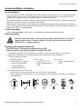
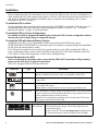
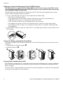
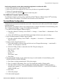
1
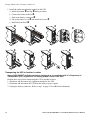
User Manual English APC Smart-UPS 2400/3000 VA 100/110-120 VAC 3U Tower/Rack Mount Uninterruptible Power Supply 990-2233A 02/2005 Introduction/Before Installation Introduction/Before Installation About this Manual The APC Smart-UPS® RT (SURTA2400XLJ/SURTA3000XL/SURTA3000XLTW) is a high-performance Uninterruptible Power Supply (UPS) designed to prevent blackouts, brownouts, sags and surges from reaching your computers, servers, and other sensitive electronic equipment. This manual describes procedures on how to properly unpack and install the UPS, connect the battery and equipment, configure accessories, and start up the system. Illustrations are representative. Your configuration, including components and optional APC equipment, may be different from the models shown in this manual. The user manual is accessible from the supplied CD and the APC Web site, www.apc.com. Contact Information Refer to www.apc.com to contact APC or for additional information about this product. Safety Information Warning Read the Safety Guide before you begin the installation, operate the UPS, or perform equipment maintenance. Failure to comply with safety instructions could result in bodily injury or equipment damage. Unpacking and Equipment Placement The UPS is heavy. Two people are required to lift the UPS. Select a location sturdy enough to handle the weight of the UPS. 1. Unpack the equipment. The packaging is recyclable; save it for reuse or dispose of it properly. 2. Inspect the equipment upon receipt. Notify the carrier and dealer if there is damage. 3. Check the package contents: • • UPS and front bezel UPS literature kit containing: – product documentation – safety information – warranty information 110-120 V models: • PowerChute® CD • Serial communication cable 100 V models: • Serial communication cable 4. Place the UPS where it will be used. – Ensure that air vents on the front and rear of the UPS are not blocked. – Do not operate the UPS where there is excessive dust or the temperature or humidity are outside the specified limits. 40°C 104°F 2.5 cm 95% 0% 2.5 cm Smart-UPS RT 2400/3000 VA Tower/Rack-Mount UPS User Manual 3 Installation Installation Refer to instructions below for information on how to install the UPS in a rack, in a tower configuration, or when installing the UPS with optional battery pack(s). Once the UPS has been placed in the desired tower or rack location, complete the remaining installation steps in sequential order, beginning with “Connect Equipment to the UPS” on page 4. To Install the UPS in a Rack See the installation sheet supplied with the optional rail kit (SURTRK2) to install the UPS in the rack. It is recommended that you remove the battery before attempting to install it in the rack. See “To Install a Replacement Battery” on page 12 for the procedure. To Install the UPS in a Tower Configuration For stability, the UPS is shipped with stabilizing feet. Using the UPS in a tower configuration without the feet may result in bodily injury or equipment damage. To Install the UPS with External Battery Pack(s) In addition to the UPS, if your configuration includes optional Smart-UPS RT battery pack(s) (SURT192XLBP, SURT192XLBPJ), see the battery pack user manual to complete the physical installation for the UPS with external battery pack(s). The UPS must be installed above external battery pack(s) when in a rack. When installing the UPS in a tower configuration, battery pack(s) must be installed to the right of the UPS when facing the front of the UPS. Failure to follow these instructions could result in cabling shortage. Connect Equipment to the UPS Prior to connecting the grounding cable, ensure that the UPS is NOT connected to utility or battery power circuits. See step 1 on page 5 for procedure. The UPS is equipped with the following connectors. Connectors Type Description Serial Com Use only the supplied cable to connect to the serial port. NOTE: A standard serial interface cable is incompatible with the UPS. Normal bypass Manual bypass enables the user to manually put connected equipment into bypass mode. EPO terminal The Emergency Power Off (EPO) terminal allows the user to connect the UPS to the central EPO system. NOTE: Adhere to national and local codes when wiring the EPO switch. TVSS screw The UPS features a Transient Voltage Surge-suppression (TVSS) screw located on the rear panel, for connecting the ground cable on surge suppression devices such as telephone and network line protectors. NOTE: Prior to connecting the grounding cable, disconnect the UPS from the utility power outlet and turn off the UPS. External battery pack connector 4 Optional Smart-UPS RT external battery packs provide extended run-time during power outages. These units support up to ten external battery packs. NOTE: See the APC Web site, www.apc.com for information on the external battery pack, SURT192XLBP, SURT192XLBPJ. Smart-UPS RT 2400/3000 VA Tower/Rack-Mount UPS User Manual Installation Connectors Type Description 120V/3000 VA PDU Receptacles Connect equipment to the Power Distribution Unit (PDU) receptacles on the rear of the UPS. 100V/2400 VA PDU Receptacles Connect equipment to the Power Distribution Unit (PDU) receptacles on the rear of the UPS. 110-120 V 3000 VA PDU Receptacles Connect equipment to the Power Distribution Unit (PDU) receptacles on the rear of the UPS. OUTPUT: 120V 50-60 Hz 20A UNINTERRUPTABLE LR 63938 LIS TE D 42C 2 E95 463 POW ER S UPPLY Model: SURTA3000XL 3000VA / 2100W OUTPUT: 120V 50-60 Hz 15A PER RECEPTACLE GROUP 100V~ 50-60Hz 20A 100V~50-60Hz 24A MAX (NEMA L5-30P) 2400 24A 2.4KVA / 1680W 100V~ 50-60Hz 20A 100V~ 50-60Hz 15A Uninterruptible Power Supply LIS TE D 42C 2 E95 463 輸 :出 110-120V 50-60Hz 20A 輸 :入110-120V~50-60Hz 24A MAX (NEMA L5-30P) LR 63938 LIS TE D 42C 2 E95 463 輸 :出110-120V 50-60 Hz Model: SURTA3000XLTW 3000VA / 2100W 15A PER RECEPTACLE GROUP 1. Connect ground cable of voltage surge-suppression equipment or the optional Smart-UPS RT battery pack to the TVSS screw. 2. Add optional accessories to the Smart-Slot. a. Remove the cover and screws. Discard or save cover. Do not attempt to reinstall it. b. Refer to the accessory manual to install equipment. Smart-UPS RT 2400/3000 VA Tower/Rack-Mount UPS User Manual 5 Installation If Required, Connect the Emergency Power Off (EPO) Feature The EPO interface is a safety extra low voltage (SELV) circuit. Connect it only to other SELV circuits. To avoid damage to the UPS, do not connect the EPO interface to any circuit other than a closure type circuit, properly isolated from the utility. The EPO feature provides immediate de-energizing of the UPS and connected equipment from a remote location, without switching to battery operation. 1. Use one of the following cable types to connect the UPS to the EPO switch. – CL2: Class 2 cable for general use. – CL2P: Plenum cable for use in ducts, plenums, and other spaces used for environmental air. – CL2R: Riser cable for use in a vertical run in a floor-to-floor shaft. – CLEX: Limited use cable for use in dwellings and for use in raceways. – For installation in Canada: Use only CSA certified, type ELC (extra-low voltage control cable). – For installation in other countries: Use standard low-voltage cable in accordance with national and local regulations. 2. Locate the EPO connector on the rear of the UPS. Use a normally-open contact to connect cable to each EPO terminal. Connect the Battery and Install the Front Bezel The battery is shipped in the disconnect position. Do not connect the battery until you are ready to use the equipment. 1. Snap the battery connectors together . 2. Install the front bezel . Connect Power and Start Up the UPS The UPS battery charges when it is connected to utility power and will charge to 85% capacity within three hours. Do not expect full battery run capability from a new battery or after On Battery operation until the battery recharges. To use the UPS as a master ON/OFF switch, ensure all connected equipment is switched on. The equipment will not be powered until the UPS is turned on. 6 Smart-UPS RT 2400/3000 VA Tower/Rack-Mount UPS User Manual Terminal Mode Configuration Avoid using extension cords when connecting equipment to and from the UPS. 1. 2. 3. 4. Ensure that equipment is connected to the UPS. Only use a power cord to plug the UPS into a two-pole three-wire grounded receptable. Turn on all connected equipment. To power up the UPS, press the button on the front panel. For Additional Computer System Security For additional computer system security, install PowerChute® Business Edition Smart-UPS® monitoring software. Refer to the software CD included in the literature kit for instructions. Terminal Mode Configuration Terminal mode can only be used with the serial cable. Connect the serial cable to the UPS before using the terminal program. Shown below is an example of how to use terminal mode to configure the number of external battery packs. See “Configuration Settings” on page 10 for additional information. 1. Exit the PowerChute Business Edition software. a. From the windows PC desktop, select START => Settings => Control Panel => Administrative Tools => Services. b. Select APC PCBE Server and APC PCBE Agent. Right click the mouse and select Stop. 2. Open a terminal program. Example: HyperTerminal a. From the computer desktop, select START => Programs => Accessories => Communication => HyperTerminal. 3. Double-click the HyperTerminal icon. a. Follow the prompts to choose a name and select an icon. Disregard the message, “...must install a modem,” if it is displayed. Click OK. b. Select the COM port that is connected to the UPS. The port settings are: – Bits per second - 2400 – data - bits 8 – parity - none – stop bit - 1 – flow control - none c. Press Enter. 4. Once the terminal window is open, follow these steps to set the number of external battery packs (SURT192XLBP or SURT192XLBPJ): a. Press Enter to initiate terminal mode. Follow the prompts. b. Press 1 to modify UPS settings. Press e (or E) to modify the number of battery packs. c. Enter the number of battery packs, including the internal battery module (Number of packs: 1 = internal battery module, 2 = one SURT192XLBP or SURT192XLBPJ, 3 = two SURT192XLBP or SURT192XLBPJ, etc.) d. Press Enter. e. Follow the prompts. 5. Exit the terminal program. Smart-UPS RT 2400/3000 VA Tower/Rack-Mount UPS User Manual 7 Operation Operation Display Panel Load Percentages Battery Charge Percentages 96% 72% 48% 24% 0% 85% 68% 51% 34% 17% Display Panel Indicators Indicator LED 8 Indicator Title Description On Line The UPS is supplying utility power to the connected equipment. On Battery The UPS is supplying battery power to the connected equipment. Bypass The Bypass LED illuminates indicating that the UPS is in bypass mode. Utility power is sent directly to connected equipment during bypass mode operation. Bypass mode operation is the result of an internal UPS fault, an overload condition, or a user initiated command through an accessory. Battery operation is not available when the UPS is in bypass mode. Fault The UPS detects an internal fault. Overload The connected equipment is drawing more than the UPS power rating allows. Replace Battery/ Battery Disconnected The battery is disconnected or must be replaced. Smart-UPS RT 2400/3000 VA Tower/Rack-Mount UPS User Manual Operation Display Panel Functions Feature Button Feature Title Function Power On Press this button to turn on the UPS. Continue reading for additional capabilities. Power Off Press this button to turn off the UPS output. NOTE: The battery will continue to charge and the fans will continue to run while the UPS is connected to the utility. Cold Start When there is no utility power and the UPS is off, press and hold the button to power up the UPS and connected equipment. NOTE: The UPS will emit two beeps. During the second beep, release the button. Self-Test Automatic: The UPS performs a self-test automatically when tuned on, and every two weeks thereafter (by default). During the self-test, the UPS briefly operates the connected equipment On Battery. Manual: Press and hold the button for a few seconds to initiate the self-test. On Battery Operation The UPS switches to battery operation automatically if the utility power fails. While running On Battery, an alarm beeps four times every 30 seconds. Press the button to silence this alarm. If the utility power does not return, the UPS continues to supply power to the connected equipment until the battery is fully discharged. When 2 minutes of run time remain, the UPS emits a continuous beeping. If PowerChute is not being used, files must be manually saved and the computer must be turned off before the UPS fully discharges the battery. Refer to www.apc.com for information on battery runtimes. The UPS battery runtime differs based on usage and environment. Utility Voltage Measurement Feature Display 100V 118.0 108.7 99.3 90.0 80.6 110/120V 138.2 128.8 119.5 110.1 100.8 Feature Title Diagnostic Utility Voltage Description The UPS has a diagnostic feature that indicates the utility voltage coming into the UPS. The UPS starts a self-test as part of this procedure. The self-test does not affect the voltage display. See “Troubleshooting,” beginning on page 15 for additional information. 1. Press and hold the button to view the utility voltage bar graph indicator. 2. After a few seconds, the five-LED Battery Charge indicator will show the utility input voltage. 3. Refer to the appropriate voltage (100 or 110/120) reading. Values are not listed on the UPS. The actual input voltage is between the displayed value on the list and the next higher value. Smart-UPS RT 2400/3000 VA Tower/Rack-Mount UPS User Manual 9 Configuration Settings Configuration Settings Settings are adjusted through PowerChute software, optional SmartSlot accessory cards, or in terminal mode. Function Factory Default User Selectable Choices Description Automatic Self-Test Every 14 days (336 hours) • Every 7 days (168 hours) • Every 14 days (336 hours) • On start up only • No self-test Set the interval at which the UPS will execute a self-test. UPS ID UPS_IDEN Up to eight characters (alphanumeric) Uniquely identify the UPS, (i.e. server name or location) for network management purposes. Date of Last Battery Replacement Manufacture Date mm/dd/yy Reset this date when you replace the battery module. Minimum Capacity Before Return from Shutdown 0 percent • • • • Alarm Delay Enable Shutdown Delay • 60% • 75% • 90% Specify the percentage to which batteries will be charged following a low battery shutdown before powering connected equipment. • Enable • Mute • Disable Mute ongoing alarms or disable all alarms permanently. 90 seconds • • • • 0s 90 s 180 s 270 s • • • • 360 s 450 s 540 s 630 s Set the interval between the time when the UPS receives a shutdown command and actual shutdown. Low Battery Warning 2 minutes • • • • 2m 5m 8m 11 m • • • • 14 m 17 m 20 m 23 m PowerChute software interface provides automatic, unattended shutdown when approximately two minutes of battery operated run time remains. The low-battery warning beeps are continuous when two minutes of run time remain. Change the low battery warning interval setting to the time that the operating system or system software requires to safely shut down. Synchronized Turn-on Delay 0 seconds • • • • 0s 60 s 120 s 180 s • • • • 240 s 300 s 360 s 420 s Specify the time the UPS will wait after the return of utility power before start up (to avoid branch circuit overload). 10 0% 15% 30% 45% Smart-UPS RT 2400/3000 VA Tower/Rack-Mount UPS User Manual Configuration Settings Factory Default Function User Selectable Choices Description High Bypass Points 100V Models: 110V 120V Models: 133V • • • • • • • • 100V 107V 110V 113V 116V 119V 122V 125V 128V 110-120V • 127V • 130V • 133V • 136V • 139V • 142V • 145V • 148V Maximum voltage that the UPS will pass to connected equipment during internal bypass operation. Low Bypass Points 100V Models: 78V 120V Models: 86V • • • • • • • • 100V 78V 80V 82V 84V 86V 88V 90V 92V 110-120V • 86V • 88V • 90V • 92V • 94V • 96V • 98V • 100V Minimum voltage that the UPS will pass to connected equipment during internal bypass operation. Output Frequency Automatic 50 ± 3 Hz or 60 ± 3 Hz Automatic 50 ± 3 Hz or 50 ± 0.1 Hz 60 ± 3 Hz or 60 ± 0.1 Hz Sets the allowable UPS output frequency. Whenever possible, the output frequency tracks the input frequency. Number of Battery Packs 1 Number of connected battery packs Defines the number of connected battery packs for proper run time prediction. 1 = internal battery module, 2 = one SURT192XLBP or SURT192XLBPJ, 3 = two SURT192XLBP or SURT192XLBPJ, etc. Smart-UPS RT 2400/3000 VA Tower/Rack-Mount UPS User Manual 11 Storage, Maintenance, Transport, and Service Storage, Maintenance, Transport, and Service Storage Store the UPS covered in a cool, dry location with the battery(s) fully charged. At 5° to 113° F (–15° to 45° C), charge the UPS battery every six months. To Install a Replacement Battery This UPS has an easy-to-replace, hot-swappable battery module. Replacement is a safe procedure, isolated from electrical hazards. You may leave the UPS and connected equipment on during the replacement procedure. See your dealer or contact APC at the Web site, www.apc.com for information on replacement battery modules. The battery replacement procedure must include replacing all battery modules in the UPS and connected external battery pack(s). 1. Remove all battery modules in the UPS. a. Remove the front bezel and screws . b. Pull down the battery cover and disconnect the top battery . Once the batteries are disconnected, the connected equipment is not protected from power outages. c. Remove the top battery module . d. Remove the bottom battery module . 2. Recycle old batteries. Be sure to deliver the spent batteries to a recycling facility or ship to APC in the replacement battery packing material. Pb 12 Pb Smart-UPS RT 2400/3000 VA Tower/Rack-Mount UPS User Manual Storage, Maintenance, Transport, and Service Smart-UPS RT 2400/3000 VA Tower/Rack-Mount UPS User Manual 13 Storage, Maintenance, Transport, and Service 1. Install the replacement battery modules in the UPS. a. Install the bottom and top battery modules. b. Connect the battery modules . c. Push in the battery connectors . d. Lift up the battery cover and install the screws . e. Install the front bezel !. ! Transporting the UPS to Another Location Always DISCONNECT the Battery(s) before shipping to be in compliance with U.S. Department of Transportation (DOT) regulations. The battery(s) MUST remain in the UPS. Perform these steps before transporting the UPS to another location. 1. Shut down and disconnect any equipment attached to the UPS. 2. Shut down and disconnect the UPS from the utility or power supply. 3. Unplug the battery connectors. Refer to step 1 on page 12 for additional information. 14 Smart-UPS RT 2400/3000 VA Tower/Rack-Mount UPS User Manual Troubleshooting Service Always DISCONNECT THE BATTERY before shipping the UPS to be in compliance with U.S. Department of Transportation (DOT) regulations. If the UPS requires service do not return it to the dealer. Follow these steps: 1. Review the problems discussed in “Troubleshooting” to eliminate common problems. 2. If the problem persists, contact APC Customer Service through the APC Web site, www.apc.com. – Note the model number of the UPS, the serial number, and the date purchased. If you call APC Customer Service, a technician will ask you to describe the problem and attempt to solve it over the phone. If this is not possible, the technician will issue a Returned Material Authorization Number (RMA#). – If the UPS is under warranty, repairs are free. – Procedures for servicing or returning products may vary internationally. Refer to the APC Web site, www.apc.com for country specific instructions. 3. Disconnect the battery for transport. See “Remove all battery modules in the UPS.” on page 12 for additional information. 4. Pack the UPS and front bezel in its original packaging to avoid damage in transit. If this is not available, refer to www.apc.com for information about obtaining a new set. Never use Styrofoam beads for packaging. Damage sustained in transit is not covered under warranty. 5. Mark the RMA# on the outside of the package. 6. Return the UPS by insured, prepaid carrier to the address given to you by Customer Service. Troubleshooting Use this chart to solve minor UPS installation and operation problems. Refer to www.apc.com with complex UPS problems. Problem and/or Possible Cause Solution UPS will not turn on The battery is not connected properly. button not pushed. Check that the battery connectors are fully engaged. Press the button once to power-up the UPS and connected equipment. The UPS is not connected to utility power supply. Check that the power cable from the UPS to the utility power supply is securely connected. Very low or no utility voltage. Check the utility power supply to the UPS by plugging in a table lamp. If the light is very dim, have the utility voltage checked. UPS will not turn off (Refer to “Display Panel Functions” on page 9.) button not pushed. The UPS is experiencing an internal fault. Press the button once to turn the UPS off. Do not attempt to use the UPS. Unplug the UPS and have it serviced immediately. UPS beeps occasionally Smart-UPS RT 2400/3000 VA Tower/Rack-Mount UPS User Manual 15 Troubleshooting Problem and/or Possible Cause Normal UPS operation when running On Battery. Solution None: The UPS is protecting the connected equipment. Press the button to silence this alarm. UPS is not providing expected backup time The UPS battery is weak due to a recent power outage or battery is near the end of its service life. Charge the battery. Batteries require recharging after extended outages. Batteries can wear faster when put into service often or when operated at elevated temperatures. If the battery is near the end of its service life, consider replacing the battery even if the replace battery LED is not yet illuminated. All LEDs are illuminated and the UPS emits a constant beeping (Refer to “Display Panel Indicators” on page 8.) The UPS is experiencing an internal fault. Do not attempt to use the UPS. Unplug the UPS and have it serviced immediately. Front panel LEDs flash sequentially (Refer to “Display Panel Indicators” on page 8.) The UPS has been shut down remotely through software or an optional accessory card. None: The UPS will restart automatically when utility power returns. All LEDs are off and the UPS is plugged into a wall outlet (Refer to “Display Panel Indicators” on page 8.) The UPS is shut down or the battery is discharged from an extended outage. None: The UPS will restart automatically when utility power is restored and the battery has sufficient or user-specified charge. Bypass and Overload LEDs are illuminated and the UPS emits a sustained alarm tone (Refer to “Display Panel Indicators” on page 8.) The UPS is overloaded. The connected equipment exceeds the specified “maximum load” as defined in Specifications on the APC Web site, www.apc.com. The alarm remains on until the overload is removed. Disconnect nonessential equipment from the UPS to eliminate the overload condition. The UPS continues to supply power in the bypass mode and the circuit breaker does not trip; the UPS will not provide power from batteries in the event of a utility voltage interruption. Bypass LED is illuminated (Refer to “Display Panel Indicators” on page 8.) The bypass has been turned on manually or through an accessory. If bypass is the chosen mode of operation, ignore the illuminated LED. If bypass is not the chosen mode of operation, move the bypass switch on the back of the UPS to the normal position. Fault LED is illuminated (Refer to “Display Panel Indicators” on page 8.) Internal UPS fault. 16 Do not attempt to use the UPS. Turn the UPS off and have it serviced immediately. Smart-UPS RT 2400/3000 VA Tower/Rack-Mount UPS User Manual Troubleshooting Problem and/or Possible Cause Solution Fault and Overload LEDs illuminated and UPS emits a sustained alarm tone (Refer to “Display Panel Indicators” on page 8.) The UPS has ceased sending power to connected equipment. The connected equipment exceeds the specified “maximum load” as defined in Specifications on the APC Web site, www.apc.com. Disconnect nonessential equipment from the UPS to eliminate the overload condition. Press the button, then the button to restore power to connected equipment. The Replace Battery/Battery Disconnected LED is illuminated (Refer to “Display Panel Indicators” on page 8.) Battery is disconnected. flashes and a short beep is emitted every two seconds to indicate the battery is disconnected. Check that the battery connectors are fully engaged. Weak battery. Allow the battery to recharge for 24 hours and perform a self-test. If the problem persists after recharging, replace the battery. Failure of a battery self-test. flashes and a short beep is emitted for one minute. The UPS repeats the alarm every five hours. Allow the battery to recharge for 24 hours. Perform the self-test procedure to confirm the replace battery condition. The alarm stops and the LED clears if the battery passes the self-test. If the battery fails again, it must be replaced. UPS output is maintained during the self-test. There is no utility power There is no utility power and the UPS is off. Use the cold start feature to supply power to the connected equipment from the UPS battery. Press the button for one second and release. The UPS will beep briefly. Press and hold the button again for about three seconds. The unit will emit two beeps. Release the button during the second beep. UPS operates On Battery although line voltage exists Your system is experiencing very high, low, or distorted line voltage. The generator is not correctly sized. Move the UPS to a different outlet on a different circuit: Inadequately sized generators may distort the voltage. Test the input voltage with the utility voltage display. Refer to “Utility Voltage Measurement” on page 9 for additional information. Contact a qualified electrician to correct the building wiring. Diagnostic utility voltage (Refer to “Utility Voltage Measurement” on page 9.) All five LEDs are illuminated. The line voltage is extremely high and should be checked by an electrician. Smart-UPS RT 2400/3000 VA Tower/Rack-Mount UPS User Manual 17 Radio Frequency, Regulatory, Warranty, and Copyright Information Problem and/or Possible Cause There is no LED illumination. Solution The line voltage is extremely low and should be checked by an electrician. On Line LED (Refer to “Display Panel Indicators” on page 8.) There is no LED illumination. The UPS is running On Battery, or it must be turned on. The LED is blinking. The UPS is running an internal self-test. Radio Frequency, Regulatory, Warranty, and Copyright Information Radio Frequency Warning This equipment has been tested and found to comply with the limits for a Class A digital device, pursuant to part 15 of the FCC Rules. These limits are designed to provide reasonable protection against harmful interference when the equipment is operated in a commercial environment. This equipment generates, uses and can radiate radio frequency energy and, if not installed and used in accordance with the instructions, may cause harmful interference. The user is responsible for correcting the interference. Shielded signal cables must be used with this product to ensure compliance with the Class A FCC limits. Regulatory Approvals 120 V models ® LISTED 42C2 E95463 110-120 V models R3A031 100 V models ® LISTED 42C2 E95463 18 Smart-UPS RT 2400/3000 VA Tower/Rack-Mount UPS User Manual Radio Frequency, Regulatory, Warranty, and Copyright Information Limited Warranty American Power Conversion (APC) warrants its products to be free from defects in materials and workmanship for a period of two years from the date of purchase. Its obligation under this warranty is limited to repairing or replacing, at its own sole option, any such defective products. To obtain service under warranty you must obtain a Returned Material Authorization (RMA) number from customer support. Products must be returned with transportation charges prepaid and must be accompanied by a brief description of the problem encountered and proof of date and place of purchase. This warranty does not apply to equipment that has been damaged by accident, negligence, or misapplication or has been altered or modified in any way. This warranty applies only to the original purchaser who must have properly registered the product within 10 days of purchase. EXCEPT AS PROVIDED HEREIN, AMERICAN POWER CONVERSION MAKES NO WARRANTIES, EXPRESSED OR IMPLIED, INCLUDING WARRANTIES OF MERCHANTABILITY AND FITNESS FOR A PARTICULAR PURPOSE. Some states do not permit limitation or exclusion of implied warranties; therefore, the aforesaid limitation(s) or exclusion(s) may not apply to the purchaser. EXCEPT AS PROVIDED ABOVE, IN NO EVENT WILL APC BE LIABLE FOR DIRECT, INDIRECT, SPECIAL, INCIDENTAL, OR CONSEQUENTIAL DAMAGES ARISING OUT OF THE USE OF THIS PRODUCT, EVEN IF ADVISED OF THE POSSIBILITY OF SUCH DAMAGE. Specifically, APC is not liable for any costs, such as lost profits or revenue, loss of equipment, loss of use of equipment, loss of software, loss of data, costs of substitutes, claims by third parties, or otherwise. Copyright Notice Entire contents copyright 2004 by American Power Conversion Corporation. All rights reserved. Reproduction in whole or in part without permission is prohibited. APC, the APC logo, InfraStruXure, PowerChute, Smart-UPS and Symmetra are registered trademarks of American Power Conversion Corporation. All other trademarks are the property of their respective owners. Smart-UPS RT 2400/3000 VA Tower/Rack-Mount UPS User Manual 19