1
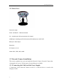
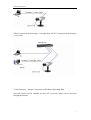
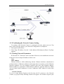
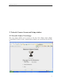
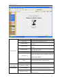
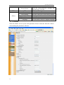
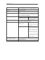
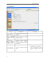
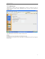
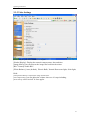
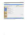
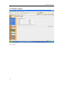
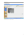
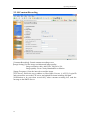
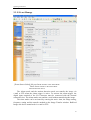
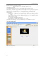
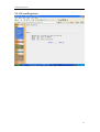
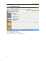
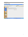
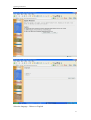
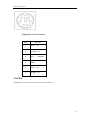
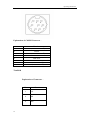
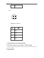
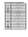
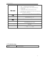
Operating Instructions
Network Camera
Operating Instructions
QSINUFO
`
1
Operating Instructions
Please read this manual before using and save this manual for future
reference.
Introduction
Please check the following items when unpacking.
AC adaptor
— 1 pc.
I/O port link line
— 1 pc.
Category 5 cross cable
— 1 pc.
Setup CD-ROM
— 1 pc.
Operating Instructions
— 1 pc.
Trademarks
¾ Netscape and Netscape Navigator are registered trademarks of Netscape
Communications Corporation in the U.S. and other countries.
¾ Adobe and Acrobat are either registered trademarks or trademarks of Adobe
Systems Incorporated in the United States and/or other countries.
¾ Microsoft, Windows, Windows NT, MS-DOS and ActiveX are either registered
trademarks or trademarks of Microsoft Corporation in the United States and/or
other countries.
¾ Pentium is a registered trademark of Intel Corporation or its subsidiaries in the
United States and other countries.
All other trademarks identified herein are the property of their respective owners.
2
Operating Instructions
Table of Contents
1. Product Introduction ............................................................ 4
1.1 Getting to know the Network Camera.............................................................................4
1.1.1 Main features............................................................................................................4
1.1.2 System Requirements...............................................................................................5
1.2 Camera Feature Locations...............................................................................................5
1.2.1 Front View................................................................................................................5
1.2.2 Rear View.................................................................................................................6
1.3 Network Camera Installation ..........................................................................................6
1.3.1 Connecting the Cable and the Power Supply ...........................................................6
1.3.2 Confirming the Network Camera Setting.................................................................8
1.3.3 Setting Network Parameters.....................................................................................8
Use reset key .....................................................................................................................9
1.3.4 Use ARP command ..................................................................................................9
2. Network Camera Screen and Setup window.................... 11
2.1 Network Camera View Image ....................................................................................... 11
2.2 Viewing the Top View Image screen.............................................................................12
2.3 Setup window—System Configuration.........................................................................13
System Configuration..................................................................................................14
2.3.1 Network..................................................................................................................16
2.3.2 Date/Time...............................................................................................................18
2.3.3 Administrator..........................................................................................................19
2.3.4 General User...........................................................................................................20
2.3.5 Video Settings ........................................................................................................21
2.3.6 Multi-server............................................................................................................22
2.3.7 I/O Ports .................................................................................................................23
2.3.8 Timer Capture.........................................................................................................24
2.3.9 Motion Detect.........................................................................................................25
2.3.10 Constant Recording..............................................................................................26
2.3.11 Event Manage.......................................................................................................27
2.3.12 Event Picture ........................................................................................................28
2.3.13 Event Properties ...................................................................................................29
3
Operating Instructions
2.3.14 PTZ Control Settings............................................................................................30
2.3.15 Other settings .......................................................................................................31
5.
Technical Guides ............................................................. 34
3.1 Maintenance ..................................................................................................................34
3.2 Interfacing to the I/O Connector ...................................................................................34
3.3 I/O .................................................................................................................................34
1. I/O ...............................................................................................................................34
2.COMM .........................................................................................................................35
3.switch ...........................................................................................................................36
6.
Specifications and Troubleshooting............................... 37
6.1
Network Camera reset procedure—default settings................................................37
6.2
Specification............................................................................................................37
6.3
Troubleshooting ......................................................................................................39
4.4 Important Safety Instruction..........................................................................................40
1. Product Introduction
1.1 Getting to know the Network Camera
1.1.1 Main features
¾ Using the Network Camera integrated web server, Motion JPEG, up to 15 frames
per second, can be displayed.
¾ Pan/Tilt operation can move the lens horizontally 120° and downside 45°. This
movable lens allows you to see the situation in the wide room where the object is.
It can adjust the angle easily from the web browser.
¾ Using Multi-Camera screen you can simultaneously view up to four cameras at
various location. Clicking on each Camera Name switches to the Single Camera
screen from the Multi-Camera screen.
¾ The Network Camera allows the 15 users to view the image simultaneously.
¾ Authentication window requires you to enter the administrator/general user ID
and password.
¾ I/O connector consists of the digital input/output terminal. The alarm/timer
trigger can activate the Image Transfer feature which can send the images via
e-mail or FTP (File Transfer Protocol).
4
Operating Instructions
1.1.2 System Requirements
The PC and the network must meet the following technical specifications for the
Network Camera to work properly.
Item
Description
Operating System
Microsoft Windows 98
Microsoft Windows 2000, Microsoft Windows ME
Microsoft Windows NT® 4.0, Microsoft Windows XP
Network Protocol
TCP/IP network protocol installed. (HTTP, FTP, SMTP, TCP,
UDP, IP, ARP, ICMP)
CPU
Pentium® II 300 MHz or greater
Interface
10/100 Mbps Ethernet card and category 5 cables for your
network connection
Web Browser
Internet Explorer 5.0 or later/Netscape Navigator® 4.7
1.2 Camera Feature Locations
1.2.1 Front View
Power Indicator:
During normal operation Power Indicator will be turned on in the default.
Blinking will occur during the following situation.
Audio input port.
5
Operating Instructions
1.2.2 Rear View
From left to right:
RJ45: 100 Base-T:Ethernet Indicator
I/O:Including two I/O inputs and two I/O outputs.
COMM port: including one RS-232 and one RS-485and one LINE OUT。
BNC port: video output.
Reset key
DC IN jack: 12v 1A
Switch: BLC, IRIS, AGC, AWB
1.3 Network Camera Installation
This section explains how you can install the Network Camera. Network Camera has
a integrated web server. Various types of networking are available.
1.3.1 Connecting the Cable and the Power Supply
1.Connection of the Network Camera to the PC or network device is made with
category 5 cable.
6
Operating Instructions
2.Hub Connection needs category 5 straight cable and PC Connection needs category
5 cross cable.
3.LAN (Intranet)、Internet Connection with Ethernet Switching Hub
Network Camera can be installed on the LAN. Network Camera can be accessed
through the Internet.
7
Operating Instructions
1.3.2 Confirming the Network Camera Setting
To confirm if the Network Camera is configured correctly, please access to Top
Page. If the Top Page appears, your Network Configuration is completed.
1. Start up the web browser.
2. Enter "http://IP address : Port No." in the address field and press [Enter]. Top Page
appears.
1.3.3 Setting Network Parameters
IP Network: PC, Network Camera and other IP devices can establish the network.
Each device has an unique IP address of their own..
Note
MAC address
Ethernet defines a 48-bit addressing scheme. Ethernet hardware manufacturers
purchase blocks of Ethernet addresses and assign them in sequence to their Ethernet
interface hardware. No two hardware interfaces have the same Ethernet address.
Ethernet address is sometimes called hardware addresses, physical addresses, Media
Access Control (MAC) addresses, or layer 2 addresses. MAC address is used in this
manual.
ActiveX Controls
If you are using Internet Explorer the first time the PC connects to the Network
Camera, a pop up Security Warning window will appear. The window requests your
8
Operating Instructions
permission to download ActiveX Controls (OCX file) used to display motion video.
Please allow the file to be installed. It is required and will not cause any problems
with other applications on the PC.
Use reset key
IP will be changed to 192.168.1.252. Blinking will occur during the following situation.
Press reset key until the electrical source blinking.
1.3.4 Use ARP command
Attention before assign IP:
Confirm the network camera connected the web correctly, then cut off the power.
Get a single IP address from network manager
MAC address: Each Ball network camera has a single MAC address, MAC address is a
12byte figure, it is singed on the bottom of the Ball camera.(such
as 000ce8xxxxxx )
In the following example, the PC IP address is 192.168.1.6, the IP address of BALL
Network camera is assigned 192.168.1.61, MAC address is 000ce8000001,
Do not use the IP address demonstrated here, please consult with network manager
before you assign the IP address.
The IP address of BALL Network Camera must have the same subnet mask with PC. In
this example, the IP of PC is 192.168.1.6,the IP of network camera is 192.168.1.61,
subnet mask is 255.255.255.0 , if the subnet mask of PC is 255.255.255.128 or more high,
C:\>exit
9
Operating Instructions
C:\>arp -d
C:\>arp -s 192.168.1.61 00-0c-e8-00-00-01
C:\>ping -t 192.168.1.61
Pinging 192.168.1.61 with 32 bytes of data:
Request timed out.
Request timed out.
Request timed out.
Reply from 192.168.1.61: bytes=32 time=5ms TTL=255
Reply from 192.168.1.61: bytes=32 time=4ms TTL=255
Reply from 192.168.1.61: bytes=32 time=4ms TTL=255
Reply from 192.168.1.61: bytes=32 time=4ms TTL=255
Ping statistics for 192.168.1.61:
Packets: Sent = 7, Received = 4, Lost = 3 (42% loss),
Approximate round trip times in milli-seconds:
Minimum = 4ms, Maximum = 5ms, Average =
Control-C
^C
C:\>arp -d
10
2ms
Operating Instructions
2. Network Camera Screen and Setup window
2.1 Network Camera View Image
The view image enables you to access to the Top View Image screen (Single
Camera/Multi-Camera screen). Authentication window can set password for the link
at.
11
Operating Instructions
1.
View Image
Single Camera / Multi-Camera
2.
System Configuration
3. Help
4. Language : English Chinese .
2.2 Viewing the Top View Image screen
The Top View Image screen consists of Single Camera and Multi-Camera screen.
Single Camera screen
Item
12
Description
Operating Instructions
Brightness
Saturation
Volume
Iris
Resolution
Image quality
Brightness control has 17 steps including
Saturation control has 9 steps including
Volume control has 10 steps including
Adjust Iris
Selects 640X 480, 320X240 (default) or 160X120.
Favor clarity/Standard/Favor motion
2.3 Setup window—System Configuration
Setup Page controls all features of the Network Camera. The authentication window
can keep the network security. It enables only administrator to access the Setup Page
by entering ID and Password.
13
Operating Instructions
User: admin
Password: admin
System Configuration
14
Operating Instructions
Network
Date/Time
Administrator
General User
Picture/voice
Basic Setup
Multi-Server
Configures the network setting
Sets the network Date and Time
Sets administrator ID and password for the
security.
Sets General User ID and password for the
security.
Setup image compression ration, voice input
gain and select OCX.
Setup Multi-Server
Setup the alarm occur condition and the
I/O port
output ports status.
Timer
Setup eight timers of alarm timer.
Motion Detect
Constant
Recording
Constant recording
Event Manage
Event Manage
Picture Viewer
Constant recording to Ftp Server.
There are three modes: I/O ports occur,
timer occur and motion detection occur.
Show the event picture, alarm type. alarm id
and alarm time.
15
Operating Instructions
Event Viewer
PTZ
Others
PTZ
Restart
Reset Setting
System information
Update firmware
Language
Show the event properties: message type
and alarm type, ID, time.
PTZ control settings.
Restart the network camera.
Reset the video server form factory default.
Show system information.
Update the system.
You can select Chinese or English. language
2.3.1 Network
Network window can set up the each parameter. Please restart the Network Camera
when making the parameters effective.
16
Operating Instructions
Network Name
Port No.
IP Address and Subnet Mask
DHCP
Default Gateway
DNS
DDNS
4 to 15 English letters,2 to 7 Chinese characters
Set to 80. (Default)
Check Static and set Static IP address and Subnet
Mask.
Please check DHCP when the ISP uses the DHCP
server function that assigns an IP address to the
Network Camera automatically.
IP Gateway
Enter it in gateway IP..
PPPOE Gateway
Enter it in PPPOE user
name and password.
You must enter the proper address when use the Host
name of the e-mail or FTP function.
Network
Camera log in management server
of network camera to brows
Manage Server
after input user name and
password.
DDNS
input domain name to
directly remote brows
after input user name
and password and free
domain name .
Max. Bandwidth Usage
It can restrict the transmit bandwidth. Select from 0.1
to Unlimited Mbit/s.
MAC
17
Operating Instructions
2.3.2 Date/Time
Item
Instructions
1.Date and Time
Display current Camera date
and time.
2.Set
Network
Camera Date and
Time
Network Camera can adjust
the internal clock.
(1)Synchronize
Current
With
Computer Time
Make the Network Camera the
internal
clock
together
current the calculator clock is
synchronous
Limitation
•
(2) Set Manually
18
Set time to adjust the internal
clock.
•
The date is from 1970 to 2039 ,
according to yyyy- mm- dd.
Time is format that 24 hours
system, according to hh: mm:
ss.
Operating Instructions
2.3.3 Administrator
Administrator window allows the administrator to limit or exclude the access to
selected Network Camera feature. Individual levels of access can be defined for
multiple users.
The administrator can select one of three security levels:
[None]
[Administrator only]: Setup Page for Administrator only
[Administrator and General User]: Setup Page for Administrator and Viewer Page for
General User
19
Operating Instructions
2.3.4 General User
General User window allows the administrator to create the General User ID and password for the
security level defined as General User.
User Name List: User Name List displays the registered user name.[Delete] and [Modify]
deletes/modifies the General User in the list.
New User: Enter the General User Name, password to confirm.
20
Operating Instructions
2.3.5 Video Settings
[Video Adjust ]: Permit General User adjust.
[Header Display]: Display the network camera name, date and time.
[Image Mirror]:you can browse the image like look into the mirror.
[BLC Control]:enable BLC.
[White Balance]: Auto (default)、Electric Bulb、Natural fluorescent light、Solar light、
Hold.
[Compression Ratio]: Compress the image and the ratio.
[Voice Input Gain]: you can adjust the volume. there are 10 steps including.
[OCX select]: select ActiveX or Java applet.
21
Operating Instructions
2.3.6 Multi-server
Multi-Camera window enables the setting of Multi-Camera screen. 2nd to 4th
cameras are named on this Multi-Camera window.
22
Operating Instructions
2.3.7 I/O Ports
Setup alarm occur condition: when the electricity falling.
when the electricity rising.
output ports status :high impedance and low impedance.
output port status keep live times.
23
Operating Instructions
2.3.8 Timer Capture
The timer mode can be activated by entering the
every week.
24
active time. You can set eight timers of
Operating Instructions
2.3.9 Motion Detect
Setup the alarm scope of motion detection.
25
Operating Instructions
2.3.10 Constant Recording
[Constant Recording]: Permit constant recording or not.
[Image Setting]: Set the image resolution and image quality.
Image resolution: 640 x 480/320 x 240/160 x 120
Image quality: Favor Clarity/Standard/Favor Motion
[Image Frequency]: Sets the interval to send the image.
[FTP Server]: Enters the server address or Host Name, Port no. (1–65535), Login ID
and password to access the FTP server and upload file name including full path.
[Notification to be sent when record fail]: when constant recording fail, send the
message to the SMTP Server.
26
Operating Instructions
2.3.11 Event Manage
[Event Source Select]:I/O port Occur Transfer in the Alarm Mode
Timer Occur Transfer in the Timer Mode
Motion Detection Occur
The Alarm mode and the motion detection mode can transfer the image via
e-mail or FTP when the alarm trigger is active. To activate the alarm trigger, the
digital input terminal of the I/O Connector must be connected with the external
sensors/devices. The Alarm mode can send the e-mail without transferring the image.
The timer mode can be activated by entering the active time, the image setting,
frequency setting and the transfer method on the Image Transfer window. Buffered
Image can also be transferred via e-mail or FTP.
27
Operating Instructions
[Image Setting]: Set the image resolution
Image resolution: 640 x 480/320 x 240/160 x 120
[Image Buffer Setting]:
[Over Buffer Setting]:over write the buffer or not when the buffer is full.
[FTP Server]: Enters the server address or Host Name, Port no. (1–65535), Login ID
and password to access the FTP server and upload file name including full path.
[SMTP Server]:
SMTP Server IP address or host name: Sets the SMTP server address or Host
Name.
From (Reply): Enter the e-mail address of [Reply-to]. [To] can be the same
address as From (Reply).
To : Enter the e-mail address of receiver.
Subject & Text : Sets the subject and text of the e-mail.
[Network Camera Manager Server]:set the manager server IP address or name .
2.3.12 Event Picture
Show the event picture.
28
Operating Instructions
2.3.13 Event Properties
Show the event properties. Message type ,alarm type , alarm id and alarm time.
29
Operating Instructions
2.3.14 PTZ Control Settings
[PTZ Control]: Permit General User control or not.
[COM Settings]: Sets baud rate.
[PTZ Control Identity]: Sets PTZ ID.
[Select PTZ Control Driver]: Select PTZ protocols.
30
Operating Instructions
2.3.15 Other settings
Restart the network camera.
31
Operating Instructions
Reset the video server form factory default. The IP will be changed to 192.168.1.252.
Show the system information: firmware version and software version..
32
Operating Instructions
Select the language : Chinese or English.
33
Operating Instructions
5. Technical Guides
3.1 Maintenance
To keep the Network Camera in the good condition, maintenance plays an
important part. Please keep maintenance when using the Network Camera.
Network Camera
• Network Camera is intended for indoor use only. Prolonged exposure to direct
sunlight or halogen light may damage the CMOS sensor.
The Fixed Focused lens
• Do not touch the movable lens part around the Fixed Focus Lens even in the power
off state. If you touch the movable lens part in the front of the Network Camera, it
may damage the Network Camera.
• Do not touch the Fixed Focus Lens. It may leave a fingerprint and can cause the
image to be out of focus. This can also take away the protective coating on the Fixed
Focus Lens.
• Clean the lens with a Lens Cleaning paper.
3.2 Interfacing to the I/O Connector
The Alarm mode in the Image Transfer feature requires the external sensors/devices to
be connected to the digital input terminal of the I/O Connector. The sensor is customer
provided and can be a door sensor or infrared ray intruder sensor. In most applications
a simple contact closure is all that is required.
3.3 I/O
1. I/O
I/O ports have two I/O inputs and two I/O outputs
34
Operating Instructions
Explanation of I/O Connector:
Pin
Function
1
I/O-IN
2
I/O-OUT
3
+12V
4
DGND
5
I/O-IN
6
I/O-OUT
(1)
(1)
(<100mA)
(2)
(2)
2.COMM
COMM ports have one RS-232 , RS-485 and one LINE OUT。
35
Operating Instructions
Explanation of COMM Connector::
Function
PIN
232/(RXD UFO-II-H Å)
DGND
1
2
4
232/(TXD UFO-II-H Æ)
DGND
5
LINE OUT
6
AGND
7
485/(B UFO-II-H Å)
8
485/(A UFO-II-H Æ)
3
3.switch
Explanation of Connector::
Pin
36
Function
1
BLC
2
IRIS
3
AGC
Operating Instructions
4
AWB
4. LENS
2
1
4
3
Explanation of Connector::
No.
名称
1
DAMP-
2
DAMP+
3
DRIVE+
4
DRIVE-
6. Specifications and Troubleshooting
6.1 Network Camera reset procedure—default settings
If the user forgets the settings or passwords, the Network Camera can be easily reset
to the default settings.
6.2 Specification
37
Operating Instructions
Item
Network Protocols
TCP/IP, HTTP, FTP, SMTP, DDNS, DNS,DHCP, PPPOE
Network Connection
MODEM、ISDN、XDSL、LAN
CPU
32 bits,RISC CPU
FLASH
4MB
RAM
32M
Operation system
Embedded real time operation system
Image Compression
JPEG, MOTION-JPEG
System Requirements
Microsoft IE, Netscape
Performance
25(SIF),15(VGA)
Resolution
640×480,320×240,160×120
Alarm image buffer
80frames
Event trigger & Action
I/O ports
38
UFO-Ⅱ-L network camera
I/O Trigger,timer Trigger,motion detection
2 I/O in & 2 I/O
out
indoor/outdoor
indoor
Audio(optional)
G.711,G.726,G.723.1,G.729
Sensor
1/3,SHARP, CCD
plane definition
480 line
LUX
1.0 Lux(F1.2)
Operating Instructions
•
•
•
•
•
Video control
•
•
AWB: White Balance (ATW/Push/Indoor/Outdoor)
AGC:
Automatic Gain Control (On/Off)
Manual Electronic Shutter (1/50 or 1/60 when AES off)
Auto DC IRIS
Auto Electronic Shutter (AES on/off, BLC on/off)
Day/Night feature (Color/B.W. auto switch in low illumination)
BLC: Back light compensation
Direct Drive Lens; Build-in VR for DC level adjustment
LENS
Auto DC Iris F1.2~64 Lens
Serial port
One RS-232 Serial port
P/T/Z
One RS-485 Serial port for PTZ camera control
Size
110X102X54mm(expect bracket)
Power supply
12DC/4W
Operating Temperature
(-20℃)——(+50℃)
6.3 Troubleshooting
Problem
Cause and Remedy
39
Operating Instructions
When the Top Page does
• Enter the correct IP address set up to the Network
not appear.
Camera.
• IP address of the PC and the Network Camera must be in
the same class of the private IP address on the LAN.
• Confirm if the Ethernet, the hub and the LAN card
indicators are on. If any indicator is off, check the network
connections.
• The network congestion prevents the Top Page from
appearing quickly. Please wait for a while.
• The proxy server may prevent you from connecting
directly to the Network Camera, please set up not to use
the proxy server.
When forgetting the 1. Reset the Network Camera by pressing the CLEAR
password to access the
SETTING button.
Setup Page.
2. Reconfigure the Network Camera.
4.4 Important Safety Instruction
When using this unit, basic safety precautions should always be followed to reduce the risk of fire,
electric shock, or personal injury.
a) Read and understand all instructions.
b) Unplug this unit from AC outlets before cleaning. Do not use liquid or aerosol cleaners.
Use a damp cloth for cleaning.
c) Do not use this unit near water, for example, near a bathtub, washbowl, kitchen sink, or
the like.
d) Place this unit securely. Serious damage and/or injury may result if the unit falls.
e) Use proper power source. If you are not sure of the type of power supplied to your home,
consult your dealer or local power company.
f) Do not place objects on the power cord. Install the unit where no one can step or trip on
the cord.
g) To reduce the risk of electric shock, do not disassemble this product, but take it to a
qualified serviceman when some service or repair work is required. Opening or removing
covers may expose you to dangerous voltage or other risks. Incorrect reassembly can
cause electric shock when the appliance is subsequently used.
h) Unplug this unit from the wall outlet and refer servicing to an authorized serviette when
the following conditions occur:
1) When the power supply cord or plug is damaged or frayed.
2) If liquid has been spilled into the unit.
40
Operating Instructions
3) If the unit has been exposed to rain or water.
4) If the unit does not work normally by following the operating
instructions.
5) If the unit has been dropped or physically damaged.
6) If the unit exhibits a distinct change in performance.
WARNING
TO PREVENT RISK OF FIRE OR ELECTRIC SHOCK, DO NOT EXPOSE THIS
PRODUCT TO RAIN OR MOISTURE.
41