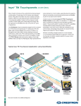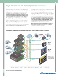
1
Digi 001
Quick Start Guide
Version 5.0.1 for Macintosh and Windows 98
Digidesign Inc.
3401-A Hillview Avenue
Palo Alto, CA 94304 USA
tel: 650·842·7900
fax: 650·842·7999
Technical Support (USA)
650·842·6699
650·856·4275
Product Information (USA)
650·842·6602
800·333·2137
Fax on Demand (USA)
1-888-USE-DIGI (873-3444)
World Wide Web
www.digidesign.com
Digidesign FTP Site
ftp.digidesign.com
Copyright
This User’s Guide is copyrighted ©2000 by Digidesign, a
division of Avid Technology, Inc. (hereafter “Digidesign”), with
all rights reserved. Under copyright laws, this manual may not
be duplicated in whole or in part without the written consent of
Digidesign.
DIGIDESIGN, AVID and PRO TOOLS are trademarks or
registered trademarks of Digidesign and/or Avid Technology,
Inc. All other trademarks are the property of their respective
owners.
All features and specifications subject to change without
notice.
PN 932708007-00 REV A 05/00
Any modifications to the unit, unless expressly approved by
Digidesign, could void the user's authority to operate the
equipment.
DECLARATION OF CONFORMITY
We Digidesign,
3401-A Hillview Avenue
Palo Alto, California 94304-1348, USA
650-842-7900
declare under our sole responsibility that the product
Canadian Compliance Statement:
This Class B digital apparatus complies with Canadian ICES003
Cet appareil numérique de la classe B est conforme à la norme
NMB-003 du Canada
Digi 001
complies with Part 15 of FCC Rules.
Australian Compliance
Operation is subject to the following two conditions: (1) this
device may not cause harmful interference, and (2) this device
must accept any interference received, including interference
that may cause undesired operation.
NOTE: This equipment has been tested and found to comply
with the limits for a Class B digital device, pursuant to Part 15
of the FCC Rules. These limits are designed to provide
reasonable protection against harmful interference in a
residential installation. This equipment generates, uses, and
can radiate radio frequency energy and, if not installed and
used in accordance with the instructions, may cause harmful
interference to radio communications. However, there is no
guarantee that interference will not occur in a particular
installation. If this equipment does cause harmful interference
to radio or television reception, which can be determined by
turning the equipment off and on, the user is encouraged to try
and correct the interference by one or more of the following
measures:
• Reorient or locate the receiving antenna.
• Increase the separation between the equipment and
receiver.
• Connect the equipment into an outlet on a circuit different
from that to which the receiver is connected.
• Consult the dealer or an experienced radio/TV technician
for help.
European Compliance
contents
Chapter 1. Digi 001 Introduction . . . . . . . . . . . . . . . . . . . . . . . . . . . . . . . . . . . . . . . . . . . . . . 1
About Digi 001 . . . . . . . . . . . . . . . . . . . . . . . . . . . . . . . . . . . . . . . . . . . . . . . . . . . . . . . . . . 1
System Requirements . . . . . . . . . . . . . . . . . . . . . . . . . . . . . . . . . . . . . . . . . . . . . . . . . . . . . 2
Digidesign Registration . . . . . . . . . . . . . . . . . . . . . . . . . . . . . . . . . . . . . . . . . . . . . . . . . . . . 3
About the Guides . . . . . . . . . . . . . . . . . . . . . . . . . . . . . . . . . . . . . . . . . . . . . . . . . . . . . . . . . 3
Chapter 2. Macintosh Configuration . . . . . . . . . . . . . . . . . . . . . . . . . . . . . . . . . . . . . . . . . . . 5
Installing the Digi 001 Hardware . . . . . . . . . . . . . . . . . . . . . . . . . . . . . . . . . . . . . . . . . . . . . . 5
Installing the Pro Tools LE Software . . . . . . . . . . . . . . . . . . . . . . . . . . . . . . . . . . . . . . . . . . . . 7
Installing and Configuring OMS . . . . . . . . . . . . . . . . . . . . . . . . . . . . . . . . . . . . . . . . . . . . . . . 9
Hard Drive Requirements . . . . . . . . . . . . . . . . . . . . . . . . . . . . . . . . . . . . . . . . . . . . . . . . . . 12
Launching Pro Tools LE the First Time . . . . . . . . . . . . . . . . . . . . . . . . . . . . . . . . . . . . . . . . . 13
Chapter 3. Windows 98 Configuration . . . . . . . . . . . . . . . . . . . . . . . . . . . . . . . . . . . . . . . . 15
BIOS and System Modifications . . . . . . . . . . . . . . . . . . . . . . . . . . . . . . . . . . . . . . . . . . . . . . 15
Installing the Digi 001 Hardware . . . . . . . . . . . . . . . . . . . . . . . . . . . . . . . . . . . . . . . . . . . . . 16
Installing the Windows 98 Wave Drivers . . . . . . . . . . . . . . . . . . . . . . . . . . . . . . . . . . . . . . . 19
Installing the Pro Tools LE Software . . . . . . . . . . . . . . . . . . . . . . . . . . . . . . . . . . . . . . . . . . . 20
Hard Drive Requirements . . . . . . . . . . . . . . . . . . . . . . . . . . . . . . . . . . . . . . . . . . . . . . . . . . 22
Launching Pro Tools LE the First Time . . . . . . . . . . . . . . . . . . . . . . . . . . . . . . . . . . . . . . . . . 24
Contents iii
Chapter 4. Connecting Your Studio . . . . . . . . . . . . . . . . . . . . . . . . . . . . . . . . . . . . . . . . . . 25
Digi 001 I/O Box Inputs and Outputs . . . . . . . . . . . . . . . . . . . . . . . . . . . . . . . . . . . . . . . . . 25
Output Modes . . . . . . . . . . . . . . . . . . . . . . . . . . . . . . . . . . . . . . . . . . . . . . . . . . . . . . . . . 29
Making Signal Connections to Digi 001 . . . . . . . . . . . . . . . . . . . . . . . . . . . . . . . . . . . . . . . 30
Connecting Audio Sources to Digi 001 . . . . . . . . . . . . . . . . . . . . . . . . . . . . . . . . . . . . . . . . 32
Studio Setup Diagrams . . . . . . . . . . . . . . . . . . . . . . . . . . . . . . . . . . . . . . . . . . . . . . . . . . . 37
Connecting an ADAT to Digi 001 . . . . . . . . . . . . . . . . . . . . . . . . . . . . . . . . . . . . . . . . . . . . 39
Using Monitor Mode . . . . . . . . . . . . . . . . . . . . . . . . . . . . . . . . . . . . . . . . . . . . . . . . . . . . . 40
MIDI Connections . . . . . . . . . . . . . . . . . . . . . . . . . . . . . . . . . . . . . . . . . . . . . . . . . . . . . . . 41
Using External Effects Devices . . . . . . . . . . . . . . . . . . . . . . . . . . . . . . . . . . . . . . . . . . . . . . 41
Chapter 5. Working with the Demo Session . . . . . . . . . . . . . . . . . . . . . . . . . . . . . . . . . . . 43
Playing the Demo Session . . . . . . . . . . . . . . . . . . . . . . . . . . . . . . . . . . . . . . . . . . . . . . . . . 43
Mixing the Demo Session Tutorial . . . . . . . . . . . . . . . . . . . . . . . . . . . . . . . . . . . . . . . . . . . 48
Plug-Ins . . . . . . . . . . . . . . . . . . . . . . . . . . . . . . . . . . . . . . . . . . . . . . . . . . . . . . . . . . . . . . 54
Cool Mix Tricks: The Big Mute . . . . . . . . . . . . . . . . . . . . . . . . . . . . . . . . . . . . . . . . . . . . . . 57
MIDI . . . . . . . . . . . . . . . . . . . . . . . . . . . . . . . . . . . . . . . . . . . . . . . . . . . . . . . . . . . . . . . . 60
Chapter 6. Recording . . . . . . . . . . . . . . . . . . . . . . . . . . . . . . . . . . . . . . . . . . . . . . . . . . . . . . . 63
Routing Audio to a Track . . . . . . . . . . . . . . . . . . . . . . . . . . . . . . . . . . . . . . . . . . . . . . . . . . 63
Setting Digi 001 Input Levels. . . . . . . . . . . . . . . . . . . . . . . . . . . . . . . . . . . . . . . . . . . . . . . 64
Recording an Audio Track . . . . . . . . . . . . . . . . . . . . . . . . . . . . . . . . . . . . . . . . . . . . . . . . . 67
Recording MIDI . . . . . . . . . . . . . . . . . . . . . . . . . . . . . . . . . . . . . . . . . . . . . . . . . . . . . . . . 71
Recording with a Footswitch . . . . . . . . . . . . . . . . . . . . . . . . . . . . . . . . . . . . . . . . . . . . . . . 72
Recording with an ADAT . . . . . . . . . . . . . . . . . . . . . . . . . . . . . . . . . . . . . . . . . . . . . . . . . . 73
Index . . . . . . . . . . . . . . . . . . . . . . . . . . . . . . . . . . . . . . . . . . . . . . . . . . . . . . . . . . . . . . . . . . . . . 75
iv Digi 001 Quick Start Guide
chapter 1
Digi 001 Introduction
About Digi 001
Thank you for purchasing Digi 001, a cross-platform solution for music, sound design, and
multimedia production. The Digi 001 package includes the following:
• Installer CD-ROM containing Pro Tools LE recording software, RTAS (Real-Time Audio
Suite) Plug-Ins, and online PDF guides
• Digi 001 Quick Start Guide, documents installation, configuration, and basic tutorials for
Digi 001
• Digi 001 PCI card, connects to I/O Box and provides 8 channels of Optical I/O
• Digi 001 I/O Box with connections for analog audio, S/PDIF, and MIDI
• Rack ears, lets you install the I/O Box in a standard 19" rack
• I/O box connector cable, connects the Digi 001 PCI card to the I/O Box
• Optical cable, connects the Digi 001 to an ADAT or S/PDIF audio device
• Digidesign Registration card
Pro Tools LE Capabilities
The Pro Tools LE software provides the following capabilities:
• Record and play up to 24 audio tracks of digital audio (depending on the capabilities of
your computer)
• Record and play up to 128 MIDI tracks
• Use non-linear, random-access editing and mix automation
• Process audio with up to 5 RTAS Plug-Ins per track, limited only by the capabilities of
your computer
• Use up to 5 inserts and 5 sends per track
• Route up to 16 busses
• Work with16-bit or 24-bit sessions
Chapter 1: Digi 001 Introduction 1
▲ Pro Tools LE uses your computer’s CPU to mix and process audio tracks (host
processing). Computers with faster clock speeds yield higher track counts and
more plug-in processing.
Digi 001 Capabilities
The Digi 001 provides the following inputs and outputs:
• 8 analog audio inputs, 2 with mic preamps
• Switchable 48V phantom power on mic preamps
• 8 analog outputs and stereo monitor output
• Stereo headphone output
• Optical input for 8 channels of ADAT input or 2 channels of S/PDIF input
• Optical output for 8 channels of ADAT output or 2 channels of S/PDIF output
• 2 RCA channels of S/PDIF digital I/O
• MIDI in and out, providing up to 16 channels of MIDI I/O
In addition, the Digi 001 includes a footswitch jack for punching in and out while
recording.
System Requirements
Digi 001 can be used on a Power Macintosh or Intel computer.
To use Pro Tools LE on a Macintosh, you need:
•
•
•
•
•
•
A Digidesign-qualified Power Macintosh (G3/G4 recommended)
Mac OS 8.6 or 9.0
At least 128 MB RAM (192 MB recommended)
CD-ROM drive for software install
QuickTime 4.0 or higher (included with Pro Tools LE)
OMS 2.3.8 or higher (included with Pro Tools LE)
To use Pro Tools LE on Windows 98, you need:
•
•
•
•
A Digidesign-qualified Intel computer (PIII recommended)
Windows 98, Second Edition
At least 128 MB RAM (192 MB recommended)
CD-ROM drive for software install
2 Digi 001 Quick Start Guide
Compatibility Information
Digidesign can only assure compatibility and provide support for devices it has tested and
approved. For a list of Digidesign-qualified computers, SCSI accelerator cards, hard drives,
diskette drives, and serial port adapters, refer to the latest compatibility information on the
Digidesign Web site (www.digidesign.com):
Digidesign Registration
Make sure to complete and return the registration card included with Digi 001. Registered
users are entitled to one year of free technical support, and will receive periodic software
updates and upgrade notices.
About the Guides
This Quick Start Guide will get you started using Digi 001 to record, edit, and mix multiple
audio and MIDI tracks. For additional information, see the following online guides:
• Pro Tools Reference Guide, documents in detail Pro Tools LE software
• DigiRack Plug-Ins Guide, documents how to use the RTAS and AudioSuite Plug-Ins
included with Pro Tools LE
• MIDI Controllers Guide, documents how to use MIDI control surfaces like the Mackie HUI
with Pro Tools LE
• Keyboard Shortcuts (Macintosh and Windows), lists keyboard shortcuts for Pro Tools LE
PDF versions of these guides are installed automatically with Pro Tools LE, and can be
easily accessed from the Help menu in Pro Tools LE. To read the guides online, or print
them, you must install Acrobat Reader (included on the Pro Tools LE Installer CD).
Chapter 1: Digi 001 Introduction 3
Conventions Used in This Guide
Digidesign guides use the following conventions to indicate menu choices and key
commands:
Convention
Action
File > Save Session
Choose Save Session from the File menu
Control+N
While pressing the Control key, press the N key
Option-click
While pressing the Option key, click the mouse button
Right-click (Windows)
Click with the right mouse button
The following symbols are used to highlight important information:
✽ User Tips are helpful hints for getting the most from your system.
▲ Important Notices include information that could affect your data or the perfor-
mance of your system.
☞ Cross References point to related sections in other Digidesign guides.
Choose and Select
The words “choose” and “select” are often interchangeable in conversational english. In
this guide, however, there is a distinction between the two terms.
Select When the guide instructs you to select something, it stays selected. This is the case
with dialog box options and menu items that enable or disable an option.
Choose When the guide instructs you to choose something, a one-time action is performed.
This is the case with most menu commands; they perform their chosen action only once.
4 Digi 001 Quick Start Guide
chapter 2
Macintosh Configuration
Installing the Digi 001 Hardware
Before installing the Pro Tools LE software, first install the Digi 001 card.
To install the Digi 001 card in your Macintosh:
1 Turn off your computer. Leave it plugged in so that it is grounded.
2 Open the computer case. If necessary, refer to the manufacturer’s instructions for details.
3 Remove the rear slot cover and screw of any available PCI expansion slot.
PCI card installation for Macintosh Blue & White G3
4 Before handling the Digi 001 card, discharge any static electricity by touching the outer
casing of the power supply.
5 Remove the Digi 001 card from its anti-static bag.
6 Hold the card gently by the top edges, and line up its PCI connector with the PCI slot
inside the computer.
Chapter 2: Macintosh Configuration 5
7 When the connector and slot are aligned, press the card into the slot using firm, even
pressure. The card should “pop” into place. Secure the card with the previously removed
screw. Make sure the card’s audio connectors are accessible through the rear slot of the
computer.
Digi 00I card
Available PCI slot
in your computer
PCI card installation
8 Close the computer case.
Connecting the Digi 001 I/O Box
▲ Your computer must be off when you connect or disconnect the I/O Box.
To connect the Digi 001 I/O box:
1 Locate the connector cable with the wide ends that came with your Digi 001.
2 Align a cable end with the connector on the Digi 001 PCI Card, and insert the cable into
the connector until it clicks into place.
Connect cable here
Digi 001 PCI Card (outside computer view) showing cable connector
3 Align the other cable end with the Computer connector on the Digi 001 I/O Box, and
insert the cable into the connector until it clicks into place.
Connect cable here
4 Turn on your computer.
6 Digi 001 Quick Start Guide
Installing the Pro Tools LE Software
Apple System Software Settings
To ensure optimum performance with the Pro Tools LE software, configure the Apple
System software with the following settings.
To configure the Apple System software:
1 In the Memory Control Panel do the following:
• Set Virtual Memory to Off.
• Set the Ram Disk to Off.
• Set the Disk Cache to a Custom Setting of 512K.
2 In the Energy Saver Control Panel, set the “inactive” time to Never.
3 In the Appearance Control Panel do the following:
• Click the Fonts tab and set the Large System Font to Chicago. In addition, deselect
“Smooth all fonts on screen.”
• Click the Sound tab and select None from the Sound Track pop-up menu.
4 If using a Power Macintosh 9600, set the number of colors to 256 in the
Monitors & Sound Control Panel.
5 In the Extensions Manager Control Panel do the following:
Extensions Manager Control Panel
• Choose Mac OS 8.6 Base (or Mac OS 9.0 Base) from the Selected Set pop-up menu.
• Click Restart to restart your computer.
Chapter 2: Macintosh Configuration 7
Pro Tools LE Installation
After the Apple System software settings are configured, install Pro Tools LE.
To install Pro Tools LE on your Macintosh:
1 Insert the Pro Tools LE Installer CD in your CD-ROM drive. Locate and double-click
“Install Pro Tools LE.”
2 At the Install Screen, select the install option for Pro Tools LE, and set the Install Location
to your Startup hard drive. Click Install.
3 Follow the on-screen installation instructions.
4 When installation is complete, click Quit (not Restart) and install the demo sessions (see
“Installing the Demo Session” on page 8) and OMS (see “Installing and Configuring
OMS” on page 9).
Installing the Demo Session
The Digi 001 system includes two demo sessions, SoundCheck Digi001, which you can use
to verify that your system is working, and Be There LE Digi001, a more full-featured demo
that you can use to test system playback, and to learn some features of Pro Tools LE using
the tutorial information in Chapter 5: Working with the Demo Session.
▲ Before installing the demo sessions to your audio drive, make sure the drive is
configured as described in “Hard Drive Requirements” on page 12.
To install the demo sessions:
1 Insert the Pro Tools LE Installer CD in your CD-ROM drive. Locate and double-click
“Install PT LE Demo Session.”
2 At the Install Screen, make sure the install options for “Be There Session” and
“SoundCheck Session” are selected.
3 Set the Install Location to your audio drive and click Install.
4 When installation is complete, click Quit.
8 Digi 001 Quick Start Guide
Installing and Configuring OMS
(Macintosh Only)
To use Pro Tools on the Macintosh you must first install and configure the Open Music
System (OMS). OMS, which is included on the Pro Tools Installer CD, has the following
capabilities:
• Keeps track of which MIDI devices you are using, how they are connected, and which
patches they are using
• Enables MIDI hardware to communicate with your music applications
• Provides timing services and inter-application communication
OMS stores a description of your MIDI studio in Studio Setup documents, which are edited
in the OMS Setup application. Once OMS is configured, your music applications know
which MIDI devices you are using by referencing the current Studio Setup document.
The following sections provide basic instructions for installing and configuring OMS. For
more detailed information, refer to the online OMS Guide installed with Pro Tools.
Installing OMS
The OMS Installer is located on your Pro Tools Installer CD-ROM.
To install OMS:
1 Insert the Pro Tools Installer CD in your CD-ROM drive.
2 Open the “OMS Installer” folder and double-click the OMS installer.
3 At the Install Screen, select the Easy Install option, and set the Install Location to your
Startup hard drive. Click Install.
4 Follow the on-screen installation instructions.
5 When the installation is complete, restart your Macintosh.
Configuring a New Studio Setup
(First-Time OMS Users Only)
Before configuring OMS, make sure the Digi 001 and I/O Box have been installed, and that
any other MIDI interfaces are connected according to the manufacture’s instructions and
turned on.
To configure a New Studio Setup in OMS:
1 Launch the OMS Setup application. If OMS has not yet been configured, you’ll be
prompted to configure a New Studio Setup. Click OK.
Chapter 2: Macintosh Configuration 9
2 Select whether your MIDI interface is connected to the Modem or Printer port. If using
a USB or PCI-based MIDI interface, leave both ports unchecked. Click Search.
Ports for OMS Driver Search
OMS searches for and displays any detected MIDI interfaces, MIDI cards, and OMS drivers.
If your interface is not detected, click Troubleshoot. Once your interface is detected, you
are prompted to search for MIDI instruments connected to your interface.
3 Click OK to search for MIDI devices connected to your MIDI interface. To be detected, the
device must be turned on with both of its MIDI ports connected to your MIDI interface.
OMS Driver Setup
OMS searches for and displays any detected MIDI devices. Some older instruments, as well
as some newer ones, may not be recognized by the OMS auto-detection routines.
Undefined OMS device
Devices not recognized by OMS appear with a red question mark and are named based on
the interface or port to which they are connected. These devices can be defined as
necessary within the OMS Setup application (see “Defining MIDI Devices in OMS” on
page 11).
4 Click OK to save your Studio Setup document.
10 Digi 001 Quick Start Guide
Defining MIDI Devices in OMS
To define a MIDI device in OMS Setup:
1 Double-click the device’s icon in the Studio Setup window.
2 In the MIDI Device Info dialog, select the Manufacturer and Model for the device from
the pop-up menus. If the device is not listed, leave the Model set to “other” and enter a
name for the device.
MIDI Device Info
3 Select the Receiving Channel for the device. If receiving multiple channels, select the
option for “Is Multitimbral.”
4 If you will record from the device in Pro Tools, select the option for “Is Controller.” If the
device will be a source or destination for MIDI Time Code, Beat Clock, or MMC, select
the appropriate option.
5 Click Ok.
Disabling Serial DMA in OMS
Pro Tools requires that you deselect the “Use Apple Serial DMA Driver When Available”
option in OMS Setup. If you do not disable this option, problems will occur with MIDI and
synchronization functions within Pro Tools.
To disable Serial DMA in OMS:
1 Double-click the OMS Setup application.
2 Choose Edit > Preferences.
3 Deselect “Use Apple Serial DMA Driver When Available” and click OK.
4 Quit OMS Setup.
Chapter 2: Macintosh Configuration 11
Hard Drive Requirements
For audio recording and storage on the Macintosh, Pro Tools LE requires one or more
qualified ATA/IDE or SCSI drives with the following properties:
• Formatted with HFS or HFS+ file system
• Data transfer rates of 3 MB per second or faster
• Drive spin speed of 7,200 RPM or faster
• Average seek time of 10.0 milliseconds or faster
✽ For the latest compatibility information on hard drives, visit the Digidesign
Web site (www.digidesign.com).
Using System Drives for Audio
Although Pro Tools will let you record to your system drive, this is generally not
recommended. Performance for recording and playback on system hard drives is worse
than on non-system drives, resulting in lower track counts and fewer plug-ins.
You should record to system drives only when absolutely necessary—if your computer
system has just one hard drive, or if your other hard drives are completely out of space.
SCSI Hard Drives
SCSI hard drives offer several advantages over ATA/IDE drives. First, SCSI drives can be
external and therefore provide portable audio storage that is easily moved between
systems. Second, SCSI drives offer slightly better performance when recording to large
numbers of tracks; attempting to record to a large number of audio tracks with an ATA/IDE
drive will result in a short delay before recording begins.
Initialize and Defragmenting Drives
It’s recommended that you start with a newly initialized audio drive. You should also
periodically defragment your audio drive to ensure continued system performance.
If you are using a SCSI hard drive, you can use the ExpressPro-Tools software from ATTO
(included on the Pro Tools LE Installer CD) to initialize and defragment the drive.
If you are using an ATA/IDE hard drive, use the Drive Setup utility included with the Apple
System software.
12 Digi 001 Quick Start Guide
Hard Drive Storage Space
Mono audio tracks recorded with 16-bit resolution at 44.1 kHz (CD-quality) require
approximately 5 MB of hard disk space per minute. The same tracks recorded with 24-bit
resolution require about 7.5 MB per minute. The following table lists the required drive
space for certain track numbers and track lengths. In deciding the required hard drive space
for your needs, plan accordingly.
Required hard drive space for audio tracks
Number of tracks and length
16-bit at
44.1 kHz
16-bit at
48 kHz
24-bit at
44.1 kHz
24-bit at
48 kHz
1 track, 1 minute
5 MB
5.5 MB
7.5 MB
8.2 MB
2 tracks (stereo), 5 minutes
50 MB
55 MB
75 MB
83 MB
2 tracks (stereo), 60 minute
600 MB
662 MB
900 MB
991 MB
24 tracks, 5 minutes
600 MB
662 MB
900 MB
991 MB
7 GB
7.8 GB
10.5 GB
11.6 GB
24 tracks, 60 minutes
Launching Pro Tools LE the First Time
Serial Number Entry
When launching Pro Tools LE the first time, you are prompted to enter a serial number.
Serial number entry for Pro Tools
The serial number is located on the inside cover of this guide. Enter it in the dialog when
prompted, making sure to observe any spaces, then click Validate.
Chapter 2: Macintosh Configuration 13
14 Digi 001 Quick Start Guide
chapter 3
Windows 98 Configuration
BIOS and System Modifications
Before installing any hardware or software, first make changes to your computer’s BIOS and
System settings. These settings are necessary to ensure optimum performance for
Pro Tools LE on Windows 98.
BIOS Settings
Different BIOS manufacturers often use different names to describe the same system
function—or in some cases, do not provide a particular configuration option at all. The
names and options that appear in your computer’s BIOS may differ slightly from those
described in the following procedure.
Make the following changes to your computer’s BIOS settings:
1 Turn on your computer, or if it is already on, restart it.
2 During startup, enter the BIOS Setup by pressing the appropriate key (usually indicated
in the startup message) on your computer keyboard. For most computers, this will be
either F1, F2, or the Delete key.
3 In the appropriate page of the BIOS Setup, disable PCI Parity.
4 Save changes, exit the BIOS Setup screen, and restart your computer.
Windows System Settings
In Windows 98, configure the following Control Panel settings.
Disable Auto Insert Notification for CD-ROM and removable media drives:
1 From the desktop, right-click My Computer and choose Properties.
2 In the System Control Panel, click the Device Manager tab.
3 Locate and double-click the device for your CD-ROM. In the CD-ROM Properties dialog,
click the Settings tab.
Chapter 3: Windows 98 Configuration 15
4 Deselect the option for Auto Insert Notification and click OK.
5 Repeat for any removable media devices, such as Jaz and Zip drives.
6 Close the System Control Panel.
Enable DMA for any IDE hard drives:
1 From the desktop, right-click My Computer and choose Properties.
2 In the System Control Panel, click the Device Manager tab.
3 Locate and double-click the device for your IDE hard drive. In the Disk Drive Properties
dialog, click the Settings tab.
4 Select the DMA option and click OK.
5 Repeat for any additional IDE drives.
6 Close the System Control Panel.
Other Software and Hardware Affecting System Performance
Pro Tools LE can also be affected by other software and hardware drivers installed on your
computer. For best possible performance, it is recommended that you:
• Avoid running other Windows programs at the same time as Pro Tools LE.
• Turn off any software utilities that run in the background, such as calendars and virus
protection.
• Disable Windows System sounds. In the Sound Control Panel, set the Sound Scheme to
No Sounds.
• If your video display card supports it, enable Bus Mastering in the manufacturer’s
Control Panel.
• Disable any networking cards.
Installing the Digi 001 Hardware
Before installing the Pro Tools LE software, first install the Digi 001 card.
To install the Digi 001 card in your Intel computer:
1 Turn off your computer. Leave it plugged in so that it is grounded.
2 Open the computer case. If necessary, refer to the manufacturer’s instructions for details.
3 Remove the rear slot cover and screw of any available PCI expansion slot.
16 Digi 001 Quick Start Guide
4 Before handling the Digi 001 card, discharge any static electricity by touching the outer
casing of the power supply.
5 Remove the Digi 001 card from its anti-static bag.
6 Hold the card gently by the top edges, and line up its PCI connector with the PCI slot
inside the computer.
PCI card installation for an Intel computer
7 When the connector and slot are aligned, press the card into the slot using firm, even
pressure. The card should “pop” into place. Secure the card with the previously removed
screw. Make sure the card’s audio connectors are accessible through the rear slot of the
computer.
Digi 00I card
Available PCI slot
in your computer
PCI card installation
8 Replace the computer case.
Chapter 3: Windows 98 Configuration 17
Connecting the Digi 001 I/O Box
▲ Your computer must be off when you connect or disconnect the I/O Box.
To connect the Digi 001 I/O box:
1 Locate the connector cable with the wide ends that came with your Digi 001.
2 Align a cable end with the connector on the Digi 001 PCI Card, and insert the cable into
the connector until it clicks into place.
Connect cable here
Digi 001 PCI Card (outside computer view) showing cable connector
3 Align the other cable end with the Computer connector on the Digi 001 I/O Box, and
insert the cable into the connector until it clicks into place.
Connect cable here
4 Turn on your computer.
18 Digi 001 Quick Start Guide
Installing the Windows 98 Wave Drivers
Once you’ve installed the Digi 001 card and have turned on your computer, the Add New
Hardware Wizard will prompt you to install the necessary Windows 98 drivers.
To install the WIndows 98 wave drivers:
1 When the Add New Hardware Wizard appears, click Next.
Add New Hardware Wizard, Windows 98
2 When Windows asks what you want to do, select the option for “Display a list of all the
drivers in a specific location” and click Next.
3 From the list of device types, select “Sound, video & game controllers,” then click Next.
4 Insert the Pro Tools LE CD and click Have Disk.
5 Click Browse. Navigate to and select the “WaveDriver98” folder on the Pro Tools LE CD,
then click OK.
6 Click OK to close the Install from Disk dialog.
7 In the Select Device dialog, choose the Digidesign Digi 001 as your device and click OK.
8 Click Next to install the necessary driver components.
▲ If you are prompted that “DigiProx: Cannot run with this version of XXXXX.dll,” fol-
low the instructions in this dialog.
9 Once Windows has finished installing the software for your new hardware device, click
Finish.
Chapter 3: Windows 98 Configuration 19
Installing the Pro Tools LE Software
After installing the Digi 001 hardware and its wave drivers, install Pro Tools LE.
To install Pro Tools LE on Windows 98:
1 Insert the Pro Tools LE Installer CD in your CD-ROM drive. A window opens displaying
the CD-ROM contents.
2 Open the “Pro Tools LE Installer” folder and double-click the Setup program.
3 When the installer opens, click Next to proceed.
4 Choose from the following three install options:
• Typical, recommended for first-time users
• Compact, installs the minimum components necessary to run Pro Tools LE
• Custom, lets you select which components are installed (for advanced users)
5 Click Next to install the selected option. Files are installed to the “Digidesign” folder
inside the Program Files folder.
6 When installation is complete, restart your computer.
Installing the Demo Session
The Digi 001 system includes two demo sessions, “Sound Check,” which you can use to
verify that your system is working, and “Be There LE,” a more full-featured demo that you
can use to test system playback, and to learn some features of Pro Tools LE using the
tutorial information in Chapter 5: Working with the Demo Session.
▲ Before installing the demo sessions to your audio drive, make sure the drive is
configured as described in “Hard Drive Requirements” on page 22.
20 Digi 001 Quick Start Guide
To install the demo sessions:
1 Insert the Pro Tools LE Installer CD in your CD-ROM drive. A window opens displaying
the CD-ROM contents.
2 Open the “Pro Tools Demo Installer” folder and double-click the Setup program.
3 When the installer opens, click Browse to set the Destination Folder to your audio drive,
then click Next.
4 Select the install components for the “SoundCheck Session” and “Be There Session.”
5 Click Next to install the demo sessions.
Removing Pro Tools LE and the Digi 001 Wave Drivers
If for some reason you need to remove the Pro Tools LE software, you can do so from the
Add/Remove Program Control Panel. You can also, if desired, remove the Digi 001 wave
driver from the System Control Panel.
To remove Pro Tools LE from your system:
1 Choose Start > Settings > Control Panel.
2 Double-click Add/Remove Programs.
3 From the list of programs, select Pro Tools LE and click Add/Remove.
4 If the UnInstall Shield prompts you to remove shared files, click Yes to All.
5 Select Digidesign System Files from the list of programs and click Add/Remove.
6 Close the Add/Remove Programs Control Panel.
7 Restart your computer.
To remove the Digi 001 wave driver:
1 From the desktop, right-click My Computer and choose Properties.
2 In the System Control Panel, click the Device Manager tab.
3 Locate and select the Digi 001 device, then click Remove.
4 When prompted, confirm you want to remove the device.
5 Close the System Control Panel.
6 Using Windows Explorer, locate and delete the following file:
Windows\Inf\Other\DigidesignDALWDM.inf
7 Restart Windows.
Chapter 3: Windows 98 Configuration 21
Hard Drive Requirements
(Windows)
For audio recording and storage on the Windows 98, Pro Tools LE requires one or more
qualified ATA/IDE or SCSI drives with the following properties:
• Formatted with FAT16 or FAT32 file system (FAT32 recommended)
• Data transfer rates of 3 MB per second or faster
• Drive spin speed of 7,200 RPM or faster
• Average seek time of 10.0 milliseconds or faster
✽ For the latest compatibility information on hard drives, visit the Digidesign
Web site (www.digidesign.com).
Using System Drives for Audio
Although Pro Tools will let you record to your system drive, this is generally not
recommended. Performance for recording and playback on system hard drives is worse
than on non-system drives, resulting in lower track counts and fewer plug-ins.
You should record to system drives only when absolutely necessary—if your computer
system has just one hard drive, or if your other hard drives are completely out of space.
SCSI Hard Drives
SCSI hard drives offer several advantages over ATA/IDE drives. First, SCSI drives can be
external and therefore provide portable audio storage that is easily moved between
systems. Second, SCSI drives offer slightly better performance when recording to large
numbers of tracks; attempting to record to a large number of audio tracks with an ATA/IDE
drive will result in a short delay before recording begins.
Formatting and Defragmenting Drives
It’s recommended that you start with a newly formatted audio drive; and for optimum
performance, the drive should be formatted with the FAT32 file system. You should also
periodically defragment your audio drive to ensure continued system performance.
✽ You can convert hard drives formatted with FAT16 to FAT32 with the
Drive Converter utility included with Windows 98.
22 Digi 001 Quick Start Guide
To format an audio drive:
1 From the desktop, double-click My Computer.
2 Right-click the hard drive you will use for audio and choose Format.
3 Set the Format Type to Full and click Start.
4 Follow the on-screen instructions. When formatting is complete, close the Format
window.
To defragment an audio drive:
1 From the desktop, double-click My Computer.
2 Right-click your audio hard drive and choose Properties.
3 Click the Tools tab.
4 Click Defragment Now and follow the on-screen instructions.
5 When defragmenting is complete, close the Properties Control Panel.
Hard Drive Storage Space
Mono audio tracks recorded with 16-bit resolution at 44.1 kHz (CD-quality) require
approximately 5 MB of hard disk space per minute. The same tracks recorded with 24-bit
resolution require about 7.5 MB per minute. The following table lists the required drive
space for certain track numbers and track lengths. In deciding the required hard drive space
for your needs, plan accordingly.
Number of tracks and length
16-bit at
44.1 kHz
16-bit at
48 kHz
24-bit at
44.1 kHz
24-bit at
48 kHz
1 track, 1 minute
5 MB
5.5 MB
7.5 MB
8.2 MB
2 tracks (stereo), 5 minutes
50 MB
55 MB
75 MB
83 MB
2 tracks (stereo), 60 minute
600 MB
662 MB
900 MB
991 MB
24 tracks, 5 minutes
600 MB
662 MB
900 MB
991 MB
7 GB
7.8 GB
10.5 GB
11.6 GB
24 tracks, 60 minutes
Required hard drive space for audio tracks
Chapter 3: Windows 98 Configuration 23
Launching Pro Tools LE the First Time
Serial Number Entry
When launching Pro Tools LE the first time, you are prompted to enter a serial number.
Serial number entry for Pro Tools
The serial number is located on the inside cover of this guide. Enter it in the dialog when
prompted, making sure to observe any spaces, then click Validate.
24 Digi 001 Quick Start Guide
chapter 4
Connecting Your Studio
This chapter explains how to connect your Digi 001 to a mixer, amplification system,
digital recorders, and other studio devices, and how to connect audio sources for recording.
Digi 001 I/O Box Inputs and Outputs
All Digi 001 inputs and outputs are factory calibrated for 14 dB of headroom below 0 dB, or
full code. This means at the nominal reference input level (+4 dBu or –10 dBV) you can
have up 14 dB of headroom before input or output clipping occurs.
Connectors on the Digi 001 I/O Box Front Panel
Mic/Line input 1
with preamp
48V phantom Mic/Line input 2 Monitor Mode headphone
power
with preamp
switch
gain
–26 dB input phantom power –26 dB input monitor power on headphone
output
pad gain
indicator
pad gain volume indicator
Mic/Line Inputs 1 and 2
These balanced/unbalanced inputs are designed for microphones or line-level inputs (with
the –26 dB pad). They accept XLR or 1/4" analog audio input connections.
–26 dB Pads 1 and 2
These switches allow you accommodate line-level signals on Mic/Line Input 1 and 2 by
reducing input sensitivity by –26 dB.
Input Gain 1 and 2
These controls adjust the input gain of Mic/Line inputs 1 and 2.
Chapter 4: Connecting Your Studio 25
Phantom Power
This switch applies 48V phantom power to Mic/Line inputs 1 and 2. These inputs provide
48V phantom power for microphones that require it to operate. This switch provides
phantom power to both inputs.
Dynamic microphones (like a Shure SM57) do not require phantom power to operate, but
are not harmed by it. Most condenser microphones (like an AKG C3000) do require
phantom power to operate. If you are not sure about the phantom power requirements for
your microphone, contact the manufacturer, or read your microphone’s documentation.
▲ Although phantom power can be used safely with most microphones, ribbon mi-
crophones can be destroyed by it. Always turn off phantom power, and wait for
the red phantom power indicator light to go completely off, before connecting a
ribbon microphone.
Phantom Power Indicator
When lit (red) this LED indicates that phantom power is on.
Monitor Mode
When this switch is pushed in, the Digi 001 I/O Box switches to Monitor Mode, which
allows you to monitor analog inputs 3–4 on the Digi 001 I/O Box even when the power for
your computer is off. Use this to monitor an audio device such as a CD player or synth
without turning on the computer.
Monitor Volume
This control allows you to adjust the output level of the Left and Right Monitor Outputs.
This control also adjusts the level of these outputs when the I/O Box is in Monitor Mode.
The monitor outputs mirror the audio routed to outputs 1–2 in software and on the I/O
Box.
Power On Indicator
When lit (green), this LED indicates that the Digi 001 I/O Box is on. Your computer must
be powered on to power the Digi 001.
26 Digi 001 Quick Start Guide
Headphone Gain
This control allows you to adjust the output level of the headphone jack.
Headphone Output
Use the Headphone Output to connect stereo headphones. This jack accepts a 1/4" stereo
plug. This outputs any audio that is routed to analog outputs 1–2 in Pro Tools LE. The
Headphone Output is disabled in unpowered Monitor Mode (see “Monitor Mode” on
page 26 for more information).
Connectors on the Digi 001 I/O Box Back Panel
S/PDIF
digital I/O
serial
number
footswitch
jack
monitor
outputs
123456789
MIDI MIDI
in
out
Computer
connector
analog
inputs 3–8
analog
outputs 1–8
S/PDIF Digital I/O
The Sony Phillips Digital Interface Format (S/PDIF) is used in many professional and
consumer CD players and DAT recorders. The S/PDIF in/out jacks are unbalanced 2conductor phono (RCA) jacks that utilize a full 24-bit digital data stream. To avoid RF
interference, use 75-ohm coaxial cable for S/PDIF transfers and keep the cable length to a
maximum of 10 meters.
MIDI I/O
The MIDI connectors on the Digi 001 I/O Box allow Digi 001 to act as a MIDI interface. A
MIDI driver for this device is installed when you install Pro Tools LE, and recognized by
Windows Multimedia, or when you update MIDI Cards & Interfaces in OMS Setup
(Macintosh). One MIDI input and one MIDI output allow you to send and receive MIDI on
16 channels. These connectors accept standard 5-pin MIDI cables. Digi 001 MIDI I/O can
be used in addition to any other MIDI interfaces you are using.
Computer Connector
This connector is used to connect the I/O Box to the Digi 001 PCI card. The cable for this
is supplied with your system.
Chapter 4: Connecting Your Studio 27
Footswitch Jack
This connector allows you to connect a footswitch that can be used for control of
QuickPunch audio punch-in and punch-out features in Pro Tools LE, and for MIDI punchin and punch-out recording with Pro Tools LE. Both continuous on/continuous off and
instantaneous on/off pedals with a 1/4" TRS connector are supported. See “Recording with
a Footswitch” on page 72 for more information.
Monitor Inputs (Analog Inputs 3–4)
These connectors are used to connect analog audio sources 3–4, or to connect a stereo
source such as a CD player, synth, or cassette deck to monitor when using the Digi 001 I/O
Box in Monitor Mode. In Monitor Mode, input 3 is routed to the Left output and input 4
is routed to the Right output. These connectors are balanced, 1/4" TRS jacks.
Analog Inputs 3–8
These inputs are used to connect analog audio sources that are routed to Analog Inputs 3–8.
These are balanced, 1/4" TRS jacks for analog audio input connections. These analog inputs
feature 24-bit analog-to-digital converters.
Monitor Outputs
These outputs can be connected to powered speakers, a stereo power amp, or another
stereo destination to monitor your mix. The monitor outputs play the audio that is routed
to analog outputs 1 and 2. Analog output 1 material is routed to the left monitor output,
and analog output 2 material is routed to the right monitor output. These analog outputs
feature 24-bit digital-to-analog converters. You can control the output level of the monitor
outputs with the Monitor Volume control. These connectors are balanced, 1/4" TRS jacks.
Main Analog Outputs 1–2
These main outputs play the audio that is routed to analog outputs 1–2. These outputs can
provide left and right outputs to a tape deck for mixdowns, or to another stereo
destination. These analog outputs feature 24-bit digital-to-analog converters. These
outputs are balanced, +4 dBu line level. The connector type is 1/4" TRS.
Analog Outputs 3–8
These outputs play the audio that is routed to analog outputs 3–8. These analog outputs
feature 24-bit digital-to-analog converters. These outputs are unbalanced, –10 dBu line
level. The connector type is 1/4" TRS.
28 Digi 001 Quick Start Guide
Connectors on the Digi 001 PCI Card
The Digi 001 PCI Card installs in an available PCI slot in your computer. The PCI Card
includes optical digital I/O for 8 channels of ADAT I/O or 2 channels of S/PDIF I/O. The
card also includes a connector for the Digi 001 I/O Box.
I/O Box connector
Optical input
Optical output
(red light
identifies output)
PCI Connector
Optical input
The optical input connects an optical digital audio source. This can be either an 8-channel
ADAT format audio source or a 2-channel S/PDIF audio source. The digital format that this
input accepts is switchable in Pro Tools LE. This connection provides up to 24-bit digital
audio for either format. This format uses a standard optical “lightpipe” cable. One optical
cable is included with Digi 001.
Optical Output
The optical output sends optical digital audio to a destination like a digital mixer or a
digital recorder. This can be either an 8-channel ADAT format destination or a 2-channel
S/PDIF audio destination. The digital output format is switchable in Pro Tools LE. This
connection provides up to 24-bit digital audio for either format. This format uses a
standard optical “lightpipe” cable. One optical cable is included with Digi 001.
Output Modes
Pro Tools LE software provides two different output modes, direct outputs and stereo mix
outputs. In Stereo Mix Outputs mode, each audio track or channel can be panned between
any pair of outputs (1–2, 3–4, 5–6, 7–8, etc.). By default, all tracks are routed to outputs 1–2.
This is the most common method used for stereo mixing.
In Direct Outputs mode, each track/channel is routed to a discrete output on the Digi 001
I/O Box. In this mode, no panning controls are available. This mode is often used to route
audio tracks to an outboard mixer, or to use outputs as sends (with inputs as returns) to
process audio with external effects.
Chapter 4: Connecting Your Studio 29
To choose an output mode:
1 Choose Setups > Preferences. Click the Operation button.
2 Choose the desired operating mode and click Done.
Making Signal Connections to Digi 001
You can use Digi 001 with a variety of audio setups, including:
◆
a mixer, power amplifier, and speakers
◆
a mixer and a pair of amplified, self-powered speakers
◆
a stereo receiver and speakers
◆
a pair of amplified, self-powered speakers.
Monitoring Audio
Monitoring volume for speakers connected to the Monitor Outputs is controlled with the
Monitor Volume knob (see “Monitor Volume” on page 26 for more information).
Headphone volume is controlled with the Headphone Gain knob (see “Headphone Gain”
on page 27 for more information).
To connect headphones:
1 Connect headphones to the Headphone jack on the I/O Box. The Headphone input
accepts a stereo 1/4" plug. If your headphones have a smaller “mini-plug,” purchase an
adapter from your local dealer. For best results, use high-quality, closed-ear headphones.
monitor
volume
headphone input
headphone gain
2 Adjust headphone volume with the headphone gain knob.
▲ The Digi 001 headphone output can produce very loud output levels. Prolonged
exposure can cause hearing damage. Adjust headphone volume carefully.
30 Digi 001 Quick Start Guide
To connect a home stereo:
1 Connect 1/4" cables to the Monitor outputs on the back of the Digi 001 I/O Box.
monitor outputs
2 Connect the outputs to an available pair of left and right inputs on your stereo.
✽ Home stereo systems often use RCA connectors. You can use an adaptor or a
special cable to convert from the 1/4" connectors used by Digi 001 to the RCA
connectors on your home stereo.
To connect monitor speakers with a power amp or self-powered monitor speakers:
1 Connect 1/4" cables to the Monitor outputs on the back of the Digi 001 I/O Box.
2 Connect the outputs from Digi 001 to the left and right power amp inputs, or to the left
and right self-powered speakers.
Connecting a Recorder for Mixdowns
After you record and mix your sessions using your Digi 001, you may want to mix them
down to a DAT, audio cassette, or other stereo 2-track machine.
Connecting an Analog Deck
Connect your recorder (cassette deck or other analog device) to the Main outputs on the
back of the Digi 001 I/O Box. L/1 connects to the Left input of your recorder, and R/2
connects to the right input. These outputs are 1/4" TRS jacks. You may need adapter cables
if your mixdown deck has RCA inputs.
left and right
Main outputs
Chapter 4: Connecting Your Studio 31
Connecting a Digital Deck
If you have a DAT or other digital device that can send or receive S/PDIF digital audio data,
connect it to the S/PDIF In and S/PDIF Out RCA jacks on the back of the Digi 001 I/O Box.
S/PDIF in
S/PDIF out
Connecting Tascam DAT Recorders
If connecting to a Tascam DAT recorder, you’ll need to set the S/PDIF I/O format in
Pro Tools LE.
To set the S/PDIF I/O format in Pro Tools LE:
1 Launch Pro Tools LE and choose Setups > Hardware.
2 Click Other Options and set the S/PDIF I/O to Tascam. Click Done.
3 Click OK to close the Hardware Setup dialog.
Connecting Audio Sources to Digi 001
Audio sources of two types can be used with Digi 001: analog or digital.
Analog Audio
Analog audio signals are output by microphones, synths, mixers, and instruments with
magnetic pickups. Of these sources, microphones and magnetic pickup instruments
output the quietest signals, and generally require the most amplification. Digi 001 includes
preamps for these sources on Mic/Line inputs 1 and 2, and 48v phantom power for both
channels. Mic/Line inputs 1 and 2 accept XLR or 1/4” connectors.
Keyboards, preamps, and mixers output “line level” audio, which varies with each device
between the –10 and +4 standards. Use Digi 001’s line level inputs 3–8 (on the back of the
Digi 001 I/O Box) for these devices. Digi 001 includes software controllable gain to
32 Digi 001 Quick Start Guide
accommodate the different “line levels” that these devices can generate. Inputs 3–8 accept
1/4” connectors. You can also connect line-level signals to Mic/Line inputs 1 and 2 on the
front by pressing the –26 dB pad switch.
Input gain
XLR & 1/4”
combo
connector
–26dB
pad
phantom
power
Analog preamp input
Digital Audio
Digital audio represents analog waveforms using thousands of digital samples of the analog
waveforms each second. All audio on your hard disk in a Pro Tools LE session is digital
audio.
Digi 001 provides digital inputs for ADAT and S/PDIF format digital audio.
ADAT Format
The ADAT format was developed by Alesis for use in their ADAT multitrack recorders. Each
ADAT optical connection provides 8 channels of digital audio with 24-bit capability. You
can connect an ADAT or other ADAT optical format device directly to the optical I/O on the
Digi 001 PCI Card. The optical I/O connectors accept optical cables.
S/PDIF
S/PDIF (Sony/Phillips Digital Interchange Format) I/O is available on many DAT decks,
compact disc players, and other digital devices. Each S/PDIF connection provides 2
channels of digital audio with 24-bit capability. You can connect a S/PDIF digital input to
either the Optical connectors (see Figure 1), or to the S/PDIF RCA connectors on the back
of the Digi 001 I/O Box. The optical connectors accept optical cables; the RCA connectors
accept RCA cables.
out
in
NOTE BRIGHT
RED LIGHT
Figure 1. Optical I/O on the Digi 001 PCI Card
▲ Only one S/PDIF input pair can be used at a time. For example, if you use the op-
tical input for S/PDIF data, you cannot use the RCA inputs.
Chapter 4: Connecting Your Studio 33
S/PDIF Mirroring
Pro Tools LE uses S/PDIF mirroring to automatically “mirror” the audio that is sent to
outputs 1 and 2 on the S/PDIF RCA outputs. This is useful if you are monitoring a mix using
your audio outputs, and also recording the same source to an external S/PDIF device.
You can disable this S/PDIF mirroring. You might do this if you wanted to use the S/PDIF
outs to send a separate signal to an external digital effects unit, or if you wanted to send
only certain outputs to the digital device. If you disable S/PDIF mirroring you are able to
select the S/PDIF outputs separately, and route tracks or sends to them.
To enable or disable S/PDIF mirroring:
1 Choose Setups > Playback Engine.
2 Click Other Options.
3 Select or deselect the option “Enable S/PDIF Mirroring.”
Connecting Audio Sources
To connect an analog audio source:
■
Plug a microphone directly into Mic/Line Input 1 or 2 on the front of the Digi 001 I/O
Box. These inputs accept XLR connectors or 1/4" TRS connectors. If your microphone requires phantom power, press the Phantom Power switch (labeled 48V).
▲ Although phantom power can be used safely with most microphones, ribbon mi-
crophones can be destroyed by it. You should always turn off phantom power,
and wait for the red light to go completely off, before connecting a ribbon microphone.
■
Plug line-level sources (synths, outputs from your mixer, or microphones or guitars that
have been amplified by an outboard preamp) into the analog inputs on the back of the
Digi 001 I/O Box.
34 Digi 001 Quick Start Guide
condenser mic
(usually requires
phantom power)
dynamic mic
(phantom power
won’t hurt it)
use 48V Phantom
Power if necessary
mic preamps
out to Digi 001
powered monitor
speakers
mics3–8 go through the
mixer’s preamps
small outboard mixer
“snake” cable: you can also use
individual cables for each mic
Connecting a bunch of microphones to a Digi 001
analog
inputs 3-4
L/R monitor outputs
audio out L/R
powered monitor
speakers
Connecting a synth to a Digi 001
Chapter 4: Connecting Your Studio 35
To connect a digital audio source:
1 Connect an ADAT or S/PDIF format optical device to the Optical In on the Digi 001 PCI
Card, or connect an RCA S/PDIF device to the RCA connectors on the back of the
Digi 001 I/O Box.
▲ You can only use one pair of S/PDIF inputs (either RCA or optical) at a time.
▲ The next step is only required if your device requires Pro Tools LE to sync to it.
(In most cases, it is more desirable for a device to sync to Pro Tools LE.) This
might be the case if you are recording from an Optical or S/PDIF device. Read
your device’s documentation for more information.
2 In Pro Tools LE, select a Sync Mode. Choose Setups > Playback Engine and select Optical
or S/PDIF (RCA), depending on where you connected your digital device.
3 If you are using the optical input on the Digi 001 PCI Card, click Other Options and
select the correct Optical Input Format (ADAT or S/PDIF).
Hardware Setup dialog
1
select the Sync Mode here
(see warning before step 2)
select the Optical
input Format here
3
2
36 Digi 001 Quick Start Guide
Studio Setup Diagrams
Your setup will differ depending on which of these systems you use. The illustrations that
follow show two typical home studio setups.
S/PDIF
I/O
Analog inputs/
outputs 7-8
DAT recorder
Effects device
Analog
outputs 1-6
Analog
outputs 1-6
Analog
inputs 3-6
Mixer
channel
outs 1-4
Mixer
inputs 1-6
or tape
returns
Effects devices
Aux/Effects
sends/returns
Mics and
instruments
Monitor
speakers
& amplifier
Mixer audio
inputs
Mixer
stereo
outputs
Digi 001 studio configuration with a mixer—Direct Outputs mode (see “Output Modes” on page 29)
Chapter 4: Connecting Your Studio 37
Microphones
Monitor
speakers
& amplifier
Monitor
Out L/R
Mic/Line
Inputs 1/2
DAT recorder
Mic preamps,
synths, and other
sound modules
I/ Ana
O lo
3– g
4
S/PDIF I/O
Analog
Inputs/
Outputs
5–8
Outboard
effects
Digi 001 studio configuration without a mixer—Stereo Outputs mode (see “Output Modes” on page 29)
38 Digi 001 Quick Start Guide
Connecting an ADAT to Digi 001
If you are using an ADAT or other ADAT format optical device with Digi 001, you can
connect it to the optical ports on the Digi 001 PCI Card. You can also connect a S/PDIF
device that uses optical connectors to this port.
After you have installed, configured, and launched Pro Tools LE, use the following
instructions for connecting an ADAT.
To connect an ADAT to Digi 001:
1 Connect the ADAT optical output to the Optical In port on the Digi 001 PCI Card.
2 Connect the ADAT optical input to the Optical Out port on the Digi 001 PCI Card. When
the Digi 001 is on, its Optical Out port emits a red light.
Digi 001 PCI Card
in
out
Red light indicates optical output
3 In Pro Tools LE, choose Setups > Playback Engine and select Optical from the Sync Mode
pop-up.
4 Click Other Options and select ADAT from the Input Format pop-up.
Chapter 4: Connecting Your Studio 39
Using Monitor Mode
The Monitor Mode feature allows you to monitor analog inputs 3–4 on the Digi 001 I/O
Box even when the power for your computer is off, or your Digi 001 I/O Box is
disconnected from the computer. You can use this to monitor a CD player, synth, or tape
machine without an external mixer, and without your computer on.
To use Monitor Mode:
1 Connect analog audio outputs of your device to analog inputs 3 and 4 on the back of the
Digi 001 I/O Box.
2 Connect speakers for monitoring audio to the Monitor outputs on the back of the
Digi 001 I/O Box (see “Monitoring Audio” on page 30 for connection information).
3 Press the Monitor Mode switch in.
4 Adjust the monitoring volume using the monitor volume knob.
use monitor volume knob
for volume control
press Monitor
Mode switch in
connect source
(CD player, synth,
tape deck) here
Using Monitor Mode
40 Digi 001 Quick Start Guide
connect powered speakers
or amplifier here
MIDI Connections
Using the Digi 001’s built-in MIDI ports or an external MIDI Interface, a MIDI keyboard
controller and MIDI instruments, you can take full advantage of the MIDI features of
Pro Tools LE. These include recording and editing MIDI tracks, synchronizing to MIDI
Time Code or MIDI Beat Clock (this requires an appropriate MIDI interface) and using a
MIDI control surface.
To connect MIDI devices:
1 Using standard 5-pin MIDI cables, connect the MIDI OUT of the MIDI device or
controller to the MIDI IN of your Digi 001 I/O Box.
2 Connect the MIDI IN of your MIDI device or controller to the MIDI OUT of the Digi 001
I/O Box.
3 Connect the audio outputs of your device to the audio inputs of the Digi 001 I/O Box (or
to an external mixer if you are using one).
☞ For information on configuring OMS (Open Music System), which is required by
Pro Tools LE on the Macintosh, see “Installing and Configuring OMS” on page 9.
☞ For information on configuring a MIDI control surface for use with Pro Tools LE,
see the Pro Tools MIDI Controllers Guide.
Using External Effects Devices
The Digi 001 allows you to create dedicated connections to external analog or digital
devices. You can send and return signals to analog devices using the analog inputs and
outputs on the Digi 001 I/O Box. You can also send and return a digital signal to an
external device that supports digital I/O (such as a reverb unit), and monitor with the
analog outputs or (if unused) the other digital output.
If you want to use the digital inputs and outputs on your Pro Tools LE system as effects
sends and returns to a digital effects device, Pro Tools LE should be the clock master in
most cases. Set your digital effects device to accept an external digital clock so that it
synchronizes to Pro Tools LE.
Chapter 4: Connecting Your Studio 41
To connect an external device to your system:
1 Connect an unused output (or outputs if stereo) on the Digi 001 I/O Box to an input (or
inputs if stereo) of the external signal processor.
2 Connect the output (or outputs if stereo) of the external signal processor to an unused
input (or pair of inputs if stereo) on the Digi 001 I/O Box.
To set up a send to an external device (digital sends/returns only):
1 Choose Setups > Playback Engine and click Other Options.
2 Do one of the following:
• If the external device is connected to the S/PDIF RCA jacks, deselect S/PDIF Mirroring.
(When S/PDIF Mirroring is on, digital output at the S/PDIF RCA jacks exactly mirrors the
output of analog Channels 1–2.) If you disable S/PDIF Mirroring, you must reset I/O
labels to reflect this change. See “Resetting Hardware I/O Labels” on page 42.
• If the external device is connected to the Optical ports, choose a format (most likely
S/PDIF for an effects device) from the Optical Format pop-up menu.
3 Choose Internal from the Sync Mode pop-up menu (in most cases).
4 Click OK.
You can also label the inputs and outputs you are using in Pro Tools LE to quickly identify
them as inserts or sends when working in a session.
To label hardware I/O Inserts or Sends:
1 Choose Setups > I/O Labels.
2 Under Display, click Inputs (for hardware inserts), or Outputs (for hardware sends) and
name the connections carrying signal to or from the external device (for example,
ReverbSend.L and ReverbSend.R or Reverb Return.L and Reverb Return.R).
3 When you have finished, click OK.
Resetting Hardware I/O Labels
If you make a change to the number or type of inputs and outputs you are using (for
example, if you turn S/PDIF Mirroring on or off, or you switch the Optical input format
from ADAT to S/PDIF), you may want to update the I/O labels. This helps you keep track of
which inputs and outputs are available, and what they are named.
To reset hardware I/O labels:
1 Choose Setups > I/O Labels.
2 Select Inputs, and click Factory Reset.
3 Select Outputs, and click Factory Reset.
4 Click OK when you are done.
42 Digi 001 Quick Start Guide
chapter 5
Working with the Demo Session
Playing the Demo Session
In this section, you will open and play back the sample session. You can also use the
included tutorial to learn some of the mixing and editing features of Pro Tools LE.
What’s a Session?
A session is simply a Pro Tools LE document that contains all of your mixing, editing, and
MIDI “instructions” for a song. Session files are covered in detail in the Pro Tools Reference
Guide.
Using an Older Macintosh?
Pro Tools LE uses your computer’s processor for audio tasks. This processing can be very
intensive for older computers, such as pre-G3 Power Macintoshes. If you have an older
computer, the following steps will help you get better performance from Pro Tools LE.
To set up Pro Tools LE for a slower, pre-G3 Macintosh:
1 Launch Pro Tools LE by opening the Digidesign folder, then the Pro Tools folder, and
double-clicking Pro Tools LE.
2 Set the maximum Hardware Buffer Size. Choose Setups > Hardware, then set the H/W
Buffer Size to 1024 samples, using the pop-up.
Chapter 5: Working with the Demo Session 43
3 Set the maximum CPU usage limit, by setting the CPU Usage Limit in the Hardware
Setup dialog to 85%, using the pop-up.
set to 1024 Samples
set to 85%
Hardware Setup dialog, showing settings for slower Macintosh computers
Using a Slow Windows PC?
Pro Tools LE uses your computer’s processor for audio tasks. Although most supported
Windows machines will have plenty of horsepower to run Pro Tools LE, you may
experience performance problems with slower computers. If you have an older computer,
the following steps will help you get better performance from Pro Tools LE.
1 Launch Pro Tools LE by choosing Start > Programs > Digidesign > Pro Tools >
Pro Tools LE.
1
2
3
Launching Pro Tools LE in Windows
44 Digi 001 Quick Start Guide
2 Set the maximum Hardware Buffer Size. Choose Setups > Hardware, then set the H/W
Buffer Size to between 512 and 1024 samples, using the pop-up.
Set buffer size in this range
for slower Windows PCs
Buffer settings for slower Windows PCs
3 Set the maximum CPU usage limit, by setting the CPU Usage Limit in the Hardware
Setup dialog to 85%, using the pop-up.
How the Demo Session is Structured
The Pro Tools LE Demo Session actually contains two different mixes of the song
“Be There.” The first mix shows off the cool features and great sound quality of
Pro Tools LE. The second mix is mostly the same, but it has been mixed and set up to guide
you along with the tutorial information included in this guide. Go to “Mixing the Demo
Session Tutorial” on page 48 when you’re ready to start this tutorial.
Play the Demo Session
To play the demo session:
1 Locate the demo session on the audio drive that you chose when you installed it. On the
audio drive, open the folder Pro Tools LE Demo Sessions. Then open the folder “Be There”
Demo Session (Macintosh) or Be There Demo Session (Windows).
2 Double-click the session file, Be There Digi001 (Macintosh) or Be There Digi001.pt5
(Windows) to open the session (if Pro Tools LE is not running, this will automatically
launch it).
Chapter 5: Working with the Demo Session 45
Macintosh
sample session for Digi 001
Windows
holds session
audio files
(double-click to open)
holds session
audio files
holds instruments
and samples
for SampleCell users
sample session
for Digi 001
holds instruments
and samples
for SampleCell users
(double-click to open)
“Be There” opens, and appears like this:
Mix
window
Inserts
Sends
Show/Hide
Tracks list
Memory
Locations
window
Groups
Transport
window
Tracks
Counter
The opened Be There demo session, showing the Mix, Memory Locations, and Transport windows
46 Digi 001 Quick Start Guide
3 Make sure that the Monitor Mode switch is out (not engaged).
Monitor Mode switch
4 Click the first Memory Location, “Play the Song,” in the Memory Locations window. This
Memory Location locates the beginning of the song. If the Memory Locations window is
not showing, choose Windows > Show Memory Locations to show it.
Memory locations
(select one
by clicking)
Memory Locations window
5 Click Play in the Transport window. If the Transport window is not showing, choose
Windows > Show Transport to show it.
Rewind
Play
Go to End
Record
Stop
Return to Zero
Counter
Fast forward
Transport Window
6 You should hear the song playing back. Click Stop to stop playback.
Chapter 5: Working with the Demo Session 47
Mixing the Demo Session Tutorial
Now it’s time to start mixing audio in Pro Tools LE.
But first, a common question answered for you:
Can I ruin my recording?
When you edit and mix audio in a session, you don’t actually change the underlying audio
files. So even with many different sessions based on the same audio files, with different
mixes and arrangements, your audio files remain physically unchanged. You don't lose
your valuable recordings when you change your mix or save a different session, and you
can freely try arrangements and ideas.
The Pro Tools LE Workspace
Pro Tools LE provides two main windows for visual display of your tracks—the Mix
window and the Edit window. We’ll start working with the Mix window, and later we’ll
work in the Edit window.
The Mix window looks and operates like a hardware mixer with automation. Each track is
represented as a channel strip. Channel strips have controls for volume, panning,
automation, inserts and sends, recording, and more.
48 Digi 001 Quick Start Guide
Input
Output
Volume
Pan
Automation mode
Record
Solo
Mute button
Pan slider
Group enable
Clipping indicator
(lights red when clipping occurs)
Volume fader
Level meter
Track name
Channel strip in the Mix window and associated pop-ups
To view the Mix window:
■
Select Windows > Show Mix.
The Demo Session is set up with the Narrow Mix Window enabled. This allows you to view
more tracks in the Mix window by making the channel strips narrower.
To make a normal-width Mix window narrow, or a narrow Mix window normal-width:
■
Select or deselect Display > Narrow Mix Window.
Chapter 5: Working with the Demo Session 49
All Right, Let’s Mix!
Now that you’ve been introduced to some elements of the Mix window, it’s time to dive in
and start mixing the demo session.
Adjusting the Volume of a Track
First, adjust the volume of the track called “loop1.” Start by clicking the Memory Location
“Loop 1 Vol + Pan” in the Memory Locations window. Play the session and view the Mix
window, then adjust the volume of the track labeled “loop1” up and down, and listen to
the difference in the mix. The volume is indicated on the track’s Volume indicator.
To adjust the volume of a track:
1 Locate the proper tutorial spot by clicking “Loop 1 Vol + Pan” in the Memory Locations
window. Now only the channel strip labeled “loop1” and the Master Fader channel strip
are showing.
2 Click the Volume fader on the “loop1” channel strip and move it up or down to increase
or decrease volume.
Memory Locations window
louder
1
click Loop 1 Vol + Pan
to move to the tutorial
location
50 Digi 001 Quick Start Guide
2
quieter
Panning Tracks
Now try panning the same track. To pan a track, you click the Pan slider and drag it to the
left or right, to pan the corresponding direction.
To adjust panning of a track:
■
Click the Pan slider and drag it to the left or right to pan the track left or right in the mix.
left
right
Mix Automation
Automation is a way to control the movements of faders, sliders, and other controls of the
Pro Tools LE mixer, and to have the controls remember the moves you’ve made when you
play back the session. You can think of automation like a person with a lot of hands and a
perfect memory “riding” the controls during a mix.
Writing Your Own Automation
Let’s write some automation for the guitars. Click the Memory Location “Guitar Vol Auto,”
and click Play in the Transport window. In preparation for your work here, some tracks are
muted so you can easily hear how the guitars mix with the bass and drums. First, try
mixing the guitar volumes like you mixed the volume for “loop1,”and notice how each
volume fader moves back to its original position after you let it go.
Starting with the track “cleangtr,” set the Automation Mode to Auto Write, then move the
volume fader during playback to write volume automation. To hear the automation,
switch back to Auto Read mode. Then do the same thing for the track “dirty1.”
Chapter 5: Working with the Demo Session 51
To write automation:
1 Click “Guitar Vol Auto” in the Memory Locations window to go to the tutorial location.
2 On the track “cleangtr,” click the Automation Mode button and choose Auto Write for
the Automation Mode.
3 Click Play in the Transport window. Automation begins writing for the track you have
selected. Move the Volume fader to write changes to the automation.
4 When you have finished writing automation, click Stop.
Memory Locations window
select Auto Write for
the Automation Mode
2
3
1
mix the volume during playback,
and your automation is written
to the session
click
Guitar Vol Auto
to move to the
tutorial location
To play back automation:
1 Set the Automation Mode on the “cleangtr” track back to Auto Read. Now your
automation will be read as the track is played back.
2 Play the song. Your automation is played back as the song plays. The Volume fader in the
Mix window also moves as the song plays back, displaying your automation.
Now write volume automation for the distorted guitar track “dirty1,” using the same steps.
Mixing in the Edit Window
The Edit window can be used for many editing tasks, and it also allows you to “draw” very
precise Mix automation. First, we’ll use the Edit window to expand on the automation we
wrote in the Mix window by drawing a precise fade-out on the Master Fader at the end of
the song.
52 Digi 001 Quick Start Guide
Drawing Automation in the Edit Window
In the Edit window, you can view different data for a track, including a representation of
the actual waveform, and volume, mute, and pan automation. In this example, we’ll view
the Master Fader, which controls the volume of the overall mix, and fade out the end of the
song to silence. Try fading out from the start of the last chorus.
To draw a volume fade in the Edit window:
1 First, click the Memory Location “Out Vamp.” Then switch to the Edit window by
choosing Windows > Show Edit.
2 Next, make the track height larger for the Master Fader track (this is shown at the bottom
of the following illustration). This will make it easier for you to draw the fade.
3 Editing tools
Audio
Regions
list
Show/Hide
Tracks List
1
Memory
Location
“Out Vamp”
Groups
2
make the track height
larger for easier editing
Edit Window showing the Memory Location “Out Vamp”
Chapter 5: Working with the Demo Session 53
3 Using the Grabber tool, click on the volume line at the point you want to start fading
out. A small point appears on the volume line.
4 Click again with the Grabber at the point where you want the fade-out to end (reach
silence), then drag the second small point down to the bottom of the track.
finished volume fade on the Master Fader
the Grabber tool
starts fading
out here
fade ends
here (silence)
5 You can easily adjust the start and end points of the fade by clicking on one of the points
you have made and dragging it to the left or right.
Plug-Ins
Pro Tools LE provides a collection of Real Time AudioSuite (RTAS) Plug-Ins that can be used
to process audio tracks. RTAS Plug-Ins are provided for common effects such as
equalization, compression, and delay.
Using Plug-Ins
Plug-ins are placed in a track insert. An insert, as its name implies, is used to insert
something in the audio path of a track before you hear it. For example, an insert can be
used to place a compressor in a track, and compress the audio before it reaches the audio
outputs.
You can easily add a plug-in by clicking a free insert on a track, and choosing a plug-in from
the pop-up menu. You can do this during playback or when playback is stopped. Note that
you can add several different instances of a plug-in in the same session, depending on your
CPU’s power. For example, the demo session uses the 4-band EQ Plug-In 3 times. Once you
add a plug-in to an insert, you can open it to view and adjust settings by clicking on the
plug-in name next to the insert.
54 Digi 001 Quick Start Guide
select a plug-in by clicking on an unused insert, or
select “no insert” to remove a plug-in
Plug-Ins: click on
to view and change
settings
inserts
installed plug-ins
Try it!
Several plug-ins are already activated in the demo session “Be There.” We’ll try adjusting
the EQ Plug-In on the track called “VOX.” First, you’ll have to find a good location to hear
the vocals. We’ll start at the first verse. But since the “VOX” track isn’t showing, we’ll have
to show it first by clicking it in the Tracks list on the left of the Mix window.
To change plug-in settings:
1 Show the Mix window by choosing Windows > Show Mix. Click the Memory Location
“Verse 1.”
2 To show the vocal track, click “VOX” in the Show/Hide Tracks List.
1
click “Verse 1” in the
Memory Locations
window
2
click to show track
(track name is highlighted)
Chapter 5: Working with the Demo Session 55
3 View the plug-in by clicking on the plug-in name next to the insert.
4 Click Play in the Transport window, and adjust the plug-in settings, listening to the
change in the audio. Feel free to tweak at will!
5 When you have finished, close the plug-in by clicking the Close box.
3
Click the 4-Band EQ
on the VOX track
channel insert
press Play, then
4
Tweak!
solo
button
(see
below)
Soloing
You may find it easier to adjust a plug-in while listening only to that track. This is called
soloing a track.
To solo a track:
1 Click the Solo button on the channel strip. Play the song.
2 Click the Solo button again when you are done, to hear the entire mix again.
✽ You can solo more than one channel, by clicking the solo buttons for multiple
channels.
56 Digi 001 Quick Start Guide
Cool Mix Tricks: The Big Mute
Now that you’ve started mixing with Pro Tools LE—and you haven’t had this much fun in
years — here’s a really cool thing you can do. We call this The Big Mute, and it’s one of
those tricks you hear often in popular songs of any genre. The Big Mute is basically an
automated mute across a bunch of tracks used to highlight a small section of the song.
We’ll write this mixing “move” as mute automation across all those tracks using an
automation group that’s already set up.
✽ To understand this trick better, you can refer to the information on Mix Automa-
tion and the information on Groups in the Pro Tools Reference Guide. We’re not
going to give away all the tricks in this Quick Start Guide—we just want you to
have an idea of what’s possible with Pro Tools LE.
To automate The Big Mute:
1 Go to the tutorial location by clicking “Big Mute” in the Memory Locations window.
2 Enable the Big Mute group by clicking “Big Mute” in the Groups list.
2
1
click “Big Mute”
group to enable
click “Big Mute”
Memory Location
3 Set the Automation Mode to Auto Write on the slap return track, called “SlpRt,” by
clicking the Automation Mode button and selecting Auto Write from the pop-up. This
will enable you to automate the muting of the slap return track, which puts a delay on
the lead vocal.
4 Click Play in the Transport window, and click Mute on the track to begin writing mute
automation.
Chapter 5: Working with the Demo Session 57
5 Click Mute again to stop writing Mute Automation before the lead vocal begins the
second part of the chorus (before but when she comes around).
6 Click Stop in the Transport window to stop writing automation.
✽ The Automation Mode automatically switches to “Auto Touch” after you stop
playback. This Automation Mode, which is used to “touch up” your recorded automation, is described in the Pro Tools Reference Guide.
3
set Automation Mode
to Auto Write
mute during playback
to write Mute Automation
4
7 Set the “SlpRt” track back to Auto Read, click Play in the Transport, and listen to the
results. You should hear the chorus playing back without the delay on the vocals. Click
Stop when you are done listening.
8 Set the Automation Mode for the Big Mute group to Auto Write by clicking the
Automation Mode button on any of the tracks in the group (for example, cleangtr) and
selecting Auto Write from the pop-up. Note how all of the tracks in the group go into
Auto Write mode.
9 Play the session, and click the Mute button on any of the Auto Write enabled tracks in
the Big Mute group (for example, “clngtr”) to start writing mute automation to all tracks
in the group. Try to click the Mute button at the beginning of measure 109 (she says when
she [mute] comes around) for greater impact.
58 Digi 001 Quick Start Guide
10 Click the Mute button on the same track again to stop writing mute automation. Try to
click the button around the beginning of measure 113 (but when she [un-mute] comes
around).
8
enable Auto Write
Automation Mode
9
click Mute on a track
in the Group during
playback to start
writing Mute Automation
11 Set the Big Mute group back to Auto Read mode, then click Play in the Transport
window to hear the Big Mute.
Don’t worry if you didn’t get the mute just right the first time. You can choose Edit > Undo
to erase the mute and try it again.
Chapter 5: Working with the Demo Session 59
MIDI
This optional section is for MIDI users. In this section, you’ll connect your MIDI device to
the Digi 001 I/O Box, then we’ll try to coax some meaningful sounds out of the MIDI tracks
in the Demo Session.
MIDI configuration takes place in OMS (Open Music System) on the Macintosh, and in
Windows Multimedia setup.
Macintosh
When you installed Digi 001, a Digi 001 driver was placed in your OMS folder. To use this
driver, you need to connect your device, then configure your OMS Studio Setup. See
“Installing and Configuring OMS” on page 9 for more information.
Windows
When you installed Digi 001, a Digi 001 MIDI driver was installed. To use this driver, you
need to connect your device, then configure your Windows Multimedia Setup. See
“Installing the Windows 98 Wave Drivers” on page 19 for more information.
MIDI Offset
When you monitor a MIDI device through the Digi 001 audio inputs by record enabling
tracks, you will hear an audio delay equivalent to the number of samples specified in your
Hardware Buffer settings (see “Monitoring Latency and Recording” on page 69). This audio
delay is called latency. You can counteract this latency by triggering your MIDI data early,
using a feature called MIDI Offset. Refer to the Pro Tools Reference Guide for more details.
Connecting and Configuring a MIDI Device
To connect a MIDI device:
1 Using standard 5-pin MIDI cables, connect the MIDI In port on the Digi 001 I/O Box to
the MIDI Out connector on your device, and connect the MIDI Out port on the Digi 001
I/O Box to the MIDI In port on your device.
2 Connect the audio output or outputs of your device.
60 Digi 001 Quick Start Guide
• You can connect the audio output of the device to Digi 001 by connecting analog
outputs to the analog inputs on the back of Digi 001 I/O Box, or you can connect a
digital device to the proper digital inputs on either the Digi 001 I/O Box or the Digi 001
PCI Card.
If you are monitoring your device through the audio inputs on Digi 001, you will have
to route each input to a track and record enable that track to hear output (for
instructions, see Chapter 6: Recording).
• You can also monitor your device with a separate mixer that accepts analog or digital
input, then route the output into the Digi 001 audio inputs when you are ready to record
the audio. Read your mixer’s documentation for more information.
MIDI MIDI
in
out
powered
monitor
speakers
mixer
inputs
MIDI
out
MIDI
in
L/R audio
outputs
Basic MIDI setup using an external hardware mixer
Chapter 5: Working with the Demo Session 61
Using a MIDI Device with the Demo Session
To get an idea of how to assign a MIDI instrument to a track in Pro Tools LE, let’s assign an
instrument to a MIDI track that’s already in the Demo session. We’ll find and show the
track “Virusplayed,” then assign a MIDI device to it. Then we’ll play back, and you can find
suitable programs on your synth or other device to reproduce the MIDI track.
To assign a MIDI device to play back the track “Virusplayed”:
1 Click the Memory Location “Tutorial Start” to go to the beginning of the tutorial.
2 Use the menu at the top of the Show/Hide Tracks List to Hide All Tracks. Then select only
“Virusplayed” to be displayed, by clicking the track name.
click here to select
the MIDI device
(currently “none”)
click to open the
Show/Hide menu
click to show
the track
“Virusplayed”
MIDI track
indicator
3 Click on the MIDI Device/Channel Selector for the track and assign a device and channel
from the pop-up menu.
4 Click Play in the Transport window to hear your MIDI device playing back the MIDI
synth line recorded on the “Virusplayed” track.
Much more is possible with MIDI, Pro Tools LE, and Digi 001. See the Pro Tools Reference
Guide for more information.
62 Digi 001 Quick Start Guide
chapter 6
Recording
This section explains how to record audio and MIDI tracks using Pro Tools LE.
Routing Audio to a Track
To route audio to a track:
1 Connect your audio sources. See “Connecting Audio Sources to Digi 001” on page 32 for
more information.
2 Create the tracks you want to record on by choosing File > New Track.
3 In the Edit or Mix window, find the I/O panel. You can show this panel if it is not visible
by selecting Display > Edit Window Shows > I/O for the Edit Window, or Display > Mix
Window Shows > I/O for the Mix Window.
4 Click the Input button.
5 From the pop-up menu, select the input you are using. For example, specify Mic/Line 1
if your audio source is plugged into analog input 1, or specify Optical 7 if you are using
optical input 7.
Analog inputs
Optical (ADAT) inputs
S/PDIF (RCA) inputs
Routing an input to a track
Chapter 6: Recording 63
Setting Digi 001 Input Levels
Digi 001 input levels for analog inputs 1 and 2 are adjusted using the gain knobs on the
Digi 001 I/O Box for each channel. Input levels for analog inputs 3–8 are softwareadjustable to accommodate a variety of equipment output levels.
The key to setting input levels is to get a signal as “loud” as possible without creating digital
clipping. Signals that get close to the top of the meter in Pro Tools LE use more of the full
bit range (the 16 or 24 bits that make up each audio sample). The more you maximize this
bit range, the better your sound quality. And, by keeping your levels healthy, you'll get the
least possible noise and best distortion performance.
But watch out for digital clipping. Clipping occurs when you feed a signal to an audio
device that is louder than the circuitry can accept. The result is distortion. Digital clipping
is harsh, and usually not something you want to hear at all, so watch those meters!
✽ For best signal-to-noise performance, set the Digi 001 input gain to +4 dBu
when recording devices that provide this output level.
To adjust gain on the Digi 001 (Mic/Line inputs 1–2):
1 Connect the instrument or microphone to the input.
2 If the microphone requires phantom power, apply phantom power now by pressing the
48V switch.
3 Create an Auxiliary Input track by choosing File > New Track.
4 Set the track input to the correct Digi 001 input channel (Mic/Line 1 or 2).
5 Play the instrument or sound source at the volume you will record.
6 Adjust the input gain for the channel using the gain knob on the front of the Digi 001
I/O Box. Increase or decrease gain until you are able to achieve maximum signal level
without clipping. Typically such levels are in the yellow area of the track’s meter.
increasing gain
64 Digi 001 Quick Start Guide
To adjust input gain on the Digi 001 (Analog inputs 3–8):
1 Connect the instrument or device to the Digi 001 I/O Box.
2 In Pro Tools LE, choose Setups > Hardware.
3 Click Other Options.
4 Set the input trim slider to match the output level of the connected instrument. Refer to
the manufacturer’s documentation for details. If you do not know the output level of the
device, use the default input trim level, then fine tune the input level gain using the
procedure below.
5 Click Done.
✽ Increasing gain raises the noise floor. Make sure that the device you have con-
nected is outputting as strong a signal as possible without distor tion, then set
the input gain accordingly.
To fine tune the input level gain (Analog inputs 3–8):
1 Create an Auxiliary Input track by choosing File > New Track. This can be either mono
or stereo depending on the device you are monitoring. Option-click (Macintosh) or AltClick (Windows) the fader on the track to set it to unity gain (0 dB).
2 Set the track input to the correct Digi 001 input channels or channels.
3 Play the instrument at the volume you will record.
4 Note where the instrument output signal registers on the on-screen meters in
Pro Tools LE. Good levels are in the yellow range of the Pro Tools LE track meters. If the
levels hit the red, they are clipping, and you should lower the input gain.
5 If the meters are not clipping, and they are not in the yellow range, open the Other
Options dialog and increase the input gain by raising the volume slider for the
appropriate input. Click Done and play the audio source again. Repeat until you have a
strong signal without clipping.
Chapter 6: Recording 65
6 Repeat this until you are able to achieve maximum signal level without clipping.
input
No need to record
enable an aux track
record-enabled
(white button,
red text)
record-enabled
(red fader)
bright red light indicates clipping!
try to set input peaks here
try to set input peaks here
Setting recording input levels (Aux Track on left, Disk Track on right)
7 Adjust the gain on analog channels 3–8 by using Other Options in the Hardware Setup
dialog (Setups > Hardware, then click Other Options).
analog input gain 3–8
high-pass filters
Other Options dialog
✽ Gain cannot be adjusted for digital inputs, unless you can adjust it at the
source.
66 Digi 001 Quick Start Guide
Mic/Line High-Pass Filter
Digi 001 includes a high-pass filter set at 60 Hz. This filter can be useful for filtering out
low-end rumble from a noisy recording environment or microphone handling, or AC
noise.
To use the high-pass filter on analog input 1 or 2:
1 Choose Setups > Hardware, then click Other Options.
2 Enable the high-pass filter for the required inputs.
Recording an Audio Track
To record a track:
1 Record enable the desired track and assign an input to it. Set the input levels
appropriately.
2 Display the Transport window (Windows > Show Transport) and click Return to Zero to
ensure that you are starting from the beginning of the session. You can also record
according to a selection or from the cursor location in the Edit window.
3 Click Record in the Transport window to enable recording.
4 Click Play or press the Spacebar to record on all record-enabled tracks.
5 Click Stop in the Transport window or press the Spacebar when you are done recording.
Return to Zero
click to record from the
beginning of session
click to enable recording
(turns bright red)
click Play to start recording
Recording from the beginning of a session
Chapter 6: Recording 67
1
with the Selector tool
red arrow indicates
that recording will
occur at the cursor
3
2
place the cursor where
you want to start recording
Record enable a track
4
5
click to enable recording
(turns bright red)
click Play to start recording
Recording from the cursor location in the Edit window
1
with the Selector tool
these arrows marking your selection
turn red, indicating that recording
will occur in the selection
2
3
make a Selection of the
length you want to record
Record enable a track
4 click to enable recording
(turns bright red)
5
click Play to start recording
Recording the length of a selection in the Edit window
68 Digi 001 Quick Start Guide
To play back a recorded track:
1 Disable recording on the track by clicking the Record button for the track again. The
button should no longer be highlighted.
2 Click Play in the Transport window or press the Spacebar to play the track.
3 Click Stop in the Transport window or press the Spacebar to stop playback.
Monitoring Latency and Recording
Because Pro Tools LE uses the host processor in your computer for audio processing,
playback, and recording, there is a small amount of audio delay, or latency, when
monitoring audio through the system. You can set the latency shorter when you are
recording and monitoring through Digi 001, and longer when you are trying to achieve
higher track counts with more plug-ins.
Sample rate
Buffer setting
(samples)
Latency (ms) Use this setting for:
128
2.9
recording drums and other timing-critical instruments
256
5.8
recording vocals and instruments with
slower attacks (bass, guitar, etc.)
512
11.6
mixing with 24 tracks
1024
23.2
final mixdown or many plug-ins
128
2.7
recording drums and other timing-critical instruments
256
5.3
recording vocals and instruments with
slower attacks (bass, guitar, etc.)
512
10.7
mixing with 24 tracks
1024
21.3
final mixdown or many plug-ins
44.1 kHz
48 kHz
How Hardware Buffer settings affect latency
Set latency in the Hardware Setup dialog box. Latency is controlled by the Hardware Buffer
Size setting, and is displayed in samples. The recommended setting for listening back to
audio is 512–1024 samples. For recording, when monitoring through Digi 001, the
recommended setting is 128–256 samples.
▲ If have a SampleCell II Plus card, a buffer size of 128 should not be used when
running the SampleCell Editor at the same time as Pro Tools LE. Use a larger
buffer setting to avoid performance errors.
Chapter 6: Recording 69
To set the Hardware Buffer Size for record or playback:
1 Choose Setups > Hardware.
2 Choose the number of samples from the H/W Buffer Size pop-up.
set Buffer here for recording
set buffer here for playback
Setting the Hardware Buffer size in the Hardware Setup dialog
Low Latency Monitoring
Pro Tools LE includes a feature called Low Latency Monitoring for Digi 001 systems. This
feature allows you to use a built-in mixer on the Digi 001 PCI card to record and monitor
up to 16 inputs (8 analog and 8 ADAT) with extremely low latency. This mode can be very
desirable for recording multiple instruments at the same time, or a band.
To enable Low Latency Monitoring:
■
Select Operations > Low Latency Monitoring.
To use Low Latency Monitoring tracks must be record-enabled, assigned to an actual audio
input (not a bus), and assigned to outputs 1 or 2.
When Low Latency Monitoring is enabled, any plug-ins and sends assigned to recordenabled tracks (routed to Outputs 1–2) are automatically bypassed, and must remain
bypassed. Also, these tracks will not register on meters for Master Faders.
70 Digi 001 Quick Start Guide
Recording MIDI
To configure a new MIDI track for recording:
1 Create a new MIDI track.
2 In the Mix window, click on the track’s MIDI Device/Channel Selector and assign a
device and channel from the pop-up menu.
MIDI Device/Channel Selector
3 If you want, you can assign a default program change to the track. In the Mix window,
click on the Program button (Prog) and make the necessary selections for program and
bank select, then click Done. Default program changes are sent when playing a track.
4 In the Mix Window, click the MIDI track’s Record button to record enable the track.
To record into the new MIDI track:
1 Put Pro Tools LE in Record mode.
2 Enable and configure the click, and set a default tempo and meter for the session.
3 Enable Wait for Note or Countoff In the Transport window.
4 Make sure MIDI > MIDI Thru is selected, then play some notes on your MIDI controller.
The MIDI instrument assigned to the track should sound, and the track’s meters should
register MIDI activity.
5 In the Transport window, click Return to Zero so the start and end times are cleared. This
ensures that you’ll start recording from the beginning of the track.
6 Click Record in the Transport window.
• If using Wait for Note, the Play, Record, and Wait for Note buttons flash. Recording
begins when the first MIDI event is received.
• If using Countoff, click Play. The Record and Play buttons flash during the Countoff—
after which, recording begins.
7 When you have finished recording, click Stop in the Transport window. The newly
recorded MIDI data appears as a MIDI region in the Edit window, and in the MIDI
Regions List.
Chapter 6: Recording 71
To play back the recorded MIDI track:
1 Click the Record button for the MIDI track to take it out of record-ready mode.
2 In the Transport window, click Return to Zero.
3 Click Play in the Transport window to begin playback. The recorded MIDI data plays back
through the track’s assigned instrument and channel.
Recording with a Footswitch
You can use a standard footswitch (for example, a synth sustain pedal) with QuickPunch to
“punch in” when recording audio. You can also punch in when recording MIDI, without
enabling QuickPunch. For details on Punch recording, see the Pro Tools Reference Guide.
Pro Tools LE only detects the footswitch if you connect it to the Digi 001 I/O Box before
you launch Pro Tools LE.
To connect a footswitch to Digi 001:
■
Plug a footswitch into the Footswitch connector on the back of the Digi 001 I/O Box.
connect footswitch here
To punch in when recording audio with QuickPunch:
1 Enable QuickPunch (Operations > QuickPunch).
2 Set input routing and click the Record button on each audio track you want to punch in.
You can punch in on up to 8 audio tracks while playing 24 tracks, or you can punch in
on up to 16 tracks while playing 16 tracks.
3 Click Play in the Transport window. Press the footswitch to begin recording (punch in)
on all record-enabled tracks. Press the footswitch again to stop recording (punch out).
Note that the session continues to play, and you can continue to punch in and out as many
times as you want with the footswitch.
To punch in when recording MIDI:
1 Set your MIDI input routing and click the Record button on each MIDI track you want
to punch in. QuickPunch is not required to punch in on MIDI tracks.
2 Click Play in the Transport window. Press the footswitch to begin recording (punch in)
on all record-enabled tracks. Press the footswitch again to stop recording (punch out).
72 Digi 001 Quick Start Guide
Recording with an ADAT
You can use Digi 001 to interface with an ADAT, either to record tracks from an ADAT into
Pro Tools LE for editing, or to record tracks from Pro Tools LE to an ADAT.
Using Output Pairs
Because of the way that outputs function in Pro Tools LE, each track “looks for” a stereo
output pair. This means that in order to record to eight ADAT tracks, you have to send 4
pairs of Pro Tools LE tracks (each pair panned hard left and right) to Digi 001’s 4 pairs of
ADAT Optical Digital outputs.
To record ADAT tracks into Pro Tools LE:
1 Connect the Optical Out connector from your ADAT deck to the Optical In connector on
the back of the Digi 001 PCI Card.
Alesis ADAT
OPTICAL
Digital
Input
SYNC
IN
METER BRIDGE
OUT
Digital
Output
to ADAT
Optical out
Digi 001 PCI Card
AC POWER
to Digi 001 PCI Card
Optical In
Connecting ADAT optical output to the Digi 001 PCI Card optical input
2 Open or create a session in Pro Tools LE.
3 Record enable up to 8 audio tracks (depending on how many tracks are used on the ADAT
tape).
4 Route ADAT Optical Inputs 1–8 to your eight tracks.
5 Click Record in the Transport window.
6 Click Play in the Transport window to begin recording, then press Play on the ADAT.
7 When playback from the ADAT tape is finished, click Stop in the Transport window, or
press the Spacebar.
Chapter 6: Recording 73
To record Pro Tools LE tracks to an ADAT:
1 Connect the ADAT Optical Out connector on the back of the Digi 001 PCI Card to the
ADAT Optical In connector on the back of the ADAT deck.
Alesis ADAT
OPTICAL
Digital
Input
SYNC
IN
METER BRIDGE
OUT
Digital
Output
to ADAT
Optical in
Digi 001 PCI Card
AC POWER
to Digi 001 PCI Card
Optical out
2 Open the session you want to record to the ADAT.
3 Record enable up to 8 audio tracks on the ADAT.
4 Pan 4 pairs of tracks so that each pair is panned hard stereo (one track of each pair is
panned all the way left, and the other is panned all the way right).
5 Route each track pair to a separate Optical output pair by selecting from the Output pop-
up menu for each track. For example, if one of your pairs was 3(L)–4(R), you could route
this pair to the output labeled #1/9 Optical 1-#1/10 Optical 2.
6 Start recording on the ADAT, then click Play in the Transport window in Pro Tools LE.
When playback is complete, stop both systems.
74 Digi 001 Quick Start Guide
index
Numerics
-26dB pad 25
48V phantom power 26
indicator 26
A
ADAT
connecting 39
recording from Pro Tools LE 74
recording to Pro Tools LE 73
adjusting Mic/Line input gain 64
adjusting track volume 50
analog audio 32
analog devices, connecting 34
analog inputs
Digi 001 I/O Box 28
analog outputs
Digi 001 I/O Box 28
analog tape deck, connecting 31
automation
drawing in the Edit window 53
overview 51
writing 52
B
back panel
Digi 001 I/O Box 27
Be There demo session 45
BIOS settings 15
C
channel strip 49
computer connector
Digi 001 I/O Box 27
connecting
a footswitch 72
analog devices 34
digital devices 32, 36
headphones 30
microphones 34
MIDI devices 41, 60
speakers 31
to a home stereo 31
to a mixdown recorder 31
to an ADAT 39
CPU Usage Limit
for Macintosh 44
for Windows 45
creating a new track 63
D
DAT recorder, connecting 32
demo session
playing 45
special features 45
Digi 001 2
installing in Intel computer 16
installing in Macintosh 5
studio connections 30
what’s included 1
Windows wave driver 19
Digi 001 I/O Box
analog inputs 28
analog outputs 28
back panel 27
computer connector 27
connecting 6, 18
footswitch jack 28
front panel 25
headphone gain 27
headphone output 27
input gain knobs 25
input pad 25
Index 75
main analog outputs 28
Mic/Line inputs 25
MIDI I/O 27
monitor inputs 28
monitor outputs 28
monitor volume 26
phantom power 26
indicator 26
power on indicator 26
S/PDIF I/O 27
digital audio
ADAT format 33
S/PDIF format 33
digital devices, connecting 32, 36
E
effects processing 54
external effects devices 41
sends to 42
I
I/O Labels 42
input gain knobs 25
input gain levels
fine tuning 65
setting 65
input levels 64
input pad 25
inputs
Mic/Line 25
inserts 54
L
latency
for recording and monitoring 69
line-level sources, connecting 34
Low Latency Monitoring 70
M
F
footswitch jack
Digi 001 I/O Box 28
front panel
Digi 001 I/O Box 25
G
gain
adjusting for Mic/Line inputs 64
headphone 27
group enabling 57
H
hard drives
Macintosh requirements 12
storage space for audio 13, 23
Windows requirements 22
Hardware Buffer Size
for Macintosh 43
for Windows 45
headphones
connecting 30
gain 27
output 27
high-pass filter 67
home stereo, connecting to 31
76 Digi 001 Quick Start Guide
Macintosh
System settings 7
using an older model 43
main analog outputs
Digi 001 I/O Box 28
Memory Locations window 47
Mic/Line
high-pass filter 67
Mic/Line inputs
Digi 001 I/O Box 25
microphones, connecting 34
MIDI connections 41
MIDI devices, connecting 41, 60
MIDI I/O
Digi 001 I/O Box 27
MIDI Offset 60
MIDI tracks
assigning a device 62
playing 72
recording 71
recording with footswitch 72
Mix window 46
narrow 49
showing 49
mixdown
connecting a recorder for 31
mixing
adjusting track volume 50
muting tracks 57
panning tracks 51
writing volume automation 52
monitor inputs
Digi 001 I/O Box 28
Monitor mode 26, 40
monitor outputs
Digi 001 I/O Box 28
monitor volume 26
monitoring latency 69
multiple instantiations of plug-ins 54
muting a track 57
N
noise floor 65
non-destructive editing 48
punch-in recording
with footswitch 72
Q
QuickPunch recording 72
R
recording
a MIDI track 71
an audio track 67
audio tracks with QuickPunch 72
automation 52
from ADAT tracks 73
MIDI tracks with footswitch 72
monitoring latency 69
to ADAT tracks 74
routing audio 63
S
O
OMS (Open Music System) 9
configuring New Studio Setup 9
defining a MIDI device 11
disabling SerialDMA 11
installing 9
Other Options dialog 66
P
panning a track 51
phantom power 26
indicator 26
plug-ins 54
adding to a track 54
assigning multiple 54
changing settings 55
power amp and speakers, connecting 31
power on indicator
Digi 001 I/O Box 26
Pro Tools LE
capabilities 1
installing, Macintosh 8
installing, Windows 20
launching the first time 13, 24
removing, Windows 21
serial number entry 13, 24
Pro Tools Reference Guide 3
S/PDIF I/O (RCA)
Digi 001 I/O Box 27
S/PDIF Mirroring 34
sends
to external effects devices 42
serial number entry, for Pro Tools LE 13, 24
SerialDMA, disabling 11
session 43
showing the Mix window 49
signal-to-noise performance 64
soloing a track 56
speakers, connecting 31
studio connections 30
studio setup diagrams 37
system requirements 2
System settings
for Macintosh 7
for Windows 15
T
Tascam DAT recorders 32
tracks
creating 63
inserts for 54
muting 57
panning 51
soloing 56
Index 77
Transport window 47
V
viewing the Mix window 49
volume
Digi 001 I/O Box 26
volume automation 52
W
Windows
System settings 15
using a slower computer 44
wave driver, installing 19
wave driver, removing 21
78 Digi 001 Quick Start Guide