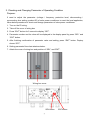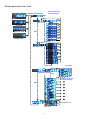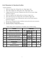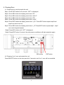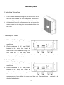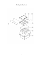
1
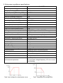
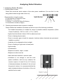
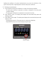
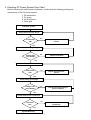
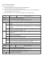
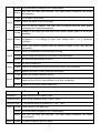
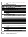
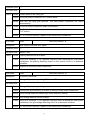
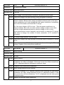
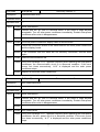
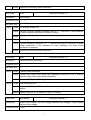
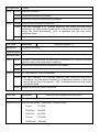
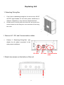
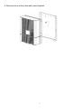
SOLAR POWER CONDITIONER Service Manual JH-1600E Released in May 2009 Version: V00 TABLE OF CONTENTS Important Service Safety Precautions…………………………………………… 2 Warning…………………………………………………………………………….. 3 General Information……………………………………………………………….. 5 1 System Overview.................................................................................................................................. 5 2 Overview of Solar Power Conditioner .............................................................................. 6 3 Solar Power Conditioner Specifications........................................................................... 9 Analyzing Defect Situation………………………………………………………… 10 1 Analyzing Defect Situation................................................................................................ 10 2 Checking PV Power System Flow Chart........................................................................... 12 3 Checking and Changing Parameter of Operating Condition............................................. 13 4 Clearing Error.................................................................................................................... 16 5 Error Code and Service..................................................................................................... 17 Replacing Fuse……………………………………………………………………… 28 1 Detaching Wiring Box........................................................................................................ 28 2 Checking DC Fuse............................................................................................................. 28 3 Checking AC Fuse.............................................................................................................. 28 4 Replacing AC or DC Fuse................................................................................................... 29 Replacing Unit…………………………….…………………………………………. 30 1 Detaching Wiring Box........................................................................................................ 30 2 Remove AC / DC and Communication Cables.................................................................. 30 3 Detach Two Screws on the Bottom of the Unit.................................................................. 30 4 Remove the Unit from the Wall Mount Bracket.................................................................. 31 Checking System Condition after Service…………………………………………. 32 Circuit and electrical block diagram………………………………………………… 33 Replacement Parts List……………………………………………………………… 34 Packing instruction…………………………………………………………………… 37 1 Important Service Safety Precautions This manual contains important safety instructions for JH-16000 E that shall be followed during the installation of the solar power conditioner. To reduce the risk of electrical shock, and to ensure the safe installation and operation of the solar power conditioner, the following words appear throughout this manual to inform you or alert you something may cause dangerous situation or safety instructions must be followed. 2 WARNING These servicing instructions are for user by qualified personnel only. To reduce the risk of electrical shock, do not perform any servicing other than that specified in the operating instructions unless you are qualified to do so. Be sure to use appropriate service parts listed in the replacement parts list and tools when you repair the solar power conditioner. Never alter the solar power conditioner as it may cause an electrical shock, heat or fire. If you have to take the solar power conditioner to be repaired, be sure to turn off AC and DC input breaker for the solar power conditioner on the load center in advance. Otherwise, it may cause an electrical shock. Be sure to confirm that the inside of the solar power conditioner is not in high temperature before repairing. Otherwise, it may cause burn. PV module always supplies the DC voltage of 60V to 350V on daytime (particularly sunny day). Be careful when treating the cable from the PV module. Otherwise, it may cause an electrical shock. Do not repair the solar power conditioner with wet hands. Otherwise, it may cause an electrical shock. Make sure to be earthen if the solar power conditioner is repaired in wet place. Otherwise, it may cause an electrical shock. Be sure not to touch the live parts when you repair the solar power conditioner. Do not water electrical components of the solar power conditioner. Otherwise, it may cause an electrical shock. Be sure to stop the operation of the solar power conditioner and turn off breakers when you clean the solar power conditioner. If you move the solar power conditioner, be sure to follow the instructions on the “INSTALLATION & OPERATION MANUAL” for the relevant model. If the wall on which the solar power conditioner is installed is weak or the solar power conditioner is improperly installed, it may fall and cause injury. 3 Cables should not be damaged or assembled. Do not use cables or lead wires with scar or deteriorated ones. Replace them with appropriate one immediately. Otherwise, it may cause an electrical shock or fire. Be sure to confirm the location applied for a part, wiring, soldering or the connection status of crimping terminal, are all appropriate. Otherwise, it may cause heat, fire or an electrical shock. If mounting structure or mounting components are deteriorated, such as corroded, replace them with new ones. Otherwise, it may fall down and cause injury. Be sure to check grounding status and set it appropriately. Otherwise, it may cause an electrical shock. Never apply the voltage of more than 350V, which is the maximum system voltage of the solar power conditioner. 4 General Information 1. System overview Item Function Description 1 PV module Convert solar energy to electric power 2 Mounting Fix the PV module on the roof with mounting structure structure. DC Wiring Connect PV array to DC breaker 3 cable Remark PV: photovoltaic PV array: A number of PV modules connected together in a single mounting structure 4 DC breaker Isolate the PV array from solar power conditioner. 5 Solar power The solar power conditioner converts DC conditioner power generated by PV array into AC power, and automatically controls the operation of system. 6 AC breaker Isolate AC power from solar power conditioner. 5 2. Overview of solar power conditioner Unit: mm Fig1. Dimension of solar power conditioner 6 Unit: mm Fig2. Dimension of bracket Fig3. Terminal of solar power conditioner 7 Table1. Mechanical specification JH-1600E Outdoor enclosure Main body IP65 Wiring box IP55 Dimensions - without wall mount 440*348*141 mm (H*W*D / mm) Dimensions - with wall mount 440*348*153 mm (H*W*D / mm) Shipping dimension (H*W*D / mm) 515*450*290 mm Inverter weight 13 kg Shipping weight 18 kg Input connection From#16 to #10 AWG Output connection From#16 to #10 AWG 8 3. Solar power conditioner specifications Model JH-1600E Maximum system voltage 350 V Rating input voltage (DC) 240 V Range of operating DC voltage(DC) 60~320 V Maximum array short circuit current(DC) 10A Maximum operating current(DC) 8.5A Nominal output voltage(AC) 230 V Operating voltage range(AC) 210 – 255 V Nominal output frequency(AC) 50 Hz Operating frequency range(AC) 47 – 53 Hz Maximum continuous output current(AC) 7.6 A Output over-current protection(AC) 10 A Maximum continuous output power(AC) 1600 W(DC input 200 – 320 VDC) Power Factor >0.95 ( more than rated output power1/8 ) Total Current Harmonic Distortion < 5% Operating temperature range -20 Dimensions - without wall mount 440*348*141 mm Dimensions - with wall mount 440*348*153 mm inverter weight 13 kg Shipping weight 18 kg ~ 60 (derating at 40 ~ 60 ) Main Circuit System Solar power conditioner system Voltage stiff current control system Switching system PWM(pulse width modulation)system Insulation Built-in high frequency insulation Electric system 1-phase 2-wire system Protection Input/Output fuses Grid-connected protection AC over/under voltage/frequency, AC over current Anti-islanding Fig5. Temperature de-rating curve Fig4. Input voltage for output power curve. 9 Analyzing Defect Situation 1. Analyzing Defect Situation I. Checking serial number Check and record the serial number of the solar power conditioner (You can find it in the rating label located at right side of the unit). Representation of serial number: A. Last number of Production Year. B. Month (0 ~ 9, X, Y, Z) C. Factory: 7 for DELTA China WJ factory D. Consecutive number (5 digits) a b c d II. Checking environment where system is installed Check whether the installation site does not fall into none of the following conditions: The ambient temperature is outside the range of tolerable ambient temperature (Solar Power Conditioner; -20°C to +60°C, -4°F to +140°F). Higher than the altitude of about 2,000 m above sea level Prone to damage by sea water Close to corrosive gas or liquid (for example, locations where chemicals are processed, feedlots or poultry) Avoid the unit to exposed to direct sunlight Prone to flooding or high levels of snow pack High humidity ․Condensation ․Exposure to steam, vapor, or water ․Exposure to direct cool air ․Near television antenna or antenna cable ․Ventilation is not enough to cool the solar power conditioner, that is to say, outdoors, the inverter requires. At least 50 cm (19.7 inches) of clearance between the button of the unit and the ground, indoors, it is recommended that the same clearance between the button of the unit and the floor be used. 10 Installing the conditioner in the place mentioned above may cause the malfunction of the system caused by water or high temperature inside the solar power conditioner. III. Checking accumulated power A. Check whether the solar power conditioner is in either of the following conditions. The solar power conditioner is powered on (Indicator is displayed on the solar power conditioner display). The solar power conditioner is not powered, but connected to the utility. B. Press SELECT button. The display panel displays the accumulated daily power with displaying “Wh/D”. C. Press SELECT button again. The display panel displays the accumulated total power with displaying “kWh”. No pressing any button for 10 seconds returns to output power displaying. Press SELECT button to turn on the backlight during the night. SELECT button 11 2. Checking PV Power System Flow Chart Before checking the solar power conditioner, confirm that the following setting and connections of the PV power system: 1. DC disconnect 2. PV string 3. AC disconnect 4. Utility grid Check PV system Check DC disconnect device Connection OK? NO Repair DC disconnect device YES Check PV string Voltage Voltage OK? (60~120Vdc) NO Repair PV module YES Check AC disconnect device NO Connection OK? Repair AC disconnect device YES Check utility grid voltage Voltage OK? (210~250Vac) NO Ask about normal utility to power company YES Check Solar Power Conditioner Operation OK? NO Repair solar power conditioner YES System Recovery 12 3. Checking and Changing Parameter of Operating Condition Purpose: If need to adjust the parameter (voltage / frequency protection level, disconnecting / reconnecting time setting, product ID) of solar power conditioner to meet the local application, follow below procedures to check and change parameters of solar power conditioner. 1. Turn on the PV string. 2. Take off the cover of wiring box 3. Press “ENT” button for 5 second to display “OFF”. 4. Parameter number and its value will be displayed in the display panel by press “SEL” and “ENT” button. 5. After finishing confirmation of parameter value and setting, press “ENT” button. Display shows “OFF“. 6. Setting parameter flow chart attaches below. 7. Attach the cover of wiring box and position of “SEL” and “ENT”. Wiring box cover SEL button 13 ENT button Setting parameter flow chart Please refer to the Error/Fault code Push 'ENT' for 5 seconds SEL MPPT mode ENT Error List Fault mode Night time mode SEL Standby mode ENT SEL ENT SEL ENT SEL ENT SEL ENT SEL ENT SEL ENT SEL ENT ENT ENT Day Power List ENT ENT ENT ENT Changed ENT ENT SEL Parameters Setting SEL SEL ENT SEL SEL Please refer to the software Setting ● SEL SEL ● SEL ● SEL SEL ● SEL ● SEL ● SEL ● ENT SEL SEL 14 Reset Error List ENT List of Parameters for Operating Condition Function explanation: 1. Utility over voltage (Vac): Setting utility over voltage trigger value. 2. Utility under voltage (Vac): Setting utility under voltage trigger value. 3. Voltage abnormal trip time (sec): Setting trip time when over and under voltage protection is triggered. 4. Utility over frequency (Hz): Setting utility over frequency trigger value. 5. Utility under frequency (Hz): Setting utility under frequency trigger value. 6. Freq. abnormal trip time (sec): Setting trip time when over and under frequency protection is triggered. 7. Recover timer: Setting solar power conditioner recovery time when error occurrence. 8. RJ-45 ID: Setting RJ-45 ID number. 9. Operation frequency: Setting utility frequency. Table2. Setting value and parameter (The shadow value is default setting.) Item Function Parameters 1 Utility over voltage (Vac) 250 255 260 2 Utility under voltage (Vac) 205 210 215 3 Voltage abnormal trip time (sec) 1 1.4 1.8 4 Utility over frequency (Hz) 52 53 54 5 Utility under frequency (Hz) 46 47 48 6 Freq. abnormal trip time (sec) 1 1.4 1.8 7 Recover timer 10 60 150 300 8 RJ-45 ID 5 6 …… 31 9 Operation frequency 50 60 15 4. Clearing Error 4.1 Clearing error code list inside the unit Step1: Press ENT button for 5 seconds. “OFF” is displayed. Step2: Press SEL button the display panel show “EL”. Step3: Press SEL button the display panel show “dAY-P”. Step4: Press SEL button the display panel show “PS”. Step5: Press SEL button the display panel show “d-rSL”. Step6: Press ENT button the display panel show “r_EL”.Press ENT button repeat step5 and step6 can reset error list. Step7: Press SEL button the display panel show “r_IP”.Press ENT button repeat step5 ~ step7 can reset integrated power. Step8: Press SEL button until “OFF” is displayed. Step9: Press ENT button 5 second, the solar power conditioner will start operation again. SEL button ENT button 4.2 Clearing “d-xx” error and restart the unit Press SELECT button on the front panel for 5 seconds, and “d-xx” error will be cancelled. 16 5. Error Code and Service Recovery method explanation: I. Recovery method A: Auto-restart after default reconnecting time. II. Recovery method B: Auto-restart after waiting 10 sec. III. Recovery method C: Auto-restart after waiting 10 sec. But enter recovery method D when error four times (show d-XX error code.) IV. Recovery method D: Turn on solar power conditioner by hand after repaired. Error code F-00 Recovery method : A Description Utility voltage over setting parameter Protection level Over 255V(default value) [Parametr:250V / 255V / 260V] Activation time 1 sec(default value) [Parametr:1S / 1.4S / 1.8S] Case.1 Cause Voltage of the utility grid rises due to the electric supply status of the power company. Check Measure the receiving voltage at the output terminal of the solar power conditioner. If L-N is 255V (in case of preset value) or more, it is in abnormal condition. Action Change the parameter setting to a higher level, and make sure the utility voltage is low enough than setting value. Case.2 Cause Output impedance is too large to make the output terminal voltage is over setting value. Check Check the impedance between inverter and the grid, and the cable loss can not be over 1% of full power. Action Make the impedance as short as you can. Case.3 Cause Grid voltage detector circuit is failed. Check Check the voltage of receiving utility voltage, if its voltage is large than 210 and fuse is fine, some problem is inside the solar conditioner. Action Replace a new solar power conditioner. Error code F-01 Recovery method : A Contents Utility voltage under setting parameter Protection level Less 210V(default value) [Parametr:205V / 210V / 215V] Activation time 1 sec(default value) [Parametr:1S / 1.4S / 1.8S] Case.1 Cause Power failure of the utility grid. 17 Check The solar power conditioner is in normal status. Action Wait until the utility grid recovers. The solar power conditioner will restart automatically. Cause AC breaker is shut down. Case.2 Check Check the status of the AC breaker. Action Turn on the AC beaker. The utility grid is received and the solar power conditioner will restart automatically. Cause Voltage of the utility grid falls due to the electric supply status of the power company. Measure the receiving voltage at the output terminal of the solar power Case.3 Check conditioner. If L-N voltage is lower than setting value, it is in abnormal condition. Action Inform your power company that the sending voltage is low, and ask the adjustment. Cause Defect or looseness of the terminals or wiring Case.4 Check Check wiring and terminal of the CNW7 in the wiring box. Action Re-wiring on the terminal of CNW7. Cause AC fuse is blown out. Case.5 Check Check the resistance of fuse (FUW2) with meter in the wiring box. Action Replace the fuse (FUW2) inside the wiring box. Cause Defect grid voltage detector circuitry Case.6 Check Action Check the voltage of receiving utility voltage, if its voltage is large than setting value and fuse is fine, some problem is in solar conditioner. Replace a new solar power conditioner. Error code F-02 Recovery method : A Description Utility frequency over setting value Protection level Over 53 Hz [Parametr:52Hz / 53Hz / 54Hz] Activation time 1 sec(default value) [Parametr:1S / 1.4S / 1.8S] Case.1 Cause Power failure of the utility grid. Check The solar power conditioner is in normal status. Action Wait until the utility grid recovers. The solar power conditioner will restart automatically. Case.2 Cause Frequency detector circuit is failed. 18 Check If the error message “F-02” appears frequently after restarting the solar power conditioner, the frequency detecting circuit on the control circuit is in abnormal condition. Action Replace a new solar power conditioner. Error code F-03 Recovery method : A Description Utility frequency under setting value Protection level Less 47Hz [Parametr:46Hz / 47Hz / 48Hz] Activation time 1 sec(default value) [Parametr:1S / 1.4S / 1.8S] Case.1 Cause Power failure of the utility grid. Check The solar power conditioner is in normal status. Action Wait until the utility grid recovers. The solar power conditioner will restart automatically. Case.2 Cause Frequency detector circuit is failed. Check If the error message “F-03” appears frequently after restarting the solar power conditioner, the frequency detecting circuit on the control circuit is in abnormal condition. Action Replace a new solar power conditioner. Error code F-06 Recovery method : B Description Anti-islanding protection (frequency over) Protection level --- Activation time --- Case.1 Cause Power failure of the utility grid. Check The solar power conditioner is in normal status. Action Wait until the utility grid recovers. The solar power conditioner will restart automatically. Case.2 Cause The solar power conditioner stops unnecessary. Check Confirm that the solar power conditioner restarts, and check the status when F-06 occurs. Action If F-06 occurs frequently, replace a new solar power conditioner. Error code F-07 Recovery method : B Description Anti-islanding protection (frequency under) 19 Protection level --- Activation time --- Case.1 Cause Power failure of the utility grid. Check The solar power conditioner is in normal status. Action Wait until the utility grid recovers. The solar power conditioner will restart automatically. Case.2 Cause The solar power conditioner stops unnecessary. Check Confirm that the solar power conditioner restarts, and check the status when F-07 occurs. Action If F-07 occurs frequently, replace a new solar power conditioner. Error code F-08 Recovery method : B Description Miss utility synchronal lock signal Protection level --- Activation time Within 1 sec. Case.1 Cause Polarity detector circuit is failed. Check If the error message “F-08” appears frequently after restarting the solar power conditioner, the polarity detecting circuit on the control circuit is in abnormal condition. Action Replace a new solar power conditioner. Error code F-09 Description Frequency abnormal Protection level Wrong utility frequency setting (50Hz <--> 60Hz). Activation time Recovery method : B --- Case.1 Cause Wrong utility frequency setting Check Confirm the grid frequency is correct in setting of solar power conditioner. Action Enter setting mode and choice right utility frequency setting. Case.2 Cause Grid voltage detector circuit is failed. Check If the error message “F-09” appears frequently after re-setting the solar power conditioner, the grid voltage detecting circuit is in abnormal condition. Action If F-09 occurs frequently, replace a new solar power conditioner. 20 Error code P-11 Description PV array over voltage Protection level More than 320VDC Activation time Recovery method : B 200 mS Case.1 Cause Input voltage of the solar power conditioner exceeds the limited value. Check Check the voltage of all input terminal of the solar power conditioner. Action (1) If the input voltage is large than 350V. --The solar power conditioner is in normal condition. But the input voltage exceeds the allowed value of the solar power conditioner and it may damage the solar power conditioner. Immediately turn off the DC breaker and check the PV strings. (2) If the input voltage is 350V or less. --The solar power conditioner is in normal condition. But it will not restart until the voltage is 320V or less. Wait until the sunlight radiates decrease so that the voltage is 320V or less. If such phenomenon occurs frequently, ask the dealer to check the PV strings. And study to change the number of series connection of PV modules in necessary. Case.2 Cause PV array voltage detector circuit is failed. Check Check the voltage of all input terminal of the solar power conditioner is correct of not. Action If the error message “P-11” appears frequently after confirming the PV array voltage. Replace a new solar power conditioner. Error code E-15 (d-15) Description Relay sticking Protection level --- Activation time 2.4 Sec. Recovery method : C Case.1 Cause Relay is failure. Check If the error message “E-15” appears frequently after re-setting the solar power conditioner, the relay is damaged. If this error occurs four times successively, “d-15” is displayed and the solar power conditioner stops. Action Replace a new solar power conditioner. Case.2 Cause Relay voltage detector circuit is failed. Check If the error message “E-15” appears frequently after restarting the solar power conditioner, the relay voltage detecting circuit is in abnormal condition. If this error occurs four times successively, “d-15” is displayed and the solar power conditioner stops. Action Replace a new solar power conditioner. 21 Error code E-16 (d-16) Description Communication error. Protection level --- Activation time --- Recovery method : C Case.1 Cause Noise interference Check Confirm that the AC and PV terminal noise. If the noise is large beyond acceptable. Turn off solar power conditioner immediately. Restart solar power conditioner after noise is disappearance. Action --- Case.2 Cause The solar power conditioner display cable is disconnected. Check Check the connection status of the cable between the solar power conditioner and the display board. Action If the connector and the cable are not securely connected, connect them again. Case.3 Cause Internal communications fail. Check If the error message “E-16” appears frequently after restarting the solar power conditioner, the communication circuit is in abnormal condition. If this error occurs four times successively, “d-16” is displayed and the solar power conditioner stops. Action Replace a new solar power conditioner. Error code E-17 (d-17) Description Aux. power abnormal Protection level --- Activation time --- Recovery method : C Case.1 Cause Noise interference Check Confirm that the AC and PV terminal noise. If the noise is large beyond acceptable. Turn off solar power conditioner immediately. Restart solar power conditioner after noise is disappearance. Action --- Case.2 Cause Aux. power failed Check If the error message “E-17” appears frequently after restarting the solar power conditioner, the aux. power circuit is in abnormal condition. If this error occurs four times successively, “d-17” is displayed and the solar power conditioner stops. 22 Action Replace a new solar power conditioner. Error code E-18 Description Ground fault. Protection level --- Activation time --- Recovery method : B Case.1 Cause PV array grounding fail. Check Confirm PV array resistance between the PV + / - and GND. If the resistance is lower 640Kohm, ask dealer to check PV array. Action --- Case.2 Cause Grounding test circuits fail. Check Confirm resistance between PV + / - terminal and GND in wiring box of solar power conditioner. If the resistance is lower 640kohm, the solar power conditioner is damage. Action Replace a new solar power conditioner. Error code d-20 Description Temperature sensor broken. Protection level --- Activation time --- Recovery method : D Case.1 Cause CNW5/CNW6 disconnect. Check Confirm that CNW5 and CNW6 are connecting correctly or not. If loosely, connect it and restart solar power conditioner. Action Connect CNW5 and CNW6 tightly. Case.2 Cause Thermal fuse broken. Check Measure CNW5 and CNW6 resistance is open or not. If open, thermal fuse broken. Action Replace new AC or DC terminal. (CNW7 or CNW9) Error code E-21 (d-21) Description Output over current / DC bus voltage transient over voltage / Utility voltage transient over voltage Protection level Recovery method : C 9.5A 23 Activation time 300ms Case.1 Cause Bad utility waveform Check Check the waveform of the utility. Action Avoid the interference on the utility waveform. Case.2 Cause Defect of the solar power conditioner. Check If the error message “E-21” appears frequently after restart the solar power conditioner, the solar power conditioner is in abnormal condition. If this error occurs four times successively, “d-21” is displayed and the solar power conditioner stops. Action Replace a new solar power conditioner. Error code E-22(d-22) Description DC offset over rating Protection level --- Activation time --- Recovery method : C Case.1 Cause Caused by load used near the solar power conditioner, DC (75mA) is included with the output of the solar power conditioner. Check Confirm that the solar power conditioner and restarts. Action --- Case.2 Cause DC offset detector circuit is abnormal. Check If the error message “E-22” appears frequently after restart the solar power conditioner, the solar power conditioner is in abnormal condition. If this error occurs eighty times successively, “d-22” is displayed and the solar power conditioner stops. Action Replace a new solar power conditioner. Error code E-23(d-23) Recovery when temperature under spec. Description Fin high temperature Protection level (Start de-rating temp. / stop temp. / recovery temp.) Choke : 71/75/69 D2d 200V : 78/81/58 D2d 320V : 69/72/58 Inverter : 72/74/58 DSP board : 80/84/58 24 Activation time --- Case.1 Cause Ambient over spec. Check Measure the ambient, if over 60C than solar power conditioner stops. Action Waiting for ambient decrease. Case.2 Cause The solar power conditioner is located in inappropriate location. Check Obstruction around the solar power conditioner may cover the enclosure of solar power conditioner for admission/evacuation. Action Remove the obstruction. Case.3 Cause The temperature of fin is over spec. (see above “protection level” item for detail.) Check Check the temperature of fin. If over spec. than solar power conditioner stops. Action Waiting for temperature decrease. Case.4 Cause Fin temperature detector circuit is abnormal. Check Check the temperature of fin. If low, than restart it. If the error message “E-23” appears frequently after restart the solar power conditioner, the solar power conditioner is in abnormal condition. If this error occurs four times successively, “d-23” is displayed and the solar power conditioner stops. Action Replace a new solar power conditioner. Error code E-26(d-26) Recovery method : C Description DC/DC converter abnormal Protection level --- Activation time --- Case.1 Cause The setting of gain parameters is wrong. Check Check the voltage, current, and power value of AC output and DC input between display and power meter. If difference, re-calibration again. Action Replace a new solar power conditioner. Case.2 Cause DC/DC converter is damage. Check Check the efficiency of solar power conditioner. If small 70%, than DC/DC converter is damage. If the error message “E-26” appears frequently after restart the solar power conditioner, the solar power conditioner is in abnormal condition. If this error occurs four times successively, “d-26” is displayed and the solar power conditioner stops. Action Replace a new solar power conditioner. 25 Error code E-27(D-27) Description Relay open Protection level --- Activation time --- Recovery method : C Case.1 Cause Relay is damage. Check If the error message “E-27” appears frequently after restart the solar power conditioner, the solar power conditioner is in abnormal condition. If this error occurs four times successively, “d-27” is displayed and the solar power conditioner stops. Action Replace a new solar power conditioner. Case.2 Cause Relay detector circuit is abnormal. Check If the error message “E-27” appears frequently after restart the solar power conditioner, the solar power conditioner is in abnormal condition. If this error occurs four times successively, “d-27” is displayed and the solar power conditioner stops. Action Replace a new solar power conditioner. Error code E-28 Description DC bus voltage abnormal. Protection level --- Activation time --- Recovery method : C Case.1 Cause Noise interference Check Confirm that the AC and PV terminal noise. If the noise is large beyond acceptable. Action Turn off solar power conditioner immediately. Restart solar power conditioner after noise is disappearance. Case.2 Cause DC bus voltage detector circuit or boost stage circuit is failed. Check Check the voltage of all input terminal of the solar power conditioner is correct or not. If the error message “E-28” appears frequently after confirming the PV array voltage. The solar power conditioner is damaged. Action Error code Replace a new solar power conditioner. Recovery method : D d-40 26 Description EEPROM abnormal. Protection level -- Activation time -- Case.1 Cause EEPROM failed. Check If the error message “D-40” appears frequently after confirming the PV array voltage. The solar power conditioner is damaged. Action Replace a new display board. 27 Replacing Fuse 1. Detaching Wiring Box I. If you have to detaching wiring box, be sure to turn off AC and DC input breaker for the solar power conditioner in advance. Otherwise, it may cause an electrical shock. II. Confirm the DC and AC power are turned off, and remove four screws located on the wiring box cover and take off the wiring box cover. 2. Checking DC Fuse I. Perform “1. Detaching Wiring Box”, and remove the wiring box cover of the conditioner. II. Check resistance of DC fuse (FUW1) located in the wiring box board by multi-meter. If the resistance is huge, DC fuse blew out. In this case, other components may have defect to cause fuse blow out. The solar power conditioner is required to be checked in the factory. 3. Checking AC Fuse I. Perform “1. Detaching Wiring Box”, and remove the wiring box cover of the conditioner. II. Check resistance of AC fuse (FUW2) located in the wiring box board by multimeter. If the resistance is huge, AC Fuse blew out. In this case, some component may have defect to cause fuse blow out. The conditioner is required to be checked in the factory. 28 4. Replacing AC or DC Fuse I. Perform “1. Detaching Wiring Box”, and remove the wiring box cover of the conditioner. II. Remove the AC fuse from the holder. III. Remove the DC fuse from the holder. IV. Insert a new AC fuse (FUW2) into the holder. (little fuse : 20A/250V) V. Insert a new DC fuse (FUW1) into the holder. (little fuse : 15A/600V) 29 Replacing Unit 1. Detaching Wiring Box I. If you have to detaching wiring box, be sure to turn off AC and DC input breaker for the solar power conditioner in advance. Otherwise, it may cause an electrical shock. II. Confirm the DC and AC power are turned off, and remove four screws located on the wiring box cover and take off the wiring box cover. 2. Remove AC / DC and Communication cables I. Perform “1. Detaching Wiring Box”, and detach the all cables connected to the solar power conditioner. DC cable 3. Detach two screws on the bottom of the unit 30 AC cable Communication cable 4. Remove the unit from the wall mount bracket 31 Checking System Condition after Service 1. Checking DC input I. Confirm that DC and AC power breaker are turned off. If they are turned on, turn off them. II. Remove the wiring box cover of the solar power conditioner. III. Measure the voltage of PV string on the input side of the DC breaker. If the PV voltage is more than 70V, turn on the DC breaker. If the PV voltage is less than 70V, check the PV modules DC breaker, and DC cable. IV. Measure the DC terminal voltage in the wiring box, and confirm that it is more than 70V. If the terminal voltage of the DC input more than 70V: The solar power conditioner is starting. If the terminal voltage of the DC input is less than 60V: The solar power conditioner is stopped. 2. Checking solar power conditioner display Check the status of the solar power conditioner display. (DC input voltage is more than 70V.) Error code “F-01” displayed: It is right because the AC power breaker is turned off. No displayed: The display of solar power conditioner or its cable fail. 3. Checking contents of solar power conditioner display Check all parameters setting of solar power conditioner. If “OFF ” is displayed: Press “ENT” button for more than 5 seconds in the wiring box, and confirm display shows “F-01” instead of “OFF”. It means that DC status is OK. 4. Checking AC I. Turn off DC breaker. II. Turn on AC breaker. III. Checking utility voltage on the AC terminal block in the wiring box, the utility voltage must be between 210 VAC and 255 VAC (depending on parameters setting). If the voltage is different, check the utility cable. 5. Confirming operation I. Turn on the DC breaker and AC breaker. II. Check the display of the solar power conditioner. If “0” and green LED twinkle are displayed after 150 seconds countdown, all the status is OK. The solar power conditioner is running after count down. 32 Circuit and electrical block diagram Item Function 1 DC EMI 2 Boost 3 Full bridge Description To prevent conduction noise out from DC cable. To regular DC voltage for inverter stage. Using four MOSFETs as switch to inverter DC voltage to AC voltage. 4 Driver board 5 Spike killer Generator driver signal of full bridge for MOSFETs. To kill the spike voltage of inverter diodes for protection purpose. board 6 Inverter switch 7 AC EMI 8 Control board To control all circuit operation under desire. 9 Junction box Including AC terminal, DC terminal, AC fuse, DC fuse, and (wiring box) parameter setting button. 10 Using four MOSFETs as switch to adjust the polarity of AC voltage. To prevent conduction noise out from AC cable. Communication 1. As a communication bridge between control board and user and display board (through RJ-45 connector). 2 Display operation status and information. 33 Replacement Parts List Item Parts Code Description Quantity (1) 9NK0813221802 AC fuse 1 (2) 9NK0891040102 DC fuse 1 (3) 9NK3071538194 Terminal block(DC) 1 (4) 9NK3071539594 Terminal block(AC) 1 (5) 9NK3262043000 Shock Hazard warning label 1 (6) 9NK3470343100 AC/DC Gland 2 (7) 9NK3470343200 RJ45 Gland 2 (8) 9NK3312387700 Wiring box front cover 1 (9) 9NK3263048200 Label for wiring box front cover (upper side) 1 34 Item Parts Code Description Quantity (10) 9NK3103381000 Screw for wiring box front cover 4 (11) 9NK3105299000 Screw for main body 38 (12) 9NK3263876000 Rating label 1 (13) 9NK3262043100 Burn Hazard warning label 1 35 Item Parts Code Description Quantity (101) (102) 9NK35136666XX Carton 511*445*295mm 1 9NK35188380XX Bottom end block EPE 1 (103) 9NK35009554XX Bag PE 1 (104) 9NK35188379XX Top end block EPE 1 Item Parts Code Description Quantity (105) (106) 9NK33123936XX Wall mounting bracket 1 9NK31033810XX Screw M#6-32*10 (Fix unit to the bracket) 2 (107) 9NK31090374XX Screw ψ5.5*1.8*80 (Fix bracket to the wall) 10 (108) 9NK50113648XX Installation & Operation Manual 1 36 Packing instruction 37 38