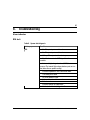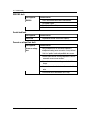
1
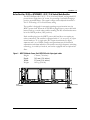
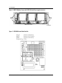
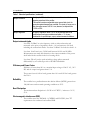
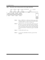
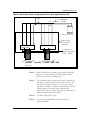
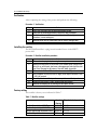
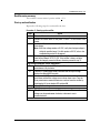
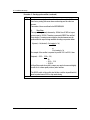
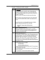
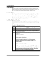
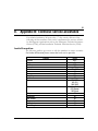
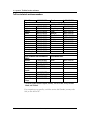
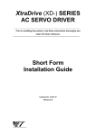
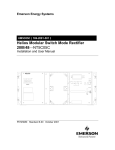
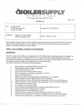
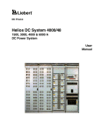
Astec Advanced Power Systems UM5C06D ( 169-2071-504 ) Helios Rectifier 25/48 Single Phase -48V, 25 A Power Factor Corrected Switch Mode Rectifier NT5C06D Installation and User Manual P0831010 Standard 7.00 May 2001 Astec Advanced Power Systems A part of Emerson Network Power Astec Advanced Power Systems Helios Rectifier 25/48 Single Phase -48V, 25A Power Factor Corrected Switch Mode Rectifier NT5C06D Installation and User Manual Manual Number : UM5C06D ( 169-2071-504 ) Manual Status : Standard Manual Issue : 7.00 Release Date : May 2001 P0831010 Copyright 2001 Astec Advanced Power Systems Ltd All Rights Reserved Published in Canada The information contained in this manual is the property of Astec Advanced Power Systems and is subject to change without notice. Astec Advanced Power Systems Ltd reserves the right to make changes in design or components as progress in engineering and manufacturing may warrant. Except as specifically authorized in writing by the V.P. of Engineering and Product Manufacturing of Astec Advanced Power Systems Ltd, the holder of this manual shall keep all information contained herein confidential and shall protect same, in whole or in part, from disclosure and dissemination to all third parties, and use the same for start-up, operation, troubleshooting, and maintenance purposes only. Any modification to the equipment must be approved by the person responsible for product safety, and design quality at Astec Advanced Power Systems Ltd to ensure that the equipment complies with the operation standards. This equipment generates, uses, and can radiate radio frequency energy, and if not installed and used in accordance with the instructions contained in the Installation and User Manuals, can cause harmful interference to radio communications. Operation of this equipment in a residential area is likely to cause harmful interference, in which case the user will be required to correct the interference at his own expense. Astec Advanced Power Systems A part of Emerson Network Power Helios Candeo is a trademark of Astec International Ltd. The Emerson logo is a trademark and service mark of Emerson Electric Co. Helios Rectifier 25/48NT5C06D Installation and User Manual 5 Publication history May 2001 Standard issue 7.00. Manual modified to reflect the Emerson identity. ( EC 102-26438 ) September 1999 Standard 6.0. Document modified to be in accordance with Astec standards. (ECN 102-17331) May 1999 Standard 5.0. Document modified to reflect Astec identity. Figure 11 modified. (ECN 102-14852) March 1997 Std. release 4.0. New Float Voltage and Current Limit Factory Setting. August 1996 Std. release 3.0. Removal of extended temperature rectifier models Table 1 and Table 6 (note) revised. February 1996 Std. release 2.0. This issue is to cover the revision of “Installation and Start-Up” procedures and Figures 1, 2, 3, 7 and 9 November 1995 Standard release 1.0. Helios Rectifier 25/48NT5C06D Installation and User Manual 6 Publication history This page is left blank intentionally. UM5C06D ( 169-2071-504 ) P0831010 Standard 7.00 May 2001 7 Contents Introduction.............................................................................................................. 11 Description.................................................................................................... 11 Applications .................................................................................................. 12 Equipment Identification .................................................................................. 12 MPS75 NT5C10C(X) power shelf (23-inch) .....................................................12 Helios Rectifier 25/48 NT5C06D(X) –48 V / 25 A Switch Mode Rectifier........13 Specifications .......................................................................................................... 15 Electrical specifications................................................................................... 15 Output noise and ripple .........................................................................................16 Efficiency and Power Factor .................................................................................16 Reliability..............................................................................................................16 Heat Dissipation ...................................................................................................16 Electromagnetic interference (EMI) .......................................................................16 Environmental specifications ............................................................................ 17 Operating..............................................................................................................17 Transportation......................................................................................................17 Storage.................................................................................................................17 Installation and start up.......................................................................................... 19 Tools and test equipment................................................................................. 19 Installing the power shelf................................................................................. 19 Wiring the power shelf..........................................................................................20 Installing the AC power.........................................................................................21 DC Conductors Installation ...................................................................................22 Control and Alarm Connections .............................................................................23 Verification ...........................................................................................................28 Installing the rectifier...................................................................................... 28 Factory setting .....................................................................................................28 Rectifier meter accuracy.......................................................................................29 Start-up and verification .......................................................................................29 Slope Load Share ..................................................................................................32 Helios Rectifier 25/48NT5C06D Installation and User Manual 8 Contents Forced Load Share ................................................................................................32 Load Share Adjustment Procedure ........................................................................32 Operation.................................................................................................................. 33 Front panel controls........................................................................................ 34 Features ....................................................................................................... 34 Local float / equalize control .................................................................................34 High voltage shutdown (HVSD) - local ...................................................................34 High voltage shutdown - remote............................................................................34 Start-up delay.......................................................................................................35 Test points (V+, V-) ..............................................................................................35 Indicators .............................................................................................................35 Rectifier failure alarm (RFA)..................................................................................35 Fan failure alarm...................................................................................................35 Internal high voltage shutdown (HVSD) .................................................................35 Local ON/OFF control (AC breaker)........................................................................36 Remote ON/OFF control ........................................................................................36 Remote voltage sensing ........................................................................................36 Sense fail alarm (SEN FAIL)...................................................................................36 Current limiting .....................................................................................................36 Soft start / walk-in ...............................................................................................36 AC inrush current..................................................................................................36 Sequential start ....................................................................................................37 Parallel operation..................................................................................................37 Discharge of output capacitors .............................................................................37 Input AC voltage monitor ......................................................................................38 Thermal shutdown ................................................................................................38 Remote high voltage shutdown .............................................................................38 Local / remote high voltage shutdown reset ..........................................................38 Remote equalize control........................................................................................38 Power interface edge connector............................................................................38 Signal interface connector ............................................................................... 39 Maintenance............................................................................................................. 41 Float / equalize............................................................................................... 41 High voltage shutdown (HVSD) ......................................................................... 42 Cooling fan.................................................................................................... 42 Fan replacement ...................................................................................................43 Power shelf................................................................................................... 45 Troubleshooting ....................................................................................................... 47 Alarm indication............................................................................................. 47 UM5C06D ( 169-2071-504 ) P0831010 Standard 7.00 May 2001 Contents 9 RFA fault ..............................................................................................................47 SEN FAIL fault ......................................................................................................48 Erratic load fault...................................................................................................48 Current or voltage float fault ................................................................................48 Appendix A: Replacement parts.............................................................................. 49 Appendix B: Technical service assistance ............................................................. 51 Local toll-free prefixes .................................................................................................51 Toll-free technical assistance numbers.........................................................................52 List of terms and acronyms..................................................................................... 53 List of Figures Figure 1 - MPS75 Modular Power Shelf-NT5C10C with 8-pin signal cables .................13 Figure 2 - MPS75 Modular Power shelf- NT5C10C with 26-pin signal connectors........14 Figure 3 - NT5C06D Switch Mode Rectifier.................................................................14 Figure 4 - Power shelf common AC connection.............................................................21 Figure 5 - Power shelf individual AC connection ...........................................................22 Figure 6 - Connecting the DC power shelf ....................................................................23 Figure 7 - No controller, remote sensing connection for 8-pin signal cable shelves........26 Figure 8 - No controller, remote sensing connection for a 26-pin signal connector shelf ...........................................................................................................27 Figure 9 - NT5C06D - front view..................................................................................34 Figure 10 - Power interface connections......................................................................39 Figure 11 - Control signal connections .........................................................................40 Figure 12 - NT5C06D rear view ...................................................................................44 List of Tables Table 1 - Electrical specifications.................................................................................15 Table 2 - AC cable wire size.........................................................................................21 Table 3 - AC Fuses.......................................................................................................21 Table 4 - DC cable wire size.........................................................................................23 Table 5 - Rectifier and Controller interface connections (8-pin connectors) ..................24 Table 6 - Rectifier and Controller interface connections (26-pin connector) ..................24 Table 7 - Rectifier settings ..........................................................................................28 Table 8 - Indicators......................................................................................................35 Table 9 - System fault diagnosis..................................................................................47 List of Procedures Procedure 1 - Installing the power shelf .......................................................................20 Procedure 2 - Verification ............................................................................................28 Procedure 3 - Rectifier installation procedure...............................................................28 Procedure 4 - Starting up the rectifier..........................................................................29 Procedure 5 - Adjusting the load share.........................................................................32 Procedure 6 - Adjusting the float / equalize ..................................................................41 Procedure 7 - Replacing the fan ...................................................................................43 Helios Rectifier 25/48 Installation and User Manual 10 Contents This page is left blank intentionally. UM5C06D ( 169-2071-504 ) P0831010 Standard 7.00 May 2001 11 1. Introduction Description The NT5C06D Switch Mode Rectifier is rated for 25 A at -48 V DC. This rectifier incorporates AC input power factor correction circuitry, is highly efficient and lightweight (15 lbs.). It is fully connectorized and plugs into a power shelf into which up to three rectifiers can be installed. The rectifier is forced air cooled with air entering from the front and exhausting out the rear of the power shelf. Separate or common AC power feeds are connected to the power shelf to provide power to each rectifier through the back plane connectors. The rectifier requires a single phase AC source at a nominal voltage of 208/240 V AC, 50 or 60 Hz. The AC power can be supplied from a single phase source or a three-phase system connected phase to phase. The rectifier can also be powered from a 380 V AC WYE system connected phase to neutral (that is, 220 V phase-neutral). The negative and positive outputs of each rectifier are connected to two common busses (BAT -48 and BAT RTN +). The power shelf is designed for a typical capacity of 75 A. The design of the rectifiers allows rectifiers located in the same power shelf, or other shelves, which are connected in parallel, to share the load, either by forced load share or by an output negative slope method. The back plane of the power shelf is equipped with two types of signal connectors. One is an eight-pin (male) connector that provides the interface to analog type controllers. The other connector is a twenty-six-pin flat cable (female) type connector compatible with the Helios system family and provides a larger diagnostic capability. Each rectifier provides a variety of monitoring and alarm features such as, rectifier failure alarm, fan fail alarm, ac fail alarm, remote sensing, sense fail alarm, local and remote high voltage shutdown, automatic high voltage shutdown reset, temporary release, remote and local equalize, and remote shunt monitoring. Helios Rectifier 25/48NT5C06D Installation and User Manual 12 Introduction Applications The rectifier is designed to function as the prime source of power for equipment requiring -48 V DC. It will also operate as a battery charger or as a battery replacement (batteryless operation). Its low output noise and good voltage regulation, combined with a 0.01% V coefficient for each degree C of temperature, provides an excellent charging facility to maintain a battery fully charged. The NT5C06D rectifier is designed to operate continuously in a small or large power system. The NT5C06D is compatible with all other Astec rectifiers, and can be interfaced with other commercially available standard (compatible) rectifiers and power plants. The NT5C06DA/DB is designed to operate in temperatures ranging from 0°C to 65°C. Equipment Identification This section contains a description of the major components and available options for the NT5C06D Rectifier, and the MPS75 power shelves. NT5C06DA -48 V / 25 A Switch Mode Rectifier, brown NT5C06DB -48 V / 25 A Switch Mode Rectifier, dolphin grey NT5C10C(X) Rack mount power shelf family, 23” mounting Note: Many shelf models, with different colors and features, are available. MPS75 NT5C10C(X) power shelf (23-inch) The MPS75 is a power shelf that can support up to three NT5C06 rectifiers. The rectifiers plug into the shelf, which provides interconnection points for AC input, DC output, and alarm and control signals. Each power shelf requires either three AC feeds (one for each rectifier) for the individual AC models, or a single AC feed for the three shelf rectifiers for the common AC models. Its output connects to the charge busbar or to the load distribution panel through two cablesbattery and battery return. Each rectifier position has its own connector-terminated alarm and control cable going to the power plant control and monitor unit. UM5C06D ( 169-2071-504 ) P0831010 Standard 7.00 May 2001 Introduction 13 Helios Rectifier 25/48 NT5C06D(X) –48 V / 25 A Switch Mode Rectifier The NT5C06D provides -48 V / 25 A of isolated, filtered, and regulated DC power from a single phase AC source, for powering a load while charging a positive grounded battery. The output voltage can be adjusted from 46.0 to 56.0 V for floating a 23 or 24 cell battery string. The rectifier is designed for automatic precharge upon insertion into the MPS75 power shelf. When the NT5C06D is plugged into a power shelf with battery back-up, or with other rectifiers running, the DC circuit breaker must be in the OPEN position (OFF position). Each rectifier plugs into the MPS75 power shelf and does not require any other connections. The rectifier is equipped with a 13 A, two-pole, AC input circuit breaker; a 35 A, single-pole, DC output circuit breaker; a digital ammeter; and a set of LEDs, switches and potentiometers for threshold adjustments and alarm indication. The rectifier uses high frequency switching technology, is cooled by forced air, and can be equipped with an optional air filter. Figure 1 - -MPS75 Modular Power Shelf-NT5C10C with 8-pin signal cables Height: Depth: Width: Weight: AC Connections 178 mm (7.0 inches) 305 mm (12.0 inches) 533 mm (21.0 inches) 10.5 kg (23.0 lbs) DC Connections Signal Cables to Controller Helios Rectifier 25/48 Installation and User Manual 14 Introduction Figure 2 - MPS75 Modular Power shelf- NT5C10C with 26-pin signal connectors Mounting holes (4) Mounting holes (4) Signal cable connection DC connection Figure 3 - NT5C06D Switch Mode Rectifier Height: 168 mm (6.60 inches) Depth: 260 mm (10.25 inches) Width: 149 mm (5.85 inches) Weight:6.8 kg (15 lbs) EQL FLT FAN HVSD ON RFA DC CC AC CA OUTPUT F1 3MA 250V V+ VSO RTIE UM5C06D ( 169-2071-504 ) P0831010 Standard 7.00 May 2001 LOA D CHARG E MPR25 MPR15 15 2. Specifications Electrical specifications The NT5C06D rectifier operates within the electrical specifications listed in Table 1. (Refer to the Product Specification which can be obtained from the Engineering department of Astec Advanced Power Systems). Table 1 - Electrical specifications Input Voltage Rating: Nominal 208 / 240 V AC single-phase, 47-63 Hz. Input Voltage Range 176 to 264 V AC. Starting range 184 to 260 V AC. When three-phase 208 / 240 V AC source is available to power the MPS75, it is preferable to distribute the rectifiers among the phases. Input Current Rating: 7.5 A nominal at 208 V AC input and -56 V DC, 25 A output. Use RW90 wire (or equivalent) as listed in Table 2. Recommended AC Service Input Fusing: Two slow flow fusePRN type or equivalent, one for each AC line input; or one slow trip circuit breaker for each rectifier, as listed in Table 3. Output Voltage Rating: Float: -46 V DC to -56 V DC Equalize: 0 - 4 V DC over float. Maximum -59.5 V DC. Output Current Rating: 25 A for each rectifier. Input Protection: Two-pole 13 A circuit breaker, opens both lines for 208 / 240 V AC service. continued Helios Rectifier 25/48NT5C06D Installation and User Manual 16 Specifications Table 1 - Electrical specifications ( continued ) Output Protection: A single pole 35 A circuit breaker is connected in series with the negative output lead of the rectifier. The rectifier contains an adjustable output current limit circuit for protection against damage from overloads. This circuit is factory set to limit the output current to 30 A. It can, however, be adjusted from 12.5 A to 30 A. Output Regulation: At point of regulation: within ± 0.5% of the selected value for all specified input and output variations and within ± 1% for any combination of specified input, output, and environmental conditions. Output noise and ripple Less than 22 dBrnC at voice frequency (with or without batteries and measured at the point of regulation) from a 1 A load current to full load, including the current limit mode. Less than 32 dBrnC for loads less than 1 A. Less than 10 mVrms in any 3 kHz band between 10 kHz and 20 MHz. Measurements are made with batteries at the output terminals of the power shelf and with the rectifier in the local sensing mode. Less than 250 mV peak to peak switching voltage spikes measured differentially by an oscilloscope with a 100 MHz bandwidth. Efficiency and Power Factor Efficiency is better than 90% at a nominal input voltage of 240 V AC, -54 V DC and an output load greater than 15 A. The power factor is 0.98 at loads greater than 10 A and 0.99 for loads greater then 20 A. Reliability The rectifier has a predicted mean time before failures (MTBF) greater than 120,000 hours under normal operating conditions at 30°C. Heat Dissipation The maximum heat dissipation is 156 W or 8.87 BTU’s / minute at -56 V / 25 A. Electromagnetic interference (EMI) The rectifier meets the EN50081-1 (CISPR22 and EN55022) class "B" requirements for conducted and radiated EMI. UM5C06D ( 169-2071-504 ) P0831010 Standard 7.00 May 2001 Specifications 17 Environmental specifications Operating CAUTION An airflow clearance must be left at the rear of the shelf. A minimum of three inches is recommended. The rectifier will operate satisfactorily under the following environmental conditions: Temperature Range: 0° to +65° C (32° to 149° F) NT5C06DA/DB equipped without an air filter 0° to +50° C (32° to 122° F) equipped with an air filter Humidity: 0 to 95% RH (non-condensing) Altitude: Sea level to 2100 m (7000 ft.) Transportation During transportation the rectifier can be subjected to the following conditions without sustaining damage: Temperature Range: -55° C (-67° F) for 16 hours +70° C (158° F) dry heat Humidity: 0 to 95% (non-condensing) 4 kPa max. Vibration: 38mm/sec max. (10 to 30 Hz). 610 mm (24 inch) drop when packaged. Storage Pressure: 12 kPa min. (equiv. to 15 000 m altitude). Temp. Shock: -55° to 70°C (-67° to 158°F) (5 cycles) For storage, the rectifier must not be kept in an environment exceeding: Temperature Range: -55°C (-67°F) +70°C (158°F) dry heat Humidity: 0 to 95% (non-condensing) 4 kPa max. Helios Rectifier 25/48 Installation and User Manual 18 Specifications The rectifier contains aluminum electrolytic capacitors having a shelf life of 5 years or greater when stored at the maximum rated storage temperature. UM5C06D ( 169-2071-504 ) P0831010 Standard 7.00 May 2001 19 3. Installation and start up The power shelf must be installed on the framework and all AC, DC and control and alarm wiring must be connected before the rectifiers are physically plugged in. Tools and test equipment The following tools and test equipment are required: • Screwdriver, flat blade (3/8-inch) • Screwdriver, flat blade (3/32-inch) • Screwdriver, Burns No. 60, or equivalent • Cable strippers / electrician’s knife • Wire stripper • Cable cutters (2/0) • Linesman’s pliers • Open and box ended wrenches (set) • Socket set (1/2-inch drive) • Ratchet Wrench (1/2-inch drive) • Torque limiting torque wrench (1/2-inch drive) • Crimper, T & B 12 or 15 Ton head with 94H die • Digital Multimeter, Fluke 8000A or equivalent Installing the power shelf Installation of the power shelf consists of mounting the shelf in a cabinet or relay rack and connecting the AC, DC, and control and alarm connection cables. Helios Rectifier 25/48NT5C06D Installation and User Manual 20 Installation and start-up Procedure 1 - Installing the power shelf Step Action 1 Position the power shelf, without any rectifiers plugged in, against the framework. 2 Secure the shelf in the position indicated by the job drawing (normally directly below the controller or another shelf). At least one star washer must be installed on one holding screw to ensure maximum framework ground continuity. 3 Release the clamping bar from the front of the power shelf 4 Remove the AC and DC junction box cover, located on the left and right sides. Store the parts for reinstallation after the wire connections have been completed. end Wiring the power shelf Once the power shelf has been installed and firmly secured proceed with the wiring. CAUTION The power shelf wiring should be installed by qualified personnel and in accordance with the local electrical codes. DANGER Input voltage to the rectifier and the power shelf is at a hazardous potential. Ensure that the power switch is OFF at the AC service panel working on the power shelf. Hazardous voltages may still be present at the terminals even if the rectifiers are OFF. Use a voltmeter to verify the absence of voltage. DANGER Improper wiring can cause personal injury and equipment damage. Verify the proper polarity of the battery leads before connecting them to the power shelf, and clearly identify the positive and negative leads. UM5C06D ( 169-2071-504 ) P0831010 Standard 7.00 May 2001 Installation and start-up 21 Installing the AC power Permanent AC connection to the MPS75 power shelf is done using two armored cable conductors, RW-90 or equivalent, as listed in Table 2. One must be routed to L1, and the other one to L2 and to the safety shelf frame ground (FR GND). The cabling must comply to the local electrical code. The power shelf is equipped with a strain relief to terminate the conduit. The cable length should be minimized and be properly secured. Table 2 - AC cable wire size 2 RECTIFIER POSITIONS 3 RECTIFIER POSITIONS Individual AC 12 AWG for each rectifier 12 AWG for each rectifier. Common AC 8 AWG 6 AWG Table 3 - AC Fuses 2 RECTIFIER POSITIONS 3 RECTIFIER POSITIONS Individual AC 20 A max for each rectifier 20 A max for each rectifier Common AC 40 A max. 60 A max. Figure 4 - Power shelf common AC connection L2 FR GRD L1 Helios Rectifier 25/48 Installation and User Manual 22 Installation and start-up Figure 5 - Power shelf individual AC connection POS 3 POS 2 POS 1 L1 L2 L1 L2 L1 L2 FR GRD 65 4 3 2 1 When cabling the AC to the power shelf, make sure that each corresponding safety ground wire is properly connected to the terminal designated FR GND. This grounding is proven to be sufficient, but for systems requiring an extra ground connection, an 8 AWG cable wire (color green, insulation 105°C) can be installed in addition to the existing cable and be connected to an external system ground. The new ground wire can be installed on one of the existing FR GND terminal screws located inside the power shelf with a 0.25-inch terminating ring lug. The wire must be routed along the top back of the shelf and come out the back opening on the right DC cabling side. Make sure that the wire does not interfere with the rectifier connections. CAUTION Do not insert fuses or operate circuit breakers (switches) until the entire system has been assembled and you have been instructed to do so in the appropriate procedure. DC Conductors Installation Make the connections at the power shelf prior to connecting DC leads to the battery or the distribution (load). Permanently connect the shelf to the interconnect and distribution panel using the properly-size cable by referring to Table 4. The DC output of the rectifiers is terminated on two busbars (RTN & -48 V) located on the right side of the shelf. The length of the conductors should be minimized to reduce voltage drops and interference. UM5C06D ( 169-2071-504 ) P0831010 Standard 7.00 May 2001 Installation and start-up 23 Table 4 - DC cable wire size 1 RECT. POSITION 2 RECT. POSITIONS 3 RECT. POSITIONS 8 AWG 6 AWG 4 AWG Figure 6 - Connecting the DC power shelf Control and Alarm Connections The rectifier is interfaced to the power plant controller through the signal connectors provided on the backplane of the power shelf (see Figures 1 and 2 for location). These signal connectors provide control, alarm, and monitoring signals. The power shelf provides two types of signal connectors. One ribbon cable 26-pin female connector, or multiple eight-pin male cable connectors are used to interface the rectifiers to the power plant controller and monitoring unit. The control inputs are activated by a BAT RTN signal. The alarm signals extended by relay contacts are isolated from each other and from the chassis. All contacts are rated 60 V DC and 0.5 A. Helios Rectifier 25/48 Installation and User Manual 24 Installation and start-up Table 5 - Rectifier and Controller interface connections (8-pin connectors) Pin # 1 2 3 4 5 6 7 8 Design. EQL RG+ RCFAN ALM HVSDR HVSD RFA TB Note: Description Remote Equalize Sensing Positive Sensing Negative Fan Failure Remote High Voltage Shutdown Reset Remote High Voltage Shutdown Rectifier Failure Alarm Temporary Release Signal BAT RTN BAT RTN -48V BAT RTN BAT RTN BAT RTN BAT RTN BAT RTN Both RFA and Fan alarm relays are energized during normal operation and are de-energized during an alarm condition. Table 6 - Rectifier and Controller interface connections (26-pin connector) Pin # 1 2 3 4 5 6 7 8 9 10 11 12 13 14 15 16 17 18 19 20 21 22 Designation RC1 RFA1 (NC) TR1 SH1+ SH1RC2RFA2 (NC) TR2 SH2+ SH3RC3RFA3 (NC) TR3 SH3+ SH3CUR SHARE RFA (C) ALM COMMON EQL RG+ HVSDR HVSD Description Sensing Negative rect (1) Rectifier (1) fail alarm Temporary Release Rect (1) Shunt Positive Rect (1) Shunt Negative Rect (1) Sensing Negative Rect (2) Rectifier (2) fail alarm Temporary Release Rect (2) Shunt Positive Rect (2) Shunt Negative Rect (3) Sensing Negative Rect (3) Rectifier (3) fail alarm Temporary Release Rect (3) Shunt Positive Rect (3) Shunt Negative Rect (3) Current Share Rectifier Fail Alarm Alarms Common Remote Equalize Sensing Positive Remote High Voltage Shutdown Reset Remote High Voltage Shutdown continued UM5C06D ( 169-2071-504 ) P0831010 Standard 7.00 May 2001 Signal BATNC Bat RTN 50 mV 50 mV BATNC Bat RTN 50 mV 50 mV BATNC Bat RTN 50 mV 50 mV 0 - 12VDC Common Common BAT RTN BAT RTN BAT RTN BAT RTN Installation and start-up 25 Table 6 - Rectifier and Controller interface connections (26-pin connector) ( continued ) Pin # 23 24 25 26 Designation DC BRK ALM AC FAIL ALM SENSE FAIL ALM FAN ALM Note: Description DC Circuit Breaker AC Line Fail Alarm Sense Fail Fan Alarm Signal NC NC NC NC The normally closeed (NC) annotation signifies that the alarm is sent when the contact between the alarm (NC) and alarm common is closed (short-circuited). The alarm RFA (C) and alarm common pins 17 and 18 are floating. These two alarm commons must be connected to the bat RTN at the system level for applications requiring nonfloating alarm signals. The rect (1) indicates the rectifier in position (1) located on the right side of the MPS75 shelf. In applications where no controller is available or desired, the current sharing functions among rectifiers in SLOPE or FORCE mode are still available. The signal cable remote sense connections RC- and RG+ must be connected to the desired remote sensing location ( batteries). In forced share mode, the forced share signal line of each shelf must be connected together in a daisy chain fashion. See Figures 7A and 7B for suggested methods of connecting the signal wire. Helios Rectifier 25/48 Installation and User Manual 26 Installation and start-up Figure 7 - No controller, remote sensing connection for 8-pin signal cable shelves Note 1: Refer to MS5C06 for available 8-pin ribbon signal cables of different lengths to connect from the shelf back plane rectifier position to the remote sensing point. Note 2: Identify the wire color corresponding to RG+ pin 2 and RC- pin 3 to be used for the remote sensing. Completely cut out completely the 8-pin connector, leaving the signal wires loose. Insulate each unused wire with electrical tape. Use the pin references to identify the signals as described above. Note 3: Use #20 AWG (105°C) wire. Note 4: Use 1.6A fuse A0384386 with ferrule type fuse holder A0384387. UM5C06D ( 169-2071-504 ) P0831010 Standard 7.00 May 2001 Installation and start-up 27 Figure 8 - No controller, remote sensing connection for a 26-pin signal connector shelf 20 AWG (SEE NO TE 3) SEE NO TE 4 RC- RC FUSE 1.6 AM P RG + + - BATTERY or desired regulation point Printed circuit or 11 6 1 w ire w rap board 20 ( See note 2 ) 26 pins ribbon connector m ate 16 16 Force share line Shelves interconnect points SIG N A L C A B LES FR O M (PIN 16) SH ELVES ( see note 1 ) Note 1: Refer to MS5C06 for available signal cables of different lengths, to connect from the shelf backplane rectifier position to the remote sensing point. Note 2: Use a printed circuit or wire-wrap board to interface all the 26-pin connector ribbons from all the shelves. All RC- signal connections (pin 11, 6, 1) must be joined together. All the RC+ connections (pin 20) must also be joined together. For forced share current mode applications, the force share signal (pin 16) must also be interconnected between the shelves. Note 3: Use #20 AWG (105°C) wire. Note 4: Use 1.6A fuse A0384386 with ferrule type fuse holder A0384387. Helios Rectifier 25/48 Installation and User Manual 28 Installation and start-up Verification After completing the wiring of the power shelf perform the following: Procedure 2 - Verification Step 1 2 3 4 Action Verify that the power shelf has been mechanically secured. Verify that all the wiring performed is correct by using a voltmeter. Verify that all connections are mechanically correct (that is, tight, correct connector, correct marking etc.) Reinstall the AC and DC junction box cover on the left and right sides. end - Installing the rectifier The NT5C06D rectifier is a plug-in unit intended for use in the MPS75 power shelf. Procedure 3 - Rectifier installation procedure Step 1 2 3 4 5 6 7 Action Release the clamping bar by loosening the two captive screws Remove the blank panel for the rectifier to be installed (place a finger in the hole, lift up, pull forward, then lower to disengage upper tabs from the shelf top). Store the panel at the bottom of the shelf, under the rectifier. Ensure that both AC and DC circuit breakers are in the OFF position. Use a voltmeter to verify that the AC supply at the input of the shelf is 208 / 240 V AC nominal. Carefully slide the rectifier in position on top of the stored blank panel. Insure that the rectifier is firmly slid and seated into position. Reinstall the clamping bar by securing the two captive screws. end Factory setting The rectifier is factory set as indicated in Table 7. Table 7 - Rectifier settings Rectifier Output Voltage (FLOAT) Rectifier Output Voltage (EQUALIZE) Rectifier High Voltage Shutdown (HVSD) Rectifier Output Current Limit UM5C06D ( 169-2071-504 ) P0831010 Standard 7.00 May 2001 Load Sharing 54.5 V DC 55.2 V DC 59.0 V DC 30 A Slope load sharing method ± 0.1 V ± 0.1 V ± 0.1 V ± 0.5 A Installation and start-up 29 Rectifier meter accuracy The rectifier's current meter is precise within + 2%. Start-up and verification Repeat the following steps for each rectifier in turn. Procedure 4 - Starting up the rectifier Step 1 2 Action Close the AC circuit breaker in the AC service (main) panel. Connect an external meter to test points V- and V+ on the rectifier to be tested. 3 Switch the AC circuit breaker of the rectifier. The voltmeter will indicate a float voltage. Note: If the float voltage remains at 0 V DC, verify that the input voltage is within the specified range. If it stills remains at 0 V DC, refer to the troubleshooting section of this manual. 4 Determine the system requirements for Float, Equalize and HVSD limits found in User Manual 167-7011-010. If the rectifier's factory set limits have to be changed, proceed as follows, otherwise proceed to step 13. High Voltage Shutdown ( HVSD ) Adjustment : 5 With the DC circuit breaker OFF, keep the AC breaker on and turn the HVSD potentiometer fully clockwise. 6 Turn the FLT potentiometer slowly clockwise until the output voltage reaches the desired HVSD set point. 7 Slowly turn the HVSD potentiometer counterclockwise until the rectifier shuts down and the float voltage starts to decay down to zero. Turn the Float potentiometer counterclockwise two turns and reset the rectifier by switching the AC circuit breaker OFF and then ON. 8 Adjust the Float voltage to the correct level. Float Voltage Adjustment : 9 To adjust the float voltage use the FLT potentiometer. To increase the voltage turn the potentiometer clockwise, to decrease it turn it counterclockwise . continued Helios Rectifier 25/48 Installation and User Manual 30 Installation and start-up Procedure 4 - Starting up the rectifier ( continued ) Step 10 Action In order to accurately adjust the rectifiers float and/or equalize (if different from factory setting) the current share mode setting must be taken into account. Two modes of share are offered in the NT5C06DA/DB. (i) Slope Share The output voltage linearly decreases by -300mV from 0-100% of output current capacity (0-25 A). Therefore to accurately PRESET the rectifier's float voltage, it's running current within the plant environment must be predicted and the output voltage modified according to expression below: V.(preset) = Vo (desired) + (Io (running) x .3v) 25 or % Io (running) x .3v For example: if the rectifier is expected to provide 12.5 A at 52.2 V then: Vo(preset) = 52.2 + (12.5 x .3 V) 25 = 52.2 + .15 V = 52.35 V In Slope Share mode the rectifier's output may need to be corrected slightly in order for it to share equally with any other rectifiers. The SLS/FS switch of the rectifier (and all other rectifiers in parallel with it) must be pushed toward SLS for slope mode sharing. continued UM5C06D ( 169-2071-504 ) P0831010 Standard 7.00 May 2001 Installation and start-up 31 Procedure 4 - Starting up the rectifier ( continued ) Step 11 Action (ii) Forced Share In the forced share mode, the rectifier's output voltage setting is not modified with changes in output load as is the case in the Slope Share mode. The preset output voltage is the value the rectifier will operate at throughout its load range*. Adjust the rectifier float voltage to the desired system float voltage. Once the rectifier's output voltage has been preset with the DC breaker OFF, turn the DC breaker ON and the rectifier is now connected in the system. In forced share mode, current sharing will be automatic providing the rectifiers' outputs are preset within 0.5 V of each other. • 12 13 14 less than 0.1 V from no load to full load, that is: ~ 0.2%. Equalize Voltage Adjustment (EQL) Maintain the FLOAT/EQL switch to the EQL position. Turn the EQL potentiometer clockwise to increase the voltage or counterclockwise to decrease it. Use the same consideration as in "Float Adjustment" for determining the desired EQL setting. Current Limit Verification (CL) The current limit is factory set to 30 A. The CL ADJ potentiometer can be set within the range of 12.5 to 30 A. Verification or adjustment of the CL setting point requires an external load or the office load can be used. Switch OFF or adjust other rectifiers to a lower voltage, thus forcing the rectifier under test to pickup more load. When the rectifier reaches its current limit point, the current indication will remain constant and the float voltage will start to drop. Load Sharing Two Load Sharing methods are available: Slope load sharing Forced load sharing (positive bus). The load sharing method can be selected with the SLS / FS switch located on the front panel of the rectifier. For more information about these two methods, see the 'Parallel Operation' Section of this manual. Go to procedure N 5 for the load share adjustment procedure. end Helios Rectifier 25/48 Installation and User Manual 32 Installation and start-up Slope Load Share When the rectifier is connected in parallel with rectifiers in the same power shelf, or other power shelves, and this method of load sharing is desired, the SLS / FS switch of each rectifier must be pushed towards the SLS. Forced Load Share When the preferred method for load sharing is Forced Load Share, the SLS / FS switch of each rectifier must be pushed toward the FS designation. The power shelf must be connected to the next shelf through the 26-pin ribbon signal connector (pin-16), or to other compatible rectifiers equipped with a forced load share signal 0-12 volt positive bus. Load Share Adjustment Procedure If, after presetting the output voltage (float or equalize), the rectifier does not share the load with the other rectifiers in the power plant, take the following steps: Procedure 5 - Adjusting the load share Step 1 2 3 4 Action Verify that all the share mode settings are the same SLS or FS. Verify that all the rectifier sense points are the same. Verify that all the rectifiers are in float or all are in the equalize mode (that is, the modes are not mixed). If the above three cases are true, then this output voltage is maladjusted. Follow step A or B below. A) If the rectifier is in Slope Share: With the DC breaker ON, adjust the FLT (or EQL) potentiometer clockwise, if the current is too low, or counter clockwise, if the current is too high. B) If the rectifier is in Forced Share: Rectifier output is maladjusted by more than + 0.5 V. OPEN the DC breaker and adjust the rectifier output within 0.1 V of the plant voltage. Adjust the rectifier float voltage to the desired system float voltage. CLOSE the DC breaker and the rectifier will automatically share the load. end UM5C06D ( 169-2071-504 ) P0831010 Standard 7.00 May 2001 33 4. Operation In addition to rectifying the AC, the input circuit provides EMI filtering, inrush current limiting, low and high AC inhibit, power factor compensation, surge voltage protection, and is equipped with a 13 A AC breaker for input protection. The output section provides additional EMI filtering and contains an internal shunt for output DC current measurement and a 35 A circuit breaker for output protection. The monitoring circuitry includes; soft start, rectifier fail alarm (RFA), monitoring and control for local and remote equalize, temporary release, thermal shutdown, low and high AC voltage inhibit, loss of AC voltage alarm, local and remote high voltage shutdown (HVSD), local and remote HVSD reset, and fan failure detection. A 2-1/2 digit output current meter displays the output current. An internal logic power supply provides the various voltages required by the logic circuitry and the cooling fan unit. Helios Rectifier 25/48NT5C06D Installation and User Manual 34 Operation Front panel controls Figure 9 - NT5C06D - front view Features In addition to the features and performance characteristics described earlier, the rectifier provides the following features. Local float / equalize control The rectifier is equipped with a float / equalize switch. The rectifier normally delivers a float voltage set by the FLT potentiometer. When the switch is placed in the EQL position, the rectifier changes to equalize mode and boosts the output voltage to the value set by the EQL potentiometer. High voltage shutdown (HVSD) - local This potentiometer sets the internal threshold level for the local high voltage shutdown monitor circuit. High voltage shutdown - remote The rectifier can be shut down by an external (remote) HVSD signal from the controller only if it is delivering more than 3 A +/- 0.75 A. UM5C06D ( 169-2071-504 ) P0831010 Standard 7.00 May 2001 Operation 35 Start-up delay This unit does not have a start-up delay. Test points (V+, V-) Test points allow the user to measure the voltage at the point of regulation. A 100 ohm PTC resistor is placed in series with both leads to prevent damage caused by short circuits at the jack terminals. Indicators Table 8 - Indicators LAMP DESIGNATION RFA FAN ALM COLOR Red/Green Red DESCRIPTION Rectifier Fail Alarm / normal operation Fan Fail Alarm Rectifier failure alarm (RFA) The rectifier incorporates facilities for monitoring its operational status and extends a global alarm upon detection of an internal failure. An abnormal or out of range AC input voltage, an internal fuse failure, any circuit breaker opening, any system or internal shutdown (for example: Thermal or HVSD), or any internal failure causing a disappearance of power switching, will trigger the RFA alarm and light up the RFA LED (color red) located on the front panel. If the disappearance of switching, however, is caused by an incorrect adjustment of the output FLT voltage, resulting in no output load, the RFA will not be triggered since no real failure will have occurred. Fan failure alarm Loss of all or part of the cooling system activates the FAN ALM and lights up the appropriate LED on the front panel. An RFA will be triggered, the rectifier will be inhibited and both a FAN ALM and RFA will be generated. The defective fan cooling fan unit can be ordered and replaced by the customer. Internal high voltage shutdown (HVSD) The rectifier is equipped with a high voltage monitor. Whenever the rectifier output voltage exceeds a preset value adjustable from -52 V to -59.5 V, the rectifier shuts down. The rectifier will attempt to restart itself automatically after an HVSD. However, if another HVSD occurs within approximately 5 minutes, the rectifier will shut down, lock out and transmit an RFA. This function is independent of the output load condition. The AC breaker must be toggled to reset the unit. Helios Rectifier 25/48 Installation and User Manual 36 Operation Local ON/OFF control (AC breaker) The AC input circuit breaker can be used to locally turn the rectifier ON/OFF. The local ON/OFF control overrides remote control signals. Remote ON/OFF control When a battery return (BAT RTN) signal is applied to the 'Temporary Release' (TR) input, the rectifier inhibits its operation ( no RFA will be transmitted). Upon removal of the remote ground signal the rectifier returns to normal operation. Remote voltage sensing Provision is made to extend the sensing leads to the battery or to the charge / discharge bus (batteryless operation) of the plant. Opening either sense lead will not adversely affect the rectifier output voltage and the rectifier will default to internal sensing mode. Sense fail alarm (SEN FAIL) In the event that the remote sense leads are not connected or reversed, the RC fuse on the controller fails, or the DC circuit breaker is opened. An alarm will be transmitted through the signal connector only. Current limiting The rectifier will limit the output current to 30 A + 0.5 A (factory setting). The current limit level can be adjusted between 12.5 A to 30 A at 54.5 V DC, or to any combination limited to 1635 W of output power within the adjustable voltage range. Extended periods of operation in the current limiting mode and repeated transitions between constant-voltage operation and constant-current operation will have no detrimental effect on the rectifier’s performance, or service life. The rectifier is capable of starting when connected across a completely discharged battery without requiring human intervention or operation of protection devices. Transitions from constant-voltage operation to constantcurrent operation and constant-current operation to constant-voltage operation will occur automatically as determined by the output current. The current limit circuit will remain working in both the float and equalize modes. Soft start / walk-in The rectifier incorporates a walk-in circuit that limits the output current rise to about 3 A +/- 0.5A every second. AC inrush current The AC current during the turn-on sequence of the rectifier, under all input and output conditions specified in this document, will not exceed its full load steady-state value. UM5C06D ( 169-2071-504 ) P0831010 Standard 7.00 May 2001 Operation 37 Sequential start The rectifier TR lead is available for use with an external sequential start circuit. Parallel operation The rectifier is capable of operating in parallel with other rectifiers having similar output characteristics and shares the total load proportionally to its output rating. Two load-sharing methods are available: - Slope load sharing - Forced load sharing (positive bus) The load sharing method is normally set at the time of installation by the SLS / FS switches located on the front panel of the rectifier. The rectifier is factory set to the Slope Load Sharing Mode. a) Slope Load Sharing (SLS) When the SLS / FS switch is set to the SLS position, load sharing is achieved, by a -300 mV slope on the output voltage, from no load to full load on the rectifier. This mode should be used when rectifiers from different vendors are used which are not all equipped with the forced load-sharing feature. In this mode the units will share the load within +10% of their maximum output rating. b) Forced Load Sharing (FS) When the SLS / FS switch is set to the FS position, forced load sharing is achieved by an internal control circuit which, by slightly modifying the loop reference, achieves equal output current between rectifiers. For this to occur the rectifiers must communicate their operating current to other units on the same power plant. The CS terminals of the rectifiers in the same power shelf are connected through the back plane (for shelves equipped with a pcb backplane only). In this mode the units will share the load within +2% of their maximum output rating. Discharge of output capacitors The output capacitors will be completely discharged (< 2 V) two minutes after the AC power has been removed and the rectifier has been disconnected from the batteries or parallel units. Helios Rectifier 25/48 Installation and User Manual 38 Operation Input AC voltage monitor The rectifier monitors the input voltage, inhibits its operation and sends an RFA when the AC voltage decreases below 176 or rises above 264 V AC. An AC FAIL alarm contact is transmitted through the signal connector. The rectifier recovers its normal operation automatically when the input voltage returns within the acceptable limits, without any operator intervention. Thermal shutdown The rectifier protects itself against thermal over stress by inhibiting its operation for the duration of the high temperature condition. The RFA alarm is triggered. Remote high voltage shutdown In addition to the local high voltage shutdown feature, the power plant controller can shut down any rectifier by sending a high voltage shutdown signal, ground (BAT RTN) pulse. The rectifier will shut down within 50 ms if it is supplying more than 3 A +/- 0.75 A. Local / remote high voltage shutdown reset The rectifier may be reset from an HVSD condition either by toggling the rectifier’s AC circuit breaker, or by applying a ground signal at the HVSDR input of the rectifier, provided that the 'TR' lead is not activated. If the HVSD condition subsides the rectifier will restart automatically. If a second HVSD event occurs within a 5-minute interval the rectifier will lock out on the second event and have to be manually or remotely reset to restart. Remote equalize control The rectifier is equipped with remote equalize control. This control is operated by applying a remote ground signal (BAT RTN) and returns to normal (Float) operation upon removal of the signal. Power interface edge connector The rectifier AC, DC, and chassis ground interface is done through the power interface edge connector. This connector is designed to establish the frame ground connection first. Figure 10 shows the rectifier to shelf power interface connections. UM5C06D ( 169-2071-504 ) P0831010 Standard 7.00 May 2001 Operation 39 Figure 10 - Power interface connections Signal interface connector Figure 11 shows the pin assignment of the signal interface connector. This connector is used to interface all the control, alarm and monitoring signals with the power shelf that, in turn, interfaces these with the Controller. The control inputs are activated by a ground (BAT RTN) signal. The alarms are extended by relay contacts and are isolated from each other and from the chassis. All contacts are rated 60 V DC and 0.5 A. Helios Rectifier 25/48 Installation and User Manual 40 Operation Figure 11 - Control signal connections 1 25 UM5C06D ( 169-2071-504 ) P0831010 Standard 7.00 May 2001 1 2 3 4 5 6 7 8 9 10 11 12 13 14 15 16 17 18 19 20 21 22 23 24 25 - REMOTE EQL SENSING RG + SENSING RC TEMPORARY RELEASE REMOTE HVSD RESET REMOTE HVSD RFA NC Not Connected FAN ALARM NC RFA COMMON FAN ALARM COMMON SHUNT + SHUNT FAN ALARM NO RFA NO GROUND SENSE COMMON SENSE NC SENSE NO Not Connected Not Connected Not Connected Not Connected Not Connected Not Connected 41 5. Maintenance The NT5C06D rectifier is virtually maintenance free. It requires periodic float / equalize verification (once every six months) and air filter replacement as required. Note: If the unit operates in a dusty environment the optional air filter is recommended. It must be inspected and changed, or thoroughly cleaned, at least every 12 months, or sooner if the dust level is high. CAUTION Do not install a wet filter on the unit. To remove the filter, simply unscrew it. Re-install it by reversing the operation. Float / equalize The float/equalize voltage level of the rectifier can be verified and adjusted with the rectifier in, or out of service. To verify the equalize setting point with the rectifier out of service, proceed as follows: Procedure 6 - Adjusting the float / equalize Step 1 2 3 4 5 Action Open the DC circuit breaker. Put the FLT/EQL switch to the EQL position. If the voltage requires readjustment use the EQL potentiometer to set the equalize voltage to the new level. Release the FLT/EQL to FLT. Close the DC circuit breaker. continued Helios Rectifier 25/48NT5C06D Installation and User Manual 42 Maintenance Procedure 6 - Adjusting the float / equalize ( continued ) Step 6 Action The float voltage should be adjusted with the rectifier in service, as follows: The rectifier is connected to the system and should carry some load. If the rectifier is connected in parallel with other rectifiers, verify that the total system load current is shared equally among the rectifiers. If the current reading is too low, or nil, slowly increase the FLT potentiometer, by turning it clockwise, until sharing is achieved. If the current reading is too high, or the unit is in the current limit mode, decrease the FLT potentiometer by turning it counterclockwise. end High voltage shutdown (HVSD) To verify or readjust the HVSD follow steps 5 to 8 of the “Rectifier Startup and Verification” section of this manual. Cooling fan Visually inspect the airflow intake for any obstruction by foreign objects, or excessive dust and dirt build-up. Open both the AC and DC breakers and remove the rectifier from the power shelf. Inspect the air outlet for obstruction by foreign objects, or excessive dust and dirt build-up. Visually inspect the air outlet of the enclosure or cabinet. If a problem is detected in the rectifier, contact your local Astec service facility. The unit is not designed for on site servicing. CAUTION Do not attempt to access the inside of the unit with a tool or a finger. Severe electrical shock could result. Fan failure If a fan alarm persists after the fan filter and assembly has been cleaned, replace the fan assembly as follows: UM5C06D ( 169-2071-504 ) P0831010 Standard 7.00 May 2001 Maintenance 43 Fan replacement CAUTION Before replacing the fan, turn the rectifier OFF. Completely disconnect and remove it from the shelf. Wait thirty minutes to allow all internal capacitors to fully discharge and for all components to cool down. CAUTION Keep any dirt, dust, moisture or metallic particles from entering into the unit. Procedure 7 - Replacing the fan Step Action 1 Disconnect the 3-pin fan connector located below the fan assembly (refer to Figure 12). 2 With the unit sitting solidly on a clean workbench, carefully remove the four mounting screws that hold the fan assembly in place. 3 Slowly and carefully remove the fan assembly by pulling it from the chassis. 4 Replace with a new one. 5 Mount the fan assembly in the same orientation as the old one. Ensure the orientation of the fans is such that the air is blown outwards when the fans are operated. 6 Mount the fan and fan grill using the four retaining screws. 7 Reconnect the fan connector. 8 Plug the unit back in and power it up. Holding a piece of paper at the front of the unit should confirm that the air is pulled inwards from the front. 9 Listen carefully to detect any noise coming from the fans. They should run freely. Verify that the fan alarm is OFF. –end– Helios Rectifier 25/48 Installation and User Manual 44 Maintenance Figure 12 - NT5C06D rear view CAUTION Ensure that the fans spin freely, without interference. UM5C06D ( 169-2071-504 ) P0831010 Standard 7.00 May 2001 Maintenance 45 CAUTION Do not run the rectifier without a fully operational fan or with a fan other than the specified replacement for this cooling application. Power shelf The power shelf requires no maintenance. Helios Rectifier 25/48 Installation and User Manual 46 Maintenance This page is left blank intentionally. UM5C06D ( 169-2071-504 ) P0831010 Standard 7.00 May 2001 47 6. Troubleshooting Alarm indication RFA fault Table 9 - System fault diagnosis Fault symptom RFA Possible causes No AC input or input out of bounds. No AC input or input out of bounds. AC Input/DC output circuit breaker is open. Rectifier has received a HVSD signal from the controller. An internal high voltage shutdown (HVSD) has occurred. The internal High voltage shutdown point set too low (below float or equalize setting). Excessive impedance in one or both sense leads. The cooling fan is failed. DC circuit breaker is open. A thermal shutdown has occurred. Defective unit. Excessive ambient air temperature. Air inlet/outlet blocked, clogged air filter. Helios Rectifier 25/48NT5C06D Installation and User Manual 48 Troubleshooting SEN FAIL fault Fault symptom SEN FAIL Possible causes One or both remote sense leads is disconnected. DC breaker is open. Rectifier is still in walk-in. Sense leads are reversed. Erratic load fault Fault symptom Erratic load Possible causes Requirement exceeds total rectifier capacity. Current or voltage float fault Fault symptom Current or voltage float Possible causes With paralleled units, the float and/or equalize is misadjusted causing one or more units to carry the load. Unit is in 'equalize' mode and paralleled units are not. Remote sense lead has excessive impedance or are not connected on one or more rectifiers. System batteries are in a recharge mode after AC outage. Current share mode selection is not the same for all units. Forced share line is disconnected. (in FS only) UM5C06D ( 169-2071-504 ) P0831010 Standard 7.00 May 2001 49 7. Appendix A: Replacement parts ITEM Fan Assembly Air Filter Kit CPC P0710139 P0834732 Helios Rectifier 25/48NT5C06D Installation and User Manual 50 Appendix A: Replacement parts This page is left blank intentionally. UM5C06D ( 169-2071-504 ) P0831010 Standard 7.00 May 2001 51 8. Appendix B: Technical service assistance For technical assistance, 24-hours a day / 7 days a week, dial one of the following toll-free numbers. This service complements the services offered by field support organizations such as, the Emergency Technical Assistance Service (ETAS), and the Installation Technical Assistance Service (ITAS). Local toll-free prefixes The following prefixes give access to toll-free numbers in various countries. For further information please contact the local service provider. Australia Belgium Brazil Denmark Finland France Germany Hong Kong Ireland Japan Korea Malaysia Netherlands New Zealand Singapore Switzerland United Kingdom Country Prefix 0011 00 0021 00 00 or 990 00 00 001 00 001 (KDD) 041 (ITJ) 0061 (IDC) 001 (Korea Telecom) 002 (Dacom) 003 (Once) 00 00 00 001 00 00 Helios Rectifier 25/48NT5C06D Installation and User Manual 52 Appendix B: Technical service assistance Toll-free technical assistance numbers United States: In Europe: Austria Belgium Denmark Finland France Germany Ireland Italy Netherlands Norway Sweden Switzerland United Kingdom *1 1-800-992-8417 800-213-49156 800-213-49156 800-213-49156 800-213-49156 800-213-49156 800-213-49156 800-213-49156 800-213-49156 800-213-49156 800-213-49156 800-213-49156 800-213-49156 800-213-49156 In the Caribbean and Latin America (CALA): Bahamas 1-800-389-0081 Barbados 1-800-534-0225 Brazil 08-1571-012288 Colombia 980-192288 Dominican 1-888-7514232 Republic Jamaica 1-800-850-1755 Mexico 001-800-514-2288 Puerto Rico 1-888-680-2288 Trinidad & 1-800-363-2288 Tobago *1 Canada: 1-800-363-2288 In Asia and the Pacific: Australia 800-213-49156 Hong Kong 800-213-49156 Japan 800-213-49156 Malaysia 800-213-49156 New Zealand 800-213-49156 Philippines 1-800-1-110-0131 Singapore 800-213-49156 South Korea 800-213-49156 Taiwan 800-213-49156 In the Middle-East: Israel 800-213-49156 The United Kingdom includes England, Guernsey, the Isle of Man, Jersey, Northern Ireland, and Scotland. For countries not covered by a toll-free service dial Canada (country code 001) at 514−832−6707. UM5C06D ( 169-2071-504 ) P0831010 Standard 7.00 May 2001 53 9. List of terms and acronyms ALM Alarm BAT Battery BAT RTN Battery Return C Common CL Current Limit CS Current Share EMI Electromagnetic Interference EQL Equalize FAN ALM Fan Alarm FLT Float FR GND Frame Ground FS Forced Load Share HVSD High Voltage Shutdown HVSDR High Voltage Shutdown Reset LED Light Emitting Diode LVA Low Voltage Alarm LVD Low Voltage Disconnect LVDR Low Voltage Disconnect/Reconnect MPA Modular Power Adapter MPL Modular Power Low Voltage Disconnect MPR Modular Power Rectifier MPS Modular Power Shelf MTBF Mean Time Between Failures NC Normally Closed Helios Rectifier 25/48NT5C06D Installation and User Manual 54 List of terms and acronyms NO Normally Open NT Northern Telecom PCB Printed Circuit Board RFA Rectifier Fail Alarm RG+ Sensing Battery Positive RC - Sensing Battery Negative SEN FAIL Sense Fail SH + Shunt Positive SH - Shunt Negative SLS Slope Load Sharing TBD To be Determined THSD Thermal Shutdown TR Temporary Release UM5C06D ( 169-2071-504 ) P0831010 Standard 7.00 May 2001 Helios Rectifer 25/48 Single Phase −48 V, 25 A Power Factor Corrected Switch Mode Rectifier NT5C06D Installation and User Manual Astec Advanced Power Systems Ltd 2280 Alfred-Nobel Blvd St-Laurent ( Quebec ) Canada H4S 2A4 Copyright 2001 Astec Advanced Power Systems Ltd All Rights Reserved The information contained in this manual is the property of Astec Advanced Power Systems and is subject to change without notice. Astec Advanced Power Systems Ltd reserves the right to make changes in design or components as progress in engineering and manufacturing may warrant. Except as specifically authorized in writing by the V.P. of Engineering and Product Manufacturing of Astec Advanced Power Systems Ltd, the holder of this manual shall keep all information contained herein confidential and shall protect same, in whole or in part, from disclosure and dissemination to all third parties, and use the same for start-up, operation, troubleshooting, and maintenance purposes only. Any modification to the equipment must be approved by the person responsible for product safety, and design quality at Astec Advanced Power Systems Ltd to ensure that the equipment complies with the operation standards. This equipment generates, uses, and can radiate radio frequency energy, and if not installed and used in accordance with the instructions contained in the Installation and User Manuals, can cause harmful interference to radio communications. Operation of this equipment in a residential area is likely to cause harmful interference, in which case the user w ill be required to correct the interference at his own expense. Astec Advanced Power Systems A part of Emerson Network Power Helios Candeo is a trademark of Astec International Ltd. The Emerson logo is a trademark and service mark of Emerson Electric Co. Manual Number : UM5C06D ( 169-2071-504 ) Manual Issue : 7.00 Manual Status : Standard Release Date : May 2001 P0831010 Published in Canada