1
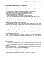
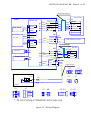
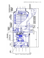
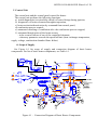
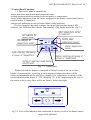
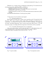
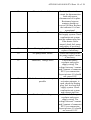
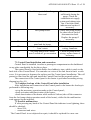
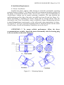
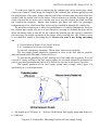
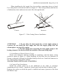
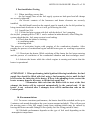
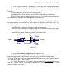
MANUFACTURER:
LLC Advers
11 Lesnaya Street,
Samara, 443100 Russia
Tel. (846) 270-68-64
Fax (846) 270-65-09
E-mail: [email protected]
Air Heaters
- PLANAR – 4D –12
Operation Manual
ADVR.010.00.00.000 RE
ADVR.010.00.00.000 RE. Sheet 2 of 26
TABLE OF CONTENTS
1
2
3
4
5
6
7
8
9
10
11
12
13
14
15
16
17
Introduction
Basic Parameters & Specifications
Safety Measures
Description of Heater Operation and Structure
Heater Control Unit
Scope of Supply
Control Unit Functions
Installation Requirements
Post-Assembly Testing
Recommendations
Possible malfunctions during operation and Remedial Procedure
Transportation and Storage
Warranty
Packing Certificate
Acceptance Certificate
Vending & Assembly Certificate
Warranty Certificates
Sheet
3
3
4
5
8
8
10
16
21
21
23
23
23
24
24
25
26
ADVR.010.00.00.000 RE. Sheet 3 of 26
1 Introduction
This Operation Manual is intended to familiarize the User with salient features,
operation, assembly and operating procedures for PLANAR–4D-12 (hereinafter
called “the heater”) intended for heating a vehicle driver workplace and various
compartments of a motorized vehicle at atmospheric temperatures as low as -45°С (113 F).
The complete operative scope of the heater comprises the following functions:
- provision of controllable air heating for an inhabited enclosed area in accordance
with the atmospheric air temperature,
- provision of forced air ventilation for an inhabited enclosed area.
Minor changes performed on the heater structure by the Manufacturer may not be
documented in this Operation Manual.
When placing an order or referring to the heater in documents pertaining to other
types of equipment, the heater codes will read as follows:
Diesel Air Heater PLANAR–4D-12 TU4591-008-40991176-2005,
2 Basic Parameters & Specifications
The basic heater specifications are quoted in Table 1.
The basic parameters are quoted to a margin of ±10% tolerance at a temperature of
20°С at a nominal voltage.
Table 1
Parameter Code
Nominal Supply Voltage, V
Fuel Type
Heating Efficiency:
max, kw,
min, kw,
Heated Air Volume:
Max , m3 /hr
Min, m3 /hr
Fuel Consumption at:
Max power, l/hr
Min power, l/hr
Start/Stop Mode
Maximum Weight, kg
Heater power consumption,W
Doesn’t exceed while heating
mode
Max,W
Min,W
Version
PLANAR–4D–12
12
Diesel Oil in compliance with GOST 305,
atmospheric temperature-dependent
3
1
120
70
0.37
0.12
Manual
8
45
10
ADVR.010.00.00.000 RE. Sheet 4 of 26
3 Safety Measures
3.1 The installation of the heater and its fittings shall be performed by authorized
organizations only.
3.2 The heater may only be used for the purposes specified herein.
3.3 The fuel supply line shall not be installed inside the passenger compartment or
cabin of a motor vehicle.
3.4 A vehicle that uses the heater shall be equipped with a fire extinguisher.
3.5 The environment where the heater is to be used shall be free of highly
inflammable vapours and a large quantity of dust.
3.6 To prevent the possibility of exhaust gas poisoning, the heater shall not be
used when the vehicle is in an enclosed area (garage, workshop, etc).
3.7 When refueling the vehicle, the heater shall be switched off.
3.8 When performing welding operations on the vehicle or repairs on the heater,
disconnect the heater from the vehicle battery.
3.9 When assembling or dismantling the heater, observe the safety measures
specified by electric work regulations for the fuel supply system and the vehicle’s
wiring system.
3.10 The heater shall not be connected to the vehicle electric circuit while the
engine is running or the battery is switched off.
3.11 The heater’s electric power supply must not be disconnected before the
end of the purge cycle.
3.12 The heater’s connectors must not be connected or disconnected while the
heater’s electric power supply is turned on.
3.13 Wait 5 to 10 seconds before switching the heater back on.
3.14 In the event of two subsequent ignition failures, contact the maintenance
department to report a malfunction.
3.15 In the event of a failure in heater operation, contact a designated repair
organization authorized by the Manufacturer.
3.16 Manufacturer warranty shall not apply if the above requirements are not
adequately met.
ADVR.010.00.00.000 RE. Sheet 5 of 26
4 Description of Heater Structure and Operation
The heater operates independently from the vehicle engine.
The fuel and electric power supply is provided by the vehicle. See Figure 4.1 for
the heater wiring diagram.
The heater is a self-contained heating device comprising the following:
- Heating device (See Figure 4.2 for basic components thereof);
- Fuel supply pump providing fuel for the combustion chamber;
- Ignition and indicator device (control unit);
- Wiring harness connecting heater fittings to the vehicle battery.
The heater’s operating principle is based on heating air driven through the vehicle’s
heat exchange system.
The heat source are fuel combustion gases from the combustion chamber. The
resulting heat warms the walls of the heat exchanger, which is air-blown from the
outside. Air passes through the ribbing of the heat exchanger and enters the passenger
compartment or other compartments of the vehicle.
Upon ignition, check the heater to ascertain whether fittings such as the flame
indicator, the overheat sensor, air pump motor, plugs, fuel supply pump and the electric
circuits thereof are working properly.
If no problem is detected, the ignition process starts.
In accordance with the preset sequence, the combustion chamber is fore-purged
and the heating plug warms up to the required temperature. Air and fuel starts to enter
the combustion chamber under the same procedure, whereupon the ignition process is
initiated. Once stable combustion is achieved, the heating plug switches off. Flame
control is provided by the flame indicator. All processes involved in heater operation
are monitored by the control unit.
The control unit controls heat exchanger temperature and halts the combustion
process as soon as the temperature exceeds the specified limit. The heater may be
switched off at any time.
Pressing the heater deactivation command stops the fuel entering and the
combustion chamber is purged with air.
During automated operation control of the heater in emergency situations, bear in
mind the following:
1) In the event of ignition failure, the process will be repeated. The heater will
switch off following two consecutive ignition failures,
2) If a combustion failure occurs while the heater is in operation, the heater will
switch off,
3) If the heat exchanger is overheated (maybe as a result of closure of the heater
inlet/outlet vents), the heater will switch off automatically,
4) If voltage drops below 10.5 V or exceeds 16 V the heater will switch off.
5) In the event of emergency shutdown, the indicator will show the information
according to the code of malfunction.(see table 7.1)
Flashing frequency corresponds to failure type, see Section 12 for details.
ADVR.010.00.00.000 RE. Sheet 6 of 26
Control Panel harness
XS1
Heater
Flame indicator
Control unit
black*
red*
Circuit
1 Chromel
2 Alumel
Circuit
1 +12V
black*
2 General
brown Circuit
yellow +12V
white General
green output data
input data
green*
Air pump
XÐ4 XS4
brown
yellow 1
white 2
green 3
4
5
1
2
3
4
XS2 XP2
Circuit
black
General 1
Sensor 2 red
black
red
Circuit
1 PWM
black*
2 Revolutions
Control Panel
XÐ1
yellow*
Circuit
+ 12V
General
Output data
input data
Cabin temperature sensor
Fuel pump harness
XS3 XP3
Circuit
red 1
Control 1
2
General 2 blue
Glow plug
red
blue
Bi-metall termo breaker
fuel pump
XS5 XP5
Circuit
red
1 Control
blue 2
General
XP13 XS13
Circuit
red-white
+12V
black
- 12V
1
2
red-white
black
Supply harness
XÐ5
1
Battery
+12V
-
2
2
XÐ4
25À
XS5
1
XS4
1
1
5
5
25À
Vehicle
XP1
3 4
3 4
2
1
1
2 2
2
2
XÐ3, ÕÐ13
XP2
1
1
XS2
1
* - the colorof marking on flameindicator and air pump wiring .
figure 4.1- Wiring Diagram
ÕS3, ÕS13
2 1
XS1
ADVR.010.00.00.000 RE. Sheet 7 of 26
Figure 4.2 – Basic Heater Components
ADVR.010.00.00.000 RE. Sheet 8 of 26
5 Control Unit
The control unit and the control panel control the heater.
The control unit performs the following functions:
а) initial diagnostics (serviceability check) of heater fittings during ignition,
b) diagnostics of heater elements throughout operation,
c) heater activation/deactivation by command from control panel;
d) combustion process control;
e) automated switching of ventilation after the combustion process stopped;
f) automated deactivation of the heater occurs:
- in the event of failure of one of the controlled elements,
- when any parameter exceeds the specified limit (heat exchanger temperature,
supply voltage, combustion chamber flame failure)
6. Scope of Supply
See Figure 6.1 for scope of supply and connection diagram of basic heater
components. For list of basic heater components, see Table 6.1.
2
5
1
ÕP2
ÕS1
+
53
ÕP13
-
12
11
27 (4øò.)
50 (8øò.)
ÕS3
30
38
43
19
Fuel
4
20
21
51
30
38
43
18
30
38
9
22
36
6
18
25
8
Surface of cabin
(vehicle)
52
13
10±1
36
17
30
38
36
49
17
30
38
Figure 6.1 – Connection Diagram of Basic Heater Components
38 (4øò.)
41 (4øò.)
43 (4øò.)
30
38
43
ADVR.010.00.00.000 РЭ. Sheet 9 of 26
Table 6.1
No.
1
2
4**
5
6
8
9
11
12
13*
17
18
19
20**
21**
22
25
27
30
36
38
41
43
49*
50
51**
52
53
Designation
Heater
Control panel ПУ-8 with harness
Fuel Supply Pump, Holder, Clamp (Set), Gasket(set)
Cab temperature sensor
Fuel Supply Pump Harness
Fuel supply intake
Heat insulation
Air Intake
Power Supply Harness
Screen
Holder
Exhaust Pipe Clamp
Air Inlet Clamp
Shock absorber
Holder
Exhaust Pipe
Connecting Tube (polyamide) L = 5500 mm
Socket (L= at least 50 mm)
Bolt М6х16
Screwm6.4*16
Nut М6
Enlarged Flat Washer ∅6
Split Washer ∅6
Clamp Torro 20*32/9W1
Clamp АВА min 10\9
Clamp Torro 35*50/c7W1
Clamp 13*26
Plastic Clamp
Pieces Per
Set
1
1
1
1
1
1
1
1
1
1
2
3
1
1
1
1
1
4
7
4
11
4
8
1
8
1
1
15
ADVR.010.00.00.000 РЭ. Sheet 10 of 26
7 Control Panel Functions
7.1 The control panel is intended for:
-heater activation and deactivation in manual mode;
-setting operation mode according to desired power or temperature;
-heater status indication (from the sensor integrated in the heater, control panel unit or
external sensor if connected;
-failure code indication in case of heater failure while operation.
The front board of the panel contains: four-digit light emitting doide (LED)
indicator, two LEDs and three knobs. Functionality of the knobs and LEDs. (fig.7.1)
LED indicator N2
(power mode)
LED indicator N1
(temperature mode)
Cabin temperature sensor
(if connected)
Control panel
temperature sensor
12
Heater temperature
sensor
mode selecting/decreasing
of power or temperature
Sensor selecting/increasing of
power or temperature
Setting of operation mode/heater
ON-OFF knob
Fig. 7.1- Control panel
While first time the heater is connected to electric circuit of the car or after
breaks of power supply, according to environmental temperature there will be
following information on the panel (for example)- the temperature in the area of the
sensor installed in the heater is -12°C (drawing 7,2), if the temperature in the area of
the sensor is above zero, there will be no “mines” before the figure.
12
fig 7.2- View of the indicator after connection to electric circuit of the heater (initial
stage of the indicator)
ADVR.010.00.00.000 РЭ. Sheet 11 of 26
With the view to energy saving , the indicator stops glowing 20 seconds after last
pressing of any knob, while this LED#1 or LED#2 is :
- lightning constantly if the heater is activated;
- blinking rarely (1 time per 1,5 second) if the heater is not activated;
- blinking while fault (1 time per second);
- blinking frequently (5 times per second) while deactivation of the heater (while
purging)
To restart the indication there’s need to press any knob.
7.2 Succession of work with the control panel
7.2.1 Operation mode set up.
Before heater activation there’s need to select operation mode. Pressing knob with
the arrow “A” select operation mode of the heater according to desired power or
temperature. According to the choice the LED#1 orLED#2 is lightning. After selecting
the mode “according temperature” there’s need to press knob with the arrow “B” and
choose the sensor, according which the temperature of the heater will be controlled.
7.2.2 Activation and setting the power or temperature.
After mode selection there’s need to press the knob “O”, while this the heater will
start working and there’s information on the indicator- the power mode or
temperature mode according to your choice.(see fig. 7.3 or 7.4)
18
Fig. 7.3 (power mode)
Fig. 7.4 (temperature mode)
ADVR.010.00.00.000 РЭ. Sheet 12 of 26
If
power mode is selected, pressing knobs with arrows “A” (decreasing),
“B”(increasing) – you can set up the necessary power (see fig. 7.3)which can be set
within 1 to 3 kWt. The indicator shows the scale according which the power is set up.
If temperature mode is selected , pressing knobs with arrows “A” (decreasing),
“B”(increasing) – you can set up the necessary temperature (see fig. 7.4). The
temperature is set within 15° to 30°C. You can see the figures on the indicator.
Attention!
1. The heater Operation mode (according to power or temperature) is saved
until new set up.
2. If cabin temperature sensor circuits are disconnected heater will go
working on middle power Operation mode.
3.While heater activation without setting operation modes it is necessary to
press the knob “O” one time if the indicator is lightning, and 2 times if the
indicator is not lightning.
7.2.3 Heater deactivation.
To deactivate the heater press the knob “O”. While this the heater is in switching
off mode, that means that the combustion process in combustion chamber is stopped
and the process of purging is started. According to the mode the indicator will show
information(for example) (see pictures 7.5 or 7.6), the LED#1 or LED#2 will be
blinking frequently until the process of purging is stopped.
25
Picture 4.5-Purge
Picture 7.6- Purge
Attention!
It is forbidden to switch off electric power supply before purge cycle is
finished.
ADVR.010.00.00.000 РЭ. Sheet 13 of 26
7.2.4 Indication of malfunction code while failures in heater operation
While heater activation and operation there can be malfunctions. In case of
malfunction the control unit automatically deactivate the heater. Every malfunction is
coded and automatically appears on the indicator(see fig 7.7). While this, malfunction
‘s code and the LED showing the operation mode of the heater will blink rarely. The
heater’s malfunction codes are described in table 7.1. Pressing of any knob of the
control panel will switch off indication of the malfunction code and bring the control
panel in initial state.
02
fig 7.7
Table 7.1-Malfunction codes
Malfunction code
01
02
04
Problem description
Commentary
Problem solution
Heat Exchanger overheating
Check the inlet/outlet pipe
of the heater for
unpumped heated air
flow. Check the overheat
sensor on the heat
exchanger, replace if
necessary.
Possible overheating on
While purging before start
temperature sensor. The sensor
the control unit is not
temperature (control unit) is more cooled enough or control
than 55°C
unit is overheated during
operation. Check
inlet/outlet pipe of the
heater for unpumped
heated air flow and repeat
activation to cool the
heater.
Built-in temperature sensor on
Replace the control unit
control unit failure
ADVR.010.00.00.000 РЭ. Sheet 14 of 26
05
Flame indicator failure
08
Flame failure
09
Heating plug failure
10
Air pump motor failure
12
Shutdown, voltage boost
13
No further activation attempt is
possible
15
Shutdown, low voltage
Check the flame indicator
circuit for disconnection
fault with sensor
disconnected of its plate.
Resistance between
contacts should not
exceed 10 Ohm. Replace
the indicator if it is not
operational.
Check the fuel level and
fuel supply system. Check
combustion air system
and the exhaust pipe line.
If the heater can be
started, check fuel pump
and replace if necessary.
Check the plug and
replace if necessary.
Check the wiring of the
air pump, replace motor
if necessary.
Check the battery,
regulator and power
supply wiring. The
voltage between 1 contact
and 2 contact of connector
XP13 (see connection
layout picture 4.1) should
not exceed 16V
If possible quantity of
activation attempts is
used, check the heating
plug, fuel level and fuel
supply system. Check
combustion air system
and exhaust pipe line.
Check the battery,
regulator and power
supply wiring. The
voltage between 1 contact
and 2 contact of connector
XP13 (see connection
layout picture 4.1) should
not exceed 10.5V
ADVR.010.00.00.000 РЭ. Sheet 15 of 26
16
Ventilation period takes longer
than usual
17
Fuel pump failure
20
No connection between Control
panel and the heater
Air pump motor fault. Motor
won’t rotate
Air pump motor fault. Motor
won’t switch off, go on rotation
27
28
The heater is not cooled
sufficiently during the
purge. Check the
combustion air supply
system and exhaust pipe
line. Check the flame
indicator and replace if
necessary.
Check fuel pump wiring
for short-circuit fault or
disconnection fault.
Replace the pump if
necessary.
Check wiring, connectors.
Check air pump motor
wiring, connector.
Check air pump motor
wiring, replace motor if
necessary.
7.3 Control Panel installation and connection
Control Panel is installed in cabin or passengers compartment on the dashboard
or any other comfortable for the driver place.
The control Panel is fixed with double-faced adhesive tape, which is stuck to the
back side of the Control Panel. You can take out wires of the unit from its back or side
cover. It is necessary to degrease the surface used for Control panel installation. Take off
protective film from the tape and install the Control Panel on the prepared surface.
The connection of the Control panel to the heater is performed according wiring
diagram(see fig. 4.1)
7.4 Complex checkup of the Control Panel after installation
After installation and connection of the Control panel to the heater the checkup is
performed in following way:
-set up the necessary operation mode on the Control panel;
-check activation and deactivation of the heater;
-check deactivation of the heater while artificial failure (take off the connector
from the fuel pump during operation mode of the heater), while this the malfunction
code appears on the indicator.
7.5 Possible malfunctions
If after pressing any knob of the Control Panel the indicator is not lightning, there
should be checked:
- fuses-25A;
- connectors and wires.
The Control Panel is not subjected to repair, it should be replaced for a new one.
ADVR.010.00.00.000 RE. Sheet 16 of 26
8 Installation Requirements
8.1 Heater Installation
Installed the heater indoors while bearing in mind the permissible operating
positions shown in Figure 5. The figure shows the two maximum assembly positions of
the heater. Positioned the heater’s inlet vent in such a way to prevent absorption of
vehicle/heater exhaust gas in normal operating conditions. The gap between the
walls/partitions and the edge of the inlet vent shall be at least 50 mm (see Figure 8.1).
When assembling or operating the heater, ensure that no foreign objects enter the
inlet/outlet vents. Prior to assembly, ensure availability of spare heating plug and bear
in mind dismantlement requirements, as this will permit easier maintenance in future.
See Figure 8.2 for how to position mounting holes to install the heater into the motor
vehicle casing. Overall and mounting Dimensions are on the fig.8.3
ATTENTION !! To ensure reliable performance, follow the above
recommendations carefully. Install the heater horizontally with the heating plug
in the up position as shown in Figure 8.1.
Figure 8.1 – Mounting Options
ADVR.010.00.00.000 RE. Sheet 17 of 26
Ç11
18
12
Ô 21
44
Ô6,5
4 îòâ.
Ô 25
55
Figure 8.2– Mounting Holes Used for Heater Installation
Ç157
ÕS1
ÕP13
40
18
8
M6
4 øïèëüêè
Ç90
44
84,5
55
14
103
Ç147,5
Ç138
Ç82
4 5Å
12
ÕS3
R26
17
82
158
392
24
160
Figure 8.3- Heater dimensions
8.2 Air Inlet Installation
Do not allow combustion air to be sucked in from the passenger compartment or
vehicle cabin or boot. Position the pipe’s air inlet vent to prevent snow entering or
choking the pipe and to allow incoming water to run off. Ensure the vent is not facing
oncoming air.
8.3 Exhaust Pipe Installation
When installing the exhaust pipe, be mindful of its high operating temperature. Cut
the exhaust pipe (a flexible corrugated metal hose) to size. Fix the exhaust pipe in
place using clamps and position it at a slight angle following the trajectory of gas flow.
To protect some parts of the vehicle (electric wiring and other harness) from high
temperatures, there must be heat insulation installed.( pos.9, fig.6.1)
ADVR.010.00.00.000 RE. Sheet 18 of 26
To achieve a tight fit, prior to connecting the exhaust pipe to the heater pipe, make
a saw-cut of about 15mm along the length of the exhaust pipe without going beyond
the gripped part of the pipe. Ensure that the end of the exhaust pipe does not come into
contact with the rubber seal of the heater. Direct exhaust gas outside. Position the gas
outlet vent and the air inlet vent in such a way as to prevent exhaust gas from entering
the combustion chamber. Ensure that exhaust gas does not enter the passenger
compartment of the vehicle and that it does not get sucked in through the vehicle fan.
Do not allow exhaust gas to affect the performance of vehicle components. Position
the exhaust pipe outlet vent so as to prevent snow entering or choking the pipe and to
allow incoming water to run off. At the vent of the exhaust pipe the screen is installed,
this necessary for stable operation of the heater while working low idle. If thee screen
is not installed, install it according fig.6.1 Ensure the vent is not facing oncoming
air.
8.4 Installation of Heater Fuel Supply System
8.4.1 installation of Heater fuel pump
To prevent emergency situations, follow these instructions carefully.
The fuel supply pump should be mounted as close to the fuel tank as possible
and positioned below the tank’s lower fuel level.
To prevent the possibility of fuel leaking out of the tank (due to gravity flow) as
a result of faulty sealing of the fuel supply pump, the fuel tank should be positioned in
such a way that the maximum fuel level is below the incision in the heater fuel tube.
The spatial position of the fuel supply pump must comply with Figure 8.4
(preferably in a vertical position).
а – lift height up to 700 mm; b – delivery lift between fuel supply pump and heater up
to 1500 mm.
Figure 8.4- Permissible Mounting Position of Fuel Supply Pump
ADVR.010.00.00.000 RE. Sheet 19 of 26
8.4.2 Fuel intake through fuel supply intake.
Fuel can enter the heater through a fuel supply intake from the fuel tank according to
fig.8.5. a) Perform installation of special washer with fuel supply intake to the tank
inlet according to fig.8.5,b) Perform installation of the fuel supply line from fuel
supply intake to the heater according to fig.8.6.
à)
1
á)
2
3
6
Ç 16
Êîðïóñ òîïë. áàêà
Ç 16
5
5
4
1
1 - fuel supply intake
2- nut 8
3- washer 8
4-washer 8
5- special washer
6-gasket
Fig 8.5 – Fuel supply intake installation
Íàãðåâàòåëü
íå
å
ëå
áî
0
50
ìì
x
ma
6
5
00
20
max
4 0 00 ìì
5
x
ma
2
ìì
1
45
5-7 ìì
5
1 - liquid phase heater fuel tank
3
3
4
4 - fuel pump
2 - fuel supply intake of liquid phase 5 - sleeve
heater
3 – fuel supply line d=2mm
6 – fuel supply line d=5mm
Figure 8.6 – Installation Diagram for Heater Fuel Supply System Using a fuel supply
intake
ADVR.010.00.00.000 RE. Sheet 20 of 26
When installing the fuel supply line, do not allow connecting sleeves to bend.
Use a sharp knife to cut the fuel tube as in Figure 8.7. The cutting location shall be free
of indentations, hairs and must not restrict flow through the tube.
Correct
Правильно
Incorrect
Неправильно
Figure 8.7 – Tube Cutting Prior to Installation
ATTENTION
1. Do not allow the fuel supply line or fuel supply pump to
overheat. Do not install the fuel supply line and fuel supply pump near the
exhaust pipe or on top of the engine.
2 The fuel supply line connecting the fuel supply pump to the
heating element of the heater should be installed at the same lifting angle.
8.5 Installation of Heater Electric Circuit
Heater wire harnesses shall be installed in compliance with the heater wiring
system as shown in Figure 4.1. When installing, do not allow the wire harnesses to
become overheated, deformed or dislodged during vehicle use. Attach the harnesses to
the vehicle fittings using plastic clamps.
Attention! Remove the fuse prior to installation.
8.6 Control Panel Installation
Install the control panel on to the dashboard in the cabin or passenger
compartment of the vehicle. Attach the Control panel with the help of adhesive tape.
Degrease the surface on which the panel is installed and remove protective film from
the adhesive tape.
ADVR.010.00.00.000 RE. Sheet 21 of 26
9 Post-installation Testing
9.1 When installing, ensure that:
- the fuel supply lines of the fuel supply system are leak-proof and all clamps
are securely tightened,
the electric contacts of the harnesses and heater elements are securely
installed,
- the shift knob located on the control panel is turned to the far left position by
being turned anti-clockwise as far as it will go following the click.
9.2 Install fuse 25А .
9.3. Fill the fuel pipe system with fuel with the help of fuel pumping
device(fuel pumping device УПТ-1 can be ordered at manufacturer).After filling the
system check that the fuel pump system is not leaking.
9.4 Check that the heater is working :
- in ventilating mode,
- in heating mode.
The process of activation begins with purging of the combustion chamber. After
purging the process of combustion begins and the heater goes on working in operation
mode.
9.5. Deactivate the heater. While switching off the heater the fuel stops entering
and the process of ventilation of the combustion chamber and heat exchanger starts.
9.6 Activate the heater while the vehicle engine is running and ensure that the
heater is operational.
ATTENTION! 1 When performing initial ignition following installation, the fuel
supply line should be filled with fuel using a fuel pumping device until the fuel
level reaches the inlet plug of the heater. If there is no pumping device, restart the
heater as many times as necessary to fill the fuel supply line.
2 Remember that each time the heater fails to start at the first
attempt, the heater will be restarted automatically by the control unit. If the
heater is not activated after 2 attempts, there will be malfunction code on the
Control panel.
10. Recommendations
10.1 To ensure consistent performance, the heater should be switched on for up to
5 minutes each month throughout the year (warm seasons included). This will prevent
the moving parts of the fuel supply pump from sticking,(which may be caused by
leaving the heater movable fittings in low-quality fuel for a long period of time).
10.2 Reliable performance depends on the type of fuel used depending on the
atmospheric temperature.
ADVR.010.00.00.000 RE. Sheet 22 of 26
10.3 An untimely switch to a winter type of fuel may cause a paraffin blockage
in the fuel inlet tube filter (if applicable) located in the fuel tank and in the fuel supply
pump filter, which may prevent the heater from starting or cause it to stall in midoperation.
To fix breakdowns, proceed to the following steps:
a) change the fuel in the fuel tank as according to the ambient temperature,
b) If the heater does not operate properly once the fuel was changed according to
the temperature , check the fuel supply pump filter as follows:
- remove the fuel supply pump from the vehicle; using a wrench (F/A 17), fix
the pump in place, unscrew the pipe stub and remove the filter (see Figure 10.1). Do
not fix the pump in place using surfaces other than Surface A when removing and
installing the pipe stub,
- rinse the filter in gasoline and blast it with compressed air,
- install the filter into the fuel supply pump; use sealant when installing the pipe
stub,
- install the fuel supply pump and check if the heater works.
Ball
Øàðèê
À
Ôèëüòð
Filter
Âõîä
Âûõîä
Outlet
Inlet
Ïðóæèíà
Øòóöåð
17
Spring
Pipe
Stub
Figure10.1
10.4 Check the battery charge level on a regular basis.
10.5 While operation Control unit program failure is possible. For example, the
heater is not activated or deactivated, does not come to sufficient heating power.
To fix the failure it is necessary to disconnect the blocks on the power supply harness
XP13 and XS13(fig.4.1) for 1-2 min.
10.6 While long storage of the vehicle it is recommended to switch off the heater
from the vehicle battery to avoid its discharging (current consumption in non
operation mode 30-40 mA)
DVR.010.00.00.000 RE. Sheet 23 of 26
11. Remedial Procedure for Heater Ignition Problems
11.1 Certain problems may be solved without contacting a maintenance station.
If the heater does not operate when switched on, proceed to the following steps:
1) Check the fuel level in the tank and in the fuel supply line beyond the fuel
supply pump,
2) Check fuse 25А,
3) Check to see that all the contacts of the connectors and the fuse block are
securely joined (contact corrosion is possible),
4) disconnect blocks XP13 and XS13 of the power supply harness connector (fig
4.1) for 1-2 min and then connect them.
11.2 All other types of heater malfunction will be indicated automatically on the
control panel according to the malfunction code.
11.3 If there are malfunctions except those specified in 11.1 does not remedy
any of the problems that you may be having, please contact an authorized maintenance
station.
12 Transportation & Storage
12.1 The heaters are safe to transport and may be transported by any means of
transport, including air and rail transport providing the packed products are protected
from atmospheric precipitations and climatic factors as per requirements specified in
Section 5 of GOST 15150-69 and mechanical effects as per requirements specified in
Category S of GOST 23216-78.
12.2 As far as climatic factors are concerned, transportation and storage conditions
shall comply with storage requirements set out in Section 5 of GOST 15150-69.
13 Warranty
13.1 The heaters carry a warranty period of 18 months from the date of sale and
have a warranty lifetime of 1,000 hours or 45,000 km in terms of vehicle mileage,
provided that the Consumer observes the rules of use, transportation and storage
specified herein.
13.2 If there is no organization stamp specifying the date of sale, the warranty
period begins from the date of the heater’s manufacture.
13.3 During the warranty period, all defects occurring through the Manufacturer’s
fault will be repaired by the personnel of authorized car-care centers, using the
necessary spare parts provided free of charge by the Manufacturer.
13.4 The Manufacturer does not accept any liability for incomplete delivery or any
mechanical damage occurring after sale.
13.5 The following defects and damages are excluded from warranty coverage:
- all defects and damages caused by force-majeure such as lightning strike, fire, flood,
excessive voltage fluctuations, car accident, etc.,
- all defects and damages caused by violation of rules of installation, use, storage and
transportation specified herein,
ADVR.010.00.00.000 RE. Sheet 24 of 26
- all defects and damages caused by installation, repairs or commissioning of the heater
performed by persons or organizations unauthorized by the Manufacturer to perform
the said operations,
- improper use of the heater.
14 Packing Certificate
The PLANAR – 4D-12 heater
serial No. ___________________________________________________
has been packed by the Manufacturer LLC Advers in compliance with the
requirements set out in the applicable specifications.
Date of Packing______________________________________
Performed by________________________________
Signature
Accepted by ________________________________
Signature
Stamp here
Technical Inspection Department
15 Acceptance Certificate
The PLANAR – 4D-12 heater
serial No. ……………………………….……………………….,
Program Code……………………………, has been manufactured and accepted in
compliance with Specification TU 4591-008-40991176-2005 and applicable
specifications and declared ready to use.
Manufacture Date
Stamp here
Technical
Inspection
………………………..……………………
………………………………………………………
(SPA’s Signature)
ADVR.010.00.00.000 RE. Sheet 25 of 26
16 Vending and Assembly Certificate
16.1 The PLANAR – 4D-12 heater
serial No. …………………………………..……….
Point and Date of Sale…………………………………………..
Stamp
here
………………………………………….
(Vendor’s Signature)
By signing below I confirm that I have read, understood and agreed to all of the
above terms & conditions of this warranty, and have read and understood the provided
Operation Manual, and that the product does not have any cosmetic damage, and that
all components within the scope of supply are in place:
………………………………………..
(Purchaser’s Signature)
16.2 The heater has been installed and tested:
on Motor Vehicle (make / model / license no.) - ………………………………….
owner - ……………………………………………………………………..
organization - ……………………………………………………..
Stamp
here
…………………………………………………….
(SPA’s Signature)
ADVR.010.00.00.000 RE. Sheet 26 of 26
Limited Liability Company
Advers
11 Lesnaya Street, Samara, 443100 Russia
Tel. (846) 270-65-09, Fax (846) 270-68-65
….…..……………
(Initials and Signature)
Serial No……………
Date and Point of Sale
Stamp here
Manufacture Date………………..
…………………………………………………………………
…………………………………………………………………
…………………………………………………………………
(SPA’s Signature)
Date and Point of Assembly
.……………………………………………………………….
…….………………………………………………………….
………………………………………………………………..
Stamp Here
(SPA’s Signature)
Performed by
The following operations have been performed to repair the following defect:
……………………………….
…………………………………………………….. ……………………………………..
…………………………………………………………………………………………….
Performed by ……………………………………………….…….
on ……………….
(Date)
Counterfoil to Warranty Certificate No 2
Warranty Repairs for PALNAR– 4D-12
Certificate No 2
Warranty Repairs for PALNAR– 4D-12
(Initials and Signature)
Stamp here
Manager
. ……………………………………………
(the name of the Repairer)
……….…………………………………………….
(SPA’s Signature)
Owner ……………….
(Signature)
Certificate No 1
….…..……………
(Initials and Signature)
Warranty Repairs for PALNAR– 4D-12
Serial No……………
Manufacture Date………………..
Performed by
Warranty Repairs for PALNAR– 4D-12
Date and Point of Sale
Stamp here
…………………………………………………………………
…………………………………………………………………
…………………………………………………………………
(SPA’s Signature)
Date and Point of Assembly
.……………………………………………………………….
…….………………………………………………………….
………………………………………………………………..
Stamp here
(SPA’s Signature)
The following operations have been performed to repair the following defect:
……………………………….
…………………………………………………….. ……………………………………..
…………………………………………………………………………………………….
Performed by
……………………………………………….…….
on ……………….
(Date)
Counterfoil to Warranty Certificate No 1
на
Stamp
here
(Initials and Signature)
Manager
. ……………………………………………
(the name of the Repairer)
……….…………………………………………….
(SPA’s Signature)
Owner ……………….
(Signature)