1
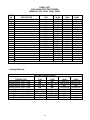
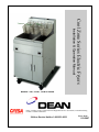
Cool Zone Series Electric Fryers
Installation & Operation Manual
Models 714E, 1414E, 1818E & 2020E
Dean, a member of the Commercial Food Equipment Service Association, recommends using
CFESA Certified Technicians.
24-Hour Service Hotline 1-800-551-8633
Price: $6.00
819-5867
PLEASE READ ALL SECTIONS OF THIS MANUAL AND RETAIN FOR FUTURE
REFERENCE.
This product has been certified as commercial cooking equipment and must be
installed by professional personnel as specified.
We suggest installation, maintenance and repairs should be performed by your
local Factory Authorized Service Center.
INSTRUCTIONS TO BE FOLLOWED IN CASE THE USER SMELLS GAS ARE TO BE POSTED
IN A PROMINENT LOCATION. THIS INFORMATION SHALL BE OBTAINED BY CONTACTING
THE LOCAL GAS COMPANY OR GAS SUPPLIER.
FOR YOUR SAFETY, DO NOT STORE OR USE GASOLINE OR
OTHER FLAMMABLE VAPORS AND LIQUIDS IN THE VICINITY
OF THIS OR ANY OTHER GAS APPLIANCE.
IMPORTANT
SAFE AND SATISFACTORY OPERATION OF YOUR EQUIPMENT DEPENDS
ON IT’S PROPER INSTALLATION. INSTALLATION MUST BE
PLANNED IN ACCORDANCE WITH ALL APPLICABLE STATE
AND LOCAL CODES.
WARNING
Safety labels are a required component of this unit. If missing, or not legible, they must be
replaced. Inspect periodically and replace if necessary. Replacement labels are available
free of charge from the factory.
TABLE OF CONTENTS
1. DESCRIPTION AND SPECIFICATIONS.....................................................1
2. PRE-INSTALLATION......................................................................................2
3. RECEIVING AND INSTALLING THE FRYER ............................................2
4. INITIAL START-UP.........................................................................................3
5. DAILY OPERATION ........................................................................................4
6. CLEANING & MAINTENANCE.....................................................................5
7. TROUBLESHOOTING.....................................................................................6
8. RECOMMENDED SPARE PARTS/PARTS LIST .........................................7
9. FACTORY SERVICE & PARTS ORDERING..............................................11
10. SPECIFICATIONS......................................................................................12
11. WIRING DIAGRAMS..................................................................................13
LIMITED WARRANTY.......................................................................................17
front door on or near the cabinet floor. Optional
panel-mounted main power switch, rocker-type
reset switch, melt cycle switch, and instant
power switch are mounted on control panel.
1. DESCRIPTION AND
SPECIFICATIONS
The Dean Industries Electric Deep Fat Fryers
are energy-efficient, electrically heated units,
listed by the Underwriter's Laboratory, and
manufactured to the following basic
performance and application specifications. All
units are shipped complete assembled, with any
accessories packed inside the fryer tank. All
units are adjusted, tested and inspected at the
factory prior to crating for shipment.
MODEL
FRYING VESSEL
Frying Area:
Oil Capacity
ELECTRICAL
REQUIREMENTS:
Wattage:
Amperage:
714E
1414E
1818E
6-3/4x14
25#
14x 14" 18x18"
40#
70#
Melt Cycle:
This feature pulses the heating elements on and
off at a controlled rate. This should be used
when the fryer is being used with solid
shortening.
Instant power:
Except on bulb and capillary type thermostats,
this feature by-passes the temperature
controller for a pre-set period of time to provide
maximum heating power into frying compound
and to allow the operator to anticipate heavy
use.
2020E
20x20
80#
AUTOMATIC SAFETY FEATURES:
a) High temperature detection to shut off
power to the heating elements should the
controlling thermostat fail.
18KW
208V, 3hp, 49.9
ALL
MODELS
208V, 1hp, 86.5
240V, 3hp, 45.7
240V, 1hp, 75.0
APPROX. SHIPPING
115#
153# 190#
200#
Note: 1818E and 2020E are also available in 13.5 KW
models.
b) Optional safety switch built into the drain
valve prohibits element operation with the
drain valve even partially open.
RATING PLATE:
This is riveted to the inside right-hand corner of
the fryer door.
VESSEL CONSTRUCTION:
Welded, heavy gauge stainless steel; three
heater elements fixed inside the vessel with an
inner chromed wire mesh protective crumb
screen over the elements. Drain tapped into
center of vessel with front-controlled manual
ball valve.
Information on this plate includes the model and
serial numbers; when communicating with the
factory about a unit or requesting special parts
or information, this data is essential for proper
identification. Other information on this plate is
the kW output of the heaters and electrical
requirements.
BODY CONSTRUCTION:
ALL DEAN INDUSTRIES DEEP FAT
FRYERS MUST BE CONNECTED ONLY TO
THE TYPE OF ELECTRICAL SERVICE
IDENTIFIED ON THIS RATING PLATE!
Welded steel base, with visible surfaces of
brushed Series 300 stainless steel or painted
steel. Frame supported by 6" adjustable legs or
5" casters on line-ups of multiple units.
OPERATING CONTROLS:
Unit is shipped standard with a liquid bulb filled
thermostat or an optional solid state
temperature controller. Either temperature
control is mounted in the cabinet behind the
1
2. PRE-INSTALLATION
3. RECEIVING &
INSTALLING THE FRYER
GENERAL:
Installation of any heavy-duty electrical
appliance should be made by a licensed
electrician.
UNPACKING:
Check that the container is upright. Use
outward prying - no hammering - to remove the
carton. Check the fryer(s) for visible damage; if
such damage has occurred, do not refuse
shipment, but contact the carrier and file the
appropriate freight claims. Do not contact the
factory, as the responsibility for shipping
damage is between the shipper and the dealer
or end-user.
STANDARDS:
Installation must be planned in accordance with
all applicable state and local codes, taking into
account the following standards:
a) Nat'l Electrical Code ANSI/NFPA
#70-1984:
American National Standards Institute
1430 Broadway
New York, NY 10018
Remove, unwrap, wash, and temporarily set
aside any accessories shipped in the fryer
vessel. These may include:
Basket hanger with baskets
Wire crumb screen
Goofer rod (clean-out rod)
Drain pipe extension
Lifters, scoops
Vessel cover
Teflon cleaning brush
Legs
b) NFPA Standards #96 and #211:
National Fire Protection Association
470 Atlantic Avenue
Boston, MA 02110
CAUTION
Local building codes will usually not permit a
deep fat fryer with its open tank of hot oil to be
installed beside an open flame of any type,
whether a broiler or the open burner of a range.
Check local codes before beginning installation.
LEGS:
Legs should be installed near where the
appliance is to be used. After unpacking, raise
the unit about a foot to permit the legs to be
screwed into their couplings, and lower it gently
to keep any undue strain from the legs and
internal mounting hardware. It is strongly
recommended that a pallet or lift jack be used
rather than tilting.
AIR SUPPLY & VENTILATION:
The area around the appliance must be kept
clear to avoid obstruction to the flow of
ventilation air as well as for ease of
maintenance and service. Under no conditions
is the interior of the fryer's cabinet to be used
for storage.
POSITIONING:
Do not push against any of the edges of the unit
in an attempt to adjust its position. Lift it slightly
and place it where it is to be installed. Although
all metal parts are deburred during
manufacture, accidents could occur if the fryer
(or a line-up) should move suddenly while being
pushed into position by hand. Pushing a unit
(rather than using a lift jack) also increases the
probability of bending the leg spindles or the
internal coupling connectors.
a) Means must be provided for any
commercial heavy-duty cooking
appliance to exhaust cooking vapors to
the outside of the building.
b) Filters and drip-throughs should be part
of any industrial hood, but consult local
codes before constructing and installing
any hood.
2
Close the drain-valve completely and remove
the crumb screen.
LEVELING:
a) A carpenter's spirit level should be
placed across the top of the fryer and
the unit leveled both front-to-back and
side-to-side. If it is not level, the unit
may not function efficiently, the oil may
not drain properly for filtering, and in a
line-up it may not match adjacent units.
Make sure the screws holding the thermostat
and limit control sensing bulbs into the vessel
are tight.
HEATING THE VESSEL:
Fill the fryer vessel with hot or cold water to the
"oil level" line scribed into the back of the tank.
This step will check the heating element
operation, initial thermostat calibration, and
cleans the vessel for initial production.
b) If the floor is smooth and level, level the
unit with the screw thread of the legs;
adjust to the high corner and measure
with the spirit level. If the floor is uneven
or has a decided slope, level the unit
with metal shims; the adjustment
required may exceed the threat available
in the leg.
a) Set the operating thermostat dial to
225°F, just above that of boiling water.
b) Turn on the power switch on the left side
of the control panel.
ELECTRICAL CONNECTIONS:
c) When the water starts to boil, turn the
dial to below 212°F. The elements will
turn off and the water will stop boiling.
Standards:
The information in this manual is for reference
only. Installation must be planned and carried
out in accordance with local codes.
d) When satisfied that the heaters and
thermostat are operating properly, drain
the vessel of water and dry thoroughly.
Refill it with shortening as directed
below.
Connections to the terminal block and
grounding lug should be made through the hole
provided for this purpose in the junction box.
The wiring diagram is attached to the inside of
the fryer door and all diagrams are included in
the centerfold of these instructions. Amperage
for each unit depends on the type of installation
and accessories supplied with the unit. See
detailed instructions packaged with the line-up.
FINAL PREPARATION:
a) When using a liquid shortening (cooking
oil), fill the fryer to the "oil level" line
scribed into the back of the vessel.
b) When using solid shortening, either melt
it first or cut it into small pieces and pack
it thoroughly around the heating
elements, leaving no air spaces around
the elements and being careful not to
disturb the sensing bulbs. Melt this
shortening either with the "melt cycle"
control or by turning the heaters "ON" for
about five to ten seconds, "OFF" for a
minute, "ON" for five to ten seconds,
"OFF" for a minute, etc., until the
shortening is melted. If you see smoke
coming from the oil while melting this
way, shorten the "ON" cycle and
lengthen the "OFF" cycle, as smoke
indicates that you are scorching the
shortening and reducing its usual life.
4. INITIAL START-UP
CLEANING:
New units are wiped clean with solvents at the
factory to remove any visible signs of dirt, oil,
grease, etc., remaining from the manufacturing
process, then given a light coat of oil. They
should be washed thoroughly with hot, soapy
water to remove film residues and any
installation dust or debris before being used for
food preparation, then rinsed out and wiped dry.
Wash also any accessories shipped with the
unit.
3
c) When the fryer vessel is filled and the
shortening melted, replace the crumb
screen.
the frying compound temperature
stabilize and be ready for production.
will
USE OF THE FRYER:
d) Before starting operation, turn the
operating thermostat to the probable
working temperature, wait for the
temperature to stabilize, then check with
a high-quality immersion thermometer.
For optimum results, the following general
information is offered.
a) For
consistent
product
quality,
convenience, and long-term savings,
use a high-quality liquid frying
compound.
WARNING:
The fryer must not be operated without
enough cooking compound in the vessel to
cover the heating elements.
b) If using solid shortening, never attempt
to melt a block of shortening by setting it
whole in the fryer vessel.
This is
inefficient and dangerous.
Do not move a fryer filled with a hot liquid.
c) Temperature of frying compound.
Although 350°F is the usual temperature
recommended
for
most
cooking
operations, frying should be carried out
at the lowest temperature which will
produce a high quality and product while
ensuring maximum life of the frying
compound.
Always wear oil-proof, insulated gloves
when working with the fryer filled with hot
oil
Always drain hot oil into a metal
container...hot oil can melt plastic buckets
and crack glass on containers.
When the fryer is not in use, the
temperature controller or operating
thermostat should be set lower than that
used during cooking. Light loads, too,
may be cooked at lower temperatures.
A good operator will experiment to
determine the optimum temperature and
load conditions for the various food
items to be cooked.
5. DAILY OPERATION
OPENING:
At opening time, always visually check the fryer
for:
a) Power switch "off".
d) Salting. Operators sometimes salt the
food over the frying vessel.
This
practice should be avoided, as salt
deteriorates the frying compound quickly
and flavors everything being cooked, not
just the batch being salted.
b) Temperature controller dial "OFF".
GENERAL TURN-ON PROCEDURE:
a) If the fryer is empty, pour enough frying
compound into the fryer to at least cover the
heating elements, or fill the vessel to the "oil
level" line scribed on the rear wall. If solid
shortening is to be used, melt enough in a
separate container to cover the heating
elements in the bottom of the vessel, then
melt the rest in the vessel by turning the
power switch off and on.
FILTERING:
The frying compound should be filtered at least
daily, or even more frequently if cooking is
heavy. This assures the longest life possible for
the frying compound, gives a better taste to the
food being prepared, and minimizes flavors
being transferred from batch to batch.
When completing a filter cycle, always close the
return valve(s) at the fryer(s) to avoid siphoning
oil out of the fryer into the filter, and open the
b) Turn the power switch on; turn the
temperature
controller
to
350°F
(recommended). In less than 30 minutes,
4
valve at the filter to promote draining of the
return lines into the filter pan.
This will void the warranty for your filter,
hasten filter pump failure, and could
cause accidents if water mixes with hot
oil.
If using solid shortening, always make sure the
return lines are clear before turning off the filter
motor, and hang any flexible lines up to drain.
Solid shortening will solidify as it cools and clog
the lines.
WEEKLY:
a) Completely drain the fryer vessel into
either the filter or a steel container. Do
not use a plastic bucket or glass
container.
CLOSING:
When closing at night, filter the oil in all fryers
and drain the filter lines. Cover the open tanks
of oil. Turn the power switch on the fryer panel
"off".
b) Clean the vessel with a good grade of
cleaner or hot water and a strong
detergent.
SHUT-DOWN:
c) Close the drain valve and refill with
either the cleaning solution or water and
detergent.
When shutting down for longer than just
overnight, drain the frying compound, clean the
vessel thoroughly, either discard the frying
compound or return it filtered to the vessel and
then cover it.
d) Bring to a rolling boil, turn the heat
down, and let the mixture stand until
deposits and/or carbon spots can be
rubbed off with the Teflon brush.
6. CLEANING &
MAINTENANCE
e) Scrub the tank walls, bottom, and
heating elements, then drain the vessel
and rinse in clear water.
GENERAL:
f)
Any piece of equipment works better and lasts
longer when maintained properly and kept
clean. Cooking equipment is no exception.
your electric Deep Fat Fryer must be kept clean
during the working day and thoroughly cleaned
at the end of each day.
Refill with clear water and boil again.
g) Drain, rinse, and dry thoroughly.
h) Refill with cooking oil or
compound as directed above.
frying
PERIODIC:
DAILY:
Your electric Deep Fat Fryer should be checked
and adjusted periodically by qualified service
personnel as part of a regular kitchen
maintenance program.
a) Remove and wash all removable parts
and accessories.
b) Clean all exterior surfaces of the body.
Do not use cleansers, steel wool, or any
other abrasive material on stainless
steel (see “Stainless Steel” section
below).
STAINLESS STEEL:
All stainless steel body parts should be wiped
regularly with hot, soapy water during the day
and with a liquid cleaner designed for this
material at the end of each day.
c) Filter the cooking oil and replace if
necessary. The oil should be filtered
more often than daily under heavy use.
WARNING!!!
Do not let water splash into the tank of
hot oil...it will splatter and can cause
severe burns.
d) Do not run water through the filter as
part of the cleaning process; the filter
pump is not designed to handle water.
5
Do not use steel wool, abrasive cloths,
cleansers, or powders! If it is necessary to
scrape stainless steel to remove encrusted
materials, soak the area with hot cloths to
loosen the material, then use a wood or nylon
scraper. Do not use a metal knife, spatula, or
any other metal tool to scrape stainless steel!
Scratches are almost impossible to remove.
f) If the panel indicator light is not glowing,
first check that line voltage does not
exist across the lamp, then:
1) Check the fuse for line voltage
between the load side and L2.
2) Check the power on/off switch for line
voltage between the load side and
L2.
3) Check the high limit thermostat for
line voltage between the load side
and L2; if resetting does not produce
results, replace the device.
7. TROUBLESHOOTING
These troubleshooting procedures must be
carried out only by a Factory Authorized Service
Agent or a local service company specializing in
hotel and restaurant cooking appliances.
4) Check the operating thermostat for
line voltage between the load side
and terminal L2; if defective, replace
the part.
FACTORY APPROVAL MUST BE OBTAINED
PRIOR TO ANY WARRANTY WORK BEING
DONE OR DEAN INDUSTRIES CANNOT BE
HELD RESPONSIBLE.
5) Check the wiring to the temperature
controller.
7.1 If the elements will not turn on and there
is no evidence of heating the vessel even
when cold, check the following:
7.2 Poor temperature control on the cold
side; warm-up time excessive; slow or
inadequate temperature recovery when
vessel loaded; uneven heating.
a) With the proper ON/OFF switch "ON",
manually reset the high temperature limit
switch (push the red button behind the
access door).
a) Check
temperature
controller
adjustment: Place the sensing bulb of a
high quality immersion thermometer
about 1-1/2 inches above the thermostat
sensing bulb or RTD probe and set the
controller dial for 350°F. Wait at least 20
minutes for the oil temperature to
stabilize. If the temperature is not with
+/-10°F of the dial setting, see "Probe
Test" below for the solid state
"Thermatron" controller or call for
service for an operating thermostat.
b) Check that the branch or main circuit
breakers or fuses are not tripped or
blown.
c) Check that correct line voltage exists
across block terminals L1-L2, L2-L3, and
L3-L1 (three-phase connection), or L1L2 (single-phase connection).
d) Check that correct line voltage exists on
all terminals on the load side of the
circuit breakers.
b) With the panel indicator light glowing,
check that both holding coil circuits or
contactors are energized and contactors
are actuated.
e) If the panel indicator light is glowing but
contactors are not actuated, check
continuity of the two holding coil circuits,
from the indicator light to L2.
c) Check the load side of the contactors to
the heating element terminals. Each
element should draw about 30 amps
(208V) or 26 amps (240V).
6
7.3 Poor temperature control on the hot
side; excessive temperature overshoot
during
warm-up;
over
heating,
scorching; high-limit switch must be
reset often.
7.5 TEMPERATURE ADJUSTMENT:
An additional feature of the "Thermatron"
controller is a temperature fine-tune adjustment.
If the actual temperature of the cooking oil
varies from the reading on the controller dial, it
may be adjusted as much as 6 10°F by simply
turning the adjustment screw, located to the
right of the control dial clockwise to increase or
counterclockwise to decrease the temperature.
a) Check temperature controller [see item
(a) in section 7.2].
b) Check RTD probe (see section 7.4).
Do not attempt to turn this adjustment past
the stops or the controller will be damaged!
c) Check that the thermostat bulb or RTD
probe in the vessel has not been
knocked loose from its operating
position. It should be clamped to the
element with 1/16" spacing.
8. RECOMMENDED SPARE
PARTS
7.4 PROBE TEST:
The Thermatron controller is equipped with a
built-in probe test. This is located adjacent to
the temperature adjustment on the control, and
is marked "probe test". This test can help
diagnose several problems:
To insure minimum downtime of the fryer in
case the replacement of a part is required, it is
recommended that one each of the following
parts be kept in local stock:
Operating thermostat (if so equipped)
Temperature High-limit control
5 amp cartridge fuse
a) If the fryer turns off at some point below
the dial setting and will not come back
on until the oil temperature drops very
low, there may be an intermittent open in
the probe or the temperature controller
may be out of calibration. Test as
follows:
Push the "probe test" button all the way
down and turn the thermostat dial back
and forth past 350°F. If the indicator
light in the power switch turns off and on
within 10°F of that setting, the probe is
defective and must be replaced. If the
indicator light does not come on within
10°F, call for service, as the problem
could be in the temperature controller.
b) If the indicator light and heating
elements do not come on at all, but will
when the probe test button is pushed
and the thermostat dial is turned past
350°F, then the probe is bad and must
be replaced.
7
PARTS LIST
COOL ZONE ELECTRIC FRYERS
MODELS 714E, 1414E, 1818E, 2020E
8
PARTS LIST
COOL ZONE ELECTRIC FRYERS
MODELS 714E, 1414E, 1818E, 2020E
ITEM
NO.
DESCRIPTION
1
Structural panel, L/H
714E
1414E
1818E
2020E
N/A
12-0160-1 (P)
07-0031
20-0065
12-0159-1 (S/S)
N/A
*
Structural panel, R/H
12-0160-2 (P)
07-0032
20-0064
12-0159-2 (S/S)
N/A
N/A
2
Vessel top spacer
14-0598
07-0024
3
Leg
1731-2
1731
1731
1731
4
Caster, w/brake
1942
1942
1942
1942
5
Caster, w/o brake
1943
1943
1943
1943
SEE VESSEL REPLACEMENT KITS
6
Vessel, Cooking
SEE HEATING ELEMENT CHART
7
Heating Elements
8
O-Ring, Viton
1902
1902
1902
1902
9
Element retainer Nut
2189
2189
2189
2189
10 Heating Element spacer
18-0031
18-0031
18-0031
18-0031
N/A
11 Heater Support Plate
18-0061
18-0061
18-0061
12 Thermostat Clamp
18-0041
18-0041
18-0041
18-0041
13 Clamp, high limit & sensor
18-0040
18-0040
18-0040
18-0040
14 Retainer bolt
1032
1032
1032
1032
15 Retainer nut
2184
2184
2184
2184
Furnished With High-Limit Switch
16 High-limit capillary bulb
17 Temperature sensor, Thermatron
14-0693
14-0693
1374
1374
Furnished With Thermostat
18 Temperature sensor, Robershaw
*
Operating thermostat
2557
2557
2557
2557
*
Thermostat knob
1205-1
1205-1
1205-1
1205-1
19 High-limit switch
1365
1365
1365
1365
20 High-limit mounting bracket
07-0138
11-0171
18-0040
11-0171
21 Magnetic door catch
1503
1503
1503
1503
22 Canopy
07-0060
07-0034
24-0092
20-0014
23 Wireway front cover
07-0135
14-0617
18-0037
20-0056
N/A
24 Control panel
14-0627
24-0076
20-0015
25 Grid
07011-SC
14-0179
18012
20000
26 Vessel cover
07027
14-0494
24164
20022
*
Vessel cover, w/basket lift
07-0089
14-0382
44-0420
20-0050
27 Cover or door handle, w/screws
1039
1039
1039
1039
28 Basket hanger
07-0212
14-0580
18-0067
18-0067
29 Fry basket
1362
1362
1954
1954
30 Goofer rod (declogger)
14-0193
14-1093
14-1093
14-1093
11-0140-1 (P) ALL
31 Side access cover
11-0140-2 (S/S) ALL
32 Retainer screw
1025
1025
1025
1025
N/A
33 Fuse, 5 amp
1693
1693
1693
*
Fuse, 2 amp
1131
1131
1131
1131
N/A
34 Fuse holder, 5 amp, w/leads
1692
1692
1692
*
Fuse holder, 2 amp, w/leads
1130
1130
1130
1130
N/A
35 Control box mounting plate
14-0452
24006
24006
N/A
36 Circuit breaker bracket support
14-0097
14-0097
14-0097
* Not Illustrated (P=Painted; S/S=Stainless Steel)
9
PARTS LIST
COOL ZONE ELECTRIC FRYERS
MODELS 714E, 1414E, 1818E, 2020E
ITEM
NO.
DESCRIPTION
37 Circuit breaker mounting plate
38 Circuit breaker
39 Contactor
40 Thermatron mounting plate
41 Thermatron barrier
42 Thermatron PC board
*
Relay, 24V
*
Transformer, 208V – 240V
43 Terminal block
44 Thermatron control box cover
45 Control Plate Assembly
46 Power Switch
47 Door Assembly
*
Door lower hinge bracket
48 Drain valve, 1"
*
Drain valve, 1-1/4"
*
Optional mercury switch
49 Drain Valve extension
50 Lower structural back
51 Upper structural back
*
Structural back, one piece
* Not Illustrated
714E
1594
N/A
1368
07-0127
N/A
2337-1
N/A
N/A
1501
07-0133
N/A
2025
07015
07-0036
07083
N/A
N/A
N/A
07-0140
07-0139
N/A
1414E
1594
1593
1368
14-0453
14-0454
2337-1
1932
2110
1501
14-0456
11226
2025
14231
N/A
N/A
2066-1
1936
14-0178
07-0026
14-0424
N/A
1818E
1594
1593
1368
24-0129
N/A
2337-1
1932
2110
1501
24-0030
11226
2025
24019
24-0004
N/A
2066-1
1936
14-0178
N/A
N/A
24-0075
2020E
1594
1593
1368
24-0129
N/A
2337-1
1932
2110
1501
24-0030
11226
2025
20008
24-0004
N/A
2066-1
1936
14-0178
N/A
N/A
20-0057
Heating Elements:
HEATING ELEMENT CHART
DESCRIPTION
Heating Element, 208V, 4.5kW
Heating Element, 208V, 6.0kW
Heating Element, 208V, 8.0kW
Heating Element, 240V, 4.5kW
Heating Element, 240V, 6.0kW
Heating Element, 240V, 8.0kW
Heating Element, 380V, 8.0kW
Heating Element, 415V, 6.0kW
Heating Element, 480V, 6.0kW
714E
N/A
N/A
07-0144-1SK
N/A
N/A
07-0144-2SK
07-0144-3SK
N/A
N/A
10
1414E
N/A
14-0592-1SK
N/A
N/A
14-0592-2SK
N/A
N/A
14-0592-3SK
14-0592-7SK
1818E
18-0026-6SK
18-0026-3SK
N/A
18-0026-5SK
18-0026-1SK
N/A
N/A
N/A
N/A
2020E
18-0026-6SK
18-0026-3SK
N/A
18-0026-5SK
18-0026-1SK
N/A
N/A
N/A
N/A
PARTS LIST
COOL ZONE ELECTRIC FRYERS
MODELS 714E, 1414E, 1818E, 2020E
Thermatron Controllers:
THERMATRON CONTROLLER CHART
DESCRIPTION
Thermatron Retro Kit, 208V
Thermatron Retro Kit, 240V
Thermatron Retro Kit, 208V with
boil-out
Thermatron Retro Kit, 240V with
boil-out
714E
14714-1
14714-2
N/A
1414E
14715-1
14715-2
14715-3
1818E
18149-3
18149-4
N/A
2020E
18149-3
18149-4
N/A
N/A
14715-3
N/A
N/A
Miscellaneous Switches:
Miscellaneous Switches
Rocker switch, blk, Carling (power on)
Rocker switch, wht, Carling (reset)
Rocker switch, red, Carling (instant power)
Rocker switch, blk, w/o light (melt cycle)
Switch hold plug
2025
2028
2027
2026
2048
Vessel Assemblies:
VESSEL REPLACEMENT KITS
VESSEL
DESCRIPTION
Mild Steel WIP
Stainless Steel WIP
Mild Steel WIP, with Computer
Stainless Steel WIP, with
Computer
Mild Steel WIP, with Basket Lift
Stainless Steel WIP, with Basket
Lift
Mild Steel WIP, with Basket Lift &
Computer
Stainless Steel WIP, with Basket
Lift & Computer
Swivel
714E
07078-3SK
07078-4SK
N/A
N/A
1414E
14248-3SK
14248-4SK
14290-3SK
14290-4SK
1818E
18024-3SK
18024-4SK
18125-3SK
18125-4SK
2020E
N/A
20028SK
N/A
N/A
07120-3SK
07120-4SK
14284-3SK
14284-4SK
18051-3SK
18051-4SK
N/A
N/A
N/A
14289-3SK
18087-3SK
N/A
N/A
14289-4SK
18087-4SK
N/A
N/A
14090-2SK
N/A
N/A
11
9. FACTORY SERVICE & PARTS ORDERING
SERVICE PROBLEMS:
Call the number on the cover of this booklet for the location of your nearest Maintenance
& Repair Center or contact the factory direct. Always give the model and serial number of
your fryer.
ORDERING PARTS:
Customers may order parts directly from their local Authorized Parts Distributor. For this
address and phone number, contact your Maintenance & Repair Center or call the factory.
Factory address and phone numbers are on the cover of this booklet.
12
10. SPECIFICATIONS
Width
Depth
Height
Working
Height
SPECIFICATIONS:
MODEL
MIN/MAX
Oil Cap.
SIZE (MM)
Width
Depth
Height
Drain
Valve
Drain
Valve
Height
Wrk. Hgt.
Frying
Area
Shipping
lbs/cu.ft.
714E
25-28 lbs
7-3/4" (197) 29-1/4"
(1143)
45" (1143)
35" (889)
1"
20"
6-3/4x14"
115/15
1414E
40-55 lbs
15-1/2"
(394)
29-1/4"
(1143)
45" (1143)
35" (889)
1-1/4"
20"
14"x14"
153/15
1818E
70-85 lbs
20" (508)
33" (838)
45" (1143)
35" (889)
1-1/4"
20"
18"x18"
190/28
2020E
95-110 lbs
21" (533)
33" (838)
45" (1143)
35" (889)
1-1/4"
20"
20"x20"
200/35
POWER REQUIREMENTS:
MODEL
INPUT
SINGLE PHASE
THREE PHASE
714E
8 KW
208V/60Hz/1PH-38.5A
240V/60Hz/1ph-33.3A
1414E
18 KW
208V/60Hz/1PH-86.5A
240V/60Hz/1ph-75.0A
208V/60Hz/3ph-50.0A
240V/60Hz/3ph-43.3A
1818E
13,5 KW
208V/60Hz/1PH-65.0A
240V/60Hz/1ph-56.3A
208V/60Hz/3ph-37.5A
240V/60Hz/3ph-32.5A
18 KW
208V/60Hz/1PH-86.5A
240V/60Hz/1ph-75.0A
208V/60Hz/3ph-50.0A
240V/60Hz/3ph-43.3A
13,5 KW
208V/60Hz/1PH-65.0A
240V/60Hz/1ph-56.3A
208V/60Hz/3ph-37.5A
240V/60Hz/3ph-32.5A
18 KW
208V/60Hz/1PH-86.5A
240V/60Hz/1ph-75.0A
208V/60Hz/3ph-50.0A
240V/60Hz/3ph-43.3A
2020E
N/A
STANDARD FEATURES:
3
3
3
3
3
3
3
Mild steel fry vessel
Stainless steel front, door, and sides
Stainless steel basket hanger & 2 1/2 size baskets (714E - 1 basket)
Cool zone fry vessel construction
Thermatron solid state controls
Easily removable door for cleaning or servicing
6" adjustable steel legs
13
N/A
11. WIRING DIAGRAMS
14
15
16
17
LIMITED WARRANTY
1.
WARRANTY AND REMEDY
A. NEW EQUIPMENT. Dean Industries warrants its fryers and equipment to be free from defects in materials
and workmanship. Dean's obligation under this warranty shall be limited to replacing or repairing, at the
Company's discretion, without charge to Buyer any part found to be defective, and expenses incurred for
freight and materials for the installation or repair of such part for a period of one (1) year from the date of
Buyer's purchase, initial start-up of the equipment or eighteen (18) months from the date of shipment from the
factory, whichever is sooner. The following conditions must be met to exercise this warranty
1.
2.
3.
4.
5.
6.
Buyer must promptly notify the Company of any such defect(s) in writing;
Notification must occur during the first (1st) year from the date of purchase or initial equipment startup, or eighteen (18) months from the date of shipment from the factory, whichever is sooner;
Warranty work must be performed by a factory authorized service company;
Factory authorization must be obtained before work is performed (non-stocking Maintenance &
Repair Centers);
Factory pays freight one way only'
Factory pays straight time service rates only.
Dean's obligation to pay for labor shall only be provided to buyers within the continental United States, Alaska,
Hawaii and Canada. Dean's one (1) year labor warranty includes authorized service agent travel time up to
three (3) hours and mileage up to 100 miles. Any travel time or mileage in excess of the above shall be
Buyer's responsibility. The Factory shall make no allowance for repairs or alterations made by Buyer unless
made with Factory's prior written consent.
B. REPLACEMENT PARTS. Any replacement part, except lamps and fuses, which proves to be defective in
material or workmanship within ninety (90) days from the date of replacement part installation will be repaired
or replaced without charge, FOB Authorized Distributor. This warranty covers only the repair or replacement of
the defective part and does not include any labor charges for the removal and installation of any part or travel
or other expense incidental to the repair or replacement of a part. Dean will not be responsible for problems
found to be caused by use of a non-OEM part or replacement of a defective part with other than a factory OEM
part.
2. LIMITATION OF COMPANY'S LIABILITY. This warranty does not cover any defect due to, or resulting from
handling, improper installation, abuse, misuse, or harsh chemical action, nor shall it extend to any unit from which
the serial number has been removed or altered, or modifications made by unauthorized service personnel or damage
by flood, fire or other acts of God. Adjustment such as calibrations, leveling, tightening of fasteners or plumbing or
electrical connections normally associated with original installation are the responsibility of the dealer, the
owner/user, or the installer and not that of the Company.
The Company shall not be liable, directly or indirectly, under any circumstances for consequential or individual
damages, including, but not limited to: (i) any loss of business or profits; and (ii) labor, material or other changes,
claims, losses or damages incurred or suffered from, in connection with or in consequence of a claimed defective
product or parts or the working upon, alterations, or repair of any such claimed defective product or parts by persons
or firms other than the Company.
3. LIMITATION OF ACTIONS.
Any action for any loss or damage with respect to the good or services
covered herein must be commenced by Buyer within one (1) year after Buyer's cause of action has occurred.
4. THIS WARRANTY APPLIES TO ORIGINAL BUYER ONLY AND IS NOT TRANSFERABLE.
5. INFORMATION ON WARRANTY PROCEDURES. For further information on warranty procedures, please
contact Dean Industries at (310) 353-5000; Toll Free (800) 995-1210.
6. FRY VESSEL WARRANTY
SM35
Flat Bottom
All other Cool Zone Fryers
1 Year Mild Steel
5 Year Stainless Steel Prorated
3 Year Prorated
10 Year Stainless Steel
18
Dean, 8700 Line Avenue, Shreveport, Louisiana 71135
TEL 1-318-865-1711
PRINTED IN THE UNITED STATES
FAX (Parts) 1-318-219-7140
SERVICE HOTLINE
1-800-551-8633
(Tech Support) 1-318-219-7135
Price: $6.00
819-5867